the tasmanian devil - diyguitarpedals.com.au
TRANSCRIPT

1www.diyguitarpedals.com.au
The Tasmanian Devil Design By Erik Vincent
Using easy-to-find components, including common op-amps, this design embodies the classic sound of a ProCo RAT but with choices of how to handle the clipping section; Metallica’s Kill’Em All, Early Foo Fighters, and Nirvana’s Nevermind. This pedal uses the standard 3 pot control of Volume, Tone, and Distortion. The layout is small enough to fit into a 1590B enclosure. The LM308, how important is it…really…? Probably the hardest aspect of building a pedal based on the ProCo Rat is finding that LM308 chip since it has been long out of production. Well, hopefully with the information I’m about to arm you with, that will no longer be the case! Here’s the TLDR version: The audible difference between the LM308 (out of production “end of life”) and the OP07 (still in production) is…well…rats droppings. Consider the OP07 as a very valid options when building your Tasmanian Devil and be sure to order your OP07 from the web shop when you order the Tasmanian Devil PCB! For the full story on the LM308 check out these videos: Test your LM308, Real or Fake? https://www.youtube.com/watch?v=Up4E7AFgJ5E ProCo Rat LM308 Shoot Out https://www.youtube.com/watch?v=l0qVnxUJwsw Link to the OP07: http://www.diyguitarpedals.com.au/shop/index.php?main_page=product_info&cPath=4&products_id=574

2www.diyguitarpedals.com.au
Bill of Materials, Stock Tasmanian Devil Capacitor Resistor
C1 22nF (film) R1 1M C2 1nF (film) R2 1M C3 30pF (ceramic) R3 1KC4 100pF (ceramic) R4 47 C5 2.2μF (Electrolytic) R5 560 C6 4.7μF (Electrolytic) R6 1KC7 4.7μF (Electrolytic) R7 1.5K C8 3.3nF (film) R8 1MC9 22nF (film) R9 10K C10 1μF (film) R10 47 C11 100μF (Electrolytic) R11 100KC12 100nF (film) R12 100K C13 1μF (film)
Diode Switches
D1 1N4148 Clip SPDT Switch (ON-ON) D2 1N4148 D3 1N4001 Potentiometer
LED Volume 100ka (16mm) LED1 T1-Red LED Tone 100ka (16mm) LED2 T1-Red LED Distortion 100ka (16mm)
Transistor/JFET IC
Q1 J109 U1 OP07CP or LM308N

3www.diyguitarpedals.com.au
REV A

4www.diyguitarpedals.com.au
REV B
PCB Spacing The Tasmanian Devil PCB is spaced for 1590B sized enclosures or larger Pot Spacing The Tasmanian Devil PCB mounted potentiometers are spaced for Alpha 16mm potentiometers without dust covers

5www.diyguitarpedals.com.au
1. Soldering Order. When soldering things to the PCB, the idea is to solder things on from lowest profile to tallest.
For the Tasmanian Devil, the best order would be: resistors, diodes, ceramic capacitors, LEDs, IC sockets (if socketing), transistor/FETs, ICs (if not socketing), film capacitors, electrolytic capacitors, wiring, potentiometers, and then switches.
1.1 Resistors. Resistors are small passive components designed to create a resistance of passage of an electric current.
For this pedal we will be using 1/4 Watt resistors. These can either be 5% tolerance carbon resistors, or 1% tolerance metal film resistors. Orientation of “which way is up” doesn’t matter, so you can install them either way. After installation and soldering, do not forget to clip the remaining legs from the PCB.

6www.diyguitarpedals.com.au
1.2 Diodes. Diodes are semiconductor components typically designed to allow the flow electric current to go in one direction only.
The orientation of a diode does matter based on the cathode and anode of the diode in the circuit. Make sure the stripe on the diode lines up with the stripe on the PCB’s silkscreen. After installation and soldering, do not forget to clip the remaining legs from the PCB.
1.3 Capacitors (ceramic). Ceramic capacitors are small passive components designed to hold a small amount of charge in a circuit.
Orientation of “which way is up” doesn’t matter, so you can install them either way. After installation and soldering, do not forget to clip the remaining legs from the PCB.

7www.diyguitarpedals.com.au
1.4 LEDs. These are light emitting diodes that can be used as indicators, or as high-forward voltage, low signal diodes.
These devices will have a silk screen notch to indicate an orientation. Make sure the flat side on the PCB matches the LED’s flat cathode when placing on the PCB.
1.5 IC Sockets. These are holders that allow easy installation and uninstallation of ICs.
These devices will have a silk screen notch to indicate an orientation with the IC or socket for the IC. Just make sure the IC notches match.

8www.diyguitarpedals.com.au
1.6 Transistors/FETs (silicon). These semiconductor devices come in a few categories, such as BJT, JFET, MOSFET, and IGBT and are used for a variety of functions
These devices typically only install one way, but pinouts can differ from different part numbers, so if using a different part number transistor than the one called out in the bill of materials will require that you check the datasheet of the transistor and check which legs are what pins for it to function properly.
After installation and soldering, do not forget to clip the remaining legs from the PCB. 1.7 Integrated Circuits. Also known as ICs, these are small analog or digital components that provide specific electrical functions.
Orientation of “which way is up” will be indicated by a notch on the silkscreen on the PCB and a dot or bar on the actual IC itself. Do make sure they match.

9www.diyguitarpedals.com.au
1.8 Capacitors (film). Film capacitors are small passive components designed to hold a small amount of charge in a circuit.
Orientation of “which way is up” doesn’t matter, so you can install them either way. After installation and soldering, do not forget to clip the remaining legs from the PCB.
1.9 Capacitors (electrolytic). Electrolytic capacitors are small passive components designed to hold a small amount of charge in a circuit.
Electrolytic capacitors are typically polarized, so orientation will matter.

10www.diyguitarpedals.com.au
After installation and soldering, do not forget to clip the remaining legs from the PCB.
1.10 Wiring. Wires used for the pedal are for delivering power over the hot and ground wires as well as signal for the input and output.
These can be installed at the very end, but in some situations, installing them before potentiometers are soldered in

11www.diyguitarpedals.com.au
place can be advantageous. Colored wire doesn’t change the properties, but using color codes for hot and ground wires, like red being hot, and black being ground, are common place. Typically, stranded hook-up wire, AWG 24 or 22 is used for this task. Using wire strippers, strip away about 1/8” (3mm) of the wire from either end and then using a soldering iron, tin the exposed tips with solder before installing into the PCB.
1.11 Potentiometers. Potentiometers are variable resistors that are used for controlling aspects of the pedal.
This pedal can utilize 16mm pots. These are typically installed on the backside of the PCB and uses the included washer and jam-nut to mechanically secure the PCB to the enclosure via a strategically drilled hole on the enclosure. Orientation of potentiometer is preferred to line up the knob on the silk screen with the knob of the potentiometer.

12www.diyguitarpedals.com.au
1.12 Switches. Switches are mechanical devices that change the flow of electricity on a circuit, usually to provide different options to your effects pedal.
These are typically installed on the backside of the PCB and uses jam-nuts to set the “height” of the actuator and to mechanically secure the PCB to the enclosure via a strategically drilled hole on the enclosure. Orientation should not matter with most switches.
1.13 Off Board Wiring Diagram. Potentiometers are variable resistors that are used for controlling aspects of the pedal. Using a non-switched miniature DC Jack and 2 Mono Jacks

13www.diyguitarpedals.com.au

14www.diyguitarpedals.com.au

15www.diyguitarpedals.com.au
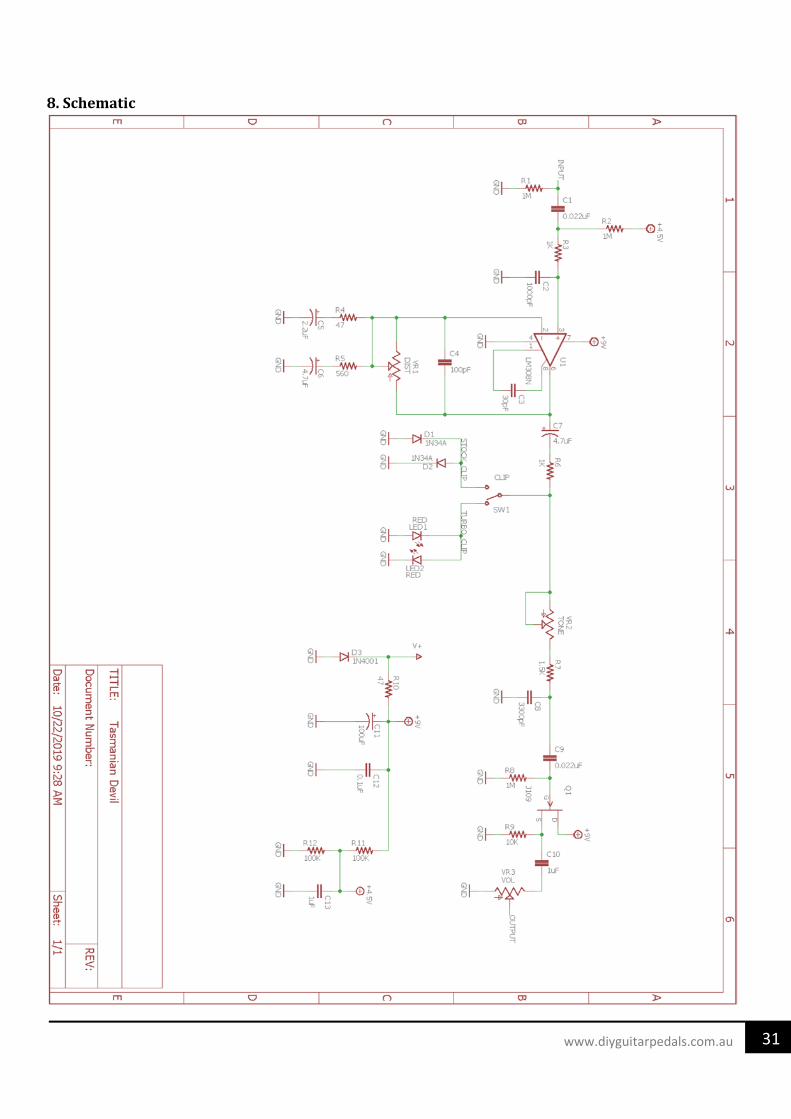
Tasmanian Devil Circuit Analysis for modifying purposes. 2. Tasmanian Devil Circuit. The Tasmanian Devil schematic can be broken down into some simpler blocks: Power Supply, Clipping Stage, Tone Level, and Output Stage.
The design is based on the LM308 single op-amp. The distortion is produced using a variable gain circuit with diodes clipping the waveform. The distortion stage is followed by a tone filter and an output buffer stage that ends up with a tone control.
The input impedance on the Tasmanian Devil is close to 157K Ω, allowing the pedal to not overload the pickups on the guitar or to tone suck, but as a rule of thumb, increasing to 1M would be ideal.

16www.diyguitarpedals.com.au
3. Power Supply. The Power Supply Stage provides the electrical power and bias voltage to all the circuitry, the whole power consumption is low and estimated around 5mA:
- The diode D3 protects the pedal against adapter reverse polarity connections.
- R10 along with C11 create a low pass filter of 33.9 Hz making sure no high frequency switching noise from a rogue power supply is able to bleed into the power rails. It also provides a small voltage drop of around 90mV.
- C11 is a large electrolytic capacitor used for bulk capacitance as well as a low pass filter for power.
- C12 is a small film capacitor used to filter higher frequency noise from the power supply.
- The resistors R11 and R12 form a voltage divider for the input and gain stages.
- C13 is a large film capacitor used as a decoupling capacitor for the 4.5V bias voltage.

17www.diyguitarpedals.com.au
4. Clipping Stage. The Clipping Stage is the core of the circuit which is made of a non-inverting op-amp amplifier with variable voltage gain, some filters to shape the distortion response, and hard clipping diodes.
- The R1 1MΩ resistor from the input to ground is an anti-pop/bleeder resistor, it will avoid abrupt pop sounds when the effect is engaged.
- The C1 22nF film capacitor is used as the input coupling capacitor, separating DC from the incoming op-amp, as well as forming a small RC filter with R2
- The R2 1MΩ resistor acts as an RC filter with C1, but primarily as a bias resistor for the U1 op amp. - The R3 1KΩ resistor acts as an RC filter with C2, as well as provides current limiting protections for the upcoming
op-amp. - The C2 1nF film capacitor is used as an RC filter with R3. - The C3 30pF small ceramic capacitor is a compensator capacitor for the op amp to help with slew rate - The C4 100pF small ceramic capacitor is used as an RC filter in the negative feedback loop of the op amp. - The R4 47Ω resistor is used as an RC filter along with C5 - The R5 560Ω resistor is used as an RC filter along with C6 - The C5 2.2μ electrolytic capacitor is used as an RC filter with R4 - The C6 4.7μ electrolytic capacitor is used as an RC filter with R5 - The distortion 100K potentiometer sets the variable gain of the op amp along with R4 and R5

18www.diyguitarpedals.com.au
- The C7 4.7μ electrolytic capacitor is a coupling capacitor that separates DC from the next part of the circuit as well as forms an RC filter with R6.
- The switch allows the Tasmanian Devil to switch between two different set of clipping diodes - The D1 and D2 diodes can be any kind of diode, such as standard silicon switching diodes (1N4148), rectifier
diodes (1N4001), Schottky diodes (1N5817), or Germanium diodes (1N34A) and are used for hard clipping the signal
- The LED1 and LED2 light emitting diodes can be any LED. Typically red LEDs are used, but other LEDs will have other forward voltage values, all of which perform an alternate form of hard clipping.

19www.diyguitarpedals.com.au
4.1 Input Impedance. The input impedance is defined by the formula: Zin = (R1 || R2) || (R3 + ZinLM308) According to the LM308 datasheet, the input resistance is typically 40M. If using an OP07C instead of an LM308N, input resistance is typically 33M
Zin = (1M || 1M) || (1K + 40M) Zin = 500,000 || 40,001,000 = 493,827Ω
Or if using an OP07
Zin = (1M || 1M) || (1K + 33M) Zin = 500,000 || 33,001,000 = 492,537Ω
However, due to the C2 capacitor adding resistance at higher frequencies (around 1 KHz), the input impedance falls to around 157 KHz
Lowering the capacitance of C2 improves the input impedance as the 1KHz mark. For example, if C2 drops to 470pF, at 1KHz, the input impedance raises to 284KΩ
150K-280KΩ as a high input impedance value and can be considered fairly-good for a distortion pedal. However, the best practice is to keep the input impedance at least in 1 MΩ, avoiding tone sucking. By increasing R1 and R2 values to 2.2MΩ for instance, will help raise the input impendence, especially on the lower frequencies.

20www.diyguitarpedals.com.au
4.2 Input Filtering. The 22nF cap C1 blocks DC and provides simple high pass filtering. All the interesting guitar signal will pass through, only harmonics below 7.2Hz will be attenuated. The cut-off frequency is defined by the formula: fc = 1 / (2π ⋅ R2 ⋅ C1) fc = 1 / (2π ⋅ 1M ⋅ 22nF) fc = 1 / (2π ⋅ 1,000,000 ⋅ 0.000000022) = 7.2Hz With a cut of 7.2Hz it will block DC and any low-frequency parasitic oscillation. The 1K resistor R3 protects the op-amp from input over currents. The 1nF cap C2 shunts high freqs to ground and out to mellow the signal. fc = 1 / (2π ⋅ R3 ⋅ C2) fc = 1 / (2π ⋅ 1,000 ⋅ 0.000000001) = 160 kHz With a cut of 160 KHz it will block out high frequency noise and any signal that might instigate oscillation, as the LM308 and OP07 can do from time to time if not careful.
4.3 Voltage Gain. The voltage gain is trimmed with the distortion knob, so in a non-inverting topology this can be calculated as:
Gv = 1 + (RDISTORTION / (R4 || R5)) Gvmin = 1 + (0 / (47 || 560)) = 1 (0dB) Gvmax = 1 + (100,000 / (47 || 560)) = 2305 (67dB) This voltage gain can be considered slightly high for a distortion pedal and similar to other distortion pedals. However, the voltage gain of this stage will not reach such values as 67dB. The gain will be limited by op-amp characteristics and also by the clipping diodes action, as it will be studied in the Diode Clipping Section.

21www.diyguitarpedals.com.au
4.4 Negative Feedback Low/High Pass Filtering. It is usual to find a combination of low pass and high pass filters before or within the clipping stage in distortion pedals. The distortion makes the original guitar signal more harmonically complex, this means that more amounts of distortion are being added, it can be more difficult to give each sound its own space in the band mix. Artificially band-limiting a distorted signal, using both high and low-pass filters, can help it sit more comfortably in a mix, by preventing its spectrum from spreading over too wide an area.
In the image above, the response of the Clipping Stage is shown. The signal is band limited in high and low frequencies. This mid hump around 1 kHz helps to keep the guitar sound from getting lost in the overall mix of the band.
Harmonics below 1.5 kHz and 60 Hz are attenuated due to the high-pass filters. In high frequencies there is also a roll-off because of the low pass filter and the op-amp gain-bandwidth product, both effects more noticeable at high-gain (blue lines).
Low Pass Filter.
The small 100pF capacitor C4 across the feedback resistor works as a low pass filter, softening the corners of the guitar waveform and mellowing out the high end before the clipping.
The cut-off frequency of the filter is defined by the formula:
fc = 1 / (2π ⋅ RDISTORTION ⋅ C4) fc = 1 / (2π ⋅ 100,000 ⋅ 0.0000000001) = 16 kHz
The Distortion potentiometer will shift the fc frequency, making the action of the 100pF is more dramatic when the distortion control is maxed out at 100K, bringing the cut-off minimum frequency to the audible frequencies (16 KHz) and then softening the distortion. When the distortion knob is not maxed out, the fc goes higher being less noticeable.
High Pass Filter.
There are two parallel RC networks formed by R4 C5 and R5 C6 from the (-) input to ground. They are an active high pass filter, placing two poles and attenuating frequencies below the cut-off frequencies:
fc = 1 / (2π ⋅ R4 ⋅ C5) fc = 1 / (2π ⋅ 47 ⋅ 0.0000022) = 1,540 Hz
fc = 1 / (2π ⋅ R5 ⋅ C6) fc = 1 / (2π ⋅ 560 ⋅ 0. 0000047) = 60.5 Hz
Harmonics below 1.5 kHz will have an attenuation 20dB/dec and lower harmonics below 60 Hz will be severely muted at 40dB/dec. This filtering provoke that bass notes will be attenuated before the clipping action, making the low end less clipped and creating a frequency selective distortion.

22www.diyguitarpedals.com.au
4.5 Op-Amp Selection. The original Pro Co Rat pedal uses the LM308N Motorola op-amp. After this op-amp went end-of-life, the Texas Instruments OP07DP was a replacement op-amp used in the new models. Part of the Rat's tone remains on the choice of the chip as a function of the Slew Rate, the Gain-Bandwidth Product, and the Compensation Capacitor:
The Slew Rate.
It refers to how fast the op-amp can swing its output. If the signal to be amplified is too fast (high frequencies), the op-amp will not be able to perform properly, only amplifying signals below the slew rate limit.
In the image above, the slew rate of the LM308 and OP07 is shown together with the TL071 (standard op-amp used in stomp boxes) for comparison purposes. The TL071 slew rate is 13V/μs while the LM308 and OP07 are 0.3V/μs. This means the LM308 and OP07 are 40 times slower, which in turn indicates how slow is the op-amp inside this pedal will be.
The slew rate is inversely proportional the compensator capacitor, the smaller the cap the faster the slew rate.
For a guitar signal (approximated to a sinusoidal wave) the Slew Rate of the op-amp will limit the rise speed of the signal following the equation:
SlewRate ≥ 2πf ⋅ Vpeak
Where Vpeak is 9V and the Slew Rate taken from the datasheet image is 0.3V/μs or 300000 V/s
fmax = SlewRate / (2π ⋅ Vpeak) = 300,000 / (2π ⋅ 9V) = 5.3 kHz
That means that the op-amp output will not be able of following harmonics higher than 5.3 kHz, so high frequencies will not pass through the amplifier, limiting or muting high harmonics.

23www.diyguitarpedals.com.au
The Gain-Bandwidth Product
It is relative to the gain setting; the Open Loop Frequency Response (gain-bandwidth product) graph below extracted from the datasheet, shows that not all frequencies can be amplified the same quantity.
For the Tasmanian Devil maximum voltage gain, which is 67dB, the frequencies below 500Hz will be amplified without problems, but higher frequencies will have less and less amplification as the graph shows. At 10 kHz, for instance, the max voltage gain will be no more than 30dB. Notice that this is where there are some slight differences between the LM308 and OP07. At 67dB, the frequencies below 800Hz will be amplified without problems and even at 10 kHz, the max voltage gain will be no more than 40dB.
In this way, the amplification of the guitar signal is frequency dependent, bass harmonics will take maximum gain while higher frequencies will suffer less gain.

24www.diyguitarpedals.com.au
The Compensation Capacitor.
Bandwidth and Slew Rate are proportional to 1/Ccompensation, the smaller the cap the bigger the Bandwidth and Slew Rate. The typical and suggested value by the datasheet is 30pF (same as used in the Tasmanian Devil’s design).
The above image shows again how the high frequencies are attenuated, using a 30pF cap for C3. Using bigger/smaller caps the Bandwidth and Slew Rate will be reduced/improved.
Summarizing these 3 effects, part of the signature sound of a Tasmanian Devil is essentially the op-amp collapsing under pressure and how the high-frequencies are attenuated and not treated in a linear way. The result of all this will be clipped by the diodes.
Overall Tone Response
Below is the tone response after leaving the op amp
Combined with the RC filters going into the op amp, ones in the negative feedback loop the overall tone response seems focused at around a 1.17 KHz hump across the full sweep of the distortion knob.

25www.diyguitarpedals.com.au
4.6 Diode Clipping. The silicon diodes D1 and D2 do hard-clipping on the pre-amplified signal creating symmetric distortion in a similar way as the MXR Distortion+ or Boss DS-1 do. When the voltage difference (positive or negative) between the op-amp output and ground is bigger than the diodes forward voltage VF, the diode will turn on. As the diode turns on forward biased, the signal will be clipped to the VF value. The diode D1 will clip the positive semi-cycle signal to +VF and D2 will clip the negative signal semi-cycle to -VF.
The Original Pro Co Rat uses 1N914 standard diodes, while the Turbo Rat used red LEDs in place of the standard signal switching diodes. With the Tasmanian Devil, we use both standard diodes and LEDs which can be switched between.
For the standard diodes, common switching diodes, like the 1N4148 can work in place of the 1N914. Space has also been left to use bigger diodes, such as 1N4001’s, Schottky Diodes such as 1N5817’s, or even Germanium Diodes, such as 1N34A’s.
For the LEDs, any T1 (3mm) LEDs will function, but note the forward voltages of the LEDs, as that will determine the clipping.
In the above graph, the input signal is represented in blue color. This original signal will be amplified by the op-amp until the power supply limits (line represented in purple). After the voltage gain, the diodes will clip the signal to ±VF.

26www.diyguitarpedals.com.au
5. Tone Level Stage. The Tasmanian Devil uses a passive Tone Control that is a simple low pass filter.
- The R7 1.5KΩ resistor sets the minimum resistance for the tone-potentiometer sweep. - The C18 3.3nF film capacitor is used as the capacitor in the RC filter formed with R7 and the tone pot. - The 100K tone potentiometer is used to vary the sweep of tone response after leaving the clipping diode section
5.1 Low Pass Filter. The cut-off frequency can be calculated as:
fc = 1 / (2π ⋅ (RTONE + R7) ⋅ C8) fcmin = 1 / (2π ⋅ (100,000 + 1,500) ⋅ 0.0000000033) = 475.4 Hz fcmax = 1 / (2π ⋅ (0 + 1,500) ⋅ 0.0000000033) = 32.2 kHz So the high harmonics above the frequency-cut selected by RTONE are attenuated like the graph below:
The range of the filter is pretty wide, being able to sweep almost all the audio spectrum from 475 Hz to 32 kHz. The Tone Control combined with all the other filters placed in the pedal will create a mid-hump, to be analyzed in the Frequency Response Section.

27www.diyguitarpedals.com.au
The clipped waveform will be affected by the low pass filter, as shown above, creating a shark fin shape as the tone control is dimed.
The overall tone response over the tone-sweep, including what was filtered from the early stages would look like this:

28www.diyguitarpedals.com.au
6. Output Buffer. The Output Stage is a JFET unity gain amplifier in common drain (source follower) configuration. It is placed to create a low output impedance which is good to keeping tone integrity in the signal chain. It also isolates the volume stage from the Tone Control in order to make both controls independent, otherwise changing the volume will alter the tone:
- The C9 22nF film capacitor is used as a coupling capacitor, separating DC from the incoming JFET, as well as forming a small RC filter with R8.
- The R8 1MΩ resistor biases the JFET gate to ground. - The R9 10KΩ resistor acts as a source resistor for the JFET buffer. Any value between 3.3K and 10K will work
here with little difference in sound. - The C10 1μF film capacitor is used as an output coupling capacitor. - The 100K volume knob is used to bleed signal to ground to decrease its signal volume.
6.1 Output Impedance. The input impedance is defined by the formula: Zin = (R9 || VR3) || (ZoutQ1) JFETs output impedance varies, but when measuring a couple J109s, I found the average to be around 485 ohms. So to calculate output impedance:
Zin = (10K || 100K) || (485) Zin = 9,091 || 485 = 460Ω
As an ideal output impedance should be under 10K, 460 ohms is a terrific output impedance.

29www.diyguitarpedals.com.au
7. Voltage Readouts. Below are the voltage readouts of the ICs onboard, assuming 9V Power Supply.
IC and FET read-outs
KNOBS
- VOL: MAX - TONE: MAX - DIST: MAX - NORMAL SWITCH

30www.diyguitarpedals.com.au
8. Modifications Following is a couple of worthwhile modifications that can be applied to the Tasmanian Devil. 8.1 Capacitors Increasing C4 to 220pF will reject higher frequency harmonics from the original 16 kHz down to 7 kHz, smoothing out the tone of the distortion some. Decreasing to 47pF will allow more high frequency harmonics to come into the distortion. In the feedback of the op-amp, changing values of C5 and C6 (along with R4 and R5, respectively) can affect the hump of frequencies that are gained. Lowering the capacitance increases the frequency cut point while increasing the capacitance lowers the frequency cut points. In the tone section, increasing C8’s capacitance will allow for more bass frequencies while decreasing C8’s capacitance will reject more bass frequencies. 8.2 Resistors In the feedback of the op-amp, changing values of R4 and R5 (along with C5 and C6, respectively) can affect the hump of frequencies that are gained. Lowering the resistance increases the frequency cut point while increasing the resistance lowers the frequency cut points. In the tone section, increasing R7’s resistance will allow for more bass frequencies while decreasing R7’s resistance will reject more bass frequencies. However, due to the setup, you’ll have a more drastic effect by modifying the C8 capacitance. 8.3 Diodes D1 and D2 can be any type of diode and not necessarily match, creating an asymmetrical clipping effect. The same is true with the LEDs for the clipping switch. LEDs of different forward voltages will create an asymmetrical clipping effect. 8.4 Op-Amps Changing the op amp will have some effect to the sound of your signal, especially if you go away from op amps with poor slew rates to ones with good ones. For example, where an LM308 or OP07 is too slow to react to frequencies above 5.3 kHz, a TL071 can react properly to frequencies close to 23 kHz, well over the human ear’s capacity to note. Also, the open-loop frequency at higher gain will also make it up into the 10’s of kHz, unlike the LM308 and OP07, which cap out at under 1 kHz. If using these types of single op-amps, you will not need to populate, and probably shouldn’t populate, C3.
31www.diyguitarpedals.com.au
8. Schematic

5/21/2021 3:45 PM f=0.61 C:\Users\evincent\Desktop\Tasmanian Devil\1590B Enclosure.brd
INOUT
STOMP
LED
POWER
VOL TONE DIST
TURBO NORMAL

5/21/2021 3:58 PM f=0.61 C:\Users\evincent\Desktop\Tasmanian Devil\Tasmanian Devil 125B.brd
STOMPLED
POWER
INOUT
VOL TONE DIST
NORMALTURBO
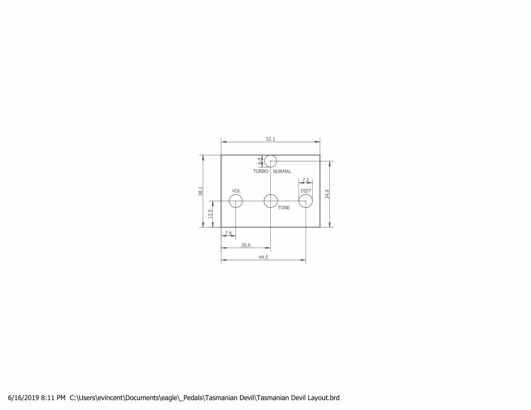
6/16/2019 8:11 PM C:\Users\evincent\Documents\eagle\_Pedals\Tasmanian Devil\Tasmanian Devil Layout.brd
VOL
TONE
DIST
38.1
52.1
13.9
7.6
26.0
44.5
7.2
34.9
6.4
NORMALTURBO