the station of nick m0rao my interests are broad in...
TRANSCRIPT

The Station Of Nick M0RAO
My interests are broad in respect of radio and I am happy to be a member ofthe WARC with there being so many knowledgeable members, to help me
to take my interests to new horizons and in turn pass on what I have learnt to others.
I am also thankful for the friendships I have made in such a short period of time.
As I said my interests are broad, I like to be aware of all aspects of communication,whilst specializing at present on the 2 metre band where my station is capable ofMoon Bouncing, Meteor Scatter and Tropo etc modes.
JOURNAL JANUARY 2007 ISSUE 58
WARRINGTON AMATEUR RADIO CLUB
www.warc.org.uk

2
The station transceivers for 2m operation are as followsFT 847, Kenwood TR751e multimode, Yaesu FT 221R all mode, Yaesu FT 1000MP mark 5 with Down East Microwave Transverter and recently an Elecraft K2with an Elecraft Transverter.
The PA section is a Mirage driver amp,which I would like to replace with avalve one at some point, into a homebrew PA7 TA design RF deck as builtby G0 RUZ.The specification is as follows:-GS35B valve (Russian triode) withG3SEK board. The power supply is 4kilovolts and with full input drive iscapable of 2500w output, so at Tropooperation at 400w at the aerial, thisamplifier is barely ticking over.As you are all aware 2500w key downis a reasonable amount of output pow-er, even with line losses taken intoaccount and you can very easily be inexcess of legal limit if not careful. Soto rectify this I use a Bird peak reading
Cont’d on page 4

3
ContentsPage Title Author Call Sign
1 The Station Of Nick M0RAO Nick M0RAO
6 and 7 Centre Page Pullout Solar Activity Paul NA5N
8 Broadband QRM Jim G3NFB
9 Just Two Of His Disasters Albert G3ZHE
10 The Club Calls Contest 2006 Albert G3ZHE
10 The Latest News of the CDG2000 Georg G3OGQ
12 W A R C Committee 2007 Ron G0WJX
Anyone wishing to contribute to the magazine should send or give their copy to theeditor Ron, G0WJX preferably in MS Word, .txt format or e-mail.
Club ProgrammeDate Title SpeakerJan 16 Club Annual General MeetingJan 23 Club Annual DinnerJan 30 Peter Island 3Y0X Mike G4VSSFebruary RSGB 80m Club Championships5th SSB, 14th Data, 22rd CW
Feb 06 Sunspots (Speaker needed) Recent Sunspot Activity effects on HFFeb 13 Preparation for NorbreckFeb 20 Switch Mode Power Supplies (speaker Needed)Feb 27 Club Championship Discussion Forum. Your idea to improve our score
Offers or ideas for talks to the programme coordinator Albert G3ZHE
Club ContactsSecretary Paul Carter G7ODJChairman Cliff Robinson M0MRC Tel. [email protected] fees to Treasurer Bill Rabbitt G0PZP [email protected]

4
meter on output to measure the true peaks and compress my output signal to keepan accurate reading.Transmission lines are LDF 550, LDF450,Ecoflex15 and Belden going to a water-proof box which houses two preamps onebeing an lNA technology cavity and theother being a smaller lNA to compensatefor the Mutek band pass filter insertionloss. There is also a SSB electronics coaxrelay and a series of resistors for heat tokeep damp out of the box.My aerials are mounted on a Strumech P60tower (Versatower) and also a P40 mobilemast with a Cushcraft R7000 vertical aeri-al. The tower has a medium model Pro SisTel worm driven rotator, then 20 foot alu-minium scaffold pole, which gives me 80foot from ground to my 17 element M2aerial.At present I am experimenting with oneaerial with no elevation and the factthat I am using no elevation can give me asmuch as 6 db of ground gain for EME.The next phase is to take the equipment to
a farm location and build 8 DJ9BV aerials on my mobile tower away from noiselevels of the town. Also in such a remote location I can apply for a licence for a highpower EME station for experimental purposes.Just to clarify I run two transmission lines, one for receive and one for transmission.This completes my 2m station.HF Station2 Kenwood / Trio 930s, FT 901de, FT 847 and Icom 706 Mk 2,P A is a Drake L4B (3500z pair output) 1kw key down for 80w drive.Again this amp ticks over at 400w peak and virtually no line loss as it is fed withLDF 450 to a KLM KT34A 4 element tribander on top of my P60 tower giving me10m 15m and 20m.For 40m to 160m I use various wire dipoles and experiment with helium balloons.I am also thinking of shunt feeding my tower - again for 80m.
From page 4
5
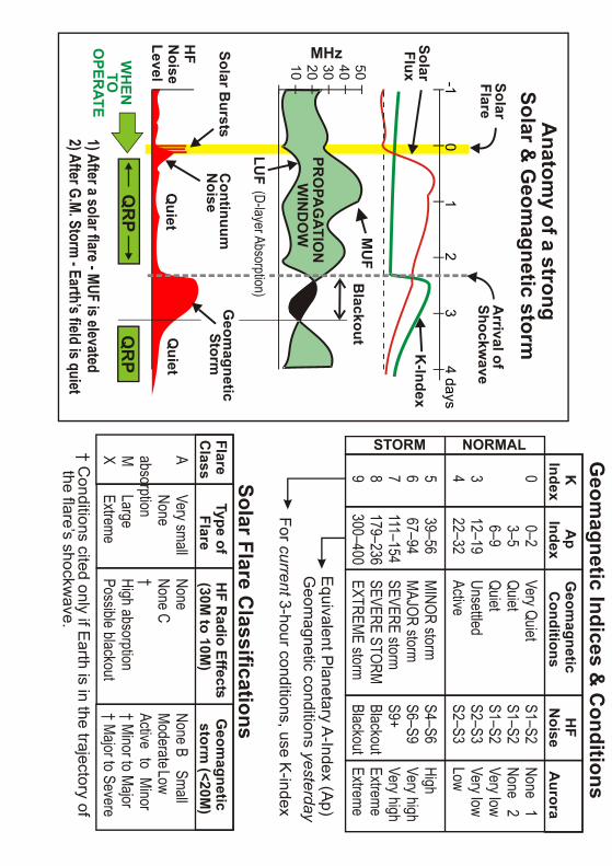
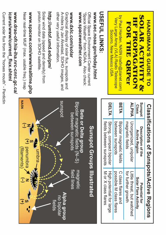
Solar Activity & HF PropagationCentre Page Pull-out Members who attended the QRP rally at Rochdale were able to attend a lecture byPaul Harden NA5N who came all the way from New Mexico. His handout containsmuch useful information and links for anyone with an interest in solar activity andH F propagation and it was suggested to me that it should be reproduced in QSX.Paul not only agreed that we could feature it but also sent me the original full colourversion. Thanks Paul and we look forward to seeing you again at Rochdale.
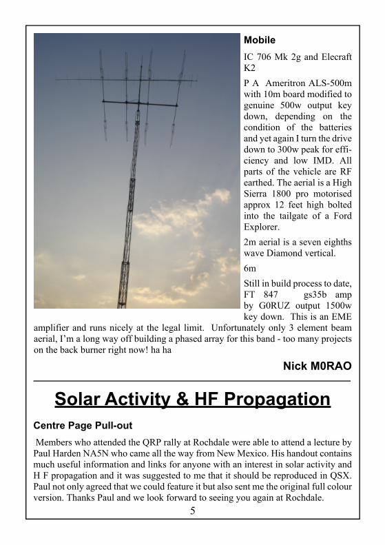
MobileIC 706 Mk 2g and ElecraftK2P A Ameritron ALS-500mwith 10m board modified togenuine 500w output keydown, depending on thecondition of the batteriesand yet again I turn the drivedown to 300w peak for effi-ciency and low IMD. Allparts of the vehicle are RFearthed. The aerial is a HighSierra 1800 pro motorisedapprox 12 feet high boltedinto the tailgate of a FordExplorer.2m aerial is a seven eighthswave Diamond vertical.6mStill in build process to date,FT 847 gs35b ampby G0RUZ output 1500wkey down. This is an EME
amplifier and runs nicely at the legal limit. Unfortunately only 3 element beamaerial, I’m a long way off building a phased array for this band - too many projectson the back burner right now! ha ha
Nick M0RAO
0 0–2
Very Quiet S1–S2
None 1
3–5 Quiet
S1–S2 None 2
6–9
Quiet S1–S2
Very low3
12–19 Unsettled
S2–S3 Very low
4 22–32
Active S2–S3
Low
5 39–56
MINOR storm S4–S6
High6
67–94 MAJOR storm
S6–S9 Very high
7 111–154
SEVERE storm S9+
Very high8
179–236 SEVERE STORM
Blackout Extreme
9 300–400
EXTREME storm Blackout
Extreme
A Very small
None None B
Small
None None C
Moderate Lowabsorption
† Active to Minor
M Large
High absorption † Minor to Major
X Extreme
Possible blackout † Major to Severe
K A
p Geom
agnetic HF
Index Index Conditions N
oise Aurora
Flare Type of HF R
adio Effects Geom
agneticC
lass Flare (30M to 10M
) storm (<20M
)
STORM NOR AM L Geom
agnetic Indices & C
onditions
Solar Flare Classifications
† Conditions cited only if E
arth is in the trajectory ofthe flare’s shockw
ave.
Equivalent P
lanetary A-Index (A
p)G
eomagnetic conditions
yesterdayForcurrent 3-hour conditions, use K
-index
-1 0 1 2 3 4 days
5040302010
MHz
MU
F
LUF
PRO
PAG
ATION
WIN
DO
W
Blackout
K-Index
SolarFlux
Solar Bursts
Continuum
Noise
Geom
agneticStorm
SolarFlare
Arrival of
Shockwave
Anatom
y of a strongSolar &
Geom
agnetic storm
HF
Noise
LevelQ
uiet Q
uiet
QR
P Q
RP
WH
ENTO
OPER
ATE1) After a solar flare - MUF is elevated2) After G.M. Storm
- Earth’s field is quiet
(D-layer Absorption)
HA
ND
IMA
N’S
GU
IDE
TO
SO
LA
R A
CTIV
ITY &
HF P
RO
PA
GATIO
NFO
R T
HE
QR
Per
by Paul H
arden, NA
5N (na5n@
zianet.com)
Very Large Array (V
LA) R
adio TelescopeS
ocorro, New
Mexico U
SA
USEFU
L LINK
S:w
ww
.sec.noaa.gov/today.html
ww
w.spacew
eather.com
ww
w.dxlc.com
/solar
Official Space E
nvironment C
enter current“Space W
eather” from N
OA
A. A
lso check:
Graphical display of solar flux, sunspots and
A-index by Jan A
lvestad, SO
HO
images, and
other very useful information.
Solar w
ind data (speed and density) fromproton m
onitor on SO
HO
satellite.
Near real-tim
e MU
F (max. usable freq.) m
ap
http://umtof.um
d.edu/pm/
ww
w.spacew
.com/w
ww
/realtime.php
ww
w.drao-ofr.hia-iha.nrc-cnrc.gc.ca/
icarus/ww
w/current_flux.shtm
lC
urrent solar flux from the “horses m
outh” - Pentictin A
LPHA
U
norganized, unipolar Little threat, but w
atchedm
agnetic fields for further grow
thB
ETA
Bipolar m
agnetic fields C
class flares andbetw
een sunspots possible M
class flaresD
ELTA
Strong, compact bipolar
High potential for large
fields between sunspots
M or X
class flares
SunspotC
lassD
escription of theA
ctive Region
Potential forSolar Flare A
ctivity
Classifications of Sunspots/A
ctive Regions
Sunspot Groups IllustratedA
lpha groupno bipolar
fields
magnetic
field lines
sunspot
umbra
penumbra
(filaments)
Beta or D
elta groupB
ipolar magnetic fields (N
–S)
between sunspots
N(–) (+)
(+)(–)
SS
NN
A5N

8
Broadband QRM
Over the Christmas holidays I took part in the G-QRP Club Winter Sportsactivity, with very little success. Apart from the poor conditions I had a
particularly annoying problem with QRM for a couple of days until I cured it.
The QRM was in the form of spikes spaced every 30 kHz, pulsing every 2 seconds,across the whole HF spectrum. On 14 MHz and 18MHz they were S9 and theywere coming through the antenna.At first I thought that they were being generated in my computer but on switchingit off I found they were still there.Then I suspected that they were coming from my switch mode power supply so Iswitched it off and found that the QRM was receivable on a portable Rx so it wasnot that.After having switched off everything in sight the QRM was still there so to try toestablish whether or not it was in my locality, I phoned Albert G3ZHE across town.He told me that he was not getting similar QRM so I had confirmed that it was localto me.The next thing to do was to try to track down the QRM by DF-ing with my portableHF receiver and a loop antenna. Before I got around to doing this I tried to accessthe internet to pick up my e-mail which I had not read for a couple of days. It wasthen that I discovered that I could not connect. Eventually I found that the problemwas at my computer where the connection from the NTL broadband box hadloosened despite the plug being still inserted into the computer.I pushed the connector fully home. I was then able to pick up my e-mail, but bestof all my QRM problem disappeared and has not returned since then. I suspect thatI had had an open screen between the cable connector and the computer socket.
Jim G3NFB
Winston Churchill QuoteHistory will be kind to me, for I intend to write it.
Jim G3NFB
9
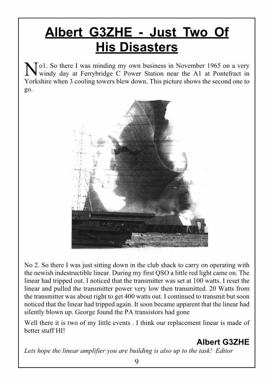
Albert G3ZHE - Just Two OfHis Disasters
No1. So there I was minding my own business in November 1965 on a verywindy day at Ferrybridge C Power Station near the A1 at Pontefract in
Yorkshire when 3 cooling towers blew down. This picture shows the second one togo.
No 2. So there I was just sitting down in the club shack to carry on operating withthe newish indestructible linear. During my first QSO a little red light came on. Thelinear had tripped out. I noticed that the transmitter was set at 100 watts. I reset thelinear and pulled the transmitter power very low then transmitted. 20 Watts fromthe transmitter was about right to get 400 watts out. I continued to transmit but soonnoticed that the linear had tripped again. It soon became apparent that the linear hadsilently blown up. George found the PA transistors had goneWell there it is two of my little events . I think our replacement linear is made ofbetter stuff HI!
Albert G3ZHELets hope the linear amplifier you are building is also up to the task! Editor

10
The Club Calls Contest 2006
It’s November 11th again so it must be The RSGB Clubs Calls Contest. Novem-ber 11th was a bad weather day with high winds and lots of rain. This year the
club could not find a suitable site so I said I would set the Club Station up in mygarage. It also forced me to do a big clean up in the garage. Keith G8MKO said hewas pleased to be in the garage and not putting antennas up in a wet field.Keith G8MKO, Ian M0BXR, Paul G1DVA, Dave G0RVW and me G3ZHEbecame the team.The station was an Icom 756 pro3 and an MFJ ATU. The antenna was a 150ft endfed in the form of an inverted U with 25ft up, 90ft horizontal at 30ft high, and 25 ftdown at the far end. We also used two 132ft radials running along the ground.The band had the usual S9 noise levels. G0WRS/P was our call and we worked 44stations - 22 club stations and 22 club members.The points are 3 points for each QSO that’s 3 times 44=132. We also get a bonusof 5 points for each radio club member worked so 22 times 5=110. We get a bonusof 25 points for every Club Station worked. 22 times 25=550. So the totalis132+110+550=792 points.I checked my score at this QTH and with the same set up for the 2005 contest I got740 points. I am not sure what the club got from Mike's QTH (M0ACK) in St Helens.We worked every station we could hear and met a few call signs from the 80mcontest.We had beer and snacks available but we must report a heroine, Ian’s wife Jennie.Ian arrived with a tin of mince pies. Needless to say he took the tin home empty!They tasted great - “MORE PLEASE".You may have to wait for the Christmas 2007 countdown Albert! Editor
Albert G3ZHE
The Latest News of the CDG2000
A week or two ago I entered the Club Home Construction Contest with the latestversion of the CDG2000 and had the opportunity to describe how it was
designed and built.
It was suggested to me that members might be interested in hearing what effect thedesign had, and is still having, on the Amateur Radio world.
11
When the design was originally published, in 2002, it created no little interest in thecognoscenti who understood what the performance figures meant. What they meantwas a breakthrough in receiver design which signified a great leap forward.Nearlyfive years later the design is still unsurpassed although Colin is still working at itand has produced some improvements in certain of the figures which will lead tothe possibility of producing a general coverage receiver with the same performanceas a dedicated Ham Bands only front end. Both Icom and Yaesu have produced newtransceivers which give superior performance figures to their earlier designs andone has to look at the advertised figures very carefully before deciding that the HolyGrail, nearly achieved by the CDG, is still a long way off. For example, look at thewidely advertised figures for IP3 of +40dBm for the Icom version. You have tolook very closely at the reviews to see that this is in a bandwidth of 100kHz asopposed to 2kHz for the CDG. Similarly note the absence of local oscillator phasenoise figures in their adverts and look at the reviews compared with the CDG.Several critics have inferred that our measurements are flawed and too optimistic.These criticisms have been shot down by measurements taken by a number ofindependent amateurs (and professionals) who agree with our figures. The ARRL(not known for giving non-US amateurs any credit) included most of the design –including a photograph of the CDG made by me – in their book “ExperimentalMethods in RF Design”.The design has been taken up by hundreds of builders, many of whom have usedcommercial PCBs designed by the team and sold by them but the number ofbuilders who have made their own far exceeds these. Our boards have beenexported to 33 countries including (dare we say it) Japan. The UK has not provedto be a home constructor nation and even Poland has more constructors than wehave. China asked us for the Gerber files so that they could produce their ownboards and we gave them the necessary information. We know that at least 21copies have been built in China. One of the problems with developing countries isthe cost of building the CDG. For example, one of the required chips (the DDSchip) is unfortunately no longer made in 28 pin dip but supplies are available fromAllied Electronics in USA at $25 plus postage etc. Chinese amateurs tell us that thisis more that a weekly wage for an RF engineer! In one or two cases we have giventhem the chip but we cannot do it for every case.Talking about the cost, a British amateur went to the trouble of costing every itemand came to the conclusion that the cost of the parts was £808.91 excludinghardware, cabling, IC sockets, low pass filters and PA – probably under £1000altogether. This did not encourage British builders who see home construction as away to save money.It is interesting that the most frequently asked question by British amateurs is “Howmuch does it cost” compared with all other countries who ask “where do I get theparts from”- probably the reason why British constructors are heavily outnumbered
W A R C Committee 2007
As a result of the Annual General Meeting on 16th January the officers andcommittee are as follows:-
Chairman Clifford Robinson M0MRCVice Chairman Paul Middlehurst G1DVATreasurer William Rabbitt G0PZPSecretary Paul Carter G7ODJEvents Coordinator Albert Heyes G3ZHEWeb Master Ian White M0BXRMagazine Editorial Team and Publicity Ronald Davies G0WJX Christopher Davies G7GZBLibrarian Anthony Jones G0YSSEquipment Manager George Fare G3OGQGYCA Representative Guy Wood G8NRFNARSA Representative Brian Helsdon G6XRERaffle Organiser Keith Pocock G8MKOAuditor Guy Wood G8NRF
by almost every other country. This is, I believe, partly due to the attitude of theRSGB who relegate home construction articles to the back of RadCom and whoofficially often say that only a few amateurs build their own, thus putting us in theposition of cranks. I am concerned that this attitude will eventually lead to “typeapproval” of Ham Radio equipment which for me would be the death knell of thehobby.However let’s look to the future. Dave Roberts is at present designing a completeDSP section which will not only give the usual receiver gimmicks like filtering,noise reduction etc but will also generate SSB signals and shape them. I hope tohave a prototype going by the NARSA Rally. Constructors have told us that theonly thing wrong with the CDG is that it does not have DSP – Waters and Stantontell us that it is nearly impossible to sell a rig without it, regardless of the benefitsor otherwise. After all, the better the transceiver, the less effect DSP will have.Anyway, watch this space, as they say.
George G3OGQ