the spe foundation through member donations … spe foundation through member donations and a...
TRANSCRIPT
Primary funding is provided by
The SPE Foundation through member donations
and a contribution from Offshore Europe
The Society is grateful to those companies that allow their
professionals to serve as lecturers
Additional support provided by AIME
Society of Petroleum Engineers
Distinguished Lecturer Programwww.spe.org/dl 1
Recent Advances in Horizontal Well Water Shut-Off and Production Improvement
Keng Seng ChanPetronas
Society of Petroleum Engineers
Distinguished Lecturer Programwww.spe.org/dl
2
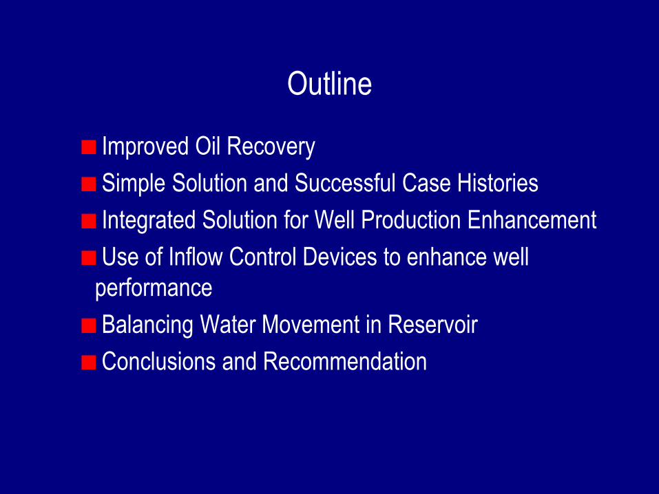
Outline
Improved Oil Recovery
Simple Solution and Successful Case Histories
Integrated Solution for Well Production Enhancement
Use of Inflow Control Devices to enhance well
performance
Balancing Water Movement in Reservoir
Conclusions and Recommendation
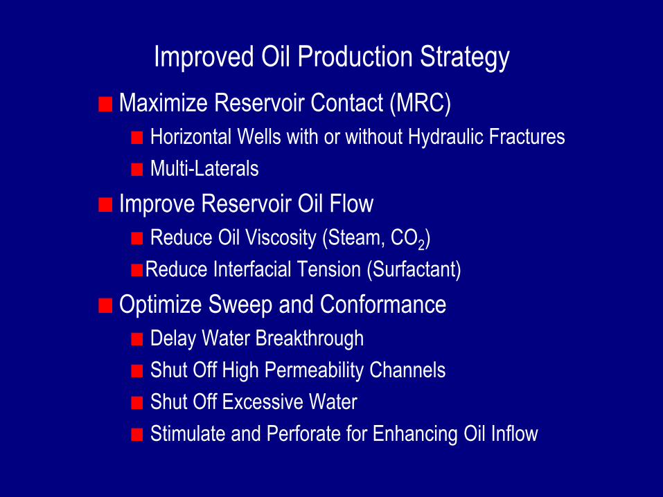
Improved Oil Production Strategy
Maximize Reservoir Contact (MRC)
Horizontal Wells with or without Hydraulic Fractures
Multi-Laterals
Improve Reservoir Oil Flow
Reduce Oil Viscosity (Steam, CO2)
Reduce Interfacial Tension (Surfactant)
Optimize Sweep and Conformance
Delay Water Breakthrough
Shut Off High Permeability Channels
Shut Off Excessive Water
Stimulate and Perforate for Enhancing Oil Inflow
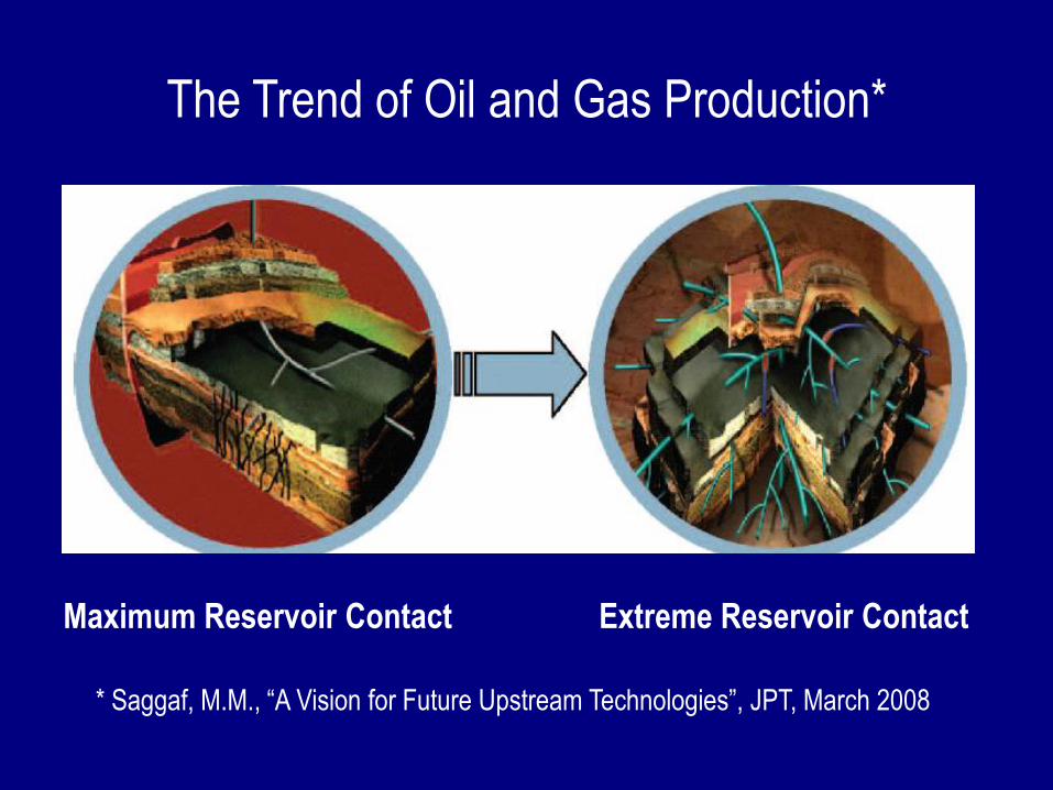
Maximum Reservoir Contact Extreme Reservoir Contact
The Trend of Oil and Gas Production*
* Saggaf, M.M., “A Vision for Future Upstream Technologies”, JPT, March 2008
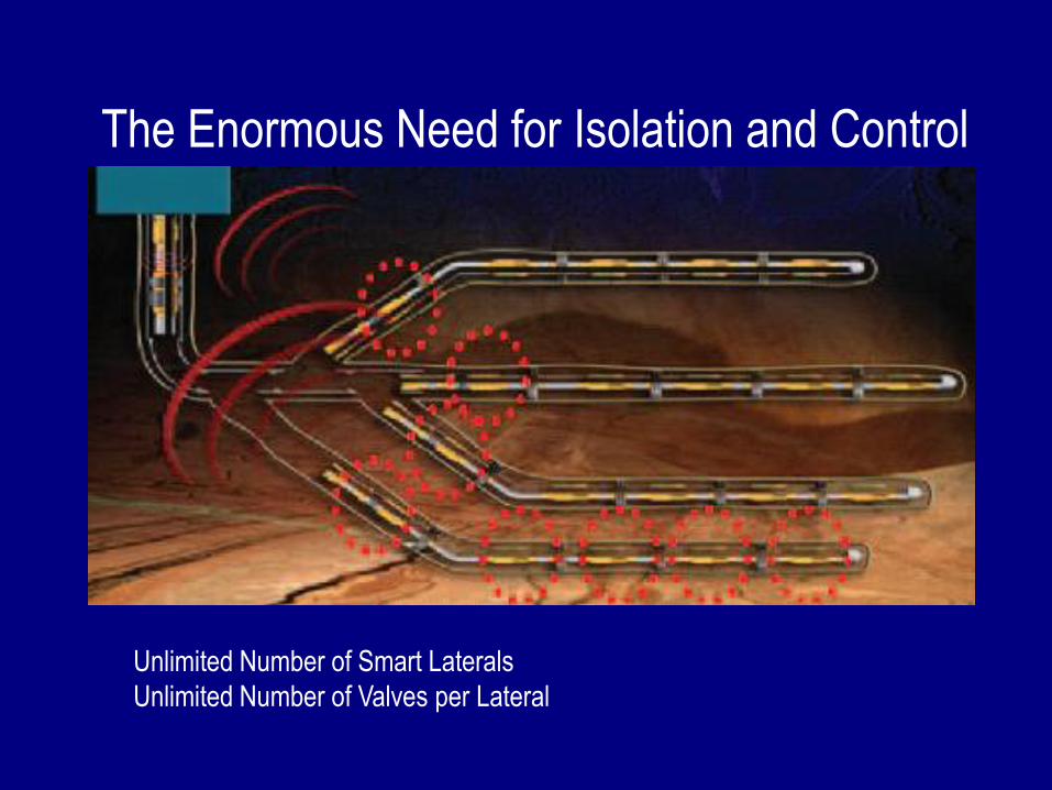
Unlimited Number of Smart Laterals
Unlimited Number of Valves per Lateral
The Enormous Need for Isolation and Control
West Wing
East Wing
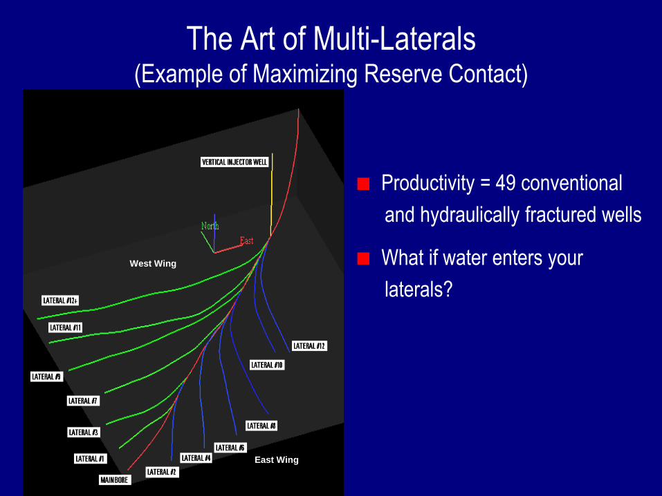
The Art of Multi-Laterals (Example of Maximizing Reserve Contact)
Productivity = 49 conventional
and hydraulically fractured wells
What if water enters your
laterals?
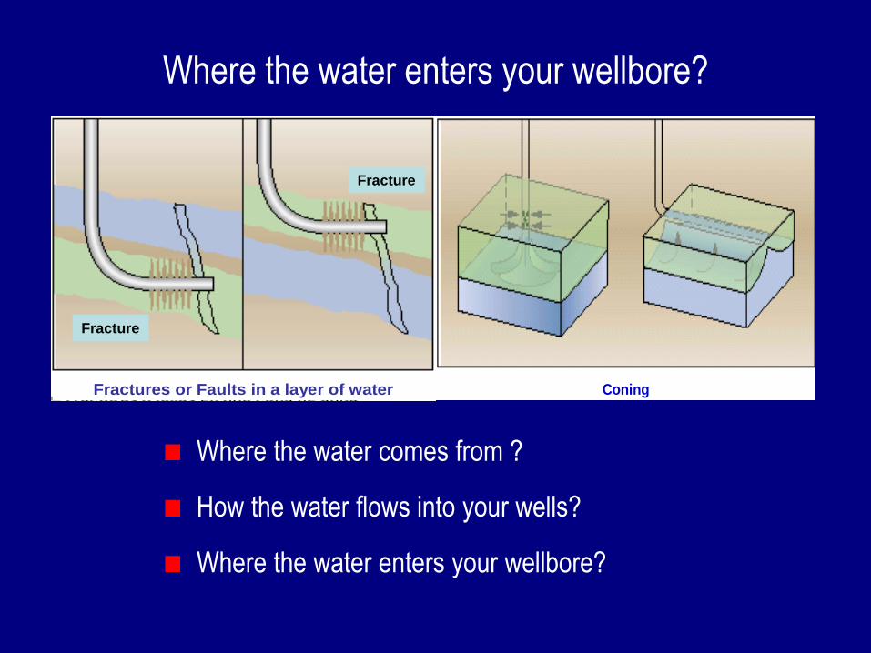
Fractures or Faults in a layer of water (horizontal well)
Coning
Where the water enters your wellbore?
Where the water comes from ?
How the water flows into your wells?
Where the water enters your wellbore?
Fracture
Fracture
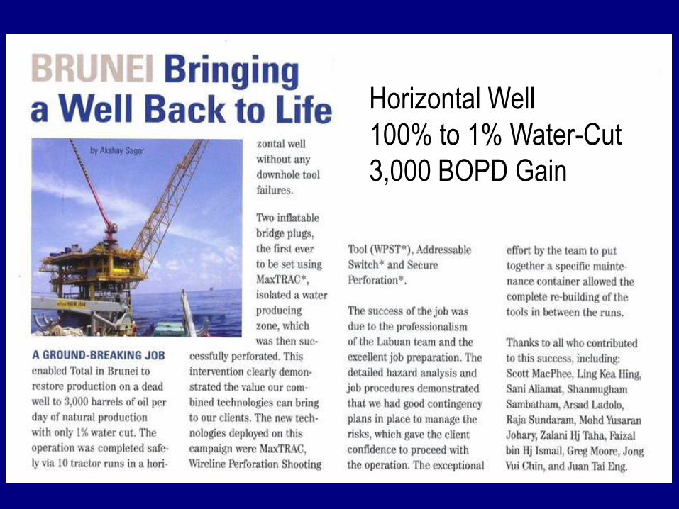
Horizontal Well
100% to 1% Water-Cut
3,000 BOPD Gain
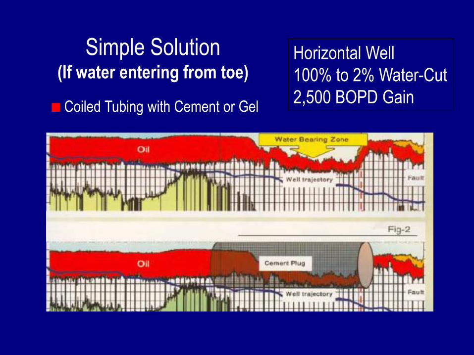
Horizontal Well
100% to 2% Water-Cut
2,500 BOPD Gain
Simple Solution(If water entering from toe)
Coiled Tubing with Cement or Gel
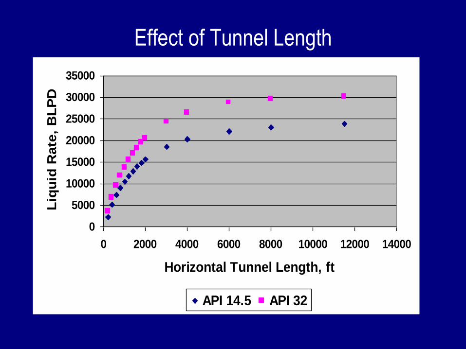
Effect of Tunnel Length
0
5000
10000
15000
20000
25000
30000
35000
0 2000 4000 6000 8000 10000 12000 14000
Horizontal Tunnel Length, ft
Liq
uid
Rate
, B
LP
D
API 14.5 API 32
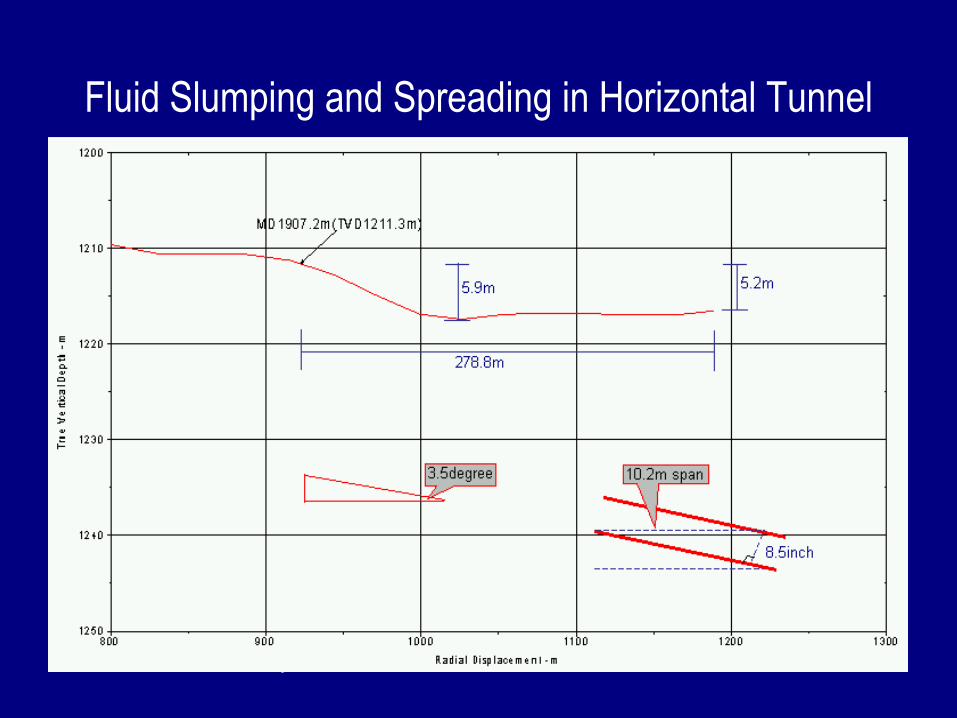
Fluid Slumping and Spreading in Horizontal Tunnel
> 60o
Thixotropic Fluids
-Highest injection point is 1907.2m MD
-Slumping span is about 9.6m
-Highest injection point is 1907.2m MD
-Slumping span is about 9.6m
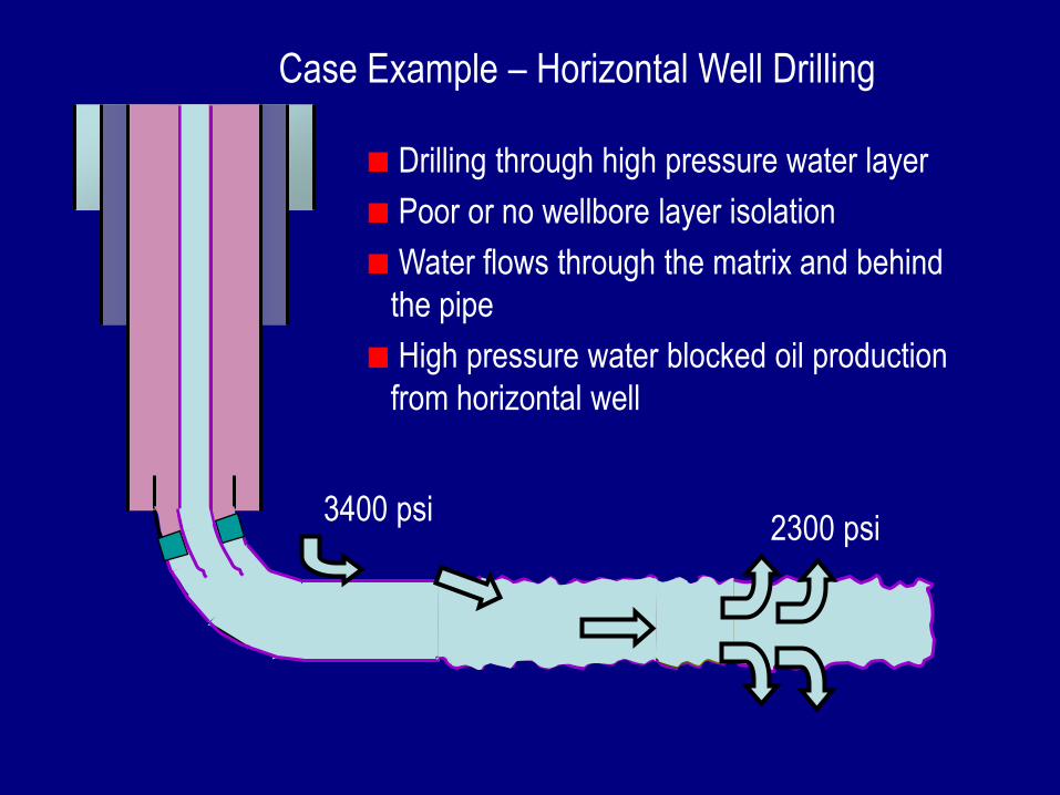
3400 psi2300 psi
Drilling through high pressure water layer
Poor or no wellbore layer isolation
Water flows through the matrix and behind
the pipe
High pressure water blocked oil production
from horizontal well
Case Example – Horizontal Well Drilling
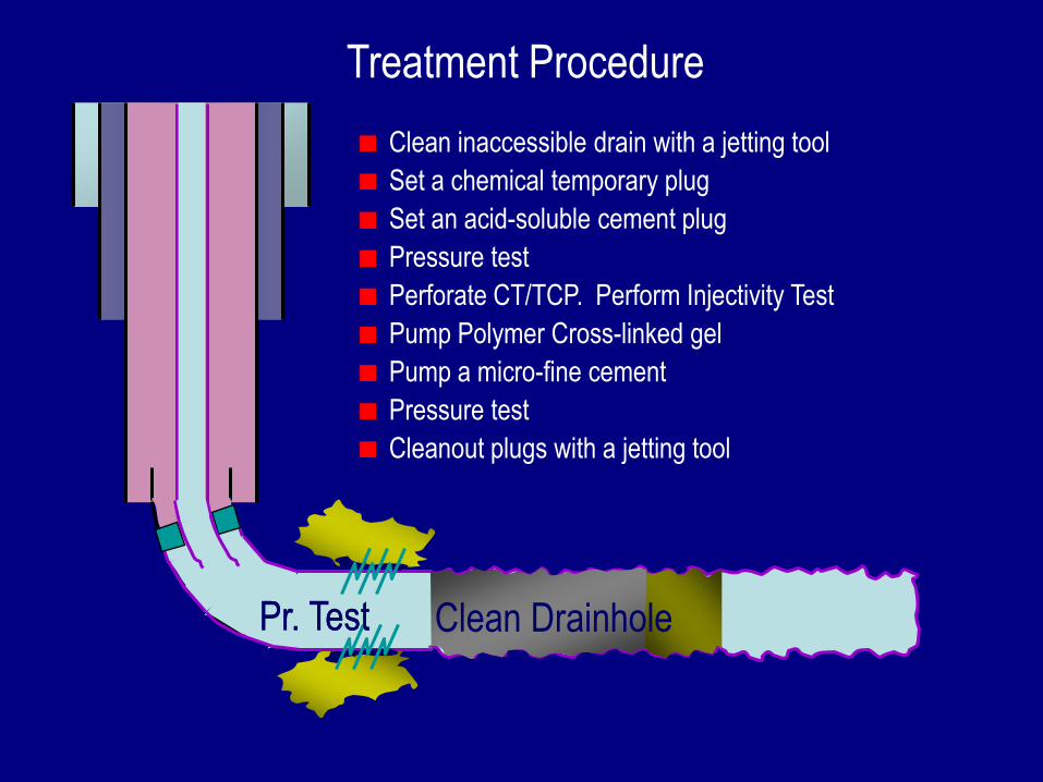
Clean inaccessible drain with a jetting tool
Set a chemical temporary plug
Set an acid-soluble cement plug
Pressure test
Perforate CT/TCP. Perform Injectivity Test
Pump Polymer Cross-linked gel
Pump a micro-fine cement
Pressure test
Cleanout plugs with a jetting tool
Clean DrainholePr. TestPr. Test
Treatment Procedure
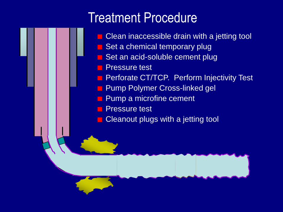
Treatment ProcedureClean inaccessible drain with a jetting tool
Set a chemical temporary plug
Set an acid-soluble cement plug
Pressure test
Perforate CT/TCP. Perform Injectivity Test
Pump Polymer Cross-linked gel
Pump a microfine cement
Pressure test
Cleanout plugs with a jetting tool
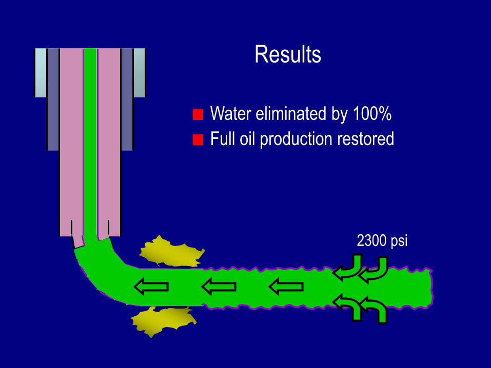
2300 psi
Results
Water eliminated by 100%
Full oil production restored
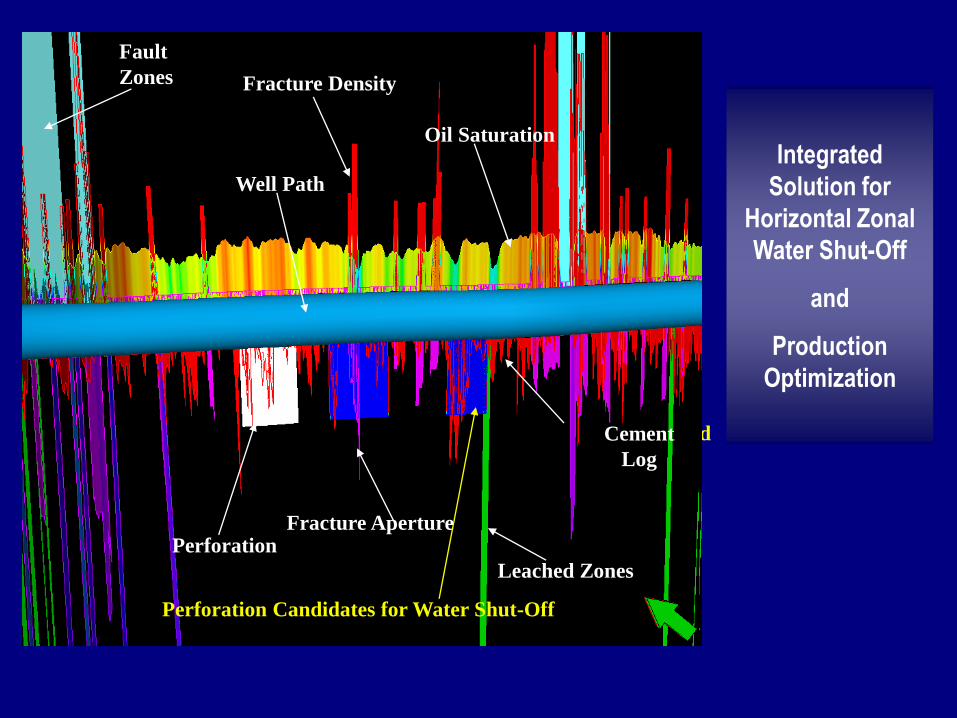
Well Path
Fracture Density
Fracture Aperture
Fault
Zones
Leached Zones
Well Path
Fracture Density
Fracture Aperture
Fault
Zones
Leached Zones
RST oil Sat.
Well Path
Fracture Density
Fracture Aperture
Fault
Zones
Leached Zones
RST oil Sat.
Cement Bound
Log
Well Path
Fracture Density
Fracture Aperture
Fault
Zones
Leached Zones
RST oil Sat.
Cement
Log
Perforation
Well Path
Fracture Density
Fracture Aperture
Fault
Zones
Leached Zones
Oil Saturation
Cement
Log
Perforation
Perforation Candidates for Water Shut-Off
Integrated
Solution for
Horizontal Zonal
Water Shut-Off
and
Production
Optimization
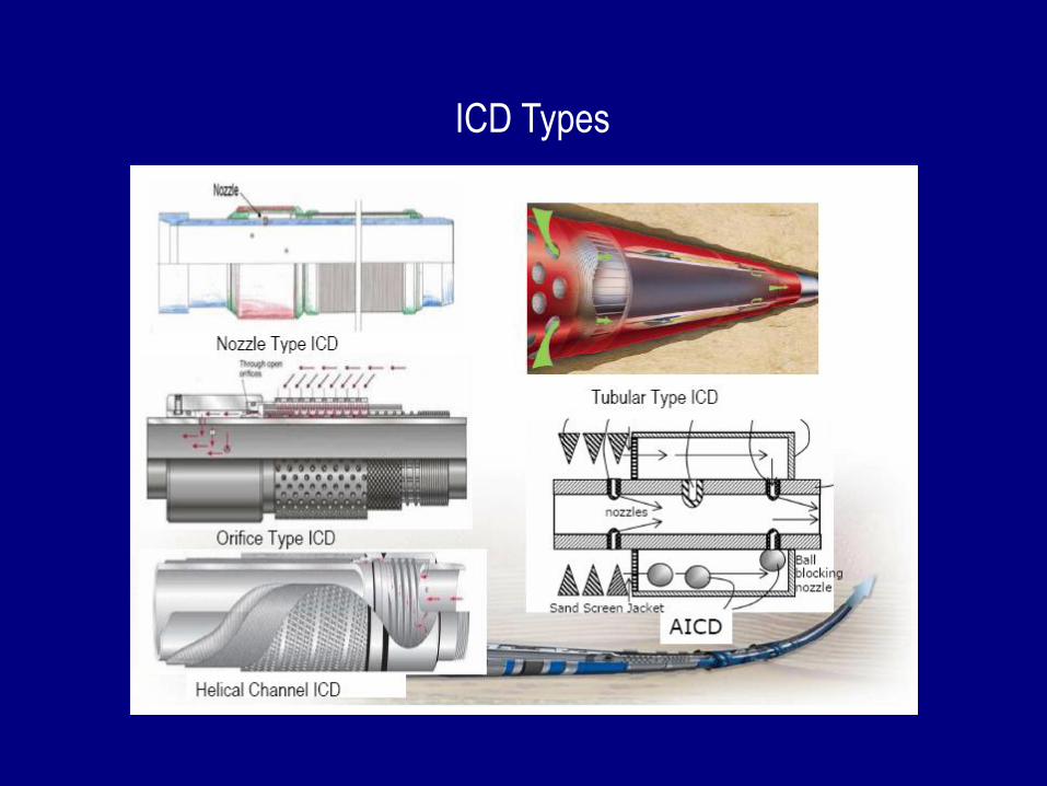
ICD Types
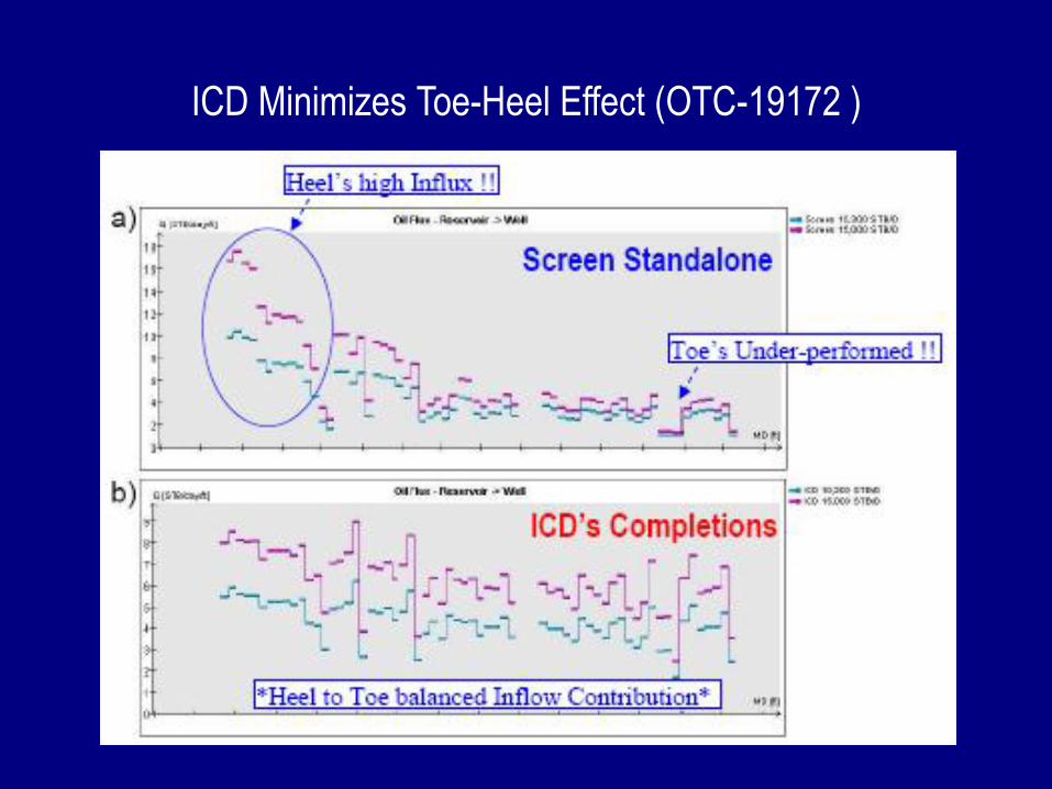
ICD Minimizes Toe-Heel Effect (OTC-19172 )
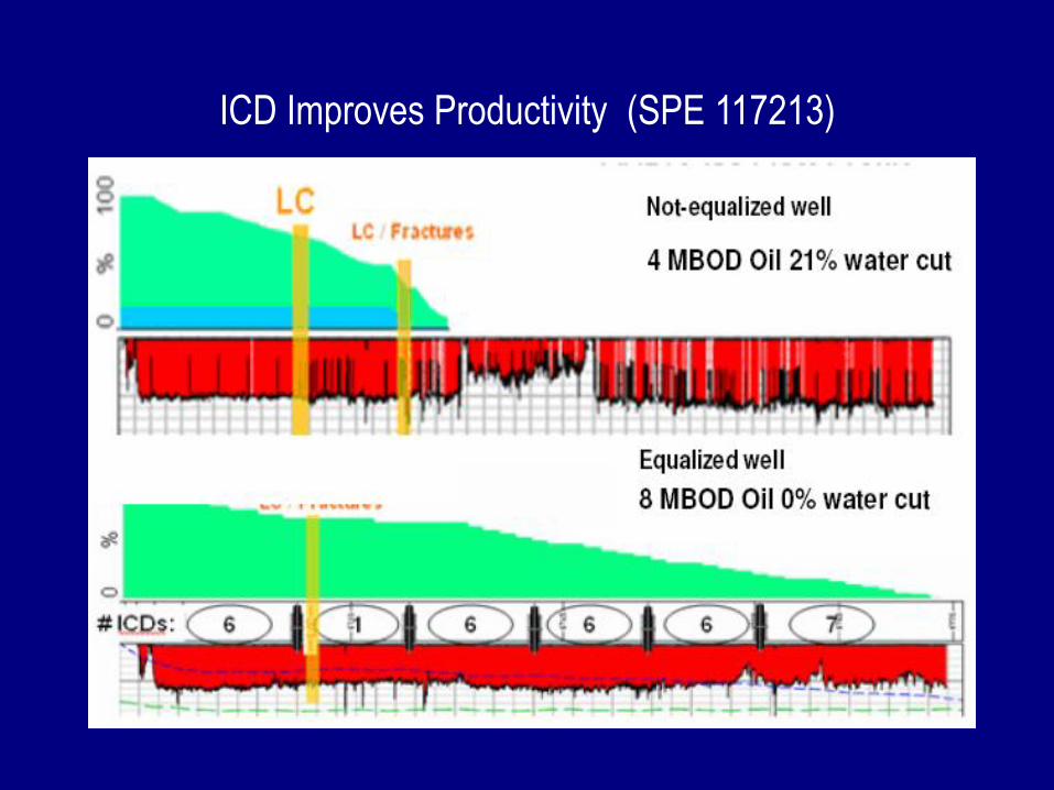
ICD Improves Productivity (SPE 117213)
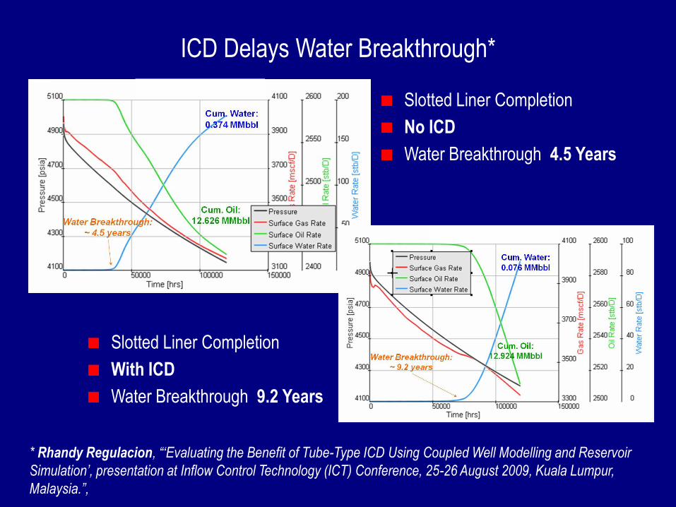
ICD Delays Water Breakthrough*
Slotted Liner Completion
No ICD
Water Breakthrough 4.5 Years
Slotted Liner Completion
With ICD
Water Breakthrough 9.2 Years
* Rhandy Regulacion, “„Evaluating the Benefit of Tube-Type ICD Using Coupled Well Modelling and Reservoir
Simulation‟, presentation at Inflow Control Technology (ICT) Conference, 25-26 August 2009, Kuala Lumpur,
Malaysia.”,
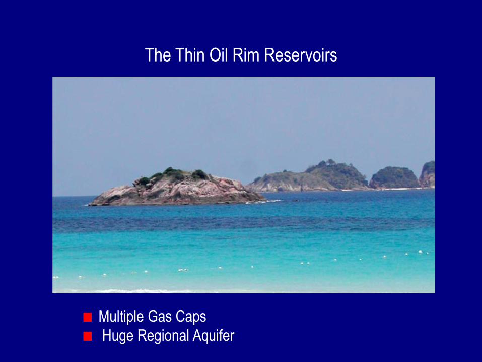
The Thin Oil Rim Reservoirs
Multiple Gas Caps
Huge Regional Aquifer
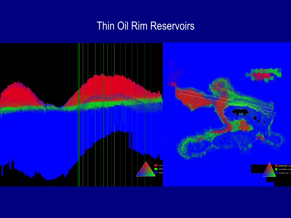
Thin Oil Rim Reservoirs
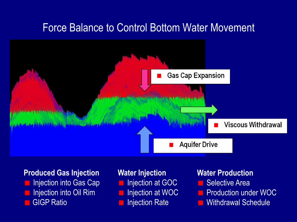
Force Balance to Control Bottom Water Movement
Produced Gas Injection
Injection into Gas Cap
Injection into Oil Rim
GIGP Ratio
Water Injection
Injection at GOC
Injection at WOC
Injection Rate
Water Production
Selective Area
Production under WOC
Withdrawal Schedule
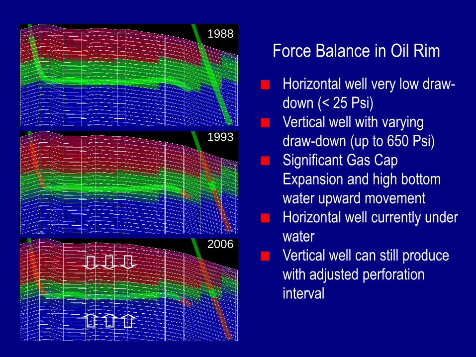
Force Balance in Oil RimWest
1988
1993
2006
Horizontal well very low draw-
down (< 25 Psi)
Vertical well with varying
draw-down (up to 650 Psi)
Significant Gas Cap
Expansion and high bottom
water upward movement
Horizontal well currently under
water
Vertical well can still produce
with adjusted perforation
interval
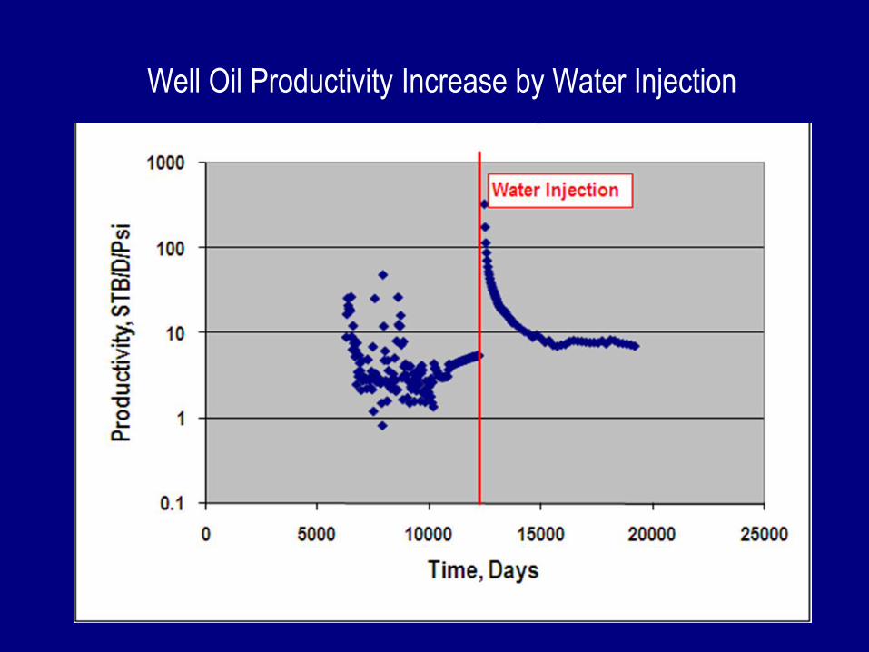
Well Oil Productivity Increase by Water Injection
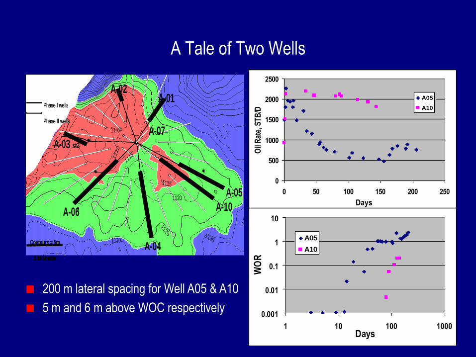
A Tale of Two Wells
A-06
A-04
A-10
A-05
A-01A-02
A-03 st3
Contours = 5m
1 kilometer
1120
1115
1125
1130
11151
110
1105
1135
Phase I wells
Phase II wells
A-07
A-06
A-04
A-10
A-05
A-01A-02
A-03 st3
Contours = 5m
1 kilometer
Contours = 5m
1 kilometer
1120
1115
1125
1130
11151
110
1105
1135
Phase I wells
Phase II wells
Phase I wells
Phase II wells
A-07
0.001
0.01
0.1
1
10
1 10 100 1000Days
WO
R
A05
A10
0
500
1000
1500
2000
2500
0 50 100 150 200 250
Days
Oil
Rat
e, S
TB
/D
A05
A10
200 m lateral spacing for Well A05 & A10
5 m and 6 m above WOC respectively
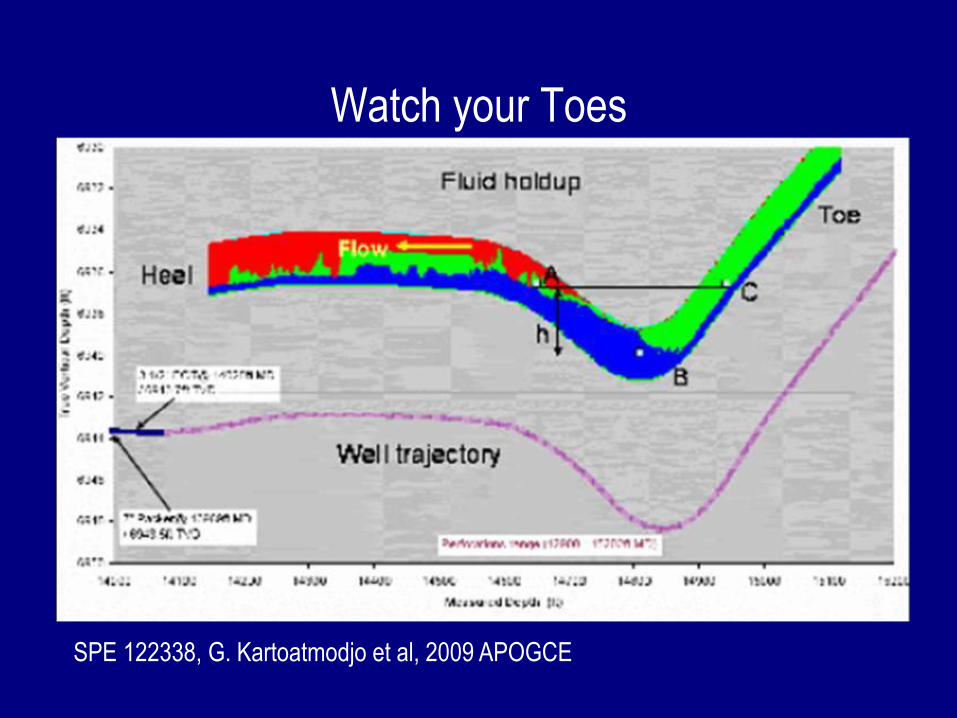
Watch your Toes
SPE 122338, G. Kartoatmodjo et al, 2009 APOGCE
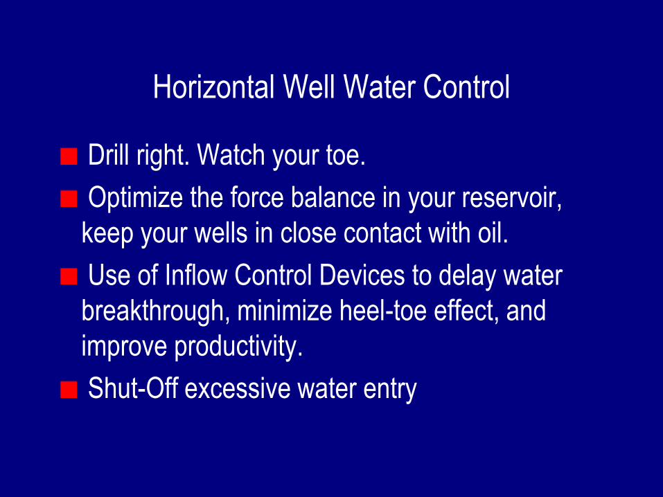
Horizontal Well Water Control
Drill right. Watch your toe.
Optimize the force balance in your reservoir,
keep your wells in close contact with oil.
Use of Inflow Control Devices to delay water
breakthrough, minimize heel-toe effect, and
improve productivity.
Shut-Off excessive water entry
Society of Petroleum Engineers
Distinguished Lecturer Programwww.spe.org/dl 31
Your Feedback is Important
Enter your section in the DL Evaluation Contest by
completing the evaluation form for this presentation or
go online at:
http://www.spe.org/events/dl/dl_evaluation_contest.php