the science and application of nanosilver chip- …...the science and application of nanosilver...
TRANSCRIPT

G-Q. Lu presentation at 2014 APEC Annual Meeting (3/2014) 1
2014 APEC Annual Meeting Fort Worth, TX March 19th, 2014
The Science and Application of Nanosilver Chip-bonding Material
Guo-Quan (GQ) Lu, Professor
Dept. of MSE and ECE, Virginia Tech, USA

G-Q. Lu presentation at 2014 APEC Annual Meeting (3/2014) 2
Outline
I. Conventional LTJT by silver sintering versus nanosilver-enabled LTJT
II. Sintering behavior of nanosilver paste
III. Drying behavior of large-area nanosilver bond-line
IV. Application of nanosilver for making double-side cooled power modules
V. Summary

G-Q. Lu presentation at 2014 APEC Annual Meeting (3/2014) 3
High-temperature packaging research at Virginia Tech’s Center for Power Electronics Systems (CPES)
3. Die-attach material (Nanoscale Ag paste)
Power Device
2. Encapsulant
4. Substrate
1. Planar device assembly
Conventional Power Modules
One-side cooling; Solder: fatigue; low-melting temp;
and low thermal conductivity
Th(Homologus Temperature) = Toperating/Tmelting
Source: Knoerr, Kraft, and Schletz, Fraunhofer Institute for ISDT
G-Q. Lu presentation at 2014 APEC Annual Meeting (3/2014) 4
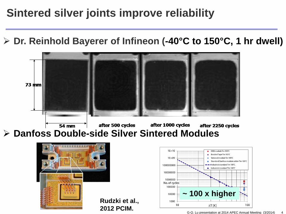
Sintered silver joints improve reliability
Danfoss Double-side Silver Sintered Modules
~ 100 x higher Rudzki et al., 2012 PCIM.
Dr. Reinhold Bayerer of Infineon (-40°C to 150°C, 1 hr dwell)

G-Q. Lu presentation at 2014 APEC Annual Meeting (3/2014) 5
Conventional LTJT – a complex manufacturing process
Temperature: 240oC – 250oC
Time: 2 – 5 minutes
Pressure: 20 – 40 MPa or 200 – 400 kg force per cm2.
Long process development time
From: C. Gobl and J. Faltenbacher, CIPS’2010

G-Q. Lu presentation at 2014 APEC Annual Meeting (3/2014) 6
Mackenzie-Shuttleworth Sintering Model (1960s):
Theoretical basis (trading chemical for mechanical force):
Mobility
ηρρ
αργρ /1*)1
1ln*)11(*1(*)1(*)(*23 3/1
−−−−+= appliedP
rdtd
Driving Force
30 nm Ag Powder 100 nm Ag Powder
The science of replacing mechanical force by thermodynamic driving force

G-Q. Lu presentation at 2014 APEC Annual Meeting (3/2014) 7
Outline
I. Conventional LTJT by silver sintering versus nanosilver-enabled LTJT
II. Sintering behavior of nanosilver paste
III. Drying behavior of large-area nanosilver bond-line
IV. Application of nanosilver for making double-side cooled power modules
V. Summary

G-Q. Lu presentation at 2014 APEC Annual Meeting (3/2014) 8
Surfactant Ag nano- powder
Organic thinner
Uniform Dispersion Nanosilver paste nanoTach®
+ + Binder Thinner
Surfactant
Formulation of nanosilver paste
Use of organics to prevent:
a) nano-particles from agglomeration and cracking;
b) surface diffusion at low temperature so that rapid densification can take place at high temperature.

G-Q. Lu presentation at 2014 APEC Annual Meeting (3/2014) 9
Removal of organics is necessary for sintering
Exothermic peak from polymer combustion
1 2 4 3
1
2
3 4

G-Q. Lu presentation at 2014 APEC Annual Meeting (3/2014) 10
-5 0 5 10 15 20 25 30 35 4080
84
88
92
96
100
27.9min298.1oC 31.1min
321.0oC18.7min207.3oC
22.6min245.6oC
12.4min144.7oC
12.1min141.6oC
Time/min
Tem
pera
ture
/o C
Wei
ght/%
NSP-10-Air NSP-10-N2
0
50
100
150
200
250
300
350
400
AirNitrogen
Paste: N-080528-IIB
10oC/min
Oxygen is necessary for sintering

G-Q. Lu presentation at 2014 APEC Annual Meeting (3/2014) 11
~ 50% shrinkage of bond-line thickness due to drying and sintering
0 20 40 60 80 100 120-12
-10
-8
-6
-4
-2
0
2
4
Chan
ge o
f Thi
ckne
ss /u
m
Time/min
75
80
85
90
95
100
W
eigh
t /%
Paste: N-080528-IIB
Weight loss curve
Thickness shrinkage curve

G-Q. Lu presentation at 2014 APEC Annual Meeting (3/2014) 12
Outline
I. Conventional LTJT by silver sintering versus nanosilver-enabled LTJT
II. Sintering behavior of nanosilver paste;
III. Drying behavior of large-area nanosilver bond-line;
IV. Application of nanosilver for making double-side cooled power modules
V. Summary

G-Q. Lu presentation at 2014 APEC Annual Meeting (3/2014) 13
Glass “chip” nanoAg paste
Understanding the kinetics of paste drying for pressure-less bonding of large IGBT chips
Bonding large chips
25oC 39oC 53o
C 75o
C 100oC 113oC 122oC 127oC 140oC 154oC 167oC 180oC 186oC 186oC 186oC 184oC 180oC
1 cm
1 cm
Cracks Gaps or debonding
and

G-Q. Lu presentation at 2014 APEC Annual Meeting (3/2014) 14
xσ
yσzσ
Unit cell of paste
Solvent evaporation and diffusion due to thermodynamics
and kinetics
Intention to shrink due to
surface tension
Shrinkage constrained due to
bonding at substrate and chip
h chip
paste
Unit cell failure due to high
internal stress
A diffusion-viscous analysis of bond-line drying
1. Solvent evaporation at the chip edges (liquid to gas transition);
2. Solvent molecular diffusion within the bond-line;
3. Shrinkage of the bond-line; 4. Stress development within the bond-
line cracks and delamination
Kinetic processes:

G-Q. Lu presentation at 2014 APEC Annual Meeting (3/2014) 15
0
50
100
150
200
0 10 20 30 40 50 60
Tem
pera
ture
(°C
)
Time (min) 0 min
0 min
4 min
4 min 10 min
10 min
14 min
14 min 16 min
16 min
20 min
20 min
22 min 25 min
22 min 25 min
35 min
35 min
45 min
45 min
55 min
55 min
σx cracking
Modeling result of stresses in the bond-line
1 cm
Nano-Ag paste
Glass chip
1 cm
0 min 4 min 10 min 14 min 16 min 20 min 22 min 25 min 35 min 45 min 55 min
σz debonding
Drying

G-Q. Lu presentation at 2014 APEC Annual Meeting (3/2014) 16
How to eliminate bond-line defects?
Substrate
Chip Silver paste
Max internal stress causing debonding: 2.7 MPa Max internal stress causing cracking: 11.0 MPa
Zero pressure bonding cracks & debonding
Die-shear strength <10 MPa
3 MPa Press
substrate
Silver paste
Max internal stress causing debonding: 1.3 MPa Max internal stress causing cracking: 2.8 MPa
chip
A. Mechanical Route B. Chemical Route
Substrate
Chip
Addition of easy-flow component into the paste to allow silver particles
slide over one another reducing internal stresses
Pressure-free bonding Drying at 3 MPa
Die-shear strength >25 MPa Die-shear strength > 25 MPa
2 mm
10 mm x 10 mm chip Void content < 2%

G-Q. Lu presentation at 2014 APEC Annual Meeting (3/2014) 17
Comparison to soldering large-area chips
X-ray Imaging
Acoustic Imaging
Void content > 15%
SST Vacuum Reflow Soldering system
PINK Formic Acid Soldering system
> $150 K
Void < 1%

G-Q. Lu presentation at 2014 APEC Annual Meeting (3/2014) 18
Outline
I. Conventional LTJT by silver sintering versus nanosilver-enabled LTJT
II. Sintering behavior of nanosilver paste
III. Drying behavior of large-area nanosilver bond-line
IV. Application of nanosilver for making double-side cooled power modules
V. Summary

G-Q. Lu presentation at 2014 APEC Annual Meeting (3/2014) 19
Motivation
Source: NREL
105oC coolant
Engine
Radiator cooling
Cooled to 65oC
Power Electronics
Extra cooling loop required for power electronics
High-temp power electronics capable of Tj ~ 200oC would eliminate the extra cooling loop lower cost.

G-Q. Lu presentation at 2014 APEC Annual Meeting (3/2014) 20
Nanosilver enabled double-side cooled, planar power modules (Version I: half-bridge) Three-phase Inverter
Current state-of-the-art IGBT Module
Planar, double-side cooled module

G-Q. Lu presentation at 2014 APEC Annual Meeting (3/2014) 21
54mm
4mm thin
25.4mm
Bottom DBC- Positive Bus
Top DBC- Negative Bus
Gate/Emitter output
Version II of nanosilver sintered planar power modules (quarter-bridge)
Two Q-bridge modules connected to form a half-bridge module

G-Q. Lu presentation at 2014 APEC Annual Meeting (3/2014) 22
Three-phase testing of half- and quarter-bridge nanosilver sintered planar power modules
Vcc
APS Gate Driver Board
Phase A
Phase B
Phase C
A+
A-
B+
B-
Input Signal
C+
C-
A+ A- B+ B- C+ C-DC Link Sense
Bus Bar Current
Output Current (Phase A)
DC-Link Voltage
Vge of High-Side IGBT (Phase A)
3-phase testing results at 750V 75 Amps

G-Q. Lu presentation at 2014 APEC Annual Meeting (3/2014) 23
Pressure-free heating in pure nitrogen or forming gas (4%H2-N2)
Most recent developments – bonding to copper in controlled atmosphere

G-Q. Lu presentation at 2014 APEC Annual Meeting (3/2014) 24
High die-shear strength and reliable sintered silver-to-copper joints
Temperature cycling Power cycling
(∆T = 135oC) (Temp range from -40oC to 125oC)

G-Q. Lu presentation at 2014 APEC Annual Meeting (3/2014) 25
Most recent developments – nanosilver preform
Step II: Pressure-sintering
Step I: Preform transfer to chip or substrate

G-Q. Lu presentation at 2014 APEC Annual Meeting (3/2014) 26
Summary
The LTJT by silver sintering is emerging as a competitive lead-free, die-attach solution for manufacturing power devices/modules because sintered silver joints are significantly more reliable.
By studying the drying and sintering properties of a nanosilver paste, the paste formulations have been optimized for pressure-free bonding of large-area (13 mm x 13 mm) IGBT chips.
Using nanosilver paste can significantly lower the cost of implementing LTJT because it requires simpler tooling and offers higher throughput and yield.

G-Q. Lu presentation at 2014 APEC Annual Meeting (3/2014) 27
Questions or Comments?
Thank you for your attention!
Acknowledgements: • US Office of Naval Research
• US Army Research Laboratory
• US Department of Energy
• NBE Technologies, LLC
• US National Science Foundation & Chinese NSF
• Prof. K. Ngo, Dr. G. Lei, Dr. J.N. Calata, Dr. J. Mei, Dr. K. Xiao, H. Zheng, Dr. T. Wang, Li Jiang, D. Berry, Y. Yao, X. Cao, Prof. X. Chen, Dr. J. Bai, Dr. Z. Zhang, and Dr. S. Luo

G-Q. Lu presentation at 2014 APEC Annual Meeting (3/2014) 28