the role of smart wireless communications in advancing ... · ©2005 microchip technology...
TRANSCRIPT

© 2005 Microchip Technology Incorporated. All Rights Reserved. Slide 1
The Role of Smart Wireless Communications in Advancing
Automotive Security Applications
Youbok Lee, Ph.D.James B. Nolan
Microchip Technology Inc.2355 West Chandler Blvd.
Chandler, AZ 85224 USA

© 2005 Microchip Technology Incorporated. All Rights Reserved. Class Slide 2
1. What is Smart Wireless Communications?2. Application Examples3. Programmable Digital Wake-Up Filter4. Amplitude Sensitivity and Modulation Depth5. Examples: Smart Passive Keyless Entry (PKE)
System Design6. Conclusions7. References
Table of Contents

© 2005 Microchip Technology Incorporated. All Rights Reserved. Class Slide 3
Example: Keyless Entry Systems(Yesterday and Today)
Encrypted Codes
UHF Receiver
Microcontroller(MCU)
LED
MCU(KEELOQ®)
UHF Transmitter
LED

© 2005 Microchip Technology Incorporated. All Rights Reserved. Class Slide 4
1. What is Smart Wireless
Communications ?
● Hands-Free Operation (no human interface) ● 100% Reliable and Stand-Alone● Self-Learning and Self-Adaptable

© 2005 Microchip Technology Incorporated. All Rights Reserved. Class Slide 5
Small Size and Low Cost
Inexpensive Bi-directional Communication
A smart microcontroller (MCU) that has both digital and analog -front-end circuits in a single package.
Use 125 kHz for the base station command, and UHF for the response.
Requirements Solutions
High input sensitivity of the transponder for the base-station command: ~ 3 mVpp
CommunicationDistance: > 2 meters
Requirements and Solutions

© 2005 Microchip Technology Incorporated. All Rights Reserved. Class Slide 6
Minimum Antenna Directionality
Long Battery Life
Use three orthogonally placed LF antennas on the transponder board.
Use wake-up filter
Requirements Solutions
Work for Noisy Environment
High input modulation depth sensitivity
Requirements and Solutions(Continued)
Data Security Use encryption/decryption algorithms

© 2005 Microchip Technology Incorporated. All Rights Reserved. Class Slide 7
Example:Smart Passive Keyless Entry (PKE) Systems
(Tomorrow)
Command
(125 KHz)
Response
(UHF)
Response
(125 KHz)
Encrypted Codes
UHF Receiver
LFTransmitter/
Receiver
Mic
roco
ntro
ller
(MC
U)
LED
Smart MCU
UHF Transmitter
LED
X
Y
Z

© 2005 Microchip Technology Incorporated. All Rights Reserved. Class Slide 8
Circuit Elements to Receive Signals Coming From All Directions
Smart MCU
X
Y
Z
Bx
Bz
By

© 2005 Microchip Technology Incorporated. All Rights Reserved. Class Slide 9
UHF TXUHF TX(315/434 MHz)(315/434 MHz)
Example: PKE Transponder Configuration
VDD
DataRFEN
LFDATA/SDIO
VDDT
LCX
LCY
VSS
LED
VSST
LCCOM
LCZ
CS
SCLK/ALERT
3 V
3 V
3 V
3 V1
2
3
4
5
6
7
8
9
10
20
19
18
17
16
15
14
13
12
11
PIC
16F6
3 9

© 2005 Microchip Technology Incorporated. All Rights Reserved. Class Slide 10
2. Application Examples2. Application Examples

© 2005 Microchip Technology Incorporated. All Rights Reserved. Class Slide 11
l Automotiveu Smart Vehicle Access Systemsu Engine Immobilizersu Tire Pressure Monitoring Systems (TPMS)
Smart Transponder Applications

© 2005 Microchip Technology Incorporated. All Rights Reserved. Class Slide 12
KSmart Transponder
Home Access Parking Lot Entry
Smart PKE Transponder forMultiple-Purpose Applications
125 kHz Command
UHF Response
UHF Response
125 kHz Command
125 kHz Command
UHF Response
Vehicle Access

© 2005 Microchip Technology Incorporated. All Rights Reserved. Class Slide 13
RF Receiver
MCU
RF Transmitter
TirePressureSensor
Smart MCU LF Initiator
UHF Tire Pressure Data
Tire Pressure Monitoring Systems(TPMS)
125 kHzInitiator Command

© 2005 Microchip Technology Incorporated. All Rights Reserved. Class Slide 14
3. Programmable Digital
Wake-Up Filter
3. Programmable Digital
Wake-Up Filter

© 2005 Microchip Technology Incorporated. All Rights Reserved. Class Slide 15
UHF TXUHF TX(315/434 MHz)(315/434 MHz)
Example: PKE Transponder Configuration
VDD
DataRFEN
LFDATA/SDIO
VDDT
LCX
LCY
VSS
LED
VSST
LCCOM
LCZ
CS
SCLK/ALERT
3 V
3 V
3 V
3 V1
2
3
4
5
6
7
8
9
10
20
19
18
17
16
15
14
13
12
11
PIC
16F6
3 9
© 2005 Microchip Technology Incorporated. All Rights Reserved. Class Slide 16
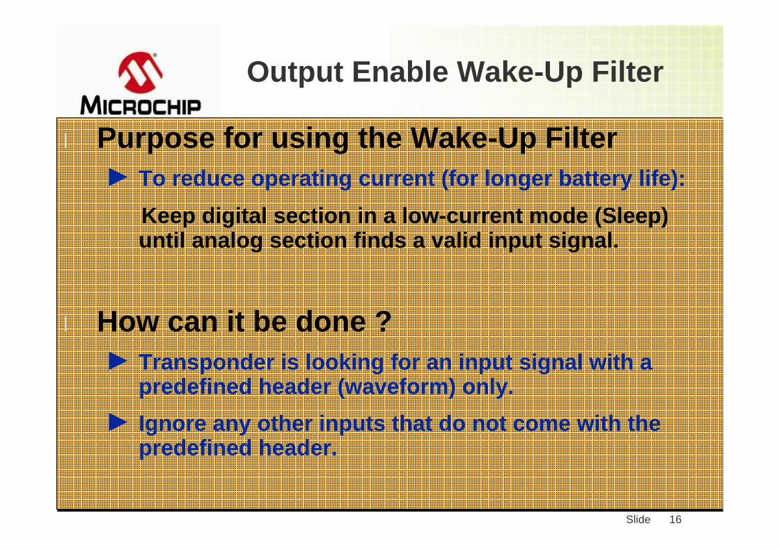
Output Enable Wake-Up Filter
l Purpose for using the Wake-Up Filter► To reduce operating current (for longer battery life):
Keep digital section in a low-current mode (Sleep) until analog section finds a valid input signal.
l How can it be done ?► Transponder is looking for an input signal with a
predefined header (waveform) only. ► Ignore any other inputs that do not come with the
predefined header.

© 2005 Microchip Technology Incorporated. All Rights Reserved. Class Slide 17
Wake-Up Filter
Gap
Start Bit
AGC
Data FieldDemodulated Output
Input Signal WaveformProgrammable Wake-Up Filter
Data FieldStabilization
Time

© 2005 Microchip Technology Incorporated. All Rights Reserved. Class Slide 18
Output When Wake-Up Filter Enabled
Input Signal
DemodulatedOutput
© 2005 Microchip Technology Incorporated. All Rights Reserved. Class Slide 19
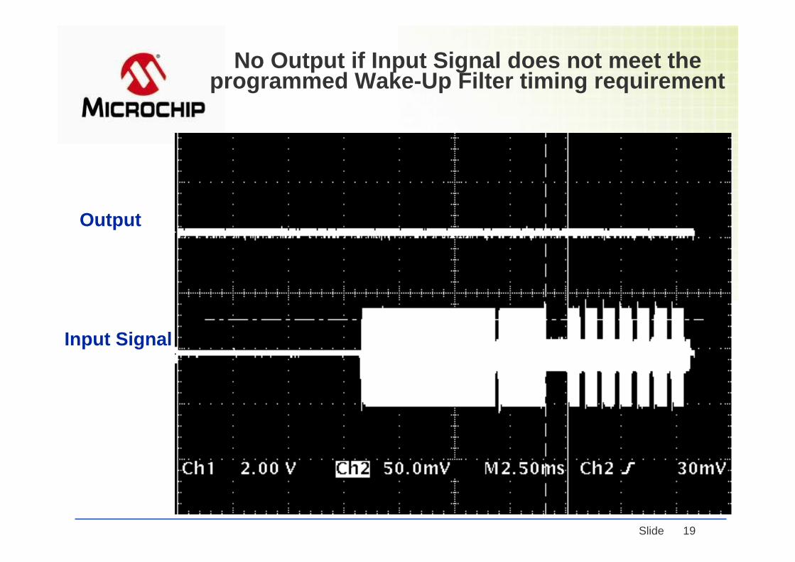
No Output if Input Signal does not meet the programmed Wake-Up Filter timing requirement
Input Signal
Output

© 2005 Microchip Technology Incorporated. All Rights Reserved. Class Slide 20
Output When Wake-Up Filter Disabled
Input Signal
DemodulatedOutput

© 2005 Microchip Technology Incorporated. All Rights Reserved. Class Slide 21
4. Amplitude Sensitivity
and Modulation Depth
4. Amplitude Sensitivity
and Modulation Depth

© 2005 Microchip Technology Incorporated. All Rights Reserved. Class Slide 22
RF Pulses in Near Field
τe
Long Decaying Time
In near field, it is very difficult to achieve 100 % modulation depth unless transmitting data with very slow data rate.
© 2005 Microchip Technology Incorporated. All Rights Reserved. Class Slide 23
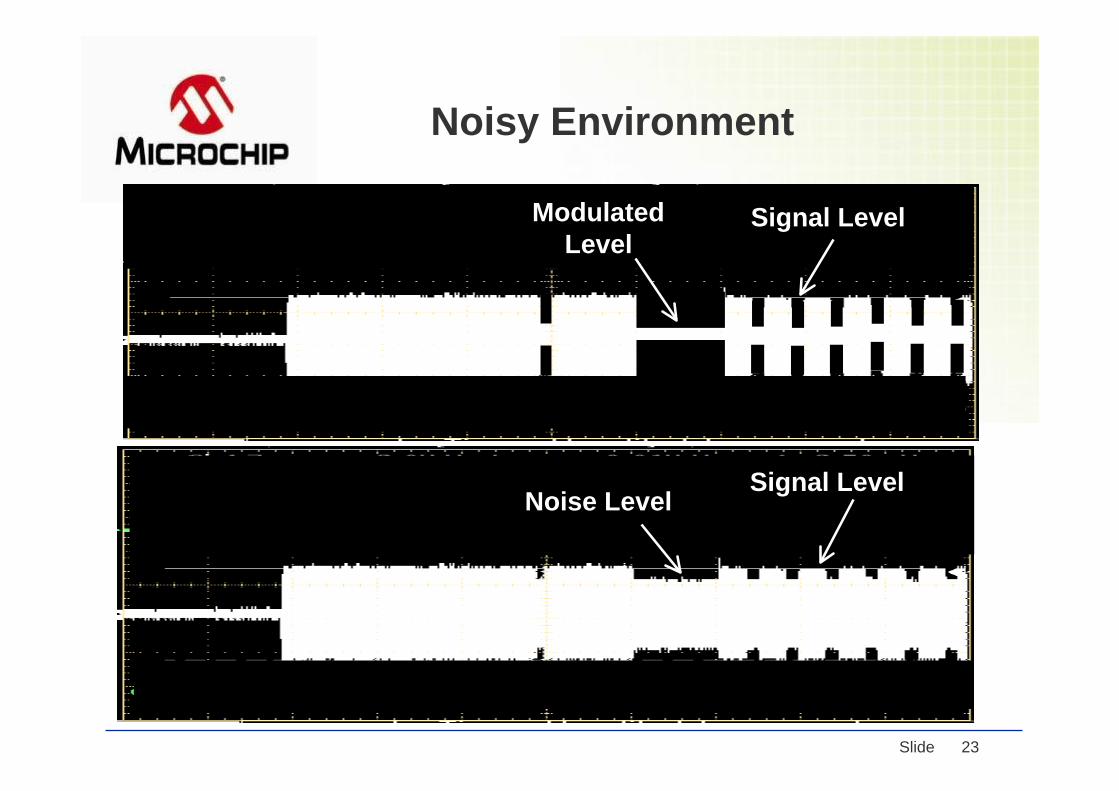
Noisy Environment
Noise Level Signal Level
Modulated Level
Signal Level

© 2005 Microchip Technology Incorporated. All Rights Reserved. Class Slide 24
Definition of Modulation Depth
B (5 mVPP) A (10 mVPP)
Modulation Depth =
A -B
A X 100 %
Pulsed Signal
(Microchip)
Modulation Depth =(Text Book)
A -B
X 100 %A + B
(50 %)
(33 %)
© 2005 Microchip Technology Incorporated. All Rights Reserved. Class Slide 25
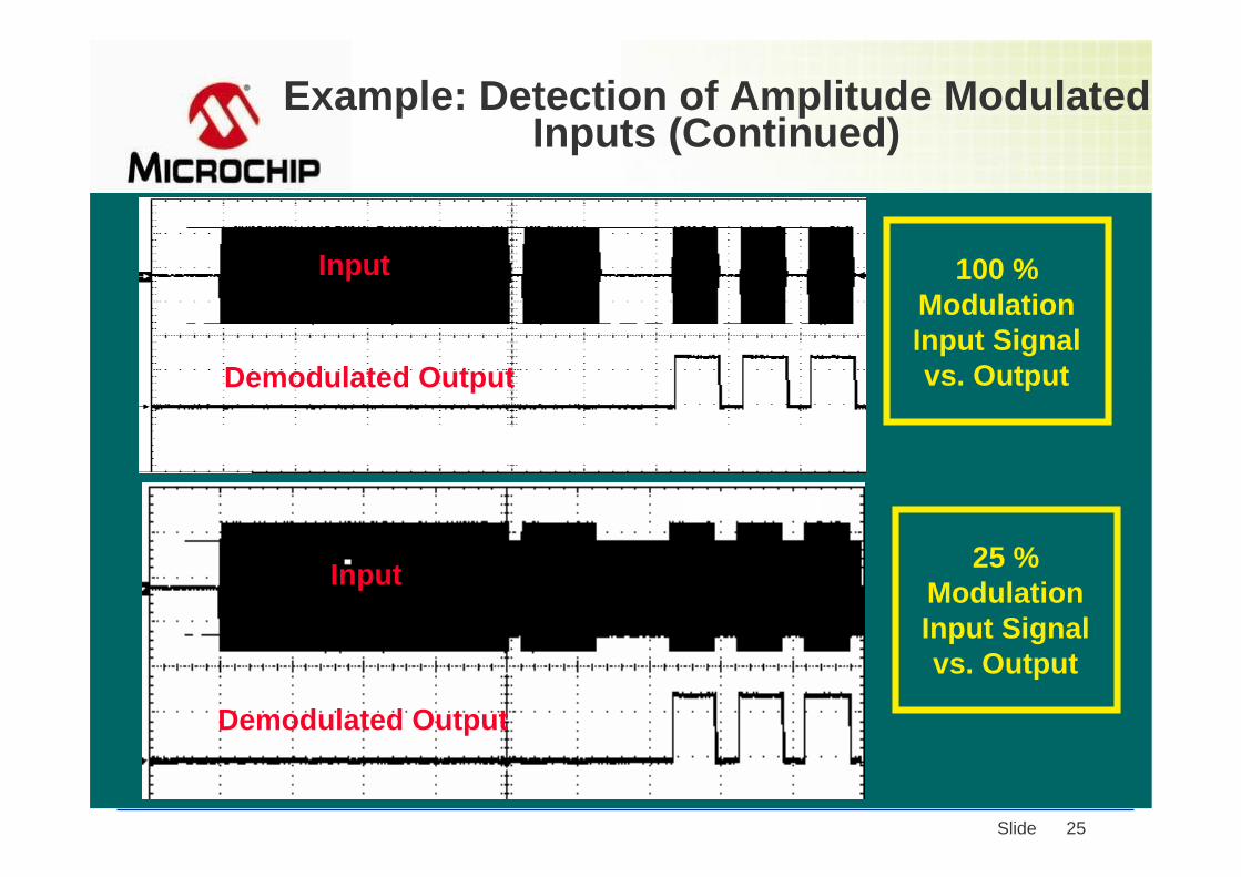
Example: Detection of Amplitude Modulated Inputs (Continued)
100 % Modulation Input Signal vs. Output
25 % Modulation Input Signal vs. Output
Demodulated Output
Input
Input
Demodulated Output

© 2005 Microchip Technology Incorporated. All Rights Reserved. Class Slide 26
5. Examples:
Smart Passive Keyless
Entry (PKE) System Design
5. Examples:
Smart Passive Keyless
Entry (PKE) System Design

© 2005 Microchip Technology Incorporated. All Rights Reserved. Class Slide 27
Example: Smart PKE Transponder with Batteryless and Battery Backup Circuits
UHF Transmitter
LCX
VBAT VDD
D1
D4
D3
D2
C1
LCcomRcom
R Lim
UHF Ant
1.8 V -5.5 V
PIC16F639LCY
LCZ
LCCOM
(Optional)

© 2005 Microchip Technology Incorporated. All Rights Reserved. Class Slide 28
Working System Requirements
● Transponder► LF Antenna(s)► UHF Transmitter► External Battery Back-up Circuit (optional)► Smart MCU and MCU Firmware
● Base Station► LF Transmitter► UHF Receiver► Antenna► MCU and MCU Firmware

© 2005 Microchip Technology Incorporated. All Rights Reserved. Class Slide 29
Parameters for Bi-Communication Distance
l Transponderè Antenna Tuning and Qè Antenna Orientation (use 3D
antenna)è Receiving Sensitivityè Modulation Depth of Input Signal è Data Rate
l Base Station è Output Powerè Receiving Sensitivity
Distance

© 2005 Microchip Technology Incorporated. All Rights Reserved. Class Slide 30
Antenna Design
● LF: 125 kHz ► Use LC Resonant Circuit
♦ Antenna Type: Air-Core or Ferrite-Core (1 -10 mH )♦ LC Resonant Frequency = Carrier Frequency of Base Station
♦ Range:< 1 meter for passive tag < 5 meters for active tag
● UHF: 315 -960 MHz► Use Dipole Antenna: Etched on PCB♦ Range
~ 5 meters for passive tag ~ 100 meters for active tag

© 2005 Microchip Technology Incorporated. All Rights Reserved. Class Slide 31
Magnetic Flux and Induced Antenna Voltage
))(2
( 2/3221
2
22 dSraNIa
dtdNdSB
dtdN
dtdNV o∫ ∫ +
−=•−=Φ
−=µ
απ
µ
cos2
2
1
13
221
o
o
NSQBfdtdIM
dtdI
rSaNN
≈
−≡
−=
N = Number of Turns of CoilS = Surface Area of Receiver Coilf = Frequency, Q = Quality Factor
Where: TX
C
tII o ωsin=
L
Transmitter Antenna
Magnetic Fields
Receiver Coil
I

© 2005 Microchip Technology Incorporated. All Rights Reserved. Class Slide 32
0
50
100
150
200
250
0 100 200 300 400 500
Distance (Cm)
Ant
enna
Coi
l Vol
tage
(Vpp
)
0
0.005
0.01
0.015
0.02
0.025
0 100 200 300 400 500
Distance (Cm)
Ante
nna
Coil
Volta
ge (V
pp)
Induced Antenna Voltage Over Distance
© 2005 Microchip Technology Incorporated. All Rights Reserved. Class Slide 33
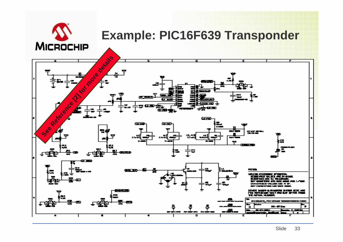
Example: PIC16F639 TransponderSee
Refe
rence
[2] f
or more
details

© 2005 Microchip Technology Incorporated. All Rights Reserved. Class Slide 34
Example: PIC16F639 Base StationSee
Refe
rence
[2] f
or more
details
© 2005 Microchip Technology Incorporated. All Rights Reserved. Class Slide 35
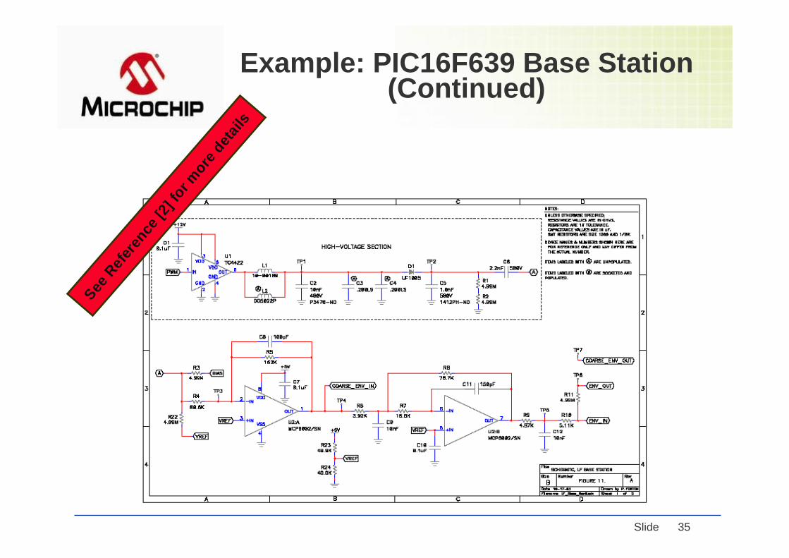
Example: PIC16F639 Base Station (Continued)
See R
efere
nce [2
] for m
ore deta
ils

© 2005 Microchip Technology Incorporated. All Rights Reserved. Class Slide 36
6. Conclusions6. Conclusions
● Systems can be built with a smart microcontroller
● Reliable Hands-Free OperationsRequire:
■ High LF Input Sensitivity■ Low Power Consumption
■ Smart Bi-directional Communications■ Low System Cost
■ Secure Data Encryption and Decryption
that can provide the solutions forthe above requirements.

© 2005 Microchip Technology Incorporated. All Rights Reserved. Class Slide 37
7. References
l [1] PIC12F635/16F636/16F639 Data Sheet, Microchip Technology Inc.
l [2] Microchip Application Notes: AN959, TB088, AN710, and AN912, Microchip Technology Inc.
l [3] Introduction to Radio Frequency Design, by W. H. Hayward, Prentice Hall, 1982.
l [4] Wireless Digital Communications: Design and Theory, by Tom McDermott, Tucson Amateur Packet Radio Corporation, 1998.
l [5] Short Range Wireless Communications, by Alan Bensky, LLH Technology Publishing, 2000.
© 2005 Microchip Technology Incorporated. All Rights Reserved. Class Slide 38
Key Web Sites for RF Design References
l Microchip : www.microchip.coml FCC: www.fcc.govl European Radio Comm Org: www.ero.dkl Euro Telecom Standards Inst.: www.etsi.orgl IEEE: www. ieee.orgl IEEE 802.15.4 Working Group:
http://grouper.ieee.org/group/802/15/index.htmll Home RF: www.homerf.orgl Bluetooth: www.bluetooth.coml Linx: www.linxtechnologies.com

© 2005 Microchip Technology Incorporated. All Rights Reserved. Class Slide 39
Thank You!Thank You!
The Microchip name and logo, KEELOQ, PIC and The Microchip name and logo, KEELOQ, PIC and PICmicroPICmicro are registered trademarks of Microchip are registered trademarks of Microchip Technology Incorporated in the U.S.A. and other countries. AllTechnology Incorporated in the U.S.A. and other countries. All other trademarks mentioned herein are other trademarks mentioned herein are property of their respective companies. property of their respective companies. ©©2005 2005 MicrochipTechnologyMicrochipTechnology Incorporated. All rights reserved.Incorporated. All rights reserved.