the removedebris adr mission: preparing for an ... · the removedebris adr mission: preparing for...
TRANSCRIPT

THE REMOVEDEBRIS ADR MISSION: PREPARING FOR ANINTERNATIONAL SPACE STATION LAUNCH
Jason L. Forshaw(1), Guglielmo S. Aglietti(1), Thierry Salmon(2), Ingo Retat a(3), ChristopherBurgess b(3), Thomas Chabot c(3), Aurelien Pisseloup d(3), Andy Phipps(4), Cesar Bernal f (5),
Francois Chaumette g(5), Alexandre Pollini h(5), and Willem H. Steyn i(5)
(1)Surrey Space Centre, University of Surrey, Guildford, UK. Email: [email protected](2)Airbus Safran Launchers, Bordeaux, France
(3)Airbus Defence and Space (DS): a Bremen, Germany; b Stevenage, UK; c Toulouse, France; d Bordeaux,France
(4)Surrey Satellite Technology Limited (SSTL), Guildford, UK
(5)f Innovative Solutions In Space (ISIS), Netherlands; g Inria, France; h CSEM, Switzerland; i StellenboschUniversity, South Africa
ABSTRACT
Since the beginning of the space era, a significantamount of debris has progressively been generatedin space. Active Debris Removal (ADR) missionshave been suggested as a way of limiting and control-ling future growth in orbital space debris by activelysending up vehicles to remove debris. The EC FP7RemoveDebris mission, which started in 2013, drawson the expertise of some of Europe’s most prominentspace institutions in order to demonstrate key ADRtechnologies in a low-cost ambitious manner.
The RemoveDebris mission launches to the Interna-tional Space Station (ISS) in late 2017 where shortlyafter it will be deployed via the NanoRacks Kabersystem into an orbit of around 400 km. The missionwill perform its core demonstrations sequentially,utilising two CubeSats as artificial debris targets:net capture, harpoon capture, vision-based naviga-tion, dragsail de-orbiting. The mission comes to anend in 2018 with all space entities having naturallyde-orbited.
This paper is split into the following parts: (a) anoverview of the mission segments, (b) a discussion onlaunch procedures, (c) an overview of the operationssequence and demonstration timelines. The secondsection will focus on the specifics of the launch viaNanoRacks and respective the NASA safety reviews.The third section will outline the planned operationaltimelines for the payloads. There will be a focuson what demonstrations will be performed and whattypes of data will be collected.
The RemoveDebris mission aims to be one of theworld’s first in-orbit demonstrations of key technolo-gies for active debris removal and is a vital prerequi-
site to achieving the ultimate goal of a cleaner Earthorbital environment.
Keywords: debris removal; ADR; deorbiting; net;harpoon; vision-based navigation; dragsail.
1. INTRODUCTION
RemoveDebris is a low cost mission perform-ing key active debris removal (ADR) technology
demonstrations including the use of a net, a harpoon,vision-based navigation (VBN) and a dragsail in a re-alistic space operational environment, due for launchin 2017. For the purposes of the mission CubeSatsare ejected then used as targets instead of real spacedebris, which is an important step towards a fullyoperational ADR mission. This paper examines themission launch specifics and starts reviewing the op-erations timeline of the mission and the methodol-ogy in which the in-orbit demonstrations will be per-formed.
The project consortium partners with their respon-sibilities are given in Table 1.
1.1. Literature
One of the most active in the field of debris removalis the European Space Agency (ESA). ESA has pro-duced a range of CleanSpace roadmaps, two of whichfocus on (a) space debris mitigation and (b) tech-nologies for space debris remediation. A main partof these roadmaps is e.Deorbit, a programme span-ning a host of phase studies examining removing a
Proc. 7th European Conference on Space Debris, Darmstadt, Germany, 18–21 April 2017, published by the ESA Space Debris Office
Ed. T. Flohrer & F. Schmitz, (http://spacedebris2017.sdo.esoc.esa.int, June 2017)
2
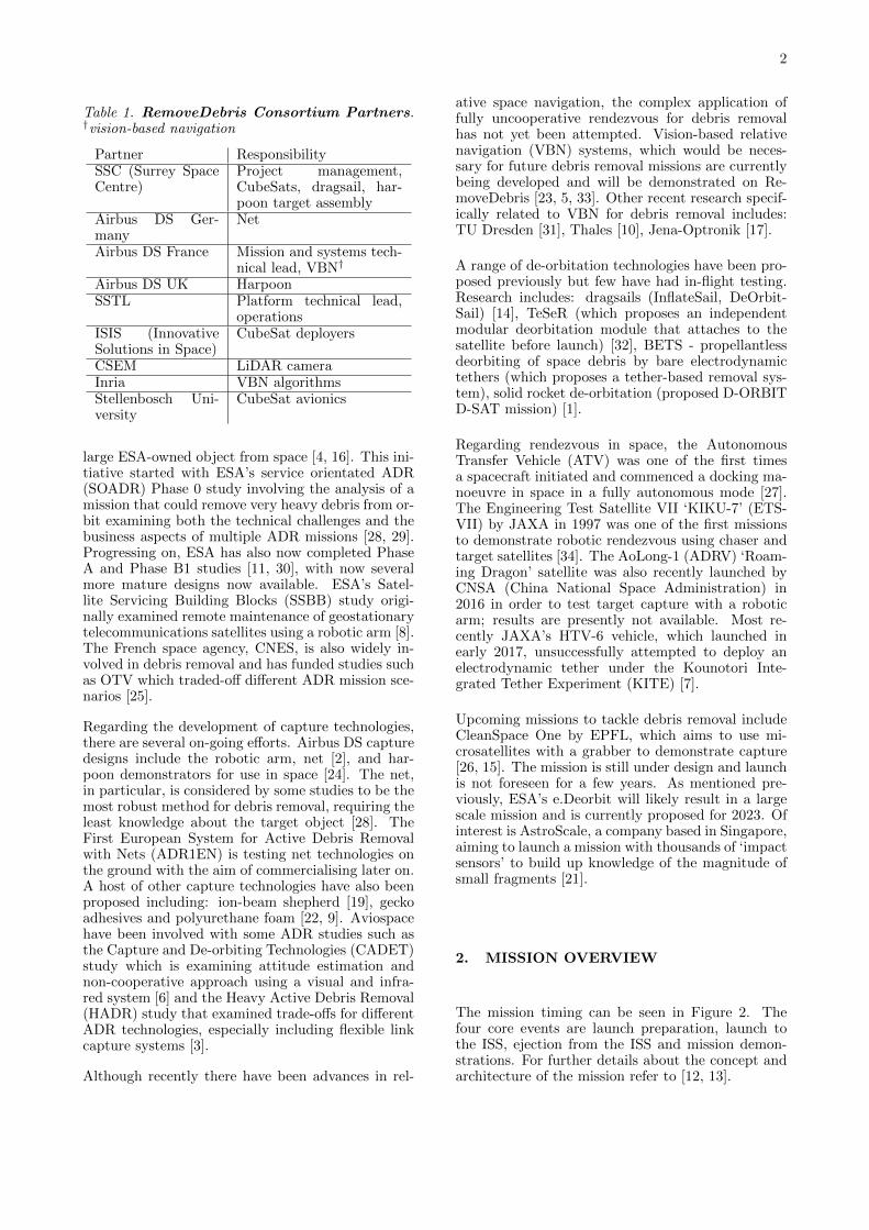
Table 1. RemoveDebris Consortium Partners.†vision-based navigation
Partner ResponsibilitySSC (Surrey SpaceCentre)
Project management,CubeSats, dragsail, har-poon target assembly
Airbus DS Ger-many
Net
Airbus DS France Mission and systems tech-nical lead, VBN†
Airbus DS UK HarpoonSSTL Platform technical lead,
operationsISIS (InnovativeSolutions in Space)
CubeSat deployers
CSEM LiDAR cameraInria VBN algorithmsStellenbosch Uni-versity
CubeSat avionics
large ESA-owned object from space [4, 16]. This ini-tiative started with ESA’s service orientated ADR(SOADR) Phase 0 study involving the analysis of amission that could remove very heavy debris from or-bit examining both the technical challenges and thebusiness aspects of multiple ADR missions [28, 29].Progressing on, ESA has also now completed PhaseA and Phase B1 studies [11, 30], with now severalmore mature designs now available. ESA’s Satel-lite Servicing Building Blocks (SSBB) study origi-nally examined remote maintenance of geostationarytelecommunications satellites using a robotic arm [8].The French space agency, CNES, is also widely in-volved in debris removal and has funded studies suchas OTV which traded-off different ADR mission sce-narios [25].
Regarding the development of capture technologies,there are several on-going efforts. Airbus DS capturedesigns include the robotic arm, net [2], and har-poon demonstrators for use in space [24]. The net,in particular, is considered by some studies to be themost robust method for debris removal, requiring theleast knowledge about the target object [28]. TheFirst European System for Active Debris Removalwith Nets (ADR1EN) is testing net technologies onthe ground with the aim of commercialising later on.A host of other capture technologies have also beenproposed including: ion-beam shepherd [19], geckoadhesives and polyurethane foam [22, 9]. Aviospacehave been involved with some ADR studies such asthe Capture and De-orbiting Technologies (CADET)study which is examining attitude estimation andnon-cooperative approach using a visual and infra-red system [6] and the Heavy Active Debris Removal(HADR) study that examined trade-offs for differentADR technologies, especially including flexible linkcapture systems [3].
Although recently there have been advances in rel-
ative space navigation, the complex application offully uncooperative rendezvous for debris removalhas not yet been attempted. Vision-based relativenavigation (VBN) systems, which would be neces-sary for future debris removal missions are currentlybeing developed and will be demonstrated on Re-moveDebris [23, 5, 33]. Other recent research specif-ically related to VBN for debris removal includes:TU Dresden [31], Thales [10], Jena-Optronik [17].
A range of de-orbitation technologies have been pro-posed previously but few have had in-flight testing.Research includes: dragsails (InflateSail, DeOrbit-Sail) [14], TeSeR (which proposes an independentmodular deorbitation module that attaches to thesatellite before launch) [32], BETS - propellantlessdeorbiting of space debris by bare electrodynamictethers (which proposes a tether-based removal sys-tem), solid rocket de-orbitation (proposed D-ORBITD-SAT mission) [1].
Regarding rendezvous in space, the AutonomousTransfer Vehicle (ATV) was one of the first timesa spacecraft initiated and commenced a docking ma-noeuvre in space in a fully autonomous mode [27].The Engineering Test Satellite VII ‘KIKU-7’ (ETS-VII) by JAXA in 1997 was one of the first missionsto demonstrate robotic rendezvous using chaser andtarget satellites [34]. The AoLong-1 (ADRV) ‘Roam-ing Dragon’ satellite was also recently launched byCNSA (China National Space Administration) in2016 in order to test target capture with a roboticarm; results are presently not available. Most re-cently JAXA’s HTV-6 vehicle, which launched inearly 2017, unsuccessfully attempted to deploy anelectrodynamic tether under the Kounotori Inte-grated Tether Experiment (KITE) [7].
Upcoming missions to tackle debris removal includeCleanSpace One by EPFL, which aims to use mi-crosatellites with a grabber to demonstrate capture[26, 15]. The mission is still under design and launchis not foreseen for a few years. As mentioned pre-viously, ESA’s e.Deorbit will likely result in a largescale mission and is currently proposed for 2023. Ofinterest is AstroScale, a company based in Singapore,aiming to launch a mission with thousands of ‘impactsensors’ to build up knowledge of the magnitude ofsmall fragments [21].
2. MISSION OVERVIEW
The mission timing can be seen in Figure 2. Thefour core events are launch preparation, launch tothe ISS, ejection from the ISS and mission demon-strations. For further details about the concept andarchitecture of the mission refer to [12, 13].

3
1 2 3 4 5
Fig. 1. Launch Sequence. This figure shows the launch sequences for the mission to the International SpaceStation (ISS). Courtesy: SpaceX, NanoRacks, NASA [20].
Launch Preparation (T0 - 2)- FRR (flight readiness review)
- Battery charging (main platform)
- Satellite shipped from EU to US
- Delivery to NASA for cargo integration
- Cargo integration on launcher
Launch to ISS (T0)- Launch
- Transfer and ISS docking
- Satellite transfer within ISS
- Satellite prepared by astronauts
Ejection from ISS (T0 + 1.5)- Satellite transfer via airlock and JRMS
- Separation from ISS
- LEOP
- Commissioning and testing
Demonstrations (T0 + 4)- In-orbit demonstrations (net, VBN,
harpoon, dragsail)
- De-orbiting
- End of mission
Fig. 2. High Level Mission Timing. High leveltiming on the mission where times are in months andrelative to the launch to the ISS (T0).
2.1. Mission Segments
Figure 3 shows the mission space segment for theproposed launch. Operations for the RemoveDebrismission will be carried out from SSTL’s Mission Op-erations Centre in Guildford. SSTL’s standard op-erations procedures will be used, which are compati-ble with the SSTL designed platform operational re-quirements and characteristics. The primary com-munications dish is at Guildford, with a backup atBordon; communications are at s-band level.
3. LAUNCH
The launch sequence for the RemoveDebris mission isan unconventional one. The solution uses NanoRacksas a supply agent to launch the final flight platformto the International Space Station (ISS) abroad aSpaceX cargo or Orbital ATK’s Cygnus rocket. Themass of the platform, 100 kg, represents a new busi-ness line, in that past NanoRacks launches of systemsfrom the ISS were of a much lower mass. The launchis expected to be in late 2017, but the launch man-ifest and weather disruptions will dictate the finallaunch date.
The use of the ISS scenario, launching to approxi-mately 380 km, provides greater confidence to licens-ing agencies as to the mission safety, as if there wereany issues, all the items would de-orbit very quickly.[12] and [18] give more information about the orbitallifetime of the objects calculated using both STELAand DRAMA, specialist end-of-life tools. They showthat the main platform de-orbits within 2 years, evenin case of the dragsail not deploying; smaller items,such as the CubeSats, de-orbit within a matter ofmonths. Thus no further space debris is generated.
3.1. Launch Sequence
The launch sequence can be seen in Figure 1. Beforelaunch (1), the platform is packaged into a crew orcargo transfer bag (CTB) inside a foam ‘clam shell’which protects it. After the bag is launched to theISS (2), the bag is unpacked by astronauts that in-stall the platform on to the Japanese experimentmodule (JEM) air lock (3). The air lock then de-presses and the slide table extends. The platform isgrappled by the JRMS, a robotic arm system (4). Fi-nally, the robotic arm positions and releases the plat-form into space (5), where commissioning and mainoperations of the mission can commence. Naturally,the ejection trajectory ensures that the satellite willnot intersect the ISS orbit at a later time.

4
Fig. 3. Overview of Mission Segments. This figure shows the three mission segments: launch, space,ground. From [12].
N1 N2 N3 N4
V1 V2 V3
H1 H2 H3 H4
D1 D2 D3
Fig. 4. Demonstration Sequence. This figure shows the demonstration sequences for the net (N1 to N4),VBN (V1 to V3), harpoon (H1 to H4) and dragsail (D1 to D3).

5
4. IN-ORBIT DEMONSTRATIONS (IOD)
4.1. Overview of Demonstrations
The four core mission demonstrations are shown inFigure 4. The net sequence is: (N1) DS-1 CubeSatejection, (N2) inflatable structure inflation, (N3) netfiring, (N4) net capture. The VBN sequence is: (V1)DS-2 CubeSat ejection, (V2) DS-2 drifts away, (V3)VBN system collects data. The harpoon sequenceis: (H1) harpoon target plate extended, (H2) targetplate reaches end, (H3) harpoon firing, (H4) harpooncapture. The dragsail sequence is: (D1) inflatablemast deploys, (D2) sail starts deployment, (D3) sailfinishes deployment.
4.2. Net Demonstration
The proposed net demonstration sequence can beseen in Figure 5. The demonstration starts withchecking the platform is ready to start the demon-stration, and charging and turning on relevant plat-form services. Although the VBN demonstrationcomes after the net demonstration, the VBN requirescalibration during the net demonstration and thusthe full VBN image capture, transfer and downloadchain is performed to ensure the VBN is ready. ThePIU (payload interface unit) on the platform is usedto collect and process payload data. Part of the ini-tial checks are that the supervision cameras haveclear images - incorrect platform attitudes or poorlighting conditions (location in orbit) could meanimages are obscured or too light or dark. There istherefore an opportunity to correct these before thedemonstration begins.
On starting the main experiment the 3 platformsupervision cameras activate and record the entiredemonstration. At T0, the ISIPOD door opens re-leasing and translating the CubeSat into a lockedposition outside the ISIPOD. A timer cuts the CRS(CubeSat Release System) and the CubeSat is re-leased. Shortly after, the DS-1 inflatable (via theCGGs) is inflated (Fig 4-N2), and the net is ejectedto capture DS-1 (Fig 4-N3). The experiment closeswith collection and download to Earth of the VBNand supervision cameras data. The net and DS-1naturally de-orbit at a rapid rate due to the low al-titude.
The main data collected in this experiment is thevideo of the experiment (from 3 sources). Varioustelemetry can also be acquired from the platform andthe initial VBN experiment provides additional datasources.
Demo Opening- Query platform status and whether to start
experiment (T0 - 42 hr)
- Start charging DS-1 and net capacitors
- Point platform to nadir
- Turn on platform services (2 x PIUs, 3 x
supervision cameras, 2 x VBN cameras) (T0 -
21 hr)
VBN Test Phase- Record images from VBN, transfer to PIU
and download to Earth (T0 - 18 hr)
- Ensure good images and fully charged
devices
- Upload camera parameters (T0 - 6 hr)
CubeSat Ejection- Point platform to start attitude (T0 - 1 hr)
- Start cameras & VBN recording (T0 - 5 s)
- Activate ISIPOD and net timer (T0)
- CRS cuts, releases DS-1 (T0 + 65 s)
Net Ejection- DS-1 inflatable deploys (T0 + 100 s)
- Net switches 1 and 2 activate (T0 + 191 s)
- Platform AOCS activated for attitude
disturbance (T0 + 192 s)
Demo Closing- Stop supervision cameras & VBN recording
(T0 + 400 s)
- Terminate net devices (T0 + 500 s)
- Transfer VBN data to PIU and download to
Earth (T0 + 3 days)
- End demonstration (T0 + 20 days)
Fig. 5. Net Operations Sequence. Relative toT0, ISIPOD activation (and start of CubeSat trans-lation). Sequence is a simplification of the full se-quence and is subject to change.
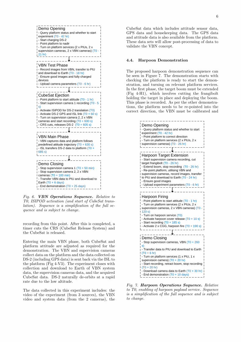
4.3. VBN Demonstration
The proposed VBN demonstration sequence can beseen in Figure 6. The demonstration starts withchecking the platform is ready to start the demon-stration, and charging and turning on relevant plat-form services. For clarity, there are 3 supervisioncameras on the platform and 2 VBN cameras (3d,2d) but in the VBN demonstration only 2 of thesupervision cameras are used. Similar to the netdemonstration, the VBN requires a calibration andtest phase where the full VBN image capture, trans-fer and download chain is tested.
At T0, the ISIPOD door opens releasing and trans-lating the CubeSat into a locked position outside theISIPOD. Different to the net demonstration, DS-2 isgiven time here to flip open the solar panels, startits on-board services, acquire a GPS lock and ini-tiate the inter-satellite link between DS-2 and theplatform (ISL) (Fig 4-V1). The VBN cameras start
6
Demo Opening- Query platform status and whether to start
experiment (T0 - 42 hr)
- Start charging DS-2
- Point platform to nadir
- Turn on platform services (2 x PIUs, 2 x
supervision cameras, 2 x VBN cameras) (T0 -
21 hr)
VBN Test Phase- Record images from VBN, transfer to PIU
and download to Earth (T0 - 18 hr)
- Ensure good images and fully charged
devices
- Upload camera parameters (T0 - 6 hr)
CubeSat Ejection- Point platform to start attitude (T0 - 1 hr)
- Start supervision camera 1 recording (T0 - 5
s)
- Activate ISIPOD for DS-2 translation (T0)
- Activate DS-2 GPS and ISL link (T0 + 60 s)
- Turn on supervision camera 2, 2 x VBN
cameras and start recording (T0 + 600 s)
- CRS cuts, releases DS-2 (T0 + 605 s)
VBN Main Phase- VBN captures data and platform follows
predefined attitude trajectory (T0 + 630 s)
- ISL transfers DS-2 data to platform (T0 +
685 s)
Demo Closing- Stop supervision camera 1 (T0 + 50 min)
- Stop supervision camera 2, 2 x VBN
cameras (T0 + 100 min)
- Transfer VBN data to PIU and download to
Earth (T0 + 6 days)
- End demonstration (T0 + 25 days)
Fig. 6. VBN Operations Sequence. Relative toT0, ISIPOD activation (and start of CubeSat trans-lation). Sequence is a simplification of the full se-quence and is subject to change.
recording from this point. After this is completed, atimer cuts the CRS (CubeSat Release System) andthe CubeSat is released.
Entering the main VBN phase, both CubeSat andplatform attitude are adjusted as required for thedemonstration. The VBN and supervision camerascollect data on the platform and the data collected onDS-2 (including GPS data) is sent back via the ISL tothe platform (Fig 4-V3). The experiment closes withcollection and download to Earth of VBN systemdata, the supervision cameras data, and the acquiredCubeSat data. DS-2 naturally de-orbits at a rapidrate due to the low altitude.
The data collected in this experiment includes: thevideo of the experiment (from 3 sources), the VBNvideo and system data (from the 2 cameras), the
CubeSat data which includes attitude sensor data,GPS data and housekeeping data. The GPS dataand attitude data is also available from the platform.These data sets will allow post-processing of data tovalidate the VBN concept.
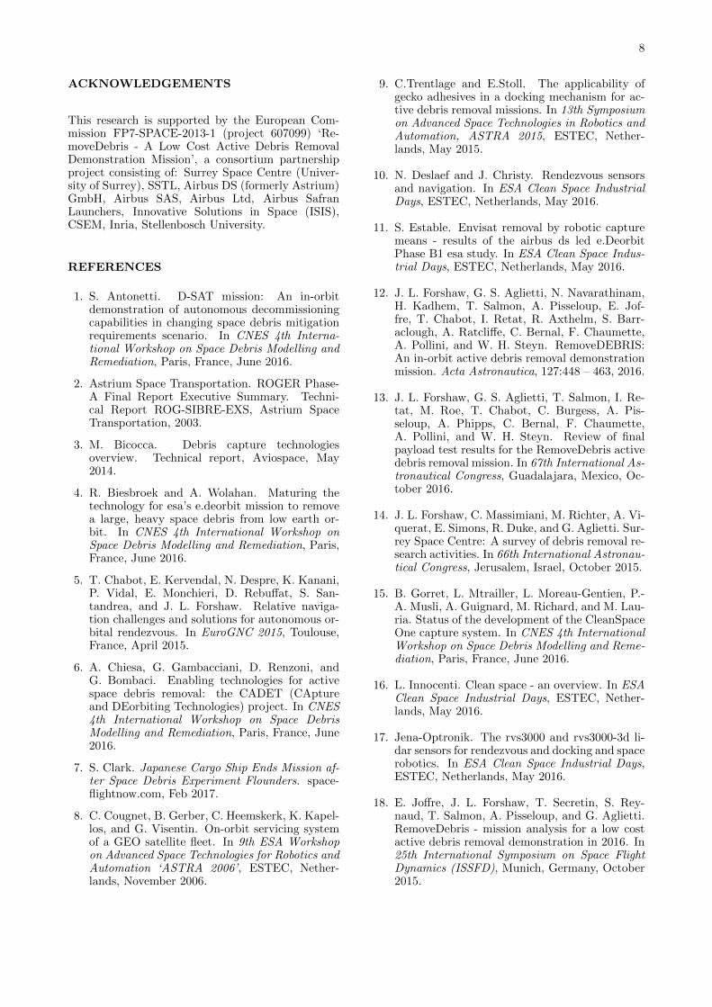
4.4. Harpoon Demonstration
The proposed harpoon demonstration sequence canbe seen in Figure 7. The demonstration starts withchecking the platform is ready to start the demon-stration, and turning on relevant platform services.In the first phase, the target boom must be extended(Fig 4-H1), which involves cutting the frangiboltholding the target in place and deploying the boom.This phase is recorded. As per the other demonstra-tions, the platform needs to be re-pointed into thecorrect direction, the VBN must be calibrated and
Demo Opening- Query platform status and whether to start
experiment (T0 - 42 hr)
- Point platform to correct direction
- Turn on platform services (2 x PIUs, 2 x
supervision cameras) (T0 - 26 hr)
Harpoon Target Extension- Start supervision camera recording, cut
target frangibolt (T0 - 26 hr)
- Extend boom, stop recording (T0 - 26 hr)
- Re-point platform, utilising VBN and
supervision cameras, record images, transfer
to PIU and download to Earth (T0 - 24 hr)
- Ensure good images
- Upload experiment parameters (T0 - 6 hr)
Harpoon Firing- Point platform to start attitude (T0 - 1 hr)
- Turn on platform services (2 x PIUs, 2 x
supervision cameras, 2 x VBN cameras) (T0 -
120 s)
- Turn on harpoon service (T0)
- Activate harpoon cover release (T0 + 10 s)
- Start recording (T0 + 185 s)
- Activate 2 x CGG, harpoon fire (T0 + 190 s)
Demo Closing- Stop supervision cameras, VBN (T0 + 260
s)
- Transfer data to PIU and download to Earth
(T0 + 6 hr)
- Turn on platform services (1 x PIU, 1 x
supervision camera) (T0 + 20 hr)
- Start recording, retract boom, stop recording
(T0 + 20 hr)
- Download camera data to Earth (T0 + 30 hr)
- End demonstration (T0 + 10 days)
Fig. 7. Harpoon Operations Sequence. Relativeto T0, enabling of harpoon payload service. Sequenceis a simplification of the full sequence and is subjectto change.

7
the supervision camera images checked ready for themain experiment.
In the main part of the demonstration, the platformservices are re-enabled ready for the firing. At T0,the harpoon payload service is turned on (this is notthe point at which the harpoon fires). Shortly afterthe harpoon protection cover is released (Fig 4-H3),recording is started and the 2 CGGs (cold gas gen-erators) that fire the harpoon are activated. Theharpoon aims to impact the target plate (Fig 4-H4).
The experiment closes with collection and down-load to Earth of VBN system data and the supervi-sion cameras data. Before finishing the demonstra-tion, the harpoon is retracted slightly (which is alsorecorded).
The main data collected in this experiment is thevideo of the experiment (from 2 sources). Varioustelemetry can also be acquired from the platform andthe initial VBN experiment provides additional datasources. A thermal sensor is also embedded in theharpoon target assembly.
4.5. Dragsail Demonstration
The proposed dragsail demonstration sequence canbe seen in Figure 8. The demonstration starts likethe other 3 to check whether the platform and pay-loads are in a suitable position to start the demon-stration. The supervision cameras are activated andthe dragsail power switches are activated at T0 (thisis not the point at which the dragsail starts deploy-ment). Shortly after the dragsail burnwire is cut toenable the mast to deploy, the boom venting valveis closed (see [13] for more information), and the 2CGGs are activated to inflate the mast. After this,the deployment motors are activated to unfurl thesail and carbon fibre booms. The experiment closeswith the download of supervision camera data toEarth. After the dragsail is deployed, the platformwill de-orbit at an accelerated rate. Due to the sizeof the sail, the platform does not guarantee unhin-dered communication or full power integrity (due topotential overlap of solar panels) after deployment;assessment of these is part of the demonstration.
The main data collected in this experiment is videofrom 2 camera sources. Various telemetry can also beacquired from the platform. In particular, the influ-ence of the deployed dragsail on the platform can beassessed through attitude (and generic AOCS) data,power data and communications systems data. Theplatform de-orbit trajectory can be tracked from theground and this can be compared with theoreticalsimulations of the de-orbit rate without a sail.
Demo Opening- Query platform status and whether to start
experiment (T0 - 18 hr)
- Point platform to start attitude
- Turn on platform services (2 x PIUs, 2 x
supervision cameras) (T0 – 60 s)
Dragsail Deployment- Start cameras recording (T0 - 30 s)
- Turn on dragsail service (T0)
- Cut dragsail burnwire protection (T0 + 15 s)
- Close boom valve and activate 2 x CGGs to
deploy inflatable mast (T0 + 60 s)
- Activate sail deployment motor (T0 + 120 s)
Demo Closing- Compensate for platform attitude
disturbances (T0 + 120 s)
Stop supervision cameras (T0 + 250 s)
- Terminate net devices (T0 + 500 s)
- Download camera data to Earth (T0 + 30 hr)
- End demonstration (T0 + 10 days)
Fig. 8. Dragsail Operations Sequence. Relativeto T0, enabling of dragsail payload service. Sequenceis a simplification of the full sequence and is subjectto change.
5. CONCLUSIONS
RemoveDebris is aimed at performing key ADR tech-nology demonstrations (e.g capture, deorbiting) rep-resentative of an operational scenario during a low-cost mission using novel key technologies for futuremissions in what promises to be one of the firstADR technology missions internationally. The mis-sion aims to be the first mission to demonstrate theuse of a harpoon and net in space for debris capture,and the first use of CubeSats as ‘artificial debris’ tar-gets. Additionally, the mission will be the world’sfirst 100 kg satellite to be launched from the ISS.
This paper has presented an overview of the missionsequence, the launch procedure and sequence usedfor the mission, and the planned experimental time-lines and operations for various payloads.
The key ADR technologies include the use of netand harpoon to capture targets, vision-based navi-gation to target debris and a dragsail for deorbiting.Although this is not a fully-edged ADR mission asCubeSats are utilised as artificial debris targets, theproject is an important step towards a fully opera-tional ADR mission; the mission proposed is a vi-tal prerequisite in achieving the ultimate goal of acleaner Earth orbital environment.
8
ACKNOWLEDGEMENTS
This research is supported by the European Com-mission FP7-SPACE-2013-1 (project 607099) ‘Re-moveDebris - A Low Cost Active Debris RemovalDemonstration Mission’, a consortium partnershipproject consisting of: Surrey Space Centre (Univer-sity of Surrey), SSTL, Airbus DS (formerly Astrium)GmbH, Airbus SAS, Airbus Ltd, Airbus SafranLaunchers, Innovative Solutions in Space (ISIS),CSEM, Inria, Stellenbosch University.
REFERENCES
1. S. Antonetti. D-SAT mission: An in-orbitdemonstration of autonomous decommissioningcapabilities in changing space debris mitigationrequirements scenario. In CNES 4th Interna-tional Workshop on Space Debris Modelling andRemediation, Paris, France, June 2016.
2. Astrium Space Transportation. ROGER Phase-A Final Report Executive Summary. Techni-cal Report ROG-SIBRE-EXS, Astrium SpaceTransportation, 2003.
3. M. Bicocca. Debris capture technologiesoverview. Technical report, Aviospace, May2014.
4. R. Biesbroek and A. Wolahan. Maturing thetechnology for esa’s e.deorbit mission to removea large, heavy space debris from low earth or-bit. In CNES 4th International Workshop onSpace Debris Modelling and Remediation, Paris,France, June 2016.
5. T. Chabot, E. Kervendal, N. Despre, K. Kanani,P. Vidal, E. Monchieri, D. Rebuffat, S. San-tandrea, and J. L. Forshaw. Relative naviga-tion challenges and solutions for autonomous or-bital rendezvous. In EuroGNC 2015, Toulouse,France, April 2015.
6. A. Chiesa, G. Gambacciani, D. Renzoni, andG. Bombaci. Enabling technologies for activespace debris removal: the CADET (CAptureand DEorbiting Technologies) project. In CNES4th International Workshop on Space DebrisModelling and Remediation, Paris, France, June2016.
7. S. Clark. Japanese Cargo Ship Ends Mission af-ter Space Debris Experiment Flounders. space-flightnow.com, Feb 2017.
8. C. Cougnet, B. Gerber, C. Heemskerk, K. Kapel-los, and G. Visentin. On-orbit servicing systemof a GEO satellite fleet. In 9th ESA Workshopon Advanced Space Technologies for Robotics andAutomation ‘ASTRA 2006’, ESTEC, Nether-lands, November 2006.
9. C.Trentlage and E.Stoll. The applicability ofgecko adhesives in a docking mechanism for ac-tive debris removal missions. In 13th Symposiumon Advanced Space Technologies in Robotics andAutomation, ASTRA 2015, ESTEC, Nether-lands, May 2015.
10. N. Deslaef and J. Christy. Rendezvous sensorsand navigation. In ESA Clean Space IndustrialDays, ESTEC, Netherlands, May 2016.
11. S. Estable. Envisat removal by robotic capturemeans - results of the airbus ds led e.DeorbitPhase B1 esa study. In ESA Clean Space Indus-trial Days, ESTEC, Netherlands, May 2016.
12. J. L. Forshaw, G. S. Aglietti, N. Navarathinam,H. Kadhem, T. Salmon, A. Pisseloup, E. Jof-fre, T. Chabot, I. Retat, R. Axthelm, S. Barr-aclough, A. Ratcliffe, C. Bernal, F. Chaumette,A. Pollini, and W. H. Steyn. RemoveDEBRIS:An in-orbit active debris removal demonstrationmission. Acta Astronautica, 127:448 – 463, 2016.
13. J. L. Forshaw, G. S. Aglietti, T. Salmon, I. Re-tat, M. Roe, T. Chabot, C. Burgess, A. Pis-seloup, A. Phipps, C. Bernal, F. Chaumette,A. Pollini, and W. H. Steyn. Review of finalpayload test results for the RemoveDebris activedebris removal mission. In 67th International As-tronautical Congress, Guadalajara, Mexico, Oc-tober 2016.
14. J. L. Forshaw, C. Massimiani, M. Richter, A. Vi-querat, E. Simons, R. Duke, and G. Aglietti. Sur-rey Space Centre: A survey of debris removal re-search activities. In 66th International Astronau-tical Congress, Jerusalem, Israel, October 2015.
15. B. Gorret, L. Mtrailler, L. Moreau-Gentien, P.-A. Musli, A. Guignard, M. Richard, and M. Lau-ria. Status of the development of the CleanSpaceOne capture system. In CNES 4th InternationalWorkshop on Space Debris Modelling and Reme-diation, Paris, France, June 2016.
16. L. Innocenti. Clean space - an overview. In ESAClean Space Industrial Days, ESTEC, Nether-lands, May 2016.
17. Jena-Optronik. The rvs3000 and rvs3000-3d li-dar sensors for rendezvous and docking and spacerobotics. In ESA Clean Space Industrial Days,ESTEC, Netherlands, May 2016.
18. E. Joffre, J. L. Forshaw, T. Secretin, S. Rey-naud, T. Salmon, A. Pisseloup, and G. Aglietti.RemoveDebris - mission analysis for a low costactive debris removal demonstration in 2016. In25th International Symposium on Space FlightDynamics (ISSFD), Munich, Germany, October2015.
9
19. M. Merino, E. Ahedo, C. Bombardelli, H. Ur-rutxua, J. Pelaez, and L. Summerer. Space de-bris removal with an ion beam shepherd satellite:target-plasma interaction. In 47th AIAA JointPropulsion Conference & Exhibit, San Diego,US, August 2011.
20. NanoRacks. Space station CubeSat deploymentservices. Technical report, February 2015.
21. N. Okada. ADRAS 1: Spacecrafts EOL solutionsand debris removal. In CNES 4th InternationalWorkshop on Space Debris Modelling and Reme-diation, Paris, France, June 2016.
22. A. Parness. Orbital debris removal with gecko-like adhesives; technology development and mis-sion design. In 66th International AstronauticalCongress, Jerusalem, Israel, October 2015.
23. A. Petit, E. Marchand, and K. Kanani. Trackingcomplex targets for space rendezvous and debrisremoval applications. In IEEE/RSJ Conferenceon Intelligent Robots and Systems, IROS’12, Vil-amoura, Portugal, October 2012.
24. A. Pisseloup, S. Estable, K. Pegg, E. Ferreira,R. Delage, J.-M. Pairot, T. Salmon, A. Ratcliffe,and M. Frezet. Airbus defence and space’s vi-sion and activities in active debris removal andon-orbit servicing. In CNES 4th InternationalWorkshop on Space Debris Modelling and Reme-diation, Paris, France, June 2016.
25. A. Pisseloup, T. Salmon, C. Cougnet, andM. Richard. ADR concepts from CNES fundedstudy OTV. In 64th International AstronauticalCongress, Beijing, China, September 2013.
26. M. Richard, L. Kronig, F. Belloni, S. Rossi,V. Gass, C. Paccolat, J. Thiran, S. Araomi,I. Gavrilovich, and H. Shea. Uncooperative ren-dezvous and docking for microsats: The case forCleanSpace One. In 6th International Confer-ence on Recent Advances in Space Technologies(RAST), Istanbul, Turkey, June 2013.
27. I. A. Sanchez, D. Paris, F. Allard, andN. Frischauf. The navigation and communica-tion systems for the Automated Transfer Vehicle.In IEEE 49th Vehicular Technology Conference,volume 2, pages 1187–1192, Jul 1999.
28. C. Saunders, J. L. Forshaw, V. J. Lappas,A. Chiesa, B. Parreira, and R. Biesbroek. Mis-sion and systems design for the debris removal ofmassive satellites. In 65th International Astro-nautical Congress, Toronto, Canada, September2014.
29. C. Saunders, J. L. Forshaw, V. J. Lappas,D. Wade, D. Iron, and R. Biesbroek. Businessand economic considerations for service orientedactive debris removal missions. In 65th Interna-tional Astronautical Congress, Toronto, Canada,September 2014.
30. M. Scheper. e.deorbit Phase B1 SystemOverview (OHB). In ESA Clean Space Indus-trial Days, ESTEC, Netherlands, May 2016.
31. A. Sonnenburg. Image recognition and process-ing for navigation (irpn). In ESA Clean Space In-dustrial Days, ESTEC, Netherlands, May 2016.
32. P. Voigt, C. Vogt, B. Barthen, H. Stokes, C. Un-derwood, A. Knoll, K. Ryden, M. Macdonald,E. Kerr, and et. al. TeSeR - technology for self-removal - a horizon 2020 project to ensure thepost-mission-disposal of any future spacecraft.In ESA Clean Space Industrial Days, ESTEC,Netherlands, May 2016.
33. A. Yol, E. Marchand, F. Chaumette, K. Kanani,and T. Chabot. Vision-based navigation in lowearth orbit. In i-SAIRAS 2016, Beijing, China,June 2016.
34. K. Yoshida. ETS-VII Flight Experiments ForSpace Robot Dynamics and Control, volume 271.Experimental Robotics VII, Springer, 2001.