the ornl automated orbital pipl welding systems
TRANSCRIPT
r « ^ w o % ^ *
ORNl-4830
THE ORNL AUTOMATED ORBITAL PIPL WELDING SYSTEMS
Peter P. Holz
MAS t_ ,d
•KTK8UTWU Of THIS OTCUMBfr IS IWUMITO
*;;>*:,".-
ax

>
BLANK PAGE
r^—«?W . ;- -^-w!--* —"^^f*«i>Li • ^ - ^ ? ^ H * ^ ^ ^ - r r - i s a » i f l f ^ r — '
Printed in the United States of America. Available from National Technical Information Servic?
U.S. Department of Commerce 5285 Port Royal Road. Springfield, Virginia 22151
Price: Printed Copy S3.00; Microfiche $0.9fi
This report was prepared as an account of work sponsored by the United States Government. Neither the United States nor the United States Atomic Energy Coitwnission, nor any of their employees, nor any of .hei r contractors, subcontractors, or th-»ir employees, makes any warranty, exprev. or imolied, or assumes any legal iiabifity or responsibility for the accuracy, completeness o. usefulness of any information, apparatus, product or proce-.s disclosed, or represents that its use would not infringe pri rely o*vned rights.
1
ORNL 4830 UC 80 Reactor T^chnoloqy
Contract YV-7405-eng-26
REACTOR DIVISION
THE ORNL AUTOMATED ORBITAL Pir VELP5NG SYSTEMS
Peter P. Hdz
JANUARY 1973
• H O T C I -This report was prepared as an scouat of sponsored by the United Sta*«s Government, Neither the United State* nor the United States Atomic Erergjr Commission, nor any of their employees, nor any of their contractors, subcontractors, or their employees, makes any warranty, express or impik*. of issvmw any 1«S>1 liability or responsibility for the accinscy, completeness or usefulness of iny information, apparatus, product or process disclosed, or represents that I s use would not infringe privately owned rights.
O A K h E N A T I O N A L L A B O R A T O R Y Oak R;dge, Tennessee 3 7 8 3 0
operated by U N I O N C A R B I D E CO . . ' O R A T I O N
for the U S A T O M I C E N E R G Y C O M M I S S I O N
Of T>UJ DOCOMEMT (Sffr lUWIB
Contents
ACKNOWLEDGMENTS v
ABSTRACT vii
1. INTRODUCTION AND SUMMARY I
2. FUNCTIONAL DESCRIPTION 3
3. SYSTEM COMPONENTS 6
Carriage 6
Welding Head 9
Power Supply 15
Pendant. Sensor, and Cables 18 Recorder 18
4. ELECTRICAL AND CONTROL SYSTEM 21
Programmer-Controller 21
Basic Subdivisions of Programmer Circuitry 21
Control Modes 22
Current Control 22
Pulse Current 23
Torch Oscillator 23
Tool Speed Control 23
Wire Feed Control and AVC 24
Arc Length Control (ALC> 24
Stubber Ci.cuit 25
Gas and Water Interlocks 25
Power Supplies and Power Buses 25
5. WELDING STUDIES, WELD JOINT DEVELOPMENT. AND WELDING SCHEDULE 26
6. WELDING SYSTEM OPERATIONS 30
Preweld Operations 30
Guidelines for Tacking Consumable Weld Inserts 31
Welding Techniques 32
Cleaning of Weld Beads 32
Detects 32
Repairs 32
Wt Id Schedule Data Sheets 32

BLANK PAGE
IV
Operational Procedure (ORNL Equipment) Checkoff List 32
Guidelines for the Welder-Operator's Visual Observation During Automated Welding 36
7 WELDING SYSTEM MAINTENANCE 37
8. OPERATOR TRAINING 37
9. CUTTING PREREQUISITES - PIPE CUT AND BEVEL PREPARATION DEVELOPMENT 38
10. COMMERCIAL I. 5. EQUIPMENT SOURCES FOR ORBITAL WELDING SYSTEMS 39
Appendix A. ORNL WELDING PROGRAMMER^ONTROLLER, CONTROLS AND FUNCTIONS 41
Appendix B. RECOMMENDED FORMAT FOR EST\BLISHING A WELDING PROCEDURE FOR AUTOMATIC WELDING 45
V
Acknowledgments
I wish to thank the Union Carbide Nuclear Division Purchasing Department and associates in various fields of endeavor at the Oak Ridge National Laboratory for their important contributions to the Automated Pipe Welding Program. Their combined effort contributed to the successful design, fabrication, development, and performance of our systems. Special thanks go to W. 0 . Harms, Director's Division; H. A. Nelms, General Engineering Division; W. A. Bird, C. C. Courtney, W. R. Miller, R. L.Moore,and R.W.Tucker, Instrumentation and Controls Division; G. M. Goodwin, T. R. Housley, G. C. Nelson, P. Patriarca, R. G. Shooster, G. M. Slaughter, and J. R. Weir, Jr., Metals and Ceramics Division; D. R. Frizzell and V. T. Houchin, Plant and Equipment Division; and S. R. Ashton, R. Blumberg, J. 0 . Brown, .1. R. Shugart, C M . Smith, Jr., I. Spiewak,
W. E. Thompson, and T. K. Walters, Reactor Division. 1 am particularly indebted to Bird, Goodwin, Houchin, Housley, Miller, Moore, Nelson, Slaughter, and Smith for their leadership, technical expertise,and teamwork, and to Brown, Thompson, and Moore for their assistance in the preparation of the report. I would also like to give special thanks to Myrtleen R. Sheldon for her painstaking efforts in final editing of the report.
Special thanks are also due D. C. King, Westinghouse-HanforH; R. L. Carter, W. J. Mariin,and A.C. Rediske, Bechtel-Hanford; and L. Birch, T. R. Brown,P. R. Kirk, J. Morgan, an**. J. E. Wilkins, TVA - Browns Ferry, for their cooperation in maintenance cf the equipment, field equipment improvements, ai.u reedback of valuable operational information and data.
Vll
Abstract
The Oak Ridge National Laboratory Has developed and successfully testea an improved automated welding system that has demonstrated reliable performance in making nuclear-quality welds on pipes from 3 to 16 in. in outside diameter. This equipment also shows promise for remote control of reactor maintenance operations of pipe cutting, beveling, and welding in high-radiation zones where personnel cannot enter.
The equipment was adapted from an orbiting automated pipe welding system originally designed for the Air Force by the North American Rockwell Corporation. Automation of the equipment permits complete welds to be made from preset programs fed into an electronic programmer-controller. ORNL developed improved controls that can sense changes from feedback signals and automatically adjust for pipe ovality and for ii regularities in the geometry and wall thickness at the prepared edges of the pipe joint. The automated controls also compensate for the difference between welding upward or downward in the 5G (pipe horizontal) position, as the carriage moves a gas tungsten-arc torch continuously around the pipe.
The equipment consists of an orbital horseshoe-shaped carriage that clamps onto a pipe and propels the welding apparatus around the circumference of a pipe in conjunction w«th an automatic welding programmer-
controller that constantly maintains all conditions necessary to produce code quality welds. The automated system has demonstrated that it can consistently produce high-quality welds, which also makes it attractive for direct welding applications in the construction of nuclear plants. To this end, development efforts were expanded to include pipe welding with the joint geometries most commonly used in the construction of stainless steei and carbon steel piping systems. Procedures were developed and shown to give good results for construction welding of p'pe jointi fitted with a consumable weld insert ring placed in the gap of the open pipe butt joint.
ORNL automated welding systems have been utilized at the Browns Ferry Nuclear Power Plant, being built by the Tennessee Valley Authority, and the Fast-Flux Test Facility, being built by Bechtel for Westinghouse at Hanford. At both installations the equipment has reliably produced nuclear-quality welds that meet ASME Boiler and Pressure Vessel Code, Section III, Nuclear Vessels, Section IX, Welding Qualifications, and applicable RDT standards. An experienced welder can learn to use the equipment in a few days ahd produce high-quality welds with practically zero defects about four times as fast as in manual welding.
1. Introduction
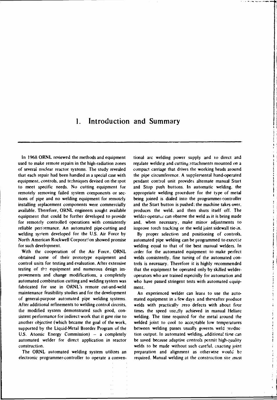
In 1968 ORNL reviewed the methods and equipment used to make remote repairs in the high-radiation zones of several nuclear reactor systems. The study revealed that each repair had been handled as a special case with equipment, controls, and techniques devised on the spot to meet specific needs. No cutting equipment for remotely removing failed system components or sections of pipe and no welding equipment for remotely installing replacement components were commercially available. Therefore, ORNL engineers sought available equipment that could be further developed to provide for remotely controlled operations with consistently reliable performance. An automated pipe-cutting and welding system developed for the U.S. Air Force by North American Rockwell Corporation showed promise for such development.
With the cooperation of the Air Force, ORNL obtained some of their prototype equipment and control units for testing and evaluation. After extensive testing of the equipment and numerous design improvements and change modifications, a completely automated combination cutting and welding system was fabricated for use in ORNL's remote cut-and-weld maintenance feasibility studies and for the development of general-purpose automated pipe welding systems. After additional refinements to welding control circuits, the modified system demonstrated such good, consistent performance for indirect work that it gave rise to another objective (which became the goal of the work, supported by the Liquid-Metal Breeder Program of the U.S. Atomic Energy Commission) - a completely automated welder for direct application in reactor construction.
The ORNL automated welding system utilizes an electronic programmer-controller to operate a conven-
and Summary
tional arc welding power supply and to direct and regulate welding and cutting attachments mounted on a compact carriage that drives the working heads around the pipe circumference. A supplemental hand-operated pendant control unit provides alternate manual Start and Stop push buttons. In automatic welding, the appropriate welding procedure for the type of metal being joined is dialed into the programmer-controller and the Start button is pushed: the machine takes over, produces the weld, and then shuts itself off. The welder-operator can observe the weld as it is being made and, when necessary, make minor adjustments to improve torch tracking or the weld joint sidewall tie-in.
By proper selection and positioning of controls, automated pipe welding can be programmed to execute welding equal to that of the best manual welders. In order for the automated equipment to make perfect welds consistently, fine tuning of the automated controls is necessary. Therefore it is highly recommended that the equipment be operated only by skilled welder-operators who are trained especially for automation and who have passed stringent tests with automated equipment.
An experienced welder can learn to use the automated equipment in ;« few days and thereafter produce welds with practically zero defects with about four times the speed usually achieved in manual Heliarc welding. The time required for the metai around the welded joint to cool to acceptable low temperatures between welding passes usually governs weld produc tion output. In automated welding, additional lime can be saved because adaptive controls permit high-quality welds to be made without such careful, exacting joint preparation and alignment as otherwise would bt required. Manual welding at the construction site must
2
be performed by specially qualified welders, which usually means that the construction contractor must conduct extensive training programs. In addition, nuclear-quality welding by hand is slow and is plagued by a high percentage of rejects.
Prototype systems of the modified desigr. developed by ORNL were fabricated by industrial vendors and then were assembled and proof tested by the Laboratory. We confirmed that the automated equipment with feedback circuits to adjust the controls during progress of the work can properly compensate for pipe ovality and for irregularity in the geometry and in the wall thickness at the prepared edges of the pipe joint. Tests showed that the automated equipment would accurately follow the programmed instructions and maintain the necessary conditions for high-quality welds. We evaluated several consumable weld insert ring shapes to be fitted into the gap of an open-butt joint to allow maximum tolerance for irregularities in the matching of pipe ends to be welded, and developed construction welding procedures for gas tu lgsien arc welding with Y cn*:vsection inserts and with Kellogg-type rectangular inserts. The equipment was shown to be capable of making continuous butt welds around the entire perimeter of the pipe that consistently met the requirements of the ASME Boiler and Pressure Vessel Code, Sections 111 and IX. and applicable RDT standards. The continuous perimeter weld offers a special advantage in that the errors and flaws that often result from welding starts and sops are eliminated.
ORNL built the prototype automated equipment to demonstrate the feasibility of using this system for nuclear-quality welds and also to prove the practicality of automated welding systems in actual daily use. We delivered automated welding systems to Westinghouse-Hanford. wliCP Bechtel Corporation personnel qualified the equipment for welding Fast-Flux Test Facility Project stainless steel pipes. Another automated welding system was delivered to the Tennessee Valley Authority at their Browns Ferry Nuclear Plant and is now in use primarily for welding carbon steel pipe in sizes up thr nigh 14 in. in diameter.
The metallurgical feus and welding research which established the optimum conditions and procedures for welding the pipe materials of nuclear systems were a viial part of the automated welding development program. The metallurgical and welding research determined the optimum values for all th? variables that must be controlled to obtain good welds and established detailed procedures to b° followed in welding different materials. The automat.d system was required to maintain these conditions and follow the procedures.
In particular, the electronic instrumentation and controls had to be sufficiently rugged to stand up under field construction use and still maintain accuracy in automatically following t!ie prede'ermir.ed welding procedure and controlling the important parameters at the optimum values. One of the key contributions ORNL made to the field of automated welding was bringing together and coordinating the efforts of ORNL experts in these different fields to produce a complete, automated welding package ready for use in the field. ORNL also prepared a detailed manual covering procedures for operation and maintenance of the automated system and provided irvining for contractor personnel in the use of the earliest prototypes of the automated welding equipment.
The automated pipe welding equipment has demonstrated that it can produce "righest-quality welds con-sister- y at reasonable cost and in reduced time schedules, if the controls are properly set. The optimum welding parameters will vary with the pipe material, diameter, wall thickness, end preparation, and temperature. It is necessary to select and control optimum values for the weld travel speed, arc current and mode, arc length, electrode shape and type, and flow rate of inert gas. Cleanliness and temperature regulation between welding passes are also important factors in achieving high-quality welds.
Our work produced operational automated pipe welding iystems for butt weUing pipes from 3 to 16 in. in diameter. However, we encountered difficulties in trying to apply the system carriage schemes to pipes larger than 16 in. and were directed by th^ A£C to terminate work with large carriages. For large pipe sizes, we investigated the adaptability of recently developed commercial automated v/elding machine systems which employ a separa e clamp-on track from which to orbit their weld heads about the circumference of the pipe. With commercial equipment, we performed successful tests on a 28-in. pipe weld.
Our development work and field tests with automated pipe welding equipment have stimulated considerable interest in orbital pipe welding. This interest, however, seemed to develop most rapidly after our Industrial Cooperation Conference on Automated Pipe Welding in February 1971. More than 100 representatives of industry and utilities attended the conference, and since that time, seveial companies have seriously entered the automated pipe wehJing field. At the conference, ORNL revealed a number of unique self-adaptive control techniques to ensure repeatable programmed welding. Exacting control means have since been
3
patented1 and assigned to the Government to make them available to all manufacturers.
With ind'."*'-'^ competition, automated welding equipment is beco. •->« mo.e advanced and more economical. For example. .:- March and April of '972. ORNL proof tested an automauc -Tkercial system costing under $40,000 and used it to weid Jiifjple joints of 6-, 10-. 16-. and 28-in. siiinless steel pipes. The velds made with this commercial equipment all met the requirements of applicable ASME codes and RDT standards.
This report describes the completed development program for the ORNL automated orbital pipe welding system. We have chosen not to report day-to-day operations and progress but rather have attempted to
1. C. M. Smith, Jr., and W. R. Miller. Self-Adaptive Welding Torch Controller, U.S. Patent 3.646,309, Feb. 29, 1972. Assignee - The United Stvtes of America as represented by the U.S. Atomic Energy Commission. (Filed Jan. 26. 1971.)
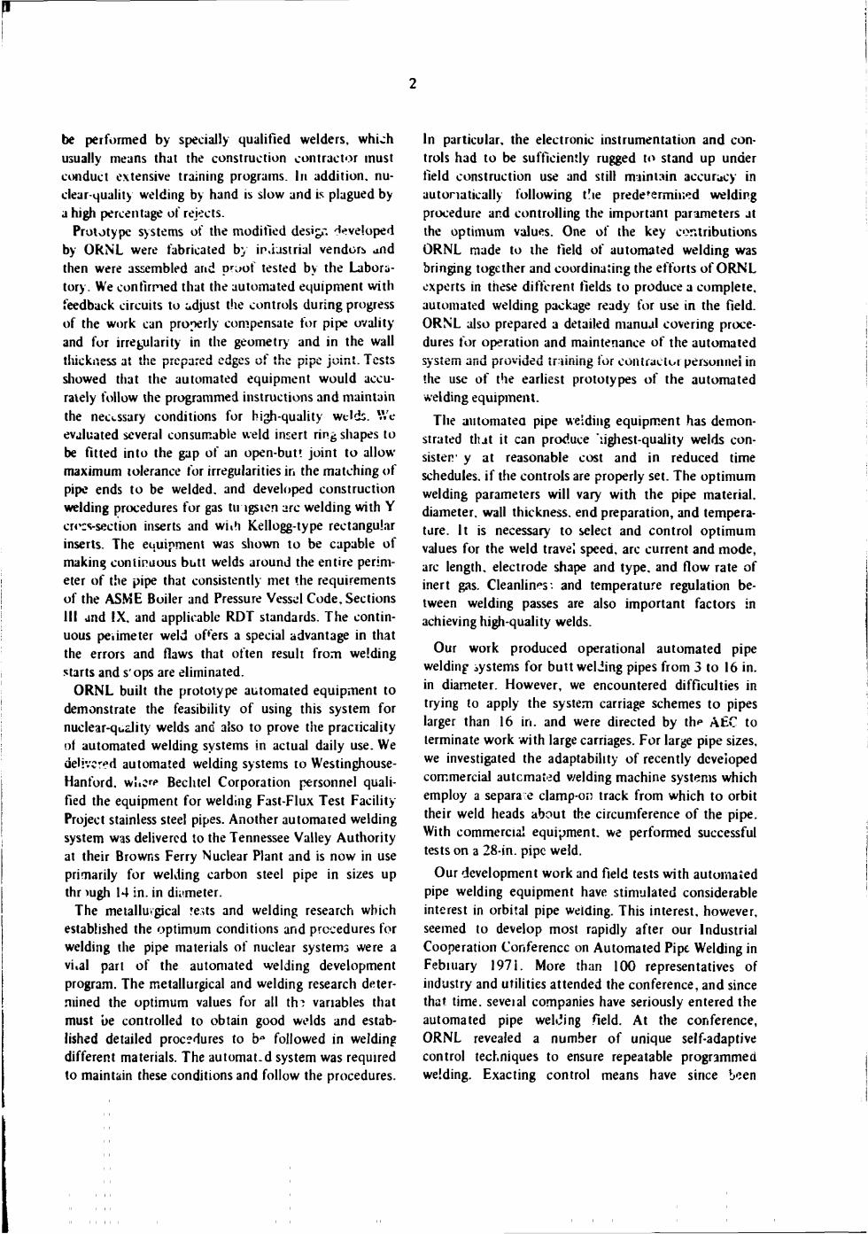
The ORNL automated weiding system consists of a conventional welding power supply, an electronic control consc'? called the programmer-controller, and an orbiting carriage that propels interchangeable welding or cutting heads around the circumference of the pipe. All equipment is ligh'weight, poitable, and compact and can be set up for pipe welding in a few minutes. At present, there are different orbiting carriages for the following ranges of pipe (outside) diameters: 3 to 6, 6 to 9, 9 to 12, and 12 to 16 in. (ref. 2). In these carriages, starting with the 6- fo 9-sn. carriage, the subassemblies and parts are interchangeable, as are the welding heads; this helps tc minimize the spare parts inventory. Figure 1 illustrates a typical automated
2. Operational models arc available for all size ranges except the 9 to 12 in.
present the highlights and results of the work. The report discusses the functional and mechanical aspects of the ORNL orbital machinery, the electrical and control systems, the study of weld joint preparation and optimum geometry, the techniques of the welding system, and the operator training requirements. The section on the electrical jnd vortrol system is relatively detailed, since, in principle, the operation of any automated welding system requires the same general approach to sensing, signal feedback, and automated response. The description of our control system, therefore, is generally applicable to commercial equipment as well, although specific control means may vary among manufacturers. The report also gives limited information on the commercial automated orbital welding systems manufactured in the United States as of July 1972.
Appended to the report are derailed sections to cover all specific controls and functions of the ORNL welding programmer-controller and a recommended format for establishing a welding procedure.
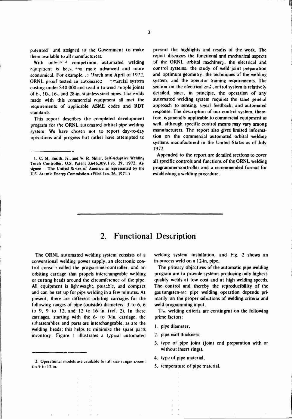
welding system installation, and Fig. 2 shows an in-process weld on a 12-in. pipe.
The primary objectives of the automatic pipe welding program are to provide systems producing only highest-quality welds at low cost and at high welding speeds. The control and thereby the reproducibility of the gas tungsten-arc pipe welding operation depends primarily on the proper selections of welding criteria and weld programming input.
Thv welding criteria are contingent on the following prime factors:
1. pipe diameter,
2. pipe wall thickness,
3. type of pipe joint (joint end preparation with or without insert rings),
4. type of pipe material,
5. temperature of pipe material.
2. Functional Description
4
PHOTO Y106815
Fig. I . ORNL aui'omated welding system installation prior to carriage placement on 12- to 16-in. pipe.
t
PHOTO 98593
Fig. 2. ORNL welding system in-process 12-in. pipe weld
J
6
The following welding parameters must be predetermined and programmed into the automated controls:
1. travel speed, 2. weld current, 3. arc length (arc voltage control), 4. Jiaiiiever and shape of tungsten electrode, 5. type and quantity of inert gas, 6. weld up and down slope, 7. wela start overlap, and weld tail-off distance, 8. weld filler wire and rate of deposit, 9. puis: current and puke sequence mode (if used),
10. oscillation- amplitude and frequency (if'.ised)T
11. iaterpass cleanliness and temperature regulation.
The input to the weld programmer provides for proper "in process" control and sequencing of all the
CARRIAGE
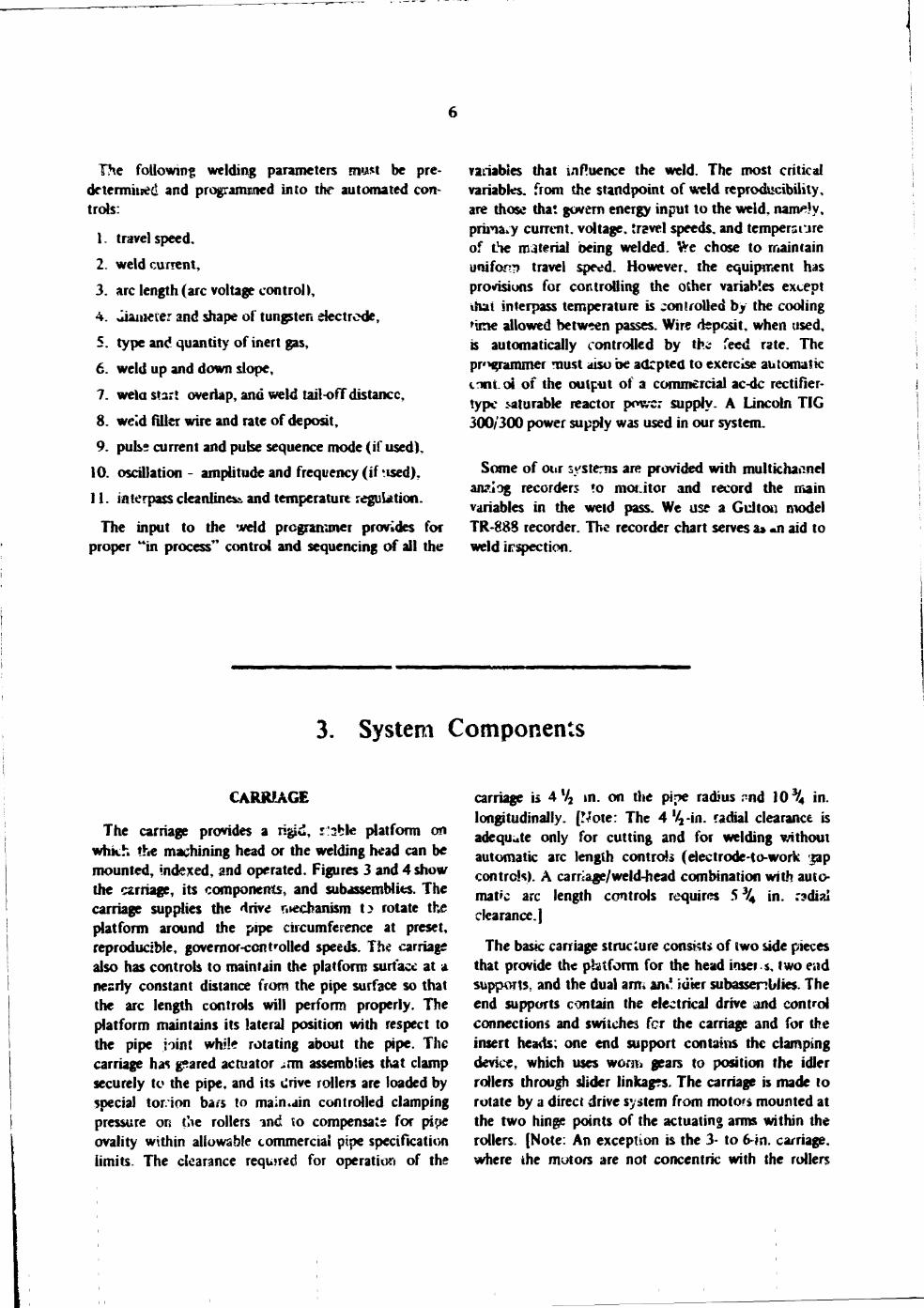
The carriage provides a rigid, r'sble platform on which the machining head or the welding head can be mounted, indexed, and operated. Figures 3 and 4 show the carriage, its components, and subassemblies. The carriage supplies the drive mechanism t> rotate the platform around the pipe circumference at preset, reproducible, governor-controlled speeds. The carriage also has controls to maintain the platform surface at a nearly constant distance from the pipe surface so that the arc length controls will perform properly. The platform maintains its lateral position with respect to the pipe joint while rotating about the pipe. The carriage has pared actuator -on assemblies that clamp securely to the pipe, and its drive rollers are loaded by special tor ion ba/s to maintain controlled clamping pressure on the rollers in& to compensate for pipe ovality within allowable commercial pipe specification limits. The clearance required for operation of the
variables that influence the weld. The most critical variables, from the standpoint of weld reproducibility, are those that govern energy input to the weld, nam*'y, prina^y current, voltage, travel speeds, and temperature of the material being welded, fre chose to maintain uniform travel speed. However, the equipment has provisions for controlling the other variables except thai interpass temperature is controlled by the cooling 'ime allowed between passes. Wire deposit, when used, is automatically controlled by the (eed rate. The pr' grammer must aiso be adrpted to exercise automatic inntoi of the output of a commercial ac-dc rectifier-type saturable reactor power supply. A Lincoln TIG 300/300 power supply was used in our system.
Some of our systems are provided with multichannel an?.iog recorders ?o monitor and record the main variables in the weld pass. We use a Gultou model TR-888 recorder. The recorder chart serves a» «n aid to weld irspection.
carriage is 4 V2 in. on the pipe radius -nd 10% in. longitudinally. [Wote: The 4 Va-in. radial clearance is adequate only for cutting and for welding without automatic arc length controls (electrode-to-work $ap controls). A carriage/weld-bead combination with automatic arc length controls requires 5 % in. r?dial clearance.)
The bask carriage structure consists of two side pieces that provide the pbtform for the head inser-s, two end supports, and the dual am, m* idkr subassemblies. The end supports contain the electrical drive and control connections and switches for the carriage and for the insert heads; one end support contains the clamping device, which uses worm gears to position the idler rollers through slider linkages. The carriage is made to rotate by a direct drive system from motors mounted at the two hinge points of the actuating arms within the rollers. (Note: An exception is the 3- to 6-in. carriage, where the motors are not concentric with the rollers
3. System Components
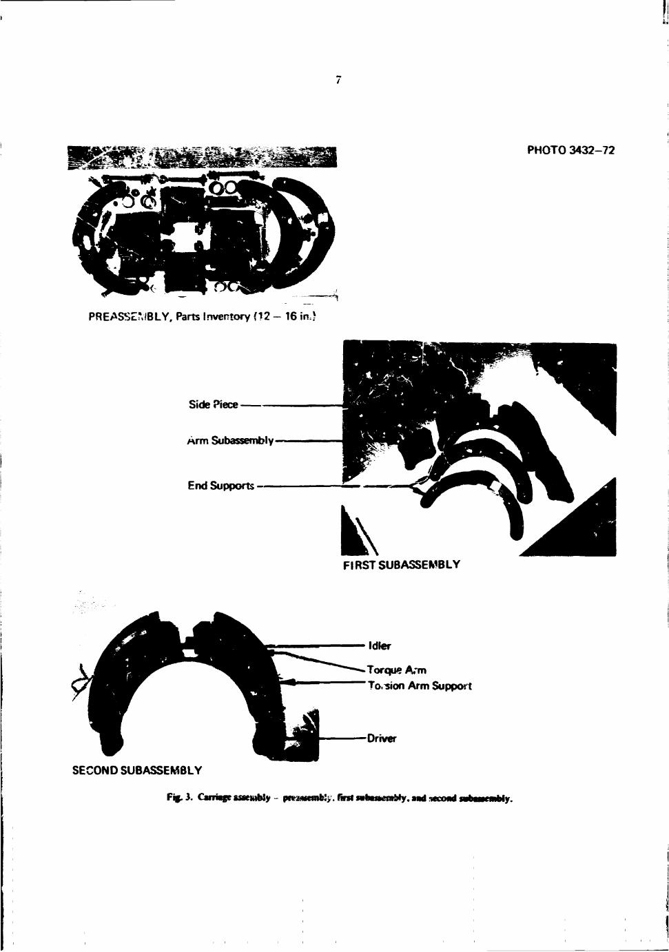
PHOTO 3432-72
PREASSEMBLY. Parts Inventory (12 - 16 irU
Side Piece -
Arm Subassembly-
End Supports —
FIRST SUBASSEMBLY
Idler
Torque Arm To. sion Arm Support
Driver
SECOND SUBASSEMBLY
Fig. 3. Carriage saeiubJy - prra*femb:>. first nbastemMy. and ttcond MDMmMy.
8
P-iOTO 3433-72
Travel Push Buttons
THIRP SUBASSEMBLY
Standoffs to Ride Pipe Collar for 2G Position Pipe Welding •
FINAL ASSEMBLY, Elevation View
.Stable Platform
•View Port
•Clamping Device Actuator
•—- T?.chmoi:or Drive
FINAL ASSEMBLY, Plan View
Fig. 4. Carriage msenMy - third! rubancinbly and final.
9
but are installed in canisters at th: hinge points of the f-?d automatically at a preset tied rate by means of a arms. Drive power is transmitted to the rollers through motorized wire feed mechanism. A standard 4-in.-diam.. identical gear trains in the an.*. The 3- to 6 in. direct 2 V2-lb wire spool is used to store enough wire for drive system is designed without torsion bars and multiple weld filler passes. The torch and the wire torque tubes and therefore offers less tool flexibility feeder are mounted on die vertical slide, and the wire duiing clamping and rotation. This simplified drive spool is mounted on the horizontal slide. The welding design cannot be used for larger pipe s zes. however. head includes inert-gas hose passages to the torch cup because 'he greater siic^aMe out-of-round tolerances plus power and cooling water lines to the torch head. A require more flexibility in the damping and drive motorized cam drive supported by the vertical slide mechanisms. J Vulcanized high-temperature, abrasion- oscillates the torch electrode across the weld seam. The resistant Viton rubber coatings on the roSers provide head ?5so contains integral switches for testing the traction for carriage propulsion. The carriage speed is operation of the wire feed jog (feed and retract), the adjustable at the programmer oscillator, and the inert-gas flow controls.
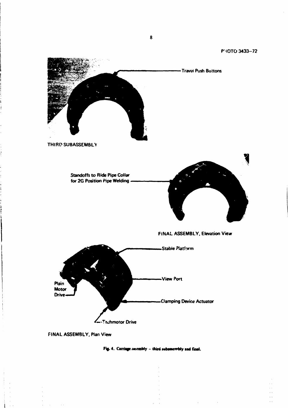
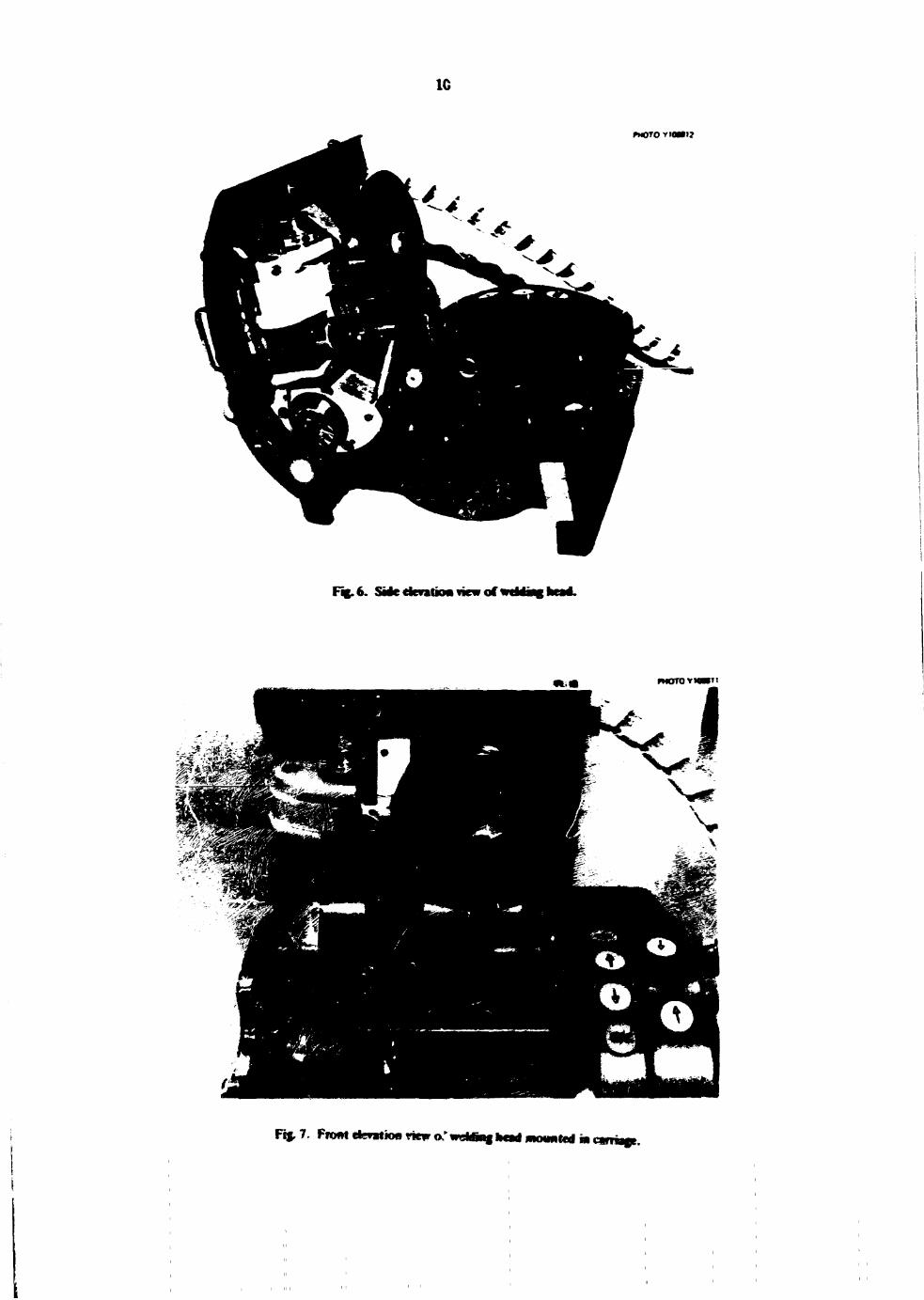
The welding head is shown in Figs. 5 r J 8. Figure 5 is a WELDING HEAD top view of die head with the lid in the closed (welding)
position, showing the power and control cabie entry to T he welding head has a motorized vertical slide and a the h*ad. am* Fig. 6 is a side elevation view showing the
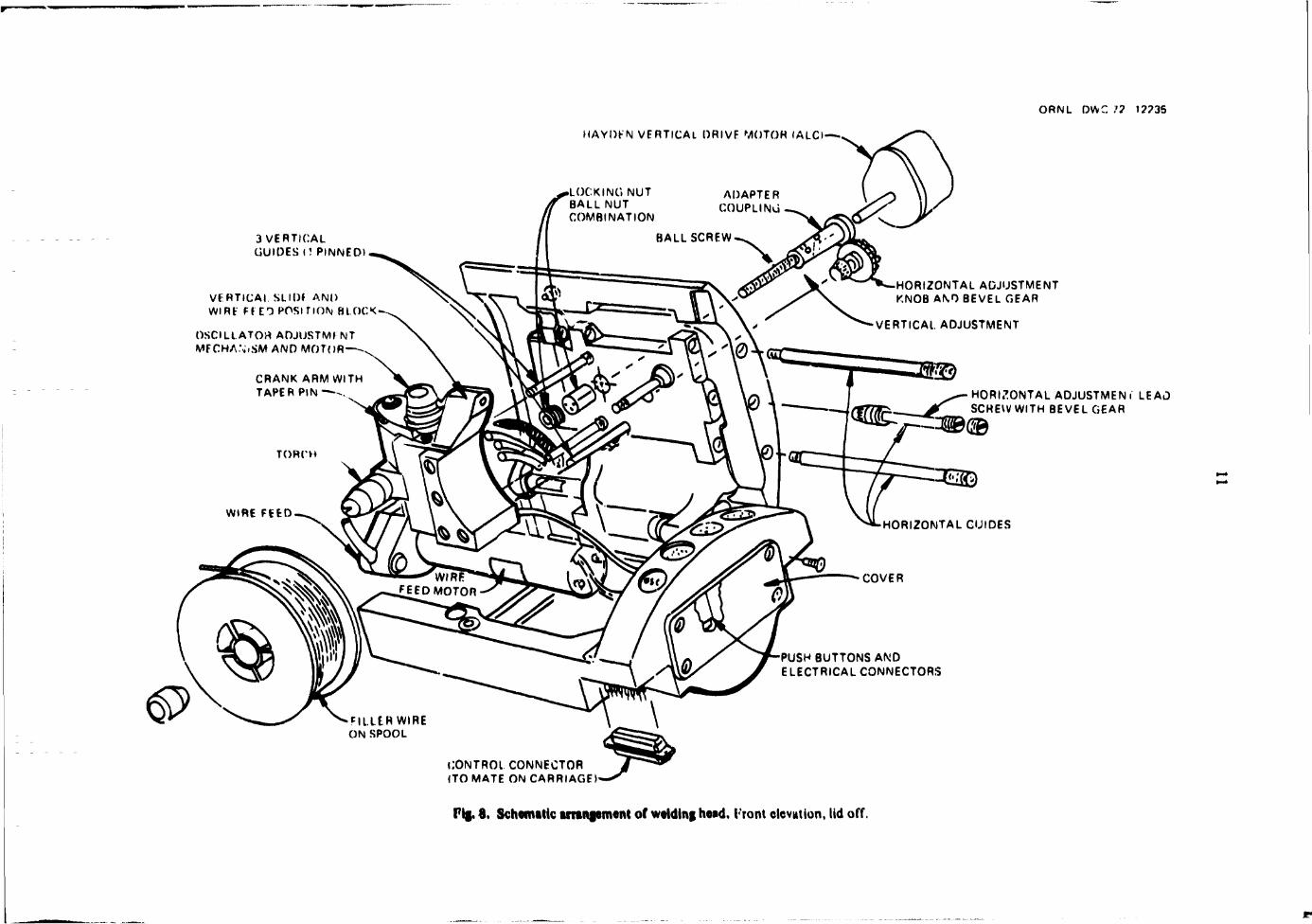
manually adjustable horizontal slide that can be set to hinged lid in the open position. A front elevation view locate the torch electrode accurately with respect to the ±a& a schematic illustration with the lid open are shown cut and beveled edges of a weld joint. Filler wire can be in Figs. 7 and 8 respectively.
Fig. 5. Toy w«w of wddwg head with lid dowsd (wtMiwi jtmtiom).
1C
PHOTO VIOMI?
F«.6. SMedevatKMviewor
moTOvioHi;
Fif.7. fnmtkgn»Hmriewo:wdUmghtaimommHdm
ORNL DWC .'? t??35
HAYDKN VERTICAL DRIVE MOTOR I ALCI—•,
3 VERTICAL GUIDES l! PINNED)
VERTICAL SLIDJ AND WIRE Ff ED POSITION BLOCK
OSCILLATOH ADJUSTMENT MFCHA\.SM AND MOTOR-
CRANK ARM WITH TAPER PIN .
HORIZONTAL ADJUSTMENT KNOB AND BEVEL GEAR
VERTICAL ADJUSTMENT
HORIZONTAL ADJUSTMENT LEAD SCREW WITH BEVEL GEAR
WBtiH
HORIZONTAL GUIDES
PUSHBUTTONS AND ELECTRICAL CONNECTORS
•FlLLtRWIRE ON SPOOL
CONTROL CONNECTOR (TO MATE ON CARRIAGE)
Fig. 8. Schematic arrangement of welding head. I'ront elevation, lid off.
12
Horizontal and Vertical Slide Assemblies
Horizontal torch position is adjusted by the horizontal Slide, which is actuated through a bevel gear linkage from a manual positioning knob on the lid top. The horizontal slide supports all the internal mechanisms of the weld head as well as the filler wire spool. Two horizontal guide shafts anchored to the weld head lid maintain the slide in alignment with the head. Three vertical guide rods and a (vertical) ball-screw drive couple the vertical slide block and the horizontal slide at right angles. An arc-voltage-controlled Hay den drive motor (ALC motor) is used to drive the vertical slide for maintaining the predetermined torch electrode distance from the weld joint. [Components attached to the vertical slide assembly are covered in subsequent sections.] It is important to note 'hat the entire vertical Mock assembly is integral with the horizontal slide and that, therefore, ail torch components move in unison. The relationship of the horizontal to the vertical slide is constant in the horizontal plane and varies only in the vertical plane when actuated by the ALC motor.
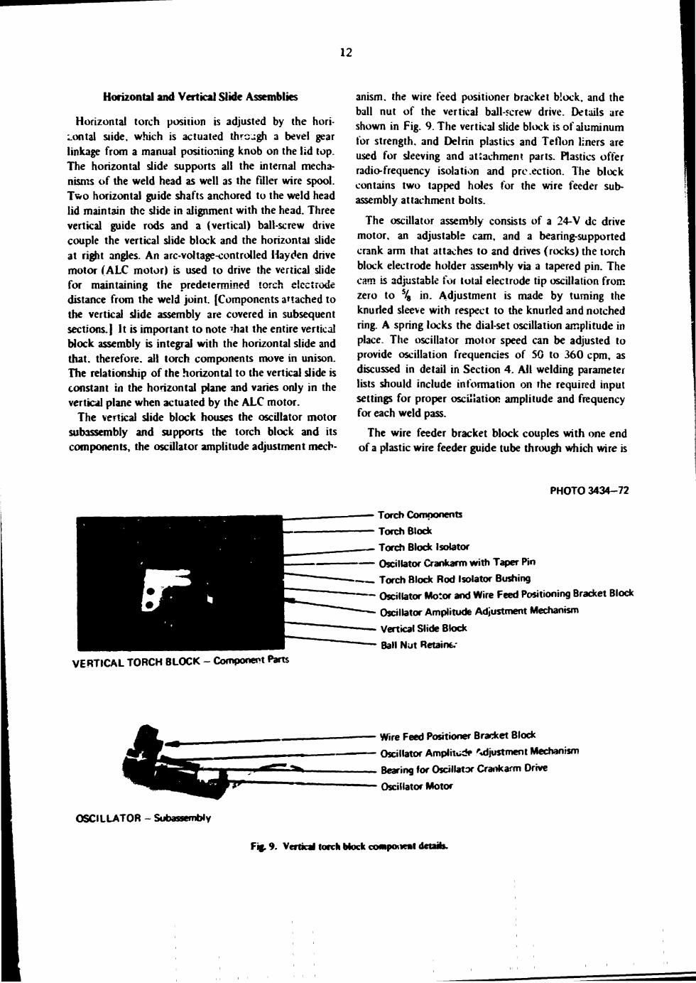
The vertical slide block houses the oscillator motor subassembly and supports the torch block and its components, the oscillator amplitude adjustment mech
anism, the wire feed positioner bracket block, and the ball nut of the vertical ball-screw drive. Details are shown in Fig. 9. The vertical slide block is of aluminum for strength, and Delrin plastics and Teflon liners are used for sleeving and attachment parts. Plastics offer radio-frequency isolation and pre.ection. The block contains two tapped holes for the wire feeder subassembly attachment bolts.
The oscillator assembly consists of a 24-V dc drive motor, an adjustable cam, and a bearing-supported crank arm that attaches to and drives (rocks) the torch block electrode holder assembly via a tapered pin. The cam is adjustable for total electrode tip oscillation from zero to % in. Adjustment is made by turning the knurled sleeve with respect to the knurled and notched ring. A spring locks the dial-set oscillation amplitude in place. The oscillator motor speed can be adjusted to provide oscillation frequencies of 50 to 360 cpm, as discussed in detail in Section 4. All welding parameter lists should include information on the required input settings for proper oscillation amplitude and frequency for each weld pass.
The wire feeder bracket block couples with one end of a plastic wire feeder guide tube through which wire is
PHOTO 3434-72
Torch Components Torch Block Torch Block Isolator Oscillator Crankarm with Taper Pin Torch Block Rod Isolator Bushing Oscillator Motor and Wire Feed Positioning Bracket Block Oscillator Amplitude Adjustment Mechanism
Vertical Slide Block Ball Nut Retain*.'
VERTICAL TORCH BLOCK - Component Parts
Wire Feed Positioner Bracket Block
Oscillator Amplitude Adjustment Mechanism
Bearing for Oscillator Crankarm Drive
Oscillator Motor
OSCILLATOR - Subassembly
Fig. 9. Vertical torch block component details.
13
introduced to the feeder mechanism. Threaded ferrules are used to anchor the ends of t.'.e guide tube.
A ball nut anchored and nearly centered within the vertical block allows the ball-screw drive to raise and lower the block. The screw directly couples to the motor shaft to raise and !ower the ba'l nut. Three guide rods, parallel and adjacent to the ball screw, serve to align and guide the movement of the vertical biock.
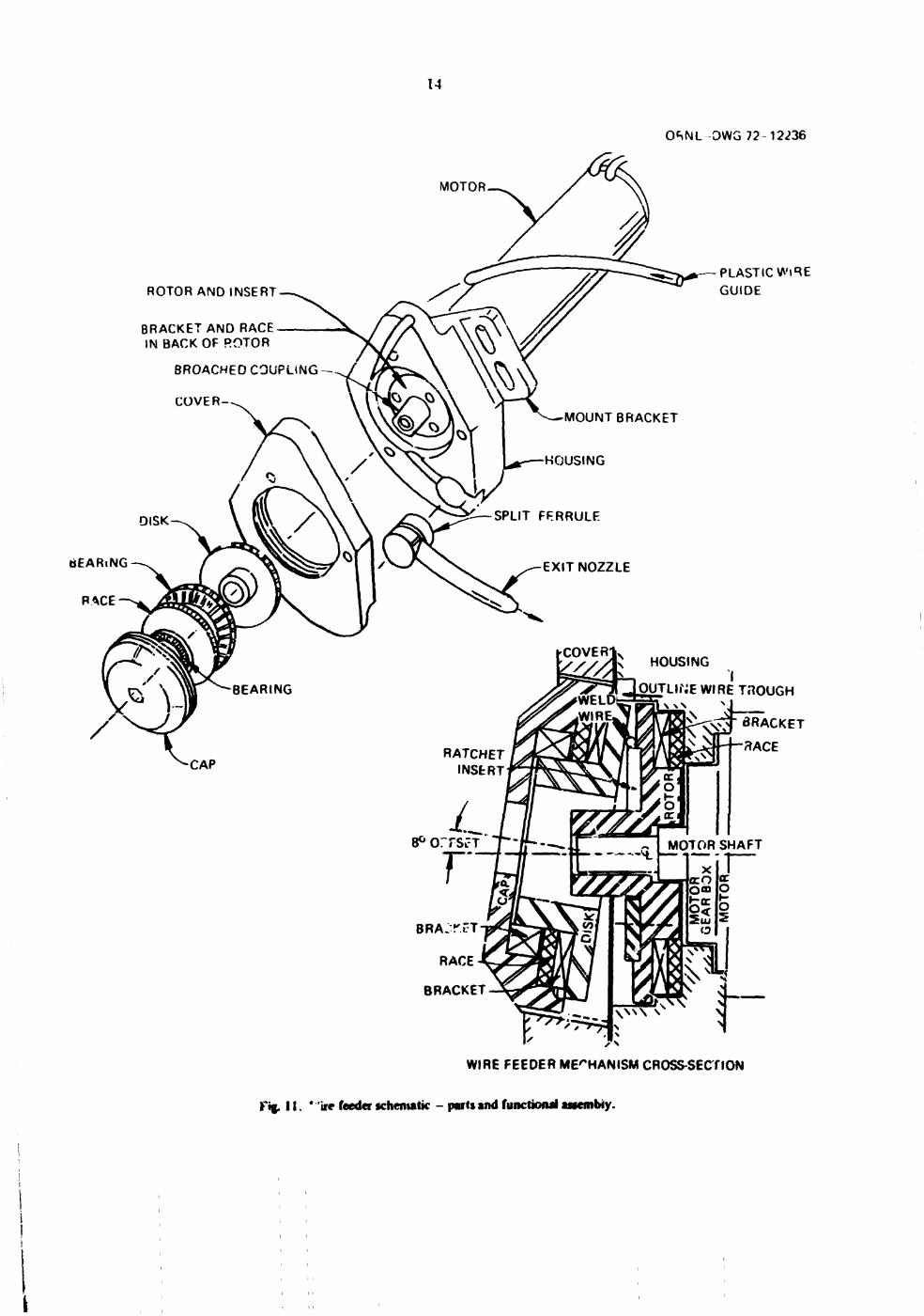
Wire Feed Mechanism
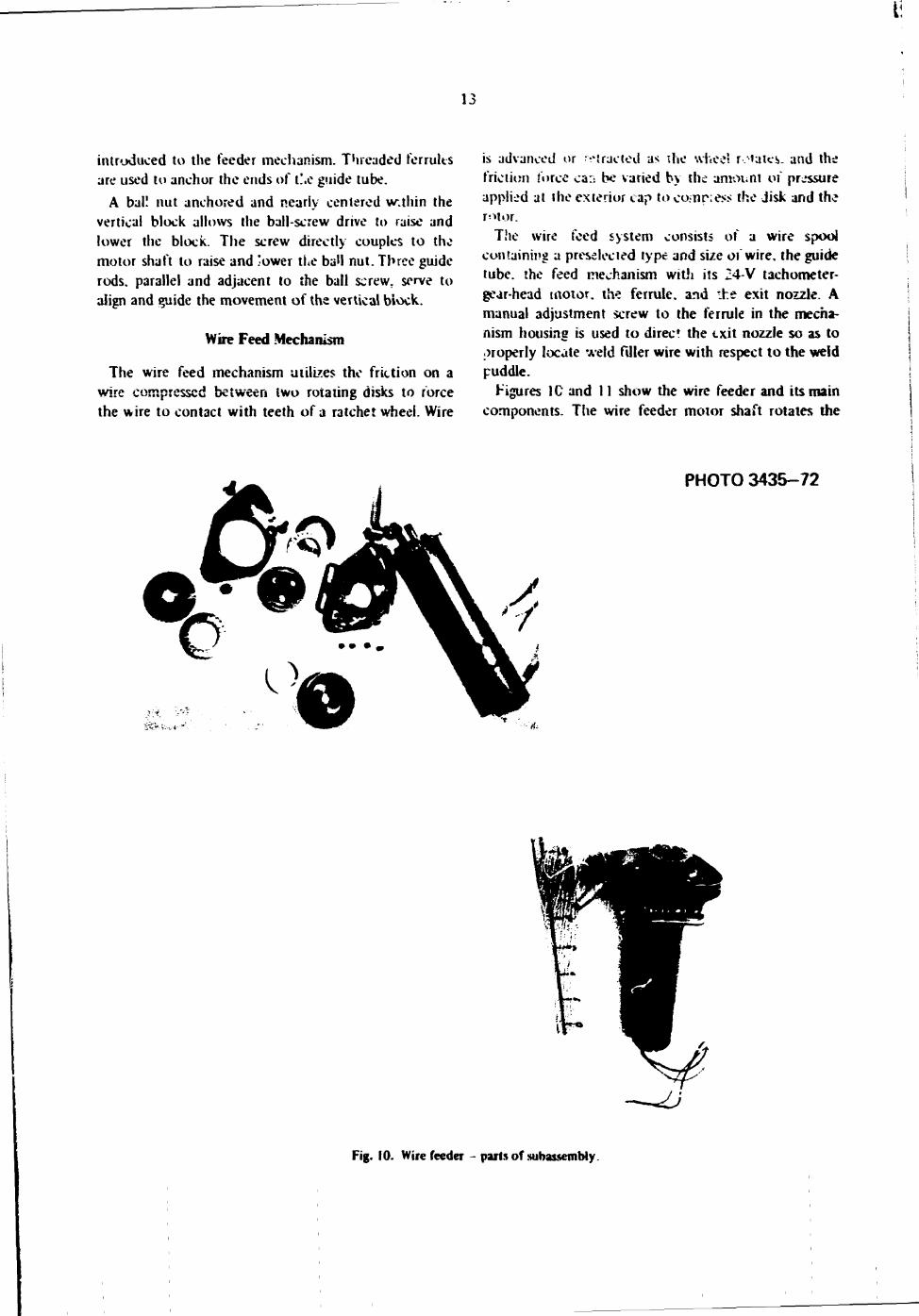
The wire feed mechanism utilizes the friction on a wire compressed between iwo rotating disks to force the wire to contact with teeth of a ratchet wheel. Wire
is advanced or t raded as ihe wheel rotates, and the friction force car: be varied by the amount of pressure applied at the exterior cap to co?nr;es> the disk and the r^tor.
The wire feed system consists of a wire spool containing a preselected type and size 01 wire, the guide tube, the feed mechanism with its 24-V tachometer-gear-head motor, the ferrule, and the exit nozzle. A manual adjustment screw to the ferrule in the mechanism housing is used to direct the exit nozzle so as to properly locate weld filler wire with respect to the weld puddle.
Figures 1G and 11 show the wire feeder and its main components. The wire feeder motor shaft rotates the
PHOTO 3435-72
Fig. 10. Wire feeder - parts of subassembly.
14
0«^NL OWG 72-12236
MOTOR.
ROTOR AND INSERT
BRACKET AND RACE IN BACK OF ROTOR
BROACHED COUPLING
COVER-
PLASTIC WiRE GUIDE
OUTLINE WIRE THOUGH
BRACKET
3ACE
WIRE FEEDER MECHANISM CROSS-SECTION
f'%. 11. * ire feeder schematic - parts and functional assembly.
15
rotor-ratchet insert combination. The cap and disk force the wire against the ratchet teeth until sufficient pressure is applied on the wire to pull it from the spool and feed it through the guide tube into the weld puddle. Thrust bearings are provided for both the disk and the rotor. The wire is prevented from moving toward ihe centei of the r o t c disk by a shoulder, and movement of the wire toward the periphery of the disks is prevented by the outer disk face being canted at 8° to the rotor disk face. The mechanism is designed to accommodate wire diameters from V, 2 to V I 6 in. and feed rates up to 50 in./min.
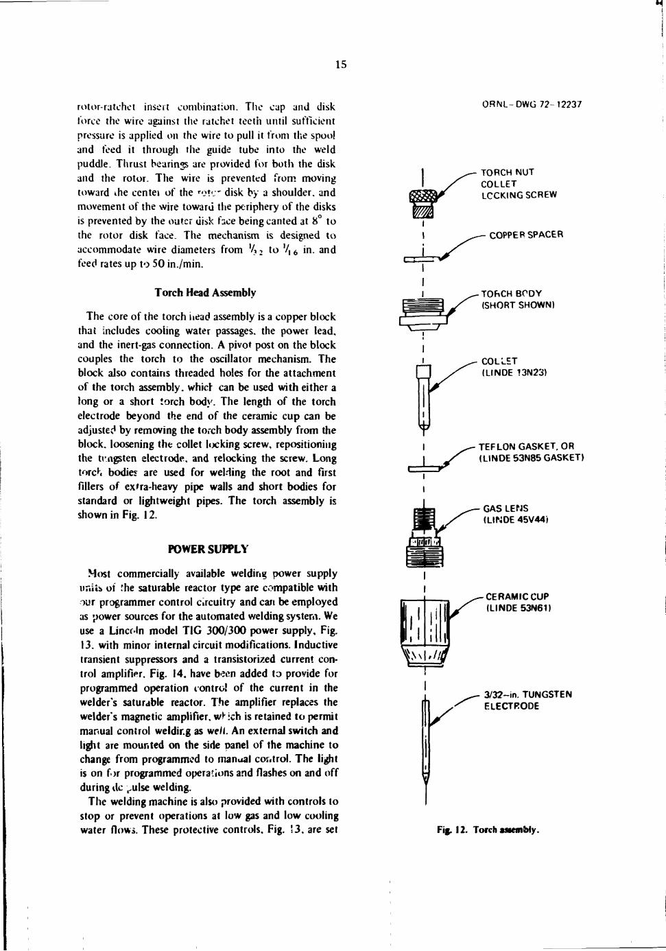
Torch Head Assembly
The core of the torch head assembly is a copper block thai includes cooling water passages, the power lead, and the inert-gas connection. A pivot post on the block couples the torch to the oscillator mechanism. The block also contains threaded holes for the attachment of the torch assembly, which can be used with either a long or a short torch bod}'. The length of the torch electrode beyond the end of the ceramic cup can be adjusted by removing the torch body assembly from the block. loosening the collet locking screw, repositioning the tungsten electrode, and relocking the screw. Long torch bodies are used for welding the root and first fillers of extra-heavy pipe walls and short bodies for standard or lightweight pipes. The torch assembly is shown in Fig. 12.
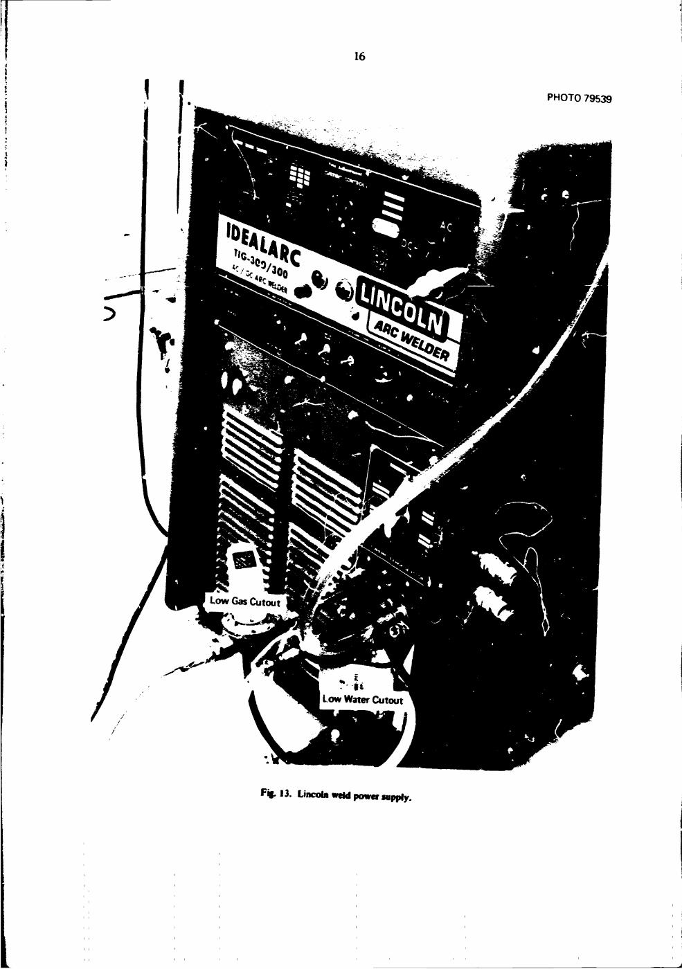
POWER SUPPLY
Most commercially available welding power supply nails of 'he saturable reactor type are compatible with our programmer control Circuitry and can be employed as power sources for the automated welding system. We use a Lincoln model TIG 300/300 power supply. Fig. 13. with minor internal circuit modifications. Inductive transient suppressors and a transistorized current control amplifier. Fig. 14. have been added to provide for programmed operation control of the current in the welder's saturable reactor. The amplifier replaces the welder's magnetic amplifier, wheh is retained to permit manual control welding as we/I. An external switch and light are mounted on the side panel of the machine to change from programmed to manual cor.trol. The light is on for programmed operations and flashes on and off during ilc ^ulse welding.
The welding machine is also provided with controls to stop or prevent operations at low gas and low cooling water flows. These protective controls. Fig. !3, are set
0RNL-DWG 72-12237
TORCH NUT COLLET LOCKING SCREW
COPPER SPACER
TORCH BODY (SHORT SHOWN)
COLLET (LINDE 13N23)
TEFLON GASKET. OR (LINDE 53N85 GASKET)
£r GAS LENS (LINDE 45V44)
V CERAMIC CUP (LINDE 53N61)
l.\\|»/fl
/
3/32-in. TUNGSTEN ELECTRODE
T Fig. 12. Torch assembly.
16
PHOTO 79539
F * 13. Lincoln weld power supply.
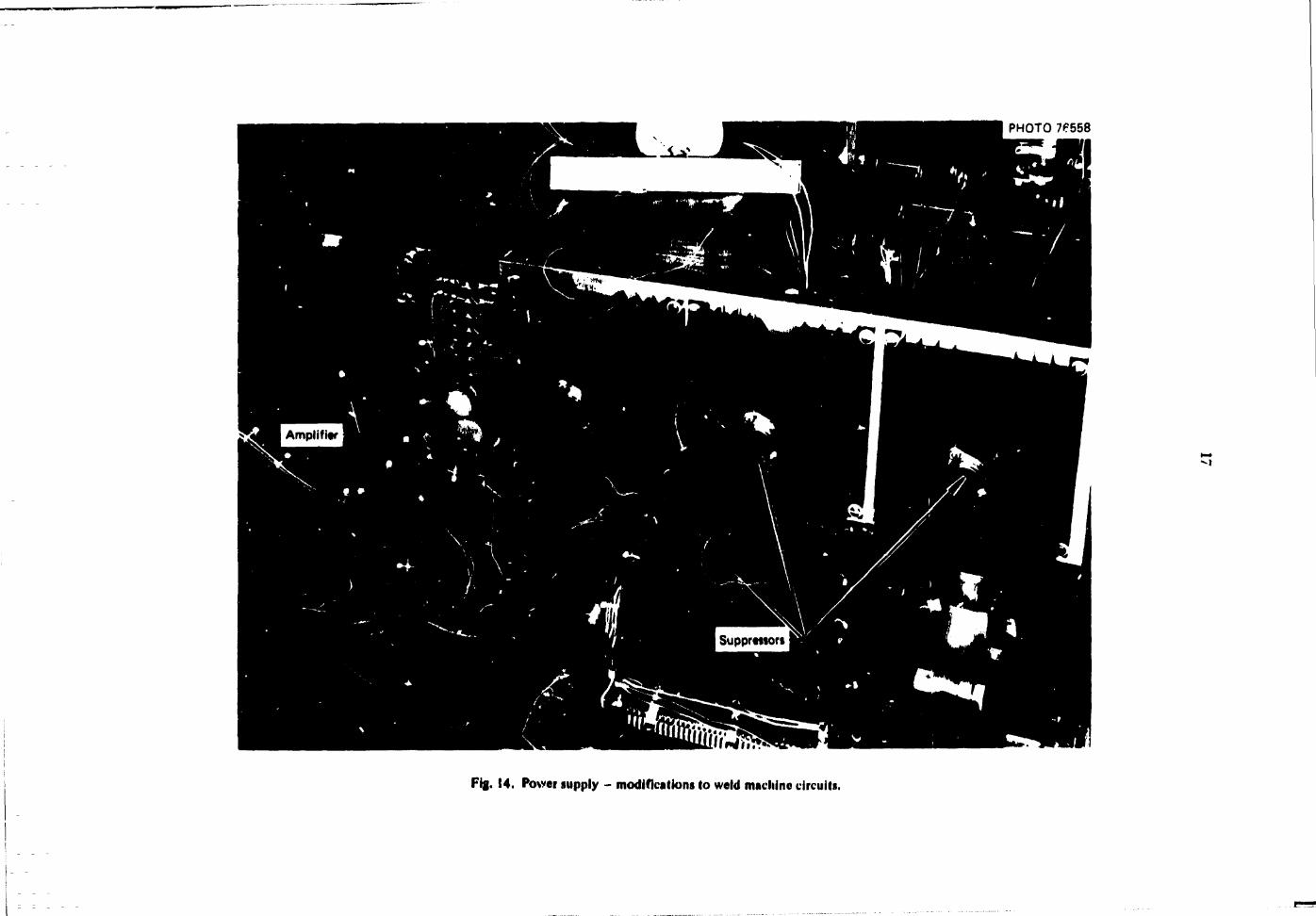
PHOTO 76558
M
Fig. 14. Power supply - modifications to weld machine circuits.
18
to downslope welding operations when the Hows of gas or of cooling water fall jelow the minimum levels. The controls are normally set fo. 12 ft 3 of gas per hour and V3 gpm of water, but can be set at other values if desired. These protectors will also prevent programmed weld startup if flow values are tess than the preset iates. A pilot lamp for each control lights up to signify insufficient flows. The gas an J water solenoid control relays, built into the welding machines as standard equipment, are by sseo for programmed welding operations. Signa1 an control wiring is transferred to replacement relays within the programmer.
Conventional H-2QA (AIRCO) water-cooled power and gas torch leads are used to connect the welding power supply and the torch in the weld head. A ground cable is employed to connect the work (pip?) and the welding machine's grounding lug.
PENDANT. SENSOR. AND CABLES
The pendant Jiown in Fig. 15 is a lightweight, portable, remote-operation station designed to be held in the weld operator * hand, in programmed weliing. the pei.dant permits the operator to observe a weld from a location close to the weld joint. The pendant provides weld start, downslope, and instant stop control and incluaes a set of push buttons to raise or lower the torch for preweld torch travel limit checks and for torch positioning. The buttons u;so serve to reposition or adjust the torch-to-work spacing during a weld, and the pendant o rheostat dial is available to regulate current in the manually controlled nv de of weld operation.
All pendant controls are housed within an anodized aluminum box structure. Electrical leads enter through
PHOTO 3436-72
Fig. 15. Remote-control pendant.
the handle, and a flex grip cable cover is used to avoid line crimping.
The equipment diagram in Fig. 16 shows all components of the welding system, along with the connecting cables and control ieadv
The current sensor shown in Fig 16 is a current transformer thyrector combination housed in an anodized aluminum box. The transformer features a toroidal coil encased in plastic, with a l-in.-diam center opening passage for the weld cable. The coil, in turn, connects to the programmer to supply a proportional feedback signal for precise current control.
Programmer Sines include a 120-V (5-A) at power supply, a signal control cable to the weld power supply, a current senior line, a remote-control pendant cabie. a signal cable to the recorder filter box and recorder, and the cont'ol cable to the weld head. The weld head control cable also includes a filtered arc %oitage return signal and combination cable shield and ground Hnes back to the programmer.
The weld power source includes a 460-V (60-A) ac supply as well as water and gas supplies. Output lines include waie.-cooled power lines and gas lines to the weld head torch. The welding machine must be grounded by building equipment ground. A ground cable, which passes through the current control sensor, also connects the machine's alternate terminal to the work.
RECORDER
An analog recorder can be employed to provide direct writing trace charting for the programmed welding variables. The programmer includes a rear apron connector for transmitting voo! speed, wire feed rate, and arc voltage data. A shunt at one of the weld power
source outlet terminals is used to provide a proportional signal level current input to the recorder. Leads from the connectors are routed through z noise filter box en route to the recorder. The multichannel recorder presently in use, Techni-Rite Electronics model TR-#88. modified to automatically start and stop with the weld sequence, is shown in Fig. 17.
A highly vief\>\ record of amplitude and uniformity of the variable? is obtained by plotting the weld functions. Deviations from the usual charted patterns indicate irregularities and often offer clues to the source of welding problems. Any plotted irregularities can also be interpolated to precise pipe location fo. immediate remedial action subject to the weld inspector's confirmation.

460 V (60 A) ac Supply I
I
!
Q
o JD
z O
o
61
20
© o > O K O X a.
e e
21
The TP.*#8 ccorder has eigh« ch-inneK In weto Je\ei *ment *=VK it is ofjen helpful to char; addi*?"nal »UJK «ons »« to hmi functions reb;r,o ;o one another
In rn*7nal onerat ««n. however, n is essvHigh to record the weld <|^vd. wire fecit rate, arc voltage, and arc current.
4. Electrical and Control System
PROGRAMMER-CONTROLLER
The function of the programmer is to pr-yvide automatic control M( rhe variables flat 3ffect weld quality. On the base t»f parameters manually preset into :.r=e programmer by means of dials and switches, the programmer-controller responds to data automatically fed back front sensors which monitor the actual weld>ng condit!ons. The settings of the dials and switches, together with haHware circuitry, comprise a programmed memory that comics the weld parameters in a predetermined m?nner. rate, and sequence. The feedback information is compared with the preset values in the programmer memory, and. if one of the controlled parameters v?nes from the desired operating range, correct.*e ac'lon is automatically initiated by the control system.
The variables confr.died are: 11) carriage (tooll speed: |2» arc length, the distance (gap) between the electrode and the weld puddle: I3» wire feed rate: ( 4 | welding current: (5) frequency of torch oscillation: and 161 gas and water flovk to torch.
Control parameters are preset in the pr»*grammer by me;«ns of dials and switches located on the front panel. tin: rear apron, and the pendant. Appendix A contains .ilu-vtraiions and tabular listings o\ the controls and fluMr (unctions.
All ihe contrived variables except the torch oscillation are monitored by sensors that feed back signals to the piogrammer.
The carnage (tool! speed and the wire feed rate are monitored by tachometers which produce dc feedback signals having amplitudes proportional to drive motor speed and polarities corresponding to the direction of motor rotation.
The welding '.-nnent is monitored by a current sensor which, together with its associated circuitry, produces a
unipoianty dc feedback signal proportional to the current.
The jrc voltage is monitored directly and fed hack to the com rob of the torch position (ALC). win? feed lAVCl. and stub-oui pa-anieters. ; "Stub-out" occurs when the torch touches the weld puddle.) This arc signal also opiates a voltage relay on which contacts are used as protective interlocks in the control circuitry.
The gas and water flows to the torch are monitored by How switches. Ctmtacts on these switches provide interlocks which protect the welding equipment and minimize damage to the weld and to the welded component by preventing startup and or initiating shutdown in the event of loss of watt-r or gas flow.
BASK SUBDIVISIONS OF PROGRAMMER CIRCUITRY
For purposes of discussion the programmer circuitry-may be considered to be composed of nine basic subdivisions, as follows:
I. welding current control circuits.
2 carriage < tool speed) control circuits.
3. wire feed I rate) control circuits (AVC).
4. arc length cont 'd circuits (ALC).
5. torch osciiiation control circuits.
6. gas and water flow circuit.
7. program control circuits.
8. stub-out circuits.
9. power supplies.
The program control circuits may be further subdivided into sequence control and sequence timing circuits.
22
The first six of the above cicutt wbdivtsions are functional^ in<kpender.t and may. under cettain wA#nU»-;;*»KS. 5k- .ipcr^fJ ^nd tested sepsrsteK If.^-ever during programmed welding operations the*; circus is respond to the demands oi the program control .rrrcuits and aie Iurrctitanally interrciated.
CONTROL ?.SOD£S
There are two major modes of programmer operation setectaole by panel switch. Manua' snd Program.
MamnlMode
!n this mode the carnage an*i wire feed may be operated manually with pushbutton switches i«Xdt<:4 on the carriage at speed d*tennincd by the setting of dials on the programmer panel: the weld curretH .*« be manually conir»j*'?»5 Ucn< the pendant' the torch can repositioned by manually oxr*:£<! push-button switches on &* pendant: and water flow, gas flow, and torch osc.'ation can be *ested by operating push-buttor switches on the weid hear' This mode of operation is u«d nmaZy for initial setup of the system for welding but is also useful for calibration, mainterunce. and troubleshooting.
Program Mode
In program mode the system performs five preset. tcner-controDe'l. sequential operations: prcpurge. up-stopc, weld, downslope. and postpurge. These operations are automatically controlled by a stepper relay and associated relays, switches, and power buses.
Sequence control. The stepper relay has 51 active positions and a home position. Positions I to 5 are used for prepurge, 6 to 10 for upslope. 11 to 30 for weld, 31 to 39 for downslope. and 40 to 51 for postpurge. Programmed operations are terminated in the 52d (home) position.
There are 8 banks of contacts on the stepper relay. Banks 1 and 2 determine the txisitions at which the prepurge. upslope. weld, and downslope and ,*>stpurge operations occur. Stepper banks 3 and 4 determine the position at which the carriage starts and it which the wire feed starts and stops. Stepper banks 5 and 6, together with a Vernistat mounted on the front panel, provide a means of setting the desired current profile in 34 discrete steps during the upslope. weld, and down-slope operations. The Vernistat is composed of 34 sliders which are sequentially selected as the stepper advances through positions 6 to 39 respectively. Each slider is a potentiometer voltage divider that feeds a
reference voltage -penal. *ia a stepper contact. »« the input ot the current servo amplifiers- The refercve vo'tage represents 0 t*s l&fl of "maxirwm welding current." An additional digital dial is pumded on 'he front panel to set the maximum welding current to any value up to 200 A. Thus the maximum weld current dial sets the upper voltage limit impressed across the Verrustat vctuge divider. Stepper banks 5 and i> arc-used to operate lights to indicate the position of the stepper switch throughout the program. A series of lights ibove the Vernistat sliders indicates the progression of im'% steps during upslope. weld, and down-slo»*e oner siions.
A programmed weid operation can be extended in any "in-weld" position to permit extended time operations. A weid c3s be stooped at any rime by pushing an "Emergency"* stop button for immediate step action or s "Pownsiope** button that causes the relay to fast-*iep to the downslofx position *nd continue programmed shutdown operations from that point.
Secfuence fining. All the toning functions in the programmer are performed by a unijunction oscillator 3-a a telephone-type stepping relay combination. Stepping rates change throughout the total cycle as the stepper advances from one sequence to another. This is accomplishes by utilizing several of the stepper contact decks to change resistors in the unijunction oscillator RC timing circuit. In this manner, prepurge. upr iw. weld. dowraJupe. and postpurge can al! be timed at different step rates by the same piece of equipment.
CURRENT CONTROL
Welding current is controlled by a saturable reactor in the welding power supply which responds to a refeience signal supplied by the Vernistat or by the current control potentiome'er on the pendant. The position of a front panel "Current" switch determines which of these controls is effective. When the switch is in the "Manual" position, the reference signal is supplied by the pendant control, and when the switch is in the "Program" position, the signal is supplied by the Vernistat. The reference signa* is compared to a feedback signal which is directly proportional to the actual welding current. The difference in these signals is obtained by diode bridge circuit arrangement and input to the first stage of the current control seivo amplifier. The amplified difference obtained from the output of the servo amplifier is coupled through an isolator amplifier to a power amplifier. Here it is further amplified and applied to the input of a driver amplifier in the welder power supply which indirectly controls
23
the welding current b> controlling the current in the saturable reactor control winding. The net result of" this action ts to maintain the welding current ai a value which is very warh r>r:>portk>nal t«» the reference signal voltage s-pplied b> the Yerr.istat or the pendant control.
The feedback signal is supplied by a current sensor through *hkh the welding cable r asses. This sensor has two nuxjcs M opc^_»'un lac or Uci which are manually fdec table to correspond to the welding current selected. In th« dc mode the sersor functions as a saturabk-reac'or-type dc transformer in which -he control current is the welding current: in the ac mode it functions as z cure-it transformer. In both modes the output is an ac vintage which L> certified by a diode bridge and tHieied to obtain a smooth dc feedback voltage.
The programmer's servo isolator and the welder power and driver amplifiers obtain then supply voltage from the wdder power supply. This voltage is a rectified half wave (not a smooth dc). and iht ground system for these amptifko is common to that of the *t!der power supply. Tlie servo isolator amplifier which consists of '. optically coupled diode and associated circuit A . provides the necessary isolation between the welder and programmer grounding and voltage s) stems.
The welder driver amplifier is basically an emitter follower wiih a high current gain. It derives its signal frorM an external source and has a faster response, but otherwise performs the same function as the mag>;?tic amplifier supplied with the conventional power supply and retained in the modified Lincoln welder power supply. A current control switch, located on the side of the weider power supply, selects either the driver amplifier for remote < pn «gramrn.c;c> control or the magnetic amplifier for local control.
PULSE CURRENT
The welding current pulstr is incorporated in the system to aid in control of the molten puddle for pulsed and/or out-of-position welding. This unit modulates :hc voiding cuirent servo amplifier at either 40 or 60 cpm and is switch selectable from the front panel. Pulse amplitude is dialed directly by a potentiometer on the front panel that is calibrated 0 to 100 A peak to rwak.
The dial light on the maximum current potentiometer gwws alternately bright and dim at the pulse rate seL* ted. Pulsing is accomplished by modulating the voitx*e supplied by the maximum current potent iom-
etvr to the V'e.nistj: tor manual pendant c«*ntrol) w ;;h j "kjuare-wavc tolfage «:cr:,:'.jied b\ a relaxant*! oscillator The peak-to-pvas. amplitude potentiometer adjusts the amplitude of the m>Hlulak!'.«*i voltage.
TORCH OSCILLATOR
The vintage to the oscillator motor is varied by a Darlington iransisKH pair to prt*ide control of oscillator spvei. An illuminated potentiometer dial on the front panel calibrated 50 to 360 cpm furnishes the Sienal t o the Darlmrfon nair rkt-ilbfor arnnJMijHe ES
adjusted in the weM head by an eccentric cam mechanism. There h no feedback in the oscillator circuit. The oscillator is turned on and off by applying and removing supply voltage to the oscillator amplifier.
TOOL SPEED CONTROL
The tool drive motor is a dc servo motor driven by a servo amplifier through either the tool forward or tool reverse relay. The speed of the motor (and the carriage) is determined by the amplitude of the output voltage from the servo amplifier. The direction of rotation is determined by the polarity of the voltage across the motor which b in turn determined by the position of the tool reverse re!ay. The servo rrnphfier has two modes of operation, with and without feedback control. A "Tool Servo" selector switch on the back apron of th* programmer designates the mode of operation. When this switch is on. a dc voltage from a tachometer that is an integral part of the drive motor is fed back to the input of the servo-control amplifier, where it is compared with the dc signal voltage from the programmer. The difference in these voltages b amplified and fed to the motor. The net effect is to maintain the speed of the motor constant at a value determined by fh~ input signal voltage that is dialed into the tool speed potentiometer on the front panel of the programmer. Dialed values apply for forward travel selections: maximum potentiometer output speed or fast reverse will automatically occur with reverse tool travel demands. The effect of feedback L< to maintain motor speed at a desired value regardless of changes in load, line voltage, or amplifier gain. In this mode of operation the feedback signal from the tachometer is also fed to a meter on the programmer panel to indicate tool speed.
When the tool servo switch is in the off position the feedback circuit is disabled, and '.he tool iperd meter is switched to read the input signal instead of tachometer feedback.
24
WIRE FEED CONTROL AND AVC
When the programmer » in the Manual mode, or when the AVC wire switch on the programmer from pand is off. the operation of the wire feed servo system is similai to that of the tool drive servo _ .stem, except that the speed of the tool drive motor is fixed at maximum in the reverse direction.
When the programmer is in the Program mode and the AVC wire switch is on. 'he input sigral to the servo am- Itficr ! which dei'.iiisifics the wire teed rate) is a function of the arc voltage as well as of the setting of the wire speed potentiometer and the setting of an arc vote potentiometer on the programmer front panel. The response is determined by com?aring a set-point signal proportional to the ietting of the AVC volts potentiometer with the arc voltage between the electrode and the weld puddle. The difference in these voltages is amplified by the AVC wire module ?nd applied to the input of the wire feed control amplifier through contacts in the wire feed forward and reverse relays and the tool servo switch. The arc voltage signal is taken directly from the weld electrode and, after filtering to attenuate RF (radio-frequency) voltage, is passed through an interlock contact on the contactoi relay and fed to the input of the AVC wire module. The AVC circuits are adjusted so that the wire feed rate is one-half that set on the wire speed potentkjmeter when the arc voltage is equaJ to that set on the arc volt prtciiikxneter. An increase in arc voltage produces a proportional increase in the wire feed rate. Conversely, a decree* ;n the arc voltage produces a decrease in the wire feed rste. When the AVC wire switch is off. the output of the AVC wire module is clamped at +30 V dc and the wire feed rate is insensitive to variations in arc voltage.
The purpose of this cascade control arrangement is to r.gulate the wire feed rate in such a manner as to maintain the arc voltage as nearly constant as possible under conditions of varying spacing between the electrode and the weld resulting from pipe eccentricity, irregularities on the surface of previous passes, and flow of the wdd puddle toward or away from the electrode due to gravitational or other forces. For example, if. due to gravity forces, the weld puddle moves toward Ihe dectrode. the aic length and arc voltage decrease. In general, over the ranges of interest, the arc voltage is directly proportional to the arc length and is relatively insensitive to arc current. Ihe AVC system detects a
decrease in arc voltage and decreases the wire feed rate by the amount required to slow down the buildup of the we'd puddle to the point where the desired arc-length and voltage are restored. Conversely, if the weld puddle moves away from the dectrode. the situation is reversed, and the wire feed rate is increased until the desired arc voltage is restored.
The AVC system may be used independently or in conjunction with die arc length control (ALC). The design intent was that only the ALC control would be used in the root passes and that both systems would be operational during filler passes. In the latter cases the AVC system would provide the fine control and the ALC system woui-J provide a reset action to keep the AVC within its operating limits. The system is quite flexible, however, and the operator may find that under certain conditions he can obtain better wdds by setiing the AVC and ALC controls so that the sysum operates in a manner different from that anticipated by the designer. As is the case for most control systems, the proper control settings vary with the application and must be determined in the fidd.
ARC LENGTH CONTROL (ALC)
The ORNL programmer includes a systerr {ALC) inat monitors 'he arc voltage and automatically adjusts the arc length to a preset value within a prescribed range. Two front pand dials labeled "High" and "Low" are provided to set the arc voltage limits at which corrective torch motion will start. The center dial, marked "Average." is used to set the arc voltage at which corrective vertical (radial) torch motion will cease.
A printed circuit board in the programmer contains the circuitry and relays that control a motorized ball-screw drive in the weld head tr reposition the torch radially with respect to the pipe. The preset control range provides an area ii. which the automatic wire feed rate control can operate. In essence, the ALC system provides coarse con'rol and the wire feed rate system provides a vernier ontrol for maintaining the arc voltage at a precise value.
ALC also operates in conjunction with the pulsed current mode and causes the weld puddle to chill on a regulated bosis tc maintain a perfectly centered, uniform vtid bead, regardless of the position of the orbiting head on the pipe.
25
The input signal to the ALC system is the same (arc voltage) signal used as input to the AVC system. After passing through switches which correct for torch polarity and an adjustable gain buffer amplifier, the input signal is compared with the voltdges from the three (high, average, and low) limit set potentiometers, and the differences obtained are amplified and used to operate transistor switching circuits which, in turn, operate the up and down drive relays that control the torch position motor. When the up relay is energi/ed. the motor drives the torch away from the work: when the dov.Ti relay is energized, the motor drives the torch toward the work. The settings o( variable resistors connected between the supply v>ltage and the motor determine the motor speed in the up and down direction. Interlock contacts between the ALC circuit and the motor disable the ALC action when the contactor relay is deenergized; however, in the manual mode of programmer operation, the motor can be run in either direction to preset the gap between the tungsten electrode and the pipe surface by manually operating push-button switches on the pendant which bypass the contactor interlocks.
STUBBER CIRCUIT
The stubber circuit initiates a programmed shutdown in the event that the torch touches the weld puddle (called "stubbing"). The signal used to initiate this action via a plug-in foibber boar J module inside the programmer is the same that is used to operate the arc length control. The effect of stub control is to automatically initiate a downslope action as though the operator had anticipated stubbing and pushed the downslope button on the pendant. This prompt automatic action prevents electrode tungsten contact with the weld puddle, causing damage to the torch and contamination of the weld.
GAS AND WATER INTERLOCKS
Gas and waier interlocks protect the welding equipment and minimi/e damage to the weld and the welded components by preventing startap and or initiating shutdown in tire event o\ loss of gas or water How. If either gas or water flow is losi during the ^repurge programmed sentence, the timer will stop and the program w»ll halt at that point. However, if such flow is lost after the weld cycle starts, the programmer will fast-step to downslope and continue programmed operations from .liai point. Both flows are monitored by a separate flow switch connected in the gas and water lir.es. To obtain the required speed of response, switches having a low internal value in the downstream side were selected and mounted on the upstream end of the flexible cables to the welding head, at the gas and water outlet connections on the welder power supply-
POWER SUPPLIES AND POWER BUSES
The five power supplies in the programmer are as follows:
1. +28 V dc (nominal) uniegulated. 2. +30 V dc regulated. 3. ±15 V deregulated (ALC). 4. ± 15 V dc regulated (pulser). 5. +40 V dc (nominal) unregulated.
The first four of these are in the programmer and are energized when the power switch on the programmer front panel is on. The +40 V dc is supplied from the welder power supply when the welder contactor is closed, that is, during the welding cycle.
26
5. Welding Studies, Weld Joint Development, and Welding Schedule
Early efforts toward developing procedures for automated welding were often hampered by miner equipment or instrumentation malfunctions. Our early program goals were twofold: to improve system components for prolonged operation and. simuitaReocsly. to seek programmer-controller input settings that would yield acceptable welds that would be accurately repeated by the automated system. The weld joint was iimited to shape* usually employed in manual velding practices.
In the course o( our studies, we found that ihc tc h-to-work distance control is most critical .ind were able to maintain nearly constant torch-to-work spacing* by adding a motorized ball-screw drive on the ver<*cal sliCt to move the torch in response to a feedback signal from the arc voltage. For the ORSL system using gas tungsten-arc welding, optimum arc voltages range between 7 sn4 9 for stainless steel and carbon sted pipe materials. A variation i f 0.1 V in the arc voltage represents about S mils in the arc gap. The nominal arc gap of 0.1 in. is controlled within ±0.025 in. by the new system.
Many manual w«Hds are made with open butt pipe joints. The common joint configuration features a V,fin. root face and 37 '/2° bevel for each pipe end. and a V^n. r o o t P*V- The use o( consumable weld insc'i rings to fill this gap between adjacent pipe ends helped in establishing a root pass welding automat \-control program wh**1* voided consistent. high-qualtt> welds. The use of consumable inserts offers an additional advantage in that it is possible to select inseri nag metal compositions which will blend with many pipe material alloys and proviric metallurgical adjustments to pi ontoie c»ack-frcc w^Ms. The use of inserts also makes it easier to handle the problems of mismatching pipe ends and of irregularities in the root face and/or the pipe inside diarr te?. As the wold is formed, ring-face and cruss-seciion uniformity adjusts and eliminates puddling problems otherwise oused by geometrically poor joint matchup.
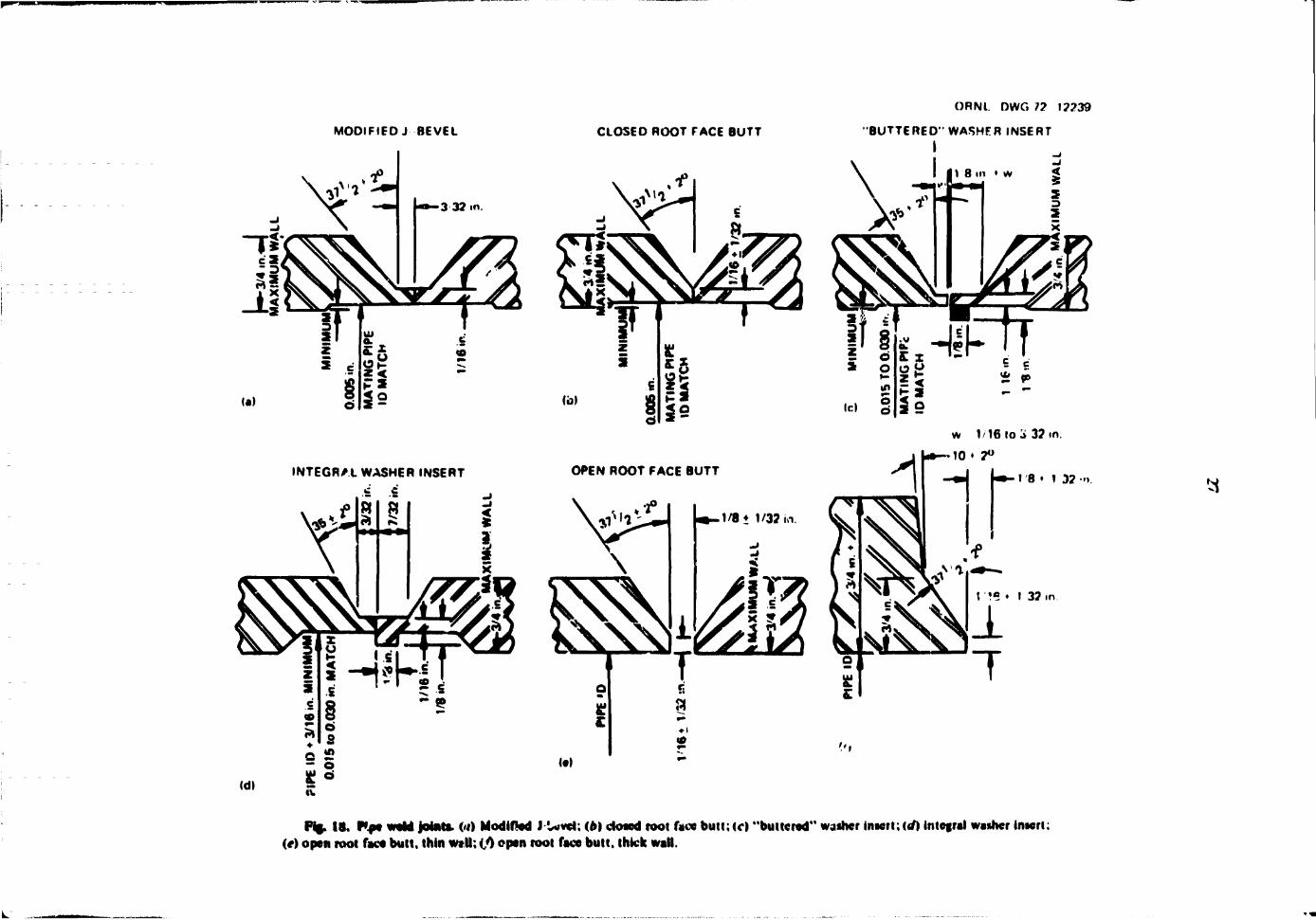
After several unsuccessful attempts to weld conventional V-groove ouit joints wc begati using modified J-bevel pipe end preparations (Fig. IKa). In V-groove butt-joint welding (F«g. !Hbh wc were unabic to attain uniform and complete penetration for the root pass, especially with pipe* in the 5(i (horizontalJ position. The modified J-beve/ pipe, end preparation was sebcted
for automated welding applications after we developed rhe remote cutting methods for providing such joint preparations.3
E?.rly gas tungsten-arc wlding with the automated orbital equipment on the modified J-bevd joints, however, required precise weld joint machining to obtain matching pipe inside surfaces and pipe wall thicknesses, as well ;*» near-perfect alignment of the two joint members and critical selections for the right amount of filler wire addition;. Failure to meet these requirements resulted in root welds either undercut and lacking full penetration or over-penetrated with a resultant heavy convex bead protruding inside the pipe. Fill pass welding is less difficult, although w« noted thai the quality of successive passes depends on prior weld passes. It is quiie simple to lay good fillers over good root passes or over f^^d prior filler passes, but it is difficult to repair a poor pass by welding over it without first machining out the defect. It has been our experience that special care must be taken to select proper heat control (weld current and weld speed) for the first, or for the first two. fill passes over an acceptable root pass. Too much weld heat will cause hum-through or drop-through, whereas insuffrient heat will result in lack of fusion or inadequate joint side wall tie-ins and weld cracking.
It is time consuming and difficult to do precision machining by remote control, ind pipe precision machiQing and slit/tment add greatly to construction costs. For these reasons, we next concentrated on experimentation with pipe joint configurations that permit plain fusion roof pass wc!Ui»>g either without or with minimum filler wire additions Later, we tried "buttered" washer insert joints (Fig. 18c) for our remote weld feasibility studies. A buttered insert is prepared by depositing wdd metal around a pipe inferior and then machining 'h<: deposit io a washer shape. It is possible to select welding (fill deposit) wires of tiie proper chemistry to adjust the base metal composition of the pipe for ct«ck-free welding and for pt >per fine grain structure interphasing with the base meial. Weld results were promising: ihe buttered joint
3 P. P. HoU. f-etsitUitv Study of Remote Cutting ami WHding for \uclecr Man Maintenance. ORNL-TK 2712 (November! 969).
ORNl. DWG 17 12239
MODIFIED J BEVEL CLOSED ROOT FACE BUTT
INTEGRAL WASHER INSERT
•BUTTERED" WASHER INSERT
! I |1 8 m • w <
ff ft ^(TtT * o
Id § 15 ii
* 9>
w 1/16 lo 'S 3? in.
10 • 7° OPEN ROOT FACE BUTT
t '•« • 1 32 m
32 •<>.
Fl8- 18. Rpe weld joint*. <<i) Modified J U v d ; (b) ctosed root face butt;(c) "buttered" waiher inaert;«f) integral wanner inaeri; (*) open root face butt, thin wt.ll; (,0 open root face butt, thick wall.
28
was definitely less dependent upon precision mating pipe joint geometries and alignment. However, since buttered joints are expensive to prepare, we resorted temporarily to integral washer inserts (Fig. I8d). that is. we simulated buttered insert shapes by machining heavy-wall-section pipe on the inside surface. Many tests were run to determine the best criteria for root width, root face, and (integral) insert dimensioning. From the results of tuts work, we then developed programmed input data for repetitive quality pipe wddments and formulated guidelines for welding with commercially available insert shape substitutes for the integral shaped inserts. All experimental work in studies to ad -M automated orbital wddffig equipment for high-quality construction pipe welding applications concentntej on pipe fo*r»ii that were suitable for welding with commercial consumable insert shapes.
Usual construction work pipe wilding practice specifies the open-butt V-groove weld joint. Th* joint shown in Fig. I8e for pipe wsu thicknesses of */,* to % in. generally calls for a root face of V,» ± %lyt in., a 3? '4 t 2° bevd. and a % *- %2 «»• root pp. Similar values had for w*H thicknesses greater than \ in., except the bevel angle decreases to !0 ± 2° starting at the %-in. wall depth, as shown in Fig. I8f.
With the shift in program goab to adapt the automated orbital equipment to nuclear construction work, concentrated efforts were made to attempt to maintain or adapt uV «rdd joint geometries commonly used in construction. Based on the aforementioned experience from ou' remote applications work, we concluded that open-but: pipe welding with ORNL equipment would at best be margiral. We therefore selected commercially available consumable inserts that would normally lit the cavity, or opening, between matching joints of an open-butt pipe joint to permit the contractor to make weld setups which could be wdded either manually or with automated equipment. Since many contractors purchase pie fabricated, or precut. rnd-prepped piping, the capability to utilize automation interchangeably with manual practice on the same precui erids is important, especially when introducing automation *.o the field construction job. We also realised that contractors who had manual welders qualified for hand welding with specific pipe end prtparatiras and consumable insert shapes could insist on qualifying automated welding for identical en& ind inserts in order to retain manual welding capability for times that the machines may be down or where .-cnsiruciion schedules compel maximum total productivity. Therefore we decided to establidi data for automated welding with both rectangular and Y-insert «hapcd consumable rings.
We first investigated welding with Grinncil rings (Grinndl Corporation. Providence. R.I.). The standard Grinned consumable insert for pipes 2 in. or more in oiameter has a cross section V,4 in. wide by V l 4 in. deep. Our experimentation indicated best result* with two Grinncil rings stacked together, or for a Vin.-wide. ^,*-in.-deep cross section. Root welds v.ith single rii.js were of uneven internal contour: SG position welds with proper contours in the 12 o'clock position exhibited suckback near the 6 o clock position.
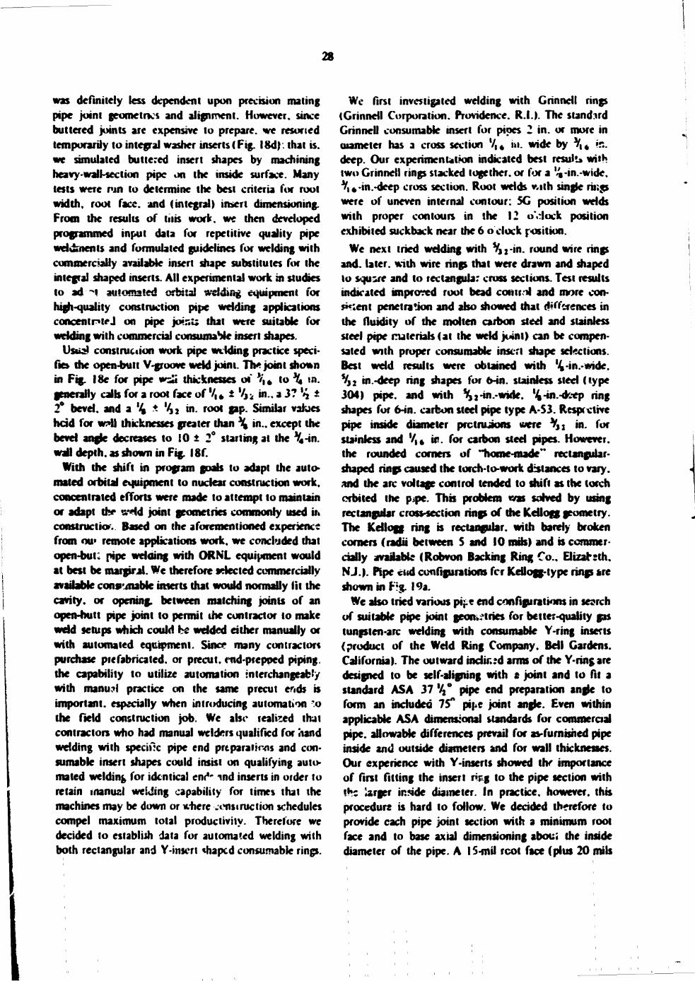
We next tried welding with Vjj-in. round wire rings and. later, with wire rings that were drawn and shaped to square and to rectangular cross sections. Test results indicated improved root bead conUv-4 and more cons e n t penetra*Jon and also showed that differences in the fluidity of the molten carbon sted and stainless steel pipe materials (at the weld joint) can be compensated with proper consumable insert shape sdections. Best weld results were obtained with Vin.-wide. V,2 in.-deep ring shapes for 6-in. stainless sted (type 3(H) pipe, and with %j-in.-wide. ^-in.-deep ring shapes for 6-in. carbon sted pipe type A-S3. Respective pipe inside diameter prctrujons were V J S in. for stainless and V,4 ir?. for carbon sted pipes. However, the rounded corners of "home-made" rectangular-shaped rings caused the torch-to-work distances to vary, and the arc voltage control tended to shift as the torch orbited the pjpe. This problem was solved by using rectangular cross-section rings of the Kellogg geometry. The Kellogg ring b rectangular, with bardy broken comers (radii between 5 and 10 nub) and is commercially available (Robvon Backing Ring Co., Elizatsth. NJ.). Pipe did configurations fcr Kdlogg-type rings are shown in Frg. 19a.
We also tried various pij-e end configurations in search of suitable pipe joint geometries for better-quality gas tungsten-arc wdding with consumable Y-ring inserts (product of the Wdd Ring Company. Bdl Gardens. California). The outward indued arms of the Y-ring are designed to be self-aligning with a joint and to fit a standard ASA 37 %° pipe end preparation angle to form an included 75" pii e joint angle. Even within applicable ASA dimensional standards for commercial pipe, allowable differences prevail for as-furnished pipe inside and outside diameters and for wall thicknesses. Our experience with Y-inserts showed uV importance of first fitting the insert rwg to the pipe section with the iarger ir.5ide diameter. In practice, however, this procedure is hard to follow. We derided therefore to provide each pipe joint section with a minimum root face and to base axial dimensioning aboui the inside diameter of the pipe. A 15-mil rcot face (plus 20 mils
29
ORNl DWG 11 !??40
RECT RING CORNER RADII C-0J6 ,„ 0C10
SSPiPE CARSON PIPE
d DEPTH S » m l l m Mr WIDTH 1 V«t 4J?n> P 10 PROTRUSION 33?." 1 16 tn Rf ROOT FACE 1 16* 1 37 m 1 16 • 1 37 >n
U )
- < l —
AIL DIMENSIONS TYP AND SYMM RF ROOT FAC3 • 0.015 * £££? , n -
0.000 MATING IDs TO HAVE SOME ROOT FACE CONTACT MACHINE ID * AS REQUIRED
lot
Fig. 19. Root face bait joint for U> KeHogg-type manufactured by I he Weld Ring Co.. Bell (ij 'Jenj Calif.
imert and (A) for Y-ring insert. Y-rin* insert comumabk weld ring
30
and minus none) with a 37 V2 ± 2%° end bevel provided for consecutive acceptable root-pass Y-i»sert wddsfFig. I9h).
We have produced acceptable welds with both Y-ring and Kellogg ring inserts but prefer the Kellogg rectangular ring shapes, which provide quality weldmems even wiih poor pipe end preparation and offset matchup oi' the pipe ends to be welded. We were able to produce satisfactory welds as long as there was a minimum contact between the respective pipe root faces and the insert ring; Fig. 19a exemplifies two extreme setups that were weldable with our equipment. Y-insert welding requires more precise limits, as shown in Fig. 19b. ORNL purposely omitted experimentation with consumable EB (Electric Boat Company, Groton, Conn ) type inserts, because EB insert welding requires pipe inside diameter matchup within 5-mil limits, .vhich is too expensive to [wepare for field construction pipe welding.
Welding procedure specifications must be prepared and certified to describe the procedures to be followed for automated gas tungsi n-arc welding of specific pipe sizes and materials in die 2G, 5G, and 6G welding positions with specified automated orbital welding equipment. All welding performed in accordance with the certified procedure should be done by welder-operators who have been thoroughly trained in the operation of the automated equipment and who have demonstrated their proficiency by having passed tests.
PREWELD OPERATIONS
Stored metals will form external oxide coatings which generally are refractory. Extra power (weld current) is required to obtain initial weld penetration when metal surfaces are oxide coated, and even then weld porosity can be caused by hydration of the oxide. Once penetration has been achieved, new problems arise when metal surfaces are coated with oxide. It is difficult to control the weld puddle, especially at or
Procedure qualifications are referenced in the ASME Boiler and Pressure Vessel Code. Section 111. Nuclear Vessels, and are specified in the same Code. Section IX. Welding Qualifications, and in Specifications RDT E15-2T and RDT F6-5T nnd supplements to Sections III and IX respectively.
A certified Welding Procedure Qualification Record must accompany the Welding Procedure Specifications, and list in detail the following information:
1. pipe parent material: 2. electrode and filler material: 3. shielding gas and flow rate; 4. pipe joirt design and consumable insert data; 5. heat treatment data; 6. radiography and liquid penetrant requirements
(NDT); 7. results of destructive test sampling, from duplicate
welds in each of the three welding positions: tensile, root bend, and face bend.
A Welding Parameter Record which lists all the input selections to the programmer-controller is also required for each weld. See Appendix B for a sample welding procedure that is applicable to any automated welding system.
near the overhead weld portions, and weld deposits are uneven, with balling tendencies and void inclusions.
For these reasons, routine cleaning by 3t Jnless steel wire brushing to remove oxide coatings an*i wiping with solvent to remove surface dirt and grease traces are necessary for all welds with automated orbital equipment. Additional draw filing, or grinding, may be required for filler passes to remove sharp notches or protrusions and obtain a smooth, blended substrate.
6. Welding System Operations
31
Joint mismatch, one cause for pot* root pass welds, especially in the pipe horizontal position, is most critical in the "overhead." or 6 o'clock location. A slight mismatch of adjacent edges of the joint's inner diameter causes the welds to pull out or suck back metal due to gravity. It is recommended that the bottom pipe quadrants be matched most precisely for bes welding results, since misfit conditions can be 'olerated to a greater degree in the top quadrant area. Pipe joint mating surfaces should preferably make physical contact to both edges of th? consumable insert on fitup. Purge-gas iosses are minimized with contacting surfaces, and needs for filler wire are reduced. Pipe ends to be joined by welding must be rigidly held in position during welding to prevent weld-heat-induced pipe movement at th: joint due to expansion and contraction. Pipes may be clamped or tack welded prior to the root pass.
There is a difference in ionization potential of inert gases which affects tlie arc voltage and therefore the heat input to the weld zone. Helium requires only about 60% of the welding current required for an equivalent weld with argon shield gas due to the increased arc voltage. Different arc plasma shapes result: argon spreads the weld heat, while helium concentrates the heat. Since wider argon piasmas give best results for stainless steel welding, all ORNL work was done with argon shielding gas. The pipe interiors were purged with argon usually at approximately 20 cm gas flow. The exit orifices or flow openings for the purge gas should be approximately equal in flow capacity to the inlets.
Electrode configuration tests have indicated that better welds can be obtained by tapering the- electrode to a 30° included angle and providing a minimum rounded-off apex. Electro*?*' configuration has a strong influence on the arc heat pattern. The tendency of an arc to spread to an adjacent ares causes the weld nugget to fuse only intermittently and can cause incomplete fusion at the joint sidewalls, leaving an uneven surface appearance on the weld bead. It is practically impossible to lay acceptable fill passes over such defective weld beads and. of course, not recommended; one must resort to corrective interpass machining and blending prior to proceeding with further welding
The angle of the tip of the electrode determines where the arc will initiate. Arc emission can occur from any spot of the heated electrode's tapered emitting surface. Weld bead shape can be somewhat varied by changing electrode tip angles: however, precision, caution, and care are required even with AVC regulation to confine the arc emission to the desired direction so that it will not bump into pipe joint sidewalls. Additional
precautions are necessary to prevent con .acting the electrode with the filler wire during the overlap portion of the weld. The wir'* feed motor cutoff point must be programmed to stop in the initial downslope oortion of the weld current.
Tracking capability of tru. carriage* is adequate for pipe welding operations on horizontal pipes. The driver and idler rollers are designed to include two '^-in.-wide metal lands, one at each end of the 6-in.-wide Vitoi! rubber roil tread surface. The lands project to within 0.005 in. of the rubber surface, so that when the rollers are clamped to the pipe, the rubber is deformed at the point of contact to the extent that die metal lands contact the pipe surface. The traction obtainable from these rollers drives the carriage around the horizontal pipe with a maximum deviation of about 3 to 6 mils per orbit. No compensation is required for this amount of drift, and nc end restraints are required for welding pipes from horizontal to 15° slope positions.
However, when welding on pipes that slope more than 15° end restraints are required in order to keep the rollers from slipping. These restraints are either in the form of split circular ring collars or sprocket chains which _ue clanp^c .o the pipe. Nylon or Teflon bearing surfaces are provided io minimize rotational friction between the orbi ing carriage and the restraint. Wren the split circular ring clamps are employed, primarily for the smaller pipe sizes, plastic buttons ire attached to die carriage end plate to reduce friction. When the sprocket chain is used, for the larger pipe sizes, we exchange all standard link pins in the chain for extension pins to which we moun* the plastic roller buttons to "ride" the carriage end plate. Exter-sion linlcs may be added or removed to adjust the chains to fit over a variety of pipe diameters.
AH clarr.r-ng devices for use in stainless sted pipe for RDT work niust be made of stainless sted. Marker gages must be prepared and applied '.o properly locate afl restraints uniformly from the weld joint. It is necessary to tap the links wifr a ham.ner to line :hem up before tightening the circumfetcr.t'-J chain band.
GUIDELINE: FOR TACKING CONSUMABLE WELD INSERTS
A consumable insert ring should always be tack welded to at least one side of the pipe joint. ORML developed special C-clamp jigs to hold the inser? in proptr alignment while it is being tack welded, since proper and uniform spacing relative to the pipe end and inner pipe diameter is critical, particularly for carbon steel pipes. The amount of nng material protruaing into
32
the inside diameter of the prepared root face of the pipe end must be carefully controlled to attain an acceptable root pass. The insert is supported by the clamp and held in position over the pipe end: the tack welds on one side of a joint should be about 1 in. apart. When tacking an insert to both sides of a pipe joint, the tack welds should be alternated to the respective pipe ends, with at least six approximately equally spaced nick welds around ~ach pipe, or so that they are no more than 3/ 4 in. apart, whichever distance is smaller. These spacings should prevent breaking of tacks during root pass welding. It is important that some filler wire be used for all tack welds to Y-inserts, since there is a tendency to burn aw3y part of the thin edge of the Y while fusion weld tacking the ring to the beveled pipe edge. For gas tungsten-arc tack welding, the arc current should be set at approximately 75% of the rr.can root pass weld current, or about 30 A at 12 V. Both sides of the pipe joint insert must be tacked unless clamps are used to compress the joint for the root pass weld, in addition, the p pe ends being joined must be rigidly held T. position during welding to prevent movement at the weld joint due to expansion and contraction forces.
WELDING TECHNIQUES
The basic principle of gas tungsten-arc welding is to use inert gas to shield the weld puddle of molten metal and the surrounding area where the temperature is high enough to cause rapid oxidation by the atmosphere if not protected. To maintain the inert-gas blanket, the wading must be performed in a quiet atmosphere where no air current or drafts exist. It may be necessary to shield the area to assure a constant inert-gas atmosphere for the weld. Before welding, a minimum of 6 in. of the internal surface of the joint on each side of the weld should be blanketed with argen. The volume of gas for the blanket should be at least five tiir.es the volume of the area to be blanketed, and the blanket should be maintained during welding and until the temperature of the weld falls below 400 F.
CLEANING OF WELD BEADS
Oxide particles and heavy film should be removed from the weld bead and base metal in the line of arc travel before depositing each section or each complete weld bead. Thorough brushing with a stainless steel wire brush is usually required.
DEFECTS
Each weld bead should be visually examined for cracks, holes, incomplete fusion, lack of penetration, overlap, undercut, underfill, and other defects. Each bead should have a smooth surface and contour and should merge smoothly into previously deposited beads and base metal; if it does not, repairs should be made.
REPAIRS
Weld defects can be removed by grinding, chipping, filing, or machining, and appropriate operations -Jiould be perrormed to obtain a smooth surface before depositing the next bead.
WELD SCHEDULE DATA SHEETS Table 1 is a typical data sheet for our system giving
the programmer input information for the root and subsequent filler pass welds. A final, governing weld parameter table wfll be prepared and issued at the time of procedure qualification; that must be followed to achieve good weld results. Limits, or tolerances, for respective data input as normally listed for manual welding practice are ouiitted from die paroneter data since the automated controls, when in calibration, will maintain their built-in tolerances Calibration procedures and test checks are provided with the instruction manuals furnished with the equipment.
OPERATIONAL PROCEDURE (ORNL EQUIPMENT) CHECKOFF LIST
1. Prewdd 1. Verify mat th- pipe joint « tup for welding
meets the following criteria: (a) cleanliness, (b) proper end preparation for both sides of
the joint, (c) proper insert - insert spacing and location
within the established dimensional limits, (d) insert in contact with both pipe ends and
properly tacked. 2. Check purge-gas supply and regulate proper
purge flow to the work piece. 3. Check water flow and torch purge-gas flow to
the weld machine. Gas flow should be 14 cfh minimum and water flow should be about % gpm at approximately 20 psi. Use pressure regulators to protect water hoses, passages, etc.
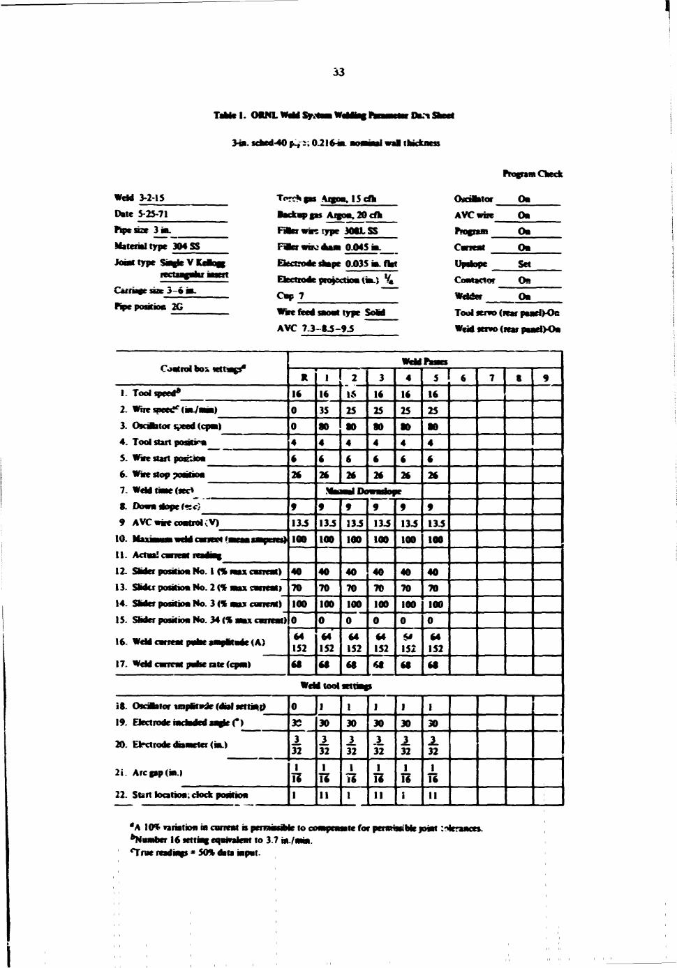
33
Table I . OIWLW«MSyi*aaW«|deaf Ihc%
3-tascBed-40p-,:;0 2M wal thickness
nosjwn Check
Went 3-2-15
Date 5-25-71 Pipe size 3 ML
Matenaltype 304SS
Joint type Sa»fte V Keaoas
Carriaftt SOB 3-6 m.
KpepositioB 2G
Tokens A n y . lScfh Backapgas Afgoa,20cfh BatovaRtype 306XSS
dkaai 0045 i t
Electrode shape 0.035 in. flat
Eixtiode projection tin.} %
Cap 7 ~
Whe feed sMMt type Sold
AVC 7.3-0.5-9.5
Oidantor On AVC woe On P*ocraa On Carrent OB
«P*»pe Set
CoMSCfOT O B
Wader OB
Tool servo (rear panetVOs
Went servo (rear paneiyOn
Control box tetfengs*
I. 2. 3. 4. 5. 6. 7. 8. 9
10. 11. 12. 13. 14. 15.
16.
17.
Tool speed*
Wire; (•L/l
Oscdtator speed ( Tool start poscHi Wire start posaon Wire stop position Weld thae (sec* Down dope (•:<:} AVC (V)
Actaa!
Slider position No. 1 (% SMdtr position No. 2 (% Slider position No. 3 (% Slider position No. 34 (%
carrcat)
estreat) entreat)
Weld carreat pahe j a j u l f ac (A)
Weld carrrat pake rate (cpm)
16
134 100
40
70
100
64 152
16
35
2
1$
25 16
25 SO
16
25
13 J
100
70
100
64 152
13.5
100
40
70 100
64 152 68
134 100
40 70 100
64 152
60
134 100
40 70
100
is 152 60
16
25
134
100
40 70
100
64 152
Wddtoot
18. Oscdhtor wtpttade (dial settinrj
19. Electrode iadadrd aaate C)
20. Etrxtrode dnineter (in.)
2i . Arcpp(ia.)
22. Start kxatioa: dock position
3S
± 32 1
1 *
I
30
32
16 11
30
J. 32
16
30 _3_ 32
16 I I
30
J. 32
16
30
J. 32
16
I I
"A 10% variation in current is pcrnwwMe to *Nwnber 16 setting eaajvalenf to 3.7 in./ Tree readings * 50% data iapat.
compensate for permissible joiat :'Frances.
34
4. Position the carriage component on the pipe, and align the torch head slot directly over the joint.
5. Use Allen wrench to tighten carriage arms to pipe. Note: Torque an equal amount on each arm entil rollers are snug and even. Torque required is approximately 75 in.-lb. Do not over-torque.
6. Connect the control cable to carrage. 7. Check the six cable connections on rear of the
programmer.
8. Turn on power to programmer. This activates power to the carr»g*.
9. Check operation of the carriage, forward and reverse. Forward speed is regulated from the programmer by adjusting the tool speed control, which reads inches per minute travel. PuD knob out. set desired speed, then push knob in io lock. Reverse speed is a constant, fast speed and has no adjustment. Note: Always be aware of the control cable position and do not let if hang on some obstruction because this wffl damage the connector wiring.
10. Turn power off at prograrrcner.
11. Install the wdd hew* assembly into the carriage. Do not fore, it in place, as the wiring connector may be sngt-rJ/ misaligned.
12. Raise cover on the weld head.
13. Turn power back on to programmer. This activates power to the weld head and carriage.
14. Check out the osrillator component of the weld head. (a) The oscillator speed control is regulated
from the programmer. Put! knob out. adjust speed, push knob in to lock. Indication is given in cycles per minute.
(b) The swing or travel distance k regulated by the control knob on the oscillator component in the weld head. The maximum swing spans % in.
(c) Activate oscillator to check by pushing control button on the 'veld head.
15. Check out the wire feed component of the weld head. (a) Check parameter table for correct wire
material and size. (b) Wire feed '.perd H regulated from the
programmer. Pull knob out, adjust control
to desired speed, push knob in to lock. Indication in inches per mjni'te.
(c) Match the alignment marl on the wire feeder cap with the first mark on the cover piece. This permits the wire to manually advance into the feeder's gear drive. Now tighten the cap by rotation until the caps alignment mark matches the second alignment mark on the cover. This provides proper gear tooth tension c*t the wire for motorized wire travel through the feeder. Verify wire advance by pushing forward wire travel button on weld head.
(d) Push the wire retract button on the weld head momentarily to verify reverse wire travel.
(e) Position the filler wire directly at the outlet of the feeder's nozzle.
16. Turn power on to the wdd machine to check *he torch cover gas and water flow - approximately 14 cfli gas and approximately \ gpm water.
17. Turn power off to weld machine.
18. Check out the torch head. (a) See parameter table for proper size of
electrode, electrode angle, ind tip. (b) Position electrode in torch extension and
tighten. Tungsten tip to protrude about % in. beyond the ceramic torch cup.
(c) Screw extension into torch 'lead and tighten.
(d) Check electrode and extension piece to be sure desired depth can be reached by the electrode in the pipe joint. Use Teflon spacer between the extension piece and the ceramic cup if needed. If ir.oi.- depth is desired, use a copper spacer between the torch head and the extension piece. Do not use Teflon between torch h ad and extension piece. Spacers should be used to allow the electrode to touch bottom of joint on root pass. This will leave \ in. movement upward or raising length for fid P9S0CS*
19. Check the horizontal and vertical adjustments of the weld .lead. (a) V.jt horizontal adjustment is made by
rotating a knob on the outside cover of the weld head assembly, which moves and
35
locates the components of the weld head to the desired area of the pipe joint. When the'electrode is in the center oi the joint, the horizontal adjustment should be in its midrange. or at the center of its movement. If necessaiy. relocate the carriage to acquire this position.
(b) The vertical adjustment is motor driven, with the controls located on the re.TH>te weld pendant control. The motor is mounted on the outside cover of the weld head. The motor shaft alignment is critical, and all caution should be taken no! to abuse the motor housing or its holddown clamp.
(c) Energize both manual pendant controls and check to see that both directions, up and down, are working correctly.
(d) Adaptive vertical control is maintained during welding operation through programmer sensing circuits. AVC control settings for the programmer are listed on the weld parameter data sheet.
20. Reverse wind the car.iage one revolution *o get the cables in proper position to unwrap from around the pipe during the weld operation. Clear any obstructions that may tend to interfere with the cab!*.
21. Rewind carriage about 2 in. past start point and then move it forward about ! in. in weld direction to remove any XKsrble slack m the gears that might cause a rough start on the weld pass.
22. I f wiie ft*d is to be used, check the guide nozzle position. The direction of the wire shou'u be guided directly from the nozzle end into the weld puddle. Wire should not touch the weld surface or joint sides before it reaches the puddle. Wire should enter the ->\treme front area of the weld puddle. A set
rew is used to lock the nozzle in position.
23. Use the weld parameter data sheet to make all settings on the programmer.
24. Set all welding machine switches and selectors to the proper positions indicated:
Remote current control On
Mode selector - Straight dc ( )
Soft start Off
Spark - Start only
I I .
Current range selector Medium
Side switch < program control position) Up (light is on during welding)
Fine adjustment control =10
Gas afterflow =50 < max)
Gas welding selectoi - Other types welding
Spark intensity =10 < max •
25. Close weld head cover and lock.
26. Turn weld machine power on.
27. Locate remote power control pendant dose to work area.
28. Welding operation K now ready to begin.
1. The following items have been checked. (a) The elect,ode position has been placed so
that the initial «c w i l strike on the joint side if c3c3htion is used.
(b) If osciUarkv. is required, die span of the electrode wit not toiacti the joint sides.
Oscillation of the weW torch helps to assure fusion into the sidewah. When used in combination with current puking, osculation w i l also help to maintain a stable weld puouk. The oscflatkn ampiitnde can be varieu »ip to % in. width, and the oscillation frequency can b* coatroled.
Osculation amplitude (side nt'fference) checks should be nude prior to each pass by depressing the OSC button on the weld head lid body.
<c) The electrode gap from tip to work has been set at approximately '4 in., and the adapting vertical control settings have been entered on the programmer.
2. Press start button on the nendant contioi.
3. G'ncrve through port in carriage to check weld operations. Always keep pendant control dose by to be able to push the downvope button or the stop button in case of an emergency.
4. Whenever potable, stop the welding operation by pushing the downsfope button on the remote pendant control. This action protect* the good weld already made. I f the stop button is used, the weld can be damaged by the filler wire sticking to the puddle area and/or the purge gas being cut off too quickly.

36
5. Downslope the weld operation after each complete orbit is made.
6. Revere wind the carriage to properly arrange the cabks around the pipe prior to each weld p*ss.
7. Always overlap the previous start point on the reverse wind so that on the next start, all sLck in the drive gears will be out and no backlash motion of the carriage will affect the weld head. Stagger subsequent weld starts by at least 1-in. spacing*.
*. Lift the cover on the weld head and check the eicctrodc aiigie and tip. A close watch on the arc voltage will also indicate when an electrode should be changed or reshaped.
°. Position of starts should preferably be somewhere between 10 and 2 o'clock. Viewing through the weld head's viewport is easier: it permits adjustments in an area least vulnerable to operator regulation assists.
10. Follow weHJ parameter sequence selection 'C^ommetidations.
GUIDELINES FOR THE WELDER-OPERATOR'S VISUAL OBSERVATION
DURING AUTOMATED WELDING
As mentioned previously, i: is recommended that sluBed manual welders be selected for training to oper«:e die ORNL automated orbitai pipe welding system. The welder's experience is invaluable, not only in properly assembling and locating the torch, etc.. but also in detecting minor discrepancies that might occur during operation. Lack of proper remedial act«in by the operator can ruin a w*ld.
Ideally, each weld system should include a recorder *.o plot variables such as torch travel rate, welding current, arc voltage, and wire feed deposit rates. The recorder chart can be used during operation to detect functional deviations and to guid* and verify the operator's corrective action. For automated systems without separate chart recorders, it is possible to observe the console voltmeter and the wire feed rate meter to attain some indications of weld pass quality. Both meters
indicate variations in arc length. A root pass weld is not penetrating the joint fully if voltage readings hold steady but the feed rate registers only below the selected rate. Usually, a small increase in welding current will remedy this situation. If. however, the wire feeder motor builds up to the selected set rate and voltage continues to climb, poor welding also results and the cycle should be stopped at once. Now the problem will usually be an excessive joint gap formation with too much push-through in the upper quadrants of the pipe, filler wire bound up within the wire feeder drive and not feeding into the weld, or excessive puddle fluidity in pipe vertical positions causing puddle flow away from the electrode tip. Investigate the problem with tr*; machine off. Satisfactory weld fill passes do not appear to present great problems. The second weld pass, or first fill pass, requires some special care in properly adding L';C finer wire and obtaining weld buildup without root pass bum-through. Heat input selections for this and subsequent passes require only fusion to the previous pass and to the joint sidewalk. Oscillation of the wdd torch help< to assure fusion into the sidewatl. and current pulsing tends to maintain a stable weld puddle and to smooth out minor weld puddle perturbations.
Few programmer input changes ore reouired during the initial fill passes, except to add torcii oscillation and to adjust, or set. the wire feeder exit nozzle to a proper entry angle with the pipe jcTit surface. Final fill passes can be made with increased weld power, wider oscillation, and increased wire feed. A near 12 o'clock start position for the first fill pass (for 5G position welding) generally helps to balance partial distortion of the pipe created by die root pass.
One procedure for rilling local wdd areas that have been purposely ground out to remove weld defects is to place the carriage about \ in. in front of the area to be filled, set a short arc gar* of about %i in., and in tiate a weld cycle. After the carriage traverses the recessed area, the AVC wire feed control will start to automatically add wire as soon as the arc gap increases. If the localized defect is not too severe, the AVC and wire feed additive controls will automatically fill the depression to the level of the surrounding substrate during subsequent filler passes.
37
7. Welding System Maintenance
Detailed instructions for mechanical maintenance and electronic calibration checks are given in the Operation and Maintenance Manual for ORSI.-Furnished Automated Welding Systems. The Manual also includes a chapter on "Malfunction Data," plus suggestions and/or procedures for corrective maintenance actions, and disassembly and reassembly directions for the carriage and the weld head. Guidelines are offered for troubleshooting every functional programmer-controller circuit and for the plug-in cards.
Routine daily maintenance requirements for the welding equipment include visual checks for obvious abnormalities and for general cleanliness. The carriage and weld head shou'd be stored in appropriate dustfree boxes overnight and whenever not in use. The carriage arm assemblies should be slightly untorqued to minimize roller pressure against the pipe and thus prevent permanent Viton-rubber tread deformation where inter-pass temperature controls for welding call for considerable delays between passes.
Biweekly preventive maintenance cnecks for the equipment should include programmer calibration checks, particularly for orbit travel speed and wire teed rate. Nonroutine carriage maintenance operations should be conducted as necessitated by operational needs; troubleshooting procedures recommended in the Manual should be followed.
Cleanliness is required for proper operation and maintenance of the equipment. Driver and idler rubber roil surfaces must be kept clean by wiping with acetone: chips and dirt r»*ust be removed fro.n all crevices; and bearing surfaces must be coated at all times with a light film of high-temperature lubricant. The carriage, weld head, programmer-controller, and, where possible, the recorder should preferably be kept away from dust, dirt, and rain. A ventilated, boxed enc'osure has been designed and is available to house the programmer and a recorder for field operations. Clean air is circulated through the box to retain a sligh'. pressurizatiun within the enclosure to seal out dust and dirt.
8. Operator Training
Operator training consists in instructions in the setup, calibration, control, operation, and maintenance of the automated orbital welding and programming equipment. ORNL conducted a two-week training program for Bechtel Corporation operating oersonnel from Westinghouse-Hanford and for TVA personnel from the Browns Ferry Nuclear Plant utilizing the Operations and Maintenance Manual for the Oak Ridge equipment system as a text !o supplement the practical training. The practical training involved a one-week period for t-ecoming acquainted with the equipment followed by a week oi specialist training held in split sessions for both the weld operator ?nd the electronics maintenance engineer. We purposely requested that the trainees include someone with a broad manual welding background and someone knowledgeable in automated
electronics system operation and upkeep. The second-week training sessions involved the mechanic J and metallurgical aspects of weld technology for the welder, plus electronic control, programming, troubleshooting, and maintenance for the instrument systems specialist. The welder-operator actually . * up and executed a number of automated welds, while the electronics man performed controller checks, calibrations, and electronic repairs. The trainees also received instructions in the interpretation of mechanical and electrical drawings for the ORNL syrtem and were issued Manuals and blueprints at the time of their departure
The dual-phase training program, theory and practical work, effectively proviu*d i-ach trainee with a balanced overall background of automated welding technology and practice. Exposing the welder trainee to some basic
38
instrument, programming, and contro' techniques and practices, and acquainting the electronics trainee with actual welding routines helped each to appreciate ard comprehend the specitk involvements and problems of the respective expertises. Good automated welding practice call* for a "team effort" of specialises. The instrument man can often provide the welder with
The Riost important objective in cutting and preparing pvt<c ends for welding is to obtain precision geometrical and dimensional symmetry forrr:atir_ pipe ends. This statement holds 'rue for all types of wt'.d joints. Unfortunately, commercially available p.pes are routinely cut-of-round, noncosicentric between inside and outside diameters, and of uneven wall thickness. These irregularities make it impossible to rely on simple, rapid machining cperat:ons to establish the ideal pipe end geometries for weld joints.
ASME Materials Specification. Section II, Boiler Code for Piping, describes the allowable dimensional variations in the diamete- and wall thickness of various types of pipe. Section SB 167, for N«ckcl-Chiome Alloy Pipe, for example, permits an allowable eccentricity e pipe inside and outside diameters up f> 10% of the nominal wall fhiclness: even comparable SA 106 carbon stee! pipe specifications allow for 12%% thickness variations. Diameters for large piping may vary a much as Vg in. All commercial pipe is governed by these specifications. Our experience indicates that piping dimensions vary at least as much as, or slightly more than, the allowable tolerances. Furthermore, the* manufacturing process of pipe: in the mill is based on squeeze rollers ibout the pipe's outside diameter, resulting in primary, or best, dimensional tolerance control of the outside diameter and least control of the inside diameter The pipe joint to be welded, however,
adequate controls to maintain certain required torch-to-work relationships if he ts taught to understand what constitutes the proper weld. Also, a weld operator who understands how the controls interact, why time delays occur in control responses, and what control factors influence repeatability can then select the programming parameters essential for consistently good weMs.
requires closest matchup tolerances for the root bead pass 2i the pipe's inside diameter and only nominal control at the outside.
Piping for nuclear work often requires special mill rolling for above-average material composition control adherence. Dimensional pipe specifications also require strict tolerance limits on the diameter and wall thickness but realistically must conform o dimensional control limits of the manufacturing process. Hence, it becomes necessary to establish pipe roundness and inside diameter contro! by requiring inside diameter and root face machining. Standard lathes are usually employed for end preparation in the smaller pipe sizes; clamp-on, track-operated frame lathes4 are often used to properly prepare end: for the larger pipe sizes. Care must be exercised to retain the specified pipe v/ali thickness, and the designer should always specify sufficiently heavy pipe walls to end up with at least the minimum required pipe wall thickness after machining. It is also important that the stress analyst study all joint configurations to provide allowances for uneven w?!' thickness near the finished v*cld joint ana examine the weld-he.;f ..hrinkage-induced pipe comour deformation at the weld joint.
4. Pipe-end preparatk ', machines are manufactured by the K&M Pipe Beve!*ng Company, Tulsa, Okia.. and by others.
9. Cutting Prerequisites - Pipe Cut and Bevel Preparation Development
39
10. Commercial U.S. Equipment Sources for Orbital Welding Systems
To the best of our knowledge, as of JuJy |37_\ the following companies are the only manufacturers of automated tungsten-gas orbital pipe welding equipment in the United States:
Astro-Arc Company, Sun Valley. Calif.
CRC-Crose International. Inc.. Houston. Tex.
Dimetrics, inc.. North Hollywood. Calif.
Liquid Carbonic Corporation, Des Raines, ill
magiiatrch, The DSD Company, East Grandby, Conn.
Rytek. Inc., Santa Fe Springs. Calif.
TekTran Company, Newark. Ohio
Zeta International Engineering. Inc.. Santa Clara, Calif.
A number of companies in Furopc also market equipment systems that are qune similar to the Liquid Ca. oonic line. The above list includes only companies producing equipment for orbital torch tr?y<:\ icvut a stationary p<pe. Most of the major welding e<,i ipment manufacturers build automated, or at least serruau o-mated, tungsten-gas torch equipment for use m applications where the pipe rotates pas* a stationary tcrcli.
The Astro-Arc pipe we!<i system can accommodate a pipe range from 4 to 36 in. OD. One guide ring and one disposable belt are required for each diametral size increment. Two-section hinged guide rings are available for use with pipe sizes up to 12 in., and segmented link tracks are useu for 12- to 36-in.-diam pipes. Links are added or deleted for the in-between pipe diameter sizes, and all tracks ire grooved to seat the inexpensive special cloth belts. The Astro-Arc carriage, containing the torch, wire feeder with a 4-in.-diam spool, oscillator, and orbi» motor drive, includes a rugged spring mounting for the bel! attachment. The Astro-Arc power supply is solid state. 200 A GTA, fully transistorized, and includes an integral liquid-cooling system. Programming includes I V2-in. AVC t. ch travel idjustment at approximately 60 in./riin AVC compensation speed, 10 to 100 cr>m oscillation frequency for up to V -in.-wide oscillations with independent dwell stop capability per side, and several modes of pulsed current operation. The Astro-Arc solid-state programmer is house..' directly on top of *.he power supply. The system also includes provisions >>r future plasma arc attachments.
CRC-Crose International. Inc . is a subsidiary of Crutcher-Rolfs-Cummings. Inc. Their automatic pipe welding system employs the gas shielded-arc welding process with multiple torches mounted to the pipe both internally and externsliy. The system also includes an integral hydrauhcaily powered machine to prepare and align pipe join is in the field. However, the machinery, buiii primarily for large overland pipe lines, is butty and very heavy and does not lend itself for highest-quality nuclear-grade gas tungsten-arc welding.
Dimetrics, Inc.. like Astro-Arc, is an inc*oendent company that produces solid-state power supp..es and specialty tube and pipe welding equipment. The company is presently developing automated chain-driven orbital pipe welding machinery for interchangeable gas tungsten-arc or gas metal-arc welding to be marketed to supplement their standard rolled-work AVC controlled stationary torch equipment systems. These systems feature programmer-controlled power supplies in various power ranges for operation in multiple pulsed welding modes.
Liquid Carbonic, a subsidiary of the Houston Natural Gas Corporation, has taken _/er the manufacture of automated machinery systems originally developed for the Navy by the Electric Boat Division of General Dynamics at Groton, Connecticut. Their APW series machines employ a split gear to carry a combination torch, torch oscillator, wire feeder attachment. Tin gear is enclosed within a hinged circular housing track, md a stationary motor mounted to the track orbits the geai-torch combination about the pipe. The balance of the system .omprises a soi.d-state control console and a pulsating arc dyna-surge power supply. The GTA system will accommodate from 3- to 36-in. pipes.
Magnatech, th<: DSD Company, entered the tube and small pipe auf"-nated welding field by adapting a home-built tube welder used ;•• the manufacture of their prtcLion metal O-rir.^Turoseals to an inexpensive orbital welder which they now market commercially. The equipment is prtjcntiy limited to gas tungsten-arc welding of square-cut. butted pipe joints up to 1 % in. in diameter with wr,!» thicknesses up to 3 / ! 6 in. The automated, pr.^ami/ied fu«ion welder consists of a mechanical pro>. irr.wj and a weld head built to accommodate cur 'n tribes and pipes as well as straight runs. The equip' .^.i: incorporates simple mechanical
40
devices for preparing the weld program and a program profile cam disk. The programmer plays back the cam card to obtain the automated control of welding parameters. The automated system operates in conjunction with any commercial GTAW power pack. Magna-tech is presently enlarging their welder line and adding wire feed and oscillation capabilities to their equipment in order to handle larger diameters &nd heavier wall thicknesses.
Rytek, Inc., recently went 011 of business, but, according to i*s owner, Henry Rygiol, th? operation apparently is being reinstituted as part of the Susquehanna Corporation in San Diego, California. Rygioi has built a number of specialty systems for specific automated gas tungsten-arc applications.
TekTran is a relatively new joint ventuie company formed by the Air Products and Chemicals, Inc., and North American Rockwell Corporation to market automated welding systems and testing equipment. TekTran obtained the detaJed drawings and specifications prepared for our ORNL welding system via the National Technical Information Service to build prototype machinery for evaluation from manufacturing, operational, and servicing standpoints. We understand that TekTran expects to market a series of four automated orbital welding carriages for pipe sizes ranging from 2 \ to 24 in. Their system basically resembles the ORNL horseshoe carriagc-wcld insert design, but the four-roller tractor carriage with two motorized drive:; and two free-rolling idler rolls has been changed to a
three-roll tractor with each of the rollers motorized. TekTran's new line is based around their new 300-A solid-state, SCR-type weld power supply for both gas tungsten arc and gas metal-arc welding. The system will also feature interchangeable weld insert modules for operation in Soth welding modes, with the GMA process recommended for speedier, heavier bead deposits for finai filler passes.
Zeta International Engineering, inc., is the successor to the Bartley Engineering Company. Thei> automated welding system utilizes pulsed gas tungsten-arc welding and pulsed gas metal-arc vrelding processes. The major
onents of the system are: lour welding tractors, :-r tor's control console, wire feeder v*.th junction
box, dual weld power supplies, and a solid-sis*e logic control cabinet. Three of the four tractors clamp onto the pipe and iot?»te the torch similar to most automated tube welders. These tractors are :zed to handle piping % to 1 %, 1 % to 2 %, ant. 3 tc 5 in. The fourth tractor, for all pipe sizes above 3 in., uses a tooling ring which is bolted to die pipe to be welded. A double-row chain is used on the tooling ring to hold and provide means to drive the tractor. The weld tractor* also have as options arc voltage control, oscillation, and cold wire addition. Zeta's GTAW power supply is a 200-A, 100% duty cycle, constant current maclune, with current pulsing available as an option. The GMAW power supply is an Airco model PA-3, modified to make the Z.I.E. system "turn-key."
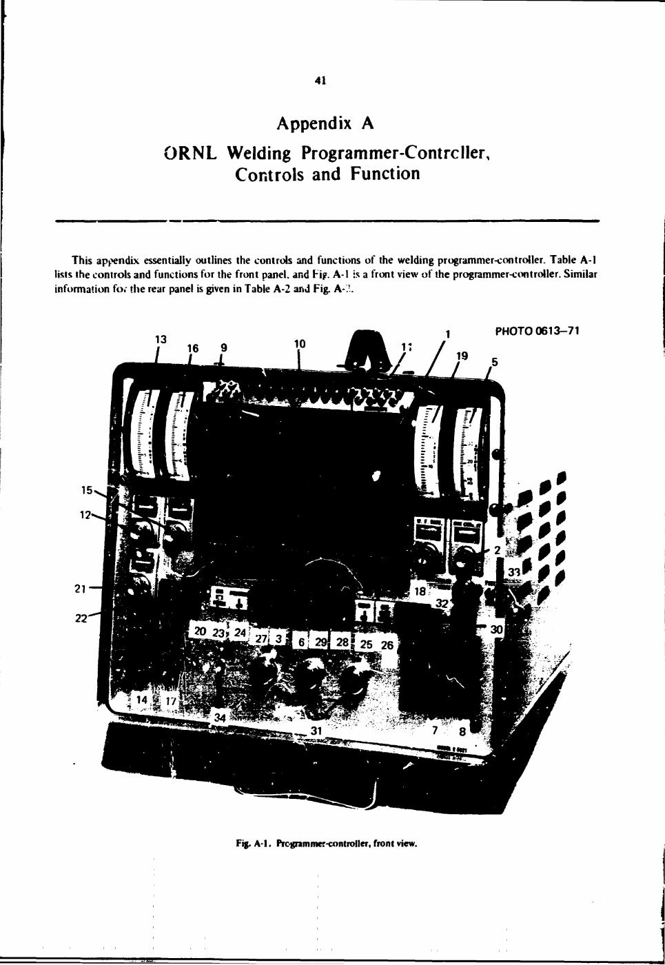
41
Appendix A ORNL Welding Programmer-Contrcller,
Controls and Function
This appendix essentially outlines the controls and functions of the welding programmer-controller. Table A-1 lists the controls and functions for the front panel, and Fip. A-1 is a front view of the programmer-controller. Similar information fo, the rear panel is given in Table A-2 and Fig. A-.'.
PHOTO 0613-71
Fig. A-1. Programmer-controller, front view.
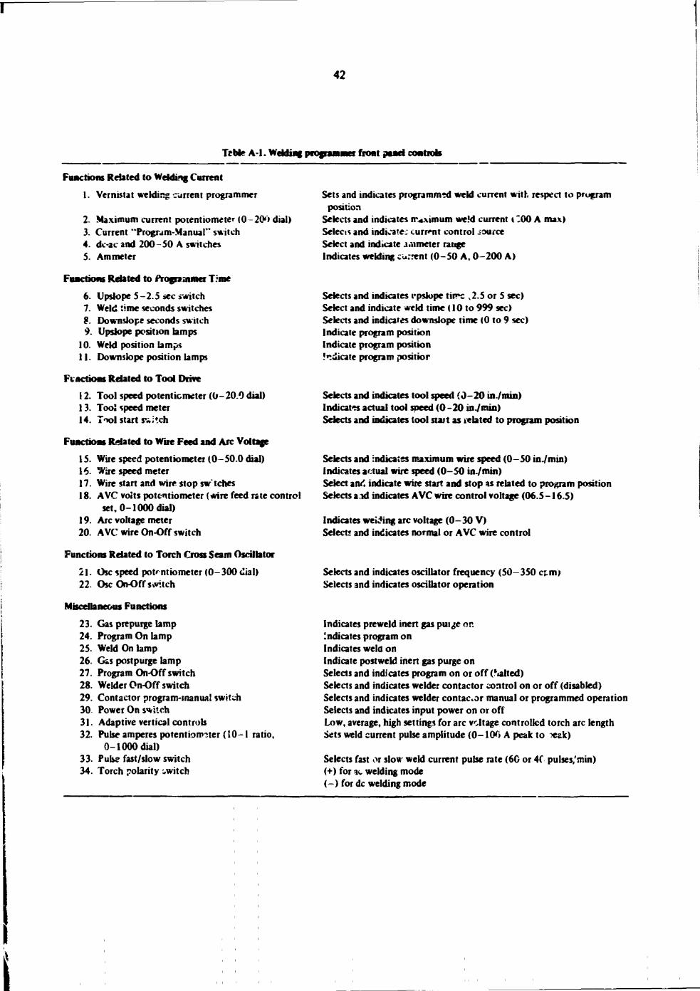
42
Teble A-l. Welding programmer boat panel controls
Fimctiofis Related to Welding Current 1. Vernistat welding current programmer
2. Maximum current potentiometer (0 200 dial) 3. Current "Program-Manual" switch 4. dc-ac and 200 -50 A switches 5. Ammeter
Functions Related to Programmer T:me
6. Upslope 5 - 2.5 sec switch 7. Weld time seconds switches 8. Downslope seconds switch 9. Upslope position lamps
10. Weld position lamps 11. Downslope position lamps
Fi actions Related to Tool Drive 12. Tool speed potentiometer (0 - 20.0 dial) 13. Too! speed meter 14. Tool start s*;tch
Functions Related to Wire Feed and Arc Voltage 15. Wire speed potentiometer (0-50.0 dial) 16. Wire speed meter 17. Wire start and wire stop sw'tches 18. AVC volts potentiometer (wire feed rate control
set, 0-1000 dial) 19. Arc voltage meter 20. AVC wire On-Off switch
Functions Related to Torch Cross Seam Oscillator
21. Osc speed potentiometer (0-300 <lial) 22. OscOihOffsivitch
Miscellaneous Functions 23. Gas prepurge lamp 24. Program On lamp 25. Weld On lamp 26. Gss postpurge lamp 27. Program On-Off switch 28. Welder On-Off switch 29. Contactor program-manual switch 30 Power On switch 31. Adaptive vertical controls 32. Pulse amperes potentiometer {!0-1 ratio,
0-1000 dial) 33. Pulse fast/slow switch 34. Torch polarity switch
Sets and indicates programmed weld current with respect to prugram position
Selects and indicates rruximum we!d current t "00 A max) Selects and indicate: current control source Select and indicate a.nmeter range Indicates welding current (0-50 A, 0-200 A)
Selects and indicates rpslope tirrc ,2.5 or 5 sec) Select and indicate weld time (10 to 999 sec) Selects and indicates downslope time (0 to 9 sec) Indicate program position Indicate program position .'cdicate program positior
Selects and indicates tool speed (0-20 in./min) Indicates actual tool speed (0-20 inVntin) Selects and indicates tool start as related to program position
Selects and indicates maximum wire speed (0-50 in./min) Indicates actual wire speed (0-50 in./min) Select and indicate wire start and stop as related to program position Selects aid indicates AVC wire control voltage (06.5-16.5)
Indicates weiring arc voltage (0-30 V) Select* and indicates normal or AVC wire control
Selects and indicates oscillator frequency (50-350 «.m) Selects and indicates oscillator operation
Indicates preweld inert gas puige or. Indicates program on Indicates weld on Indicate postweld inert gas purge on Selects and indicates program on or off (Salted) Selects and indicates welder contactor control on or off (disabled) Selects and indicates welder contactor manual or programmed operation Selects and indicates input power on or off Low, average, high settings for arc voltage controlled torch arc length Sets weld current pulse amplitude (0-100 A peak to *ak)
Selects fast or slow weld current pulse rate (6G or 40 pulses/min) (+) for 4 welding mode (-) for dc welding mode
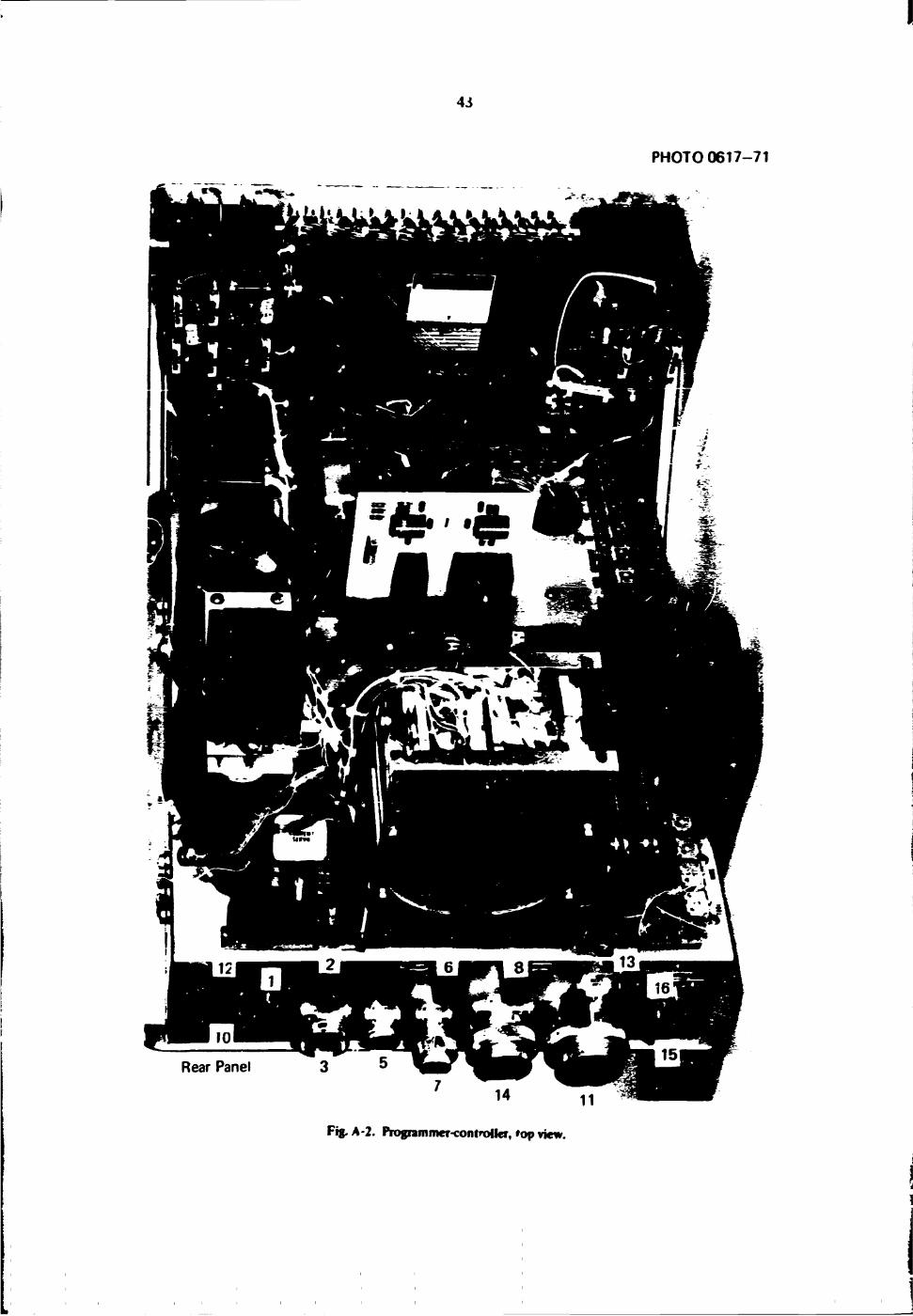
4J
PHOTO 0617-71
Fig. A-2. Programmer-controller,'op view.
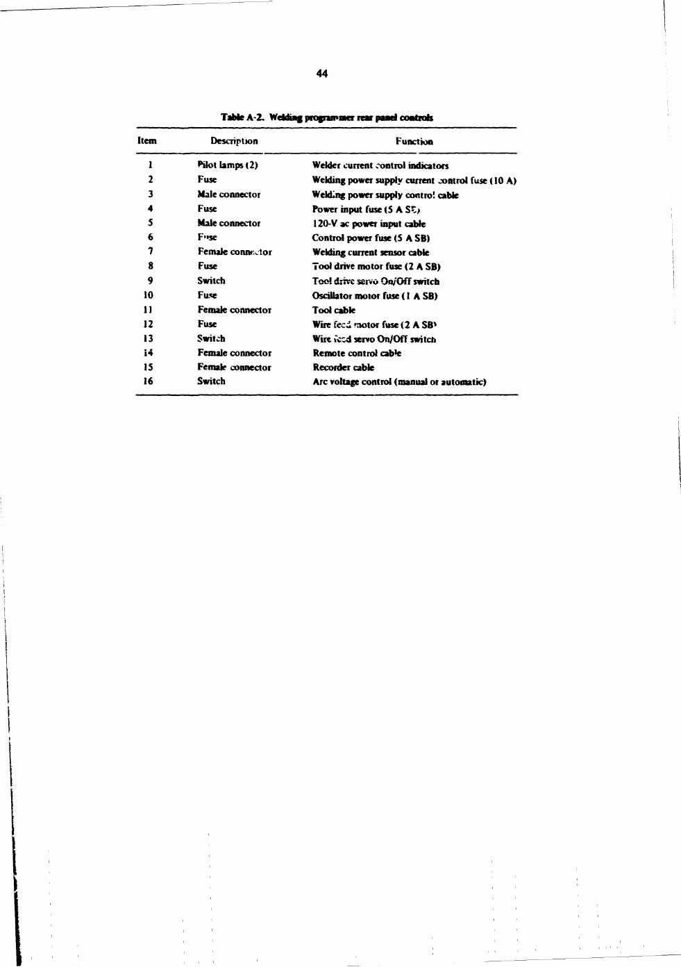
44
TaMeA-2. Welding programmer rear panel coatrab
Item Description Function
1 Pilot lamps (2) Welder current control indicators 2 Fuse Welding power supply current control fuse (10 A) 3 Male connector WekLng power supply control cable 4 Fuse Power input fuse (S A SZ> 5 Male connector 120-V ac power input cable 6 F"$e Control power fuse (5 A SB) 7 Female conntxtor Welding current sensor cable 8 Fuse Tool drive motor fuse (2 A SB) 9 Switch Toe! drive servo On/Off switch
10 Fuse Oscillator motor fuse (1 A SB) 11 Female connector Tool cable 12 Fuse Wire feed motor fuse (2 A SB* 13 Switch Wire iced servo On/Off switch 14 Female connector Remote control cab*e 15 Female connector Recorder cable 16 Switch Arc voltage control (manual or automatic)
45
Appendix B
Recommended Format for Establishing a Welding Procedure for Automatic Welding
The information in this section is intended to assist newcomers to automated welding in setting up procedures for automated systems. Our experience in training jnd in working with people not familiar with automated welding technology indicated the need for simple guide lines along with a list of available procedures for both nondestructive and destructive examl^Lons of welds. A. sample welding procedure is given along with a typical list of general welding parameters (Table B-I). Figures B-l and B-2 iDustrate a joint geometry for weld joints and details of insert tack-weld sequencing respectively.
Sample Welding Procedure Record for Type Welds
A. SCOPE
This procedure record describes the criteria for automated gas tungsten-arc welding of Sched. (Mat! ) (Type ) piping using the (Name of automated system). This procedure is based on use of the (type) consumable insert with an internal (type gas) purge and cold wire feed in the G and G positions. The procedure is detailed here for in. diam. Sched. pipe, and with attached data tab??* (one for each size) applies also to other specified pipe sizes. All welding performed in accordance with this procedure, which meets the requirements of Section IX of the ASME Code and RDT Standards E 15-2T and F 6-5T (supplements to the ASME Code), must be done by welder-operators who have demonstrated their proficiency by passing the qualificatior tests and receiving thorough training in the operation of the automated equipment.
B. SAMPLE PROCEDURE RECORD FOR WELD # 1. Preweld Preparation
Reference: ASME Boiler and Pressure Vessel Code, Section III. "Nuclear Vessels" a. General specifications. ASME Boiler and Pressure Vessel Code. Section IX, "Welding Qualifications,"
and RDT Standards E 15-2T and F 6-5T. "Requirements for Nuclear Components" and "Welding Qualifications"
b. Base metal i. Specification ASTM A 312-64, "Specification for Seamless and Welded Austenitic Stainless
Steel Pipe." ii. Grade - type 304. ii:. Form and "P" number - seamless pipe, ASME Section IX "P" No. 8. iv. Thickness 0.280 in. nominal, v. Diameter 6.625-in. nominal outside.
c. Filler metal i. Specification - ASME-AWS Specification SFA-5.9, "Specification for Corrosion-Resisting
Chromium and Chromium-Nickel Steel Welding Rods and Bare Electrodes." i i . Classification and chemical composition - ER 308. iii. F and A numbers per Code Section IX type ER F7 (Table Ql 1.2), Weld Metal Analysis No. =
A7(TabIeQll.3).

46
Tahi t i -1 . WcManjpai - X Y Z i
Weld* _X sai type JC_
DatcJ(_
r . jK -we.sched^.2^
Mat! JC^. type Jt^
Joint type X
Pipe positiou($) X , X .
Torek fas. flow X^. _X_ efk I
BacJn* gas, flow Jl . X_ cfh !
Pass
Filer wire diaa.. type _X_. _X_ |
Electrode d a n . _X_. shape X
Electrode proj. (torn cap X
Cups X lasert inf •: X
Wrid fool setting
Torch height above pipe surf., in.
Ekctr. tip to wire distance, in.
Oscmator amplitude, in.
Wire feed retract (set at) in.
Went start (dock position on pipe)
Fiuntanunet control box srttiwgi
Arc voltage, V dc (Av.}
Wire feed rate, in./min
Carriafe drive rat«, in./mm
Carriage drive mode
Oscillation, cpm
Dwell time, left side, sec
Dwell time, right side, sec
Carriage drive start delay, set
Wire feed start delay, sec
Wire feed upslope, sec
Wire feed deby, sec
Prepurge timer, sec
Postpurge timer, sec
We'd current, pube high, A
Pube time,' «h, sec
Pulse low current, A
Pulse time, low, sec
Initial current set, A
Current upslope time, sec
Current downslope time, sec
Total weld time, min and sec
Arc voltage set, high, low
WeU| MXKS *
Root 1 . 1 2 i 3 4 5 6
X X X X
X X X X X X X X X X X X X X
11 1 11 1 11 I 11
X X X _ * * X X X _ * *
X X X X X X
X X X —#-X X X —#-
X X X X
X X X — • X X X — •
X X X X
X X X X
X X
X X
X X
X X
X X X X X X X X X X X \ X Y —• X \ X A
X X X X X X X X X X X X X X —a-X X X X —a-X X
X X 1 "" X X
X X X - » -X X X - » -x / X — -x / X — -
a X mrrks the spaces where specific values are to be provided.
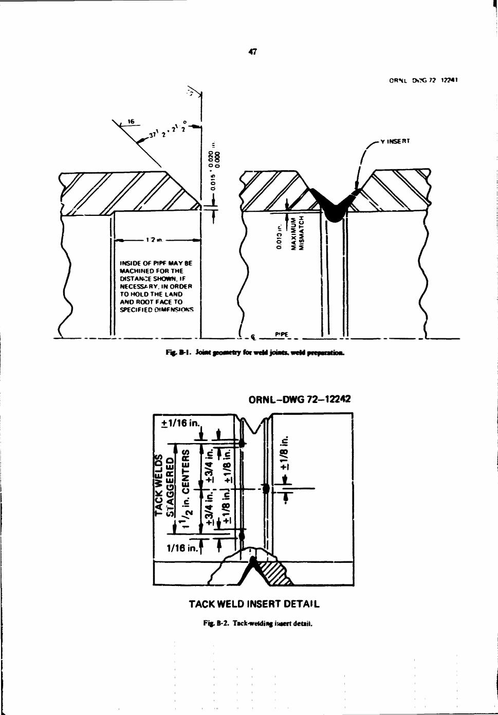
47
ORNl DOG 7? 17741
1 ? m
INSIDE Of PlPf MAY BE MACHINED FOR THE DISTANCE SHOWN. IF NECESSARY. IN ORDER TO HOLD THE LAND AND ROOT FACE TO SPECIFIED 0!MFN$IOK$
Y INSERT
Fij.B-1. Somt
ORNL-DWG 72-12242
TACK WELD INSERT DETAIL
Fig.B-2. Tack-welding iuaert detail.
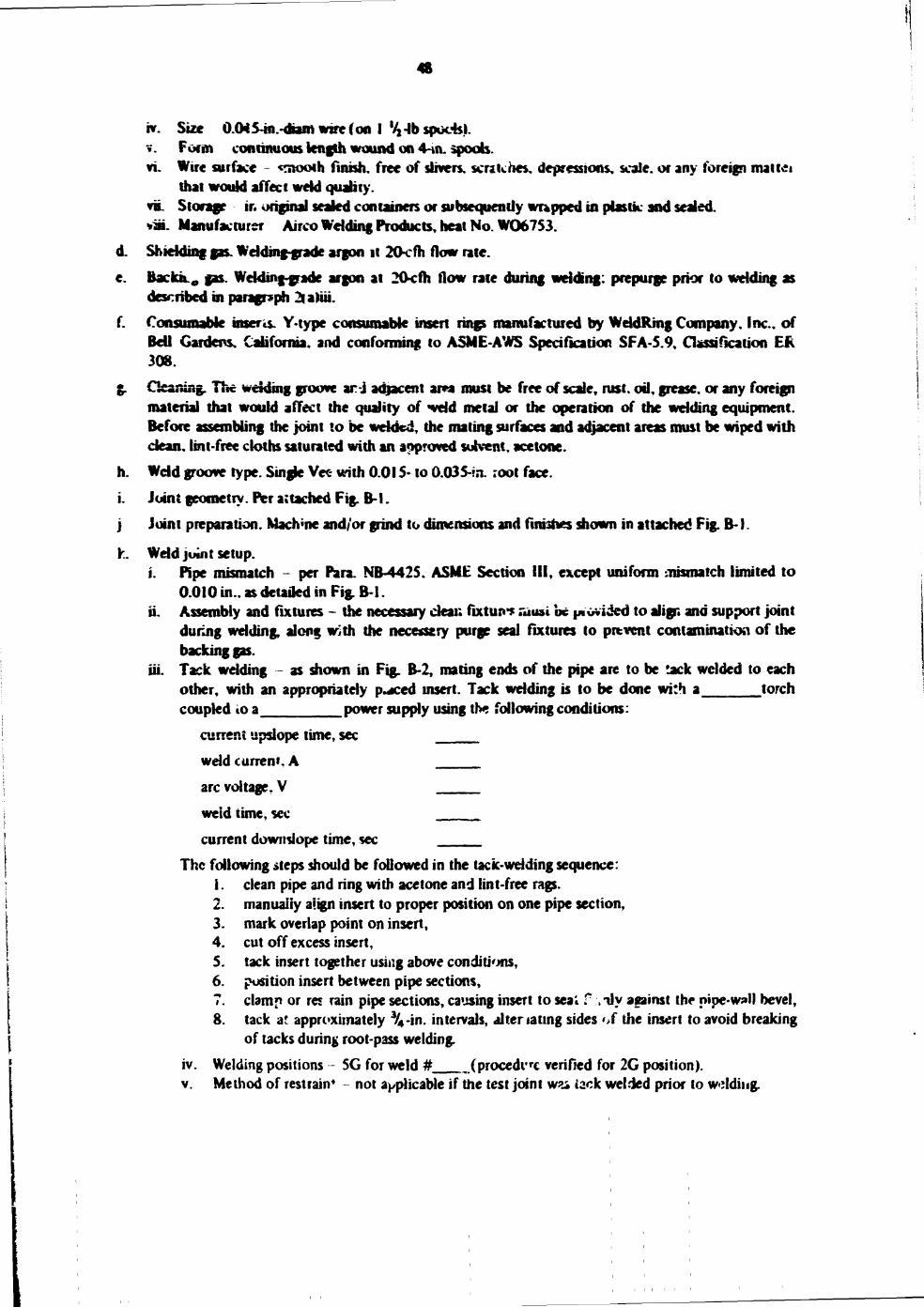
48
nr. Size OXKS-in.-diain wire (on I %-lb spuds). v. Form continuous length wound on 4-m. spools. vi. Wire surface - «nwoth finish, free of slivers, scratches, depressions, scale, or any foreign mattti
that would affect weld quality. viL Storage ir. original sealed containers or subsequently wrapped in plastic and sealed. *m. Manufacturer Airco Welding Products, heat No. W06753. Shielding gas. Welding-grade argon it 20cfh flow rate. Backk0 gas. Welding-grade argon at 20<fh flow rate during welding: prepurge prior to welding as described in paragraph 2|atiii. Consumable insert Y-type consumable insert rings manufactured by WddRmg Company. Inc., of Bell Gardens. California, and conforming to ASME-AWS Specification SFA-S.9, Classification ER 308. Cleaning. The welding groove ar-j adjacent area roust be free of scale, rust, oil, grease, or any foreign material that would affect the quality of weld metal or the operation of the welding equipment. Before assembling the joint to be welded, the mating surfaces and adjacent areas must be wiped with dean, lint-free cloths saturated with an approved solvent, acetone. Weld groove type. Single Vec- with 0.015- to 0.03 5-»n. root face. Joint geometry. Per attached Fig. B-l. Joint preparation. Machine and/or grind to dimensions and finishes shown in attached Fig. B-l.
Weld joint setup. i. Pipe mismatch - per Para. NB-4425. ASME Section III, except uniform mismatch limited to
0.010 in., as detailed in Fig. B-l. ii. Assembly and fixtures - the necessary dear, fixture rausi be pi ovided to align and support joint
during welding, along with the necesstry purge seal fixtures to prevent contamination of the backing gas.
iii. Tack wdding - as shown in Fig. B-2, mating ends of the pipe are to be tack welded to each other, with an appropriately p^ced insert. Tack wdding is to be done with a torch coupled to a power supply using the following conditions:
current upslope time, sec wdd current. A arc voltage. V weid time, sec current downslope time, sec
The following steps should be followed in the tack-wdding sequence: 1. clean pipe and ring with acetone and lint-free rags. 2. manually align insert to proper position on one pipe section, 3. mark overlap point on insert, 4. cut off excess insert, 5. tack insert together using above conditions, 6. position insert between pipe sections, 7. clamp or res rain pipe sections, causing insert to seal f >ily against the pipe-wall bevel, 8. tack at approximately %-in. intervals, alter tating sides of the insert to avoid breaking
of tacks during root-pass welding. iv. Welding positions - 5G for weld # (procedve verified for 2G position). v. Method of restrain* - not applicable if the test joint wm iack welded prior to wddiiig.
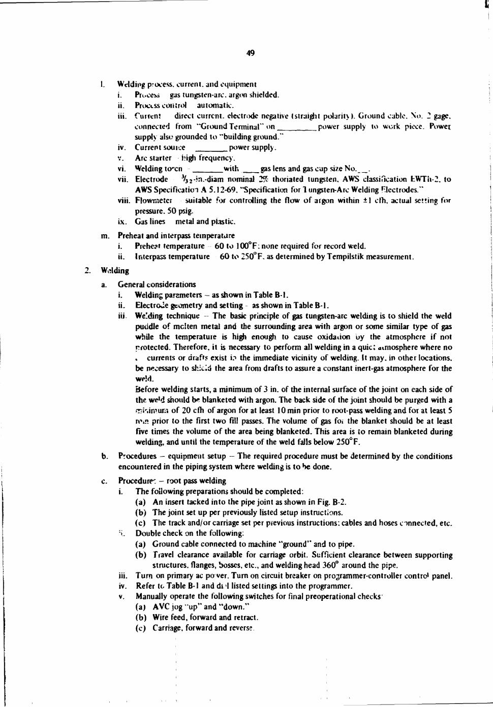
49
1. Welding process, current, and equipment i. Pre»ce:>s gas tungsten-arc. argon shielded. ii. Process control automatic. iii. Current direct current, electrode negative (straight polarity). Ground cable. No. 2 gage,
connected from "Ground Terminal" on power supply to work piece. Power. supply also grounded to "building ground."
iv. Current source power supply. Arc starter high frequency.
vi. Welding to-cn with gas lens and gas cup size No. . vii. Electrode */32*-'n-'diam nominal 2% thoriated tungsten, AWS classification EWTh-2. to
AWS Specification A 5.12-69. "Specification for 1 ungsten-Arc Welding RIectrodes." viii. Flowmeter suitable for controlling the flow of argon within ±1 cfh, actual setting for
pressure. 50 psig. ix. Gas lines metal and plastic.
m. Preheat and interpass temperature i. Preheat temperature 60 to 100°F: none required for record weld. ii. Interpass temperature 60 to 250°F. as determined by Tempilstik measurement.
2. Wdding
a. General considerations i. Welding parameters - as shown in Table B-1. ii. Electrcue geometry and setting as shown in Table B-l. iii- Weeding technique -- The basic principle of gas tungsten-arc welding is to shield the weld
puddle of mclten metal and the surrounding area with argon or some similar type of gas while the temperature is high enough to cause oxidation uy the atmosphere if not protected. Therefore, it is necessary to perform all welding in a quici atmosphere where no .. currents or drafts exist i? the immediate vicinity of welding. It may, in other locations, be necessary to shield the area from drafts to assure a constant inert-gas atmosphere for the WPM.
Before welding starts, a minimum of 3 in. of the internal surface of the joint on each side of the we'd should be blanketed with argon. The back side of the joint should be purged with a »T-iriimum of 20 cfh of argon for at least 10 min prior to root-pass welding and for at least 5 Win prior to the first two fill passes. The volume of gas for the blanket should be at least five times the volume of the area being blanketed. This area is to remain blanketed during welding, and until the temperature of the weld falls below 250" F.
b. Procedures - equipment setup - The required procedure must be determined by the conditions encountered in the piping system where welding is to he done.
c. Procedure': - root pass welding i. The following preparations should be completed.
(a) An insert tacked into the pipe joint as shown in Fig. B-2. (b) The joint set up per previously listed setup instructions. (c) The track and/or carriage set per previous instructions: cables and hoses connected, etc.
:i. Double check on the following: (a) Ground cable connected to machine "ground" and to pipe. (b) Travel clearance available for carriage orbit. Sufficient clearance between supporting
structures, flanges, bosses, etc., and welding head 360° around the pipe. iii. Turn on primary ac po ver. Turn on circuit breaker on programmer-controller control panel. iv. Refer to Table B-l and di I listed settings into the programmer. v. Manually operate the following switches for final preoperational checks
(a) AVC jog "up" and "down." (b) Wire feed, forward and retract. (c) Carriage, forward and reverse
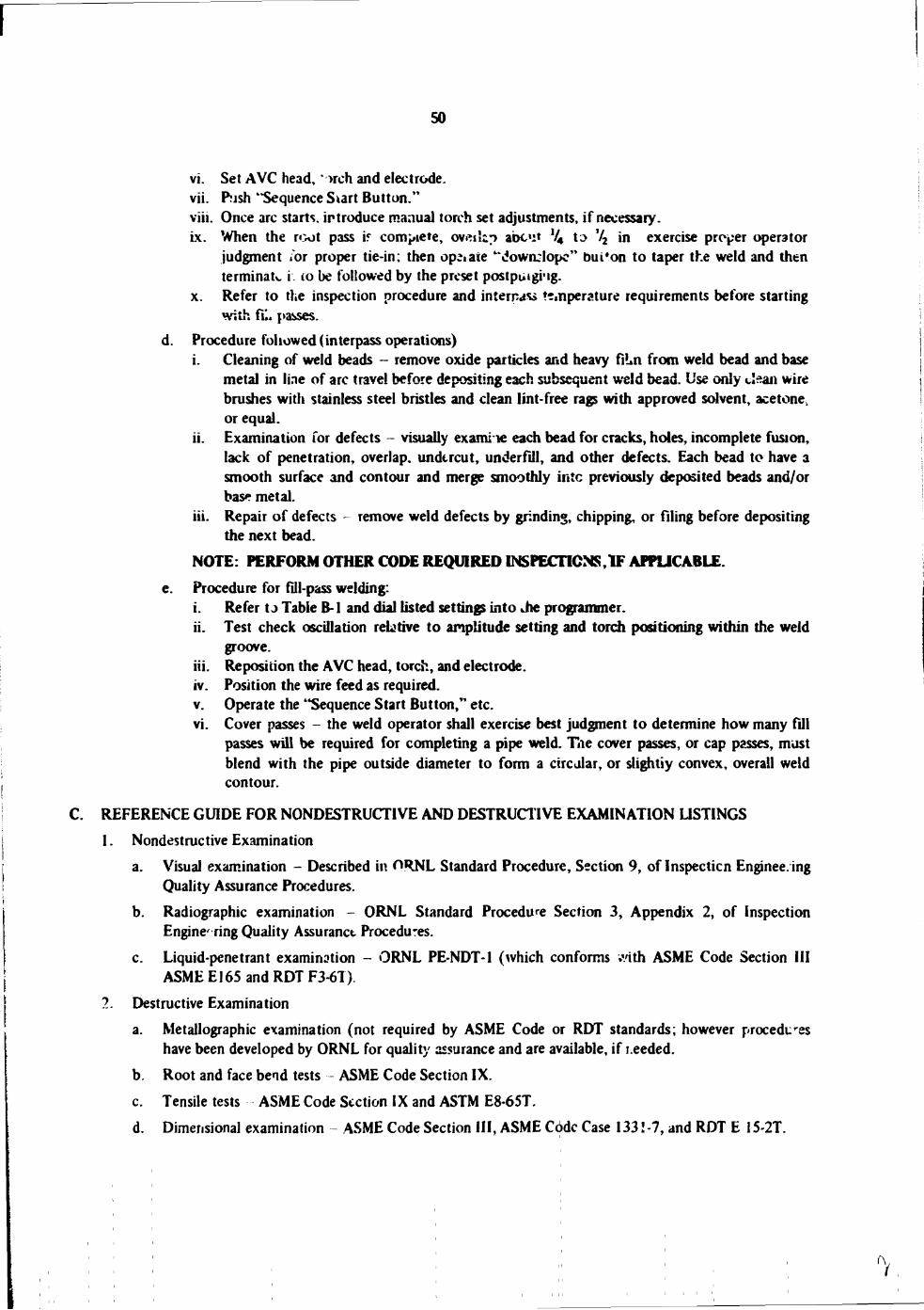
50
vi. Set AVC head, *>rch and electrode. vii. Push "Sequence Siart Button." viii. Once arc starts, introduce manual torch set adjustments, if necessary. ix. When the root pass if complete, ov«ilip abc«i» lU to V2 in exercise proper operator
judgment /or proper tie-in; then opiate "dowrclopc" bui'on to taper the weld and then terminate i. to be followed by the preset postpuigi'ig.
x. Refer to the inspection procedure and interna** temperature requirements before starting with fE. passes.
d. Procedure followed (interpass operations) i. Cleaning of weld beads - remove oxide particles and heavy fiUn from weld bead and base
metal in line of arc travel before depositing each subsequent weld bead. Use only dean wire brushes with stainless steel bristles and clean lint-free rags with approved solvent, acetone, or equal.
ii. Examination for defects - visually exami le each bead for cracks, holes, incomplete fusion, lack of penetration, overlap, undercut, underfill, and other defects. Each bead to have a smooth surface and contour and merge smoothly intc previously deposited beads and/or base metal.
iii. Repair of defects - remove weld defects by grinding, chipping, or filing before depositing the next bead.
NOTE: PERFORM OTHER CODE REQUIRED INSPECTIONS,IF APPLICABLE e. Procedure for fill-pass welding:
i. Refer t J Table B-1 and dial listed settings into Jie programmer. ii. Test check oscillation relative to amplitude setting and torch positioning within the weld
groove, iii. Reposition the AVC head, torch, and electrode, iv. Position the wire feed as required, v. Operate the "Sequence Start Button," etc. vi. Cover passes - the weld operator shall exercise best judgment to determine how many fill
passes will be required for completing a pipe weld. The cover passes, or cap passes, must blend with the pipe outside diameter to form a circular, or slightiy convex, overall weld contour.
REFERENCE GUIDE FOR NONDESTRUCTIVE AND DESTRUCTIVE EXAMINATION LISTINGS 1. Nondestructive Examination
a. Visual examination - Described in ORNL Standard Procedure, Section 9, of Inspection Enginee. ing Quality Assurance Procedures.
b. Radiographic examination - ORNL Standard Procedure Section 3, Appendix 2, of Inspection Engine ring Quality Assuranct Procedures.
c. Liquid-penetrant examination - ORNL PE-NDT-1 (which conforms with ASME Code Section III ASME El65 and RDT F3-6T).
2. Destructive Examination a. Metallographic examination (not required by ASME Code or RDT standards; however procedures
have been developed by ORNL for quality assurance and are available, if r.eeded. b. Root and face bend tests - ASME Code Section IX. c. Tensile tests ASME Code Section IX and ASTM E8-65T. d. Dimensional examination - ASME Code Section III, ASME Code Case 133! -7, and RDT E 15-2T.