the naroghid wind farm airservices australia proponent...
TRANSCRIPT
Page 1 of 13.
The Naroghid Wind Farm
Airservices Australia
Proponent : Naroghid Wind Farm Pty Ltd
AVIATION IMPACT STATEMENT
07 JUNE, 2017.

Naroghid Wind Farm
R. A. Gower MIEAust. Page 2 of 13.
1. Author's Name and Address
Richard Gower M.I.E. Aust.
72 – 74 Boundary Road,
Gruyere, Vic. 3770.
2. Qualifications and Experience.
Details of the author's qualifications and experience are given in Appendix 1.
3. Scope.
3.1 Instructions
The author's instructions from Wind Farm Developments Pty Ltd on behalf of Naroghid Wind
Farm Pty Ltd, the Proponent, were to prepare an aviation impact statement in response to the
criteria in AirServices Australia's outline document dated January, 2017.
4. Factual Information.
(a) The Naroghid wind farm was approved by the Minister of Planning in August, 2006. The
current work is directed to re-consenting for a decrease in the number of turbines from 22
to 12 and an increase in the tip height from 125m AGL to 180m AGL along with an
increase in blade radius of up to 70m and an allowable tower height of up to 110m AGL.
(b) As part of the Aviation Impact Statement preliminary work, the southernmost turbine
location has been deleted due to the combination of both its distance from the Cobden
aerodrome and from the runway 36 extended centre line.
(c) The number of turbines for the re-consenting planning application has therefore been
reduced from 13 to 12 as a result of the risk assessment for aviation.
Naroghid Wind Farm
R. A. Gower MIEAust. Page 3 of 13.
5. Response to AIS Criteria.
5.1 Airspace Procedures.
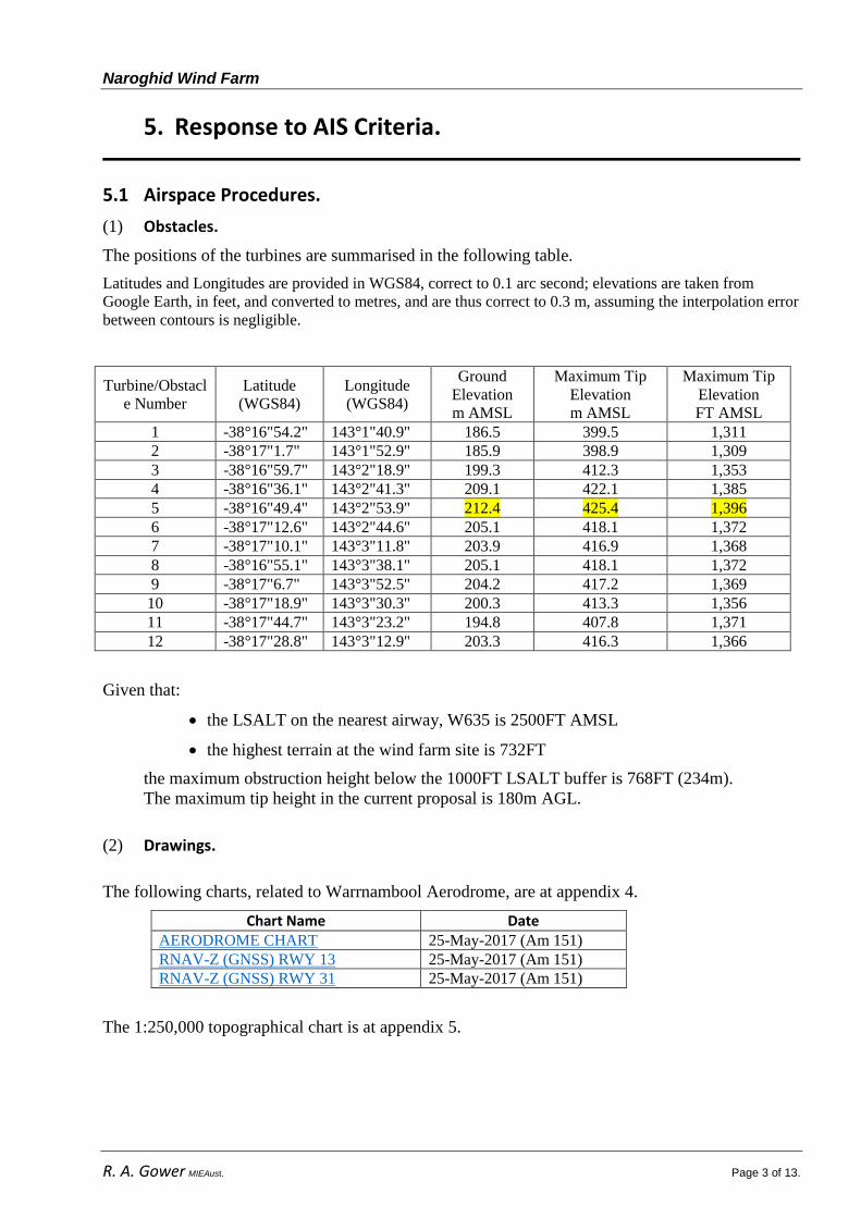
(1) Obstacles.
The positions of the turbines are summarised in the following table.
Latitudes and Longitudes are provided in WGS84, correct to 0.1 arc second; elevations are taken from
Google Earth, in feet, and converted to metres, and are thus correct to 0.3 m, assuming the interpolation error
between contours is negligible.
Turbine/Obstacl
e Number
Latitude
(WGS84)
Longitude
(WGS84)
Ground
Elevation
m AMSL
Maximum Tip
Elevation
m AMSL
Maximum Tip
Elevation
FT AMSL
1 -38°16"54.2" 143°1"40.9" 186.5 399.5 1,311
2 -38°17"1.7" 143°1"52.9" 185.9 398.9 1,309
3 -38°16"59.7" 143°2"18.9" 199.3 412.3 1,353
4 -38°16"36.1" 143°2"41.3" 209.1 422.1 1,385
5 -38°16"49.4" 143°2"53.9" 212.4 425.4 1,396
6 -38°17"12.6" 143°2"44.6" 205.1 418.1 1,372
7 -38°17"10.1" 143°3"11.8" 203.9 416.9 1,368
8 -38°16"55.1" 143°3"38.1" 205.1 418.1 1,372
9 -38°17"6.7" 143°3"52.5" 204.2 417.2 1,369
10 -38°17"18.9" 143°3"30.3" 200.3 413.3 1,356
11 -38°17"44.7" 143°3"23.2" 194.8 407.8 1,371
12 -38°17"28.8" 143°3"12.9" 203.3 416.3 1,366
Given that:
the LSALT on the nearest airway, W635 is 2500FT AMSL
the highest terrain at the wind farm site is 732FT
the maximum obstruction height below the 1000FT LSALT buffer is 768FT (234m).
The maximum tip height in the current proposal is 180m AGL.
(2) Drawings.
The following charts, related to Warrnambool Aerodrome, are at appendix 4.
Chart Name Date AERODROME CHART 25-May-2017 (Am 151)
RNAV-Z (GNSS) RWY 13 25-May-2017 (Am 151)
RNAV-Z (GNSS) RWY 31 25-May-2017 (Am 151)
The 1:250,000 topographical chart is at appendix 5.
Naroghid Wind Farm
R. A. Gower MIEAust. Page 4 of 13.
(3) Aerodromes.
The following aerodromes are located within 30NM of the proposed wind farm:
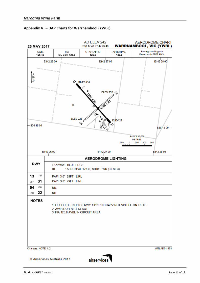
(a) Warrnambool Aerodrome (YWBL) is registered and has a 1372m bitumen runway
aligned 13/31 and a 1069 gravel runway aligned 04/22. It is located 27NM from the site
and is therefore outside the 25NM MSA radius. It does however lie within the 30NM
radius from YWBL ARP.
No obstacle associated with the proposal would penetrate the OLS for YWBL.
There are six (6) towers in the general vicinity as published in ERSA. These include a
549FT unlit tower, at 4NM SW of the aerodrome and a 394FT unlit tower 2.8NM to the
NNE.
(b) Cobden Aerodrome (YCDE) is uncertified and has a 900m bitumen runway 15m wide
aligned 18/36. The RWY 18 threshold is located 2.63 km (1.4NM) from the nearest
proposed wind turbine (#11).
There is no OLS applicable to this aerodrome.
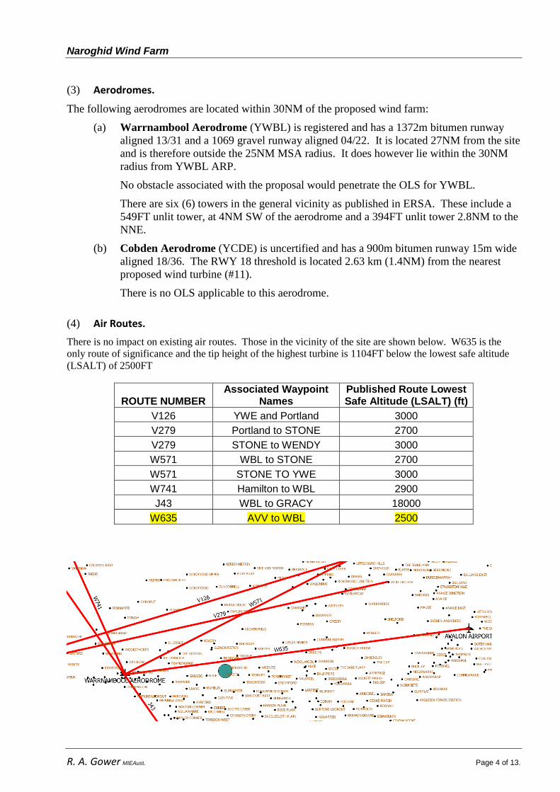
(4) Air Routes.
There is no impact on existing air routes. Those in the vicinity of the site are shown below. W635 is the
only route of significance and the tip height of the highest turbine is 1104FT below the lowest safe altitude
(LSALT) of 2500FT
ROUTE NUMBER Associated Waypoint
Names Published Route Lowest Safe Altitude (LSALT) (ft)
V126 YWE and Portland 3000
V279 Portland to STONE 2700
V279 STONE to WENDY 3000
W571 WBL to STONE 2700
W571 STONE TO YWE 3000
W741 Hamilton to WBL 2900
J43 WBL to GRACY 18000
W635 AVV to WBL 2500
Naroghid Wind Farm
R. A. Gower MIEAust. Page 5 of 13.
(5) Airspace.
The proposed site is contained wholly within G airspace.
5.2 Navigation/Radar.
By calculation, the proposed wind farm is significantly beyond the theoretical radar horizon from
both the Mt Macedon and Gellibrand Hill sites.
The calculated figures are shown in the table below and are derived from the formula:
D = K√(h1–h2)
where K = 1.23i
D is the distance to the radar horizon in NM and
h1 and h2 are the transmitter and target heights in FT AMSL.
The formula is quoted extensively in ICAO Guidance Material on Surveillanceii and also in
Introduction to Radar Systems – Skolnickiii
The maximum tip height of 1,396FT AMSL (turbine #5) is used in calculating the following:
Site Site Elevation Distance –
Site to Wind Farm Radar Horizon
Gellibrand Hill Primary Radar
<222 m AHD 729FT AMSL
174 km 94NM
31NM
Gellibrand Hill Secondary Radar
<222 m AHD 729FT AMSL
174 km 94NM
31NM
Mt Macedon Secondary Radar
1043 m AHD 3422FT AMSL
166 km 90NM
55NM
(1) Dead zones.
No probability due to the distance of the site beyond the radar horizon.
(2) False Target Analysis.
No probability due to the distance of the site beyond the radar horizon.
(3) Target Positional Accuracy.
Not applicable.
(4) Probability of Detection.
Not applicable.
(5) Radar Coverage Implications.
No known implications.

Naroghid Wind Farm
R. A. Gower MIEAust. Page 6 of 13.
6. Declaration.
I have made all the inquiries that I believe are desirable and appropriate and no
matters of significance which I regard as relevant have, to my knowledge, been
omitted.
Signed
07 June, 2017.

Naroghid Wind Farm
R. A. Gower MIEAust. Page 7 of 13.
7. Appendices.
Appendix 1 - QUALIFICATIONS AND EXPERIENCE OF THE AUTHOR.
Engineering
The author holds electrical and electronic engineering qualifications appropriate to the grade
of member of the Institution of Engineers Australia.
Engineering experience includes:
over 55 years technical support experience on aircraft avionics, electrical, fuel and
hydraulic systems on piston, turboprop and jet transport aircraft.
over 35 years experience as an aircraft design signatory under CAR Reg. 40/41 and
CAR 35/36 both as an individual and on behalf of Ansett Airlines and Ansett
Engineering Services.
Operational.
The author has 57 years of flying experience and has logged 11,000 flying hours and holds a:
commercial pilots licence (multi-engine, land and sea)
Grade 1 (A grade) flight instructor rating,
CASA Flight Examiner approval.
RFACA Master Instructor Certificate.
flight instructor training approval.
low-level aerobatic approval.
instructor training approval in aerobatics and formation flying.
Operational and airspace experience includes:
Chief Pilot and Chief Flying Instructor of Royal Victorian Aero Club, Coldstream
Flying School and Yarra Valley Flight Training.
Industry Convenor of the Victorian Regional Airspace and Procedures Advisory
Committee (RAPAC) for six (6) years and a member for 37 years.
In 2006, under contract to CASA, revised and reorganised the layout of the CASA
VHF Flight Guide.
Contact details:
tel 0418 358 250
fax (03) 9739 0121
email [email protected]
Naroghid Wind Farm
R. A. Gower MIEAust. Page 8 of 13.
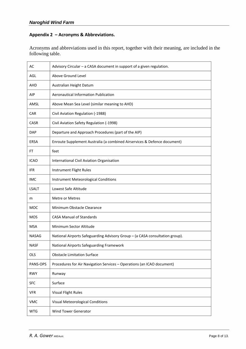
Appendix 2 – Acronyms & Abbreviations.
Acronyms and abbreviations used in this report, together with their meaning, are included in the
following table.
AC Advisory Circular – a CASA document in support of a given regulation.
AGL Above Ground Level
AHD Australian Height Datum
AIP Aeronautical Information Publication
AMSL Above Mean Sea Level (similar meaning to AHD)
CAR Civil Aviation Regulation (-1988)
CASR Civil Aviation Safety Regulation (-1998)
DAP Departure and Approach Procedures (part of the AIP)
ERSA Enroute Supplement Australia (a combined Airservices & Defence document)
FT feet
ICAO International Civil Aviation Organisation
IFR Instrument Flight Rules
IMC Instrument Meteorological Conditions
LSALT Lowest Safe Altitude
m Metre or Metres
MOC Minimum Obstacle Clearance
MOS CASA Manual of Standards
MSA Minimum Sector Altitude
NASAG National Airports Safeguarding Advisory Group – (a CASA consultation group).
NASF National Airports Safeguarding Framework
OLS Obstacle Limitation Surface
PANS-OPS Procedures for Air Navigation Services – Operations (an ICAO document)
RWY Runway
SFC Surface
VFR Visual Flight Rules
VMC Visual Meteorological Conditions
WTG Wind Tower Generator
Naroghid Wind Farm
R. A. Gower MIEAust. Page 9 of 13.
Appendix 3 – Calculation of Radar Horizon From Terrain Data.
The following is a calculation of the radar horizon based on the topography. It does
not consider radar energy diffraction due to atmosphere influence but does however
consider the height of the intermediate terrain.
Airservices Australia have provided locations and elevations of the relevant primary and secondary radars.
Publically available mapping software (Google Earth, and Geoscience Australia’s ELVIS) have been used to
assess whether the proposed wind farm has any line of sight contact with those radars.
The first assessment required according to the EURO Guidelines is reproduced below:
The first assessment that shall take place is to determine whether or not any part of the
turbine will be within the line of sight of the radar (i.e. from the electrical centre of the
radar antenna). If the turbines are located in a way that does not affect the surveillance
sensor performance (e.g. the turbines are fully ‘hidden’ from the sensors by terrain or
the turbines are located further away than the radar instrumented range), then consent
for the development can be approved. However if a part of the wind turbine (e.g. a
blade) can be in radar line of sight then there is potential for an impact upon the radar.
This assessment indicates that terrain intercepts the path at approximately 50NMl. The following is a
trigonometric, line of sight analysis based on a turbine tip height of 234m on the highest point of terrain on
the site.
The line of sight assessment considers both the Earth’s curvature but not any additional range due to
atmospheric refraction as does the formula quoted in 5.2 above. It does however consider height of
intermediate terrain between the radar sites and the wind farm.
The following calculations indicate that the proposed wind turbines would be not visible to the radars at
Gellibrand Hill or Mt Macedon.
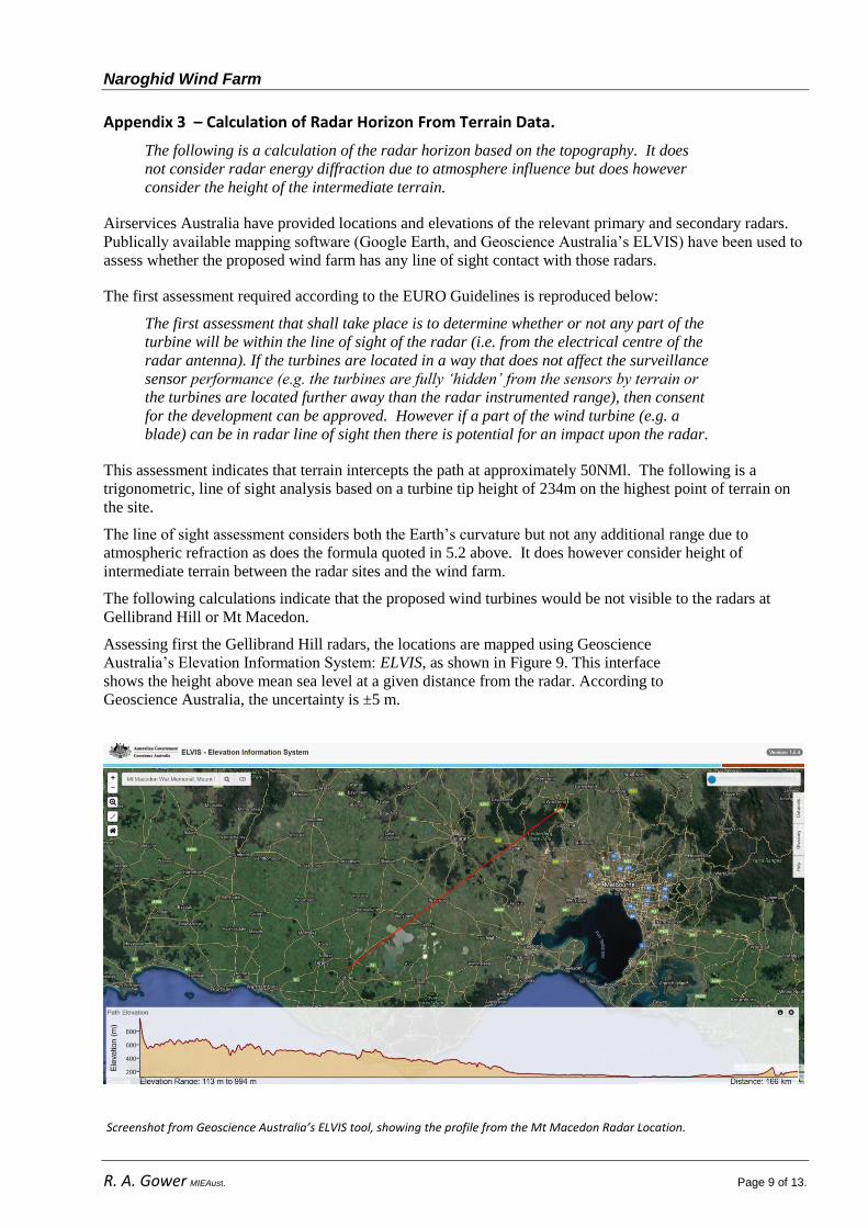
Assessing first the Gellibrand Hill radars, the locations are mapped using Geoscience
Australia’s Elevation Information System: ELVIS, as shown in Figure 9. This interface
shows the height above mean sea level at a given distance from the radar. According to
Geoscience Australia, the uncertainty is ±5 m.
Screenshot from Geoscience Australia’s ELVIS tool, showing the profile from the Mt Macedon Radar Location.
Naroghid Wind Farm
R. A. Gower MIEAust. Page 10 of 13.
The Earth’s curvature can be accounted for by considering the Earth as a circle with radius, r, 6371 km.
Thus, setting the radar as the origin, in two-dimensional Cartesian co-ordinates, the effect of the Earth’s
curvature is given by the equation of a circle, where x is the distance co-ordinate, and y is the height co-
ordinate, each given in kilometres:
Then, the terrain height above mean sea level at a distance x from the origin is y’. Thus the
effective height can be mapped with respect to the Earth’s curvature such that:
However, the map length from the Radar location R to the Wind Farm location W, is based on mean sea
level, and thus refers to an arc length. The arc length is thus known, allowing the arc angle to be computed,
and related back to the Cartesian x co-ordinate as follows:
|
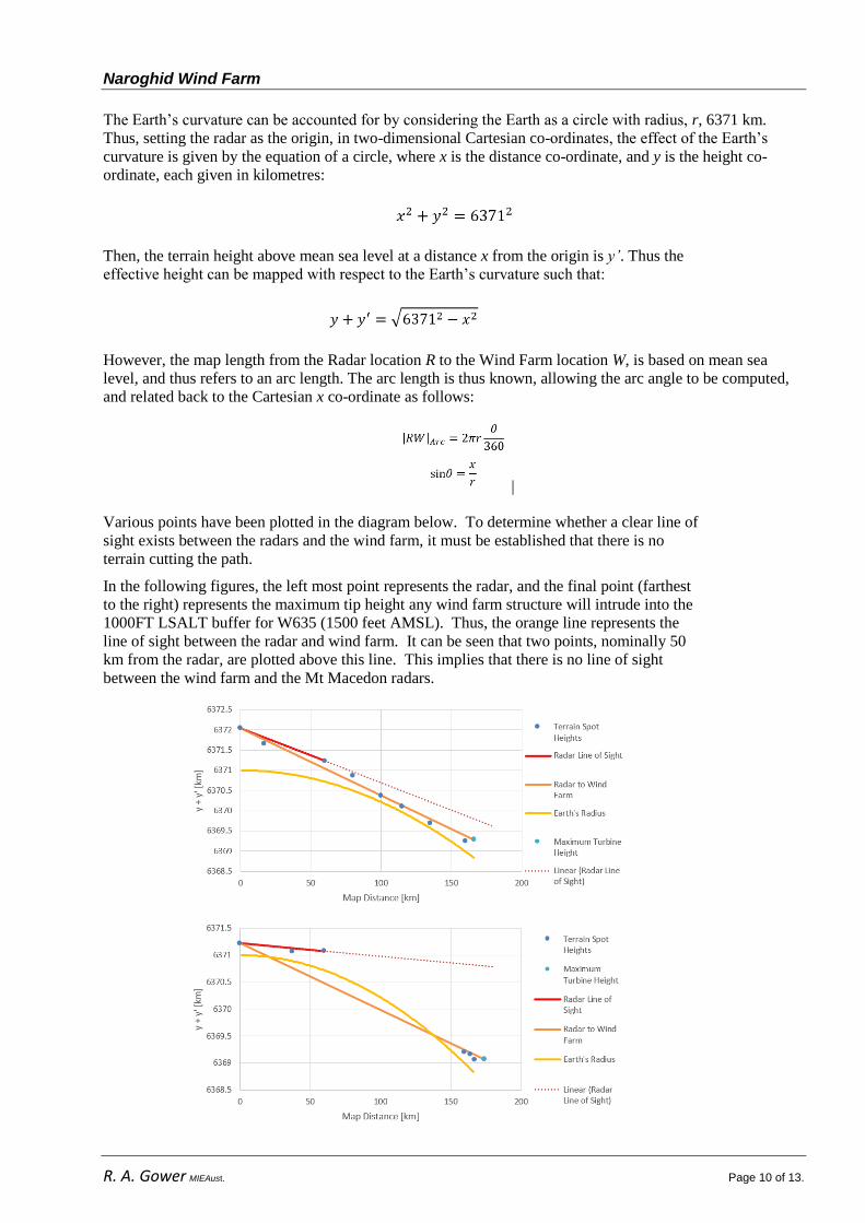
Various points have been plotted in the diagram below. To determine whether a clear line of
sight exists between the radars and the wind farm, it must be established that there is no
terrain cutting the path.
In the following figures, the left most point represents the radar, and the final point (farthest
to the right) represents the maximum tip height any wind farm structure will intrude into the
1000FT LSALT buffer for W635 (1500 feet AMSL). Thus, the orange line represents the
line of sight between the radar and wind farm. It can be seen that two points, nominally 50
km from the radar, are plotted above this line. This implies that there is no line of sight
between the wind farm and the Mt Macedon radars.
Naroghid Wind Farm
R. A. Gower MIEAust. Page 11 of 13.
Appendix 4 – DAP Charts for Warrnambool (YWBL).

Naroghid Wind Farm
R. A. Gower MIEAust. Page 12 of 13.
Naroghid Wind Farm
R. A. Gower MIEAust. Page 13 of 13.
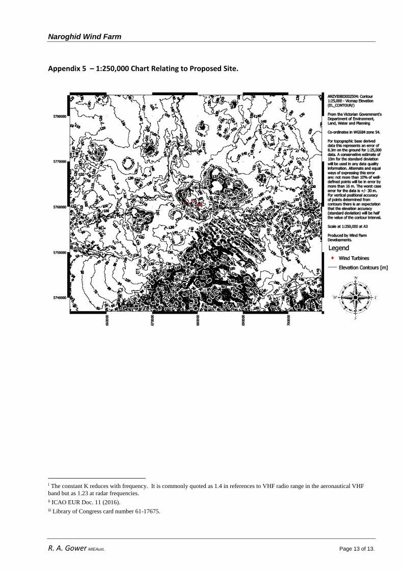
Appendix 5 – 1:250,000 Chart Relating to Proposed Site.
i The constant K reduces with frequency. It is commonly quoted as 1.4 in references to VHF radio range in the aeronautical VHF
band but as 1.23 at radar frequencies.
ii ICAO EUR Doc. 11 (2016).
iii Library of Congress card number 61-17675.