the motion interactive medical exercise robot...
TRANSCRIPT

1 | P a g e
The Motion Interactive Medical Exercise Robot
(M.I.M.E.R.)
Collaborative Project between Anschutz Medical Center and
Colorado State University
Completed Works By:
Salem Al-Aqeel – Electrical Engineer
John Allison – Mechanical Engineer
Trevor Pier – Mechanical Engineer
Jay Vickers – Computer Engineer
Lucas Wadman – Electrical Engineer
Daniel White – Electrical Engineer
Project Advisors: Sudeep Pasricha, Anthony Maciejewski
Approved by: ________Sudeep Pasricha_______________

2 | P a g e
Executive Summary
The Mirror Neuron System (MNS) in every human being is crucial for development. This
system allows people to take in auditory or ocular cues to make a decision or to complete a task.
Sometimes this system is not fully developed, but this can be alleviated through repetitive
movements and practice using the MNS. Exercising the MNS not only helps with physical motor
development, but with cognitive processes as well. Mirror neuron units are thought to be
involved with the ability to imitate and learn from other’s actions and understand intentions from
body language [1].
Devices exist that utilize motion and visual cues for therapy, rehabilitation, and
development of the MNS. Robots have been developed by other institutions that have
functionality of mirroring such as the Bandit from USC and the NAO by Aldebaran Robotics.
Physical therapy is widely used for children with underdeveloped MNS, but since this requires
one on one attention it can be expensive. If some of this time could be spent with Motion
Interactive Medical Exercise Robot (MIMER), it could cut costs and resources used. MIMER
will allow a child to practice these motions to develop their MNS.
This project’s goal is to produce MIMER, which mimics and encourages movement of
underdeveloped children. The main purpose of this device is to provide therapy for the clients to
gain basic motor and neuronal function. The first hurdle in designing a robot that can mirror
motion is to select a motion sensing device. The Kinect sensor created by Microsoft provides a
software development kit that encourages developers to use the Kinect. Using infrared, the
sensor can calculate distances for 20 joints in the body and is currently one of the most advanced
motion sensing devices on the consumer market.
Distances in three dimensions are output by the Kinect sensor so that the client’s arm
position can be known. However, this data will not operate motors so the signal must be
manipulated by using an algorithm on a laptop that uses trigonometry to change the distances
into angles for the servo motor to turn. These angles are fed to the servo motors through pulse
width modulation.
Pulse width modulation is accomplished using a Pololu servo controller that allows for
the adjustment of speed and acceleration in the motors. The code from the laptop gives a signal
that provides an associated pin number, acceleration, speed, and motor position. Once the servo
controller has the information it can operate multiple motors at the same time. Many
microcontroller combinations were tested but none compared to the speed of the Pololu and
laptop combination.
Creating the arms for the robot took some extensive research and testing into motors and
finding the degrees of freedom for the joints of the arms. Once the motor number, type and
position were determined, mounting the motors became a hurdle. Lynxmotion makes servo
brackets that are inexpensive, easy to assemble, and disassemble. After some calculations and
testing the arms were made shorter and the motors were switched out to optimize torque and
reduce weight as well as current draw.

3 | P a g e
Although the original Kinect sensor does not track finger motion, hands were created in
hopes of adding the newest Kinect sensor or using a webcam by later groups that can track hand
motion. Robot hands could also be hard coded to play games that the client could mimic. Hands
were designed with three fingers rather than five to reduce weight and current draw. This would
also better resemble the hands of most stuffed animals. The fingers, made from bicycle chain, are
operated by small servo motors with stiff linkages that can flex with the finger but are stiff
enough to push the finger back open. The palms that house the motors and fingers were designed
in CAD and 3D printed.
For the robot body, parts were designed and 3D printed in plastic. A torso consisting of
three parts houses the electronics and supports the arms. 3D printing allows for the freedom to
alter the size, shape and function of the parts. The body is covered in a stuffed animal monkey
skin that was purchased and gutted. The monkey is attractive to children and it has fingers that
work well with the mechanical fingers. The robot is supported in the back by a 3D printed slat
that allows for removal from the support box. A support box was created as an anchor for the
robot during motion as well as to house the Kinect sensor and battery.
The power circuit uses a PMOS that allows for battery power and wall power switching.
The battery is 14 amp-hours and the system could pull 6 amps maximum with an average of 2-3
amps during normal operation. The Kinect sensor receives 12 volts while the motors and fans
require 5 volts. A custom made PCB was made to provide power and ground to all of the motors.
The objectives met in creating the robot were a quick reaction speed, small size, 10
degrees of freedom, autonomous, and attractive. Original budget goals were not met. However,
the project had extra support that allowed for a budget up to $2050 that was met.
Motion Interactive Medical Exercise Robot (MIMER) has been a great success due to its
operation and functionality. All of the sponsor’s goals were met with many bonus extras. Future
teams could add finger tracking with the new Kinect sensor just released. Other additions could
include speech recognition and more motors for more lifelike motion. MIMER is an important
step in social robotics that has a vital use in the medical field of physical therapy. The future is
bright for MIMER.

4 | P a g e
Table of Contents
Executive Summary ...................................................................................................................................... 2
List of Tables ................................................................................................................................................ 5
List of Figures ............................................................................................................................................... 5
Introduction and Background ....................................................................................................................... 7
Objectives and Constraints ........................................................................................................................... 7
Design Summary ........................................................................................................................................... 8
Fall Semester 2014 Work ............................................................................................................................ 11
Chapter 1 – Xbox Kinect Sensor ................................................................................................................ 11
Chapter 2 – Computer Computation ........................................................................................................... 12
Chapter 3 – Microcontrollers and Motors ................................................................................................... 14
Chapter 4 – Mechanical Design .................................................................................................................. 15
Design Decisions .................................................................................................................................... 15
Detail Design and Supporting Analysis .................................................................................................. 17
Safety and Ethical Considerations .......................................................................................................... 21
Chapter 5 – Power Circuit ........................................................................................................................... 21
Objectives and constraints of the power circuit ...................................................................................... 21
Advantages of chosen power circuit ....................................................................................................... 22
Final design ............................................................................................................................................. 22
Issues and solutions ................................................................................................................................. 26
Progress through the year ........................................................................................................................ 27
Ethical considerations ............................................................................................................................. 28
Conclusions and Future Work..................................................................................................................... 28
References ................................................................................................................................................... 30
Appendix A - Acronyms ............................................................................................................................. 31
Appendix B – Budget .................................................................................................................................. 32
Appendix C – Timelines ............................................................................................................................. 33
Timeline updated 1-8-14 ......................................................................................................................... 33
Timeline updated 1-23-14 ....................................................................................................................... 37
Timeline updated 2-9-14 ......................................................................................................................... 41
Timeline updated 4-24-14 ....................................................................................................................... 45
Appendix D – Funding Documents ............................................................................................................ 50

5 | P a g e
What is this project? ................................................................................................................................ 50
So…what do you need? .......................................................................................................................... 50
How will this benefit «Company_Name»? ............................................................................................. 51
Appendix E – Thank You Letter – Agilent ................................................................................................. 52
Appendix F – Previous Circuit Layouts ...................................................................................................... 53
Appendix G – Mechanical Results.............................................................................................................. 55
Acknowledgements ..................................................................................................................................... 58
List of Tables
Table 1: Constraints (Priority Levels on a 1-10 Scale - 10 Being the Most Important) ............................... 7
Table 2: Pugh Analysis to Determine Motor Type ..................................................................................... 16
Table 3: Pugh Analysis to Determine Arm Construction ........................................................................... 16
Table 4: Pugh Analysis of Torso Design .................................................................................................... 16
Table 5: Pugh Analysis of Robot Skin Selection ........................................................................................ 17
Table 6: MIMER Power Circuit Constraints with an Impact on Circuit Design ........................................ 22
Table 7: Different Voltage Requirements by Component in the MIMER System ..................................... 22
Table 8: The MIMER Power System Component Overview ..................................................................... 23
Table 9: Budget ........................................................................................................................................... 32
Table 10: Torque Calculations with a Potential Hand Attached ................................................................. 57
List of Figures
Figure 1: Final Design .................................................................................................................................. 9
Figure 2: Servo and Bracket Skeleton Assembly .......................................................................................... 9
Figure 3: Kinect for Windows .................................................................................................................... 10
Figure 4: Pololu Servo Controller ............................................................................................................... 10
Figure 5: Aesthetic Components ................................................................................................................. 10
Figure 6: Joint Tracking for Xbox Kinect [4] ............................................................................................. 12
Figure 7: First Arm Completed Compared to Second Arm ........................................................................ 17
Figure 8: Shoulder, Elbow, Finger Motor Size Comparison ...................................................................... 18
Figure 9: Progression of Hand Design ........................................................................................................ 19
Figure 10: Torso CAD Model ..................................................................................................................... 19
Figure 11: CAD Models of Circuit Board Boxes ....................................................................................... 20
Figure 12: Skeleton View of Finished Robot .............................................................................................. 20
Figure 13: Finished Robot with Monkey Skin Attached ............................................................................ 21
Figure 14: MIMER Power Flow Chart ....................................................................................................... 23
Figure 15: Switch PCB Circuit Schematic .................................................................................................. 24

6 | P a g e
Figure 16: PCB Mounting Box ................................................................................................................... 24
Figure 17: Distribution Power Circuit ........................................................................................................ 25
Figure 18: Distribution PCB Layout ........................................................................................................... 26
Figure 19: Previous Circuit Layout ............................................................................................................. 53
Figure 20: Circuit Layout 1 ......................................................................................................................... 53
Figure 21: Circuit Layout 2 ......................................................................................................................... 54
Figure 22: Current vs. Torque at Different Voltages on HS-422 Servo ..................................................... 55
Figure 23: Motor Specifications ................................................................................................................. 55
Figure 24: Torque Calculations without Hand ............................................................................................ 56
Figure 25: Potential Length of Arm with Hand Attached ........................................................................... 56

7 | P a g e
Introduction and Background
This project’s goal is to produce a device that mimics and encourages movement of
underdeveloped children. The main purpose of this device is to provide therapy for the clients to
gain basic motor and neuronal function through use of this device. The Anschutz medical center
at the University of Colorado Denver has determined this need from observing positive results
from a child with Autism using a similar device.
There is some biological theory behind why a robot that mimics movements would help
with development. Studies have been done that determined the existence of Mirror Neuron Units
in humans, which are functional neuronal units that connect the observation of a movement with
its execution. “Exercising” these units not only helps with physical motor development, but with
cognitive processes as well.
Devices currently exist that use motion and visual cues for therapy and rehabilitation
including. Physical therapy is widely used for underdeveloped kids, however since this requires
one on one attention, such therapy can be expensive. Costs can be cut if therapy is conducted
with the robot in place of a full-time Physical Therapist.
Objectives and Constraints
It has been determined that in order to meet the needs of the sponsors and their clients we
need to meet certain constraints. The main objectives of the final product where provided by our
sponsor from Anschutz Medical Center. Below are the constraints set at the beginning of the
project and details on how each was accomplished.
Table 1: Constraints (Priority Levels on a 1-10 Scale - 10 Being the Most Important)
Objective Priority Method of
Measure
Objective
Direction
Target
Cost 8 USD Minimize < $ 1,500
Size 9 Height (in) Minimize < 24 in.
React. Speed 10 Time (ms) Minimize < 1,500 ms
Movement 10 DOF Maximize ≥ 4 DOF/arm
Weight 8 lbs Minimize < 1 lb/per arm
Autonomy 8 # Interventions Minimize < 2/session
Attractive 10 Time (min) Maximize Holds attention of 50% of
children >10mins
Cost: The above cost does not include the addition of the laptop in the final design. The laptop
was determined necessary to improve reaction speed.

8 | P a g e
Size: The size of the robot body was determined to be the size of an average stuffed animal so
the device would not be imposing, but still is easily intractable with clear movements. This was
accomplished by keeping the size of the robot close but less than 24 inches.
Reaction Speed: This was one of the most important aspects of the device, as the reaction speed
determines the effectiveness. Many systems were tested, but cost and the ability to be a closed
system was sacrificed to include a laptop for processing. This brought the reaction speed to
consistently 500 ms, well below our constraint.
Movement: To be able to do all natural arm movements, four DOFs per arm were determined to
be needed. The necessary movements are rotation and extension of both shoulders and elbows.
The final design exceeded this goal by including these, and adding three fingers per arm. While
the current Kinect cannot sense fingers, this capability can be added with later technology.
Movement of fingers is accomplished currently through a scripted program, which adds to
interaction with the device.
Weight: The weight of the arms was an important criterion as the motors needed to be able to
handle all movements while remaining structurally intact. This was accomplished through use of
the lightest motors and brackets possible in the arms.
Autonomy: The device should be easy to use. When set up, the device only needs input from the
user interface on the laptop to execute or stop. While running the device proved to require less
than one intervention on average to adjust a component.
Attractiveness: The end goal was to provide an engaging interactive device to provide useful
therapy. While hard testing is still yet to be scheduled with our sponsor’s clients, the device
consistently attracted patron, including high school students at the E-days presentation. Further
testing in a clinical setting is desired.
Design Summary
Overview: For a simple overview, the mimicking robot will sit on top of a small shelf that will
hold the electronics and put the robot at a height that would be easy to interact with. The robot
itself is constructed of servo motors and specialized brackets which are attached and mounted on
the shelf using 3D printed parts. Input is received from a Microsoft Kinect sensor and is sent to a
laptop which calculates motors position. This information is sent to a Pololu servo motor
controller which then provides output to the motors. The device has an onboard battery, and two
custom power circuits including a printed circuit board that provides power to the motors,
internal fan, master switch and removable connections from the body to the box, and to wall
power if needed. The main components of the design are briefly described below.
Operation: The device was designed to be as easy to use as possible. The box and body are
easily transported as one piece. When ready to use, the USB cables to the motor controller and
Kinect will simply need to be plugged into the corresponding labeled ports on the laptop. From
here, the MIMER program in visual studio will be run, opening a convenient user interface with
prompts to Run, Stop, and debug information. A port on the left side can be connected for wall
power if necessary. For access to internal components, the box has a cabinet door that can be

9 | P a g e
opened, and the skin can be removed via Velcro. The body can also be removed by unplugging
the power and controller USB ports.
Servo Motors and Brackets: These will handle the motion for the arms. Testing has been done
with many servos and a number of Hi-Tec servo motors were selected for the final design. The
HS-85 has the highest torque rating and was implemented into each shoulder. The HS-85 motors
are smaller and provide less torque, making these motors suitable for the elbows. The HS-55
motors are the smallest available and used for the fingers. To assemble these into arms, the
Lynxmotion brand of brackets were used to construct a skeletal system.
Sensor: The Kinect for Windows was decided early on to be the sensor for detecting the
movements of the user. The reason to use this sensor instead of a webcam or similar device was
because the Kinect is able to sense depth as well as the basic x and y coordinates. Microsoft also
provides open source software development resources that assisted the programmers on this
project.
Figure 1: Final Design
Figure 2: Servo and Bracket Skeleton Assembly

10 | P a g e
Controller: A Pololu servo controller is
used to send signal to the servo motors
based on input from the laptop. It is
placed inside the robot body and is
connected to the laptop through USB.
Aesthetics: To store the electronics with a convenient stand for
the device, a simple cabinet was implemented. The cabinet
housing creates a professional look for the device and provides a
more contained system. To mount the arms, internal circuitry,
and provide structure to the body and hands, 3D printed parts
were created using CSU’s Idea 2 Product lab. As for the final
look of the body, a stuffed animal was purchased and
customized to fit the robot to give the device a kid-friendly
appeal.
Figure 5: Aesthetic Components
Figure 3: Kinect for Windows
Figure 4: Pololu Servo
Controller

11 | P a g e
Fall Semester 2014 Work
From a mechanical standpoint many tasks were completed at the end of the fall semester.
Structurally the focus was placed on the arms and motors due to the nature of the project.
Initially, the correct degrees of freedom were determined by making physical and CAD
(computer aided design) models to verify motor number, position, and orientation in the arms.
Secondly, the motor type and specifications had to be determined by testing several models of
motors. Once the selection of motors was narrowed down; power, speed and torque performance
had to be determined by measuring current draw, speed while adding load to motors, and testing
the endurance and torque. A prototype arm was built consisting of brackets and hardware
purchased from Lynxmotion. Lastly, the first concepts of the hand design were developed but not
built.
Additionally in the previous semester, the MIMER team worked mostly with the
RaspberryPi due to the possibility of meeting all our criteria theoretically (i.e. responding to the
user’s input in less than a second, being small enough to fit inside MIMER, and using Wi-Fi to
communicate). Last semester was focused on setting up the RaspberryPi to use and to implement
the software PWM signals. The team also spent a substantial amount of time trying to make the
RaspberryPi functional with Wi-Fi. Last semester was focused on the basic setup of the system,
and making sure the values were being sent correctly.
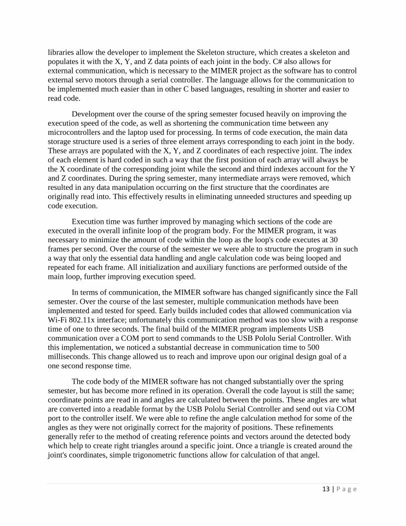
The MIMER program was written using the C# programming language in an effort to
adhere to the Kinect libraries provided by Microsoft for open source development. These
libraries allow the developer to implement the Skeleton structure, which creates a skeleton and
populates it with the X, Y, and Z data points of each joint in the body. C# also allows for
external communication, which is necessary for the MIMER project as the software has to
control external servo motors through a serial controller. The language allows for the
communication to be implemented much easier than in other C based languages, resulting in
shorter and easier to read code. At the end of the fall semester, we had compiled a basic program
to read in the data points and produce angles based upon joint position.
For the MIMER project, there were a number of accomplishments with the power
requirements and circuit design. Initial calculations for the required amounts of power in the
circuit were completed. Based off these calculations, a number of initial circuit designs were
created, which are shown in Appendix F. These different designs were tested for feasibility using
simplified versions of the circuits on a breadboard. This led our team to choose a power circuit
with parallel architecture; the team continued testing various aspects of that circuit. The previous
semester testing included fusing, switching between wall and battery power, and testing the DC-
DC converter central to the power distribution circuit.
Chapter 1 – Xbox Kinect Sensor
The Microsoft Kinect has been chosen as a sensing device for our project because it
meets our Electrical and Mechanical needs. “The Microsoft Kinect is currently the most
advanced motion sensing input device, and is easiest to use that is available to consumers”; it

12 | P a g e
enables users to interact and control the application or game without the need to touch an input
device. With a familiar user interface by using gestures and voice commands the application can
be controlled. Using an object recognizing approach, the Kinect can capture 3D body joint
positions, body shape, and body movement efficiently [2]. One of the Kinect’s onboard cameras
is an RGB camera that stores three-channel data in a 1280 x 960 resolution at 12 frames per
second (FPS), or a 640 x 480 resolution at 30 frames per second and a 320x240 16-bit depth
camera. The field of view (FOV) of the cameras are 57º horizontally and 43º vertically. It has a
tilt motor that can tile the both camera 27º vertically and a microphone array used for recognize
voice commands [3].
Figure 6: Joint Tracking for Xbox Kinect [4]
One of most important needs for the MIMER project is the ability to write code for the
motion sensor. The Kinect supports many different coding languages. Microsoft released a
Software Development Kit (SDK) to encourage developers to use the Kinect. This SDK was
meant to allow developers to write applications in C++/CLI, C#, or Visual Basic [5]. The SDK
also provides joint tracking libraries, which allow developers to obtain positional data related to
the user. This data is then processed through the main code body to produce the expected motor
outputs. The ease of obtaining positional data as well as a large field of view, high resolution,
and rapid refresh rate make the Kinect a great solution for the MIMER project.
Chapter 2 – Computer Computation
The programming aspect of the MIMER project is relatively simple in concept, but is
complex in application. The overall purpose of the code is to initialize the Kinect, read in raw X,
Y, and Z data points from the user, calculate the degrees required for each motor, and send this
data out to the Pololu servo controller. The MIMER application is structured as an infinite loop,
constantly reading in user data and sending out the processed data at 30 frames per second.
The MIMER program is written using the C# programming language in an effort to
adhere to the Kinect libraries provided by Microsoft for open source development. These
13 | P a g e
libraries allow the developer to implement the Skeleton structure, which creates a skeleton and
populates it with the X, Y, and Z data points of each joint in the body. C# also allows for
external communication, which is necessary to the MIMER project as the software has to control
external servo motors through a serial controller. The language allows for the communication to
be implemented much easier than in other C based languages, resulting in shorter and easier to
read code.
Development over the course of the spring semester focused heavily on improving the
execution speed of the code, as well as shortening the communication time between any
microcontrollers and the laptop used for processing. In terms of code execution, the main data
storage structure used is a series of three element arrays corresponding to each joint in the body.
These arrays are populated with the X, Y, and Z coordinates of each respective joint. The index
of each element is hard coded in such a way that the first position of each array will always be
the X coordinate of the corresponding joint while the second and third indexes account for the Y
and Z coordinates. During the spring semester, many intermediate arrays were removed, which
resulted in any data manipulation occurring on the first structure that the coordinates are
originally read into. This effectively results in eliminating unneeded structures and speeding up
code execution.
Execution time was further improved by managing which sections of the code are
executed in the overall infinite loop of the program body. For the MIMER program, it was
necessary to minimize the amount of code within the loop as the loop's code executes at 30
frames per second. Over the course of the semester we were able to structure the program in such
a way that only the essential data handling and angle calculation code was being looped and
repeated for each frame. All initialization and auxiliary functions are performed outside of the
main loop, further improving execution speed.
In terms of communication, the MIMER software has changed significantly since the Fall
semester. Over the course of the last semester, multiple communication methods have been
implemented and tested for speed. Early builds included codes that allowed communication via
Wi-Fi 802.11x interface; unfortunately this communication method was too slow with a response
time of one to three seconds. The final build of the MIMER program implements USB
communication over a COM port to send commands to the USB Pololu Serial Controller. With
this implementation, we noticed a substantial decrease in communication time to 500
milliseconds. This change allowed us to reach and improve upon our original design goal of a
one second response time.
The code body of the MIMER software has not changed substantially over the spring
semester, but has become more refined in its operation. Overall the code layout is still the same;
coordinate points are read in and angles are calculated between the points. These angles are what
are converted into a readable format by the USB Pololu Serial Controller and send out via COM
port to the controller itself. We were able to refine the angle calculation method for some of the
angles as they were not originally correct for the majority of positions. These refinements
generally refer to the method of creating reference points and vectors around the detected body
which help to create right triangles around a specific joint. Once a triangle is created around the
joint's coordinates, simple trigonometric functions allow for calculation of that angel.

14 | P a g e
Through the refinement of the angle calculation methods, as well as execution and
communication time improvements, we were able to reach many of our original design goals.
Response time was reduced to 500 milliseconds through the use of the Pololu Serial Servo
Controller, resulting in a more interactive system as the user is not waiting for MIMER to
respond to movements. Angle calculation was vastly improved and now provides more accurate
readings for each joint. This refinement results in a more accurate mirror system, and also
improves the user experience as the limb position of MIMER better reflect the position of the
user's limbs.
Chapter 3 – Microcontrollers and Motors
The Motion Interactive Medical Exercise Robot’s (M.I.M.E.R.) biggest challenge for the
team was the speed at which the robot had to respond to the users input. The initial goal for the
project was to have MIMER work over Wi-Fi with a response to the user’s input of less than one
second. The team was not able to get MIMER to respond to user’s input in less than one second
over Wi-Fi. Once we eliminated this constraint the MIMER team selected a Pololu USB Serial
Servo Controller. The system design from sending information from the Xbox Kinect to a
computer and out to the serial servo controller allowed MIMER to respond to users input in less
than a second.
In order to arrive at the decision to use the Pololu Serial Servo Controller, the MIMER
team first used what they were familiar with. The project first started out on a RaspberryPi in
order to meet the Wi-Fi constraint of the project. The servos were being controlled using C# and
with software pulse width modulation (PWM). At the time this was the cheapest route to go to a
theoretical solution meeting all of our design constraints. The first problem to evidence itself
within the MIMER system was the non-scalable software PWM generation. The team created a
delay (with a “ticking” function) on the RaspberryPi to generate the pulses to control the servos.
This worked for about 3-4 motors; a long way from 16. This led us to the Pololu Serial Servo
Controller (Non-USB and controlled from the Raspberry Pi; Serial Servo Controller ROB-
08897) [6].
The MIMER team struggled with the Pololu Serial Servo Controller; this was due to a
common ground issue being overlooked for 3-4 weeks. This issue was not found until after the
team moved onto another device to solve their issues. The team moved on to the Arduino Mega,
before figuring out the issue (by this time the team felt they had spent too much time on the
Pololu with no results).
The Arduino Mega is a part of the Arduino network which contains a nice library to
control servo motors. This allowed the team to generate PWMs easily to control servos. At this
time the RaspberryPi was used for the Wi-Fi, and then the information was sent to the Arduino
via serial line. The team received that information from the RaspberryPi into a buffer. The
information was parsed and put into arrays to write out to the PWM pins. The problem the team
incurred with this system was after 15 iterations the information was incorrect. The information
coming in was not the same as the information “going out” of the RaspberryPi. At this time the
team believed the problem was with the RaspberryPi serial line due to the problem with the

15 | P a g e
Pololu Serial Servo Controller and the Arduino (the team did convert the 3.3v coming out of the
RaspberryPi to 5v for the Arduino and the Serial Servo Controller).
The team then purchased the Wi-Fi shield for the Arduino. This allowed the team to
finally test the speed at which information was being sent and received. This also allowed to
team to finally test the orientation of motors and the angles that were being computed. With this,
the system values were being sent and received and written to the motors in two to four seconds.
This was considerably slower than the team thought it would have been. This is when the team
realized the real time speed could not be achieved with Wi-Fi.
The team moved to connecting the computer to a hub to the RaspberryPi to the serial
servo controller. The RaspberryPi was chosen over the Arduino because of the faster processor
speed. This system was still too slow; the information was sent from the computer to the
RaspberryPi in one to two seconds. This does not include sending the information to the Pololu
Serial Servo Controller. The system was still too slow because the information had to go through
the network. In order to solve this problem the team thought to just send the information through
USB. This could be done with the Arduino.
The team implemented the USB to Arduino and out to the motors through the PWM pins
and also on a separate system with the serial servo controller on the Arduino. This was very
promising in that the motors were delayed by 800 milliseconds before putting the motors into an
arm configuration. Once the motors were put into the arm the motors speed slowed down
significantly to one to two seconds once again. The team then found the USB Pololu Controller
online.
The output of the program on the computer directly goes into a USB serial line into the
USB Serial Servo Controller. The speed for the output to the motors in the arm configuration is
now below one second. This is fast enough for a user to be engaged with the product, and to have
a good experience. Once this system was implemented the team was happy with the speed.
Chapter 4 – Mechanical Design
Design Decisions
The following Pugh analyses demonstrate design concepts that were considered and the
associated design objectives that were most important. Table 2 shows that the analog servo
would work best for the application needed. Current drain had a significant part in that decision.

16 | P a g e
Table 2: Pugh Analysis to Determine Motor Type
Design Objective Stepper Servo-Analog Servo-Digital
Speed 7 10 10
Acceleration 5 8 10
Position Control 6 9 10
Torque 8 9 10
Price (low) 10 8 5
Weight 4 10 9
Current Drain 6 8 5
Sum 46 62 59
Table 3 determines that Lynxmotion servo brackets would be the smartest selection for
arm construction. The ease of use including time to build distinguished the Lynxmotion
hardware from its competitors.
Table 3: Pugh Analysis to Determine Arm Construction
Design Objective Metal-Fab Plastic-Fab Lynxmotion
Durability 9 8 10
Time to build 5 6 10
Ease of Replication 6 8 10
Price (low) 8 10 9
Weight 7 10 9
Sum 35 42 48
Torso design was important to house the electronics and to carry the arms.
Table 4: Pugh Analysis of Torso Design
Design Objective 3D Printed
Plastic Aluminum
sheet metal Robot Shop
Torso
Price (low) 9 7 5
Weight 10 8 8
Functionality 10 9 7
Durability 7 9 9
Originality 10 8 6
Time to make 7 8 10
Easy to replicate 8 8 10
Sum 61 57 55

17 | P a g e
Three types of robot skins were considered that would be pleasing to a child and could
have moving fingers attached. Table 5 determines that a premade monkey would satisfy the
design objectives best. Premade stuffed monkeys tend to have longer fingers than most teddy
bears which are more favorable for visual clarity to the client.
Table 5: Pugh Analysis of Robot Skin Selection
Design Objective Premade
Teddy
Bear
Premade
Monkey Custom
made skin
Price (low) 9 9 5
Aesthetics 9 9 6
Functionality 7 8 9
Durability 8 8 7
Finger
Compatibility 8 10 10
Time to make 9 9 6
Easy to replicate 9 9 7
Sum 59 62 50
Detail Design and Supporting Analysis
Throughout motor testing and torque measurements it was discovered that the motors
were not able to lift an arm consistently with the torque rating provided by the supplier. Figure 7
shows the first prototype arm that is long and heavy. With thorough research, measurements, and
testing it was clear that the solution would need to be multipronged. Calculations can be found in
Appendix G. The solution included reducing the length of the arm, increasing the torque of the
shoulder motors, and reducing the size and weight of the elbow motors. The length of the second
arm compared to the first arm is displayed in Figure 7. The second arm is the final design.
Figure 7: First Arm Completed Compared to Second Arm

18 | P a g e
The motor size and weight decreases as it approaches the tip of the arm. This reduces the
torque on motors further up the arm towards the shoulder and in turn reduces the current draw
needed by those motors. Figure 8 demonstrates the size relations of the different motors.
Figure 8: Shoulder, Elbow, Finger Motor Size Comparison
Solving this torque issue reduced the current draw needed by the system and insured that
motors would not be overstressed which could have caused durability and overheating issues.
The selection of Lynxmotion brackets and hardware to mount the servo motors provided
arms that are easy to install and disassemble which is beneficial for repairs or alterations. These
brackets are easy to acquire for replication purposes as well.
Priorities of the sponsor focused on arm motion. However, the implementation of hands
would be a secondary benefit to this social robot. Finger design involved extensive research into
current designs. A concept was developed that considered low cost, simplicity, and durability.
Bicycle chain was chosen because it did not need to be manufactured, it is easy to replicate,
inexpensive and it is segmented with smooth pivoting action similar to a human finger. The
finger is pulled down by a tennis racquet string attached to a micro-servo motor. The string that
was chosen is very strong and flexible enough to bend with the finger yet stiff enough to push the
finger back open when the motor is reversed. Next, the palm that holds the motors and fingers
was modeled in CAD and 3D printed with extra plastic from the torso printings. Figure 9 shows
the progression of the hand design starting on the left with the first proof of concept to verify that
the motor and string could operate the bicycle chain like a real finger.

19 | P a g e
Figure 9: Progression of Hand Design
A torso was needed at the core of the robot to house electronics and wiring, support the
arms, and to hold a stuffed animal skin. CAD modeling and 3D printing the torso provided
freedom to alter the size, shape and function. The torso consists of a front, back and a support
slat in the back as shown in Figure 10. It has a front and back so that it can be opened to access
circuits and to install or remove shoulder motors. The front was designed with a hole for easy
quick access in case of repairs. The front and back are connected by small latches. The support
slat prevents the robot from rocking and swaying while the arms are in motion. The slat also lifts
the torso to make room for the stuffed monkey legs.
Figure 10: Torso CAD Model
Inside the torso, boxes were needed to house circuit boards for neatness and to prevent
accidental shock on human fingers. Several meters of PLA (polylactide) plastic remained after
printing the hands and torso which was useful for making the boxes. The two boxes are pictured
in Figure 11.

20 | P a g e
Figure 11: CAD Models of Circuit Board Boxes
All of the design concepts mentioned are brought together in the finished product shown
in Figure 12.
Figure 12: Skeleton View of Finished Robot
The skin is important for covering the less appealing skeleton and to make the robot
attractive to children. As mentioned previously, the monkey skin has longer fingers to easily
display the robot fingers in motion. Figure 13 shows the finished robot with monkey skin
attached that goes by the name MIMER.

21 | P a g e
Figure 13: Finished Robot with Monkey Skin Attached
Safety and Ethical Considerations
The mechanical designs had to consider safety involving overheating, electrical safety,
sharp objects, and pinching. The robot is covered in a skin that is soft and prevents pinching in
between brackets. It also prevents human hands from entering the electrical circuitry in the torso.
The plastic boxes for the circuit boards provide a secondary barrier for preventing hands from
entering the circuitry. The reduced current draw and smaller motors in the extremities lower the
risk of overheating and possible heat related injuries. Plastic is a safe material for the torso to
house the electrical components so that no charge is transferred to a human. All materials have
sharp edges and corners removed to prevent injury. Finally, all motors are strong enough to
operate robot arms and fingers but lack the strength to physically injure a human by pinching or
hitting.
Chapter 5 – Power Circuit
This section covers the year’s progress made in powering the MIMER robot. One design
requirement of the robot is that it be self-contained, meaning it operates with little to no external
interfaces, e.g. power plugs. It was clear in the concept exploration stages early in the project that
the design would require our team to design custom power electronics given the unique
combination of the Kinect, servo motors, and other electronic equipment in the robot.
Objectives and constraints of the power circuit
The MIMER robot has a unique set of power requirements, a characteristic owed to the
compact size but high complexity and quantity of electrical components. Creating a mimic robot
for use in a clinical environment requires that the unit must be compact, which constrains the
types of motor technology we can utilize in the robot. Given these constraints and a number of
other design decisions, the MIMER robot has low voltage components with potentially high
current draws in certain conditions. These constraints that influenced the design decisions made
for the power circuit are shown in Table 6 below.
22 | P a g e
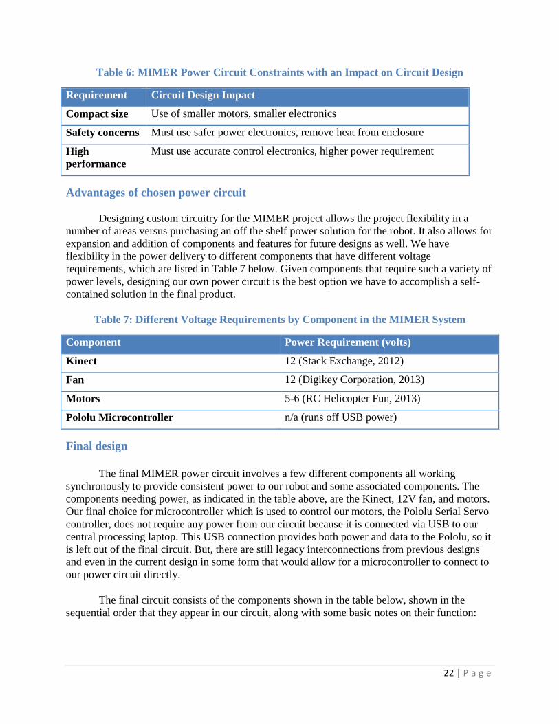
Table 6: MIMER Power Circuit Constraints with an Impact on Circuit Design
Requirement Circuit Design Impact
Compact size Use of smaller motors, smaller electronics
Safety concerns Must use safer power electronics, remove heat from enclosure
High
performance
Must use accurate control electronics, higher power requirement
Advantages of chosen power circuit
Designing custom circuitry for the MIMER project allows the project flexibility in a
number of areas versus purchasing an off the shelf power solution for the robot. It also allows for
expansion and addition of components and features for future designs as well. We have
flexibility in the power delivery to different components that have different voltage
requirements, which are listed in Table 7 below. Given components that require such a variety of
power levels, designing our own power circuit is the best option we have to accomplish a self-
contained solution in the final product.
Table 7: Different Voltage Requirements by Component in the MIMER System
Component Power Requirement (volts)
Kinect 12 (Stack Exchange, 2012)
Fan 12 (Digikey Corporation, 2013)
Motors 5-6 (RC Helicopter Fun, 2013)
Pololu Microcontroller n/a (runs off USB power)
Final design
The final MIMER power circuit involves a few different components all working
synchronously to provide consistent power to our robot and some associated components. The
components needing power, as indicated in the table above, are the Kinect, 12V fan, and motors.
Our final choice for microcontroller which is used to control our motors, the Pololu Serial Servo
controller, does not require any power from our circuit because it is connected via USB to our
central processing laptop. This USB connection provides both power and data to the Pololu, so it
is left out of the final circuit. But, there are still legacy interconnections from previous designs
and even in the current design in some form that would allow for a microcontroller to connect to
our power circuit directly.
The final circuit consists of the components shown in the table below, shown in the
sequential order that they appear in our circuit, along with some basic notes on their function:

23 | P a g e
Table 8: The MIMER Power System Component Overview
Power components Notes
1. 12V, 6A AC to DC wall power converter Plugs into side of MIMER lower case
2. 12V, 14A-h DC battery Sits inside the MIMER lower case. Sits
behind a P-channel MOSFET to switch
3. Switching Printed Circuit Board (PCB) Sits inside the MIMER lower case. Also
distributes power to Kinect
4. Distribution Printed Circuit Board
(PCB)
Sits inside the MIMER torso. Distributes
power to motors, with potential for future
centralization
5. DC-DC converter Sits inside the MIMER torso, as a component
of the Distribution PCB.
The figure below shows the MIMER power flow, including the switching and
distribution circuits:
Figure 14: MIMER Power Flow Chart
First, there is need to switch seamlessly between wall and battery power. When there is
no wall power present, the battery needs to automatically engage to power the whole system. We
integrated this switch on the circuit level. This switch is constructed using a P-channel MOSFET
to toggle back and forth between power sources. During this switch, all of the components in the
MIMER power pipeline will remain active. The figure below shows the switch in a schematic
form. The diode (D) near the 12V input prevents the battery power from flowing back into the
wall source when the battery is engaged.

24 | P a g e
Figure 15: Switch PCB Circuit Schematic
On this circuit, there is also a switch (SW) which turns the entire MIMER system on and
off. A basic toggle switch, shown in the figure below, was integrated into the main 12V line.
This entire switch circuit was placed onto a generic PCB, purchased from Radioshack.
Putting this circuit onto a generic PCB, versus the custom one printed for our power distribution
circuit, made sense because of the simplicity of the switch. The figure below shows a picture of
that PCB, with the different combinations of horizontal and vertical traces clearly visible. This
type of layout was very suitable for our project’s needs.
This PCB, and the distribution PCB, are contained in custom size 3D printed PCB boxes,
to protect the components from the environment, and to protect any users who must perform
maintenance inside the MIMER system. The figure below showcases one of these boxes.
Figure 16: PCB Mounting Box

25 | P a g e
We can also see that the Kinect draws its main power from this switch circuit. The reason
for this was the physical location of the Kinect in the MIMER system – inside of the lower case.
Because of this location, it was deemed simpler to have the Kinect directly plug into the 12V
source before the main 12V output into the torso of the MIMER, where the distribution PCB is
located. The plugs used to interface between the switching and distribution PCB, as well as the
wall power removable plug, is shown below.
The distribution circuit is shown in the figure below.
Figure 17: Distribution Power Circuit
The primary components on this schematic are the fan, DC-DC converter, motors, and
Pololu. The Pololu is shown being power by the computer’s USB connection (CUSB), but is
included in the schematic so its connection with the motors can be seen. It connects directly with
the motors rather than through a control pin plug like the one seen in the schematic, but we will
see that the capability for this expansion is included in the final distribution PCB.
The DC-DC converter takes the 12V input from our switching circuit, and steps it down
to 5V for the motors. This converter has the capability to carry 75W. At peak operation, the
circuit used in MIMER can provide 72W of power (12V * 6A supply current – 72W), but the
additional overhead of this converter is welcome from a safety and reliability standpoint. The
figure below shows this converter, from Car Power Technology (CPT).
From the converter, the rest of the circuit is for powering the motors. The figure below
shows the final distribution PCB that was manufactured for the project, and this PCB will be
discussed in further detail for the rest of this section.

26 | P a g e
Figure 18: Distribution PCB Layout
This design shows a few holdovers from previous power designs, namely the inclusion of
the Arduino power supply and battery/PMOS switching circuit. When the PCB was
manufactured, the requirement of separation between the lower case and torso was unknown. At
that time, the Arduino was the microcontroller being used to control our motors, and it required a
5V power supply. But, the PCB still functions without these components.
The distribution PCB has a 12V input from the switching PCB, which feeds into the fan
power and DC-DC converter. The 5V output from the DC-DC converter then feeds power to all
the motors, with breakaway machine pin headers being put into the PCB where the rows of holes
are connected horizontally. The two rows of vertically connected pins were originally used for
signal input and output, and can still be used for that purpose in future projects. For our final
system, the signal communication with the motors is offloaded from the distribution PCB.
Issues and solutions
The complex requirements of the MIMER robot lead to many potential issues. Because of
the high power requirements of the circuit, mainly owed to the numerous current – drawing servo
motors, battery life was a concern. As a solution, we used a large, 14 amp-hour battery to ensure
our system can run well beyond customer assumptions in ideal conditions.
The heat level of the circuit was also a concern. If the circuit gets too hot, this can cause
safety issues through either physically touching the MIMER case structure or damaging the
components of the robot. The worst case scenario is MIMER catching fire. The solution to avoid
this potential issue is the addition of the fan for heat removal from the internal robot environment
and the selection of heat dissipating components in the circuit design. In our final MIMER
system, the separation of the switch PCB and the distribution PCB between the body and the
torso, respectively, helps with heat management by separating two of the most power consuming,
and potentially hottest, components in the entire system.
Another potential issue is maintaining the integrity of all circuit components when
switching between the battery and wall power supplies. The final circuit has a built-in switch

27 | P a g e
using a P-channel MOSFET that toggles from the wall to the battery supply in the event of
unplugging the DC input, and then back from the battery to DC, given the DC input is connected.
If any components turn off at any point, there will be a severe lapse in MIMER operation,
which would be unacceptable given our design requirements. To work around this issue, we have
integrated capacitors into the circuit design to help maintain the required voltage and current
levels that the motors and Kinect need to have uninterrupted operation during the switching
process.
The final issue that required significant attention in the circuit design process is the
different voltage requirements for different circuit components mentioned above. Stepping
voltages down in a circuit is a relatively straightforward process, but the design of MIMER
brings significant complications. The power requirements of MIMER are low voltage, but high
current given the number of motors. In dropping the voltage in our circuit from 12V for the
Kinect and other miscellaneous components to 5V for the motors required a controlled voltage
drop either through a component or a number of components that could withstand high levels of
power because they will carry large amounts of current to power the motors. To resolve this
issue, we have integrated a 12V to 5V DC-DC converter capable of carrying up to 14A at peak
operation.
Progress through the year
Since the end of the first semester, significant progress was made on the power circuit. At
the end of the 1st semester, there were prototypes and a design methodology selected for the
project. Since then, numerous prototypes have been tested, and the final product integrating two
different Printed Circuit Boards (PCBs) has been integrated into the MIMER system.
In the first semester, we explored a number of different design methodologies for the
MIMER power solution. One design possibility was to “stack” the motors, or put two of the
motors in series with one another, the rest of them laid out in parallel. The logic behind this
architecture was to not have to drop the circuit voltage from 12V that is required for the Kinect,
which would alleviate some of the potential design problems in relying on other components to
carry the voltage drop with such a high current requirement. Such a reliance on, for example, a
+12V/+5V DC-DC regulator, would create a potential single point of failure for the entire robot
architecture. But by choosing a DC-DC regulator with specifications far above the power
capabilities of our power supply and battery, we were able to avoid the possibility of a single
failure point.
In the 1st semester, we validated the switching architecture between the wall and battery,
but not from the battery back to the wall. We validated the need for a parallel layout of the servo
motors for proper power and control. We validated the need for fuse protection for the Kinect
and potential microcontrollers in the circuit. We also spent a great deal of time troubleshooting
different design alternatives in order to select the best possible design to power MIMER.
In the 2nd
semester, we constructed circuits based off our prototypes and carried out
significant tests. We discovered that the power requirements of our circuit were far lower than
28 | P a g e
our initial tests indicated. We tested DC power supplies with varying specifications, and ended
up selected a 12V, 6A capable DC power supply for our primary power. We maintained the
usage of the 12V, 14A-h battery purchased in the 1st semester, even though we could have
integrated a smaller battery into the design. The weight of this battery ended up being a
necessary feature of the robot design, because additional weight was needed to stabilize the torso
and arms during the rapid movements involved in mirroring. We integrated systems of plugs and
switches to make the MIMER system very user friendly overall. We designed and ordered a
custom PCB for power distribution, and integrated a switching circuit onto a generic PCB. We
made the MIMER system run reliably and consistently for long periods of testing, with the final
design operating with minimal power interruptions to the motors.
Ethical considerations
In designing the power circuit for MIMER, there are generally fewer ethical
considerations to be made than in other areas of the project. The most important ethical
consideration is that the power system will meet the customer requirements in all aspects and be
as safe as any commercially available power solution. With the addition of the fan inside the
MIMER torso and the separation of the two critical PCBs, we have taken these safety
considerations into account. Our team feels that the MIMER power system meets all of these
ethical requirements.
Future teams could expand on the compactness of the power system, which would reduce
the overall environmental impact of MIMER if it were to be a commercial product. As we were
producing a prototype, these considerations were less at the forefront of our decision making
process, but could certainly be improved upon.
Conclusions and Future Work
The MIMER team made great progress over the course of the 2013-2014 school year.
The team completed a robot that mimes children in under one second, 60% of the movements are
mirrored well, and MIMER is easily set up and maintained. Although most goals were met, some
tasks can still be upgraded and improved. Features that can be updated are speech recognition
functionality, finger tracking, and battery charging while MIMER is plugged in.
First, speech recognition can be added to MIMER for a more complete experience.
Anschutz Medical Center is not explicitly asking for this feature, but they were not opposed to
the idea. This speech recognition would prompt the user to do a series of movements, and
possibly provide feedback after each individual movement. The system would be beneficial to
the user because this could allow the user to see what sort of progress they are making in the
physical therapy process.
Another feature that can be added to MIMER is finger tracking. The new Xbox Kinect
can track a pinching motion for fingers. This would allow a physical therapy client to work on
finger movements. This would help further with the rehabilitation process.
A functionality that should be added to MIMER is the battery should be charging while
MIMER is plugged into the wall. Currently, the battery needs to be taken out of MIMER before
being charged. This would allow ease of use for the nurse using MIMER.

29 | P a g e
Overall MIMER is complete according to Anschutz Medical Center’s expectations, but
MIMER still can possibly have further functionalities added to him.

30 | P a g e
References
[1] M. Trail, "Learning by Imitation," March 2008. [Online]. Available: http://occupational-
therapy.advanceweb.com/Article/Learning-by-Imitation-1.aspx. [Accessed 15 September 2013].
[2] T. Kim, "The Microsoft Kinect," 27 February 2012. [Online]. Available:
http://tkim2012.blogspot.com/. [Accessed 25 November 2013].
[3] Microsoft Corporation, "Kinect Sensor," Microsoft Corporation, [Online]. Available:
http://msdn.microsoft.com/en-us/library/hh438998.aspx. [Accessed 25 November 2013].
[4] Microsoft, "Introduction to Kinect for Windows Audio," Microsoft, [Online]. Available:
http://www.microsoft.com/en-us/kinectforwindowsdev/Videos.aspx. [Accessed 25 November
2013].
[5] "Getting Started with Microsoft Kinect SDK," I-Programmer.info, 06 February 2012.
[Online]. Available: http://www.i-programmer.info/programming/hardware/2623-getting-started-
with-microsoft-kinect-sdk.html. [Accessed 26 November 2013].
[6] Sparkfun Electronics. Available: https://www.sparkfun.com/products/8897 [Accessed Apr.
26, 2014].

31 | P a g e
Appendix A - Acronyms
AC- Alternating Current
CAD – Computer Aided Design
COM - Communication port
DC – Direct Current
MIMER – Motion Interactive Medical Exercise Robot
MNS – Mirror Neuron System
MOSFET - Metal–Oxide–Semiconductor Field-Effect Transistor
PCB – Printed Circuit Board
PLA - Polylactide
USB - Universal Serial Bus

32 | P a g e
Appendix B – Budget
Table 9: Budget
Component Price Quantity Total Vendor
Robot Components
HS-645MG servo motor $29.29 4 $117.16 RobotShop.com
HS-85BB servo motor $19.95 4 $79.80 RobotShop.com
HS-55 micro servo motor $9.99 6 $59.94 RobotShop.com
Standard servo pan and tilt kit $9.95 2 $19.90 RobotShop.com
Micro servo pan and tilt kit $12.69 2 $25.38 RobotShop.com
2 pack standard servo brackets $11.95 1 $11.95 RobotShop.com
2 pack micro servo brackets $11.95 1 $11.95 RobotShop.com
Mounting hardware (estimated) $5.00 NA $5.00 Home Depot
PLA 3D printing plastic (per
yard) $1.66 100 $166.00 CSU I2P Lab
Total $497.08
Aesthetics
16"x2"x4' wood board $15.00 1 $15.00 Home Depot
3' baseboard trim $5.00 1 $5.00 Home Depot
Black Spray Paint $4.85 1 $4.85 Home Depot
Animal skin $30.00 1 $30.00 Toys R Us
Velcro mounting strips (per yard) $5.00 3 $15.00 Joann's Fabrics
Extra Material (per yard) $4.50 3 $13.50 Joann's Fabrics
Total $83.35
Electronics
DC-DC converter $17.99 1 $17.99 Autek
NMOS $1.06 1 $1.06 Digikey
Diode $1.85 1 $1.85 Digikey
DC power supply $10.00 1 $10.00 Amazon
Plugs and switches $25.00 1 $25.00 Radioshack
Battery $61.00 1 $61.00 BatteriesPlus
PCB $65.70 1 $65.70 ExpressPCB
Pins & jumper wires $38.33 1 $38.33 Sparkfun
Soldering materials $30.45 1 $30.45 Radioshack
Fuses & headers $15.00 1 $15.00 Digikey
Kinect $75.00 1 $75.00 Microsoft
Pololu $39.95 1 $39.95 Pololu
Fan $12.00 1 $12.00 Digikey
Laptop $500.00 1 $500.00 Lenovo
Total $893.33
Grand Total $1,473.76

33 | P a g e
Appendix C – Timelines
For previous timelines see previous report.
Timeline updated 1-8-14
Month
Assignment (Date to be Completed)
Salem
Al-
Aqeel
John
Allison
Trevor
Pier
Jay
Vickers
Lucas
Wadman
Daniel
White
Timeline
Met (Y/N)
Date
Completed
June -
Research
Phase
Research on Body X Y
Microprocessor Selection X X Y
Kinect Data Output Stream X Y
July -
Research
Phase
3-D Movement Decision X X X X Y
Choose Size and Number of Motors X N
Design Hand X X X X N
Aug -
Research
Phase
Prelim Tests X X X X N
How to Interface w/ Motors X X X X Y
Circuit Design X X X X Y
Sept -
Construction
Phase
Timeline 9/11 Email Sudeep TODAY X X X X X X Y
Background Writing Assignment 9/10 X X Y
Project Plan Presentation 9/24 X X Y
Project Website 9/18 Email Dr.
Pasricha 9/11 X X X X X X
Y
Revised Project Plan 9/23 X Y
Notebook Collection 9/23 X X X X X X Y
Update Website 9/15 X Y
Look Into Methods for Hand Tracking X Y
Find Sponsorship 10/1 X N
Materials Selected for Body 9/20 X Y
Overall Size - Sketches Completed
9/20 X
Y
Basic Skeleton Body Constructed 9/20 X Y
Choose Motor Types for Arm And
Order 10/5 X X
N
- Arm Movement Layout with Motors 10/5
X Y
- Circuitry Layout with Motors
Completed 10/5 X
Y
Sensor Reselection (Webcams, Leap, Kinect, Open NI Sensor) 10/1
X
Y
Microcontroller Reselection 9/15 X Y

34 | P a g e
Oct -
Construction
Phase
Testing and Measurement Plan 10/25
Email Sudeep 10/18 X
Y-N
Notebook Collection 10/14 Mech 10/3 X X X X X X Y
First Round of Concepts Complete Mech 10/10
X X Y
Design Your Future Day 10/16 X X X X X X Y
Update Website 10/15 X Y
Project Presentation 10/25 X Y
Order Circuit Parts 11/3 X Y
Motors and Controller Interfacing
10/30 Completed Nov 2nd
X
N
Choose Motor Types for Arm and
Order 10/13 X
Y
Funding Letter Sent to Companies
10/11 finished 10/16
X
N
Preliminary Design Base for Robot
10/30 X
Y
Stuffing and shell for bear ideas 11/3 X Y
Sensor and Computer Testing 10/30 X Y
Start to Implement on Body 10/30 X Y
Nov - Debug
Phase
Oral Presentation 12/11 X X X X X X Y 12-11
First Round of Feasibility analysis started 11/14
X X Y 11-14
Notebook Check 11/14 Mech E 11/5 X X X X X X Y 11-14
Written Report 12/3 X N 12-6
Elevator Speech 12/3 X Y 12-3
Plans for next Semester 12/3 X Y 11-25
Peer and Self Evaluation 12/3 X X X X X X N 12-13
Update Website 11/15 X Y 11-15
Research Batteries for Battery
Powered 11/23 X
Y 11-10
Find another power supply to test
circuit 12/22 X
Order Circuit Parts 11/3 X Y 11-3
Stuffing and shell for bear ideas 11/3 X Y 11-3
Testing from Sensor to
Microcontroller 11/10 X
N 11-15
Code for Base 11/30 X Y 11-10
Dec -
Administration
Phase
Oral Presentation 12/11 X Y 12-11
Critical Design Review Mech E 12/10
- presentation X X
NA
Elevator Speech 12/3 X Y 12-3
Written Report 12/3 Mech 12/5 X Y 12-6
Design Notebooks 12/10 X X X X X X
Plans for next Semester 12/13 X Y 11-25
Peer and Self Evaluation 12/13 X X X X X X Y 12-13

35 | P a g e
Special Cases Coding 12/21 X N
Rules for Use 12/21 X
Update Website 12/15 X Y 12-15
Set Up Time with Anschutz to Test
12/21 X
N
Circuit Testing - 2 solutions for
Voltage Regulation on Pis 12/22
X
Y 12-8
Circuit Testing - Fusing 12/31 X Y 12-20
Circuit Testing - Wall Switching to
Battery and Vice Versa 12/22
X
Y 11-13
Circuit Testing - Testing solutions for
voltage regulation 12/31
X
N
Coding - No Crashing Code 12/7 X Y 12-7
Coding - Bouncing motors is not
noticeable on arms 12/7
X
Y 12-7
Coding - Debug of code for Pipeline 12/31
X X N 1-11
Mechanical - Concept for Gearing of
DC Motor 12/31
X
Mechanical - Concept Design of
Hands Complete 12/31
X
Y 12-7
Mechanical - Testing Torque of new
750mA motors 12/31 X
Y 12-20
Mechanical - CAD final concept
drawing 12/11 X
N
Mechanical - Skin for testing 12/31 X
First Semester
Deliverables
Robot with moving arms taking input
from sensor and outputs to motors X
Y 1-11
- Prototypical Skeleton Design with Motors
X Y
- Microcontroller Selection X Y 10-8
- Sensor Selection X Y 6-15
- 70% Code Completed - Arm
Mimicry, Speech Recognition, User Selection
X
Y 11-23
- Meeting Clinical Criteria - Arm
Mirroring - no DC motors - no hands
X
Y 1-11
- Slow Mimicry of Children (1 sec Delay)
X Y 1-11
- Power Circuit for Arms Completely
Built X
N
- Speech Recognition Functionality (moved to second semester)
X
N
Jan -
Construction
Phase
Update Website 1/15 X
Test with Child Week of Jan 15th X
N End of
Jan
Revise Timeline 1/20 X

36 | P a g e
Circuit Testing - Solution for
discharging one end of the circuit and
keeping a constant voltage wall and battery 1/10
X
Y 1-10
Circuit Testing - Testing solution for discharging one end of the circuit and
keeping a constant voltage - wall and
battery 1/15
X
N
Circuit Testing - Power Circuit
Completely Constructed 1/31
X
Coding - Code takes in input for arms and outputs to motors 1/15
X
Y 1-11
Coding - Getting code to work over
network at school 1/19
X
N
Coding - Speed up Coding to sub 1
sec delay from Kinect to motors 1/31
X
Y 1-11
Coding - Look into solutions for
bouncing motors and have a solution 1/19
X
Coding - 1st Write-up of hand
tracking algorithm 1/31 * X
Mechanical - Specific Idea for Stand
Solution 1/15 X
Mechanical - Have in hand solution for stand 1/31
X
Mechanical - Construct Gearing for
DC Motors 1/31
X
Build 2nd prototype of arms 1/15 -
new motors X
Y 1-15
Mechanical Debug Mechanical Issues
with Arm 1/31 X
Feb - Debug
Phase
Mechanical - Construct Hands with
Motors 1/31* X
Set Up Another Testing Time 1/31 X
Update Website 2/15 X
Design Notebooks X X X X X X
Circuit Testing - Debug Small Issues
2/7 X
Complete Test of MIMER without
hands 2/15 X
Test with Child/Anschutz week of Feb 24
X
Coding - Move Executable to Pi's 2/28 X
Coding - Write Speech Recognition Code 2/15
X
Coding - Debug Hand Tracking
Algorithm 2/28 X
Mechanical - Debug Issues with
Hands 2/28 X
Mechanical - Final Ideas for Skin 2/15 X
Mechanical - Add DC motors to cart
2/15 X
Mechanical - Add hands to MIMER 2/28
X

37 | P a g e
Mar - Small
Construction
Phase
Mechanical - Dress MIMER 2/28 X
PCB layout 2/28 X
Update Website 3/15 X
Design Notebooks 3/
Coding - All Coding Running on Pis
3/31 X X
Coding - Speech Recognition
Complete 3/15
X
Coding - Complete Hand Tracking
3/15 X
Mechanical - Debug and Issues with Mechanical System
X X
Circuit - Debug Any Issues with
Electrical System X X
Apr - Last
Debug Phase
Meet All Final Deliverables 3/31 X
Written Report X
Recommendation for Project
Continuation X X
Edays X
Peer and Self Evaluation X X X X X X
Oral Presentation X
Second
Semester
Deliverables
Any Last Debug X X X X X X
Final Complete Project X X X X X X
Arms Mirroring Child X X X X X X
Hands Mirroring Child X X X X X X
Aesthetically Pleasing X X X X X X
Exceeds all of Anschutz's
Expectations X X X X X X
Timeline updated 1-23-14
Month
Assignment (Date to be Completed)
Salem Al-
Aqeel
John Alliso
n
Trevo
r Pier
Jay Vicker
s
Lucas Wadma
n
Daniel
White
Timeline
Met (Y/N) Date
Complete
d
June - Research
Phase
Research on Body X Y
Microprocessor Selection X X Y
Kinect Data Output Stream X Y
July - Research
Phase
3-D Movement Decision X X X X Y
Choose Size and Number of Motors X N
Design Hand X X X X N
Aug -
Research Phase
Prelim Tests X X X X N
How to Interface w/ Motors X X X X Y
Circuit Design X X X X Y
Sept - Timeline 9/11 Email Sudeep TODAY X X X X X X Y

38 | P a g e
Construction
Phase Background Writing Assignment 9/10 X X Y
Project Plan Presentation 9/24 X X Y
Project Website 9/18 Email Dr. Pasricha 9/11 X X X X X X Y
Revised Project Plan 9/23 X Y
Notebook Collection 9/23 X X X X X X Y
Update Website 9/15 X Y
Look Into Methods for Hand Tracking X Y
Find Sponsorship 10/1 X N
Materials Selected for Body 9/20 X Y
Overall Size - Sketches Completed 9/20 X Y
Basic Skeleton Body Constructed 9/20 X Y
Choose Motor Types for Arm And Order 10/5 X X N
- Arm Movement Layout with Motors 10/5 X Y
- Circuitry Layout with Motors Completed 10/5 X Y
Sensor Reselection (Webcams, Leap, Kinect,
Open NI Sensor) 10/1
X
Y
Microcontroller Reselection 9/15 X Y
Oct -
Construction Phase
Testing and Measurement Plan 10/25 Email
Sudeep 10/18 X
Y-N
Notebook Collection 10/14 Mech 10/3 X X X X X X Y
First Round of Concepts Complete Mech 10/10 X X Y
Design Your Future Day 10/16 X X X X X X Y
Update Website 10/15 X Y
Project Presentation 10/25 X Y
Order Circuit Parts 11/3 X Y
Motors and Controller Interfacing 10/30 Completed Nov 2nd
X
N
Choose Motor Types for Arm and Order 10/13 X Y
Funding Letter Sent to Companies 10/11 finished
10/16 X
N
Preliminary Design Base for Robot 10/30 X Y
Stuffing and shell for bear ideas 11/3 X Y
Sensor and Computer Testing 10/30 X Y
Start to Implement on Body 10/30 X Y
Nov - Debug Phase
Oral Presentation 12/11 X X X X X X Y 12-11
First Round of Feasibility analysis started 11/14 X X Y 11-14
Notebook Check 11/14 Mech E 11/5 X X X X X X Y 11-14
Written Report 12/3 X N 12-6
Elevator Speech 12/3 X Y 12-3
Plans for next Semester 12/3 X Y 11-25
Peer and Self Evaluation 12/3 X X X X X X N 12-13
Update Website 11/15 X Y 11-15

39 | P a g e
Research Batteries for Battery Powered 11/23 X Y 11-10
Find another power supply to test circuit 12/22 X
Order Circuit Parts 11/3 X Y 11-3
Stuffing and shell for bear ideas 11/3 X Y 11-3
Testing from Sensor to Microcontroller 11/10 X N 11-15
Code for Base 11/30 X Y 11-10
Dec -
Administration Phase
Oral Presentation 12/11 X Y 12-11
Critical Design Review Mech E 12/10 - presentation
X X NA
Elevator Speech 12/3 X Y 12-3
Written Report 12/3 Mech 12/5 X Y 12-6
Design Notebooks 12/10 X X X X X X
Plans for next Semester 12/13 X Y 11-25
Peer and Self Evaluation 12/13 X X X X X X Y 12-13
Special Cases Coding 12/21 X N
Rules for Use 12/21 X
Update Website 12/15 X Y 12-15
Set Up Time with Anschutz to Test 12/21 X N
Circuit Testing - 2 solutions for Voltage
Regulation on Pis 12/22
X
Y 12-8
Circuit Testing - Fusing 12/31 X Y 12-20
Circuit Testing - Wall Switching to Battery and
Vice Versa 12/22
X
Y 11-13
Circuit Testing - Testing solutions for voltage regulation 12/31
X
N
Coding - No Crashing Code 12/7 X Y 12-7
Coding - Bouncing motors is not noticeable on
arms 12/7 X
Y 12-7
Coding - Debug of code for Pipeline 12/31 X X N 1-11
Mechanical - Concept for Gearing of DC Motor 12/31
X
Mechanical - Concept Design of Hands
Complete 12/31 X
Y 12-7
Mechanical - Testing Torque of new 750mA
motors 12/31 X
Y 12-20
Mechanical - CAD final concept drawing 12/11 X N
Mechanical - Skin for testing 12/31 X
First Semester
Deliverables
Robot with moving arms taking input from
sensor and outputs to motors
X
Y 1-11
- Prototypical Skeleton Design with Motors X Y
- Microcontroller Selection X Y 10-8
- Sensor Selection X Y 6-15
- 70% Code Completed - Arm Mimicry, Speech
Recognition, User Selection
X
Y 11-23

40 | P a g e
- Meeting Clinical Criteria - Arm Mirroring - no DC motors - no hands
X
Y 1-11
- Slow Mimicry of Children (1 sec Delay) X Y 1-11
- Power Circuit for Arms Completely Built X N
- Speech Recognition Functionality (moved to
second semester)
X
N
Jan -
Construction Phase
Update Website 1/15 X
Test with Child Week of Jan 15th X
N End of Jan
Revise Timeline 1/20 X
Circuit Testing - Solution for discharging one end of the circuit and keeping a constant voltage
wall and battery 1/10
X
Y 1-10
Circuit Testing - Testing solution for discharging
one end of the circuit and keeping a constant voltage - wall and battery 1/15
X
N
Circuit Testing - Power Circuit Completely
Constructed 1/31 X
Coding - Code takes in input for arms and outputs to motors 1/15
X
Y 1-11
Coding - Getting code to work over network at
school 1/19 X
N
Coding - Speed up Coding to sub 1 sec delay
from Kinect to motors 1/31
X
Y 1-11
Coding - Look into solutions for bouncing motors and have a solution 1/19
X
Coding - 1st Write-up of hand tracking algorithm
1/31 * X
Mechanical - Specific Idea for Stand Solution
1/15 X
Mechanical - Have in hand solution for stand 1/31
X
Mechanical - Construct Gearing for DC Motors
1/31 X
Build 2nd prototype of arms 1/15 - new motors X Y 1-15
Mechanical Debug Mechanical Issues with Arm 1/31
X
Mechanical - Construct Hands with Motors
1/31* X
Set Up Another Testing Time 1/31 X
Feb - Debug
Phase
Update Website 2/15 X
Design Notebooks X X X X X X
Circuit Testing - Debug Small Issues 2/7 X
Complete Test of MIMER without hands 2/15 X
Test with Child/Anschutz week of Feb 24 X
Coding - Move Executable to Pi's 2/28 X
Coding - Write Speech Recognition Code 2/15 X
Coding - Debug Hand Tracking Algorithm 2/28 X

41 | P a g e
Mechanical - Debug Issues with Hands 2/28 X
Mechanical - Final Ideas for Skin 2/15 X
Mechanical - Add DC motors to cart 2/15 X
Mechanical - Add hands to MIMER 2/28 X
Mechanical - Dress MIMER 2/28 X
PCB layout 2/28 X
Mar - Small
Construction Phase
Update Website 3/15 X
Design Notebooks 3/
Coding - All Coding Running on Pis 3/31 X X
Coding - Speech Recognition Complete 3/15 X
Coding - Complete Hand Tracking 3/15 X
Mechanical - Debug and Issues with Mechanical
System X X
Circuit - Debug Any Issues with Electrical
System X X
Meet All Final Deliverables 3/31 X
Apr - Last
Debug Phase
Written Report X
Recommendation for Project Continuation X X
Edays X
Peer and Self Evaluation X X X X X X
Oral Presentation X
Any Last Debug X X X X X X
Second Semester
Deliverables
Final Complete Project X X X X X X
Arms Mirroring Child X X X X X X
Hands Mirroring Child X X X X X X
Aesthetically Pleasing X X X X X X
Exceeds all of Anschutz's Expectations X X X X X X
Timeline updated 2-9-14
Month
Assignment (Date to be Completed)
Salem
Al-Aqeel
John
Allison
Trevor
Pier
Jay
Vickers
Lucas
Wadman
Daniel
White
Timeline
Met (Y/N)
Date Completed
June - Research
Phase
Research on Body X Y
Microprocessor Selection X X Y
Kinect Data Output Stream X Y
July -
Research Phase
3-D Movement Decision X X X X Y
Choose Size and Number of Motors X N
Design Hand X X X X N
Aug -
Research Phase
Prelim Tests X X X X N
How to Interface w/ Motors X X X X Y
Circuit Design X X X X Y
Sept - Timeline 9/11 Email Sudeep TODAY X X X X X X Y

42 | P a g e
Construction
Phase Background Writing Assignment 9/10 X X Y
Project Plan Presentation 9/24 X X Y
Project Website 9/18 Email Dr. Pasricha 9/11 X X X X X X Y
Revised Project Plan 9/23 X Y
Notebook Collection 9/23 X X X X X X Y
Update Website 9/15 X Y
Look Into Methods for Hand Tracking X Y
Find Sponsorship 10/1 X N
Materials Selected for Body 9/20 X Y
Overall Size - Sketches Completed 9/20 X Y
Basic Skeleton Body Constructed 9/20 X Y
Choose Motor Types for Arm And Order 10/5 X X N
- Arm Movement Layout with Motors 10/5 X Y
- Circuitry Layout with Motors Completed 10/5 X Y
Sensor Reselection (Webcams, Leap, Kinect, Open NI Sensor) 10/1
X
Y
Microcontroller Reselection 9/15 X Y
Oct -
Construction Phase
Testing and Measurement Plan 10/25 Email
Sudeep 10/18 X
Y-N
Notebook Collection 10/14 Mech 10/3 X X X X X X Y
First Round of Concepts Complete Mech 10/10 X X Y
Design Your Future Day 10/16 X X X X X X Y
Update Website 10/15 X Y
Project Presentation 10/25 X Y
Order Circuit Parts 11/3 X Y
Motors and Controller Interfacing 10/30
Completed Nov 2nd
X
N
Choose Motor Types for Arm and Order 10/13 X Y
Funding Letter Sent to Companies 10/11 finished 10/16
X N
Preliminary Design Base for Robot 10/30 X Y
Stuffing and shell for bear ideas 11/3 X Y
Sensor and Computer Testing 10/30 X Y
Start to Implement on Body 10/30 X Y
Nov - Debug
Phase
Oral Presentation 12/11 X X X X X X Y 12-11
First Round of Feasibility analysis started 11/14 X X Y 11-14
Notebook Check 11/14 Mech E 11/5 X X X X X X Y 11-14
Written Report 12/3 X N 12-6
Elevator Speech 12/3 X Y 12-3
Plans for next Semester 12/3 X Y 11-25
Peer and Self Evaluation 12/3 X X X X X X N 12-13
Update Website 11/15 X Y 11-15

43 | P a g e
Research Batteries for Battery Powered 11/23 X Y 11-10
Find another power supply to test circuit 12/22 X
Order Circuit Parts 11/3 X Y 11-3
Stuffing and shell for bear ideas 11/3 X Y 11-3
Testing from Sensor to Microcontroller 11/10 X N 11-15
Code for Base 11/30 X Y 11-10
Dec -
Administration
Phase
Oral Presentation 12/11 X Y 12-11
Critical Design Review Mech E 12/10 - presentation
X X NA
Elevator Speech 12/3 X Y 12-3
Written Report 12/3 Mech 12/5 X Y 12-6
Design Notebooks 12/10 X X X X X X
Plans for next Semester 12/13 X Y 11-25
Peer and Self Evaluation 12/13 X X X X X X Y 12-13
Special Cases Coding 12/21 X N
Rules for Use 12/21 X
Update Website 12/15 X Y 12-15
Set Up Time with Anschutz to Test 12/21 X N
Circuit Testing - 2 solutions for Voltage
Regulation on Pis 12/22
X
Y 12-8
Circuit Testing - Fusing 12/31 X Y 12-20
Circuit Testing - Wall Switching to Battery and Vice Versa 12/22
X
Y 11-13
Circuit Testing - Testing solutions for voltage
regulation 12/31
X
N
Coding - No Crashing Code 12/7 X Y 12-7
Coding - Bouncing motors is not noticeable on
arms 12/7 X
Y 12-7
Coding - Debug of code for Pipeline 12/31 X X N 1-11
Mechanical - Concept for Gearing of DC Motor
12/31 X
Mechanical - Concept Design of Hands Complete 12/31
X Y 12-7
Mechanical - Testing Torque of new 750mA
motors 12/31 X
Y 12-20
Mechanical - CAD final concept drawing 12/11 X N
Mechanical - Skin for testing 12/31 X
First Semester
Deliverables
Robot with moving arms taking input from sensor
and outputs to motors
X
Y 1-11
- Prototypical Skeleton Design with Motors X Y
- Microcontroller Selection X Y 10-8
- Sensor Selection X Y 6-15
- 70% Code Completed - Arm Mimicry, Speech Recognition, User Selection
X
Y 11-23

44 | P a g e
- Meeting Clinical Criteria - Arm Mirroring - no DC motors - no hands
X
Y 1-11
- Slow Mimicry of Children (1 sec Delay) X Y 1-11
- Power Circuit for Arms Completely Built X N
- Speech Recognition Functionality (moved to
second semester)
X
N
Jan -
Construction Phase
Update Website 1/15 X
Test with Child Week of Jan 15th X
N End of
Jan
Revise Timeline 1/20 X
Circuit Testing - Solution for discharging one end of the circuit and keeping a constant voltage wall
and battery 1/10
X
Y 1-10
Circuit Testing - Testing solution for discharging
one end of the circuit and keeping a constant
voltage - wall and battery 1/15
X
N
Circuit Testing - Power Circuit Completely Constructed 1/31
X
Coding - Code takes in input for arms and outputs
to motors 1/15
X
Y 1-11
Coding - Getting code to work over network at school 1/19
X N
Coding - Speed up Coding to sub 1 sec delay from
Kinect to motors 1/31
X
Y 1-11
Coding - Look into solutions for bouncing motors
and have a solution 1/19
X
Coding - 1st Write-up of hand tracking algorithm
1/31 * X
Mechanical - Specific Idea for Stand Solution 1/15 X
Mechanical - Have in hand solution for stand 1/31 X
Mechanical - Construct Gearing for DC Motors
1/31 X
Build 2nd prototype of arms 1/15 - new motors X Y 1-15
Mechanical Debug Mechanical Issues with Arm 1/31
X
Mechanical - Construct Hands with Motors 1/31* X
Set Up Another Testing Time 1/31 X
Feb - Debug Phase
Update Website 2/15 X
Design Notebooks X X X X X X
Circuit Testing - Debug Small Issues 2/7 X
Complete Test of MIMER without hands 2/15 X
Test with Child/Anschutz week of Feb 24 X
Coding - Move Executable to Pi's 2/28 X
Coding - Write Speech Recognition Code 2/15 X
Coding - Debug Hand Tracking Algorithm 2/28 X
Mechanical - Debug Issues with Hands 2/28 X

45 | P a g e
Mechanical - Final Ideas for Skin 2/15 X
Mechanical - Add DC motors to cart 2/15 X
Mechanical - Add hands to MIMER 2/28 X
Mechanical - Dress MIMER 2/28 X
PCB layout 2/28 X
Mar - Small
Construction
Phase
Update Website 3/15 X
Design Notebooks 3/
Coding - All Coding Running on Pis 3/31 X X
Coding - Speech Recognition Complete 3/15 X
Coding - Complete Hand Tracking 3/15 X
Mechanical - Debug and Issues with Mechanical
System X X
Circuit - Debug Any Issues with Electrical System X X
Meet All Final Deliverables 3/31 X
Apr - Last
Debug Phase
Written Report X
Recommendation for Project Continuation X X
Edays X
Peer and Self Evaluation X X X X X X
Oral Presentation X
Any Last Debug X X X X X X
Second
Semester
Deliverables
Final Complete Project X X X X X X
Arms Mirroring Child X X X X X X
Hands Mirroring Child X X X X X X
Aesthetically Pleasing X X X X X X
Exceeds all of Anschutz's Expectations X X X X X X
Timeline updated 4-24-14
Month
Assignment (Date to be Completed)
Salem Al-
Aqeel
John
Allison
Trevor
Pier
Jay
Vickers
Lucas
Wadman
Daniel
White
Timeline
Met (Y/N)
Date Completed
June -
Research Phase
Research on Body X Y
Microprocessor Selection X X Y
Kinect Data Output Stream X Y
July -
Research
Phase
3-D Movement Decision X X X X Y
Choose Size and Number of Motors X N
Design Hand X X X X N
Aug -
Research
Phase
Prelim Tests X X X X N
How to Interface w/ Motors X X X X Y
Circuit Design X X X X Y
Sept -
Construction
Phase
Timeline 9/11 Email Sudeep TODAY X X X X X X Y
Background Writing Assignment 9/10 X X Y
Project Plan Presentation 9/24 X X Y

46 | P a g e
Project Website 9/18 Email Dr. Pasricha 9/11 X X X X X X Y
Revised Project Plan 9/23 X Y
Notebook Collection 9/23 X X X X X X Y
Update Website 9/15 X Y
Look Into Methods for Hand Tracking X Y
Find Sponsorship 10/1 X N
Materials Selected for Body 9/20 X Y
Overall Size - Sketches Completed 9/20 X Y
Basic Skeleton Body Constructed 9/20 X Y
Choose Motor Types for Arm And Order 10/5 X X N
- Arm Movement Layout with Motors 10/5 X Y
- Circuitry Layout with Motors Completed 10/5 X Y
Sensor Reselection (Webcams, Leap, Kinect,
Open NI Sensor) 10/1 X
Y
Microcontroller Reselection 9/15 X Y
Oct - Construction
Phase
Testing and Measurement Plan 10/25 Email Sudeep 10/18
X Y-N
Notebook Collection 10/14 Mech 10/3 X X X X X X Y
First Round of Concepts Complete Mech 10/10 X X Y
Design Your Future Day 10/16 X X X X X X Y
Update Website 10/15 X Y
Project Presentation 10/25 X Y
Order Circuit Parts 11/3 X Y
Motors and Controller Interfacing 10/30
Completed Nov 2nd X
N
Choose Motor Types for Arm and Order 10/13 X Y
Funding Letter Sent to Companies 10/11 finished
10/16 X
N
Preliminary Design Base for Robot 10/30 X Y
Stuffing and shell for bear ideas 11/3 X Y
Sensor and Computer Testing 10/30 X Y
Start to Implement on Body 10/30 X Y
Nov - Debug
Phase
Oral Presentation 12/11 X X X X X X Y 12-11
First Round of Feasibility analysis started 11/14 X X Y 11-14
Notebook Check 11/14 Mech E 11/5 X X X X X X Y 11-14
Written Report 12/3 X N 12-6
Elevator Speech 12/3 X Y 12-3
Plans for next Semester 12/3 X Y 11-25
Peer and Self Evaluation 12/3 X X X X X X N 12-13
Update Website 11/15 X Y 11-15
Research Batteries for Battery Powered 11/23 X Y 11-10
Find another power supply to test circuit 12/22 X N 2/5
Order Circuit Parts 11/3 X Y 11-3
Stuffing and shell for bear ideas 11/3 X Y 11-3
Testing from Sensor to Microcontroller 11/10 X N 11-15
Code for Base 11/30 X Y 11-10

47 | P a g e
Dec -
Administration
Phase
Oral Presentation 12/11 X Y 12-11
Critical Design Review Mech E 12/10 -
presentation X X
NA
Elevator Speech 12/3 X Y 12-3
Written Report 12/3 Mech 12/5 X Y 12-6
Design Notebooks 12/10 X X X X X X Y 12/10
Plans for next Semester 12/13 X Y 11-25
Peer and Self Evaluation 12/13 X X X X X X Y 12-13
Special Cases Coding 12/21 X N 4/11
Rules for Use 12/21 X Y 12/21
Update Website 12/15 X Y 12-15
Circuit Testing - 2 solutions for Voltage Regulation on Pis 12/22
X Y 12-8
Circuit Testing - Fusing 12/31 X Y 12-20
Circuit Testing - Wall Switching to Battery and
Vice Versa 12/22 X
Y 11-13
Circuit Testing - Testing solutions for voltage
regulation 12/31 X
N 2/28
Coding - No Crashing Code 12/7 X Y 12-7
Coding - Bouncing motors is not noticeable on
arms 12/7 X
Y 12-7
Coding - Debug of code for Pipeline 12/31 X X N 1-11
Mechanical - Concept Design of Hands Complete
12/31 X
Y 12-7
Mechanical - Testing Torque of new 750mA motors 12/31
X Y 12-20
Mechanical - CAD final concept drawing 12/11 X N 3/1
Mechanical - Skin for testing 12/31 X N 3/7
First Semester
Deliverables
Robot with moving arms taking input from sensor and outputs to motors
X Y 1-11
- Prototypical Skeleton Design with Motors X Y
- Microcontroller Selection X Y 10-8
- Sensor Selection X Y 6-15
- 70% Code Completed - Arm Mimicry, Speech
Recognition, User Selection X
Y 11-23
- Meeting Clinical Criteria - Arm Mirroring - no DC motors - no hands
X Y 1-11
- Slow Mimicry of Children (1 sec Delay) X Y 1-11
- Power Circuit for Arms Completely Built X N 3/31
Jan - Construction
Phase
Update Website 1/15 X N 1/25
Revise Timeline 1/20 X N 1-28
Circuit Testing - Solution for discharging one end
of the circuit and keeping a constant voltage wall
and battery 1/10
X
Y 1-10
Circuit Testing - Testing solution for discharging
one end of the circuit and keeping a constant voltage - wall and battery 1/15
X
N 3/31
Circuit Testing - Power Circuit Completely
Constructed 1/31 X
Y 1/31

48 | P a g e
Coding - Code takes in input for arms and outputs
to motors 1/15 X
Y 1-11
Coding - Getting code to work over network at
school 1/19 X
N 2/1
Coding - Speed up Coding to sub 1 sec delay from Kinect to motors 1/31
X Y 1-11
Coding - Look into solutions for bouncing motors and have a solution 1/19
X N 2/14
Mechanical - Specific Idea for Stand Solution 1/15 X N 2/5
Build 2nd prototype of arms 1/15 - new motors X Y 1-15
Mechanical Debug Mechanical Issues with Arm 1/31
X Y 1/31
Set Up Another Testing Time 1/31 X N 2/5
Feb - Debug
Phase
Update Website 2/15 X Y 2/15
Design Notebooks 2/24 X X X X X X Y 2/24
Circuit Testing - Debug Small Issues 2/7 X Y 2/7
Circuit Testing - Testing solution for discharging one end of the circuit and keeping a constant
voltage - wall and battery 1/15
X
N 2/28
Complete Test of MIMER without hands 2/15 X Y 2/2
Coding - Fixing Speed of Sending Information 2/23
X N 4/11
Coding - Motors Not Bouncing 2/28 X Y 2/23
Mechanical - Debug Issues with Hands 2/28 X Y 2/28
Mechanical - Construct Hands with Motors 2/28* X Y 2/28
Mechanical - Body Constructed and Complete 2/28
X Y 2/16
Mechanical - Final Ideas for Skin 2/28 X Y 2/28
Mechanical - Final Box 2/28 X N 3/23
Mechanical - Add hands to MIMER 2/28 X N 3/7
Mechanical - Dress MIMER 3/5 X N 3/23
PCB layout 2/28 X N 3/31
Mar - Small
Construction Phase
Update Website 3/15 X Y 3/15
Design Notebooks 3/31 Y 3/31
Meet with Dan Ferguson End of March X N 4/18
Mechanical - Debug Issues with Mechanical System
X X Y 3/29
Circuit - Debug Any Issues with Electrical System X X Y 3/29
Meet All Final Deliverables 3/31 X N 4/11
Apr - Last Debug Phase
Written Report X
Recommendation for Project Continuation X X
Edays X Y 4/25
Peer and Self Evaluation X X X X X X
Oral Presentation X
Any Last Debug X X X X X X Y 4/24
Second Semester
Deliverables
Final Complete Project X X X X X X Y 4/24
Arms Mirroring Child Sub 1 second X X X X X X Y 4/12
Aesthetically Pleasing X X X X X X Y 3/31

49 | P a g e
Exceeds all of Anschutz's Expectations X X X X X X Awaiting
Critique

50 | P a g e
Appendix D – Funding Documents
The MIMER project has had a significant self-funding component because of its large scale
and associated costs. We have pursued sponsorship from a number of different organizations,
and in November 2013 we successfully received sponsorship from Agilent Technologies after a
competitive sponsorship process. Attached in this Appendix are the funding request letters used
to solicit sponsorship for the project, and the message of thanks extended to Agilent after we
were selected for their sponsorship.
«Company_Name»
«Local_Address»
To Whom It May Concern,
Motion Interactive Medical Exercise Robot (MIMER) is an electrical engineering senior
design project at Colorado State University. The project is being performed in conjunction with
Anschutz Medical Center in Denver, CO.
What is this project?
The goal of the project is to design and build a robot to interact with developmentally
disabled children who receive treatment at Anschutz and help them achieve developmental
milestones, such as reaching for a ball or singing the itsy bitsy spider song. These milestones can
be more difficult to achieve for children with developmental disabilities, and the key for reaching
the milestones is repetition. Robots are great at many things, including repetition! MIMER will
integrate motion-sensing technologies with our team’s custom software algorithms to interact
with children, mirror their motions, and give motion prompts! And last but not least, MIMER
will have a friendly exterior like a Teddy Bear or other cuddly creature to encourage children to
interact with it. We are asking if «Company_Name» would be willing to help us make MIMER a
reality through financial sponsorship.
Our project is ambitious, but our multidisciplinary team of electrical, computer, and
mechanical engineering students is fully capable of accomplishing the goals. We are designing a
robot that will sense motion and be friendly and inviting to developmentally disabled children
from the ground up. We have plans to deliver a fully functional robot to Anschutz for testing
with their clients by the end of January. We have already invested significant amounts of time
and energy, and the last component we need to see MIMER through to its full potential is
funding.
So…what do you need?
At this point, our project is in need of funding resources so we can purchase the advanced
sensor technologies, robot components, and other components as we encounter project bumps.
We currently anticipate needing a total sponsorship of $2000 for our project, so any funding your
organization could provide would be appreciated greatly. A detailed budget breakdown is
available by request. Donations will be made through a secure web portal on the Electrical and
Computer Engineering web page.

51 | P a g e
How will this benefit «Company_Name»?
There are a number of ways in which sponsorship would benefit «Company_Name». This
project will have exposure not just throughout Colorado State University through our coursework
but also within the Fort Collins and Anschutz communities when we are eventually running trial
tests with the robot.
If «Company_Name» were to offer assistance for our project, we would be sure to
prominently include your branding on our team shirts, deliverables like our paper and
presentation, or even on the MIMER robot itself.
We from the MIMER team thank you at «Company_Name» for your time and consideration
of this funding request. If you have any questions, please contact our fundraising lead, Luke
Wadman ([email protected]), our faculty advisor, Dr. Sudeep Pasricha
([email protected]), or the head of ECE senior design, Olivera Notaros
([email protected]). You can find more information at our project web page
(http://www.engr.colostate.edu/ece-sr-design/AY13/MIMER/index.html).
Sincerely,
Electrical and Computer Engineering
MIMERS
Mechanical Engineering MIMERS
Salem Al-Aqeel, Daniel White, Jay Vickers,
Luke Wadman
John Allison, Trevor Pier

52 | P a g e
Appendix E – Thank You Letter – Agilent
To Whom It May Concern,
We would like to extend our thanks to your team of Dan Ferguson, Mike Craig, and Mike
Hawes, and the rest of the Agilent organization for selecting our Motion Interactive Medical
Exercise Robot (MIMER) senior design project as 1st place in the 2013 Agilent Senior Design
sponsorship competition!
This sponsorship allows us the opportunity to see our project through to completion, without
unnecessary hiccups or financial obligations to our individual team members. This is the kind of
flexibility our small team needs, and it will allow us to fully realize the potential of our project
by the end of next April.
With this generous sponsorship from Agilent, we are committed to including Agilent logos
and thanks on all our project materials, including reports, presentations, and our website. In
addition, we will be working with a member of the sponsorship committee to organize a site visit
to Agilent in the spring time frame, when MIMER will be demonstration-ready. We will also be
relaying Agilent’s generous status to our collaborators at Anschutz Medical Center.
We are enormously excited that Agilent is committed to MIMER, the next generation
apparatus for measuring effective treatment of developmental disabilities in a clinical
environment. With Agilent’s sponsorship, we are that much closer to helping Anschutz’s team of
expert clinicians usher in a new era of diagnosing, treating, and rehabilitating children with
developmental disabilities.
We again extend our humble thanks, and look forward to working with you in the future as
MIMER comes closer to a reality.
Sincerely,
Electrical and Computer Engineering MIMERS
Mechanical Engineering MIMERS
Salem Al-Aqeel, Daniel White, Jay Vickers, Luke
Wadman
John Allison, Trevor Pier

53 | P a g e
Appendix F – Previous Circuit Layouts
This appendix includes the initial circuit diagrams from the project, where different
alternatives were being tested.
The diagram below is a completed circuit that includes the switching and power
distribution circuits all on one schematic. This was a design we did not end up using, but could
be used as a design option for future projects.
Figure 19: Previous Circuit Layout
The below layout diagram is an example of the “stacked” circuit layout approach that
proved to be invalid for our purposes given the need for the signal-line inputs of the motors to
operate at a common ground. With this design, the ground for the top motor would “float” at the
input for the bottom motor, allowing for correct voltages across the motor, but incorrect input for
the signal driving the motor movement. E.g. the top motor’s ground would be at 6V (a 6V drop
relative to the 12V power line) and the bottom motor’s ground at 0V, so signal inputs would
have different characteristics for the two motors. For correct motor operation across the entire
system, the signal lines must all operate at a common ground.
Figure 20: Circuit Layout 1

54 | P a g e
The below layout diagram is a potential candidate to move forward with new designs. It
is the first design imagined, and relies on a single voltage regulator to carry the 12 V power line
down to 5V. This layout features all the motors in parallel.
Figure 21: Circuit Layout 2

55 | P a g e
Appendix G – Mechanical Results
Figure 21 shows measurements taken to verify that current draw increases linearly with
torque for a servo motor. Voltage was also varied to determine if a higher torque could be
achieved. The range of factory recommended voltage is small and did not have a significant
effect on the torque achieved by the motor.
Figure 22: Current vs. Torque at Different Voltages on HS-422 Servo
The motor specifications found in Figure 22 helped to determine if there was a
relationship between the weight of the motors and torque. A motor high in torque but light
weight was important for the arms and fingers of the robot. The design of some motors could
provide substantial torque at a lower current draw than other motors which was also a desirable
trait.
Figure 23: Motor Specifications

56 | P a g e
Figure 24, Figure 25, and Table 10 show the torque calculations involved in determining
that the arm needed to be shortened and made lighter. Figure 25 demonstrates how much longer
and heavier the arm would be with wrists and hands added if the same design path were
continued.
Figure 24: Torque Calculations without Hand
Figure 25: Potential Length of Arm with Hand Attached

57 | P a g e
Table 10: Torque Calculations with a Potential Hand Attached

58 | P a g e
Acknowledgements
Like all great projects, the feats we accomplished throughout this academic year would not have
been possible without the contributions and commitments from individuals and organizations outside of
our team.
We would like to thank Agilent Technologies, the primary sponsor of the MIMER project, for
their financial and organizational support. With Agilent's help, we are helping test & measure effective
medical uses for social robotics.
Special thanks to Michael Melonis from the Anschutz Medical Campus University of
Colorado Denver for his insight, collaboration, and support throughout. The MIMER team would also
like to thank RobotShop.com for their sponsorship support of this project.
Finally, the MIMER team would also like to thank Dr. Sudeep Pasricha for his direction,
patience, technical knowledge, and support as one of our co-advisors. We would also like to thank Dr.
Anthony Maciejewski for his technical knowledge and assistance as our other co-advisor. We also would
like to thank Dr. Anura Jayasumana for his input and diverse ideas. And lastly we would like to thank
Olivera Notaros for her support, insights, and organizational efforts.
Thank you again to all those who supported the project.