the most flexible energy saving ventilation control …nuaire.info/catalogue/controls.pdf · the...
TRANSCRIPT

THE MOST FLEXIBLE ENERGY SAVING VENTILATION CONTROL
SYSTEM ON THE MARKET WITH FULL BMS INTERFACE.
CONTROLS & ANCILLARIES
ECOSMART CONTROLS
TECHNIC AL INFORMATION
029 2085 8200410
ENERGY SAVING CONTROLS
Touch screen user control. ES-PIR2 sensor. ES-CO2RM.

411
CONTROLS & ANCILLARIES
ECOSMART CONTROLS
TECHNIC AL INFORMATION
nuaire.co.ukDownload specification from www.nuaire.co.uk/specifications
SIMPLE TO INSTALLAll controls are pre-assembled, configured and
installed directly into the fan or air handling unit,
this includes 3-port motorised valves and actuators,
pipework, off coil thermostats and sensors, frost
protection, etc. Site time kept to a minimum,
quality and efficiency maintained.
SIMPLER SYSTEMSNo need for main VCD, no wasted energy or noise
generation because the air volume can be precisely
set via the integrated speed control, minimum and
maximum speeds easily adjusted via Ecosmart
commissioning panel.
SIMPLE, PRECISE COMMISSIONINGAs recommended in Part L, Ecosmart enables the
system to be accurately commissioned via an
integrated speed control, minimum and maximum
speeds easily adjusted via commissioning panel
integral to the control.
QUIETER SYSTEMSWith Ecosmart your system is only at maximum
design duty when absolutely necessary. The noise
levels within your systems are lower because the
fans or air handling units are rarely at full speed.
IMPROVED LIFECYCLEEcosmart enables the fan or air handling unit to be
run at lower speeds. This reduces the maximum
load and wear and therefore increases the overall
working life of the units.
DEMAND VENTILATION Only ventilates the area when you want it to - why
fully ventilate a room when it’s not occupied -
maximum savings possible achieved.
HEALTHY ATMOSPHEREEcosmart has a trickle function as standard which
when activated, via a simple switch, enables you to
set a background ventilation rate, keeping the
rooms fresh when unoccupied, whilst still saving
energy. System will boost or ramp to maximum
design duty when triggered by an Ecosmart or other
external device.
PLUG IN CONTROLSSimple low voltage sensors complete with pre-
plugged cable means that any control function is
easily achieved. You decide which conditions to
monitor and the system will operate at the
optimum speed.
BMS INTERFACEIntegrated BMS features enable any central system
to control and monitor the fan or air handling unit
via 0-10V signal. This enables full speed control and
heating or cooling enable if installed and volt free
status indication as standard.
PEACE OF MIND Ecosmart has a 5 year warranty. 1st year Parts and
Labour with remaining years parts only.
For further details contact Nuaire.
BENEFITS
PLUG IN SYSTEM ECOSMART CONTROL EXAMPLE
029 2085 8200412
CONTROLS & ANCILLARIES
ECOSMART CONTROLS
TECHNIC AL INFORMATION
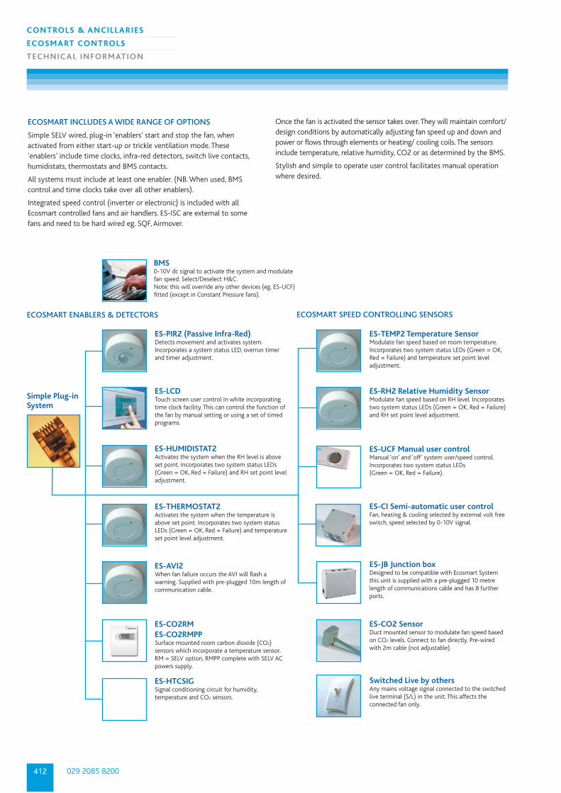
ES-PIR2 (Passive Infra-Red)Detects movement and activates system.Incorporates a system status LED, overrun timerand timer adjustment.
ES-LCDTouch screen user control in white incorporating time clock facility. This can control the function ofthe fan by manual setting or using a set of timed programs.
ES-HUMIDISTAT2Activates the system when the RH level is aboveset point. Incorporates two system status LEDs (Green = OK, Red = Failure) and RH set point level adjustment.
ES-THERMOSTAT2Activates the system when the temperature isabove set point. Incorporates two system statusLEDs (Green = OK, Red = Failure) and temperatureset point level adjustment.
ES-AVI2When fan failure occurs the AVI will flash awarning. Supplied with pre-plugged 10m length ofcommunication cable.
ES-CO2RMES-CO2RMPPSurface mounted room carbon dioxide (CO2)sensors which incorporate a temperature sensor.RM = SELV option, RMPP complete with SELV ACpowers supply.
ES-HTCSIGSignal conditioning circuit for humidity,temperature and CO2 sensors.
ES-TEMP2 Temperature SensorModulate fan speed based on room temperature. Incorporates two system status LEDs (Green = OK,Red = Failure) and temperature set point level adjustment.
ES-RH2 Relative Humidity SensorModulate fan speed based on RH level. Incorporatestwo system status LEDs (Green = OK, Red = Failure)and RH set point level adjustment.
ES-UCF Manual user control Manual ‘on’ and ‘off’ system user/speed control. Incorporates two system status LEDs (Green = OK, Red = Failure).
ES-CI Semi-automatic user controlFan, heating & cooling selected by external volt freeswitch, speed selected by 0-10V signal.
ES-JB Junction boxDesigned to be compatible with Ecosmart Systemthis unit is supplied with a pre-plugged 10 metrelength of communications cable and has 8 furtherports.
ES-CO2 SensorDuct mounted sensor to modulate fan speed based on CO2 levels. Connect to fan directly. Pre-wiredwith 2m cable (not adjustable).
Switched Live by othersAny mains voltage signal connected to the switchedlive terminal (S/L) in the unit. This affects theconnected fan only.
ECOSMART INCLUDES A WIDE RANGE OF OPTIONS
Simple SELV wired, plug-in ‘enablers’ start and stop the fan, whenactivated from either start-up or trickle ventilation mode. These‘enablers’ include time clocks, infra-red detectors, switch live contacts,humidistats, thermostats and BMS contacts.
All systems must include at least one enabler. (NB. When used, BMScontrol and time clocks take over all other enablers).
Integrated speed control (inverter or electronic) is included with allEcosmart controlled fans and air handlers. ES-ISC are external to somefans and need to be hard wired eg. SQF, Airmover.
Once the fan is activated the sensor takes over. They will maintain comfort/design conditions by automatically adjusting fan speed up and down andpower or flows through elements or heating/ cooling coils. The sensorsinclude temperature, relative humidity, CO2 or as determined by the BMS.
Stylish and simple to operate user control facilitates manual operationwhere desired.
ECOSMART ENABLERS & DETECTORS ECOSMART SPEED CONTROLLING SENSORS
Simple Plug-inSystem
BMS0-10V dc signal to activate the system and modulatefan speed. Select/Deselect H&C.Note: this will override any other devices (eg. ES-UCF)fitted (except in Constant Pressure fans).

413
CONTROLS & ANCILLARIES
ECOSMART CONTROLS
TECHNIC AL INFORMATION
nuaire.co.ukDownload specification from www.nuaire.co.uk/specifications
ECOSMART, BMS AND COMMISSIONING CONTROL OPTIONS
Nuaire fans and Air Handling Units can be provided with the following pre-
selected control options, simply and easily by adding letters to the end of the
fan code, there is no need to select or specify the controls individually if one
of these options are chosen :
ES Ecosmart controls The compact Ecosmart control module comes complete with a factoryfitted Ecosmart PCB which will control the fan unit within the desireddesign parameters and provide the interface between all external controldevices detailed on these pages.
The Ecosmart control module has the following energy savingcomponents integrally mounted, pre-wired to interface with the purposemade PCB, all components pre-wired, configured and factory fitted bythe manufacturer: (Not pre-wired to eg. SQF, Airmover).
• Integral Frequency inverter/speed controller.
• Integral maximum and minimum speed adjustment for commissioning.
• Integral adjustable run on timer.
• Integral BMS interfaces - 0- 10V speed adjustment.
• Integral BMS interfaces - Volt free failure and status indication.
• Integral background ventilation switch (trickle switch).
• Multiple IDC sockets for interconnection of sensors or fans using pre-plugged 4-core low voltage cable.
• Pre-programmed with soft start function
SET UP/COMMISSIONING BOX
The Ecosmart control module has the following two options fitted as standard.
BMS interfaces
The Ecosmart control module can be pre-configured to provide thefollowing integrated BMS interfaces.
• 0 - 10 volt input to provide a full BMS interface. This will enable thefollowing functions:-Switch the unit ON/OFF.Switch heating or cooling ON/OFF (AHUS with relevant coils).Switch from low speed to high speed - variable.Switch from low speed to high speed - trickle and boost principle.Full speed control facility.
• 2 No. Volt free contacts to provide fan run and failure indication to provide system status.
• An integrated commissioning/speed control to accurately commissionthe system, with minimum and maximum speeds easily adjusted via aminiature dial, as recommended in Part L. This will enable the unit to beconfigured to run between set parameters thus saving motor powerand limiting noise.
• Pre-programmed with soft start function.
COMMISSIONING SET UP
The Ecosmart control module can be pre-configured to provide the following integrated commissioning features only.
• Integrated commissioning/speed control to accurately commission thesystem, as recommended in Part L, This will enable the unit to beconfigured to run between set parameters thus saving motor powerand limiting noise.
• Minimum and max speeds easily adjusted via miniature dial. Thecommissioning set up facility directly controls the integrated speedcontrol/frequency inverter.
• Pre-programmed with soft start function
ENABLING SENSOR
ES-PIR2 Sensor The sensor operates with Safe Extra Low Voltage (SELV) with powersupplied from the fan unit via the communications cable. The ES-PIRsensor will activate the system when movement is detected. Anadjustable 1-60 minute timer is incorporated to provide a run on facility.Up to 10m directly in front of lens and up to 2m at 40º to the lens axis.
When adjustments are made to the sensor, the LED light on the sensorfront will flash on and off to show the set point. First, green flashes willindicate the set point in TENS, then red flashes will indicate UNITS. For example 1 green flash and 5 red flashes show you that the PIR timeris set to fifteen minutes.
ES-Thermostat2The ES-Thermostat will enable the fan when the ambient temperature is1ºC above the set point and will stop the fan when the temperature is ator below set point. The sensor operates with Safe Extra Low Voltage (SELV) withpower supplied from the fan unit via the communications cable. Adjustingthe sensor set points. Adjustable temperature setting 10 - 35ºC.
After adjustments are made to the sensor, the LED light on the sensorfront will flash on and off to show the set point. First, green flashes willindicate the set point in TENS, then red flashes will indicate UNITS. For example 2 green flashes and 3 red flashes show a temperature setpoint of 23ºC.
N
NET
Fan 2 Fan 10V
0-10V
Run
Run
FaultFault
Link wire
0V = No BMS0.25V = Off or Trickle0.5V = Speed 10.75V = Speed 1 & Cooling1V = Speed 1 & HeatingHeat & cool signal via NET to ES-VF
LSL
OPCLN
RET
240V 1 ph 50Hz*Sensor
*Not included as standard.
Switch live signal 100-230VDamper Open 230V 1A
Close 230V 1A
Return 230V signal
Contacts Volt Free Run & Fail
Neutral
0-10V BMS Signal
F3 F4
Ecosmart Control Device
Important: The Fan will not control external Heating/cooling equipment, will only provide ON/OFF Signal
MIN =
MAX =
SL Run on =
TRICKLE =
TEST =
LED indicators
Min Max SL run on
Trickle Test
0 1
Pwr
Standby
Fan 1
Fan 2
Heating
Cooling
Fault
Frost
Tx
Rx
Minimum speed adjustmentMaximum speed adjustmentSwitched Live Run-On Timer adjustmentSelects trickle running:
0 = off, 1 = selectedTest button

029 2085 8200414
CONTROLS & ANCILLARIES
ECOSMART CONTROLS
TECHNIC AL INFORMATION
ES-Humidistat2The ES-Humidistat will enable the Ecosmart fan when the measuredhumidity level is 2% above the set point and will stop the fan when thehumidity is at or below set point. The sensor operates with Safe ExtraLow Voltage (SELV) with power supplied from the fan unit via thecommunications cable. Adjusting the sensor set points - Adjustable RHsetting 65 - 85%.
After adjustments are made to the sensor, the LED light on the sensorwill flash indicating via a small aperture on the side of the sensor the setpoint. First, green flashes will indicate the set point in TENS, then redflashes will indicate UNITS. For example 7 green flashes and 3 red flashesshow a RH set point of 73%.
SPEED CONTROLLING DEVICES
ES-RH2 Humidity SensorThe ES-RH Sensor will vary the ventilation rate automatically accordingto the measured humidity. Voltage (SELV) with power supplied from thefan unit via the communications cable. The sensor has an adjustable 65-85% RH set point.
After adjustments are made to the sensor, the LED light on the sensorfront will flash on and off to show the set point. First, green flashes willindicate the set point in TENS, then red flashes will indicate UNITS. For example 7 green flashes and 5 red flashes show a set point of 75% RH.Note: fan speed = 0 (i.e. off) at or below the set point.
ES-TEMP2This will modulate fan speed based on room temperature. The sensoroperates with Safe Extra Low Voltage (SELV) with power supplied fromthe fan unit via the communications cable.
After adjustments are made to the sensor, the LED light on the sensorfront will flash on and off to show the set point. First, green flashes willindicate the set point in TENS, then red flashes will indicate UNITS. For example 2 green flashes and 3 red flashes show a temperature setpoint of 23ºC.Note: fan speed = 0 (i.e. off) at or below the set point.
Sensor Response - Normal operation (Proportional band over ten 10ºC steps)When temperature RISES, the fans will increase speed. (See above) whichshows a set point at 19ºC. For single phase fans, the speed steps areapproximate and actual running speeds will be dictated by the operatingpressure of the system and the type of impeller used in the blower. Fan isswitched off at set point unless the trickle switch is selected.
ES-CO2 Carbon Dioxide Sensor - Operation
The CO2 Sensor will adjust the fan speed in response to the CO2
concentration in the airflow.The fan speed is divided into 10 steps fromminimum (step 1) to maximum (step 10). See table below for responsedetails.
Speed 1 2 3 4 5 6 7 8 9 10
CO2 PPM 502 580 659 737 834 902 980 1059 1137 1215
ES-LCD (Time clock included)The ES-LCD Time clock will switch the system on and off at pre-determined times set by the user. This digital time clock will override the user control for effective on/off operation or any other enabling device eg. PIR. The time clock operates on Safe Extra Low Voltage and is powered from the fan control module. The connection is made into any ‘NET’ socket on the fans integral control module. See I&M for further details.
ES-LCD includes:Ventilation, Automatic Heating & Cooling Enable/Disable. Temperature is set at main control of unit.
ES-CI (Ecosmart controlinterface)
Enables any Ecosmart unit to be controlled via any remote non Ecosmartswitching device or item of plant.
Connect to fan via 4-core data cable
STATUS
PWR
Fan Heat Cool
(B) Switch to selectmax or min speed
(A) O- IOV signal to selectfan speed only
Volt free contacts to select heatingand cooling operations
Volt free contact to switch on fan
OV
O -
IOV
Min
Sele
ctM
ax
415
CONTROLS & ANCILLARIES
ECOSMART CONTROLS
TECHNIC AL INFORMATION
nuaire.co.ukDownload specification from www.nuaire.co.uk/specifications
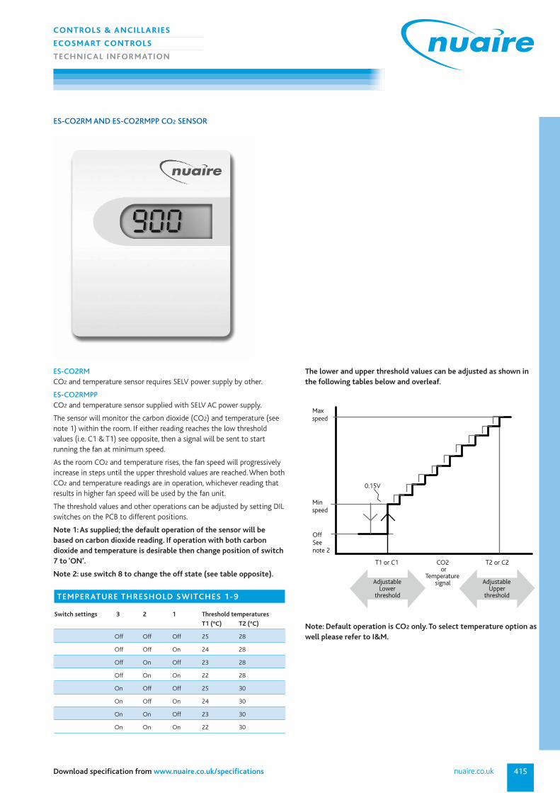
ES-CO2RMCO2 and temperature sensor requires SELV power supply by other.
ES-CO2RMPPCO2 and temperature sensor supplied with SELV AC power supply.
The sensor will monitor the carbon dioxide (CO2) and temperature (seenote 1) within the room. If either reading reaches the low thresholdvalues (i.e. C1 & T1) see opposite, then a signal will be sent to startrunning the fan at minimum speed.
As the room CO2 and temperature rises, the fan speed will progressivelyincrease in steps until the upper threshold values are reached. When bothCO2 and temperature readings are in operation, whichever reading thatresults in higher fan speed will be used by the fan unit.
The threshold values and other operations can be adjusted by setting DILswitches on the PCB to different positions.
Note 1: As supplied; the default operation of the sensor will bebased on carbon dioxide reading. If operation with both carbondioxide and temperature is desirable then change position of switch7 to ‘ON’.
Note 2: use switch 8 to change the off state (see table opposite).
The lower and upper threshold values can be adjusted as shown inthe following tables below and overleaf.
ES-CO2RM AND ES-CO2RMPP CO2 SENSOR
Max speed
Minspeed
OffSee note 2
0.15V
T1 or C1 CO2 T2 or C2 or Temperature signalAdjustable
Lower threshold
AdjustableUpper
thresholdTEMPERATURE THRESHOLD SWITCHES 1-9
Switch settings 3 2 1 Threshold temperatures
T1 (ºC) T2 (ºC)
Off Off Off 25 28
Off Off On 24 28
Off On Off 23 28
Off On On 22 28
On Off Off 25 30
On Off On 24 30
On On Off 23 30
On On On 22 30
Note: Default operation is CO2 only. To select temperature option aswell please refer to I&M.
029 2085 8200416
CONTROLS & ANCILLARIES
ECOSMART CONTROLS
TECHNIC AL INFORMATION
BMS
com
pati
ble
Co
mm
issi
oni
ng c
ont
rol
Run
/Fai
l sig
nal (
volt
fre
e)
Inve
rter
co
ntro
l (3
phas
e)
Spee
d co
ntro
l (si
ngle
pha
se)
Pre-
pipe
d co
il (c
/w D
RV)
Mo
tori
sed
cont
rol v
alve
(c/
w a
ctua
tor)
Air
off
Tem
p st
at
Fro
st p
rote
ctio
n
Hea
t di
ssip
atio
n ru
n o
n
Plug
in s
enso
rs (
see
over
leaf
)
Tric
kle
and
Boo
st s
wit
ch
Aut
om
atic
Byp
ass
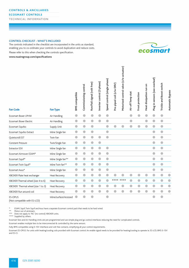
CONTROL CHECKLIST - WHAT’S INCLUDEDThe controls indicated in the checklist are incorporated in the units as standard,enabling you to co-ordinate your controls to avoid duplication and reduce costs.
Please refer to this when checking the controls specification.
www.nuairegroup.com/specifications
Fan Code Fan Type
Ecosmart Boxer LPHW Air Handling ● ● ● ● ● ● ● ● ● ●
Ecosmart Boxer Electric Air Handling ● ● ● ● ● ● ● ● ●
Ecosmart Squrbo Supply Unit ● ● ● ● ● ● ● ● ● ● ●
Ecosmart Squrbo Extract Inline Single fan ● ● ● ● ● ●
Quietscroll EST Twin Fan ● ● ● ● ● ● ●
Constant Pressure Twin/Single Fan ● ● ● ● ● ●
Extractor ESX Inline Single fan ● ● ● ● ● ● ●
Ecosmart Airmover ESAM* Inline Single fan ● ● ● ● ● ● ●
Ecosmart Squif* Inline Single fan** ● ● ● ● ● ● ●
Ecosmart Twin Squif* Inline Twin fan** ● ● ● ● ● ● ●
Ecosmart Axus* Inline Single fan ● ● ● ● ● ● ●
XBOXER Plate heat exchanger Heat Recovery ● ● ● ● ● ● ● ● ● ● ● ● ●
XBOXER Thermal wheel (size 4 to 6) Heat Recovery ● ● ● ● ● **** **** ● ● ● ● ● ●
XBOXER Thermal wheel (size 1 to 3) Heat Recovery ● ● ● ● ● ● ● ● ● ● ● ● ●
XBOXER Run around coil Heat Recovery ● ● ● ● ● ● ● ● ● ● ● ● ●
ES-OPUS Inline/surface/recessed ● ● ● ● ● ●(Not compatible with ES-LCD)
* ESAM, Squif, Twin Squif and Axus have a separate Ecosmart control pack that needs to be hard wired. ** Motor out of airstream. *** Does not apply to 'NC' (no control) XBOXER units. **** Supplied by others.
Ecosmart fans and Air Handling Units are pre-programmed and use simple plug and go control interfaces reducing the need for complicated controls.
Ecosmart enables multiple fans to be interconnected & controlled by the same sensors.
Fully BMS compatible using 0-10V interfaces and volt free contacts, simplifying all your control requirements.
Ecosmart ES-OPUS. For units with heating/cooling coils provided with Ecosmart control. An enable signal needs to be provided for heating/cooling to operate ie. ES-LCD, BMS 0-10Vand ES-CI.
417
CONTROLS & ANCILLARIES
ECOSMART INVERTER SPEED CONTROL
TECHNIC AL INFORMATION
nuaire.co.ukDownload specification from www.nuaire.co.uk/specifications
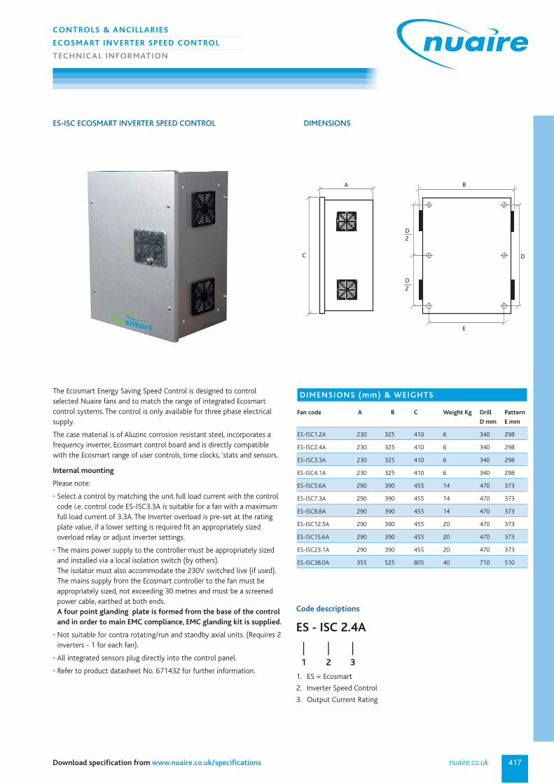
ES-ISC ECOSMART INVERTER SPEED CONTROL
Code descriptions
1. ES = Ecosmart
2. Inverter Speed Control
3. Output Current Rating
ES - ISC 2.4A
| | |1 2 3
DIMENSIONS (mm) & WEIGHTS
Fan code A B C Weight Kg Drill Pattern
D mm E mm
ES-ISC1.2A 230 325 410 6 340 298
ES-ISC2.4A 230 325 410 6 340 298
ES-ISC3.3A 230 325 410 6 340 298
ES-ISC4.1A 230 325 410 6 340 298
ES-ISC5.6A 290 390 455 14 470 373
ES-ISC7.3A 290 390 455 14 470 373
ES-ISC8.8A 290 390 455 14 470 373
ES-ISC12.5A 290 390 455 20 470 373
ES-ISC15.6A 290 390 455 20 470 373
ES-ISC23.1A 290 390 455 20 470 373
ES-ISC38.0A 355 525 805 40 710 510
A
C
D2
D2
B
D
E
The Ecosmart Energy Saving Speed Control is designed to controlselected Nuaire fans and to match the range of integrated Ecosmartcontrol systems. The control is only available for three phase electricalsupply.
The case material is of Aluzinc corrosion resistant steel, incorporates afrequency inverter, Ecosmart control board and is directly compatible with the Ecosmart range of user controls, time clocks, ‘stats and sensors.
Internal mounting
Please note:
• Select a control by matching the unit full load current with the controlcode i.e. control code ES-ISC3.3A is suitable for a fan with a maximumfull load current of 3.3A. The Inverter overload is pre-set at the ratingplate value, if a lower setting is required fit an appropriately sizedoverload relay or adjust inverter settings.
• The mains power supply to the controller must be appropriately sizedand installed via a local isolation switch (by others). The isolator must also accommodate the 230V switched live (if used).The mains supply from the Ecosmart controller to the fan must beappropriately sized, not exceeding 30 metres and must be a screenedpower cable, earthed at both ends. A four point glanding plate is formed from the base of the controland in order to main EMC compliance, EMC glanding kit is supplied.
• Not suitable for contra rotating/run and standby axial units. (Requires 2inverters - 1 for each fan).
• All integrated sensors plug directly into the control panel.
• Refer to product datasheet No. 671432 for further information.
DIMENSIONS

029 2085 8200418
CONTROLS & ANCILLARIES
INVERTER SPEED CONTROL
TECHNIC AL INFORMATION
INVERTER SPEED CONTROL
Code descriptions
1. 3 Phase supply
2. Inverter Speed Control
3. Output Current Rating
3 ISC 1.2A
| | |1 2 3
C
A
B
Front View
These are a range of frequency inverters for controlling the speed of 3phase AC motors. Standard range are 400V 3 phase input units coveringmotor rating from 0.75kW to kW. Higher ratings and single phase inputmodels are available upon request.
The inverters are microprocessor controlled and use state of the artInsulated Gate Bipolar Transistor (IGBT) technology. This makes themreliable and versatile. A special pulse-width modulation method withselectable pulse frequency permits quiet motor operation.
Comprehensive protective functions provide excellent inverter andmotor protection.
The inverters default factory settings, is ideal for a large range of simplemotor control applications. The inverters can also be used for moreadvanced motor control applications via its comprehensive parameterlists. The inverters can be used in both ‘stand alone’ applications as wellas being integrated into ‘Automation systems’.
DIMENSIONS (MM)
Fan code Motor Kw A B C Weight Kg
3ISC1.2A 0.37 70 142 280 1.5
3ISC1.9A 0.35 70 142 280 1.5
3ISC2.4A 0.75 70 142 280 1.7
3ISC3.3A 1.1 70 142 280 1.7
3ISC4.1A 1.5 70 142 280 1.7
3ISC5.6A 2.2 70 142 280 1.7
3ISC7.3A 3 70 142 280 1.7
3ISC8.8A 4 70 142 280 1.7
3ISC12.5A 5.5 169 177 299 3.5
3ISC15.6A 7.5 169 177 299 3.5
3ISC23.1A 11 169 177 299 3.5
3ISC31.0A 15 260 177 320 5
3ISC38.0A 18.5 260 177 320 5
3ISC44.0A 22 260 177 320 5
3ISC59.0A 30 260 177 320 24
3ISC72.0A 37 260 177 320 24
3ISC87.0A 45 260 177 320 24
419
CONTROLS & ANCILLARIES
ELECTRONIC SPEED CONTROL
TECHNIC AL INFORMATION
nuaire.co.ukDownload specification from www.nuaire.co.uk/specifications
ELECTRONIC SPEED CONTROL
Code descriptions
1. Electronic Control Range Code, Single phase
2. Current Rating
NSC1 - 3A
| |1 2
DIMENSIONS
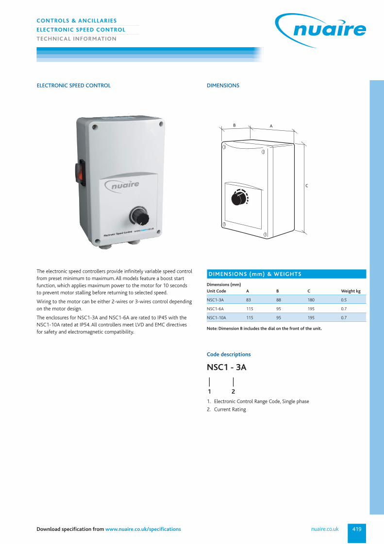
The electronic speed controllers provide infinitely variable speed controlfrom preset minimum to maximum. All models feature a boost startfunction, which applies maximum power to the motor for 10 seconds to prevent motor stalling before returning to selected speed.
Wiring to the motor can be either 2-wires or 3-wires control depending on the motor design.
The enclosures for NSC1-3A and NSC1-6A are rated to IP45 with the NSC1-10A rated at IP54. All controllers meet LVD and EMC directives for safety and electromagnetic compatibility.
DIMENSIONS (mm) & WEIGHTS
Dimensions (mm)
Unit Code A B C Weight kg
NSC1-3A 83 88 180 0.5
NSC1-6A 115 95 195 0.7
NSC1-10A 115 95 195 0.7
Note: Dimension B includes the dial on the front of the unit.
AB
C

029 2085 8200420
CONTROLS & ANCILLARIES
AUTO TRANSFORMER SPEED CONTROL
TECHNIC AL INFORMATION
SPCON AUTO TRANSFORMER SPEED CONTROL
Code descriptions
1. Single Phase
2. Transformer Speed Control
3. Current Rating
SP CON 3.5
| | |1 2 3
DIMENSIONS (mm) & WEIGHTS
Fan code A B C Weight
Single Phase kg
SPCON1.5 115 85 180 1.7
SPCON3.5 200 140 280 3.6
SPCON7.5 200 140 280 6.0
The SPCON transformer speed controllers provide either 3-step or 5-stepspeed control depending on the model.
Auto-transformers having class ‘F’ insulation are used to provide discretevoltage steps.
The 3-step models feature a power indicator, an on/off switch and aseparate 3-position rocker switch as speed selector. On the 5-stepmodels, a single rotary switch provides the on/off and speed selectionfunction.
All models are fitted with suitable fuses for short circuit protection. The controller casing is manufactured from plastic pre-coated stell orimpact resistant polycarbonate.
All models are suitable for indoor installation only. All controllers meet LVD and EMC directives for safety and electromagnetic compatibility.
Transformer speed controls produce a pure sine wave output resulting inquiet motor operation. Transformer controls are therefore preferred fornoise sensitive applications.
DIMENSIONS
AB
C
421
CONTROLS & ANCILLARIES
TEMPERATURE/CURRENT SENSING/RUN-ON TIMER
TECHNIC AL INFORMATION
nuaire.co.ukDownload specification from www.nuaire.co.uk/specifications
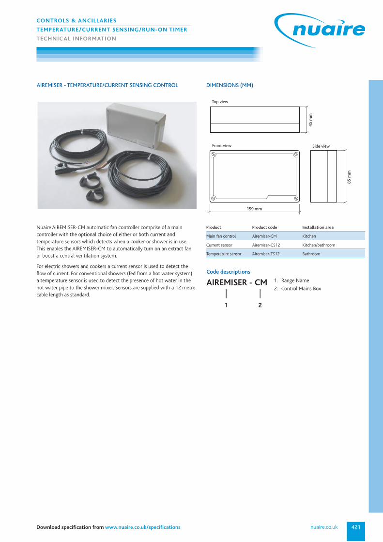
AIREMISER - TEMPERATURE/CURRENT SENSING CONTROL DIMENSIONS (MM)
Nuaire AIREMISER-CM automatic fan controller comprise of a maincontroller with the optional choice of either or both current andtemperature sensors which detects when a cooker or shower is in use. This enables the AIREMISER-CM to automatically turn on an extract fan or boost a central ventilation system.
For electric showers and cookers a current sensor is used to detect the flow of current. For conventional showers (fed from a hot water system)a temperature sensor is used to detect the presence of hot water in thehot water pipe to the shower mixer. Sensors are supplied with a 12 metrecable length as standard.
85 m
m
159 mm
45 m
m
Front view
Top view
Side view
Product Product code Installation area
Main fan control Airemiser-CM Kitchen
Current sensor Airemiser-CS12 Kitchen/bathroom
Temperature sensor Airemiser-TS12 Bathroom
Code descriptions
1. Range Name
2. Control Mains BoxAIREMISER - CM
| |1 2

029 2085 8200422
CONTROLS & ANCILLARIES
MOVEMENT DETECTION
TECHNIC AL INFORMATION
Code descriptions
1. Voltage Rating
2. Electronic Control Range Code
230 - RTIM
| |1 2
The 230-RTIM run on timer is a low cost unit designed for installationanywhere, and it’s simple to install, and use.
The box is manufactured in high impact light grey polypropylene withseven side entry grommets and a base suitable for screw fixing to anyflat surface. The timer is easily adjusted to provide between 5 and 30minutes run on. To adjust the timer, remove the lid (held by four slottedscrews) and turn the spindle to suit your run-on requirement.
The 230-RTIM run on timer is easy to wire. Simply pass a permanent230V 1 phase ‘live’ and ‘neutral’ through the SUPPLY MOTOR timer tothe fan unit and provide a switched live to operate the timer circuit.Switched live can be from any source eg. light switch, movement sensoretc. When the switched live is ‘ON’ the timer circuit is energised and thefan runs. When ‘OFF’ it provides power to the fan unit for the predetermined ‘runon’ period and then switches off the fan.
230 - RTIM RUN ON TIMER
7 X 25mm dia. cable entry grommets
110
110
65
25
DIMENSIONS (MM)

423nuaire.co.ukDownload specification from www.nuaire.co.uk/specifications
Code descriptions
CO2RM
SELV power supply (by others) must have output of24V ac (+/-20%) or 15-35V dc.
CO2RMPP
Mains supply to power must be 230V 1-50Hz.
Specifications
Current consumption Typically 10mA plus pulses of 0.3A for) .3s (every 15s)
Warm up time 5 minutes
Sensing range 0-2000ppm CO2 and 0-50ºC
Output 0-10V dc proportional output maximum load
Installed environment 0-50ºC and up to 90% RH non-condensing adjacent to fan
Maintenance Does not require routine 6 monthly intervals
Availability Next day
Warranty 3 years
230 - P.I.R. MOVEMENT DETECTOR
100mm
26mm
85mm
CARBON DIOXIDE SENSORS (C02) DIMENSIONS (MM)
86mm square
16mm
DIMENSIONS (MM)
The Passive Infra Red (P.I.R.) movement detector works by detecting the warmth of movingbodies walking through the area.
When the P.I.R. is triggered it will signal the fan or light to run. The ‘timer’ will run on for thetime set. The focusing of the unit is made up of a number of smaller lenses known as facets orzones. Each zone is focussed on a different spot to give a wide area of coverage.
The P.I.R. is triggered when walking from one zone to the next, therefore for optimumdetection sensitivity it will operate best when walking across the zone patterns.
Code descriptions
1. Voltage Rating
2. Electronic Control Range Code
3. No timer version (without NT wouldbe with timer)
230 - PIR - NT
| | |1 2 3
4 Metres max.
7.2 Metres dia.
360 Degree P.I.R Performance
Trigger Rangeapprox 6m