the metropolitan sewer district 60 01 rupture pin relief valve, section 40 91 01 transmitters,...
TRANSCRIPT

Page 1 of 1
The Metropolitan Sewer District of Greater Cincinnati
Little Miami WWTP Sludge Handling Process Upgrade
Project ID 10270080
Date Issued: 06/18/2010
ADDENDUM NO. 3
This addendum will only be distributed via e-mail, but will remain available for viewing on the MSD website at www.MSDGC.org on the project-specific web page. No hard copy will follow. Any questions you may have on the information contained in this addendum should be directed to the Project Manager, Jeffrey Dean, Project Delivery Division at 513-244-1364. NOTE: Please be sure to enter the TOTAL NUMBER of Addenda issued on the ‘Official Bid Form’ contained in the Bidding Booklet prior to submitting your bid. The attention of all bidders is directed to the following additions and/or deletions to the Contract Documents. ►ADDED ITEMS◄ ARE UNDERLINED AND DELETED ITEMS ARE STRUCK THROUGH The Contract Documents for the above referenced project are amended and revised as follows: INVITATION TO BID BOOKLET:
• ADD the following BIDDING CLARIFICATIONS: Volume II: Section 01 20 00 Measurement & Payment, Section 03 01 33 Rehabilitation of Cast- In-Place Concrete
Volume III: Section 31 20 00 Earthwork, Section 40 27 05 08 Piping Appurtenances, Section 40 29 60 01 Rupture Pin Relief Valve, Section 40 91 01 Transmitters, Section 44 02 02 Submersible Sump Pumps
• Revised David Bacon Related Act (DBRA) form • Minutes & Sign-In Sheets : • Bid Opening Date: Tuesday, June 22, 2010 Changed to Thursday, June 24, 2010. • DELETE . . . . . . (struck through) and REPLACE with . . . . . . (underline) • REPLACE the previously issued pages with the attached pages .

10270080 - Little Miami Sludge Handling Process Upgrade Addendum #3 BIDDING CLARIFICATIONS SECTION 01 11 00 SUMMARY OF PROJECT delineates division of the work among the various Contractors: Part 1 General, Part 2 Mechanical, and Part 3 electrical. The following is provided to clarify demolition: A. Part 2 – Mechanical includes all HVAC & Plumbing demolition work shown on all
the drawings which includes Boilers, Boiler Exhaust Flues, Natural Gas Piping, Hot Water Supply & Return Piping, HW Circulating Pumps, Air Handling Unit, Potable Water Piping, Fuel Oil Supply & Return Piping, Boiler Pneumatic Tank & Associated Piping, Roof Drain Piping, Roof Drains, Unit Heaters and piping, Boiler Vent Piping, Duct, Exhaust Fans, Water Heaters and Associated Piping, Sinks and Associated Piping, Showers and Associated Piping, Toilets and Associated Piping, Utility Sinks and Associated Piping, Radiators, Roof Vents, Roof Curbs, Odor Control Supply Fans, Exhaust Vents, Odor Control Piping & Supports, Hot Water Circulation Pumps, Air Handling Units, Intake Vents and Associated Appurtenances. Part 2 includes demolition of concrete bases, pads, curbs, supports, etc. associated with items demolished by the Part 2 contractor.
B. Part 3 - Electrical includes all Electrical demolition work shown on all the drawings which includes Electrical Panels, Conduit, Wiring, Wireways, Pull Boxes, Lighting, Motor Control Centers (MCC), Lighting Panels, Controls, Starters, Sump Pump Exhaust Panels & Pump Starters, Exhaust Fan Starters, Network Equipment, PLC Panels, Density Meters & Transmitters, Thickened Sludge Pump Panels, Thickened Sludge Pump Alarm Panels, Disconnects, Start/Stops, Control Panels, Level Sensors, Magnetic Flow Meters & Transmitters and Associated Appurtenances. Part 3 includes demolition of concrete bases, pads, curbs, supports, etc. associated with items demolished by the Part 3 contractor. The Part 3 – Electrical is responsible for maintenance and/or temporary electrical work to allow demolition until the new electrical work is commissioned.
C. Part 1 – General is responsible for remaining Work shown on the demolition
drawings not being performed by the Part 2 and Part 3 Contractors.
The Part 1 – General is responsible for patching all holes. The Part 1 – General is responsible for furnishing and installing the odor control duct supports shown on Sheet H-20 of 140 and as detailed on Sheet S-10 of 140. The Part 2 – Mechanical is responsible for furnishing and installing all Natural gas piping including underground installation and pavement restoration shown on Sheet C-1 of 140.

The Part 2 – Mechanical is responsible for furnishing and installing all roof drains and roof drain piping inside any building. The Part 2 – Mechanical is responsible for furnishing and installing all potable water piping and utility sinks. The Part 3 – Electrical is responsible for furnishing and installing the sump pump control panels. The 10” pipe shown to be removed on Sheet D-14 of 140 may require temporary removal of adjacent piping. Specification Section 01 45 16: The Contractor’s Quality Control Manager may be an employee of the Contractor providing he/she has the proper credentials specified. The Quality Control Manager is not required to be on site for the entire length of the project. Specification Section 44 05 13.03 is applicable to this project for all equipment with motors over 5 horsepower that are not direct coupled to the equipment. Allowances: Allowances listed on the Bid Forms should be carried over to the “Bid Item Total (Comb. X Est. Quant.)” column on the bid form. The Network Equipment Allowance (Section 25 05 00) shall be for actual equipment cost only and Contractor will not receive any markup for overhead and profit. The Contractor will be permitted 15% overhead and profit per ODOT for the Sludge Pipe Cleaning, Air Floatation Underflow Yard Piping, and Sludge Control Chamber Piping allowances. Overhead and profit is included in the allowance price. Hose Reels: Hot water pressure washer hose reels shall be as specified in Section 41 67 25. NPW hose reels shall be as shown on the Drawings. Expansion Joints: The Expansion Joint Schedule for Existing Piping on page 40 27 05.06-5 of the Specifications represents the quantity and approximate length of existing expansion joints to be replaced. These expansion joints are not shown on the Drawings. Expansion joints for new piping are not included in this schedule and shall be furnished and installed by the CONTRACTOR. DRAWINGS Sheet D-2 of 140 ADD the following to Key Note 2: “Remove locker room equipment. Remove existing floor topping per Section 03 01 33.” Sheet D-9 of 140
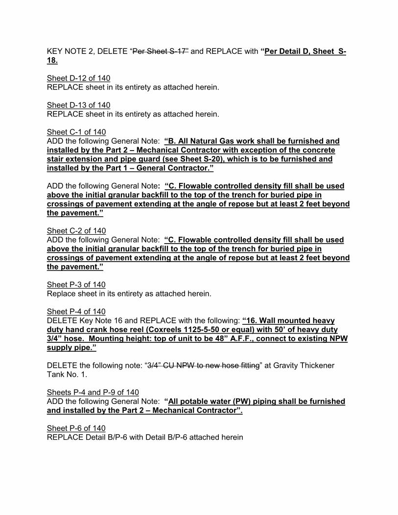
KEY NOTE 2, DELETE “Per Sheet S-17” and REPLACE with “Per Detail D, Sheet S-18. Sheet D-12 of 140 REPLACE sheet in its entirety as attached herein. Sheet D-13 of 140 REPLACE sheet in its entirety as attached herein. Sheet C-1 of 140 ADD the following General Note: “B. All Natural Gas work shall be furnished and installed by the Part 2 – Mechanical Contractor with exception of the concrete stair extension and pipe guard (see Sheet S-20), which is to be furnished and installed by the Part 1 – General Contractor.” ADD the following General Note: “C. Flowable controlled density fill shall be used above the initial granular backfill to the top of the trench for buried pipe in crossings of pavement extending at the angle of repose but at least 2 feet beyond the pavement.” Sheet C-2 of 140 ADD the following General Note: “C. Flowable controlled density fill shall be used above the initial granular backfill to the top of the trench for buried pipe in crossings of pavement extending at the angle of repose but at least 2 feet beyond the pavement.” Sheet P-3 of 140 Replace sheet in its entirety as attached herein. Sheet P-4 of 140 DELETE Key Note 16 and REPLACE with the following: “16. Wall mounted heavy duty hand crank hose reel (Coxreels 1125-5-50 or equal) with 50’ of heavy duty 3/4” hose. Mounting height: top of unit to be 48” A.F.F., connect to existing NPW supply pipe.” DELETE the following note: “3/4” CU NPW to new hose fitting” at Gravity Thickener Tank No. 1. Sheets P-4 and P-9 of 140 ADD the following General Note: “All potable water (PW) piping shall be furnished and installed by the Part 2 – Mechanical Contractor”. Sheet P-6 of 140 REPLACE Detail B/P-6 with Detail B/P-6 attached herein

Sheet P-9 of 140 DELETE Key Note 2 and REPLACE with the following: “2. Wall mounted heavy duty hand crank hose reel (Coxreels 1125-5-50 or equal) with 50’ of heavy duty 3/4” hose. Mounting height: top of unit to be 48” A.F.F., connect to existing NPW supply pipe.” Sheet P-10 of 140 Replace sheet in its entirety as attached herein. Sheet P-12 of 140 Replace sheet in its entirety as attached herein. Sheet H-3 of 140 Replace sheet in its entirety as attached herein. Sheet S-5 of 140 Replace sheet in its entirety as attached herein. TECHNICAL SPECIFICATIONS Specification Section 01 11 00 Page 01 11 00-8, Paragraph 1.13.A, ADD Item 2. as follows: “2. HVAC Permit”. Specification Section 01 14 00 Page 01 14 00-3, DELETE Paragraph 1.07.D in its entirety and REPLACE with the following: “The CONTRACTOR shall maintain passenger vehicle plant traffic and local traffic at all times during construction of this project in a manner causing the least amount of inconvenience to abutting property owners and plant traffic. Temporary Driveways, Temporary Roadways, or Turn-Arounds as may be necessary to provide passenger vehicular access shall be constructed, maintained and subsequently removed by the CONTRACTOR, as directed by the ENGINEER. The OWNER will divert sludge truck traffic for a period of no greater than 21 calendar days for construction of the Air Floatation Underflow piping and valve chambers. Passenger vehicle plant traffic must be maintained at all times.” Specification Section 01 20 00 REPLACE Section 01 20 00 in its entirety as attached herein. Specification Section 01 50 00 REPLACE Section 01 50 00 in its entirety as attached herein. Specification Section 03 01 33 REPLACE Section 03 01 33 in its entirety as attached herein.

Specification Section 22 42 00 Page 22 42 00-2, DELETE Paragraph 2.02: “2.02 HOSE REEL: Hose reels shall be Ames True Temper Model # 2388310 or equal. Reels shall be equipped with a 5/8” hose cap for use with a 5/8” garden hose. The rack shall be made of polypropylene or equal material.” Specification Section 23 74 13 Page 23 74 13-3, ADD the following to the last line of Paragraph 2.01: “Candidate manufacturers include Engineered Air, Reznor, or equal.” Specification Section 31 20 00 REPLACE Section 31 20 00 in its entirety as attached herein. Specification Section 40 27 05.08 REPLACE Section 40 27 05.08 in its entirety as attached herein. Specification Section 40 29 60.01 ADD Section 40 29 60.1 in its entirety as attached herein. Specification Section 40 91 01 REPLACE Section 40 91 01 in its entirety as attached herein. Specification Section 41 67 25 Page 41 67 25-1, Paragraph 1.01.B, DELETE “…at the pressure washer unit. Three…” and REPLACE with “…near the pressure washer unit. Two…” Specification Section 44 02 02 REPLACE Section 44 02 02 in its entirety as attached herein.

SECTION 01 20 00 MEASUREMENT AND PAYMENT PART 1 - GENERAL
1.01 SECTION INCLUDES
A. Scope.
B. General - Bidding Part 1 Bid Items by Reference Number (Ref. No.) and item description.
C. Mechanical - Bidding Part 2 Bid Items by Reference Number (Ref. No.) and item description.
D. Electrical - Bidding Part 3 Bid Items by Reference Number (Ref. No.) and item description.
E. Final Payment Considerations
1.02 RELATED DOCUMENTS
A. Drawings and general provisions of the contract, including General Conditions, Special Provisions and other Division 1 Specification Sections, apply to this Section.
1.03 SCOPE
A. CONTRACTOR shall furnish all labor, materials, tools, equipment, appurtenances and services, including operation and maintenance manuals and training and start-up services necessary to perform all work required, at the lump sum or unit prices for the items listed herein and such lump sum and unit prices shall represent full compensation for such work.
B. The bid items listed herein constitute all of the Items under which payment will be made. No direct or separate payment will be made for providing miscellaneous temporary or accessory works, plant services, layout surveys, job signs, sanitary requirements, testing safety devices, approval and record drawings, water supplies, power, maintaining traffic, removal of waste, watchmen, bonds (except Performance Bond), insurance, project coordination and all other requirements of the Contract Documents. Compensation for all such services and materials shall be included in the prices stipulated for the lump sum and unit price Items listed herein.
C. Furthermore, all work shown on the Drawings shall be a part of this contract whether specifically noted elsewhere in Contract Documents or not.
MSD ID No. 10270080 01 20 00-1 Measurement and Payment

1.04 GENERAL - BIDDING PART 1 BID ITEMS BY REFERENCE NUMBER (REF. NO.) AND ITEM DESCRIPTION
A. (Ref. No. 1) SPCL – General Construction. This item includes the completion of all General Construction Work required by Part 1 as shown on the Drawings and in accordance with all Sections under Divisions 1 (as it relates to General Construction Work), 2 through 46 together with all appurtenances. Payment will be made based on the lump sum price Bid.
B. (Ref. No. 2) SPCL – Performance Bond: The CONTRACTOR shall not include the cost of his/her Performance Bond in the Proposal. The cost entered in the Proposal should not exceed one percent of the official total bid price. This item shall be included for payment on the first partial estimate. In the event the cost entered in the Proposal exceeds one percent, all costs over the one percent will be paid with the Final Payment.
C. (Ref. No. 3) 33 01 30.16 - Sludge Pipe Cleaning Allowance: The CONTRACTOR shall include the cost shown on the Bid Form as an allowance. The allowance shall be used for additional pipe cleaning as directed by the OWNER. The allowance shall be used at the sole discretion of the OWNER. Any allowance cost not used will be deducted from the Work at project completion.
D. (Ref. No. 4) 40 27 05 - Air Floatation Underflow Yard Piping Allowance: The CONTRACTOR shall include the cost shown on the Bid Form as an allowance. The allowance shall be used for additional yard piping work as directed by the OWNER. The allowance shall be used at the sole discretion of the OWNER. Any allowance cost not used will be deducted from the Work at project completion.
E. (Ref. No. 5) 40 27 05 - Sludge Control Chamber Piping Allowance: The CONTRACTOR shall include the cost shown on the Bid Form as an allowance. The allowance shall be used for additional work in the Sludge Control Chamber as directed by the OWNER. The allowance shall be used at the sole discretion of the OWNER. Any allowance cost not used will be deducted from the Work at project completion.
1.05 MECHANICAL - BIDDING PART 2 BID ITEMS BY REFERENCE NUMBER (REF. NO.) AND ITEM DESCRIPTION
A. (Ref No. 1) SPCL – HVAC, Plumbing, and Mechanical Work: This item includes the completion of all HVAC, Plumbing, and Mechanical Work required by Part 2 as shown on the Drawings and in accordance with all Sections under Divisions 1 (as it relates to HVAC, Plumbing, and Mechanical Work), 2 through 46 together with all appurtenances. Payment will be made based on the lump sum price Bid.
B. (Ref No. 2) SPCL – Performance Bond: The CONTRACTOR shall include the cost of his/her Performance Bond in the Proposal. The cost entered in the Proposal should not exceed one percent of the official total bid price. This item shall be included for payment on the first partial estimate. In the event the cost entered in the Proposal exceeds one percent, all costs over the one percent will be paid with the Final Payment.
MSD ID No. 10270080 01 20 00-2 Measurement and Payment

MSD ID No. 10270080 01 20 00-3 Measurement and Payment
1.06 ELECTRICAL - BIDDING PART 3 BID ITEMS BY REFERENCE NUMBER (REF. NO.) AND ITEM DESCRIPTION
A. (Ref No. 1) SPCL – Electrical Work: This item includes the completion of all Electrical Work required by Part 3 as shown on the Drawings and in accordance with all Sections under Divisions 1 (as it relates to electrical Work), 2 through 46 together with all appurtenances. Payment will be made based on the lump sum price Bid.
B. (Ref No. 2) SPCL – Performance Bond: The CONTRACTOR shall include the cost of his/her Performance Bond in the Proposal. The cost entered in the Proposal should not exceed one percent of the official total bid price. This item shall be included for payment on the first partial estimate. In the event the cost entered in the Proposal exceeds one percent, all costs over the one percent will be paid with the Final Payment.
C. (Ref No. 3) 25 05 00 – Network Equipment Allowance: The CONTRACTOR shall include the cost shown on the Bid Form as an allowance. The allowance shall be used for the purchase of network equipment as directed by the OWNER. The allowance shall be used at the sole discretion of the OWNER. Any allowance cost not used will be deducted from the Work at project completion
1.07 FINAL PAYMENT
A. Comply with the requirements for Final Payment contained in Article 14.07 of the standard General Conditions.
B. Before final payment is made to the CONTRACTOR, the CONTRACTOR shall submit to the ENGINEER a release, in writing, from all the property owners whose property has been used by the CONTRACTOR outside the limits of construction and/or Right-of-Way.
PART 2 - PRODUCTS
NOT USED PART 3 - EXECUTION
3.01 TYPICAL BID ITEMS
A. Comply with the requirements for Final Payment contained in Article 14.07 of the standard General Conditions.
END OF SECTION 01 20 00

SECTION 01 50 00
TEMPORARY FACILITIES PART 1 - GENERAL
1.01 SECTION INCLUDES
A. Scope.
B. Temporary Light and Power.
C. Maintenance.
D. Temporary Heat.
E. Weather Protection.
F. Temporary Air, Steam and Water.
G. Temporary Sanitary Facilities.
H. Fire Extinguishers.
I. Office
J. Telephone
K. Project Sign.
1.02 RELATED SECTIONS
A. Drawings and general provisions of the contract, including General Conditions, Special Provisions and other Division 1 Specification Sections, apply to this Section.
1.03 SCOPE
A. CONTRACTOR’s temporary offices shall be established on the job site where approved or directed by the OWNER, adequately furnished, and maintained in a clean, orderly condition by the CONTRACTOR. The CONTRACTOR or an authorized representative shall be present in the field office at all times while work is in progress. Instructions received there from the OWNER shall be considered as delivered to the CONTRACTOR.
B. The CONTRACTOR is responsible for establishing utilities, including power, phone, and Internet access if necessary.
MSD ID No. 10270080 01 50 00-1 Temporary Facilities

MSD ID No. 10270080 01 50 00-2 Temporary Facilities
1.04 TEMPORARY LIGHT AND POWER
A. The CONTRACTOR shall provide connections to existing facilities sized to provide service required for power and lighting.
B. Where adequate electric service and lighting from OWNER facilities is not available or adequate for CONTRACTOR needs, the CONTRACTOR shall furnish temporary light and power, including 220 Volt service for welding, complete with wiring, lamps and similar equipment as required to adequately light all work areas and with sufficient power capacity to meet the reasonable needs of all subcontractors. Make all necessary arrangements with the local electric company for temporary electric service and pay all expenses in connection therewith.
C. The CONTRACTOR shall install circuit(s) and branch wiring with area distribution boxes located so that power and lighting is available throughout the site by use of construction type power cords where existing plant service is not available or where lighting is necessary.
D. The CONTRACTOR shall provide properly configured NEMA polarized outlets to prevent insertion of 110-120 Volt plugs into higher voltage outlets. For connection of power tools and equipment, provide outlets equipped with ground-fault circuit interrupters, reset button and pilot light.
E. The CONTRACTOR shall provide grounded extension cords. Use "hard-service" cords where exposed to abrasion and traffic. Provide waterproof connectors to connect separate lengths of electric cords if more than one length is required.
F. The CONTRACTOR shall provide general service incandescent lamps as required for adequate illumination where necessary. Provide guard cages or tempered glass enclosures where exposed to breakage. Provide exterior fixtures where exposed to moisture.
1.05 WEATHER PROTECTION
A. The CONTRACTOR shall furnish, install and maintain temporary heat and enclosures to provide adequate working areas for Plant personnel and to protect equipment, piping, and facilities during the months of November through March.
B. The CONTRACTOR shall furnish temporary heating units that shall have been tested and labeled by UL, FM, or other recognized association related to the type of fuel being used, and maintain reasonable temperatures within the temporary enclosures.
1.06 TEMPORARY AIR, STEAM AND WATER
A. The CONTRACTOR shall provide all air, steam and water, including temporary piping and appurtenances required for cleaning and testing pipelines and equipment. Remove

MSD ID No. 10270080 01 50 00-3 Temporary Facilities
temporary piping and appurtenances upon approval of equipment being tested.
1.07 TEMPORARY SANITARY FACILITIES
A. The CONTRACTOR shall provide self-contained, single occupant toilet units of the chemical, aerated recirculation, or combustion type, properly vented and fully enclosed in a fiberglass or other approved non-absorbent shell.
B. The CONTRACTOR is responsible for maintaining temporary sanitary facilities, including coordinating and paying for periodic disposal of contents, and removing it at Final Completion.
1.08 FIRE EXTINGUISHERS
A. The CONTRACTOR shall provide portable UL-rated, Class A fire extinguishers for temporary offices and similar spaces. In other locations, provide portable UL-rated Class ABC dry chemical extinguishers or a combination of NFPA recommended Classes for the exposure. Comply with NFPA 10 and 241 for classification, extinguishing agent and size required by location and class of fire exposure.
1.09 OFFICE
A. The CONTRACTOR shall maintain a suitable office at the site of the work.
B. CONTRACTOR’s Office 1. Provide a weathertight office of sufficient size and facilities to
accommodate CONTRACTOR’s field personnel, his Subcontractors, job meetings, storage of field documents, layout space for Drawings, drafting table for production of As-Built Drawings.
C. ENGINEER’s Office 1. Portable or mobile building, constructed with floors raised above ground
with steps and landing for entrance doors. Minimum ceiling height of 7 feet. Minimum 200 square feet with minimum dimension of 8 feet. Provide a separate entrance. If attached to other facilities, soundproof common walls.
2. The office must be installed and ready for use no more than 14 days after receipt of signed Contract. The office location must be approved by the ENGINEER.
3. Janitorial maintenance and cleaning shall be provided by the CONTRACTOR on a weekly basis minimum.
4. The following features shall minimally be included with the office. a. 100 feet candle lighting at desktop height and exterior lighting at
doors. b. Heating, cooling, and ventilation automatically controlled for 68°F
heating and 75oF cooling conditions. c. Minimum (2) windows with 10 percent of floor area with operable
sash and insect screen. d. Minimum (4) 110 volt duplex convenience outlets.
MSD ID No. 10270080 01 50 00-4 Temporary Facilities
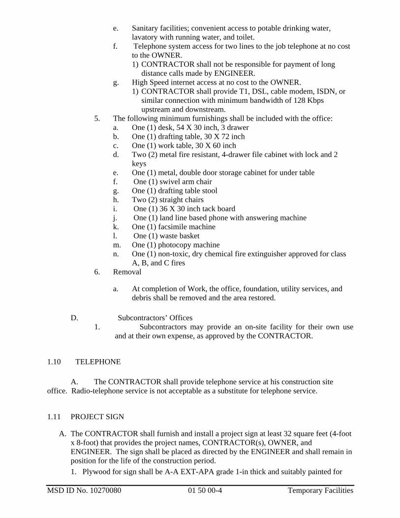
e. Sanitary facilities; convenient access to potable drinking water, lavatory with running water, and toilet.
f. Telephone system access for two lines to the job telephone at no cost to the OWNER. 1) CONTRACTOR shall not be responsible for payment of long
distance calls made by ENGINEER. g. High Speed internet access at no cost to the OWNER.
1) CONTRACTOR shall provide T1, DSL, cable modem, ISDN, or similar connection with minimum bandwidth of 128 Kbps upstream and downstream.
5. The following minimum furnishings shall be included with the office: a. One (1) desk, 54 X 30 inch, 3 drawer b. One (1) drafting table, 30 X 72 inch c. One (1) work table, 30 X 60 inch d. Two (2) metal fire resistant, 4-drawer file cabinet with lock and 2
keys e. One (1) metal, double door storage cabinet for under table f. One (1) swivel arm chair g. One (1) drafting table stool h. Two (2) straight chairs i. One (1) 36 X 30 inch tack board j. One (1) land line based phone with answering machine k. One (1) facsimile machine l. One (1) waste basket m. One (1) photocopy machine n. One (1) non-toxic, dry chemical fire extinguisher approved for class
A, B, and C fires 6. Removal
a. At completion of Work, the office, foundation, utility services, and debris shall be removed and the area restored.
D. Subcontractors’ Offices
1. Subcontractors may provide an on-site facility for their own use and at their own expense, as approved by the CONTRACTOR.
1.10 TELEPHONE A. The CONTRACTOR shall provide telephone service at his construction site office. Radio-telephone service is not acceptable as a substitute for telephone service.
1.11 PROJECT SIGN
A. The CONTRACTOR shall furnish and install a project sign at least 32 square feet (4-foot x 8-foot) that provides the project names, CONTRACTOR(s), OWNER, and ENGINEER. The sign shall be placed as directed by the ENGINEER and shall remain in position for the life of the construction period.1. Plywood for sign shall be A-A EXT-APA grade 1-in thick and suitably painted for

MSD ID No. 10270080 01 50 00-5 Temporary Facilities
exterior service for the duration of the project. Posts shall be pressure treated lumber. 2. Remove and dispose of project sign at Final Completion, unless otherwise directed.
PART 2 – PRODUCTS
NOT USED PART 3 – EXECUTION
NOT USED END OF SECTION 01 50 00

SECTION 03 01 33
REHABILITATION OF CAST-IN-PLACE CONCRETE PART 1 -- GENERAL 1.1 DESCRIPTION A. SCOPE: This section specifies a concrete mortar system for repairing of concrete surfaces and for flooring in the electrical control room. The work includes all labor, materials and services to remove the existing flooring in the locker room area and any deteriorated concrete by chipping, grinding and brushing to a depth where sound concrete is reached. The concrete mortar system shall be chemically bonded to the existing concrete. Application of the systems shall be under the supervision of the manufacturer of the system components. B. SURFACES TO BE REPAIRED:
1. Surfaces to be repaired are as shown on the contract drawings. The CONTRACTOR shall repair 600 square feet of damaged surfaces. All damaged areas of surfaces shall be repaired with the concrete mortar system so a smooth uniform surface is obtained.
2. The CONTRACTOR shall repair 350 square feet of concrete floor at the existing locker room area and adjacent floor area that will be located in the new electrical control room.
C. SERVICE CONDITIONS: The system provided under this section shall be suitable for application on vertical and overhead surfaces and exposure to temperatures ranging from 80 degrees F to 140 degrees F. 1.2 QUALITY ASSURANCE A. REFERENCES: This section contains references to the following documents. They are a part of this section as specified and modified herein. In case of conflict between the requirements of this section and those of the listed documents, the requirements of this section shall prevail.
MSD ID No. 10270080 03 01 33-1 Rehabilitation of Cast-In-Place Concrete
Reference Title
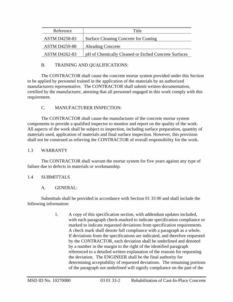
ASTM D4258-83 Surface Cleaning Concrete for Coating
ASTM D4259-88 Abrading Concrete
ASTM D4262-83 pH of Chemically Cleaned or Etched Concrete Surfaces
B. TRAINING AND QUALIFICATIONS: The CONTRACTOR shall cause the concrete mortar system provided under this Section to be applied by personnel trained in the application of the materials by an authorized manufacturers representative. The CONTRACTOR shall submit written documentation, certified by the manufacturer, attesting that all personnel engaged in this work comply with this requirement. C. MANUFACTURER INSPECTION: The CONTRACTOR shall cause the manufacturer of the concrete mortar system components to provide a qualified inspector to monitor and report on the quality of the work. All aspects of the work shall be subject to inspection, including surface preparation, quantity of materials used, application of materials and final surface inspection. However, this provision shall not be construed as relieving the CONTRACTOR of overall responsibility for the work. 1.3 WARRANTY The CONTRACTOR shall warrant the mortar system for five years against any type of failure due to defects in materials or workmanship. 1.4 SUBMITTALS A. GENERAL:
Submittals shall be provided in accordance with Section 01 33 00 and shall include the following information:
1. A copy of this specification section, with addendum updates included,
with each paragraph check-marked to indicate specification compliance or marked to indicate requested deviations from specification requirements. A check mark shall denote full compliance with a paragraph as a whole. If deviations from the specifications are indicated, and therefore requested by the CONTRACTOR, each deviation shall be underlined and denoted by a number in the margin to the right of the identified paragraph referenced to a detailed written explanation of the reasons for requesting the deviation. The ENGINEER shall be the final authority for determining acceptability of requested deviations. The remaining portions of the paragraph not underlined will signify compliance on the part of the
MSD ID No. 10270080 03 01 33-2 Rehabilitation of Cast-In-Place Concrete

CONTRACTOR with the specifications. Failure to include a copy of the marked-up specification sections, along with justification(s) for any requested deviations to the specification requirement, with the submittal shall be sufficient cause for rejection of the entire submittal with no further consideration.
2. Proposed surface preparation method.
3. Concrete mortar system materials and manufacturer's instructions,
including product safety bulletins, mixing and proportioning instructions, shelf life and storage requirements, environmental requirements for application, curing time and formulation adjustments required for job site conditions.
4. Contractors quality control plan for maintaining an even uniform finish.
5. A complete application schedule for the concrete repair systems. No work under this Section shall be performed until the required documentation has been submitted to and reviewed by the Engineer.
6. Documentation of experience for personnel to be applying the concrete
mortar system.
7. The Contractor shall submit a written warranty for the concrete systems for five years against any type of failure due to defects in materials and application.
1.5 WARRANTY The Contractor shall warrant the concrete repairs for five years against any type of failure due to defects in materials or workmanship.
PART 2--PRODUCTS 2.1 ACCEPTABLE PRODUCTS A. The concrete mortar system materials for concrete surfaces, except at the existing locker room area and adjacent floor area that will be located in the new electrical room, shall be one of the following:
1. Emaco S88 CI by BASF Construction Chemicals, Shakopee, MN
2. SikaRepair 224 by Sika Corporation, Lyndhurst, NG
3. Or equal
MSD ID No. 10270080 03 01 33-3 Rehabilitation of Cast-In-Place Concrete

B. Electrical Room Concrete Flooring: The concrete repair mortar system for the
existing locker room area and adjacent floor area that will be located in the new electrical room shall be the following:
1. Emaco R310 CI
2. Or equal
2.2 MATERIALS A. CONCRETE REPAIR MORTAR:
Repair mortar shall be a cementitious, silica fume modified, fiber reinforced, low shrinkage repair mortar, formulated for application to vertical and overhead concrete substrates by the wet-mix process shotcrete equipment or low pressure spray. Repair mortar shall not be polymer-modified, shall not form a vapor barrier, and shall not contain chlorides. It shall have the following characteristics at 28 days (minimum unless otherwise indicated).
Compressive strength (ASTM C109*): 2,500 psi (1 day) 5,000 psi (7 days) 7,000 psi (28 days) Flexural strength (ASTM C348): 770 psi Tensile strength (ASTM C496): 600 psi Slant shear bond strength (ASTM C882): 3000 psi
* Specified values indicated may be multiplied by 0.85 for comparison to material properties determined by ASTM C42)
B. ELECTRICAL ROOM CONCRETE FLOORING: The flooring shall be a polymer-modified, shrinkage compensated, flowable repair mortar
with an integral corrosion inhibitor.
It shall have the following characteristics at 28 days (minimum unless otherwise indicated).
Compressive strength (ASTM C109*): 2,500 psi (1 day) 5,500 psi (7 days) 7,500 psi (28 days) Flexural strength (ASTM C348): 1500 psi Tensile strength (ASTM C496): 600 psi Slant shear bond strength (ASTM C882): 2100 psi
MSD ID No. 10270080 03 01 33-4 Rehabilitation of Cast-In-Place Concrete

PART 3-- EXECUTION 3.1 GENERAL A. All surface preparations shall be in strict accordance with the manufacturer's recommendations. B. Surfaces not to be repaired shall be protected during the cleaning, mortar repair operations. Surfaces shall be approved by the ENGINEER prior to application of mortar. Coatings shall not be applied when surface temperature is less than 5°F above the dew point of ambient air, or when weather conditions are otherwise unsuitable. C. CONTRACTOR shall provide the manufacturers inspector for each system to assist and advise the applicator in the proper methods of surface preparation, proper conditions of application, handling of materials, and use of special equipment. 3.2 MANUFACTURER QUALITY ASSURANCE All work associated with the application of the mortar system shall be inspected and approved by the manufacturer's inspector. All cost of inspection shall be borne by the CONTRACTOR, but the inspector shall report to the ENGINEER. The inspector shall be present at all times when any aspect of the mortar system work is being performed. Inspectors shall be required to specifically perform the following duties:
1. Conduct training and retraining programs, if necessary. 2. Approve methods for storage of stockpiled materials.
3. Approve concrete surface preparation prior to application of concrete repair mortar.
4. Inspect and accept application of concrete repair mortar prior to applying
any coatings over the concrete repair mortar.
5. Maintain quality control records for submission to the ENGINEER after completion of installation and testing of the mortar system.
3.3 MATERIALS DELIVERY AND STORAGE All materials shall be delivered to the job site in their original, unopened containers. Each container shall bear the manufacturer's label which shall contain all information required by applicable laws, including storage life and special directions. No materials with expiration dates within one month of the expected or actual date of application will be permitted to be incorporated into the work.
MSD ID No. 10270080 03 01 33-5 Rehabilitation of Cast-In-Place Concrete

Stored materials shall be protected from weather and excessive heat or cold. Flammable materials shall be stored separately in accordance with applicable laws. 3.4 SURFACE PREPARATION The CONTRACTOR shall be solely responsible for cleaning and preparation of the surfaces to be coated. Concrete surfaces to receive the mortar system shall be contaminate-free and shall have no dirt, dust, oil, grease, efflorescence, concrete curing agents, rust, previous coatings of any kind, crusts, fins, projections and loosely adhering materials. The surface shall be dry and have a pH above 10. Surface preparation shall be in accordance with the recommendations of the manufacturer and may include chipping and/or abrasive blasting. Abrasive blasting can be sand blasting, or water/sandblasting at the CONTRACTOR's discretion. Sand blasting grit shall be Mil-A-22262A(SH), arsenic-free, containing no free silica. Water/sandblasting in combination shall use the specified blasting material in combination. All used cleaning materials shall be properly disposed of off site by the CONTRACTOR. The cleaned surface shall be inspected by the manufacturer's inspector and written approval shall be furnished to the ENGINEER prior to proceeding with mortar system application. Tests to be performed by the inspector shall include pH, surface competence and dryness. All debris, regardless of origin, shall be removed from the area prior to beginning application of the coating system.
Additional Requirements:
a. Substrate should have a minimum amplitude of 1/8 in. (6 mm), unless more is recommended by the manufacturer. Use the most stringent requirement. Limit the size of chipping hammers to 15 lb. (6.8 kg) to reduce micro fractures.
b. Saw-cut perimeter of the area to be repaired to a minimum depth of 1/4”,
in. (3 mm). Do not cut existing steel reinforcement. c. Where reinforcing steel with active corrosion is encountered, comply with
the following:
1) Abrasive blast reinforcing steel to remove rust, scale and contaminants to achieve a white metal finish.
2) If half or greater of the diameter of the reinforcing steel is exposed,
chip out behind the reinforcing to a 3/4 in. (19 mm) minimum depth.
MSD ID No. 10270080 03 01 33-6 Rehabilitation of Cast-In-Place Concrete

MSD ID No. 10270080 03 01 33-7 Rehabilitation of Cast-In-Place Concrete
3) Splice new reinforcing steel to existing steel where corrosion has depleted the cross-section area by 25%, as directed by the Engineer.
d. Thoroughly abrade the roughened surface and exposed reinforcement to
remove all bond-inhibiting materials such as: rust, dirt, loose chips, and dust. Maintain substrate in a saturated, surface dry condition.
3.5 APPLICATION A. GENERAL No more than the amount of materials necessary for immediate application within the manufacturer’s allowable working window shall be prepared at any one time. The working window is environmentally sensitive. Proportions and equipment shall be as required by the manufacturer. Materials shall be applied using methods and equipment stipulated by the manufacturer at the recommended coverage rate. Apply a scrub coat of the repair material per the manufacturer’s recommendations. B. CONCRETE REPAIR MORTAR: Trowel concrete repair mortar over surfaces to level all floors and walls. Concrete repair mortar shall not be applied in lifts greater than 2 inches. All repair mortars shall be applied at a minimum of ¼” thick, unless the manufacturer requires a thicker minimum layer. 3.6 INSPECTION AND TESTING Upon completion of the installation, the manufacturer's inspector shall accompany the ENGINEER in a detailed inspection of the mortar and flexible epoxy polymer system. All costs arising from inspection activities shall be borne by the CONTRACTOR.
END OF SECTION 03 01 33

MSD ID No. 10270080 31 20 00-1 Earthwork
SECTION 31 20 00
EARTHWORK
PART 1--GENERAL 1.01 DESCRIPTION A. SCOPE: This section specifies earthwork which consists of excavation, filling, and disposal of excess material. B. DEFINITIONS:
1. COMPACTION: The degree of compaction is specified as percent compaction. Maximum or relative densities refer to dry soil densities obtainable at optimum moisture content.
2. EXCAVATION SLOPE: Excavation slope shall be defined as an inclined
surface formed by removing material from below existing grade. 3. EMBANKMENT SLOPE: Embankment slope shall be defined as an
inclined surface formed by placement of material above existing grade. 1.02 QUALITY ASSURANCE A. REFERENCES: This section contains references to the following documents. They are a part of this section as specified and modified. In case of conflict between the requirements of this section and the listed documents, the requirements of this section shall prevail. Unless otherwise specified, references to documents shall mean the documents in effect at the time of Advertisement for Bids or Invitation to Bid (or on the effective date of the Agreement if there were no Bids). If referenced documents have been discontinued by the issuing organization, references to those documents shall mean the replacement documents issued or otherwise identified by that organization or, if there are no replacement documents, the last version of the document before it was discontinued. Where document dates are given in the following listing, references to those documents shall mean the specific document version associated with that date, whether or not the document has been superseded by a version with a later date, discontinued or replaced.

MSD ID No. 10270080 31 20 00-2 Earthwork
Reference Title
ASTM C136 Standard Method for Sieve Analysis of Fine and Coarse Aggregates
ASTM D1556 Test Method for Density of Soil in Place by the Sand-Cone Method
ASTM D1557 Test Methods for Moisture-Density Relations of Soils and Soil-Aggregate Mixtures Using 10-lb (4.5-kg) Rammer and 18-in. (457-mm) Drop
ASTM D2419 Standard Test Method for Sand Equivalent Value of Soils and Fine Aggregate
ASTM D3017 Test Method for Moisture Content of Soil and Soil-Aggregate in Place by Nuclear Methods (Shallow Depth)
ODOT Latest Edition of ODOT Standard Specifications for Construction, with supplements.
B. TESTS: To demonstrate conformance with the specified requirements for earthwork, the CONTRACTOR shall provide the services of an independent testing laboratory to perform moisture content, gradation, compaction, and density tests during placement of backfill materials to check compliance with these specifications. CONTRACTOR shall submit the qualifications of the independent testing laboratory for approval. The testing laboratory shall perform tests as specified in Parts 2 and 3 of this section. Costs of testing laboratory services shall be borne by the CONTRACTOR. Tests shall be made by the independent testing laboratory in accordance with the following: Test Standard Procedure Moisture content ASTM D3017 Gradation ASTM C136 Density in-place ASTM D1556 Moisture-density relationships ASTM D1557
The independent testing laboratory shall perform tests as specified in this section. The ENGINEER may direct the CONTRACTOR to construct inspection trenches in compacted or consolidated backfill to determine that the CONTRACTOR has complied with these specifications.

MSD ID No. 10270080 31 20 00-3 Earthwork
1.03 SUBMITTALS The following information shall be provided in accordance with Section 01 33 00.
1. Qualifications of independent testing laboratory. 2. Results of testing by the independent testing laboratory, confirming compliance of each
fill type with the specified gradation and identifying the optimum moisture content for each fill type, when applicable. Test results shall be submitted a minimum of one week in advance of use for each type of fill material.
PART 2--MATERIALS 2.01 FILL MATERIALS A. TYPE A: Type A material shall be a clean gravel-sand mixture free from organic matter and shall conform to the following gradation:
U.S. standard sieve size Percent by weight passing 3/4 inch 100 3/8 inch 70-100 No. 4 55-100 No. 10 35-95 No. 20 20-80 No. 40 0-55 No. 100 0-2
B. TYPE B: Type B material shall be a select granular material free from organic matter and of such size and gradation that the specified compaction can be readily attained. Material shall have a sand equivalent value determined in accordance with ASTM D2419 of not less than 20 and shall conform to the following gradation:
U.S. standard sieve size Percent by weight passing 3 inch 100 2 inch 80-100 No. 4 60-100
No. 200 0-6 The coefficient of uniformity shall be 3 or greater.

MSD ID No. 10270080 31 20 00-4 Earthwork
The material may be an imported quarry waste, clean natural sand or gravel, select trench excavation or a mixture thereof. C. TYPE C: Type C material shall be unclassified material which is free from peat, wood, roots, bark, debris, garbage, rubbish or other extraneous material. The maximum size of stone shall not exceed 6 inches. If the material excavated from the site meets these requirements, it may be classified as Type C. D. TYPE D: Type D material shall be granular material commonly known as pea gravel and shall conform to the following gradation:
U.S. standard sieve size Percent by weight passing 1/4 inch 100 No. 8 0-5
E. TYPE E: Type E material shall be crushed rock commonly known as drain rock and shall conform to the following gradation:
U.S. standard sieve size Percent by weight passing 1-1/2 inch 100 3/4 inch 30-75 1/2 inch 15-55 1/4 inch 0-5
Type E material shall be composed of hard, durable, sound pieces having a specific gravity of not less than 2.65 F. TYPE F: Type F material shall be crushed rock and shall conform to the following gradation:
U.S. standard sieve size Percent by weight passing 1-1/2 inch 87-100 3/4 inch 45-90 No. 4 20-50 No. 30 6-29 No. 200 0-12
MSD ID No. 10270080 31 20 00-5 Earthwork
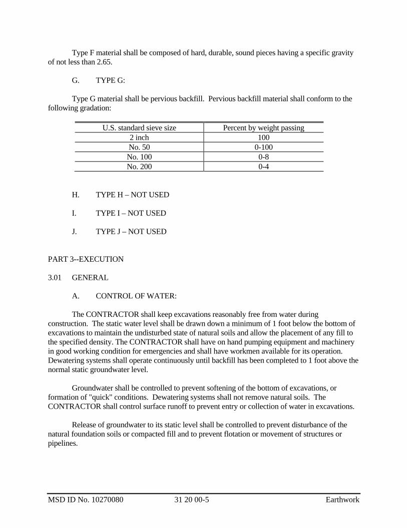
Type F material shall be composed of hard, durable, sound pieces having a specific gravity of not less than 2.65. G. TYPE G: Type G material shall be pervious backfill. Pervious backfill material shall conform to the following gradation:
U.S. standard sieve size Percent by weight passing 2 inch 100 No. 50 0-100 No. 100 0-8 No. 200 0-4
H. TYPE H – NOT USED I. TYPE I – NOT USED J. TYPE J – NOT USED PART 3--EXECUTION 3.01 GENERAL A. CONTROL OF WATER: The CONTRACTOR shall keep excavations reasonably free from water during construction. The static water level shall be drawn down a minimum of 1 foot below the bottom of excavations to maintain the undisturbed state of natural soils and allow the placement of any fill to the specified density. The CONTRACTOR shall have on hand pumping equipment and machinery in good working condition for emergencies and shall have workmen available for its operation. Dewatering systems shall operate continuously until backfill has been completed to 1 foot above the normal static groundwater level. Groundwater shall be controlled to prevent softening of the bottom of excavations, or formation of "quick" conditions. Dewatering systems shall not remove natural soils. The CONTRACTOR shall control surface runoff to prevent entry or collection of water in excavations. Release of groundwater to its static level shall be controlled to prevent disturbance of the natural foundation soils or compacted fill and to prevent flotation or movement of structures or pipelines.

MSD ID No. 10270080 31 20 00-6 Earthwork
B. OVEREXCAVATION: Where the undisturbed condition of natural soils is inadequate for support of the planned construction, the ENGINEER will direct the CONTRACTOR to overexcavate to adequate supporting soils. The excavated space shall be filled to the specified elevation with backfill. The overexcavated space under footings may be filled with concrete. The quantity and placement of such material will be paid for as extra work. C. SURPLUS MATERIAL: Unless otherwise specified, surplus excavated material shall be disposed of off site in accordance with applicable ordinances and environmental requirements. If the quantity of surplus material is specified, the quantity specified is approximate. The CONTRACTOR shall satisfy himself that there is sufficient material available for the completion of the embankments before disposing of any material inside or outside the site. Shortage of material, caused by premature disposal of any material by the CONTRACTOR, shall be replaced by the CONTRACTOR. Material shall not be stockpiled to a depth greater than 5 feet above finished grade within 25 feet of any excavation or structure except for those areas designated to be preconsolidated. For these areas, the depth of stockpiled material shall be as specified. The CONTRACTOR shall maintain stability of the soil adjacent to any excavation. D. BORROW MATERIAL: If the quantity of acceptable material from excavation is not sufficient to construct the embankments required by the work, the quantity of material needed to complete the embankments shall consist of imported borrow conforming to specified requirements. E. HAULING: When hauling is done over highways or city streets, the loads shall be trimmed and the vehicle shelf areas shall be cleaned after each loading. The loads shall be watered after trimming to eliminate dust. F. HAUL ROADS: The CONTRACTOR shall construct haul roads required to transport materials on site. Alignment of haul roads shall be selected to avoid interference with plant operations. Haul roads shall be removed after completion of embankment construction. G. FINISH GRADING: Finished surfaces shall be smooth, compacted and free from irregularities. The degree of finish shall be that normally obtainable with a blade-grader.

MSD ID No. 10270080 31 20 00-7 Earthwork
Finished grade shall be as specified by the contours plus or minus 0.10 foot except where a local change in elevation is required to match sidewalks, curbs, manholes and catch basins, or to ensure proper drainage. Allowance for topsoil and grass cover, and subbase and pavement thickness shall be made so that the specified thickness of topsoil can be applied to attain the finished grade. When the work is an intermediate stage of completion, the lines and grades shall be as specified plus or minus 0.5 foot to provide adequate drainage. If the soil is to be cultivated or straw is to be incorporated into the surface, rocks larger than 2-1/2 inches in maximum dimension, roots and other debris on the surface of the slope shall be removed and disposed of prior to cultivation or placement of straw. H. CONTROL OF EROSION: The CONTRACTOR shall maintain earthwork surfaces true and smooth and protected from erosion. Where erosion occurs, the CONTRACTOR shall provide fill or shall excavate as necessary to return earthwork surfaces to the grade and finish specified. 3.02 CLASSIFICATION OF FILL Fill material shall be placed in horizontal layers and compacted with power-operated tampers, rollers, idlers, or vibratory equipment. Material type, maximum layer depth, relative compaction, and general application are specified in Table A. Unless otherwise specified, fill classes shall be used where specified in Table A under general application.
Table A, Fill Classifications
Fill
class
Material
type
Maximum uncompressed layer depth,
inches
Minimum relative
compactionc , percent
General application
A1 A 8 95 Bedding for pipe, initial pipeline backfill; slabs on grade (other than specified for Class E1)
A2 A 48 95 Initial and subsequent pipeline backfill when ponded or jetted
B1 B 8 95 Structure and subsequent pipeline backfill
B2 B 8 90 Site fill
C1 C 8 90-95 Subsequent pipeline backfill; compaction as specified
C2 C 8 90 Site fill, embankments and dikes

MSD ID No. 10270080 31 20 00-8 Earthwork
Fill
class
Material
type
Maximum uncompressed layer depth,
inches
Minimum relative
compactionc , percent
General application
D1 D - 95 Bedding for tanks and pipe, initial and subsequent tank and pipeline backfill
E1a E 8 - Fill under slabs for structures and tank slabs with pressure relief valves
F1b F 12 95 Structure backfill, pipeline bedding, initial and subsequent pipeline backfill
G1 G 8 95 Bedding for plastic pipe, initial and subsequent pipeline backfill
aCompaction of layers shall be accomplished in two passes of equipment with complete coverage across the width of the field. bMaterial shall not be used for bedding or initial backfill for plastic pipe. cModified Proctor Density-ASTM D1557 3.03 EARTHWORK FOR STRUCTURES A. STRUCTURE EXCAVATION: The bottom shall not be more than 0.15 foot above or below the lines and grades specified. If the elevation of structure excavation is not specified, the excavation shall be not more than 0.15 foot above or below the elevation specified for fill material below the structure. Slopes shall vary no more than 0.5 foot from specified grade unless the excavation is in rock where the maximum variation shall be 2 feet. Should the excavation be carried below the lines and grades specified on the drawings or should the bottom of the excavation be disturbed because of the CONTRACTOR's operations and require overexcavation and backfill, the CONTRACTOR shall refill such excavated space to the proper elevation in accordance with the procedure specified for backfill. The cost of such work shall be borne by the CONTRACTOR. Unless otherwise specified, excavations shall extend a sufficient distance from walls and footings to allow for placing and removal of forms, installation of services, and for inspection, except where concrete is specified to be placed directly against excavated surfaces.
MSD ID No. 10270080 31 20 00-9 Earthwork
B. FOUNDATION TREATMENT: When footings are to be supported on piles, excavations shall be completed to the bottom of the footings before any piles are drilled or driven therein. When swell or subsidence results from driving piles, the CONTRACTOR shall excavate, or backfill the footing area to the grade of the bottom of the footing with suitable material as specified. If material under footings is such that it would mix into the concrete during footing placement or would not support the weight of the fluid concrete, the CONTRACTOR shall replace the material with suitable material, install soffit forms or otherwise provide a suitable platform on which to cast the footing as directed by the ENGINEER. This shall be paid for as extra work. Whenever any structure excavation is substantially completed to grade, the CONTRACTOR shall notify the ENGINEER who will make an inspection of the foundation. No concrete or masonry shall be placed until the foundation has been inspected by the ENGINEER and compacted fill has been tested by the CONTRACTOR’s independent testing laboratory to confirm compliance with the compaction specified in Paragraph 31 20 00-3.02. The CONTRACTOR shall, if directed by the ENGINEER, dig test pits and make test borings and foundation bearing tests. If the material tested is undisturbed soil, the cost thereof will be paid for as extra work. C. STRUCTURE BACKFILL: Unless otherwise specified, structure backfill shall be Class B1, including all backfill around grade beams and below slabs. The Class B1 backfill shall extend a minimum of 6’-6” below exterior slabs located at doorways. Provide a vapor barrier below interior slabs and grade beams, refer to architectural plans. All pervious backfill placed around the perimeter of the building shall terminate 1’-8” below the final grade elevation where topped with 8” of aggregate base material for parking areas. The top 1’-0” of backfill (below the aggregate base) shall consist of a cap of impervious soil such as silty sand or clay to prevent water infiltration. The impervious cap must slope away from the building to provide positive drainage away from the building. Some onsite soils may meet this criterion. All imperious soils used for final backfill shall be pre-approved for use by the Geotechnical Engineer. Do not place any impervious soils below structural elements, slabs, sidewalks or pavements. After completion of construction below the elevation of the final grade, and prior to backfilling, forms shall be removed and the excavation shall be cleaned of debris. Structure backfill shall not be placed until the subgrade portions of the structure have been inspected by the ENGINEER. No backfill material shall be deposited against concrete structures until the concrete has developed a strength of not less than 3500 pounds per square inch in compression, or until the concrete has been in place for 28 days, whichever occurs first. Backfill material shall be placed in uniform layers and shall be brought up uniformly on all sides of the structure. Unless otherwise specified, backfill around and above pipelines within the excavation line of any structure shall be the same as that specified for structures.

MSD ID No. 10270080 31 20 00-10 Earthwork
3.04 EARTHWORK FOR PIPELINES AND CONDUITS A. GENERAL: Earthwork for pipelines and conduits is specified in paragraph 31 20 00-3.02, Table A; in the standard details; and in the following paragraphs. B. PIPELINE EXCAVATION: The bottom of the trench shall be carried to the specified lines and grades with proper allowance for pipe thickness and for bedding as specified. C. PIPELINE BACKFILL:
1. BEDDING: The CONTRACTOR shall not proceed with backfill placement in excavated areas until the subgrade has been inspected by the ENGINEER. All pipe shall have a minimum thickness of bedding material below the barrel of the pipe as specified. Bedding material shall be placed in the bottom of the trench, leveled and compacted. Bell holes shall be excavated at each pipe joint to permit proper inspection and uniform bearing of pipe on bedding material.
After the pipe has been laid to alignment and grade, unless otherwise
specified, additional bedding material shall be placed in layers the full width of the trench and compacted up to the specified level. Bedding shall be placed simultaneously on both sides of the pipe, keeping the level of backfill the same on each side. The material shall be carefully placed and compacted around the pipe to ensure that the pipe barrel is completely supported and that no voids or uncompacted areas are left beneath the pipe. CONTRACTOR shall use particular care in placing material on the underside of the pipe to prevent lateral movement during backfilling.
2. INITIAL BACKFILL: After pipe has been properly bedded,
CONTRACTOR shall place and compact initial backfill as specified. Initial backfill, where specified below the springline of the pipe, shall be placed and compacted in accordance with paragraph 31 20 00-3.04 C.1 for additional bedding material.
3. SUBSEQUENT BACKFILL:
a. GENERAL: Backfill material, placement and compaction above the
pipe zone shall be as specified. Backfill above the pipe zone shall not commence until pipe zone backfill has been inspected and accepted by the ENGINEER.

MSD ID No. 10270080 31 20 00-11 Earthwork
b. IMPROVED AREAS: Unless otherwise specified, ODOT Class 5 aggregate base coarse as specified in Section 32 11 23 shall be used under all paved and unpaved roadways and paved and unpaved roadway shoulders, roadway embankments, and in all public right-of-ways and easements. The trench shall be backfilled to an elevation which will permit the placement of the specified surface or paving. Paving shall be as specified in Sections 32 12 16 and 32 13 13. Other surfaces shall be restored, including compaction, to the condition existing prior to construction including restoration of yard areas.
c. UNIMPROVED AREAS: Class C1 backfill shall be used for all
trenches in pastureland, cultivated land, undeveloped land, and for other unimproved areas where specified. Class C1 backfill shall not be used in any public right-of-way. Trench excavation which meets the requirements of Type C material may be used. The CONTRACTOR shall maximize the use of fine-grained materials (e.g., sand, silty sand, sandy silt) as Class C1 backfill.
For Class C1 backfill, the trench above the pipe zone shall be
backfilled to within 12 inches of original ground surface. The top 12 inches of soil shall be removed and stored in such a manner that it will not become mixed with unsatisfactory soils. After the trench has been backfilled, the stored topsoil shall be replaced at a uniform depth in its original area compacted to its original condition. The CONTRACTOR shall leave the backfilled trench neatly mounded not more than 6 inches above existing grade for the full width of the Class C1 backfill area. The top 8” of soil at areas to receive grass shall be topsoil, see Section 32 91 13.
4. TESTING: A minimum of 1 density test shall be performed for every 100
feet of pipe bedding placed, except for piping supported by piles. A minimum of 1 density test shall be performed for every 100 feet of subsequent backfill placed.
3.05 EARTHWORK FOR EMBANKMENTS
A. FOUNDATION PREPARATION:
The surface of the foundation shall not contain standing water and shall be free of loose material, foreign objects and rocks greater than 6 inches in maximum dimension. Immediately prior to placement of embankment fill material, the foundation surface shall be thoroughly moistened, scarified to a depth of 6 inches, moisture conditioned again as necessary and recompacted to 95 percent relative compaction. After the preparation has been completed, the CONTRACTOR shall promptly place and compact the first lift of embankment on the foundation to prevent damage to the surface. If the foundation surface is damaged, the CONTRACTOR shall repair the surface to
MSD ID No. 10270080 31 20 00-12 Earthwork
the specified condition. In any areas where materials become soft or yielding, such materials shall be removed, disposed of, and replaced with specified material. The surface of the embankment shall be maintained to permit travel of construction equipment. Ruts in the surface of any layer shall be filled and leveled before compacting. B. EMBANKMENT FILL: Rocks, broken concrete, or other solid materials, which are larger than 4 inches in greatest dimension, shall not be placed in embankment areas where piles are to be placed or driven. Fill material having a sand equivalent value less than 10 shall be placed in the lower portions of embankments and shall not be placed within 2.5 feet of finished grade. When the embankment material consists of large, rocky material, or hard lumps, such as hardpan or cemented gravel which cannot be broken readily, such material shall be well distributed throughout the embankment. Sufficient earth or other fine material shall be placed around the larger material as it is deposited so as to fill the interstices and produce a dense, compact embankment. Unless otherwise specified, the embankment shall be raised to form an approximately horizontal plane extending transversely to the final slopes. The embankment shall be crowned at all times during construction so that water will drain readily off the embankment. The temporary differential elevation between any two adjoining zones of the embankment due to construction operations shall not exceed 24 inches. If the compacted surface of any layer of material is too smooth to bond properly with the succeeding layer, the surface shall be scarified. If required, the surface shall be sprinkled or otherwise moisture conditioned before the succeeding lift is placed. Any surface crust formed on a layer of fill material that has been dumped and spread shall be broken up by harrowing and, if required, the full depth of the affected layer shall be moisture conditioned immediately prior to rolling. C. KEY CONSTRUCTION: Where specified, a key shall be excavated along the length of the toe of fill slopes. The exposed soils along the key and under fill areas shall be disced and/or scarified to a depth of at least 12 inches, moisture conditioned to within 3 percent of optimum moisture content, and compacted to at least 90 percent of maximum dry density.
MSD ID No. 10270080 31 20 00-13 Earthwork
D. EMBANKMENT TOLERANCES:
1. GENERAL: Embankment slopes within 4 feet of shoulder grade shall vary less than 0.5 foot from the designated slope. Slopes beyond 4 feet from shoulder grade shall vary less than 1 foot from the designated slope. Measurements for variance shall be made perpendicular to the slope. Slopes which are 6 to 1 or flatter shall vary less than 0.2 foot from the designated slope.
If embankments are constructed of rock greater than 12 inches in diameter,
the slopes more than 4 feet below shoulder grade may vary up to 2 feet from the designated slope.
2. ROADWAY EMBANKMENT TOLERANCES: The excavated surface
shall be less than 0.08 foot above or below the grades specified after deducting for the roadway pavement thickness.
Vertical alignment tolerances permitted on the roadway surface shall not
exceed plus or minus 0.30 feet from the vertical alignment specified, with the provision that within the tolerance range local surface irregularities shall not exceed 0.15 feet as measured by the gap between the roadway surface and a 10-foot straightedge placed on any flat graded surface. On vertical curves, the same standards will apply except that an additional gap allowance will be made for the road surface curvature over the 10-foot length of the straightedge.
Horizontal alignment tolerances permitted shall not exceed plus or minus 1
foot providing the departure is relatively uniform over any specific length of the roadway.
Roadway median strips shall be graded to drain and shall not vary more than
0.1 foot from the specified grade. E. SURCHARGE EMBANKMENT: Where shown or specified, surcharge embankment shall remain in place for the required settlement period before excavation for footings or construction of foundation piles. Surcharge embankments shall not encroach upon traveled ways nor upon existing improve-ments that are subject to damage. The CONTRACTOR shall restrain the embankment material.

MSD ID No. 10270080 31 20 00-14 Earthwork
3.06 SUBGRADE FOR PAVEMENT The prepared subgrade shall be scarified to a depth of at least 12 inches and recompacted to at least 95 percent of the maximum density. A registered geotechnical engineer shall review subgrade prior to backfill. Backfill below pavement shall be pre-approved by Geotechnical Engineer prior to placement. 3.07 SITE FILL Unless otherwise specified, site fill shall be Class C2 fill. If the existing slope in an area to be filled is greater than 5:1, the CONTRACTOR shall bench the area prior to filling.
END OF SECTION 31 20 00

SECTION 40 27 05.08
PIPING APPURTENANCES
PART 1--GENERAL 1.01 DESCRIPTION A. SCOPE: This section specifies pipeline thermometers, flow and level gages, pressure gages, strainers, steam traps, vents and drains.
B. EXCLUSIONS: Temperature, pressure and flow measuring devices used for instrumentation are specified in Division 40. PART 2--PRODUCTS 2.01 PIPELINE THERMOMETERS – NOT USED 2.02 FLOW AND LEVEL GAGES – NOT USED 2.03 PRESSURE DEVICES A. GAGE COCKS: Unless otherwise specified, gage cocks shall be Robertshaw 1303, Ashcroft 1095, or equal. The exposed threads of each gage cock shall be protected by a brass plug. B. PRESSURE GAGES: Unless otherwise specified, pressure gage scales shall be selected so that the normal operating pressure falls between 50 and 80 percent of full scale, shall be 4 1/2-inch, 270-degree movement, 1/2-percent accuracy, full-scale, and suitable for bottom stem mounting. Gages shall have a 316-SS bourdon tube. All gages shall have a 300 series stainless steel case, shatterproof glass, and a 1/2-inch NPT bottom connection.
Pressure gages for air, gas, and low pressure services (0-10 feet) shall be premium grade, heavy-duty bourdon-tube units (bellow type for vacuum) with Delrin bushings and pinion, and stainless steel sector. Gages on liquid service shall be as noted above, except they shall be provided with an internal pulsation dampening system consisting of either a glycerin fill or a silicone fluid fill.
MSD ID No. 10270080 40 27 05.08-1 Piping Appurtenances

Snubbers or orifices shall not be utilized. Gages shall be Ashcroft Duragauge Fig. 1279, Ametek 1981L, or equal.
C. DIAPHRAGM SEALS: Unless otherwise specified, seals shall be diaphragm type with 1/4-inch flushing connection, Type 316 stainless steel body and Type 316L diaphragm. Fill fluid shall be Silicone DC200 unless otherwise specified. Seal shall be Mansfield and Green Type SG, Ashcroft Type 101, or equal. D. PRESSURE SENSORS: Unless otherwise specified, pressure sensors (tubular chemical seals) shall be the in-line full stream captive sensing liquid type. Wetted parts shall be 316 stainless steel. Flexible cylinder shall be Buna-N unless otherwise specified. Seals shall be rated for 200 psi with 5-inch SC hysteresis. Seals shall be Ronningen-Petter, Red Valve, or equal. Fill fluid shall be rated for a temperature range of -20 degrees F to 200 degrees F. Capillary tubing shall be armored stainless steel. Fittings shall be provided for vacuum filling of system. Systems that are not factory filled shall be vacuum filled in the field. Filling connections shall be soldered shut after vacuum evacuation and filling. 2.04 STRAINERS A. AIR STRAINERS: Unless otherwise specified, air and gas line strainers shall be Y-pattern, cast iron body, with 40 mesh Monel screens packed with Everdur wool. Bronze bodies shall be provided with copper piping. Air line strainers shall be fitted with a brass blowoff cock. Strainers shall be Mueller, Armstrong, or equal. B. WATER AND STEAM STRAINERS: Steam and water strainers shall be of Y-pattern, unless otherwise specified. Steam strainers shall have carbon steel body; water strainers shall have cast iron body. Bronze bodies shall be provided with copper piping. Strainers shall have 304 stainless steel screens and tapped and plugged blowoff connections. Screen perforations shall be 0.020 inch for steam service and 0.045 inch for water service. Strainers shall be Mueller, Armstrong, or equal. C. BASKET STRAINERS: Basket strainers shall be cast iron or bronze, flanged, 200 PSIG construction, with removable top and lift-out perforated stainless steel baskets, equal to MUELLER Model 125F or equal. A plugged drain connection shall be included. Floor supports with bolt holes shall be provided on 4" sizes and up. 2.05 STEAM TRAPS – NOT USED
MSD ID No. 10270080 40 27 05.08-2 Piping Appurtenances

MSD ID No. 10270080 40 27 05.08-3 Piping Appurtenances
2.06 PRODUCT DATA Manufacturer’s product data shall be provided in accordance with Section 01 33 00. PART 3--EXECUTION 3.01 PIPELINE THERMOMETERS – NOT USED 3.02 GAGE TAPS Gage taps shall be provided on the suction and discharge of pumps, fans, compressors, vacuum pumps and blowers. Gage taps shall consist of a 1/4-inch gage cock attached by a threaded nipple to the pipeline, duct or equipment. 3.03 VENTS AND DRAINS Manual air vents shall be provided at the high points of each reach of pipeline where specified (refer to Section 40 27 05). Air vents shall consist of bronze cock and copper tubing return. Air vents shall be taken to the nearest floor with cock mounted 4 feet above the floor. Drains shall be piped to a sump, gutter, floor drain or other collection point with a valve mounted 4 feet above the floor. Drain valves are specified in Section 40 29 50. When drains cannot be run to collection points, they shall be routed to a point of easy access and shall have hose gate valve.
END OF SECTION 40 27 05.08

SECTION 40 29 60.01
RUPTURE PIN RELIEF VALVE PART 1--GENERAL 1.01 DESCRIPTION A. SCOPE: This section specifies overpressure relief for valves of the rupture pin type to protect Mixed Sludge Pumps 1 and 2 and Thickened Sludge Pumps 1 and 2. B. TYPE: Pressure relief valves furnished under this specification shall be of rupture pin type designed to provide overpressure relief to piping systems when their pressure is above set working pressure. Overpressure shall cause destruction of the pin. Pin shall be replaceable and valve resettable without opening the piping system. A location sensor shall be exterior to the wet side of the system and shall signal operation of the valve. C. EQUIPMENT LIST:
Item Location No.
MS-1 Rupture Pin Valve L-F-23-0037
MS-2 Rupture Pin Valve L-F-23-0040
TPS-1 Rupture Pin Valve L-F-23-0050
TPS-2 Rupture Pin Valve L-F-23-0053 D. PERFORMANCE AND DESIGN REQUIREMENTS: 1. GENERAL: The equipment specified in this section shall be suitable for continuous duty service and for exposure to fluids containing small quantities of grit and up to 3% suspended solids.
2. OPERATING REQUIREMENTS: Pressure relief design operating requirements and characteristics shall be as follows:
MSD ID No. 10270080 49 29 60.01-1 Rupture Pin Relief Valve

Rupture Pin Valve
a. Maximum flow-through valve, gpm 400
b. Diameter, inches 4
c. Maximum pressure to relieve, psig 100
d. Pressure Relief tolerance + 5%
The fluid for the relief valves will be wastewater which may contain up to 3% of particulate matter, rags, grease, and grit. 1.02 QUALITY ASSURANCE A. REFERENCES: This section contains references to the following documents. They are a part of this section as specified and modified. In case of conflict between the requirements of this section and those of the listed documents, the requirements of this section shall prevail.
Reference Title
ASTM A36-84a Structural Steel
ASTM A48-83 Gray Iron Castings
ASTM B148-86 Aluminum-Bronze Castings 1.03 SUBMITTALS
Submittals shall be provided in accordance with Section 01 33 00 and shall include the following information:
1. The qualifications of the ENGINEER to be charged with design, inspection and certification of valve supports including education, proof of registration, and previous experience in performing this type of work. The documentation shall be sufficient to demonstrate compliance with the requirements within this specification section. No further submittals under this or any related section will be considered until the qualifications of the ENGINEER have been reviewed and accepted by the ENGINEER.
2. A copy of this specification section, with addendum updates included, and all
referenced and applicable sections, with addendum updates included, with
MSD ID No. 10270080 49 29 60.01-2 Rupture Pin Relief Valve
each paragraph check-marked to indicate specification compliance or marked to indicate requested deviations from specification requirements. Check marks ( ) shall denote full compliance with a paragraph as a whole. If deviations from the specifications are indicated and, therefore requested by the CONTRACTOR, each deviation shall be underlined and denoted by a number in the margin to the right of the identified paragraph. The remaining portions of the paragraph not underlined will signify compliance on the part of the CONTRACTOR with the specifications. The submittal shall be accompanied by a detailed, written justification for each deviation. Failure to include a copy of the marked-up specification sections, along with justification(s) for any requested deviations to the specification requirements, with the submittal shall be sufficient cause for rejection of the entire submittal with no further consideration.
3. Piping layout drawings shall be transmitted to the ENGINEER a minimum of
3 weeks prior to construction. Drawings shall be original layouts by the CONTRACTOR; photocopies of contract drawings are not acceptable. Piping layout drawings shall include the location and detail for all instrumentation instruments. Requirements for each instrument shall be included and coordinated with the other Divisions.
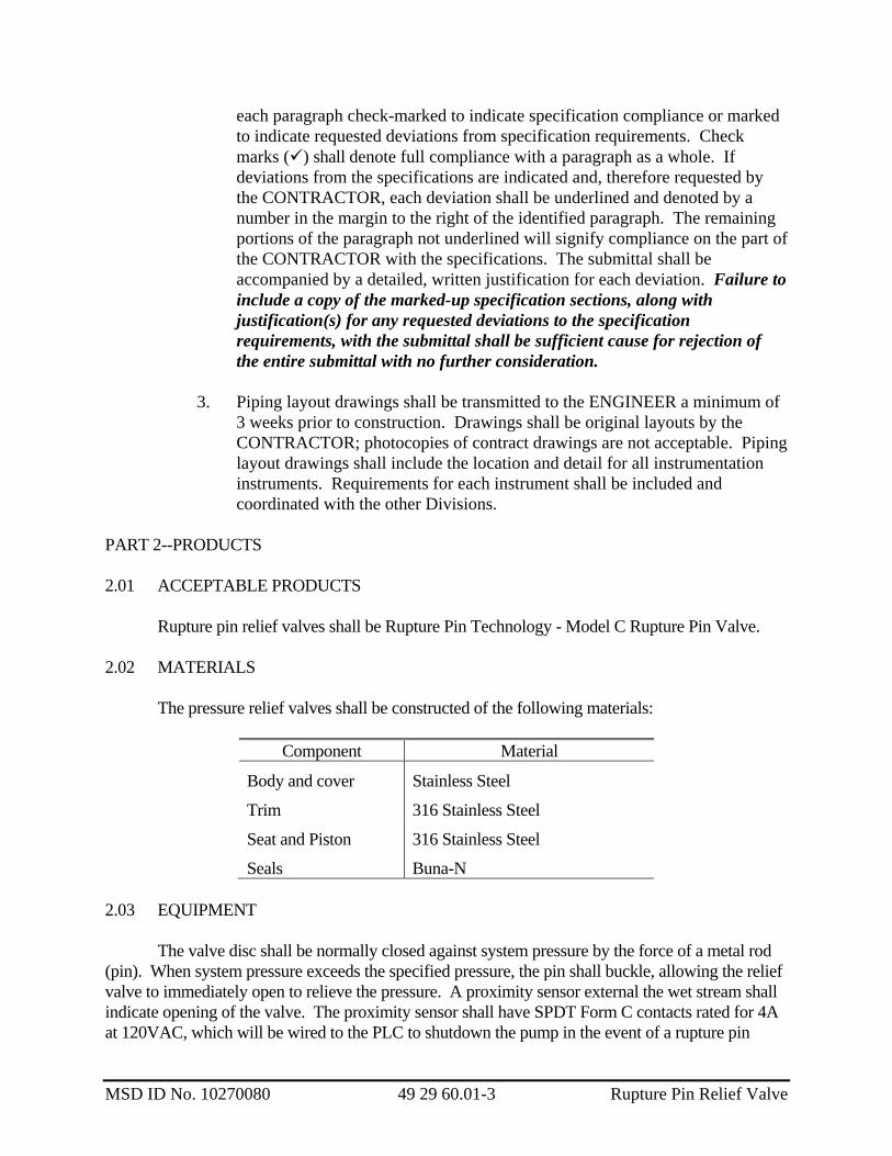
PART 2--PRODUCTS 2.01 ACCEPTABLE PRODUCTS Rupture pin relief valves shall be Rupture Pin Technology - Model C Rupture Pin Valve. 2.02 MATERIALS The pressure relief valves shall be constructed of the following materials:
Component Material
Body and cover Stainless Steel
Trim 316 Stainless Steel
Seat and Piston 316 Stainless Steel
Seals Buna-N 2.03 EQUIPMENT The valve disc shall be normally closed against system pressure by the force of a metal rod (pin). When system pressure exceeds the specified pressure, the pin shall buckle, allowing the relief valve to immediately open to relieve the pressure. A proximity sensor external the wet stream shall indicate opening of the valve. The proximity sensor shall have SPDT Form C contacts rated for 4A at 120VAC, which will be wired to the PLC to shutdown the pump in the event of a rupture pin
MSD ID No. 10270080 49 29 60.01-3 Rupture Pin Relief Valve

MSD ID No. 10270080 49 29 60.01-4 Rupture Pin Relief Valve
failure. The valve shall be manually resettable by removing the damaged pin, closing the valve and setting a new pin. Resetting the valve in no way shall require access to the wet stream. Valve shall include manufactured supplied Pin Storage at each valve. Each valve shall include 10 replacement pins. Replacement pins shall be tagged with the matching valve serial number. 2.04 PRODUCT DATA The following information shall be provided
1. Manufacturer's product data. 2. Operation and maintenance data as specified in Division 1. 3. Certified Test Reports
4. Certified Drawings.
5. Shell Test Reports
6. Seat Leak Test Results
7. Replacement Parts Ordering Information
PART 3--EXECUTION 3.01 INSTALLATION The relief valves shall be installed in the locations shown and in accordance with manufacturer's recommendations. 3.02 TESTING One of the rupture pin relief valves shall be field-tested to prove compliance with capacity and pressure drop requirements.
END OF SECTION 49 29 60.1

MSD ID No. 10270080 40 91 01-1 Transmitters
SECTION 40 91 01
TRANSMITTERS PART 1--GENERAL 1.01 DESCRIPTION
This section specifies requirements for transmitters. Application requirements are specified in Section 25 06 30. 1.02 REFERENCES
This section contains a reference to the following document. All references shall be to the current edition of the document unless specifically stated otherwise. Additional references are listed in Section 25 05 00. They are a part of this section as specified and modified. In case of conflict between the requirements of this section and those of the listed document, the requirements of this section shall prevail.
Unless otherwise specified, references to documents shall mean the documents in effect at the time of Advertisement for Bids or Invitation to Bid (or on the effective date of the Agreement if there were no Bids). If referenced documents have been discontinued by the issuing organization, reference to those documents shall mean the replacement documents issued or otherwise identified by that organization or, if there are no replacement documents, the last version of the document before it was discontinued. Where document dates are given in the following listing, reference to those documents shall mean the specific document version associated with that date, whether or not the document has been superseded by a version with a later date, discontinued or replaced.
Reference Title NEMA 250 Enclosures for Electrical Equipment
1.03 SUBMITTALS Submittals shall be provided as specified in Section 25 06 30.
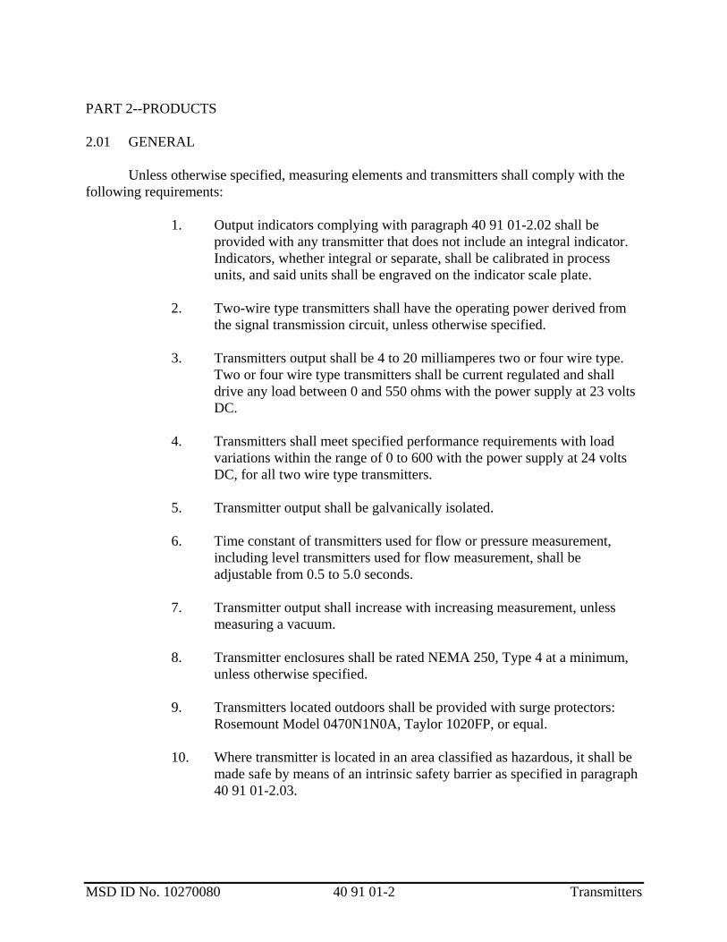
MSD ID No. 10270080 40 91 01-2 Transmitters
PART 2--PRODUCTS 2.01 GENERAL
Unless otherwise specified, measuring elements and transmitters shall comply with the following requirements: 1. Output indicators complying with paragraph 40 91 01-2.02 shall be
provided with any transmitter that does not include an integral indicator. Indicators, whether integral or separate, shall be calibrated in process units, and said units shall be engraved on the indicator scale plate.
2. Two-wire type transmitters shall have the operating power derived from
the signal transmission circuit, unless otherwise specified. 3. Transmitters output shall be 4 to 20 milliamperes two or four wire type.
Two or four wire type transmitters shall be current regulated and shall drive any load between 0 and 550 ohms with the power supply at 23 volts DC.
4. Transmitters shall meet specified performance requirements with load
variations within the range of 0 to 600 with the power supply at 24 volts DC, for all two wire type transmitters.
5. Transmitter output shall be galvanically isolated. 6. Time constant of transmitters used for flow or pressure measurement,
including level transmitters used for flow measurement, shall be adjustable from 0.5 to 5.0 seconds.
7. Transmitter output shall increase with increasing measurement, unless
measuring a vacuum. 8. Transmitter enclosures shall be rated NEMA 250, Type 4 at a minimum,
unless otherwise specified. 9. Transmitters located outdoors shall be provided with surge protectors:
Rosemount Model 0470N1N0A, Taylor 1020FP, or equal. 10. Where transmitter is located in an area classified as hazardous, it shall be
made safe by means of an intrinsic safety barrier as specified in paragraph 40 91 01-2.03.

MSD ID No. 10270080 40 91 01-3 Transmitters
2.02 OUTPUT INDICATOR
Output indicator shall be 90 degree movement milliammeter , 2-1/2-inch enclosed in a NEMA 7/9 meter case. A diode shall be provided to maintain loop continuity in case of meter movement failure or removal. Accuracy shall be within 2 percent of span. Indicator scale shall be graduated in process units and said units shall be engraved on the indicator scale plate.
2.03 INTRINSIC SAFETY BARRIERS
Intrinsic safety barriers for two-wire transmitters shall be of the active, isolating, loop powered type. Barrier shall be Measurement Technology LTD. type MT3042, Stahl 9001/51-280/110/14, Pepperl-Fuchs KFD0-CS-Ex2.51P, or equal. Fieldbus IS barriers shall be Stahl or Pepperl-Fuchs and shall match OWNER’s existing equipment. 2.04 INSTRUMENTATION SPECIFICATION SHEETS (INSTRUSPEC)
General requirements for instruments specified in this section are listed on INSTRUSPEC sheets in paragraph 40 91 01-3.03. Application requirements are specified in the instrument index, paragraph 25 06 30-3.03, and/or on the Drawings. 2.05 PRODUCT DATA The following information shall be provided in accordance with Section 01 33 00: 1. Data specified in paragraph 25 05 00-2.03. PART 3--EXECUTION 3.01 INSTALLATION Installation requirements are specified in Section 25 06 30. 3.02 TESTING Testing requirements are specified in Section 25 08 00.
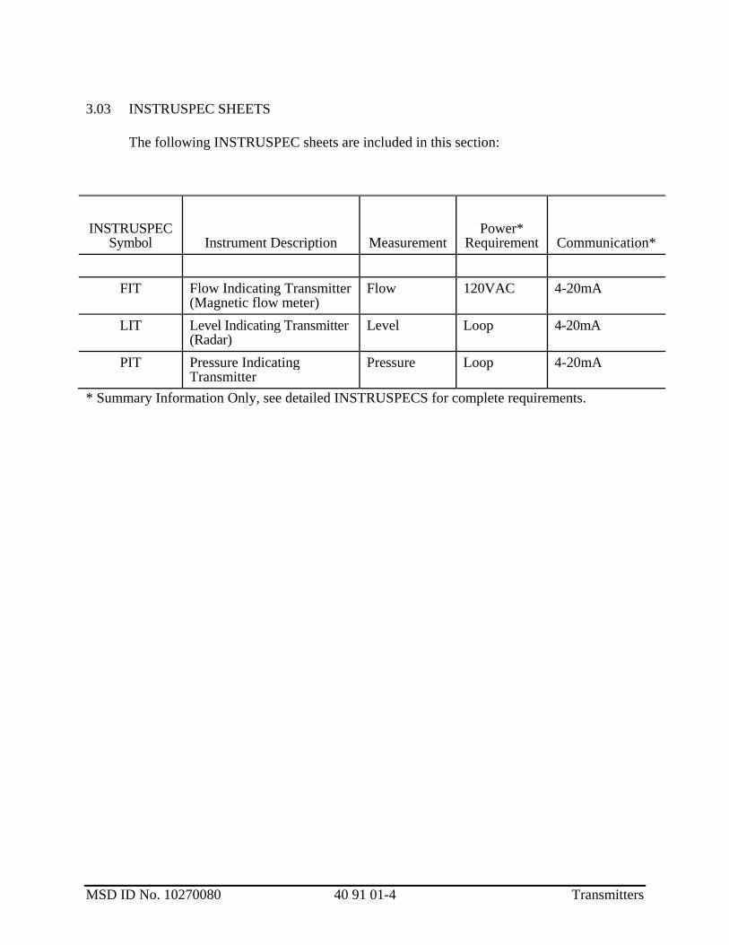
MSD ID No. 10270080 40 91 01-4 Transmitters
3.03 INSTRUSPEC SHEETS The following INSTRUSPEC sheets are included in this section:
INSTRUSPEC
Symbol Instrument Description Measurement Power*
Requirement Communication*
FIT Flow Indicating Transmitter (Magnetic flow meter)
Flow 120VAC 4-20mA
LIT Level Indicating Transmitter (Radar)
Level Loop 4-20mA
PIT Pressure Indicating Transmitter
Pressure Loop 4-20mA
* Summary Information Only, see detailed INSTRUSPECS for complete requirements.
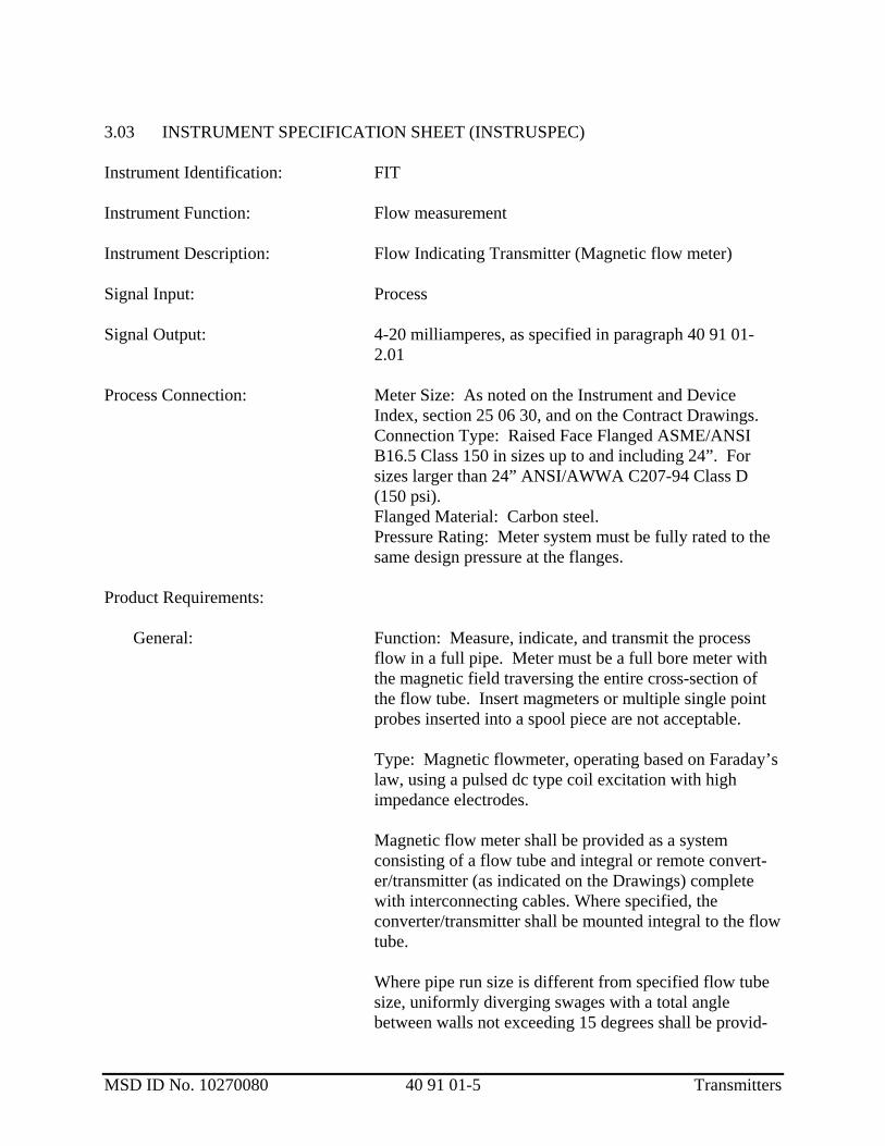
MSD ID No. 10270080 40 91 01-5 Transmitters
3.03 INSTRUMENT SPECIFICATION SHEET (INSTRUSPEC) Instrument Identification: FIT Instrument Function: Flow measurement Instrument Description: Flow Indicating Transmitter (Magnetic flow meter) Signal Input: Process Signal Output: 4-20 milliamperes, as specified in paragraph 40 91 01-
2.01 Process Connection: Meter Size: As noted on the Instrument and Device
Index, section 25 06 30, and on the Contract Drawings. Connection Type: Raised Face Flanged ASME/ANSI
B16.5 Class 150 in sizes up to and including 24”. For sizes larger than 24” ANSI/AWWA C207-94 Class D (150 psi).
Flanged Material: Carbon steel. Pressure Rating: Meter system must be fully rated to the
same design pressure at the flanges. Product Requirements: General: Function: Measure, indicate, and transmit the process
flow in a full pipe. Meter must be a full bore meter with the magnetic field traversing the entire cross-section of the flow tube. Insert magmeters or multiple single point probes inserted into a spool piece are not acceptable.
Type: Magnetic flowmeter, operating based on Faraday’s
law, using a pulsed dc type coil excitation with high impedance electrodes.
Magnetic flow meter shall be provided as a system
consisting of a flow tube and integral or remote convert-er/transmitter (as indicated on the Drawings) complete with interconnecting cables. Where specified, the converter/transmitter shall be mounted integral to the flow tube.
Where pipe run size is different from specified flow tube
size, uniformly diverging swages with a total angle between walls not exceeding 15 degrees shall be provid-

MSD ID No. 10270080 40 91 01-6 Transmitters
ed. 3.03 INSTRUMENT SPECIFICATION SHEET (INSTRUSPEC) Instrument Identification: FIT (continued) Excitation power requirements shall not exceed 15 volt-
amperes. Service: The service shall be as indicated on the contract drawings. Performance: Range: 1000 to 1 for 6” and smaller, 1500 to 1 for 8” and
larger. Accuracy: +/-0.2% of rate Repeatability: +/-0.05% or +/-0.0008ft/s, whichever is
greater. Calibration: Shall be per compliance with OIML R49
Type P standards. Flow Range: As noted on Instrument and Device Index,
section 25 06 30. Converter/ transmitter shall be suitable for full-scale flow
rates from 1.0 to 33 feet per second. Flow Tube: Meter Tube Material: Flow tubes shall be carbon steel for
sizes ¾”-8” and 304 stainless steel for 10” and larger. All flow tubes shall be full-body flanged construction. Liner Material: Flow tube liners for sludge service shall
be polypropylene for up to 8” or Elastomer for 10” and larger.
Electrode Type: Conical self cleaning electrodes. Electrode Material: 316 stainless steel or greater as
recommended by the manufacturer. Enclosure Classification: Standard as submersible in
clean water and buriable with overhead protection (IP68, NEMA 6P).
Housing Material: Shall be Plastic or Epoxy Coated Carbon Steel.
Grounding: Grounding rings and grounding electrodes shall be provided per manufacturer’s recommendation. Meters without grounding electrode shall require grounding ring.

MSD ID No. 10270080 40 91 01-7 Transmitters
3.03 INSTRUMENT SPECIFICATION SHEET (INSTRUSPEC) Instrument Identification: FIT (continued) Flow Tube (continued): Submergence: Continuous in clean water to 30ft and
direct burial 3 to 16 ft IP68/NEMA6P. Octagonal Bore Design: Sensors in sizes of 1.5” to 8”
shall be Octagonal Bore design for blunt profile and reduced piping diameters.
Sensors in sizes 10” and larger shall be provided with full bore design to reduce head loss.
Cable: Only one cable shall be required between sensor and remote transmitter. Meters with multiple cable requirements are not acceptable.
Transmitter: Power: 120 VAC. Display: Three line back-lit graphical LCD display with
capacitive keys’ allows for external configuration without removing covers and compromising the integrity of environmental classifications. The display will also be used for simultaneous indication of flow rate and total flow in user-selectable engineering units, and readout of diagnostic error messages.
Bi-direction flow: Forward and reverse flow indication, total and rate 2x10-digit user configurable display.
Totalizers: Three 9-digit totalizers for forward, reverse and net.
Enclosure: Transmitter housing shall be powder coated cast aluminum, and shall be rated NEMA 4X.
“Though The Glass Control” (no key pad; capacitance keys)
HART protocol standard. Integral Transmitters shall be rotatable up to 270 degrees. Transmitter Module, 180 degrees rotatable. IP 67 Calibration shall be per OIML R49 Type P standards Type “P” continuous self checking capabilities (not just
on start-up). Redundant data storage in sensor and transmitter with
continuous replication of calibration factors, meter size, serial numbers, and site-specific settings.
Infrared service port for meter configuration and diagnostic interrogation.

MSD ID No. 10270080 40 91 01-8 Transmitters
3.03 INSTRUMENT SPECIFICATION SHEET (INSTRUSPEC) Instrument Identification: FIT (continued) Transmitter (continued): The transmitter shall contain all electronics associated
with the magnetic flow meter system. The transmitter shall contain self diagnostics and shall be interchangeable with other units of the same. Features shall include current signal output simulation, and empty pipe detection.
Warranty: Equipment and service warranty shall be delivered free of
defects in material and workmanship and that services shall be free of defects in workmanship. The warranty period for equipment shall end twenty-four (24) months after date of shipment. Software warranty shall be delivered free of defects and will, when properly installed, execute in accordance with published specification. The warranty period for software shall end twelve (12) months from date of shipment.
Acceptable Manufacturers: ABB WaterMaster with no exceptions, to match OWNER’s
existing equipment. Execution: Installation: Install in accordance with manufacturer's instructions,
API RP551, and the specified functional requirements, including but not limited to complying with the straight run requirements upstream and downstream of the flow meter.
Spool pieces or swages shall be bolted to each end of the
flow tube and the entire assembly slid into the pipe run as a unit. Flange bolts shall be tightened to tube manufacturer's specified torque.
Cable: The signal cable between the primary element and
transmitter shall be provided by the system manufacturer. A sufficient length of cable shall be provided for installation of a continuous run between the primary element and the transmitter.

MSD ID No. 10270080 40 91 01-9 Transmitters
3.03 INSTRUMENT SPECIFICATION SHEET (INSTRUSPEC) Instrument Identification: FIT (continued) Application: Application and setup shall be in accordance with
manufacturer’s recommendations and as specified in paragraph 25 06 30-3.03.
Test and Calibration: Test Mode: Provide the ability to verify the accuracy of
the unit and the integrity of the current loop without any external equipment.
Meter calibration shall be compliant to OIML R49 Type P, self-calibration requirements.
Meter must be able to generate periodical simulated signals that verify that the output is within predefined limits.
Coil Inductance and resistance along with electrode voltage and impedance must be verifiable through diagnostic functionality.
Warnings and Alarms: Shall be classified to NAMUR NE 107 standards. Meter must have ability to display severity of warning with “maintenance, check-function, failure and out of spec” warning indications.
Alarm priorities shall be classified as: “None; Maintenance; Out-of-spec; Function check; and Error.”
The duration of an alarm, time-summation for the alarms and time elapsed since last alarm message must be recorded and accessible.
All replacement transmitters shall be interchangeable without need for programming sensor calibration factors, meter size, site information, and serial numbers.
Insitu Calibration Verification: This system shall be used to verify in a quantifiable manner the meter’s current conditions vs. the meters condition when originally manufactured. This calibration verification of the meter shall be performed without need for physical access to the meter flow tube.

MSD ID No. 10270080 40 91 01-10 Transmitters
3.03 INSTRUMENT SPECIFICATION SHEET (INSTRUSPEC) Instrument Identification: FIT (continued) Test & Calibration (cont’d): Measurement diagnostics shall be in accordance with
OILM standards, which shall include self-verification off the flow meter system including, transmitter, cable, electrodes and coils; through software the system shall have the ability to print a certificate of compliance to OIML accuracy standards. Verification software shall be provided with the flowmeters, and shall provide the ability to maintain, print and compare previous calibration information in a trend, bar graph, and text report format.
Meters shall be designated, manufactured, and calibrated in an ISO9001, UKAS/NAMAS, NIST, or NATA certified facility. Facility must have the capability to hold the flow rate at the specified calibration points for a minimum of five minutes to allow stabilization for flow and repeatability point checks.
Additional calibration and testing requirements shall be in accordance with specification Section 25 08 00.

MSD ID No. 10270080 40 91 01-11 Transmitters
3.03 INSTRUMENT SPECIFICATION SHEET--INSTRUSPEC Instrument Identification: LIT Instrument Function: Level Measurement Instrument Description: Level Indicating Transmitter (Radar) Power Supply: As specified in paragraph 40 91 01-2.01 Signal Input Process Signal Output: 4-20 milliamperes, as specified in paragraph 40 91 01-
2.01 Product Requirements
Signal Converter/Transmitter: Signal type: Pulsed radar, 24 to 26 GHz range, maximum output power of 1.0 mWatt. Enclosure: NEMA 4X remote mount and shall be certified for installation in a Class I, Division 2 hazardous location. Display: 4-digitLCD scaled in engineering units. Measuring range: 0-100 ft. Accuracy: ±0.5 in. Analog Output: One isolated 4-20 mA, minimum of 300Ω. Ambient Temperature Range: -20 to +140°F. Process Temperature Range: -40 to +300°F Pressure Range: full vacuum to 120 psig. Sensor: 6 inch horn Process Connection: 6 inch, 150 lb. ANSI flange. Wetted Materials: 316 SS, PTFE, Viton, or as specified in Section 25 06 30 Instrument and Device Index.

MSD ID No. 10270080 40 91 01-12 Transmitters
3.03 INSTRUMENT SPECIFICATION SHEET (INSTRUSPEC) Instrument Identification LIT (continued)
Accessories: Provide necessary mounting hardware and cable glands. Provide handheld infrared programming device, or programming software and cable length.
Acceptable Manufacturers: Ohmart Vega Vegapuls 66, without exception to match
OWNER’s exist equipment
Installation: Install in accordance with manufacturer's instructions and
the Engineer’s installation detail.
Contractor to verify size and type of specified tank connection with approved tank submittals.

MSD ID No. 10270080 40 91 01-13 Transmitters
3.03 INSTRUMENT SPECIFICATION SHEET (INSTRUSPEC) Instrument Identification: PIT Instrument Function: Pressure measurement Instrument Description: Pressure Indicating Transmitter Power Supply: As specified in paragraph 40 91 01-2.01 Signal Input: Process Signal Output: 4-20 milliamperes, as specified in paragraph 40 91 01-
2.01 Process Connection: 1/2-inch male NPT, 316Ti stainless steel. 1-1/2 inch male NPT, 316 stainless steel for direct
mounting to process piping 1-1/2 inch diameter and larger.
Pressure transmitters mounted to annular rings shall be
configured as shown on the instrument detail in the contract drawings. The entire assembly shall be provided by the annular ring supplier, including the annular ring, the pressure transmitter, and the pressure switch. All devices shall be pre-mounted, filled with silicone oil, and pre-calibrated by the supplier at the factory.
Product Requirements: Pressure transmitter shall be capacitance type with a
ceramic pressure sensing diaphragm. Span shall be adjustable over a 20:1 or greater range. Overrange capacity without affecting calibration shall be not less than listed below. Volumetric displacement shall not exceed 0.01 cubic inches over the specified span. Adjustable dampening and external zero adjustment shall be provided. Accuracy shall be 0.1 percent of span.
Transmitter housing shall be rated NEMA 4X and shall be
listed for installation in a Class I, Division 2 hazardous location. Transmitter shall be provided with an integral 4 digit LCD display with bargraph.
Transmitter shall be available with the following
adjustable ranges for gage pressure applications:

MSD ID No. 10270080 40 91 01-14 Transmitters
3.03 INSTRUMENT SPECIFICATION SHEET (INSTRUSPEC) Instrument Identification: PIT (continued) Nominal Range Minimum Span Overpressure Rating PSI PSI PSIG 0 to 1.5 0.075 60 0 to 6 0.3 150 0 to 30 1.5 300 0 to 150 7.5 600 0 to 600 30.0 850 Acceptable Manufacturers: Rosemount Model 3051T without exception to match
OWNER’s existing equipment.. Execution: Installation: Install in accordance with manufacturer's instructions and
the recommendations of API RP551 to the specified requirements.
Root valves shall be provided at all process pressure taps,
except where mounted to annular rings, per the Contract drawings. Gage valves shall be provided at the instrument where the instrument is not within sight of the root valve or where two or more instruments are connected to a single tap. Safety instruments shall not be connected to the same process tap as instruments used for control, indication, or recording. Unless otherwise specified, pressure instruments shall be located as close as practical to the process tap but shall be positioned to permit observation and maintenance. Pressure instruments shall not be supported from process piping less than 1/2-inch diameter.
Pressure transmitters directly mounted to process piping
1-1/2 inch diameter and larger shall be directly connected to the process pipe with a 1-1/2 inch female weld-o-let or similar connection.
The display shall face so that is easily readable.
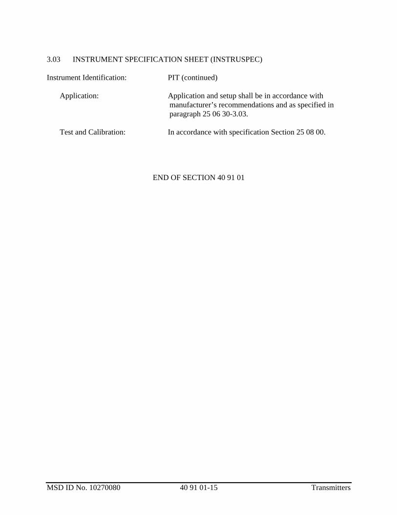
MSD ID No. 10270080 40 91 01-15 Transmitters
3.03 INSTRUMENT SPECIFICATION SHEET (INSTRUSPEC) Instrument Identification: PIT (continued) Application: Application and setup shall be in accordance with
manufacturer’s recommendations and as specified in paragraph 25 06 30-3.03.
Test and Calibration: In accordance with specification Section 25 08 00.
END OF SECTION 40 91 01

MSD ID No. 10270080 44 02 02-1 Submersible Sump Pumps
SECTION 44 02 02 SUBMERSIBLE SUMP PUMPS PART 1--GENERAL 1.01 DESCRIPTION A. SCOPE: This section specifies submersible sump pumps complete with motor, discharge piping, cable, and lifting chain. B. TYPE: Pumps shall be of the submersible, centrifugal non-clog type for use in pumping floor drainage. The pumped liquid could contain up to 20,000 mg/l of solids, industrial solvents and grease. C. OPERATING REQUIREMENTS: Equipment provided under this section shall conform to the following:
Location number
Rated capacity, gpm at BEPa
Low Design Head, Feet
High Design head, feet
Max. speed, rpm
Voltage and
phase
Max. HP
Discharge pipe size,
inches
Max. sphere
passage, size,
inches
S.C.C Sump Pump No. 1
52 18 24 3450 115/1 0.5 1.5 0.75
S.C.C. Sump Pump No. 2
52 18 24 3450 115/1 0.5 1.5 0.75
Tunnel Sump Pump No. 1
49 22 28 3450 115/1 0.5 1.5 0.75
Tunnel Sump Pump No. 2
49 22 28 3450 115/1 0.5 1.5 0.75
Generator Room Sump
49 22 28 3450 115/1 0.5 1.5 0.75
aBecause the pumps are to operate at constant speed, the pump shall be selected so that the rated condition lies within 20 percent (based upon capacity) of the best efficiency point (BEP) on the pump's head-capacity curve. Pumps shall operate and not cavitate within a head range between 10 feet and 40 feet.
MSD ID No. 10270080 44 02 02-2 Submersible Sump Pumps
1.02 REFERENCES This section contains references to the following documents. They are a part of this section as specified and modified. Where a referenced document contains references to other standards, those documents are included as references under this section as if referenced directly. In the event of conflict between the requirements of this section and those of the listed documents, the requirements of this section shall prevail. Unless otherwise specified, references to documents shall mean the documents in effect at the time of Advertisement for Bids or Invitation to Bid (or on the effective date of the Agreement if there were no Bids). If referenced documents have been discontinued by the issuing organization, references to those documents shall mean the replacement documents issued or otherwise identified by that organization or, if there are no replacement documents, the last version of the document before it was discontinued. Where document dates are given in the following listing, references to those documents shall mean the specific document version associated with that date, regardless of whether the document has been superseded by a version with a later date, discontinued or replaced.
Reference Title
ASTM A48 Gray Iron Castings
ASTM A276 Stainless and Heat-Resisting Steel Bars and Shapes
UL 674 Motors and Generators, Electric, for Use in Hazardous Locations, Class I, Groups C and D, Class II, Groups E, F, and G
1.03 ENVIRONMENTAL CONDITIONS The pumps and motors shall be suitable for the service specified. Pumps and motors will be submerged for extended periods of time. The pumped fluid temperature is expected to range from 40 degrees F to 80 degrees F. 1.04 SUBMITTALS The CONTRACTOR shall provide the following submittals in accordance with Section 01 33 00:
1. A copy of this specification section, with addendum updates included, and all referenced and applicable sections, with addendum updates included, with each paragraph check-marked to indicate specification compliance or marked to indicate requested deviations from specification requirements. Check marks () shall denote full compliance with a paragraph as a whole. If deviations from the specifications are indicated, and therefore requested by the CONTRACTOR, each deviation shall be underlined and denoted by a number in the margin to the right of the identified paragraph, referenced to a detailed written explanation of the reasons for requesting the deviation. The ENGINEER shall be the final authority for determining acceptability of

MSD ID No. 10270080 44 02 02-3 Submersible Sump Pumps
requested deviations. The remaining portions of the paragraph not underlined will signify compliance on the part of the CONTRACTOR with the specifications. Failure to include a copy of the marked-up specification sections, along with justification(s) for any requested deviations to the specification requirements, with the submittal shall be sufficient cause for rejection of the entire submittal with no further consideration.
2. A copy of the contract document control diagrams , wiring diagrams, process
control strategies, and process and instrumentation diagrams relating to the submitted equipment, with addendum updates that apply to the equipment in this section, marked to show specific changes necessary for the equipment proposed in the submittal. If no changes are required, the drawing or drawings shall be marked "no changes required". Failure to include copies of the relevant drawings with the submittal shall be cause for rejection of the entire submittal with no further review.
3. Detailed panel layout drawings and wiring diagrams including a detailed bill
of materials, wiring diagrams with wire numbers, terminal numbers, and any additional information required to install and maintain the sump pumps.
4. Manufacturer's data including materials of construction and equipment
weight. 5. Predicted performance curves developed for the specific application.
PART 2--PRODUCTS 2.01 ACCEPTABLE PRODUCTS Sump Pumps were designed around Zoeller Model 153 sump pumps. ABS, Hydromatic, Weil, Barnes, or equal pumps modified to provide specified features and to meet specified operating conditions are acceptable manufacturers.
Level Floats shall be Flygt ENM-10 , or approved equal.
2.02 MATERIAL
Component Material
Pump and motor Cast iron, A48
Casing discharge Cast iron, A48
Impeller Cast iron, A48
All exposed nuts and bolts Stainless steel, ASTM A276, Type 304
Shaft Stainless steel, ASTM 276, Type 303
MSD ID No. 10270080 44 02 02-4 Submersible Sump Pumps
Materials specified are considered the minimum acceptable for the purposes of durability,
strength, and resistance to erosion and corrosion. The CONTRACTOR may propose alternative materials for the purpose of providing greater strength or to meet required stress limitations. However, alternative materials must provide at least the same qualities as those specified for the purpose. 2.03 EQUIPMENT A. IMPELLERS: Impellers shall be statically and dynamically balanced. Maximum solids handling capacity shall be as specified in paragraph 44 02 02-1.01 D. B. BEARINGS: Bearings shall be heavy-duty permanently lubricated ball type. Bearings for pumps 3-inch diameter discharge and larger shall be designed for an L-10 life of 18,000 hours heavy-duty service without requiring additional lubrication. C. PUMP AND MOTOR CASING: Casings shall be constructed of corrosion resistant cast iron and shall be designed to allow removal of all rotating parts from the motor end of the pumps. All mating surfaces where watertight sealing is required shall be machined and fitted with nitrile O-rings. Unless otherwise specified, pump volute shall have vertical discharge. D. MECHANICAL SEAL: Unless otherwise specified, pumps shall be provided with carbon and ceramic faced mechanical seals. E. MOTOR: The motor shall be designed to be nonoverloading over the entire pump curve. The motor housing shall be of submersible construction with the windings operating in a sealed environment. Motors shall be either air or dielectric oil filled with built-in automatic reset overload protection. F. CABLE: Pump motor and detector cables shall be suitable for submersible pump applications. Power for the motor shall be carried by a heavy-duty, flexible, water-resistant portable cable, sealed at the motor bell and of sufficient length to connect to the plug outlet. The cable entry shall prevent water from leaking into the motor due to capillary action even if cable is cut or damaged.
MSD ID No. 10270080 44 02 02-5 Submersible Sump Pumps
G. LIFTING CHAIN:
Each pump shall require a lifting chain of 316 stainless steel (minimum of 3/8 inch link), or a (1/4-inch) diameter 316 stainless steel cable long enough to lower or lift the pump from the bottom of the wet well to the top of the wet well lid with the portable hoist. When these chains/cables are not in use, they will be hooked to the top of the wet well with a locking mechanism that will prevent the chain/cable from falling into the wet well where it might be ingested by the pump. The locking mechanism must be made of a 316-stainless steel and be easily accessible from outside of the wet well. NOTE: The chain or cable must support (3) times the static weight of the pump.
S.C.C. Drainage Sump Pump No. 1 (SS-1), S.C.C. Drainage Sump Pump No. 2 (SS-2), and Generator Room Sump Pump shall have a 316 SS chain (minimum of 3/8 inch link), hung from the ceiling to within 7-feet of the operating floor level. The chain shall be hung from an eye bolt in the ceiling as shown on the Structural Drawings using a SS safety hook. The chain shall terminate with a 4 inch diameter loop (minimum 3/8 inch link) so as to allow a lifting device for pump removal. Entire system shall be rated for lifting up to 250 pounds. H. LEVEL FLOAT SWITCHES:
Furnish and install a float switch level detection system. Floats shall by Flygt ENM-10 or approved equal. Float cables shall have sufficient length to be supported before entering the sump pit and to terminate inside the local control panel.
2.04 CONTROLS Control panels for sump pumps shall be designed in accordance with Section 25 13 16 and in agreement with the electrical control diagrams. One panel is required for each pump arrangement. The Generator Room Sump Pump and the SCC Sump Pumps will each have a dedicated panel for each pump, as indicated on the contract drawings. A single Tunnel Sump Pump Control Panel will contain the controls for both Tunnel Sump Pumps, as indicated on the contract drawings. Cables to enter panels from the bottom and connections shall be sealed. Sump pumps shall be controlled by four hermetically sealed float type level switches. The float switches shall be supported in the sump by a heavy neoprene jacketed wire. A weight shall be attached to the support wire above the float to prevent sharp bends in the wire when the floats are submerged.
Details of the control arrangement can be found on the contract wiring diagrams as well as in the Control Strategies in Section 25 05 00. 2.05 SPARE PARTS Each pump 3 inches and larger shall be provided with the following spare parts: 1 set - all gaskets

MSD ID No. 10270080 44 02 02-6 Submersible Sump Pumps
1 set - all bearings 1 set - mechanical seals
Provide three spare floats. Spare parts shall be packed and boxed as specified in paragraph 44 05 13-2.12. 2.06 PRODUCT DATA Applicable operation and maintenance information (Section 01 78 23) shall be provided in accordance with Section 01 33 00. PART 3--EXECUTION 3.01 INSTALLATION Sump pumps and level floats shall be installed in accordance with the manufacturer's recommendations. The level floats shall be marked with permanent labels inside the well. 3.02 TESTING Each pump system shall be tested for control and capacity over a 2-hour period. END OF SECTION 44 02 02


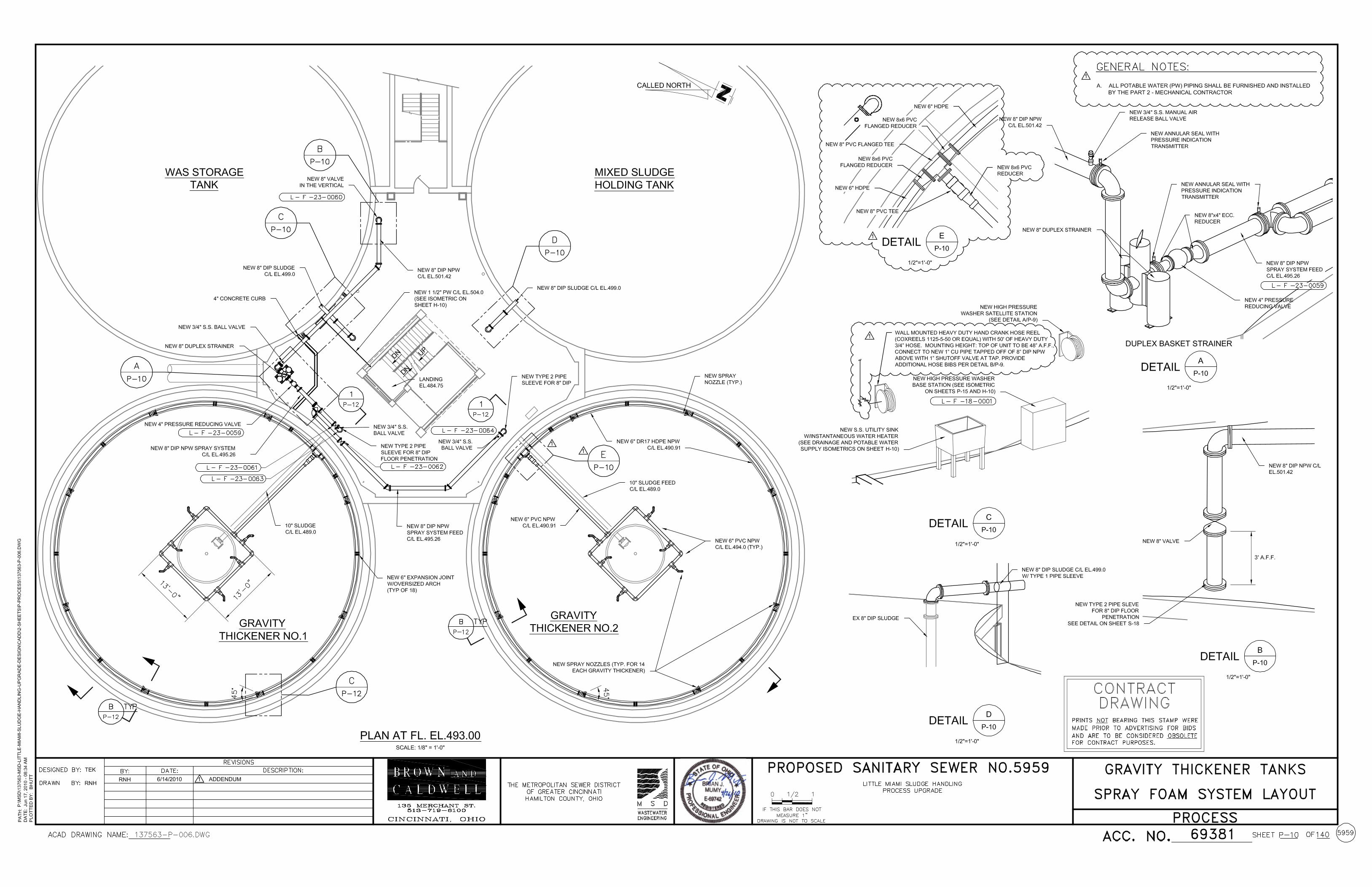
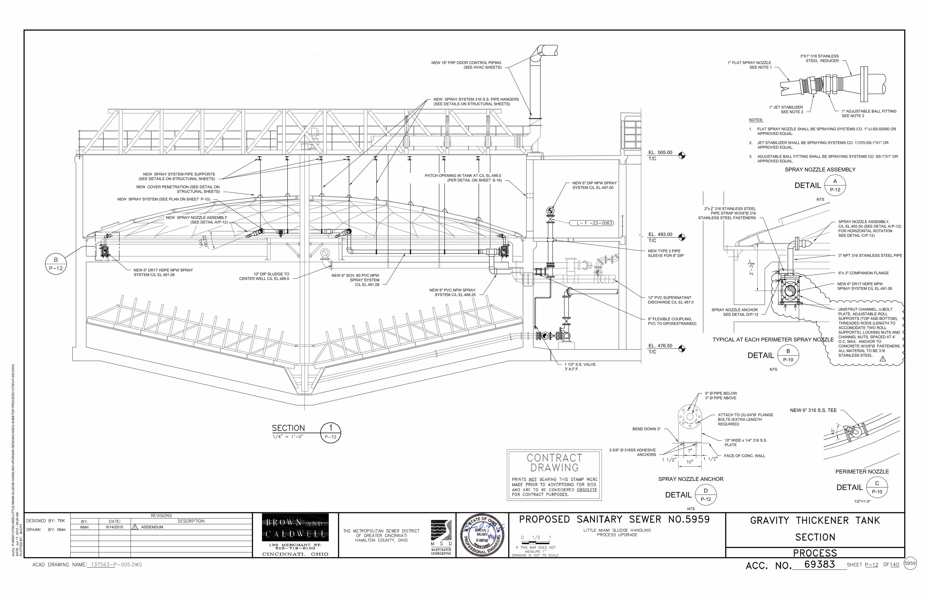


DAVIS BACON AND RELATED ACTS (DBRA)
SUPPLEMENTARY PROVISIONS
Updated July 2009

DAVIS BACON
Davis-Bacon prevailing wage determinations directly follow Section D of these WPCLF Specific Requirements. Any modifications to any of the prevailing wage determinations more than 10 days prior to bid opening shall be issued as an Addendum to this Invitation to Bid Contractor shall conform to all the federal Davis-Bacon and Related Acts (The Act) which requires that all laborers and the mechanics employed by contractors and subcontractors performing on federal contracts (and contractors and subcontractors performing on federally assisted contracts under the related Acts) in excess of $2,000 pay their laborers and mechanics not less than the prevailing wage rates and fringe benefits, as determined by the Secretary of Labor, for corresponding classes of laborers and mechanics employed on similar project in the area. Davis-Bacon rates can be found at: www.gpo.gov/davisbacon/oh Ohio rates can be found at: www.com.ohio.gov/laws (1) Minimum wages.
(i) All laborers and mechanics employed or working upon the site of the work will be paid unconditionally and not less often than once a week, and without subsequent deduction or rebate on any account [except such payroll deductions as are permitted by regulations issued by the Secretary of Labor under the Copeland Act (29 CFR part 3)], the full amount of wages and bona fide fringe benefits (or cash equivalents thereof) due at time of payment computed at rates not less than those contained in the wage determination of the Secretary of Labor which is attached hereto and made a part hereof, regardless of any contractual relationship which may be alleged to exist between the Contractor and such laborers and mechanics.
Contributions made or costs reasonably anticipated for bona fide fringe benefits under section 1 (b )(2) of the Davis-Bacon Act on behalf of laborers or mechanics are considered wages paid to such laborers or mechanics, subject to the provisions of paragraph (a)(1)(iv) of this section; also, regular contributions made or costs incurred for more than a weekly period (but not less often than quarterly) under plans, funds, or programs which cover the particular weekly period, are deemed to be constructively made or incurred during such weekly period. Such laborers and mechanics shall be paid the appropriate wage rate and fringe benefits on the wage determination for the classification of work actually performed, without regard to skill, except as provided in § 5.5(a)(4). Laborers or mechanics performing work in more than one classification may be compensated at the rate specified for each classification for the time actually worked therein provided, that the employer's payroll records accurately set forth the time spent in each classification in which work is performed.
The wage determination [including any additional classification and wage rates conformed under paragraph (a)(l)(ii) of this section] and the Davis Bacon poster (WH-1321) shall be posted at all times by the Contractor and its subcontractors

at the site of the work in a prominent and accessible place where it can be easily seen by the workers.
(ii)
(A) Any class of laborers or mechanics, including helpers, which is not listed in the wage determination and which is to be employed under the contract shall be classified in conformance with the wage determination. The EPA award official shall approve an additional classification and wage rate and fringe benefits therefore only when the following criteria have been met:
(1) The work to be performed by the classification requested is not
performed by a classification in the wage determination; and (2) The classification is utilized in the area by the construction industry;
and (3) The proposed wage rate, including any bona fide fringe benefits,
bears a reasonable relationship to the wage rates contained in the wage determination.
(B) If the Contractor and the laborers and mechanics to be employed in the
classification (if known), or their representatives, and the City agree on the classification and wage rate (including the amount designated for fringe benefits where appropriate), a report of the action taken shall be sent by the sub recipient (s) to the State award official. The State award official will transmit the report, to the Administrator of the Wage and Hour Division, Employment Standards Administration, U.S. Department of Labor, Washington, DC 20210. The Administrator, or an authorized representative, will approve, modify, or disapprove every additional classification action within 30 days of receipt and so advise the State award official or will notify the State award official within the 30-day period that additional time is necessary.
(C) In the event the Contractor, the laborers or mechanics to be employed in
the classification or their representatives, and the City do not agree on the proposed classification and wage rate (including the amount designated for fringe benefits, where appropriate), the award official shall refer the questions, including the views of all interested parties and the recommendation of the State award official, to the Administrator for determination. The Administrator, or an authorized representative, will issue a determination within 30 days of receipt and so advise the contracting officer or will notify the contracting officer within the 30day period that additional time is necessary.
(D) The wage rate (including fringe benefits where appropriate) determined
pursuant to paragraphs (a)(l)(ii)(B) or (C) of this section, shall be paid to all workers performing work in the classification under this contract from the first day on which work is performed in the classification.
(iii) Whenever the minimum wage rate prescribed in the Contract for a class of laborers or mechanics includes a fringe benefit that is not expressed as an hourly rate, the Contractor shall either pay the benefit as stated in the wage determination or shall pay another bona fide fringe benefit or an hourly cash equivalent thereof.
(iv) If the Contractor does not make payments to a trustee or other third person, the
Contractor may consider as part of the wages of any laborer or mechanic the amount of any costs reasonably anticipated in providing bona fide fringe benefits under a plan or program., Provided, that the Secretary of Labor has found, upon the written request of the Contractor, that the applicable standards of the Davis-Bacon Act have been met. The Secretary of Labor may require the Contractor to set aside in a separate account assets for the meeting of obligations under the plan or program.
(2) Withholding. The City shall, upon written request of the EPA Award Official or an
authorized representative of the Department of Labor, withhold or cause to be withheld from the Contractor under this Contract or any other Federal contract with the Contractor, or any other federally-assisted contract subject to Davis-Bacon prevailing wage requirements, which is held by the Contractor, so much of the accrued payments or advances as may be considered necessary to pay laborers and mechanics, including apprentices, trainees, and helpers, employed by the Contractor or any subcontractor the full amount of wages required by the Contract. In the event of failure to pay any laborer or mechanic, including any apprentice, trainee, or helper, employed or working on the site of the work, all or part of the wages required by the Contract, the EPA may, after written notice to the Contractor, sponsor, applicant, or owner, take such action as may be necessary to cause the suspension of any further payment, advance, or guarantee of funds until such violations have ceased.
(3) Payrolls and basic records.
(i) Payrolls and basic records relating thereto shall be maintained by the Contractor during the course of the work and preserved for a period of three years thereafter for all laborers and mechanics working at the site of the work. Such records shall contain the name, address, and social security number of each such worker, his or her correct classification, hourly rates of wages paid (including rates of contributions or costs anticipated for bona fide fringe benefits or cash equivalents thereof of the types described in section 1(b)(2)(B) of the Davis-Bacon Act), daily and weekly number of hours worked, deductions made and actual wages paid. Whenever the Secretary of Labor has found under 29 CFR 5.5(a)(1)(iv) that the wages of any laborer or mechanic include the amount of any costs reasonably anticipated in providing benefits under a plan or program described in section 1(b)(2)(B) of the Davis-Bacon Act, the Contractor shall maintain records which show that the commitment to provide such benefits is enforceable, that the plan or program is financially responsible, and that the plan or program has been communicated in writing to the laborers or mechanics affected, and records which show the costs anticipated or the actual cost incurred in providing such benefits. Contractors employing apprentices or trainees under approved programs shall maintain written evidence of the registration of apprenticeship programs and certification of trainee programs, the

registration of the apprentices and trainees, and the ratios and wage rates prescribed in the applicable programs.
(ii)
(A) The Contractor shall submit weekly, for each week in which any Contract work is performed, a copy of all payrolls to the City. Such documentation shall be available on request of the City or EPA. As to each payroll copy received, the City shall provide written confirmation in a form satisfactory to the State indicating whether or not the project is in compliance with the requirements of29 CFR 5.5(a)(1) based on the most recent payroll copies for the specified week. The payrolls shall set out accurately and completely all of the information required to be maintained under 29 CFR 5.5(a)(3)(i), except that full social security numbers and home addresses shall not be included on the weekly payrolls. Instead the payrolls shall only need to include an individually identifying number for each employee (e.g., the last four digits of the employee's social security number). The required weekly payroll information may be submitted in any form desired. Optional Form WH-347 is available for this purpose from the Wage and Hour Division Web site at http://www.dol.gov/esa/whd/forms/wh347instr.htm or its successor site. The Contractor is responsible for the submission of copies of payrolls by all subcontractors. Contractors and subcontractors shall maintain the full social security number and current address of each covered worker, and shall provide them upon request to the City for transmission to the State or EPA if requested by EPA , the State, the Contractor, or the Wage and Hour Division of the Department of Labor for purposes of an investigation or audit of compliance with prevailing wage requirements. It is not a violation of this section for the Contractor to require a subcontractor to provide addresses and social security numbers to the Contractor for its own records, without weekly submission to the City.
(B) Each payroll submitted shall be accompanied by a “Statement of
Compliance,” signed by the Contractor or subcontractor or his or her agent who pays or supervises the payment of the persons employed under the Contract (including employees of all subcontractors) and shall certify the following:
(1) That the payroll for the payroll period contains the information
required to be provided under § 5.5 (a)(3)(ii) of Regulations, 29 CFR part 5, the appropriate information is being maintained under § 5.5 (a)(3)(i) of Regulations, 29 CFR part 5, and that such information is correct and complete;
(2) That each laborer or mechanic (including each helper,
apprentice, and trainee) employed on the contract during the payroll period has been paid the full weekly wages earned, without rebate, either directly or indirectly, and that no deductions have been made either directly or indirectly from the full wages earned, other than permissible deductions as set forth in Regulations, 29 CFR part 3;

(3) That each laborer or mechanic has been paid not less than the applicable wage rates and fringe benefits or cash equivalents for the classification of work performed, as specified in the applicable wage determination incorporated into the contract.
(C) The weekly submission of a properly executed certification set forth
on the reverse side of Optional Form WH-347 shall satisfy the requirement for submission of the “Statement of Compliance” required by paragraph (a)(3)(ii)(B) of this section.
(D) The falsification of any of the above certifications may subject the
Contractor or subcontractor to civil or criminal prosecution under section 1001 of title 18 and section 231 of title 31 of the United States Code.
(iii) The Contractor or subcontractor shall make the records required under
paragraph (a)(3)(i) of this section available for inspection, copying, or transcription by authorized representatives of the State, EPA or the Department of Labor, and shall permit such representatives to interview employees during working hours on the job. If the Contractor or subcontractor fails to submit the required records or to make them available, the Federal agency or State may, after written notice to the Contractor, sponsor, or City take such action as may be necessary to cause the suspension of any further payment, advance, or guarantee of funds. Furthermore, failure to submit the required records upon request or to make such records available may be grounds for debarment action pursuant to 29 CFR 5.12.
(4) Apprentices and trainees.
(i) Apprentices. Apprentices will be permitted to work at less than the predetermined rate for the work they performed when they are employed pursuant to and individually registered in a bona fide apprenticeship program registered with the U.S. Department of Labor, Employment and Training Administration, Office of Apprenticeship Training, Employer and Labor Services, or with a State Apprenticeship Agency recognized by the Office, or if a person is employed in his or her first 90 days of probationary employment as an apprentice in such an apprenticeship program, who is not individually registered in the program, but who has been certified by the Office of Apprenticeship Training, Employer and Labor Services or a State Apprenticeship Agency (where appropriate) to be eligible for probationary employment as an apprentice. The allowable ratio of apprentices to journeymen on the job site in any craft classification shall not be greater than the ratio permitted to the Contractor as to the entire work force under the registered program. Any worker listed on a payroll at an apprentice wage rate, who is not registered or otherwise employed as stated above, shall be paid not less than the applicable wage rate on the wage determination for the classification of work actually performed. In addition, any apprentice performing work on the job site in excess of the ratio permitted under the registered program shall be paid not less than the applicable wage rate on the wage determination for the work actually performed. If the Contractor is performing construction on a project in a locality other than that in which its program is registered, the ratios and wage rates (expressed in percentages of the

journeyman's hourly rate) specified in the Contractor's or subcontractor's registered program shall be observed. Every apprentice must be paid at not less than the rate specified in the registered program for the apprentice's level of progress, expressed as a percentage of the journeymen hourly rate specified in the applicable wage determination. Apprentices shall be paid fringe benefits in accordance with the provisions of the apprenticeship program. If the apprenticeship program does not specify fringe benefits, apprentices must be paid the full amount of fringe benefits listed on the wage determination for the applicable classification. If the Administrator determines that a different practice prevails for the applicable apprentice classification, fringes shall be paid in accordance with that determination. In the event the Office of Apprenticeship Training, Employer and Labor Services, or a State Apprenticeship Agency recognized by the Office, withdraws approval of an apprenticeship program, the Contractor will no longer be permitted to utilize apprentices at less than the applicable predetermined rate for the work performed until an acceptable program is approved.
(ii) Trainees. Except as provided in 29 CFR 5.16, trainees will not be permitted to
work at less than the predetermined rate for the work performed unless they are employed pursuant to and individually registered in a program which has received prior approval, evidenced by formal certification by the U.S. Department of Labor, Employment and Training Administration. The ratio of trainees to journeymen on the job site shall not be greater than permitted under the plan approved by the Employment and Training Administration. Every trainee must be paid at not less than the rate specified in the approved program for the trainee’s level of progress, expressed as a percentage of the journeyman hourly rate specified in the applicable wage determination. Trainees shall be paid fringe benefits in accordance with the provisions of the trainee program. If the trainee program does not mention fringe benefits, trainees shall be paid the full amount of fringe benefits listed on the wage determination unless the Administrator of the Wage and Hour Division determines that there is an apprenticeship program associated with the corresponding journeyman wage rate on the wage determination which provides for less than full fringe benefits for apprentices. Any employee listed on the payroll at a trainee rate who is not registered and participating in a training plan approved by the Employment and Training Administration shall be paid not less than the applicable wage rate on the wage determination for the classification of work actually performed. In addition, any trainee performing work on the job site in excess of the ratio permitted under the registered program shall be paid not less than the applicable wage rate on the wage determination for the work actually performed. In the event the Employment and Training Administration withdraws approval of a training program, the Contractor will no longer be permitted to utilize trainees at less than the applicable predetermined rate for the work performed until an acceptable program is approved.
(iii) Equal employment opportunity. The utilization of apprentices, trainees and
journeymen under this part shall be in conformity with the equal employment opportunity requirements of Executive Order 11246, as amended, and 29 CFR part 30.
(5) Compliance with Copeland Act requirements. The Contractor shall comply with the

requirements of 29 CPR part 3, which are incorporated by reference in this Contract. (6) Subcontracts. The Contractor or subcontractor shall insert in any subcontracts the
clauses contained in 29 CPR 5.5(a)(l) through (10) and such other clauses as the EPA determines may be appropriate, and also a clause requiring the subcontractors to include these clauses in any lower tier subcontracts. The Contractor shall be responsible for the compliance by any subcontractor or lower tier subcontractor with all the contract clauses in 29 CPR 5.5.
(7) Contract termination: debarment. A breach of the contract clauses in 29 CFR 5.5 may
be grounds for termination of the Contract, and for debarment as a contractor and a subcontractor as provided in 29 CFR 5.12.
(8) Compliance with Davis-Bacon and Related Act requirements. All rulings and
interpretations of the Davis-Bacon and Related Acts contained in 29 CPR parts 1, 3, and 5 are herein incorporated by reference in this Contract.
(9) Disputes concerning labor standards. Disputes arising out of the labor standards
provisions of this Contract shall not be subject to the general disputes clause of this Contract. Such disputes shall be resolved in accordance with the procedures of the Department of Labor set forth in 29 CFR parts 5, 6, and 7. Disputes within the meaning of this clause include disputes between the Contractor (or any of its subcontractors) and the City, State, EPA, the U.S. Department of Labor, or the employees or their representatives.
(10) Certification of eligibility.
(i) By entering into this Contract, the Contractor certifies that neither it (nor he or she) nor any person or firm who has an interest in the Contractor's firm is a person or firm ineligible to be awarded Government contracts by virtue of section 3(a) of the Davis-Bacon Act or 29 CFR 5.12(a)(l).
(ii) No part of this Contract shall be subcontracted to any person or firm ineligible
for award of a Government contract by virtue of section 3(a) of the Davis-Bacon Act or 29 CPR 5.12(a)(l).
(iii) The penalty for making false statements is prescribed in the U.S. Criminal
Code, 18 U.S.C. 1001. (11) Contract Provision for Contracts in Excess of $100,000.
(a) Contract Work Hours and Safety Standards Act. As used in this paragraph (11), the terms laborers and mechanics include watchmen and guards.
(1) Overtime requirements. No contractor or subcontractor contracting for
any part of the Contract work which may require or involve the employment of laborers or mechanics shall require or permit any such laborer or mechanic in any workweek in which he or she is employed on such work to work in excess of forty hours in such workweek unless such laborer or mechanic receives compensation at a rate not less than one and one-halftimes the basic rate of pay for an hours worked in
excess of forty hours in such workweek. (2) Violation; liability for unpaid wages; liquidated damages. In the event of
any violation of the clause set forth in paragraph (a)(l) of this paragraph (11) the Contractor and any subcontractor responsible therefore shall be liable for the unpaid wages. In addition, such Contractor and subcontractor shall be liable to the United States (in the case of work done under contract for the District of Columbia or a territory, to such District or to such territory), for liquidated damages. Such liquidated damages shall be computed with respect to each individual laborer or mechanic, including watchmen and guards, employed in violation of the clause set forth in paragraph (a)(l) of this section, in the sum of $10 for each calendar day on which such individual was required or permitted to work in excess of the standard workweek of forty hours without payment of the overtime wages required by the clause set forth in paragraph (a)(l) of this section.
(3) Withholding for unpaid wages and liquidated damages. The City, upon
written request of the EPA Award Official or an authorized representative of the Department of Labor, shall withhold or cause to be withheld, from any moneys payable on account of work performed by the Contractor or subcontractor under any such contract or any other Federal contract with the Contractor, or any other federally-assisted contract subject to the Contract Work Hours and Safety Standards Act, which is held by the Contractor, such sums as may be determined to be necessary to satisfy any liabilities of the Contractor or subcontractor for unpaid wages and liquidated damages.
(4) Subcontracts. The Contractor or subcontractor shall insert in any
subcontracts the clauses set forth in paragraph (a)(1) through (4) of this section and also a clause requiring the subcontractors to include these clauses in any lower tier subcontracts. The Contractor shall be responsible for compliance by any subcontractor or lower tier subcontractor with the clauses set forth in paragraphs (a)(l) through (4) of this section.
(b) The Contractor or subcontractor shall maintain payrolls and basic payroll records
during the course of the work and shall preserve them for a period of three years from the completion of the Contract for all laborers and mechanics, including guards and watchmen, working on the Contract. Such records shall contain the name and address of each such employee, social security number, correct classifications, hourly rates of wages paid, daily and weekly number of hours worked, deductions made, and actual wages paid. The records to be maintained under this paragraph shall be made available by the Contractor or subcontractor for inspection, copying, or transcription by authorized representatives of the City and the Department of Labor, and the Contractor or subcontractor will permit such representatives to interview employees during working hours on the job.
5. Compliance Verification

(a) The City shall have the right to periodically interview a sufficient number of employees entitled to Davis-Bacon prevailing wages (covered employees) to verify that contractors or subcontractors are paying the appropriate wage rates. As provided in 29 CFR 5.6(a)(6), all interviews must be conducted in confidence. The City shall use Standard Form 1445 or equivalent documentation to memorialize the interviews.
(b) At a minimum, the City shall conduct interviews with a representative
group of covered employees within two weeks of the Contractor or subcontractor's submission of its initial weekly payroll data and two weeks prior to the estimated completion date for the Contract or subcontract. The City shall conduct more frequent interviews if the initial interviews or other information indicates that there is a risk that the Contractor or subcontractor is not complying with Davis-Bacon. The City shall immediately conduct necessary interviews in response to an alleged violation of the prevailing wage requirements. All interviews shall be conducted in confidence.
(c) The City shall periodically conduct spot checks of a representative
sample of weekly payroll data to verify that the Contractor or subcontractors are paying the appropriate wage rates. The City shall follow a spot check schedule based on its assessment of the risks of noncompliance with Davie-Bacon posed by the Contractor or subcontractors and the duration of the Contract or subcontract. At a minimum, the City shall spot check payroll data within two weeks of the Contractor’s or subcontractor's submission of its initial payroll data and two weeks prior to the completion date the Contract or any subcontract. The City shall conduct more frequent spot checks if the initial spot check or other information indicates that there is a risk that the Contractor or subcontractor is not complying with Davis-Bacon. In addition, during the examinations, the City shall verify evidence of fringe benefit plans and payments there under by the Contractors and subcontractors who claim credit for fringe benefit contributions.
(d) The City shall periodically review the Contractor’s and subcontractors’
use of apprentices and trainees to verify registration and certification with respect to apprenticeship and training programs approved by either the D.S Department of Labor or a state, as appropriate, and that the Contractors and subcontractors are not using disproportionate numbers of, laborers, trainees and apprentices. These reviews shall be conducted in accordance with the schedules for spot checks and interviews described in Item 5(b) and (c) above.
(e) The City shall immediately report potential violations of the Davis-
Bacon prevailing wage requirements to the appropriate EPA Davis-Bacon contact and to the appropriate DOL Wage and Hour District Office listed at:
http://www.dol.gov/esaicontacts/whd/arnerica2:htIn .

C. OHIOMEANSJOBS.COM JOB POSTING INSTRUCTIONS The Contractor shall comply with Ohio Means Jobs job posting requirements as outlined below.
Governor Ted Strickland has required that all jobs created and/or retained with American Recovery and Reinvestment Act dollars be posted on OhioMeansJobs.com and with the closest county department of job and family services One-Stop center. The Contractor is responsible for reporting and posting every job created and for reporting positions retained. The U.S. Office of Management and Budget defines jobs or positions created as “those new positions created and filled, or previously existing unfilled positions that are retained as a result of Recovery Act funding.” Positions retained are defined as “those previously existing filled positions that are retained as a result of Recovery Act funding.” A job cannot be reported as both created and retained. It is not necessary to post an unfilled position if a laid-off worker is being recalled to re-fill that position. Here are some basic instructions for posting ARRA-funded jobs. How to Post Job Opportunities on OhioMeansJobs.com Step 1: Go to www.OhioMeansJobs.com Step 2: From the home page, on the left-hand side under “Employers,” select
the third option, labeled “Quick Job Post” Step 3: One the “Quick Job Post” screen, fill out the fields under “General Information” and “Contract Information.” Helpful Hints:
Be sure to read the “Quick Post Terms and Conditions” by the
underlined terms and conditions line in the top blue box. Fields denoted in RED are mandatory. You must enter start and the end dates for how long you would like to
be position to be posted. The system defaults to a 30- day posting. However, you may post positions for as little as 1 or as long as 90 days.
In the “Desired Skills/Duties” field, you may cut and paste from other documents.
To post multiple job openings for the same job description, we suggest that you state the number of openings in the “Job Title” or “Desired Skill/Duties” fields.
Once you post a job, it is not possible for you to edit it. If you need assistance with a job opportunity after you have posted it, you may contact us at the following e-mail address and phone number:
o E-mail: [email protected]

o Phone: 1-888-269-7541. After calling and selecting your desired language, select Option #2, then Option #1, and finally Option #3 to speak with a customer service representative.
Step 4: Once you have completed entering the required information, scroll to the bottom of the page and click on “Save.” Step 5: On the “Job Post Complete” page, you will receive a job post number and will
be given the opportunity to print the page or the job posting. Please record the job post number for later reporting.
Helpful Hints:
Select the “Print this Page” option. This will enable you to keep track of both your posting and your job number. You will need this number if you ever need to contact us and for later reporting.
If you do need to contact us, you may do as the following e-mail address and phone number:
o Email: [email protected] o Phone: 1-888-269-7541. After calling and selecting your
desired language, select Option #2, then Option #1, and finally Option #3 to speak with a customer service representative.
Your job posting will take a few hours to appear on OhioMeansJobs.com
No matter what method you selected under the “Contact Information” section, you can register on OhioMeansJobs.com at any time and use Monster.com tools to search more than 4.5 million resumes, free of charge.
Step 6: From the “Job Post Complete” page on the nearest One-Stop location. Step 7: On the map of Ohio, select the county in which the job opportunity has been
posted. You will be given a name and number for the One-Stop Center serving that county. Please calls to see whether they have additional posting requirements or if the rely solely on the OhioMeansJobs.gov system.
You have now successfully posted your on OhioMeansJobs.com. Thank you for your cooperation and for your participation in Ohio’s recovery. In addition to posting jobs on OhioMeansJobs.com and the nearest One-Stop, Governor Strickland is encouraging all employers to take advantage of the Work Opportunity Tax Credit (WOTC) as well as to reach out to low-income populations regarding new job opportunities. For those employers interested in either the WOTC and/or establishing a plan to target low-income populations, please find additional information below. Work Opportunity Tax Credit (WOTC)

The Work Opportunity Credit Program (http://jfs.ohio.gov/wotc/) is a federal program that provides Ohio employers with a tax credit against their federal tax for hiring individuals from 11 target groups of disadvantage job seekers. Tax credits ranges from $1,200 to $2,400 for all WOTC target groups. Employers may receive a maximum credit of up to $9,000 per eligible employee for the Long Term IV-A target group. Target Groups
1. A member of a family that is receiving or recently received Temporary Assistance to needy Families (TANF)
2. Veteran 3. Formerly Incarcerated 4. A resident of one of the federally designated Empowerment Zone (EZ), Enterprise
Communities (EC) or Renewal Communities (RC), or a Rural Renewal County (RRC) (Crawford, Monroe, Paulding, Seneca, and Van Wert Counties)
5. Vocational Rehabilitation Referral- An applicant who has a physical or mental disability that results in a substantial handicap to employment
6. Food Stamp Recipient 7. Supplemental Security Income (SSI) Recipient 8. Long Term TANF Recipient 9. Summer Youth- Age 16 but not yet 18 years old on hire date
Two New Target Groups Added Under ARRA:
10. Disconnected Youth- ages 16 to 24, regularly attending school, nor regularly employed and lacking sufficient skills to be employable
11. Unemployed Veteran- received unemployment insurance for not less than 4 weeks during the previous year ending on the hire date
We advise employer to include the two WOTC Forms (8850 & 9061) in their hiring packets (application papers). Both of which can be downloaded at the following site: http://jfs.ohio.gov/wotc/index.stm Reaching out to Low-Income Ohioans Firms are encouraged to reach out to the county Job and Family Services in their community, as well as their local One Stop, to connect new jobs with low-income Ohioans. Below you will find links to each of the county Job Families Services as well as Ohio’s One Stops. County Job and Family Services http://www.jfs.ohio.gov/County/cntydir.stm Ohio’s One Stops http://jfs.ohio.gov/workforce/jobseekers/onestopmap.strm

D. ARRA REPORTING The Contractor shall provide to MSDGC all information necessary to comply with ARRA reporting requirements as stated below. The Contractor shall utilize forms and procedures provided by MSDGC to facilitate collection of required information.
Recipients of ARRA financial assistance are required to periodically report on project progress as well as jobs created and/or retained as a result of the ARRA investment. The required information will be reported to the Ohio EPA to both simplify the process and assure that the information which Ohio EPA will in turn report to the USEPA is consistent and complete. While the requirement to report falls to the funding recipient, much of the data to be included in these reports shall be provided by the Contractor. ARRA reports that MSDGC must submit to the Ohio EPA quarterly include:
1. Percent Completion
This is the percent of the scope of the infrastructure investment that was completed during the calendar quarter for the entire project regardless the amount of ARRA assistance the project received.
2. Jobs Created or Retained
This is the number of jobs, expressed as full-time equivalents (FTEs), that were created or retained in the United States, the District of Columbia, Commonwealths, Territories and outlying islands per calendar quarter for the entire project. Jobs created by the primary contractor’s workforce as well as the workforces of subcontractors are to be reported.
3. Employment Impact of Jobs Created or Retained
Provide a narrative description of the employment impact of work done by created/retained jobs. This narrative is to be cumulative per quarter and must be updated for each calendar quarter and at a minimum, address the impact on both the primary contractor’s workforce and the impact on the workforces of subcontractors. At a minimum, the description must include:
(1) A brief description of the types of jobs created/retained in the United States, the District of Columbia, Commonwealths, Territories and outlying islands. This can be reported in terms of broad labor categories, such as “Wastewater Utility Construction.”
(2) A brief description of the types of jobs created and retained in the United States the United States, the District of Columbia, Commonwealths, Territories and outlying islands. (Ex: Full-time construction positions)
E. ARRA PROJECT SIGNAGE REQUIREMENTS The Contractor must provide and display the ARRA Logo on the job site in a manner that informs the public that the project is receiving funding under the American Recovery and Reinvestment Act of 2009. The logo shall be combined with other signage provided at the job site. An electronic version of the logo can be found at www.epa.state.oh.us/defa/ARRA_Logo061009.JPG. Prior to installation of the sign at the project site, the Contractor shall submit a copy of the design of the sign to the City for its review and approval.
P R E – B I D M E E T I N G MINUTES Metropolitan Sewer District of Greater Cincinnati Little Miami Wastewater Treatment Plant Sludge Handling Process Upgrade MSD ID # 10270080, CIP # 2008-54 Time and Place: Thursday, June 10, 2010 / 10:00 AM Lunch Room 225 Wilmer Avenue Cincinnati, OH 45226
1. Sign-In
a. As this was a mandatory meeting, the meeting minutes and attached sign in sheets are a part of Addendum #1.
2. Introductions
a. Owner 1. Jeff Dean, Project Manager, MSDGC 2. Larry Scanlan, Plant Superintendant, MSDGC
b. Engineer 1. Brian Mumy, Project Manager, Brown and Caldwell 2. Tim Koch, Project Principal, Brown and Caldwell
3. Bidding Issues
a. Bid Opening Tuesday, June 22, 2010, 1:30 PM Metropolitan Sewer District of Greater Cincinnati New Administration Building, Room 104 1081 Woodrow Street, Cincinnati, Ohio 45204
b. Questions & Addenda Procedures 1. All bidding questions shall be submitted to Jeff Dean, P.E., MSDGC,
via e-mail: [email protected] 2. Only written/emailed questions will be considered for Addenda. Addenda will be
issued by e-mail and placed on MSD’s website. 3. Question cut off date: June 16, 2010, 5:00 pm.
c. Project Site Visit 1. Additional access to the site will be made available on Tuesday, June 15 from 9:00
AM until 3:00 PM. Contact Mr. Larry Scanlan at (513) 352-4929 before June 15 if interested.
d. This project will utilize Water Pollution Control Loan Fund (WPCLF) funding. As such, it is subject to a Minority-owned Business Enterprise (MBE) utilization goal of 3% and a Women-owned Business Enterprise (WBE) utilization of 3.7%. Bidders are cautioned to read, understand, and complete the WPCLF forms in their entirety. Failure to do so may render the bid non-responsive.
e. Project Duration: 18 months f. Construction Schedule
1. Monthly submittals will be reviewed critically by the Owner. 2. Contractor must submit a recovery schedule in the event the schedule indicates
slippage. The Owner may withhold payment if a recovery schedule is not submitted and implemented within the timeframe specified.
g. Construction Estimate: $4,950,700

Metropolitan Sewer District of Greater Cincinnati Little Miami Wastewater Treatment Plant Sludge Handling Process Upgrade MSD ID # 10270080, CIP # 2008-54 Pre-Bid Meeting Agenda 06/10/10 Page 2
h. Allowances 1. Allowance Items:
a. Network Equipment: $40,000 b. Sludge Pipe Cleaning: $25,000 c. Air Floatation Yard Piping: $20,000 d. Sludge Control Chamber Piping: $75,000
2. All allowances are at the sole discretion of the Owner. The Owner will inform the Contractor in writing when an allowance will be used to cover unanticipated additional work. All allowance costs not used will be deducted from the Contract at project completion.
4. Administrative Issues
a. Permits and Licenses (Section 01 11 00) 1. Contractor to secure and pay for all permits.
b. Required Meetings (before starting work) 1. Pre-Construction, To Be Scheduled
c. Payment Procedure / Retainage / Liquidated Damages 1. Payments based on approved Schedule of Values 2. Payment of 92% of Contractor estimates until project is 50% complete 3. Liquidated damages per State of Ohio, Department of Transportation Construction
Materials and Specifications 5. Project Description
Sludge Handling Building
a. Demolish restroom and relocate air compressor glycol system and air receiver tank for installation of new Electrical Room.
b. Remove existing boilers and install new HVAC systems. c. Replace roofing, windows, and several doors. d. Electrical, Instrumentation and Control: Install new MCCs, conduit and wiring systems for all
processes. Install new lighting. Install new PLC and Network cabinets. Install new iClient (Operator Station).
Sludge Control Chamber/Tunnel
a. Demolish unused process piping and valves and install new piping and valves to simplify
operation. b. Replace Mixed Sludge Pump #1, Primary Sludge Pumps #1 and 2, and the Mixed Sludge
Pump #2 motor. c. Replace Sludge Control Chamber penthouse structure and install new floor access hatch and
monorail hoist for equipment handing. d. Replace all sump pumps. e. Replace all HVAC equipment. f. Install new NPW spray system in Gravity Thickener Tanks for foam control. g. Install new hot water pressure washer system.

Metropolitan Sewer District of Greater Cincinnati Little Miami Wastewater Treatment Plant Sludge Handling Process Upgrade MSD ID # 10270080, CIP # 2008-54 Pre-Bid Meeting Agenda 06/10/10 Page 3
h. Clean existing process piping and replace expansion joints. i. Electrical, Instrumentation and Control: Replace all wiring, conduit, local control stations,
instrumentation, and lighting. Primary Sludge Pump Building
a. Replace air handing unit and exhaust fan. b. Electrical: Install wiring and conduit for new air handling unit and exhaust fan, demolish same
for old air handling unit and exhaust fan.
Dewatering Building
a. Replace Mixed Sludge flow meter. b. Install Ethernet-based processor in PLC L3_41. Yard Piping a. Install new 16” Air Floatation Underflow pipe and valve chambers. Contractor must field
locate pipe under tunnel to avoid existing piles. b. Install new drainage pipe for existing sludge tanks. c. Install natural gas piping for new HVAC equipment. Electrical and I&C Overview
a. Replace the existing split-bus MCC-1 with two separate MCCs. b. Replace the PLC panel serving the Sludge Handling Building and Sludge Control Chamber. c. Replace all wiring and conduit from the existing PLC and MCC to the respective equipment. d. Replace all lighting in the Sludge Handling Building and Sludge Control Chamber. e. Install an iClient workstation and network cabinet in the new electrical room. f. All programming for PLC & SCADA systems will be performed by the Owner. g. Contractor will work closely with the Owner to coordinate the installation of the new systems
and the replacement of the existing PLCs.
6. Work Sequence a. Continuity of Plant Operations
1. The Little Miami WWTP operates 24 hours a day, 7 days a week. Treatment processes, flows, and monitoring capabilities must not be disrupted.
b. Work Constraints 1. Multiple shutdowns for any process may not occur on consecutive days or the same
day without prior approval from the Owner. 2. Primary Sludge Flow may not be shut down for more than 4 hours at a time. 3. The Primary Effluent Channel may not be shut down for more than 1 hour at a time. 4. The 16-inch pipe to Primary Influent may not be shut down for more than 32 hours at
a time. 5. The 16-inch pipe to Primary Effluent may not be shut down for more than 32 hours
at a time, until valve upstream of cross connection is installed.

Metropolitan Sewer District of Greater Cincinnati Little Miami Wastewater Treatment Plant Sludge Handling Process Upgrade MSD ID # 10270080, CIP # 2008-54 Pre-Bid Meeting Agenda 06/10/10 Page 4
6. Air Flotation Underflow to either the Primary Effluent (preferred flow path) or Primary Influent may not be shut down for more than 8 hours at a time.
7. Thickened Waste Activated Sludge to the Mixed Sludge Tank may not be shut down for more than 8 hours at a time.
8. Waste Activated Sludge Flow may not be shut down for more than 8 hours at a time. 9. Both Gravity Thickener Tanks and associated pumps may not be shut down for more
than 32 hours at a time. One Gravity Thickener Tank and pump must be in service at all other times.
10. The Mixed Sludge system may not be shut down for more than 32 hours at a time. 11. One of the two Thickened Sludge Pumps must be operable at all times with exception
to the Gravity Thickener Tank outage. 12. The Compressed Air system may not be shut down for more than 1 hour. 13. The Compressor Glycol System may not be shut down for more than one hour. The
Contractor may provide a potable water connection to the Air Compressors for cooling while the Compressor Glycol System is out of service for up to a maximum of 14 days.
14. Natural gas service to the Air Floatation Building may not be shut down for more than 6 hours at a time between November 1 and March 31.
15. All demolition Work and masonry construction must be completed in the Electrical Room prior to MCC or panel installations.
16. The existing MCC-1 and lighting panel LP-8 must remain in service until the new MCCs and lighting panel have been fully commissioned and all loads have been transferred to the new electrical systems.
17. The existing PLC-12 and network cabinet must remain in service until the new PLC L3_14 and network cabinet have been fully commissioned and all I/O associated with PLC-12 have been transferred to the new PLC. Conduit connected to the PLC-12 cabinet and network cabinet must remain undisturbed during demolition and construction.
18. Plant traffic must be maintained at all times per Section 01 14 00. c. Suggested Work Sequence
Yard Piping a. The 16-inch yard piping to Primary Influent may require a temporary cap or plug to maintain
Primary Tank Drain Pump capability. The Primary Tank Drain Pumps discharge into the 16-inch to Primary Influent at the Primary Settling Tanks.
b. The 16-inch to Primary Effluent may require temporary bulkheads installed in the effluent channel to allow a plug to be installed to keep the Primary Settling Tanks in service during work on the 16-inch to Primary Effluent.
c. Air Floatation Underflow may be routed to either the Primary Effluent (preferred flow path) or Primary Influent.

Metropolitan Sewer District of Greater Cincinnati Little Miami Wastewater Treatment Plant Sludge Handling Process Upgrade MSD ID # 10270080, CIP # 2008-54 Pre-Bid Meeting Agenda 06/10/10 Page 5
Sludge Handling Building a. The Glycol System and Air Receiver must be relocated per drawings and constraints prior to
work in the new electrical room. b. The compressed air system may be temporarily in operation without the air receiver online.
The CONTRACTOR must closely monitor operation while the receiver is out of service. Temporary piping may be required to maintain compressed air service.
c. The existing PLC-12 cabinet and network cabinet must be kept in service and protected from construction debris. Provide temporary mounting for network cabinet to allow the restroom wall to be removed – the cabinet must remain stationary at all times due to fiber optic cables.
d. The Electrical Room must be enclosed, cleaned, and HVAC system functional and operating prior to installation of MCC’s and PLC start-up.
e. Demo existing MCC-1 after all equipment has been switched over to the new MCCs and MCC-1 has been decommissioned.
f. Pump the Settled Sewage wet well dry prior to demolition of the Settled Sewage pumps and piping. The Settled Sewage Pumps are not operable. Temporary pumps and piping may be required to dewater the wet well.
g. Plug or pancake NPW piping entering the basement of the SHB to maintain NPW service to the AF Building.
Sludge Control Chamber
a. Temporary piping will be required to meet the construction constraints for both the mixed
sludge pumping and thickened sludge pumping. b. Install power and signal wiring and conduit to one pump prior to taking the duplicate unit off
line, coordinating with piping and mechanical Work. Signal wiring must be tested and terminated to any field instruments required for pump to run in Local Mode and in Remote PC Auto Mode based on the Control Strategy, including but not limited to tank level, pump flow switches, pressure switches, transmitters, hand switches, solenoid valves, and interface with the Sludge Disposal Building PLC for required interlocks and controls.
7. Construction Issues a. Submittals (Section 01 33 00)
1. The Owner utilizes a Document Control and Management system. b. Coordination
1. Two weeks advance notice is required with written approval by the Owner to take any utility, system, or process out of service.
c. Hours of Construction 1. 7:00 am to 5:00 pm, Monday through Friday
d. Security e. Staging Area (Sheet G – 6) f. Asbestos
1. Asbestos wall panels are currently installed in the second floor of the Sludge Control Chamber. These panels will be removed by the Owner prior to construction.

Metropolitan Sewer District of Greater Cincinnati Little Miami Wastewater Treatment Plant Sludge Handling Process Upgrade MSD ID # 10270080, CIP # 2008-54 Pre-Bid Meeting Agenda 06/10/10 Page 6
8. Questions / Answers Question: What is the definition of “an out of town Bidder” as described on page 10 of the
Bid Booklet (Instructions to Bidders)? Answer: Clarification will be sought. Question: Must Bidders submit the entire Bid Booklet? Answer: No. Only required forms must be submitted. See the Legal Notice. Question: Is this project funded by ARRA funds? Answer: No. This will be clarified by Addendum. Question: Is June 15 the only day additional site visits will be allowed? Answer: Yes. Question: Will the Bid Opening be extended? Answer: No. Question: The Drawings do not indicate an quantity of concrete to be repaired. Can an area
be defined? Answer: This will be clarified by Addendum. Question: Should the Gravity Thickener Tanks be considered confined spaces? Answer: Yes. Question: Questions were asked about responsibility for demolition work. The bidder will
clarify his question by email. Answer: Will clarify when question is submitted. Question: What is the anticipated Notice to Proceed Date? Answer: This date is not currently known. 9. Project Tour
**END OF MEETING MINUTES**