the lund-york-cologne calorimeter (lycca): …lup.lub.lu.se/search/ws/files/3719630/4001016.pdf ·...
TRANSCRIPT

LUND UNIVERSITY
PO Box 117221 00 Lund+46 46-222 00 00
The Lund-York-Cologne Calorimeter (LYCCA): Concept, Design and PrototypeDevelopments for a FAIR-NUSTAR Detector System to Discriminate Relativistic Heavy-ion Reaction Products
Golubev, Pavel; Wendt, A.; Scruton, L.; Taprogge, J.; Rudolph, Dirk; Reiter, P.; Bentley, M.A.; Avdeichikov, Vladimir; Boutachkov, P.; Fox, S. P.; Gerl, J.; Goergen, Ch.; Hoischen,Robert; Kurz, N.; Singh, B. S. Nara; Pascovici, G.; Pietri, S.; Schaffner, H.; Taylor, M. J.;Thiel, S.; Wollersheim, H. J.Published in:Nuclear Instruments & Methods in Physics Research. Section A: Accelerators, Spectrometers, Detectors, andAssociated Equipment
DOI:10.1016/j.nima.2013.04.058
Published: 2013-01-01
Link to publication
Citation for published version (APA):Golubev, P., Wendt, A., Scruton, L., Taprogge, J., Rudolph, D., Reiter, P., ... Wollersheim, H. J. (2013). TheLund-York-Cologne Calorimeter (LYCCA): Concept, Design and Prototype Developments for a FAIR-NUSTARDetector System to Discriminate Relativistic Heavy-ion Reaction Products. Nuclear Instruments & Methods inPhysics Research. Section A: Accelerators, Spectrometers, Detectors, and Associated Equipment, 723, 55-66.DOI: 10.1016/j.nima.2013.04.058
General rightsCopyright and moral rights for the publications made accessible in the public portal are retained by the authorsand/or other copyright owners and it is a condition of accessing publications that users recognise and abide by thelegal requirements associated with these rights.
• Users may download and print one copy of any publication from the public portal for the purpose of privatestudy or research. • You may not further distribute the material or use it for any profit-making activity or commercial gain • You may freely distribute the URL identifying the publication in the public portal

Take down policyIf you believe that this document breaches copyright please contact us providing details, and we will removeaccess to the work immediately and investigate your claim.
Download date: 12. Aug. 2018

Department of Physics
LUP Lund University Publications
Institutional Repository of Lund University Found at: http://www.lu.se
This is an author produced version of a paper published in NuclearInstrumentsandMethodsinPhysicsResearchA
This paper has been peer-reviewed but does not include the final
publisher proof-corrections or journal pagination.
Citation for the published paper: Author: P.Golubevetal.
Title: TheLund–York–CologneCalorimeter(LYCCA):Concept,designandprototypedevelopmentsforaFAIR‐NUSTARdetectorsystemto
discriminaterelativisticheavy‐ionreactionproducts Journal: Nucl.Instr.Meth.A723,55(2013)
DOI: 10.1016/j.nima.2013.04.058
Access to the published version may require subscription.

The Lund-York-Cologne Calorimeter (LYCCA):Concept, design and prototype developments for a FAIR-NUSTAR detector
system to discriminate relativistic heavy-ion reaction products
P. Golubeva, A. Wendtb, L. Scrutonc, J. Taprogge1,2,b, D. Rudolpha, P. Reiterb, M.A. Bentleyc, V. Avdeichikova,P. Boutachkovd,e, S.P. Foxc, J. Gerld, Ch. Gorgenb, R. Hoischen3,a,d, N. Kurzd, B.S Nara Singhc, G. Pascovicib,
S. Pietrid, H. Schaffnerd, M.J. Taylor4,c, S. Thielb, H.J. Wollersheimd
aDepartment of Physics, Lund University, SE-22100 Lund, SwedenbInstitut fur Kernphysik, Universitat zu Koln, D-50937 Koln, Germany
cDepartment of Physics, University of York, York YO10 5DD, United KingdomdGSI Helmholtzzentrum fur Schwerionenforschung GmbH, D-64291 Darmstadt, GermanyeInstitut fur Kernphysik, Technische Universitat Darmstadt, D-64289 Darmstadt, Germany
Abstract
The concept, design and prototype developments for the Lund-York-Cologne CAlorimeter (LYCCA) is presented.LYCCA is a modular device for the NUclear STructure, Astrophysics and Reactions (NUSTAR) science pillar of theFacility for Antiproton and Ion Research (FAIR) at Darmstadt, Germany. LYCCA is designed to discriminate heavyions produced in nuclear reactions induced by relativisticradioactive ion beams. Measurements of energy loss, totalenergy, and time-of-flight allows the derivation of proton number,Z, and mass number,A, of the reaction products.LYCCA-inherent tracking of the flight paths of the reaction products enables coincident HIgh-resolution in-beamγ-ray SPECtroscopy (HISPEC) of atomic nuclei far from the line ofβ-stability.
Keywords: relativistic heavy ions, nuclear structure, time of flight,energy loss, total energy,A andZ identification
1. Introduction and Requirements1
The NUclear STructure, Astrophysics and Reactions2
(NUSTAR) science pillar [1] of the Facility for Antipro-3
ton and Ion Research (FAIR) at Darmstadt, Germany4
awaits beams of relativistic radioactive ions with un-5
precedented intensities. The major incentive is to study6
the atomic nucleus at its extremes of proton-to-neutron7
ratio, which is of immediate relevance towards and mo-8
tivated by heavy-element production in the course of9
stellar evolution.10
The HIgh-resolution in-beam SPECtroscopy (HIS-11
PEC) [2] experiment within NUSTAR addresses nuclear12
structure questions by using radioactive beams to be de-13
livered by the new, super-conducting FRagment Sepa-14
rator (Super-FRS) [3]. The beam energies are typically15
some 100-300 MeV/u. Single-step Coulomb excitation16
and nuclear fragmentation reactions at these intermedi-17
ate energies as well as inelastic scattering, transfer and18
knock-out reactions are envisaged. The experiments19
Email address:[email protected] (P. Golubev)
will provide information relevant for the shell structure20
of atomic nuclei far from the line ofβ-stability, and21
more specifically low-lying excitation energies, transi-22
tion probabilities, or single-particle spectroscopic fac-23
tors, to name but a few.24
The core of HISPEC is the use of high-resolution Ge25
detectors at one of the focal planes of the Super-FRS,26
i.e. to perform high-resolution in-beam spectroscopy27
of excited nuclear quantum states via theirγ-ray de-28
cay; therefore, the HISPEC set-up foresees at its core29
the European Advanded GAmma-ray Tracking Array30
(AGATA) [4], surrounding the secondary target posi-31
tion. To enable event-by-event correlations of theγ rays32
with the nuclear residues, HISPEC will comprise a new33
generation of beam tracking and identification detec-34
tors placed in front of and behind the secondary target.35
Here, the Lund-York-Cologne CAlorimeter (LYCCA)36
has the central role of determining both proton number,37
Z, and mass number,A, of the final reaction products;38
by itself or in conjunction with a magnetic spectrom-39
eter. Until HISPEC becomes operational, a subset of40
LYCCA detectors is being commissioned and used for41
Preprint submitted to Nuclear Instruments and Methods A April 25, 2013
the PRESPEC-AGATA [5] physics campaign at the ex-42
isting FRS facility [6] at the GSI Helmholtzcentre for43
Heavy Ion Research in Darmstadt, Germany.44
∆ EE−(x,y)(x,y)
(Sup
er−)
FRS det
ecto
rs
LYCCA T
oF S
tart
LYCCA T
oF T
arge
t
LYCCA T
arge
t DSSSD
targ
et
seco
ndar
y rea
ction
LYCCA W
all D
SSSD
LYCCA W
all C
sI
radio
activ
e ion
bea
m
incom
ing re
lativi
stic
LYCCA T
oF S
top
d d
dininToF ,
tottotToF ,outToF ,out
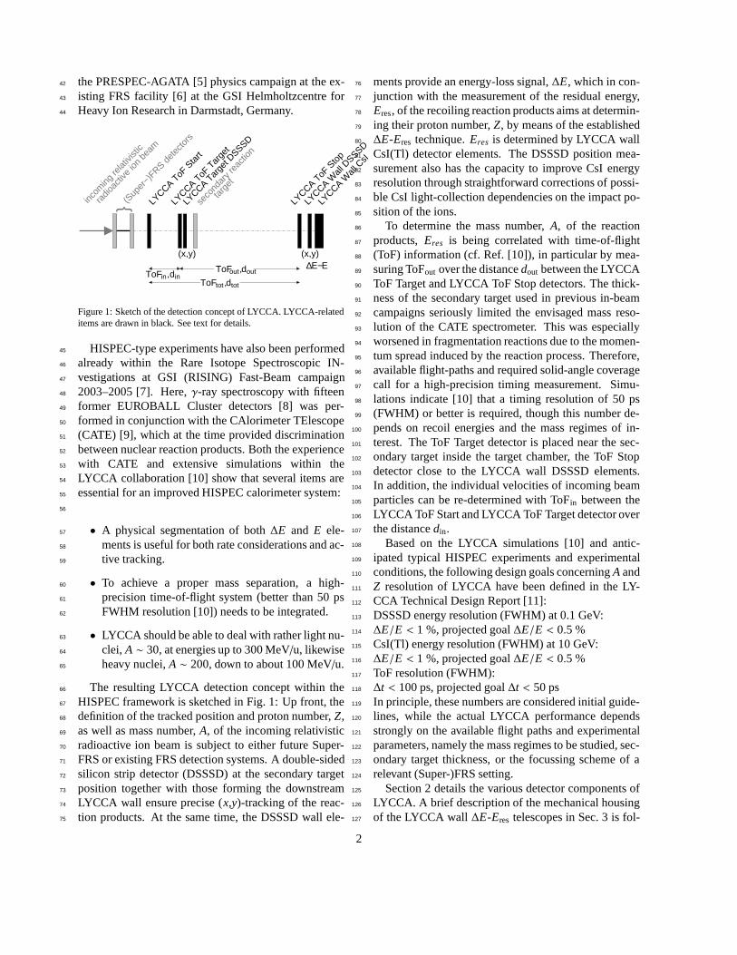
Figure 1: Sketch of the detection concept of LYCCA. LYCCA-relateditems are drawn in black. See text for details.
HISPEC-type experiments have also been performed45
already within the Rare Isotope Spectroscopic IN-46
vestigations at GSI (RISING) Fast-Beam campaign47
2003–2005 [7]. Here,γ-ray spectroscopy with fifteen48
former EUROBALL Cluster detectors [8] was per-49
formed in conjunction with the CAlorimeter TElescope50
(CATE) [9], which at the time provided discrimination51
between nuclear reaction products. Both the experience52
with CATE and extensive simulations within the53
LYCCA collaboration [10] show that several items are54
essential for an improved HISPEC calorimeter system:55
56
• A physical segmentation of both∆E and E ele-57
ments is useful for both rate considerations and ac-58
tive tracking.59
• To achieve a proper mass separation, a high-60
precision time-of-flight system (better than 50 ps61
FWHM resolution [10]) needs to be integrated.62
• LYCCA should be able to deal with rather light nu-63
clei, A ∼ 30, at energies up to 300 MeV/u, likewise64
heavy nuclei,A ∼ 200, down to about 100 MeV/u.65
The resulting LYCCA detection concept within the66
HISPEC framework is sketched in Fig. 1: Up front, the67
definition of the tracked position and proton number,Z,68
as well as mass number,A, of the incoming relativistic69
radioactive ion beam is subject to either future Super-70
FRS or existing FRS detection systems. A double-sided71
silicon strip detector (DSSSD) at the secondary target72
position together with those forming the downstream73
LYCCA wall ensure precise (x,y)-tracking of the reac-74
tion products. At the same time, the DSSSD wall ele-75
ments provide an energy-loss signal,∆E, which in con-76
junction with the measurement of the residual energy,77
Eres, of the recoiling reaction products aims at determin-78
ing their proton number,Z, by means of the established79
∆E-Eres technique.Eres is determined by LYCCA wall80
CsI(Tl) detector elements. The DSSSD position mea-81
surement also has the capacity to improve CsI energy82
resolution through straightforward corrections of possi-83
ble CsI light-collection dependencies on the impact po-84
sition of the ions.85
To determine the mass number,A, of the reaction86
products,Eres is being correlated with time-of-flight87
(ToF) information (cf. Ref. [10]), in particular by mea-88
suring ToFout over the distancedout between the LYCCA89
ToF Target and LYCCA ToF Stop detectors. The thick-90
ness of the secondary target used in previous in-beam91
campaigns seriously limited the envisaged mass reso-92
lution of the CATE spectrometer. This was especially93
worsened in fragmentation reactions due to the momen-94
tum spread induced by the reaction process. Therefore,95
available flight-paths and required solid-angle coverage96
call for a high-precision timing measurement. Simu-97
lations indicate [10] that a timing resolution of 50 ps98
(FWHM) or better is required, though this number de-99
pends on recoil energies and the mass regimes of in-100
terest. The ToF Target detector is placed near the sec-101
ondary target inside the target chamber, the ToF Stop102
detector close to the LYCCA wall DSSSD elements.103
In addition, the individual velocities of incoming beam104
particles can be re-determined with ToFin between the105
LYCCA ToF Start and LYCCA ToF Target detector over106
the distancedin.107
Based on the LYCCA simulations [10] and antic-108
ipated typical HISPEC experiments and experimental109
conditions, the following design goals concerningA and110
Z resolution of LYCCA have been defined in the LY-111
CCA Technical Design Report [11]:112
DSSSD energy resolution (FWHM) at 0.1 GeV:113
∆E/E < 1 %, projected goal∆E/E < 0.5 %114
CsI(Tl) energy resolution (FWHM) at 10 GeV:115
∆E/E < 1 %, projected goal∆E/E < 0.5 %116
ToF resolution (FWHM):117
∆t < 100 ps, projected goal∆t < 50 ps118
In principle, these numbers are considered initial guide-119
lines, while the actual LYCCA performance depends120
strongly on the available flight paths and experimental121
parameters, namely the mass regimes to be studied, sec-122
ondary target thickness, or the focussing scheme of a123
relevant (Super-)FRS setting.124
Section 2 details the various detector components of125
LYCCA. A brief description of the mechanical housing126
of the LYCCA wall∆E-Eres telescopes in Sec. 3 is fol-127
2

lowed by a brief overview of hitherto used processing128
and read-out electronics in Sec. 4. Section 5 illustrates129
very first in-beam commissioning spectra of LYCCA,130
thereby confirming the achievement of the design goals131
indicated above. The paper concludes with an outlook132
towards LYCCA as a FAIR-NUSTAR detection device.133
2. The LYCCA Detector Components134
2.1. The Target DSSSD135
Double sided silicon strip detectors (DSSSD) are136
common in physics experiments as an apparatus to mea-137
sure the energy loss,∆E, and position, (x,y), of particles138
passing through the silicon bulk of the detectors. The139
silicon wafers used as LYCCA target DSSSDs are ion140
implanted, silicondioxide (SiO2) passivated, and oper-141
ated totally depleted with floating guard rings. They are142
obtained from RADCON Limited.143
The nominally 300-320µm thick wafers are square144
shaped, 60.1 mm ×60.1 mm in size with an active145
area of 58.5 mm ×58.5 mm. The active area is sub-146
divided into 32 strips on both front (junction) p-side147
and rear (ohmic) n-side in orthogonal directions pro-148
viding two dimensional position information. With149
58.5 mm/32=1.83 mm, the pitch of the p-side strips is150
1.80 mm with an interstrip SiO2 isolation of 30µm. To151
improve interstrip capacitive and resistive isolation from152
the adjacent n-strips on the ohmic side, a so-called p-153
type zone or p-stop structure surrounding n-strips was154
implanted. Thus the pitch size on the ohmic side is155
1.63 mm with interstrip distances of 200µm.156
Figure 2: Photograph of a target DSSSD detector.
Leakage currents, upon delivery, range between 5-157
10 nA per strip with modest capacities of 33 pF per strip158
at full depletion voltage, which is typically reached at159
50 V. The energy resolution and crosstalk was measured160
by scanning detectors with collimated228Th and241Am161
α-particle sources. A typical spectrum for this type of162
DSSSD, obtained in a test chamber using standard LY-163
CCA vacuum feedthrough, cabling, and electronics (see164
Secs. 3 and 4), is shown in Fig. 5(a).165
The thickness of the dead layers on both sides of de-166
tectors was determined by measuring the energy loss of167
the α particles by irradiating the detector from differ-168
ent incident angles. They are found to be∼ 1.0 µm169
Si-equivalent on the junction side and∼ 2.0 µm on the170
ohmic side. To optimize charge collection on the rear171
side of the detector the full depletion voltage was mea-172
sured by injectingα particles into the ohmic side and173
maximizing detector response as a function of applied174
bias voltage.175
The target DSSSD is mounted on a printed circuit176
board made of FR4 together with connectors and gold177
plated pads for strips bonding. Due to possible harsh178
radiation damage all components and material used for179
detector packaging allow temperature annealing at low-180
to-medium temperature for few days. The detector181
frame is mechanically compatible for mounting into the182
secondary reaction chamber together with the ToF Tar-183
get detectors (cf. Secs. 2.3.2 and 2.3.3) and various sec-184
ondary reaction targets.185
2.2. The LYCCA∆E-Eres Wall Telescope186
The requirements described in Sec. 1 call for the use187
of telescopes based on segmented semiconductor detec-188
tors backed by segmented inorganic scintillators read-189
out by photodiodes (PD). Such a device presents a pow-190
erful tool for charged particle identification in a wide191
range of charge, mass, and energy, the latter if being192
used to stop the particles. Due to the very broad range193
of experimental conditions for which LYCCA is con-194
structed, a modular design was deemed necessary.195
All modules are identical telescopes where parti-196
cle identification is obtained through∆E-Eres measure-197
ments. In addition, internal segmentation of the tele-198
scope components provides the capability to sustain suf-199
ficiently high counting rates as well as multiple particle200
detection even within one single telescope. In the fol-201
lowing subsections the design, construction, test results,202
and performance of LYCCA telescopes are presented.203
2.2.1. The DSSSD Frame204
For energy loss,∆E, measurements, each LYCCA205
telescope comprises a 300-320µm DSSSD as detailed206
in Sec. 2.1. To minimize physical dead areas surround-207
ing each DSSSD, a very close packing of telescopes into208
the full LYCCA array is of high importance, thus a min-209
imal amount of material for the DSSSD frame was a210
central design goal. The LYCCA solution is to mount211
3

the silicon wafer into a thin frame made out of FR4212
printed circuit board (PCB) material with the help of213
custom made tools and a bonding assembly [12] based214
on epoxy rubber CAF4 [13], which ensures the neces-215
sary mechanical stability and elasticity for possible me-216
chanical tensions on the frames. Only 0.2 mm of the de-217
tector frame extends beyond the wafer on the two con-218
nector free sides, and 2.0 mm on the two sides where219
signal multipin connectors are mounted. The frame has220
gold plated pads for bonding and pin-like connectors221
(BLX-1-056-40G) soldered for signal extraction.222
The challenge of minimal dead space of the tele-223
scope front face and signal read-out combined with224
mechanical stability for the subsequent heavy-weight225
block of CsI(Tl) scintillators (see below) is overcome by226
specially designed signal transportation boards. These227
boards fabricated out of FR4 PCB material are equipped228
at one edge with connectors (SLX-1-053-30G) to be at-229
tached to the thin DSSSD frame. At the another end230
of the signal transportation board multipin connectors231
(KEL 8831E-068-170) are mounted for further DSSSD232
signal transportation towards the feedthrough boards of233
the LYCCA vacuum chamber. A closeup view of a234
DSSSD mounted on its PCB frame and in combination235
with the signal transportation boards assembly is shown236
in Figs. 3(a) and (b), respectively.
(a) (b)
(d)(c)
Figure 3: LYCCA module elements: (a) A DSSSD wafer mounted inits thin PCB frame and (b) coupled to the signal transport boards. (c)A photodiode mounted in its ceramic plate and CsI ‘short’ and‘long’crystals wrapped in the ESR reflecting foil. (d) A 9-element CsI-blockin the brass frame.
237
2.2.2. The CsI Block238
Each LYCCA telescope is equipped with an array of239
nine CsI(Tl) crystals being placed 10 mm behind the240
DSSSD wafer to measure the full residual energy,Eres,241
of the particles. The front face of all CsI(Tl) crystals has242
the dimension 19.4 × 19.4 mm2 and there are two dif-243
ferent lengths of crystals available: a ‘long’ version of244
33.0 mm in depth plus 7.0 mm of pyramidal lightguide245
and a ‘short’ version of 10.0 mm in depth with 5.0 mm246
pyramidal lightguide. The dimensions of the back end247
of the pyramidal light guide are 10.4×10.4 mm2 match-248
ing the size of the read-out PDs.249
The choice of CsI(Tl) is dictated by its high stopping250
power, high light output, and the relatively easy han-251
dling of this type of inorganic scintillator. One of the252
important characteristic of the CsI(Tl) crystal for high-253
resolution charged-particle spectroscopy is light out-254
put variations arising from possible gradients or local255
fluctuations of the Tl concentration. To achieve opti-256
mal light uniformity all crystals were machined from257
a single ingot. The typical Tl concentration is 0.08-258
0.10 mol%. All crystals were supplied by Amcrys-H259
Ltd., Kharkov, Ukraine [14].260
The achievable resolution of total energy measure-261
ment depends first of all on non-uniformities of light262
collection across the active volume of a CsI crystal.263
Secondly, it depends on the position of energy depo-264
sition but also on the deposited energy density. Such265
aspects are detailed in Refs. [15, 16, 17]. For example,266
light output depends strongly upon the reflecting mate-267
rial used for wrapping. ESR film was proposed [18] and268
also tested for LYCCA and found to be most optimal269
for wrapping all sides of the crystals except for the front270
face. The ESR foil is partially transparent in the blue re-271
gion of scintillation light. To achieve optical isolation of272
a crystal from its neighbours each crystal was addition-273
ally wrapped into 12µm thin Al-foil. The same foil was274
used to cover front face of the crystal to maximize light275
collection from the scintillation process and at the same276
time minimize dead layer for incoming particles. Fol-277
lowing a number of cross checks, no additional lapping278
to compensate for potential light non-uniformity along279
the crystals appears needed, not least due to the rela-280
tively small dimensions of the LYCCA CsI(Tl) crystals.281
The scintillation light produced in the CsI(Tl) crys-282
tals is read-out by photodiodes (PD). The PDs are283
10.6 mm ×11.6 mm ×0.3 mm in size and supplied284
by RADCON Ltd., Zelenograd, Russia. The PDs are285
mounted into custom-made application specific ceramic286
frames and glued directly onto the light guide of the287
crystal by means of Epo-Tek 302 optical epoxy. The288
chosen PD has a very good matching for the CsI(Tl)289
scintillator emission light: the quantum efficiency is as290
high as∼ 82-86% at 560 nm, which is the peak posi-291
tion in the emission spectrum of the CsI(Tl). The total292
spectral response of the PD ranges from 320 nm up to293
4

1060 nm with a maximum at some 920 nm. At nomi-294
nal operating voltage 35 V the leakage current is on the295
level of 1-2 nA and the capacitance is 38-40 pF at full296
depletion.297
Nine CsI(Tl)-PD units are packed into a 3× 3 ar-298
ray into a brass frame which allows for proper relative299
alignment of all active elements of a LYCCA telescope300
(see below). A FR4 PCB CsI(Tl)-PD signal distribu-301
tion board is soldered directly onto the nine PD’s pins.302
This board is also equipped with MMCX connectors,303
and shielded coaxial cables are used for PD signal trans-304
portation towards the feedthrough boards of the LYCCA305
vacuum chamber to guarantee noise immunity and neg-306
ligible signal cross talk. Figs. 3(c) and (d) provide pho-307
tographs of various CsI(Tl) detector components.
(b)
(a)
brass frame
boardprinted circuit mounting parts
DSSSD signalsconnector for
CsI scintillatorsphotodiodes
DSSSD
Figure 4: A LYCCA telescope (a) in its three-dimensional CADdraw-ing stage and (b) in its LYCCA-1 realization.
308
2.2.3. The LYCCA Module309
The single LYCCA telescope module is made up of310
one DSSSD mounted on its thin frame connected to311
the signal transportation boards, with the brass frame312
of a CsI scintillator block mechanically attached. Ad-313
ditionally, a custom-made mechanical locking system314
for mounting the telescope into LYCCA chamber (see315
Sec. 3) is linked to the brass frame and the signal trans-316
portation boards. The detachable nature of the CsI317
block allows easy access to both telescope components318
and active elements for exchange, service or repair.319
Figs. 4(a) and (b) provide both the technical drawing320
and a photograph of a real LYCCA telescope.321
2.2.4. Bench Tests322
A test vacuum chamber has been configured to en-323
able high-resolution test measurements and overall per-324
formance tests for LYCCA detectors. The test cham-325
ber is equipped with mechanics, cables, connectors and326
front-end electronics identical to items used in the real327
LYCCA chamber. Various radioactive sources can be328
mounted inside the chamber to provide possibilities for329
comprehensive detector testing.330
The energy resolution and crosstalk for each DSSSD331
was measured by scanning detectors with collimated332
228Th and241Am α-particle sources in the test cham-333
ber. A typical spectrum, obtained using standard LY-334
CCA electronics (cf. Sec. 4), vacuum feedthrough and335
cabling is provided in Fig. 5(a). The pixel resolution has336
a typical value of less than 50 keV FWHM at 9 MeVα337
energy, which comprises also significant uncertainties338
from source as well as deadlayer thicknesses.
Channel number
59.5 keV
a)
b)
c)
Pulser
Pulser
Pulser
1.33 MeV1.17 MeV CsI(Tl)-PD
CsI(Tl)-PD
0.66 MeV
241Am, PD
60Co
137Cs
4.1 keV 4.1 keV
6.2%
8.7%
0
200
0 200 400 600 800 1000
0
500
1000
200 400 600 800 1000
0
500
1000
200 400 600 800 1000
150 200 250 300 3500
100
200
(a)
(b)
(c)
(d)
Cou
nts
per
chan
nel
Channel number
6.04 MeV Th228 DSSSD
8.78 MeV
< 0.5%
Figure 5: Energy calibration spectra for a bare photodiode (b), aCsI(Tl)-PD detector (b,c), and a LYCCA DSSSD detector (d). En-ergy resolutions are indicated and there are labels for the respectiveradioactive source used.
339
Standardγ-ray sources (60Co, 137Cs, 243Am) have340
been used for various energy resolution measurements341
of bare photodiodes, single CsI(Tl)-PD units, and com-342
plete CsI block assemblies, respectively. Figs. 5(b)-(d)343
show some of theseγ-ray spectra. For example, the344
5

energy resolution measured atEγ = 1.3 MeV yields345
6.2% FWHM for the ‘short’ crystal version. Taking346
into account the well knownR ∼ 1/√
E power law re-347
lation for energy resolution dominated by statistical ef-348
fects one can anticipate that the projected goal is eas-349
ily reached for an expected minimum deposited energy350
of at least several GeV in CsI(Tl) crystals in real PRE-351
SPEC or HISPEC experiments. Following the modules’352
use in real experiments, spectra such as those displayed353
in Fig. 5 serve as reference spectra for quality assess-354
ment and maintenance procedures [19].355
Successful tests of the first LYCCA prototype tele-356
scope inside the test chamber performed with a proton357
beam delivered by the Tandem Accelerator of the Uni-358
versity of Cologne are summarized in Ref. [20].359
Further calibration aspects for∆E-Eres telescopes are360
addressed in Refs. [21, 22] followed by in-beam tests361
during the R&D phase of related DSSSD-CsI(Tl) tele-362
scope arrangements [23].363
2.3. The LYCCA ToF Detectors364
The R&D of LYCCA ToF detectors has followed es-365
sentially two lines (cf. Ref. [11]): A new class of large-366
area scintillation membranes [24] and the development367
of polycrystalline, chemical vapour deposited diamond368
detector wafers [25]. In-beam commissioning experi-369
ments have been successfully performed with both sys-370
tems, while availability, performance, and also cost-per-371
performance issues favour the scintillator concept, at372
least within the LYCCA framework.373
2.3.1. The ToF Start and ToF Stop Elements374
The ToF Start and ToF Stop detectors follow a new375
design approach for large-area plastic scintillation de-376
tectors: A circular membrane of Saint-Gobain BC-420377
with 27 cm diameter is read out by 32 Hamamatsu378
R7400U photomultiplier tubes. The R&D, components,379
construction, and the in-beam result of an intrinsic de-380
tector resolution of∆t ≪ 50 ps FWHM is detailed in381
Ref. [24]. In brief, the unusually good timing resolution382
for plastic scintillator systems is achieved through col-383
lecting the light in 32 independent measurements. Tak-384
ing an average, i.e. to first order by means of the factor385
1/√
32∼ 0.2, results in a better effective ToF resolution386
than other fast materials with a better intrinsic resolu-387
tion such as, for example, diamond detectors.388
2.3.2. The ToF Target Scintillation Detector389
Based on the achievements of the large membrane390
scintillators, a smaller Target ToF scintillation detec-391
tor with an active diameter of 73 mm has been de-392
signed and built recently. This dimension follows (i) the393
(a)Clearance: 160 mm
BC422Q(0.2%)
BC422Q:77 mm
Diameter
EE10679base12xPMT
U−210R9980
target DSSSDactive area
Diameter
79 mmPMT front:
plexiglassframe:73 mm
Inner diameter
(b)
Figure 6: (a) Drawing of the LYCCA ToF Target detector and (b)photograph of its realization.
need for typical beam spot sizes of relativistic radioac-394
tive ion beams at the secondary target position, namely395
σx ∼ σy ∼ 1.5 cm, and (ii ) the constraints by the size of396
the HISPEC-AGATA vacuum chamber surrounding the397
secondary target. Figure 6 provides a drawing and pho-398
tograph of this detector. Simulations based on the stud-399
ies in Refs. [24, 26] indicate that despite the necessarily400
smaller number of only 12 photomultiplier tubes a time401
resolution similar to the above can be achieved by using402
quenched Saint-Gobain BC422Q(0.2%) instead of BC-403
420 and by replacing the former Hamamatsu R7400U404
tubes with the latest generation of Hamamatsu R9880-405
210. A detailed performance characterisation of this406
new detector is going to be a part of a comprehensive407
subsequent publication on LYCCA in-beam measure-408
ments [27].409
6

Figure 7: Photograph of the prototype of the LYCCA Target ToFdia-mond detector.
2.3.3. The ToF Target Diamond Detector410
Any LYCCA ToF detector placed at the target posi-411
tion is required to cover the full area of the secondary412
target. This necessity led to the development of what we413
believe to be one of the largest area diamond detectors414
tested to date. As can be seen in figure 7, the detector415
can accommodate nine 20×20×0.3mm3 polycrystalline416
diamond wafers formed by chemical vapour deposition,417
although only six were used for this experiment. Five418
of the wafers are segmented into four strips measur-419
ing 18× 4.5 mm2. These wafers were mounted onto420
a custom-made PCB, allowing for separate biasing and421
signal extraction for each strip. The signals were am-422
plified using 2.3 GHz broadband DBAIV preamplifiers423
[28], specially designed for fast pulses from diamond.424
Further details on the fabrication and development re-425
sults from an earlier version of this diamond detector426
can be found in Ref. [25].427
In-beam measurements were made with the large-428
area plastic start and stop scintillators, as well as the429
target diamond detector to enable detailed comparisons430
of their timing performance. The precision of the dia-431
mond - plastic stop ToF measurements were compared432
with the plastic start - plastic stop ToF measurements,433
which had flight paths ofdout = 3.61(1) m anddtot =434
4.31(3) m, repectively. Details of the latter can be found435
in Sec. 5. The same procedure applied to the diamond436
indicates a resolution of 193 ps (FWHM). This com-437
pares with the best result of 103 ps (FWHM), obtained438
at Texas A&M University [25] using the same configu-439
ration of diamond wafer.440
Further analysis has concluded that this worsening of441
the resolution is likely to be caused by the necessarily442
large length of cable (2.5 m compared with 1 m at Texas443
A&M University) present between the diamond detec-444
tor and the DBAIV, which significantly increased the445
capacitance on the input of the preamplifier. The charge446
collection from the detector was also found to be smaller447
during the commissioning experiment. These factors448
would be expected to have adverse effects on the noise449
contribution to the final amplified signal, and the timing450
resolution would become worse as a result. Indeed, it451
should be noted that where diamond has demonstrated452
especially good timing resolution, the custom built elec-453
tronics have always been adjacent to the detector [29].454
From this is can be concluded that it will be chal-455
lenging for diamond to meet the optimum resolution re-456
quired for LYCCA without significant redesign of the457
signal processing arrangements. This, coupled to the458
better final resolution demonstrated by the the plastic459
scintillators (cf. Sec. 5) has led the LYCCA collabora-460
tion to decide that the LYCCA ToF measurements for461
the final NUSTAR device should be undertaken using462
the plastic scintillation detectors.463
3. The LYCCA Chamber464
The mechanical construction to hold the LYCCA∆E-465
Eres modules (see Sec. 2.2.3 and Fig. 8(a)) is compat-466
ible with the final full LYCCA setup and flexible to467
be placed at any suitable position along the Super-FRS468
and HISPEC beamlines, provided rather trivial cou-469
pling flanges being manufactured in the future. In addi-470
tion, the mechanical construction allows for a relatively471
easy replacement of single LYCCA∆E-Eres modules if472
deemed necessary from an experimental point of view.473
The LYCCA-chamber itself is based on a cylindrical474
vacuum vessel with a diameter of 800 mm and a depth475
of 400 mm. The upstream side has an open circular en-476
trance with a diameter of 450 mm for the incoming par-477
ticles. The vacuum chamber is designed to host up to the478
anticipated 26 LYCCA∆E-Eres detector modules in 5479
rows of 4, 6, 6, 6, and 4 modules each. The photograph480
on the right hand side of Fig. 8 shows the realization of481
the LYCCA vacuum chamber with 3× 4 LYCCA mod-482
ules mounted. This represents the configuration used for483
the first PRESPEC experiments in 2010 and 2011. For484
the PRESPEC-AGATA experiments in 2012 and 2014,485
4 additional modules were implemented, namely 2 in486
the centre of the top and 2 in the bottom row, respec-487
tively.488
While fixed on top of a support table, the LYCCA489
vacuum vessel has a standard flange to connect to a vac-490
uum pumping system at its bottom. Radially, some 70491
vacuum feedthroughs are foreseen to carry the signals492
from detector elements inside the vacuum chamber into493
custom-made 32-channel preamplifiers (cf. Sec. 4.2)494
via glued-in printed circuit boards. Until 2014, this495
scheme is followed for both CsI and DSSSD detectors496
7

(a) (b)
Figure 8: (a) Technical 3D drawing of the holding structure for LY-CCA modules inside the LYCCA Wall vacuum chamber. (b) Photo-graph of the LYCCA Wall vacuum chamber as seen by the beam withtwelve LYCCA modules mounted inside the holding structure.
(cf. Secs. 4 and 5). The preamplifiers connect via 68-497
pin high-density connectors and are mechanically ori-498
ented and held in place by means of a dedicated ’plug-499
and-play’ mechanism. Hence, both electrical contacts500
and mechanical stability are secured while keeping the501
distance between detectors and preamplification stage502
minimal. Vacuum feedthroughs are also provided for503
temperature and pressure read-out.504
For the complete PRESPEC experimental campaign505
2010-2014, the LYCCA ToF Stop detector (cf. Sec. 2.3)506
is also contained in the main LYCCA Wall vacuum507
chamber. In fact, some of its signal- and high-voltage508
vacuum feedtroughs can be seen in Fig. 8(b). For HIS-509
PEC, a revised and further optimized LYCCA ToF Stop510
plastic scintillation detector, covering the complete area511
of all 26∆E-Eres modules, is being manufactured. This512
detector is going to be inside a separate vacuum housing513
in front of the existing LYCCA Wall vacuum chamber.514
More comprehensive information on the LYCCA515
vacuum chamber is provided in Refs. [11, 20, 30, 31].516
4. LYCCA Electronics517
4.1. Processing of LYCCA ToF Detector Signals518
The processing of the signals of the photomultiplier519
tubes of the LYCCA ToF system based on plastic scin-520
tillators is detailed in Ref. [24]. In short, the outputs521
of the photomultiplier bases are directly plugged into 5-522
channel Phillips Scientific Model 715 constant fraction523
discriminators [32]. Commercial time-to-digital con-524
verters CAEN V1290A, providing 21-bit dynamic range525
and 25-ps time bins, are used to digitize the individ-526
ual timing signal with respect to a common reference,527
namely the accepted event trigger signal of the complete528
PRESPEC data acquisition system. Once in place, the529
12 timing signals of the Target ToF detector are also put530
into a logic OR unit to provide an optional ’Target ToF’531
trigger input signal. The remotely controllable high-532
voltage supply to the photomultiplier bases comprises533
four 16-channel ISEG EH160-30n305SHV modules in534
a common main frame [33].535
A similar electronics scheme was also used for the536
target diamond detector. The outputs of the DBAIV537
preamplifiers were fed into Phillips Scientific Model538
708 leading edge discriminators [32], and then con-539
verted into ECL signals and passed into the same CAEN540
V1290A TDC. Each strip on the diamond detector was541
biased to 395 V, which was applied via the DBAIV542
preamplifiers. Further details can be found in Ref. [25].543
4.2. The 32-channel LYCCA preamplifier544
Within the framework of the LYCCA project, the545
CSP-32(X) series of highly compact, charge-sensitive546
preamplifiers was developed at the University of547
Cologne. The underlying design is such that in principle548
a wide energy range of the signals from both DSSSDs549
and PDs is covered, with an easily reconfigurable am-550
plification stage up to a 10 GeV range. For LYCCA551
the model CSP-32(4.1GeV) is selected from this se-552
ries [11], which foresees a switchable dynamic range553
between 1.3 GeV and 4.1 GeV. An overview of the554
main components of the CSP-32(4.1GeV) is presented555
in Fig. 9. It consists of the following stages:556
• a charge-sensitive loop with frequency compensa-557
tions,558
• a passive pole-zero cancellation and attenuation559
stage, and560
• a balanced differential output buffer.561
KE
L883
1−06
8−17
0L (
plug
)
CoarseGain (x1;x3)
0τ
0τ
0τ ~ 15 sµ~ 55 sµτF
KE
L880
1−06
8−17
0L (
rece
ptac
le)
Inputs
Test
HV Bias
ChargeSensitive
LoopDifferential
OutputStageCompensation
Pole Zero
Figure 9: Block diagram of one channel of the front-end electron-ics for DSSSD and photodiode processing of LYCCA modules. Falltimes ofτF ∼ 55 µs after the first amplification stage andτ0 ∼ 15 µsfollowing pole zero compensation are indicated.
The charge sensitive loop has a conversion factor of562
50 pC/V. It comprises an input stage with a very low563
noise jFET transistor, a current feedback operational564
amplifier, a passive feedback circuitry and a rather com-565
plex frequency compensation network. The use of a566
large feedback capacitance was mandatory to achieve567
8

the large dynamic range but moreover to account for568
placement of the detectors in a relatively large reaction569
chamber, which implies long wiring between detector570
elements and the charge sensitive preamplifier input cir-571
cuitry. In order to cope with these adverse conditions572
and to get a transfer function with a flat amplitude re-573
sponse at the highest possible bandwidth, a multiple fre-574
quency compensation network was designed and imple-575
mented.576
Figure 10: Simplified block diagram of the equivalent transimpedanceamplifier stages and frequency compensation networks.
The connection of the detector elements to the577
charge-sensitive loop input stage is AC (10 nF/400 V).578
This is imposed by the required detector bias voltage579
of up to 200 V. The choice of the preamplifier input580
jFET type is one critical issue of such developments.581
After some tests performed, we have found that the n-582
channel jFET models BF861A and BF861C manufac-583
tured by NXP Semiconductor represent the most ade-584
quate choice. In fact, both provide a very low-noise with585
a working point at a drain voltage of only∼ 2.0-2.5 V586
and a drain current of less than 4 mA, i.e. a power con-587
sumption of only∼ 8-10 mW.588
The transimpedance amplifier of the charge sensitive589
loop is built around a miniature current feedback oper-590
ational amplifier (AD8005ART; RT-5 package) which591
is showing a wide signal bandwidth (270 MHz), very592
low quiescent current (typically 400µA) and at the593
same time very low input voltage noise (4.0 nV/√
Hz at594
10 MHz). To match the different detector requirements595
the feedback network values can vary for different con-596
figurations: For LYCCA DSSSD detectors, the default597
values areCF = 56 pF andRL = 10 MΩ, respectively598
τF ∼56µs (Fig. 9).599
The frequency compensation circuit is implemented600
in the charge sensitive loop and it is similar to the601
AGATA FEE design [34]. It comprises three main com-602
ponents, namely one high-pass filter (as the Miller ef-603
fect like internal compensations of the equivalent op-604
erational amplifiers), one lead-lag filter, and finally one605
dominant-pole compensation circuit. The lead-lag com-606
pensation with a time constant of∼ 3-5 ns is a rather607
high frequency compensation without sacrificing the608
close-loop gain performance.609
The dominant pole frequency compensation circuit610
detailed in Fig. 10 compensates the pole existing in the611
more complex feedback network of the charge sensitive612
stage [35]. One takes advantage of the very large open613
loop gain of the charge sensitive stage and its quite small614
output impedance,Z0, capable to drive the rather large615
output capacitor of 10-20 pF. This network has a time616
constant of∼ 1.0-1.5 ns and acts efficiently as a domi-617
nant pole compensation without causing instabilities in618
interaction with the intrinsic equivalent operational am-619
plifier pole.620
The rise time,trise, of the charge sensitive stage is621
∼ 13 ns for zero input capacitance,Cin = 0 pF, with622
the rise-time slope being 0.3 ns/pF with almost no over-623
shoot or undershoot over the whole dynamic range. A624
typical transfer function in time domain forCin ∼ 60 pF625
and a step function as input test signal withtrise ∼ 1 ns626
is shown in Fig. 11(a).627
To obtain similar fall-time characteristics of the out-628
put signals for different dynamic range configurations of629
the CSP-32(X) series, a pole-zero cancellation network630
is also required, as shown in Fig. 9. By default the fall631
time of the output signals is∼ 15µs.632
A differential signal transmission mode is chosen633
to enhance the rejection to common-mode noise and634
potential disturbances picked up along the output ca-635
ble. A balanced differential output stage has been de-636
signed around the AD8012AR dual operational ampli-637
fier which features low noise, low power, and wide638
bandwidth. Only±6 V power supply has been chosen639
due to the overall power consumption limitation of the640
32 channels packed in a relatively small metal case of641
80 mm×40 mm×120 mm in size. A photograph of an642
open case is provided in Fig. 11(b).643
The main specifications of the CSP-32(4.1GeV) can644
be summarized as follows:645
• conversion gain of the CSP stage 800 mV/GeV(Si),646
• noise∼ 2.8 keV FWHM (Cdetector∼ 0 pF),647
• noise slope 11 eV/pF,648
9

(b)
(a)
Figure 11: (a) Transfer function in time domain for a test with a stepfunction as input signal withtrise ∼ 1 ns. (b) View of the CSP-32charge-sensitive preamplifier (box opened). 8 boards are visible, eachequipped with 4 channels.
• rise time∼ 10 ns,649
• rise-time slope 0.3 ns/pF,650
• fall time∼ 15µs by default, while it can optionally651
be factory adjusted in the range of 10-50µs,652
• a switchable coarse gain of 1/1 or 1/3 is imple-653
mented,654
• differential output signals (with 100Ω differential655
output impedance and a dynamic range of± 4.5 V-656
terminated, here corresponding to the 4.1 GeV657
range),658
• overshoots/undershoots less than 2.5% over the659
whole dynamic range.660
• the 32 output signals can be directly digitized with661
two GSI-EE 16-channel FEBEX3 sampling ADC662
modules [38]663
Last but not least, cross talk between detector chan-664
nels has to be considered in a complex detector sys-665
tem where the sensor itself is highly segmented. Special666
care has been taken to minimize the cross talk between667
segments and between detectors at the level of the re-668
action chamber ensemble set-up. To avoid additional669
crosstalk between LYCCA detector elements, separated670
return ground paths for each individual segment are pro-671
vided, while the inductivities to the segment electrode672
within the detectors wiring cannot be omitted.673
4.3. Processing of LYCCA DSSSD and CsI Elements674
Until the final LYCCA read-out scheme based on675
highly integrated and fully digitized preamplifier signals676
[11] becomes operational within the FAIR-NUSTAR677
data acquistion environment, an intermediate path based678
on readily available and reasonably affordable inte-679
grated electronics modules has been followed.680
Each of the 32 signals from the p-side and the n-side681
of the Target DSSSD are handled by one 32-channel682
preamplifier box described in the previous Sec. 4.2. Six-683
teen channels of differential preamplifier output are car-684
ried by shielded twisted pair cable towards a total of685
four single-unit NIM, 16-channel analogue shapers of686
type Mesytec STM16 or MSCF16 [36]. The in total687
64 energy channels are subsequently digitized by two688
CAEN 785 peak-sensing analogue-to-digital converters689
(ADC), the corresponding times of the 32 p-side chan-690
nels measured by a CAEN 775 time-to-digital converter691
(TDC) relative to the accepted event trigger. A logic692
OR of all 64 timing channels can be used as an optional693
’Target DSSSD’ trigger input signal.694
During the 2010-2011 PRESPEC experimental cam-695
paign the four DSSSDs in the centre row of LY-696
CCA modules [cf. Fig. 8(b)] were processed in an al-697
most identical fashion: 8 custom-made preamplifiers698
(cf. Sec. 4.2), hence 16 analogue shapers coupled to 8699
ADCs were used, while the 128 timing signals of the p-700
sides were digitized by a 128-channel CAEN 767 TDC.701
The signals of the remaining 8 DSSSDs were combined702
in units of four strips inside the LYCCA vacuum cham-703
ber, which gives rise to additional 8*(32+32)/4=128sil-704
icon channels, i.e. four more preamplifiers, eight more705
analogue shapers, four more ADCs, as well as a second706
CAEN 767 TDC.707
During the 2012-2014 PRESPEC-AGATA experi-708
mental campaign, a total of 16 LYCCA∆E-Eres mod-709
ules are in use. Here, two neighbouring signals of all710
DSSSDs are joined inside the LYCCA vacuum cham-711
ber, which yields a total of 16*(32+32)/2=512 silicon712
channels. These 512 channels are handled by 16 pream-713
plifiers, 32 analogue shapers, 16 ADCs, and two CAEN714
767 TDCs, since still only the times of the p-sides of the715
DSSSDs are being recorded. In both configurations, a716
logic OR of all DSSSD p-side timing channels could or717
10

can be used as an optional ’Wall DSSSD’ trigger input718
signal.719
The photodiode read-out of the CsI detectors in720
the LYCCA modules is handled very similarly: The721
modules are grouped together in units of three, such722
that 3*9=27 photodiodes can be processed by one 32-723
channel preamplifier (identical to the one used for the724
DSSSDs, cf. Sec. 4.2), two analogue shapers, one ADC,725
and 32 channels of either a CAEN 775 TDC or part of726
a CAEN 767 TDC. A logic OR of all timing signals727
could or can be used as an optional ’Wall CsI’ trigger728
input signal.729
The high-voltage bias supply to both DSSSDs and730
photodiodes is provided by a set of four 4-channel731
Mesytec MHV4 NIM modules [36]. Remote control of732
MHV4 voltages as well as STM16/MSCF16 gain and733
threshold settings are enabled by two Mesytec MRC1734
slow-control units [36].735
Ene
rgy
loss
E(M
eV)
∆
Energy E res (MeV)
Figure 12: Energy loss vs. energy plot showing theZ distributionmeasured in one LYCCA∆E-Eres module. TheZ = 26 selection forFe fragments is shown.
5. First In-beam Commissioning Results736
The first in-beam commissioning experiment for LY-737
CCA took place in September 2010, which aimed to de-738
termine the performance of the LYCCA detectors for739
nuclei aroundA ∼ 60. A 550 MeV/u 64Ni beam was in-740
cident upon a 4 g/cm2 thick 9Be production target at the741
entrance window to the FRS [6]. A secondary beam of742
63Co was selected and allowed to pass through a num-743
ber of FRS detectors, the LYCCA ToF start scintilla-744
tor and the LYCCA target detectors, which consistet of745
the target diamond prototype detector and a DSSSD. A746
0.4 g/cm2 thick 197Au secondary target followed these747
detectors. The energy of the63Co beam at this point was748
approximately 165 MeV/u. The beam continued to pass749
through the remaining LYCCA ToF Stop scintillator and750
LYCCA telescopes before coming to rest in the LYCCA751
wall CsI detectors. The flight distances (cf. Fig. 1) were752
din = 700(5) mm anddout = 3.61(1) m.753
Eres (MeV)
tot
ToF
(ns)
Energy6000 6500 7000 7500 8000 8500
28.0
28.5
29.5
30.0
29.0
Figure 13: ToFtot vs. energyEres plot showing Fe fragments from thecommissioning data.
In order to get an idea of the performance of LYCCA,754
the mass resolution of Fe fragments, primarily produced755
by secondary beam interactions with the diamond de-756
tector and DSSSD at the target position, was evaluated.757
Using this measurement and knowledge of the energy758
resolution, the timing resolution was extracted and all759
resolution values were compared with those used in the760
LYCCA simulations [10] and outlined in the LYCCA761
TDR [11].762
Cou
nts
per
chan
nel
datafit
Calculated Mass Number A
Figure 14: Fe fragment masses calculated on an event-by-event basis.The mass resolution of∆A = 0.55 (FWHM) was determined from theaverage width of the six peak Gaussian least sqaures fit shown.
A Z = 26 selection was made using∆E − Eres data763
from the LYCCA wall DSSSDs and CsI detectors re-764
spectively, as can be seen in Fig. 12. Isotopic identi-765
fication of the Fe fragments could then be provided by766
11
the ToFtot measurements between LYCCA start and stop767
scintillators, as well as theEres measurements from the768
LYCCA wall detectors. Only one central∆E-Eres wall769
module was used throughout the analysis to guarantee770
that partially insufficient calibration data did not com-771
promise the mass resolution measurements. Projectile772
tracking using the target and wall DSSSDs allowed po-773
sition corrections to be made to the LYCCA scintilla-774
tors, which improved the accuracy of the timing mea-775
surements [24].776
The resulting ToFtot vs. Eres histogram is shown in777
Fig. 13, and can be compared with the simulated plot778
for fragments50Fe to 53Fe in Ref. [10], i.e. in a sim-779
ilar Z and A regime and comparable particle energies780
and flight distances. At least four Fe isotopes can be781
identified from the experimental data in Fig. 13. The782
separation between neighbouring ’diagonal lines’, i.e.783
neighbouring isotopes, is topologically very similar to784
expectations from the simulations in Ref. [10].785
The time-of-flight between the target and the LYCCA786
wall, ToFout, and total energy measurements were used787
to calculate fragment masses on an event-by-event ba-788
sis. ToFout was determined from ToFtot using knowl-789
edge of the beam velocityβ at various points along the790
beamline, and LYCCA tracking information was used to791
correct for different particle trajectories along the flight792
path. The total energy measurement also required cor-793
rection to ensure that energy losses in the stop scintilla-794
tor and the shielding foil were taken into consideration.795
The result of these calculations for theZ = 26 se-796
lection can be seen in Fig. 14, which also includes a797
restrictive gate on incoming fragments from the FRS.798
An average measurement of the six most prominent799
peaks produced a mass resolution of∆A = 0.55(3)800
(FWHM). A timing resolution for the LYCCA ToF sys-801
tem could only be determined by working backwards802
from this mass resolution and taking a known energy803
resolution, which was measured using a64Ni beam with804
minimal matter in the FRS beamline. This reduced the805
energy straggling of the beam, allowing an upper limit806
of 0.69(2) % (FWHM) to be assigned to the energy res-807
olution. With this knowledge, a lower limit to the effec-808
tive timing resolution of∆t = 72(4) ps (FWHM) was809
extracted for the LYCCA timing system, which corre-810
sponds to∆t = 51(3) ps (FWHM) for each timing de-811
tector. Due to coarse position corrections in the present812
analysis and additional energy and position straggling813
of the63Co fragmentation beam, this number is about a814
factor of two worse compared to the number achieved in815
a dedicated test with a primary64Ni beam in Ref. [24].816
Nevertheless, it still suffices for proper mass resolu-817
tion (cf. Fig. 14). More details of the analysis proce-818
dure of this commissioning experiment are presented in819
Ref. [37].820
4000 4500 5000 5500 6000 6500 7000 7500
22
23
24
25
26
27
28
29
1
10
210
counts
√(∆E
) [√
(MeV
)]
E [MeV]tot
(a)
33 34 35 36 370
10000
20000
30000
40000
50000
Proton number Z
Co
un
ts p
er
cha
nn
el
(b)data
t
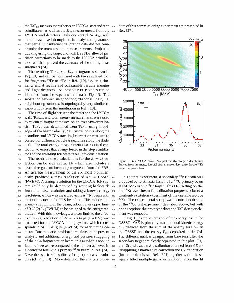
Figure 15: (a) LYCCA√∆E - Etot plot and (b) chargeZ distribution
derived from the energy loss∆E after the secondary target for the84Krfission fragment beam.
In another experiment, a secondary84Kr beam was821
produced by relativistic fission of a238U primary beam822
at 650 MeV/u on a9Be target. This FRS setting on sta-823
ble 84Kr was chosen for calibration purposes prior to a824
Coulomb excitation experiment of the unstable isotope825
88Kr. The experimental set-up was identical to the one826
of the 63Co test experiment described above, but with827
one exception: the prototype diamond ToF detector ele-828
ment was removed.829
In Fig. 15(a) the square root of the energy loss in the830
DSSSD√∆E is plotted versus the total kinetic energy831
Etot deduced from the sum of the energy loss∆E in832
the DSSSD and the energyEres deposited in the CsI.833
The different nuclear charges from bare ions after the834
secondary target are clearly separated in this plot. Fig-835
ure 15(b) shows theZ distribution obtained from∆E af-836
ter applying a momentum correction and aZ calibration837
(for more details see Ref. [30]) together with a least-838
square fitted multiple gaussian function. From this fit839
12

the charge resolution is calculated to be∆Z = 0.55.840
1.11 1.12 1.13 1.14 1.15
5000
5500
6000
6500
7000
7500
8000
-110
1
10
tot
γ
counts
E [M
eV
]
LYCCA
(a)
1.10
78 80 82 84 860
400
800
1200
1600
Cou
nts
per
chan
nel
datafit
(b)
Mass number A
Figure 16: (a) LYCCAEtot versusγLYCCA plot and (b) massA dis-tribution obtained from the distribution (a) by applying a momentumcorrection, a calibration, and background subtraction. Both plots arein prompt coincidence with incomingZ = 35 fragments using thepreceding FRS ion identification.
Masses are determined from the correlation between841
total kinetic energy and the time-of-flight. Figure 16(a)842
shows the mass identification plotEtot versusγLYCCA.843
The relativistic Lorentz factorγLYCCA is calculated from844
the ToF measured with LYCCA after the secondary tar-845
get. As a by-product of the84Kr beam also bromine iso-846
topes can be selected from the incoming beam cocktail847
with a gate onZ = 35 imposed on the FRS ion iden-848
tification. Following aZ = 35 selection in LYCCA849
as well, the capability of LYCCA to separate the dif-850
ferent Br isotopes after the secondary target is demon-851
strated. The two-dimensional distribution displayed in852
Fig. 16(a) is transformed into the mass spectrum shown853
in Fig. 16(b) by employing a momentum correction, a854
mass calibration, and subtraction of background. For855
a detailed description see Ref. [30]. The distribution856
is least-squares fitted with a multiple gaussian function857
with equal width values. The resulting mass resolution858
(FWHM) for massesA ∼ 80-85 yield∆A = 1.02.859
The preceding – and to some extent still preliminary860
– analyses provide the proof-of-principle of the LYCCA861
detection scheme. Both energy and timing resolutions862
of the various LYCCA detector elements have to work863
according to or even better than specifications to achieve864
the main characteristics of the set-up, namely865
• ∆Z/Z . 0.022 (Z . 26).866
• ∆Z/Z . 0.015 (Z . 36).867
• ∆A/A . 0.010 (A . 60).868
• ∆A/A . 0.012 (A . 80).869
In the framework of the presently ongoing870
PRESPEC-AGATA campaign at GSI, a compre-871
hensive performance commissining experiment has872
been performed recently, complemented with extensive873
pulser calibration data. This data is presently being874
analysed. Results concerning LYCCA performance will875
be subject to a forthcoming paper, detailing analysis876
procedures as well as achieved detector, proton number,877
and mass number resolutions [27].878
6. Summary and outlook towards HISPEC at FAIR-879
NUSTAR880
The concept, design and prototype developments for881
the FAIR-NUSTAR detector system LYCCA have been882
described. LYCCA aims to discriminate relativistic883
heavy-ion reaction products at typical energies of 100-884
300 MeV/u. Valuable and timely feedback on the LY-885
CCA design concept has been achieved during its early886
PRESPEC implementation of 12- and 16-module pro-887
totype versions of LYCCA at the GSI Helmholtzcentre888
for Heavy Ion Research in the years 2010-2014. With889
the basic LYCCA particle identification concept proven890
(cf. Sec. 5), further optimization on data analysis soft-891
ware algorithms is ongoing [27], and additional detec-892
tors and detector modules as well as electronics up-893
grades are foreseen towards the anticipated implemen-894
tation of the complete LYCCA device for HISPEC ex-895
periments.896
Concerning detectors, a very-large area plastic scin-897
tillator is being built to cover the approximate full 40-898
cm diameter of the downstream HISPEC beam pipe,899
i.e. the anticipated 26-module version of the LYCCA900
Wall. Concerning these telescopes of the LYCCA Wall,901
the aim is to be able to provide up to 30 CsI blocks each902
of the ‘short’ and ‘long’ version.903
In terms of read-out and processing electronics, the904
LYCCA Wall telescopes are going to be upgraded to905
already existing and commissioned sampling electron-906
ics modules: for the CsI(Tl)-PD part, the preamplifier907
13

signals are going to be digitized with some twenty 16-908
channel GSI-EE FEBEX3 cards [38] based on 14-bit909
50 MHz sampling ADCs. The DSSSDs are going to910
be handled by custom made front-end electronics de-911
veloped in the United Kingdom. It is based on a ap-912
plication specific integrated circuit design for the AIDA913
project [39]. Revised CFD-TDC concepts for the PMT914
signal processing of the large-area scintillators are to be915
investigated.916
Finally, LYCCA is going to be readily available to917
support physics-driven Super-FRS commissioning to-918
wards FAIR-NUSTAR, either stand-alone or together919
with other FAIR-NUSTAR detectors and activities.920
Acknowledgements921
LYCCA has been enabled by financial contributions922
of The Swedish Research Council, the German BMBF,923
and the United Kingdom STFC. The Lund group ac-924
knowledges essential additional financial support from925
The Royal Physiographic Society in Lund and The926
Crafoord Foundation in Lund. The LYCCA collabora-927
tion is grateful for the help of in particular GSI staff928
during the first LYCCA commissioning phase.929
References
[1] http://www.fair-center.eu/for-users/experiments/nustar.html[2] http://www.fair-center.eu/en/for-
users/experiments/nustar/experiments/hispecdespec.html[3] http://www.fair-center.eu/en/for-
users/experiments/nustar/experiments/super-frs.html[4] S. Akkoyunet al., Nuclear Instruments and Methods in Physics
Research Section A 668 (2012).[5] P. Boutachkovet al., to be published.[6] H. Geisselet al., Nuclear Instruments and Methods in Physics
Research Section B 70 (1992) 286.[7] H.J. Wollersheimet al., Nuclear Instruments and Methods in
Physics Research Section A 573 (2005) 637.[8] J. Eberthet al., Nuclear Instruments and Methods in Physics
Research Section A 369 (1996) 139.[9] R. Lozevaet al., Nuclear Instruments and Methods in Physics
Research Section A 562 (2006) 298.[10] M.J. Tayloret al., Nuclear Instruments and Methods in Physics
Research Section A 606 (2009) 589.[11] D. Rudolph et al., LYCCA Technical De-
sign Report, FAIR-NUSTAR, June 2008,available at http://www.nuclear.lu.se/
english/research/basic nuclear physics/nustar/
lycca/publications.[12] http://www.kns.com, Kulicke & Soffa, ManualKS4523 Digital
Bonder.[13] http://www.bluestarsilicones.com[14] http://www.amcrys-h.com[15] V. Avdeichikov et al., Nuclear Instruments and Methods in
Physics Research Section A 349 (1994) 216.[16] V. Avdeichikov et al., Nuclear Instruments and Methods in
Physics Research Section A 439 (2000) 158.
[17] V. Avdeichikov et al., Nuclear Instruments and Methods inPhysics Research Section A 484 (2002) 251.
[18] D. Bederedeet al., Nuclear Instruments and Methods in PhysicsResearch Section A 518 (2004) 15.
[19] A.S. Barann, Bachelor thesis, Lund University, 2013, unpub-lished.
[20] J. Taprogge, Bachelor thesis, Universitat zu Koln, 2009, unpub-lished.
[21] V. Avdeichikov et al., Nuclear Instruments and Methods inPhysics Research Section A 466 (2001) 427.
[22] V. Avdeichikov et al., Nuclear Instruments and Methods inPhysics Research Section A 501 (2003) 505.
[23] D.D. DiJulioet al., Nuclear Instruments and Methods in PhysicsResearch Section A 612 (2009) 127.
[24] R. Hoischenet al., Nuclear Instruments and Methods in PhysicsResearch Section A 654 (2011) 354.
[25] F. Schirruet al., J. Instrum.7, P05005 (2012).[26] R. Hoischen, PhD thesis, Lund University, LUNFD6/ (NFFR -
1032)/ 1-138/ (2011), ISBN 978-91-7473-090-6.[27] LYCCA Collaboration, to be published.[28] P. Moritz et al., Diamond and Related Materials10, 1765
(2001).[29] M.Ciobanuet al., IEEE Transactions on Nuclear Science58 4
(2011).[30] J. Taprogge, Masters thesis, Universitat zu Koln, 2011, unpub-
lished.[31] A. Wendt, PhD thesis, Universitt zu Koln, ISBN 978-3-8439-
0860-3 (2013).[32] Phillips Scientific, www.phillipsscientific.com/[33] ISEG GmbH, www.iseg-hv.com/[34] G. Pascoviciet al., WSEAS Trans. Circuits and Systems Vol.7
(6), 470 (2008).[35] B. Kuo and F. Golnaraghi, Automatic Control Systems, John
Willey & Sons Inc., 2003.[36] mesytec GmbH, www.mesytec.com/[37] L. Scruton, PhD thesis, University of York, 2013.[38] J. Hoffmann, N. Kurz, S. Loechner, S. Minami, W. Ott, I. Ru-
sanov, S. Voltz and P. Wieczorek, GSI Scientific Report 2011,GSI Report 2012-1 (2012).
[39] D. Braga, P.J. Coleman-Smith, T. Davinson, I.H. Lazarus,R.D. Page, and S. Thomas, IEEE Nucl. Sci. Symp. Conf. RecordN27-4 (2009); http://www.ph.ed.ac.uk/∼td/AIDA /.
14