the lee tunnel - secondary lining - water projects · pdf file wastewater treatment &...
TRANSCRIPT

this additional assurance, based on the principle that by controlling water ingress, water egress or exfiltration is equally mitigated.
The tunnel boring process produced a tunnel of precast concrete segmental rings; each ring is 1.7m wide and is made up of eight segments. Historically, the joints between segments are common paths for water ingress. Although the design of gaskets around segments has improved, the concerns are nonetheless valid as the effectiveness of gaskets could be compromised by other tunnelling activities. To ensure compliance with the specification for water ingress, and the structural integrity of the segments, a range of activities and parameters were closely monitored at all stages from design, fabrication and installation.
Deep underneath East London, tunnelling gangs are installing the last of the concrete lining to finish the Lee Tunnel. When Thames Water awarded the Lee Tunnel Contract to Morgan Sindall, VINCI Construction Grands Projets and Bachy Soletanche (MVB joint venture) in March 2010, it was the largest single contract ever let in
the UK water industry. The Lee Tunnel is the first of two tunnelling projects that form part of the London Tideway Improvements programme of works to enable Thames Water to achieve compliance with the Urban Wastewater Treatment Directive (UWWTD), as enacted in the Urban Wastewater Treatment Regulations 1994. The £711m Lee Tunnel project is now in its final year. The tunnel boring machine bored through 7km of material and broke through into the reception shaft at the Abbey Mills Sewage Pumping Station site over a year ago. The civil works are nearly complete; mechanical, electrical and ICA installation are well underway; and the secondary lining to the tunnel is almost complete. This article focuses on the secondary lining of the tunnel.
PurposeThe purpose of the secondary lining is to provide two basic functions:
• To compliment the primary lining to mitigate water ingress.• To provide a structurally competent, durable and smooth
bore for the hydraulic performance of the tunnel.
The tunnel was constructed at an average depth of 75m in chalk in the lower aquifer, with up to 6 bar groundwater pressure. To effectively allay the short term environmental concerns around potential groundwater contamination, assurance against water ingress into the tunnel was required. The secondary lining provides
www.WaterProjectsOnline.com Wastewater Treatment & Sewerage
Page 1 of 6 UK Water Projects 2015
The Lee Tunnel - Secondary Liningsecondary lining mitigates water ingress and provides a structurally competent,
durable and smooth bore for the hydraulic performance of the tunnelby Morgan Anamoah
The shutter - Courtesy of Thames Water

mvb
Morgan Sindall, VINCI Construction Grands Projets and Bachy Soletanche are working together as MVB, combining world-class expertise, together with CH2M Hill, to deliver the Lee Tunnel for Thames Water. An essential step in providing the capital with a 21st century sewerage system.
Lee Tunnel partnershipbrings success
www.mvbjv.co.uk
The secondary lining of Thames Water’s four-mile long Lee Tunnel project is now complete. This milestone marks the end of all the civil works in the 75 metre deep tunnel.
www.WaterProjectsOnline.com Wastewater Treatment & Sewerage
Page 3 of 6 UK Water Projects 2015
Design considerationsFollowing discussions between the contractor, the project manager and the client, and a review of applicable technical standards and reports, a cast-in-place steel fibre reinforced concrete was selected. Using traditional steel reinforcing bar has significant durability disadvantages in terms of abrasion, corrosion, crack distribution and crack widths.
To provide data sufficient to advance the design of the fibre reinforced concrete, a series of tests and trials were completed at the accredited project laboratory at Beckton, and at the facilities at the Building Research Establishment near Watford. The concrete mix, fibre type, fibre dosage, and additive requirements for optimum workability were some of the technical challenges that had to be addressed. Trials to define concrete placement techniques were also undertaken: pump capacity, optimum length of pumping, flotation strength, material segregation, curing and surface finish.
The concrete was eventually specified as follows: Dramix 5D steel fibres at 40kg/m3; workability to be retained for four hours, but should gain early strength to enable prompt and rapid striking of shutters; the concrete to flow 15m without segregation; minimum cracking; 120-year design life. Detailed site trials continued for a further six months. The trials highlighted issues with pump capacity, fibre balling, distribution valve design and pump pipe line wear which had to be resolved.
The tunnel alignment included both left and right hand curves of various radii. To negotiate the curves, a study was undertaken to derive the optimum shutter length; 10.2m maximum long,straight shutters (or sections of shutters) were selected.
The specified nominal thickness of the secondary lining was 300mm. Following the detailed testing and in particular the full scale beam tests, the designer calculated that a minimum of 250mm
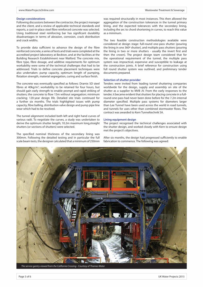
The service gantry viewed from the California Crossing - Courtesy of Thames Water
was required structurally in most instances. This then allowed the aggregation of the construction tolerances in the tunnel primary lining, and the expected tolerances with the secondary lining, including the arc to chord shortening in curves, to reach this value as a minimum.
The two feasible construction methodologies available were considered at design stage: full-round one-pass shutter (pouring the lining in one 360o shutter), and multiple pass shutters (pouring the lining in two or more shutters - usually the invert first and then the crown). The project design team considered that for the operational requirement of the tunnel, the multiple pass system was impractical, expensive and susceptible to leakage at the construction joints. A brief reference for construction using full round shutter system was outlined, and preliminary tender documents prepared.
Selection of shutter providerTenders were invited from leading tunnel shuttering companies worldwide for the design, supply and assembly on site of the shutter as a supplier to MVB JV. From the early responses to the tender, it became evident that shutters for placing concrete in a full-round-one-pass had never been done before for the 7.2m internal diameter specified. Multiple pass systems for diameters larger than Lee Tunnel have been used across the world in road tunnels, and tunnels for uses other than combined stormwater flows. The contract was awarded to Kern Tunneltechnik SA.
Lining equipment design The project recognised the technical challenges associated with the shutter design, and worked closely with Kern to ensure design met the project’s objectives.
After six months, the design had progressed sufficiently to enable fabrication to commence. The following was agreed:
www.WaterProjectsOnline.com Wastewater Treatment & Sewerage
Page 4 of 6 UK Water Projects 2015
• To meet programme, and ensure compliance with the stringent works specification, 2 (No.) 30.6m long shutters were provided. Each shutter comprised 3 (No.) 10.2m straight modules bolted up square for straight alignment. For curves, make-up taper sections were used between the modules. The two shutters would work together in a ‘hit and miss’ format.
• To help control cracking due to drying shrinkage, each shutter was to be coupled with a curing gantry that provided aqueous aerosol to control hydration.
• For pumping in concrete and monitoring progress, a number of injection ports and observation windows were provided; electric external vibrators were strategically located to ensure optimum efficiency. Concrete distribution with hydraulic valves/switches made sure all injection ports were accessible. Pressure monitors and release valves were placed at the crown to control the filling process.
• The leading shutter was to have stop ends at both ends. To constrain the power demand, they were designed to be semi-hydraulic with some manual operation.
• To avoid grout loss, and take up tolerances within the tunnel build, the butts of the stop-end were provided with suitably sized gaskets.
• The full round shutters were to be made up of two independent sections: invert and top vault.
Secondary lining equipment descriptionTo facilitate the secondary lining process, the following equipment was provided:
The invert shutter: The invert shutter is made up of two sections of curved shutter connected with hinges and pins. When fully formed and stabilised with spud legs, the invert shutter is 5m wide, and 1,300mm high. The hinge and pinion connection allows the shutter to fold on itself, when lifted with the invert traveller. This allows the invert to be transported through the tunnel and the shutters to progress forward. The invert shutter has two pairs of rail tracks: one at a low level, the other high level. The narrower gauge low level track is for the invert traveller system, while the higher wide gauge track supports the vault traveller.
Invert traveller: To strike, transport and set-up the invert sections an ‘invert traveller’ is provided. The traveller consist of two pairs of portal frames with telescopic legs. Each pair of legs has a motor that provides forward and reverse movement. The inner pairs have double flanged rail wheels; and the outer pairs inclined ‘vulkollan’ wheels for travelling on the tunnel segments.
Vault shutters: Two shutters were provided; Shutter 1 is made up of 3 (No.) 10.2 m long identical sub-shutters with stop ends at both ends; Shutter 2, also made up of 1 (No.) 10.2 m long sub-shutter, but with slightly shorter leading and trailing end sub-shutters. The end sub-shutters are 700mm shorter, making them 9.5m long.
To secure the shutters in place, side spud bars are used apart from the roof/crown area where flotation loads are most significant. In this area a support system, integral with the portal frame, is used to transfer the loads on to the invert rails.
Invert traveller: Each shutter had a traveller system for movement. Each sub-shutter has a pair of portal frames with telescopic legs on double flanged metal wheels. Each wheel is connected to a motor; and allows both forward and reverse movement along the high level rails on the invert shutter. Maximum travelling speed is about 7m/minute.
Due to its size, there are two levels of working platforms, provided with parapets/guard rails, and stairs to reach all the relevant areas during operation.
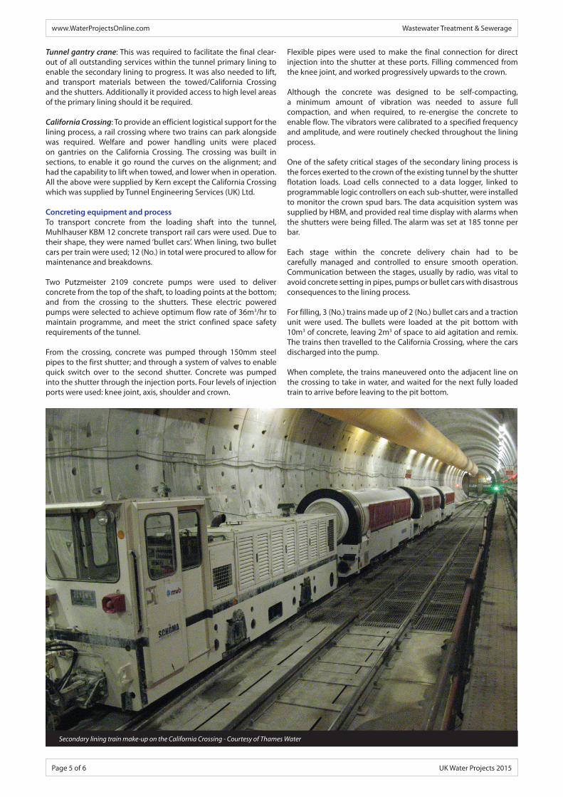
Invert traveller - Courtesy of Thames Water
View through shutter at invert shutter level - Courtesy of Thames Water
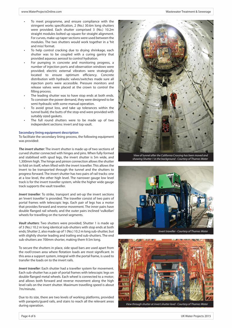
View of tunnel after the California Crossing has been moved and showing Shutter 1 in the background - Courtesy of Thames Water
www.WaterProjectsOnline.com Wastewater Treatment & Sewerage
Page 5 of 6 UK Water Projects 2015
Tunnel gantry crane: This was required to facilitate the final clear-out of all outstanding services within the tunnel primary lining to enable the secondary lining to progress. It was also needed to lift, and transport materials between the towed/California Crossing and the shutters. Additionally it provided access to high level areas of the primary lining should it be required.
California Crossing: To provide an efficient logistical support for the lining process, a rail crossing where two trains can park alongside was required. Welfare and power handling units were placed on gantries on the California Crossing. The crossing was built in sections, to enable it go round the curves on the alignment; and had the capability to lift when towed, and lower when in operation. All the above were supplied by Kern except the California Crossing which was supplied by Tunnel Engineering Services (UK) Ltd.
Concreting equipment and processTo transport concrete from the loading shaft into the tunnel, Muhlhauser KBM 12 concrete transport rail cars were used. Due to their shape, they were named ‘bullet cars’. When lining, two bullet cars per train were used; 12 (No.) in total were procured to allow for maintenance and breakdowns.
Two Putzmeister 2109 concrete pumps were used to deliver concrete from the top of the shaft, to loading points at the bottom; and from the crossing to the shutters. These electric powered pumps were selected to achieve optimum flow rate of 36m3/hr to maintain programme, and meet the strict confined space safety requirements of the tunnel.
From the crossing, concrete was pumped through 150mm steel pipes to the first shutter; and through a system of valves to enable quick switch over to the second shutter. Concrete was pumped into the shutter through the injection ports. Four levels of injection ports were used: knee joint, axis, shoulder and crown.
Flexible pipes were used to make the final connection for direct injection into the shutter at these ports. Filling commenced from the knee joint, and worked progressively upwards to the crown.
Although the concrete was designed to be self-compacting, a minimum amount of vibration was needed to assure full compaction, and when required, to re-energise the concrete to enable flow. The vibrators were calibrated to a specified frequency and amplitude, and were routinely checked throughout the lining process.
One of the safety critical stages of the secondary lining process is the forces exerted to the crown of the existing tunnel by the shutter flotation loads. Load cells connected to a data logger, linked to programmable logic controllers on each sub-shutter, were installed to monitor the crown spud bars. The data acquisition system was supplied by HBM, and provided real time display with alarms when the shutters were being filled. The alarm was set at 185 tonne per bar.
Each stage within the concrete delivery chain had to be carefully managed and controlled to ensure smooth operation. Communication between the stages, usually by radio, was vital to avoid concrete setting in pipes, pumps or bullet cars with disastrous consequences to the lining process.
For filling, 3 (No.) trains made up of 2 (No.) bullet cars and a traction unit were used. The bullets were loaded at the pit bottom with 10m3 of concrete, leaving 2m3 of space to aid agitation and remix. The trains then travelled to the California Crossing, where the cars discharged into the pump.
When complete, the trains maneuvered onto the adjacent line on the crossing to take in water, and waited for the next fully loaded train to arrive before leaving to the pit bottom.
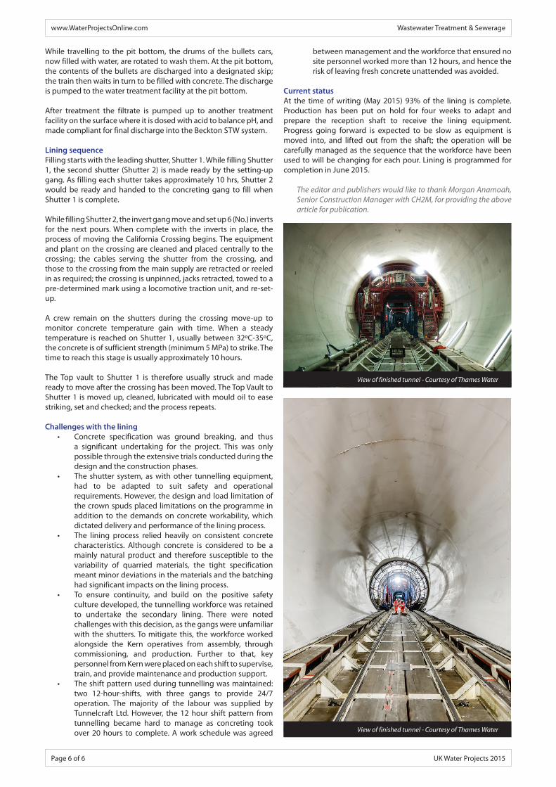
Secondary lining train make-up on the California Crossing - Courtesy of Thames Water
www.WaterProjectsOnline.com Wastewater Treatment & Sewerage
Page 6 of 6 UK Water Projects 2015
While travelling to the pit bottom, the drums of the bullets cars, now filled with water, are rotated to wash them. At the pit bottom, the contents of the bullets are discharged into a designated skip; the train then waits in turn to be filled with concrete. The discharge is pumped to the water treatment facility at the pit bottom.
After treatment the filtrate is pumped up to another treatment facility on the surface where it is dosed with acid to balance pH, and made compliant for final discharge into the Beckton STW system.
Lining sequenceFilling starts with the leading shutter, Shutter 1. While filling Shutter 1, the second shutter (Shutter 2) is made ready by the setting-up gang. As filling each shutter takes approximately 10 hrs, Shutter 2 would be ready and handed to the concreting gang to fill when Shutter 1 is complete.
While filling Shutter 2, the invert gang move and set up 6 (No.) inverts for the next pours. When complete with the inverts in place, the process of moving the California Crossing begins. The equipment and plant on the crossing are cleaned and placed centrally to the crossing; the cables serving the shutter from the crossing, and those to the crossing from the main supply are retracted or reeled in as required; the crossing is unpinned, jacks retracted, towed to a pre-determined mark using a locomotive traction unit, and re-set-up.
A crew remain on the shutters during the crossing move-up to monitor concrete temperature gain with time. When a steady temperature is reached on Shutter 1, usually between 32oC-35oC, the concrete is of sufficient strength (minimum 5 MPa) to strike. The time to reach this stage is usually approximately 10 hours.
The Top vault to Shutter 1 is therefore usually struck and made ready to move after the crossing has been moved. The Top Vault to Shutter 1 is moved up, cleaned, lubricated with mould oil to ease striking, set and checked; and the process repeats.
Challenges with the lining• Concrete specification was ground breaking, and thus
a significant undertaking for the project. This was only possible through the extensive trials conducted during the design and the construction phases.
• The shutter system, as with other tunnelling equipment, had to be adapted to suit safety and operational requirements. However, the design and load limitation of the crown spuds placed limitations on the programme in addition to the demands on concrete workability, which dictated delivery and performance of the lining process.
• The lining process relied heavily on consistent concrete characteristics. Although concrete is considered to be a mainly natural product and therefore susceptible to the variability of quarried materials, the tight specification meant minor deviations in the materials and the batching had significant impacts on the lining process.
• To ensure continuity, and build on the positive safety culture developed, the tunnelling workforce was retained to undertake the secondary lining. There were noted challenges with this decision, as the gangs were unfamiliar with the shutters. To mitigate this, the workforce worked alongside the Kern operatives from assembly, through commissioning, and production. Further to that, key personnel from Kern were placed on each shift to supervise, train, and provide maintenance and production support.
• The shift pattern used during tunnelling was maintained: two 12-hour-shifts, with three gangs to provide 24/7 operation. The majority of the labour was supplied by Tunnelcraft Ltd. However, the 12 hour shift pattern from tunnelling became hard to manage as concreting took over 20 hours to complete. A work schedule was agreed
between management and the workforce that ensured no site personnel worked more than 12 hours, and hence the risk of leaving fresh concrete unattended was avoided.
Current statusAt the time of writing (May 2015) 93% of the lining is complete. Production has been put on hold for four weeks to adapt and prepare the reception shaft to receive the lining equipment. Progress going forward is expected to be slow as equipment is moved into, and lifted out from the shaft; the operation will be carefully managed as the sequence that the workforce have been used to will be changing for each pour. Lining is programmed for completion in June 2015.
The editor and publishers would like to thank Morgan Anamoah, Senior Construction Manager with CH2M, for providing the above article for publication.
View of finished tunnel - Courtesy of Thames Water
View of finished tunnel - Courtesy of Thames Water