water supply and sewerage approved products manual ... · last updated feb 2006 water supply and...
TRANSCRIPT

Last updated Feb 2006
Water Supply and Sewerage Approved Products Manual - February 2006
Gravity Sewerage Products - Maintenance Structures
Section SGO 01

MAINTENANCE STRUCTURES CONTENTS
GRAVITY SEWERAGE PRODUCTSSection SGO 01 Power and Water – Water Supply and Sewerage Approved Products Manual – February 2006 TOC
SPECIFICATIONS ASGO 01-S1 PRECAST CONCRETE MAINTENANCE HOLES - SHAFT SEGMENTS ASGO 01-S1A PRECAST CONCRETE MAINTENANCE HOLES (INTERIM) BSGO 01-S1B PRECAST CONCRETE MAINTENANCE HOLES CSGO 01-S2 PLASTIC MAINTENANCE HOLES DSGO 01-S3 MAINTENANCE HOLE ACCESS COVERS AND FRAMES ESGO 01-S4 PLASTIC MAINTENANCE SHAFTS FSGO 01-S5 MAINTENANCE SHAFT ACCESS COVERS AND FRAMES GSGO 01-S6 LIGHT DUTY INSPECTION OPENING COVERS AND FRAMES HSGO 01-S7 HEAVY DUTY INSPECTION OPENING COVERS AND FRAMES JSGO 01-S8 STEEL LADDERS KSGO 01-S9 GRP LADDERS LSGO 01-S10 PLASTIC ENCAPSULATED STEP IRONS MSGO 01-S11 EPOXY FOR JOINTING/REPAIR OF CONCRETE MH’S N
MH COVERS & FRAMES 1RECTANGULAR GASTIGHT RECESSED COVER 900 X 600 1CIRCULAR GASTIGHT RECESSED COVER DN 600 1RECTANGULAR WATERTIGHT RECESSED COVER 900 X 600 2CIRCULAR WATERTIGHT RECESSED COVER DN 600 2CIRCULAR GASTIGHT SOLID TOP COVER DN 600 2CIRCULAR WATERTIGHT SOLID TOP COVER DN 600 3
PRECAST CONCRETE MAINTENANCE HOLES 4SHAFT SEGMENTS (TO SPEC SGO 01-1A) 4MAKE-UP RINGS 4TAPERED MAKE-UP RINGS 4BASES 5COVER SLABS 5
MAINTENANCE SHAFTS 6IN-LINE CHAMBERS 6ELBOW CHAMBERS 6TERMINAL CHAMBERS 6SHORT RADIUS RISER BENDS 7RISER JUNCTIONS 7RISER BAYONET CAP 7CIRCULAR WATERTIGHT SOLID TOP COVER DN 375 7COVER SLABS 8
INSPECTION OPENINGS 9LIGHT DUTY I.O. 9LIGHT DUTY I.O. WITHIN CONCRETE SURROUND 9HEAVY DUTY I.O. 9HEAVY DUTY I.O. WITHIN CONCRETE SURROUND 9
MH ANCILLARIES 10LADDERS 10PLASTIC ENCAPSULATED STEP IRONS 10
MH JOINTING & REPAIR 11EPOXIES 11

MAINTENANCE STRUCTURES SPECIFICATIONS
GRAVITY SEWERAGE PRODUCTSSection SGO 01 Power and Water – Water Supply and Sewerage Approved Products Manual – February 2006 Page A
SPECIFICATIONS
SGO 01-S1 PRECAST CONCRETE MAINTENANCE HOLES - SHAFT SEGMENTSSTANDARD AS 3735:2001 Concrete structures for retaining liquids
AS 4058:1992 Precast concrete pipes (pressure and non-pressure)(pipe shaft segments)
DRAWING Power and Water: W2-2-02, W2-2-01D WSA 02: SEW-1300
DESIGN Concrete constituents and reinforcement cover have been chosen to provide acceptablepreformance. Maintenance holes within the Northern Territory are: mostly exposed internally to stale sewage due to high ambient temperatures and under
alternate wet and dry (condensation, splashing or washing) conditions this equates toexposure classification D in Table 4.1 of AS 3735. This condition is exacerbated by highsulphate levels present in water supplies sourcing ground water.
Exposed externally under worst case conditions to ground water in sandy soils, which maybe saline with resistivity < 10Ω.m or having sulphates > 6000 ppm; this equates toexposure classification C to Table of AS 3735 supplement 1
Concrete cover to reinforcement for pipe shaft segments exceeds minimum requirements of AS4058 (Table 3.3 10 mm) and is governed by the available manufacturer’s pipe moulds.Reinforcing in shaft segments is to be circular, not elliptical. DN1050 & 1200 shaft segments towithstand ultimate loads 63 kN/m and 69 kN/m respectively.
MATERIALS Concrete:Shaft segments: To AS 4058 section 2, concrete mix design sufficient to achieve
Class 2 load classificationCement:: Type GP cement to AS 3972 for normal class concrete. Type SR
cement for special class concreteAggregate: To AS 2758.1, no durability exposure classification specified, no
maximum water absorption of coarse aggregate specifiedReinforcement: Welded wire fabric, wire and bars to AS/NZS 4671Reo supports: Stainless steel grade to ASTM A 276 grade 304 or plasticJoint seal: Approved epoxyCoatings: Approved high build solventless epoxy (2 coats min.) where specified
INTERNALSURFACE
Appearance: To AS 4058 clause 3.3.3 and 3.3.4, free from defects that wouldimpair strength or serviceability
Smoothness: To AS 4058 clause 3.3.3 equivalent to a steel trowel finish
SEGMENT JOINTS Flush jointed ends with epoxy mortar jointing
REO COVER Internally: 27 mm1 (min spun or rolled pipeshaft segments)
Externally: 27 mm1 (min spun or rolled pipeshaft segments)
Note 1: Actual cover exceeds minimum cover
INTERNAL DIAM. Shaft Segments: 1050 mm and 1200 mm nominal minimum
MARKINGS Manufacturer’s name or registered trademarkDate and place of manufactureMaximum mass of pipe in kilograms.For pipes the nominal size and load classAustralian Standard number, i.e. AS 4058 (pipe shaft segments)(if product certification obtained)Product certification mark (if product certification obtained), e.g. StandardsMarkInternal and external cover
MARKING METHOD Clearly and indelibly marked in an easily visible location.
WITHDRAWN

MAINTENANCE STRUCTURES SPECIFICATIONS
GRAVITY SEWERAGE PRODUCTSSection SGO 01 Power and Water – Water Supply and Sewerage Approved Products Manual – February 2006 Page B
SGO 01-S1A PRECAST CONCRETE MAINTENANCE HOLES (INTERIM)STANDARD AS 4198:1994 Precast concrete access chambers for sewerage applications
AS 3735:2001 Concrete structures for retaining liquids
DESIGN Concrete constituents and reinforcement cover have been chosen to provide improvedperformance. Maintenance holes within the Northern Territory are: mostly exposed internally to stale sewage due to high ambient temperatures and under
alternate wet and dry (condensation, splashing or washing) conditions this equates toexposure classification D in Table 4.1 of AS 3735. This condition is exacerbated by highsulphate levels present in water supplies sourcing ground water.
Exposed externally under worst case conditions to ground water in sandy soils, which maybe saline with resistivity < 10Ω.m or having sulphates > 6000 ppm; this equates toexposure classification C to Table 4.1 of AS 3735 supplement 1
Concrete cover to reinforcement is derived from Table 4.3 of AS 3735. The cover decreaseswith increased concrete strength so the highest strength concrete is to be adopted to minimisecover. Reinforcing in shaft segments is to be circular, not elliptical.
All components to be designed to withstand an ultimate load test of 210 kN.
MATERIALS Concrete: Concrete to AS 1379/AS 3735 with compressive strength (f’c) of 50 MPamin at 28 days, nominal slump 80 mm, cement content of 400 kg/m3 min.Water absorption of 6.5% maximum to AS 4198. Water/cement ratio not toexceed 0.5 and maximum drying shrinkage at 56 days of 700 x 10-6.
Cement: Generally Type GP cement to AS 3972 or where specified Type SRcement to AS 3972.
Aggregate: Aggregate to AS 2758.1, durability for exposure classification C andmaximum water absorption of 2.5%. Coarse aggregate with maximumparticle size of 20 mm.
Reinforcement: Welded wire fabric, wire and bars to AS/NZS 4671Reo supports: Stainless steel grade to ASTM A 276 grade 304, or plasticJoint seal: Approved epoxyCoatings: Approved high build solventless epoxy (2 coats min.) where specified
INTERNALSURFACE
Appearance: To class 2X finish shown in photograph in Appendix B of AS 3610 withblowhole depth not to exceed 5 mm.
Smoothness: Hand finish as necessary to remove abrasive roughness. Do not bag.
SEGMENT JOINTS Flush jointed with epoxy mortar jointing
REO COVER Internally: 45 mm (min) Externally: 45 mm (min)
INTERNAL DIAM. Shaft Segments: 1100 mm nominal minimum
MARKINGS Manufacturer’s name or registered trademark, or bothFor unreinforced components, ‘U’. For reinforced components, ‘R’.Date and place of manufacture, or the manufacturer’s traceability code incorporating dateMaximum mass of component in kilograms.The Australian Standard number, i.e. AS 4198 (if product certification obtained)Product certification mark (if product certification obtained) e.g. StandardsMarkFor components using Type SR cement, ‘SR’
MARKING METHOD Clearly marked in an easily visible location. Marking of cover slab to be on the top surface. Majortop components to have permanent and indelible marking on the inside surface. Othercomponents need not have permanent marking.

MAINTENANCE STRUCTURES SPECIFICATIONS
GRAVITY SEWERAGE PRODUCTSSection SGO 01 Power and Water – Water Supply and Sewerage Approved Products Manual – February 2006 Page C
SGO 01-S1B PRECAST CONCRETE MAINTENANCE HOLES
STANDARD AS 4198:1994 Precast concrete access chambers for sewerage applicationsAS 3735:2001 Concrete structures for retaining liquids
DESIGN Concrete constituents and reinforcement cover have been chosen to minimise the rate ofconcrete corrosion. Maintenance holes within the Northern Territory are: mostly exposed internally to stale sewage due to high ambient temperatures and under
alternate wet and dry (condensation, splashing or washing) conditions this equates toexposure classification D in Table 4.1 of AS 3735. This condition is exacerbated by highsulphate levels present in water supplies sourcing ground water.
exposed externally under worst case conditions to ground water in sandy soils, which maybe saline with resistivity < 10Ω.m or having sulphates > 6000 ppm; this equates toexposure classification C to Table 4.1 of AS 3735 supplement 1
Concrete cover to reinforcement is derived from Table 4.3 of AS 3735. The cover decreaseswith increased concrete strength so the highest strength concrete is to be adopted to minimisecover. Reinforcing in shaft segments is to be circular, not elliptical.
All components to be designed to withstand an ultimate load test of 210 kN.
MATERIALS Concrete: Concrete to AS 1379/AS 3735 with compressive strength (f’c ) of 50 Mpamin at 28 days, nominal slump 80 mm, cementitious material content of400 kg/m3 min. Water absorption of 6.5% maximum to AS 4198.Water/cement ratio not to exceed 0.5 and maximum drying shrinkage at 56days of 700 x 10-6.
Cement: Type SR (sulphate resisting) blended cement to AS 3972Aggregate: To AS 2758.1, durability for exposure classification C and maximum water
absorption of 2.5%. Calcareous coarse aggregate with maximum particlesize of coarse aggregate 20 mm.
Reinforcement: Welded wire fabric, wire and bars to AS/NZS 4671Reo supports: Stainless steel grade to ASTM A 276 grade 304 or plasticJoint seal: Approved epoxyCoatings: Approved high build solventless epoxy (2 coats min.) where specified
INTERNALSURFACE
Appearance: To class 2X finish shown in photograph in Appendix B of AS 3610 withblowhole depth not to exceed 5 mm.
Smoothness: Hand finish as necessary to remove abrasive roughness. Do not bag.
SEGMENT JOINTS Flush jointed with epoxy mortar jointing
REO COVER Internally: 45 mm (min) Externally: 45 mm (min)
INTERNAL DIAM. Shaft segments: 1100 mm nominal minimum
MARKINGS Manufacturer’s name or registered trademark, or bothFor unreinforced components, ‘U’. For reinforced components, ‘R’.Date and place of manufacture, or the manufacturer’s traceability code incorporating dateMaximum mass of component in kilograms.The Australian Standard number, i.e. AS 4198 (if product certification obtained)Product certification mark (if product certification obtained), e.g. Standardmark
MARKING METHOD Clearly marked in an easily visible location. Marking of cover slab to be on the top surface. Majortop components to have permanent and indelible marking on the inside surface. Othercomponents need not have permanent marking.
UNDERREVIEW

MAINTENANCE STRUCTURES SPECIFICATIONS
GRAVITY SEWERAGE PRODUCTSSection SGO 01 Power and Water – Water Supply and Sewerage Approved Products Manual – February 2006 Page D
SGO 01-S2 PLASTIC MAINTENANCE HOLES
STANDARD DIN 19537-3:90 Prefabricated high density polyethylene manholes for use in seweragesystems; dimensions and technical delivery conditions
DIN 19565-5:90 Prefabricated glass fibre reinforced plastic (UP-GF) manholes for usein sewerage systems; dimensions and technical delivery conditions
ASTM D3753-81(86) Glass-Fibre-Reinforced Polyester Manholes
DESIGN Plastic maintenance holes are to be of circular cross section only and are to be of appropriatering stiffness, shape and design to resist: External hydrostatic pressures up to 6m pressure head to invert without buckling Overburden loads from the cover slab and traffic or maintenance vehicles without distortion
or crushing. External pressure on placement of any surrounding or encasing concrete Surrounding soil differential loading, if not concrete encased (uniform compaction of soil
about a plastic maintenance hole can be difficult to achieve and can lead to localiseddistortion of the ring cross section)
Flotation (Lightweight plastic maintenance holes may require to be anchored into theground using concrete, depending on the level of the water table above invert. Soil over themaintenance hole’s pipeline connection stubs will provide some flotation resistance.)
Segmental component structure of plastic MH’s for component field assembly or incorporatingelastomeric sealing segments is not permitted as joints; diminish the structure’s ability to support overburden loads; and can be a source of leakage due to uneven soil pressures causing differential distortion of
adjacent segments.
All plastic maintenance holes are to be subject to an external hydrostatic pressure test beforeacceptance (in a test tank with appropriate restraint to prevent flotation).
MATERIALS GRP to AS 3571 and AS 2634Polyethylene to AS/NZS 4131, Type 80B or 80C
INTERNAL DIAM. 1050 mm and 1200 mm
MARKINGS Manufacturer’s name or registered trademark, or bothDate and place of manufacture, or the manufacturer’s traceability code incorporating dateMaximum mass of component in kilograms
MARKING METHOD Clearly marked in an easily visible location on the inside wall. Lettering height 20 mm minimum
USE LIMITS To be defined on application for approvalUse of polyethylene products north of Alice Springs not preferred due to risk of termite damage

MAINTENANCE STRUCTURES SPECIFICATIONS
GRAVITY SEWERAGE PRODUCTSSection SGO 01 Power and Water – Water Supply and Sewerage Approved Products Manual – February 2006 Page E
SGO 01-S3 MAINTENANCE HOLE ACCESS COVERS AND FRAMES
STANDARD AS 3996: 1992 Metal access covers, road grates and frames
DRAWING Power and Water: W2-2-02 WSA 02: SEW-1308
DESIGN Unit (cover and frame) to withstand loads applicable for the location of use as defined by theclass. Mating surfaces of cover and frame to be machined to provide; even and secure seating of cover in frame; permanent elimination of movement or dislodgment by normal traffic; and a watertight or gastight seal as required when coated with 0.25 mm grease or equivalent.
Cover to include lifting holes with preferred dimensions as given in AS 3996 figure 3.1 andclockwise key engagement. Lifting keyholes to be fitted with removable plastic plugs toprevent material ingress. Recessed or infill type covers to have cross webbed, cellularconstruction not less than 15 mm deep to allow for concrete infill extending to within 25 mm ofthe outside of the frame at surface level but excepting keyhole housings and manufacturer’sname or identification mark. Clearance between cover and frame and between covers inmultiple cover units not to exceed 3 mm as measured at the cover surface. Concrete not to beproud of the metal top of the unit by more than 1 mm. Clearance between a straight edge andthe top of a unit not to exceed 3 mm at any position that the straight edge is laid. Covers to beinterchangeable in any frame from that manufacturer.
MATERIALS Cover & frame: Ductile cast iron grade AS 1831/500-7 or 600-3Grey cast iron grade AS 1830/T220
Frame bolts: Stainless steel to ASTM A276 grade 316Concrete infill: Concrete to AS 1379 with minimum compressive strength of 32 Mpa at 28
days and minimum cement content of 400 kg/m3
Coating: Bitumen to BS 3416 type II where cold applied and to BS 4147 type I gradeC where hot appliedTar to BS 4164
ALLOWED CLASSESAND FINISH
Class D: Road reserves including the verge, nature strip or footpath and walkways ormalls. Surface of cover to be flush with surrounding finished surface level.
Class B: Other areas than specified for class D. Surface of cover 150 mm minimum abovethe surrounding finished surface level.
Class C: Non-urban areas where specified
Rectangular (900 mm x 600 mm clear opening): Class B, C and DALLOWED SHAPESAND CLASS LIMITS Circular (600 mm diameter clear opening): Class B and D
ALLOWED TYPES Sewerage: Gastight sealed recessed or solid topNon-sewerage (valve pits etc): Watertight sealed recessed or solid top
MARKINGS Manufacturer’s name or registered trademarkYear of manufactureCode indicating place of manufactureRegister or marking to show orientation of cover in frame (if specific orientation is essential).Class and type of unit, e.g. Class D, Watertight sealedApproximate maximum mass of the unit (cover & frame) including concrete, visible from aboveThe Australian Standard number, i.e. AS 3996Product certification mark, e.g. StandardsMark
MARKING METHOD Legible marking. Items 4) and 5) to be permanent.
USE LIMITS Solid top covers are required to be bolted to the maintenance hole.Use of cover shapes is specified on Power and Water standard drawings.

MAINTENANCE STRUCTURES SPECIFICATIONS
GRAVITY SEWERAGE PRODUCTSSection SGO 01 Power and Water – Water Supply and Sewerage Approved Products Manual – February 2006 Page F
SGO 01-S4 PLASTIC MAINTENANCE SHAFTSSTANDARD AS/NZS 4999 (Int) :2003 PVC-U Maintenance Shafts
WSA 102 : Polyethylene Maintenance Shafts
DRAWING Power and Water: W2-2-07, W2-2-08, W2-1-09 WSA 02: SEW-1313 to SEW-1317
DESIGN Plastic maintenance shafts are to comprise a base chamber and a pipe riser. The riser mayinclude junction fittings for property connections. The riser is to be adjustable to within 0.5° ofvertical using fine angle bends (1 to 5°) at the chamber/riser connection. Plastic maintenanceshafts are to be of a design to permit unimpeded access of maintenance equipment (i.e. jetters,cutters, sealing plugs, cameras, etc.) into the pipeline and allow unhindered operation ofequipment from the surface. Internal surfaces of joints are to be smooth. The base chamber isto be of appropriate stiffness, shape and design to resist: External hydrostatic pressures up to 6 m pressure head to invert without buckling Soil loads up to 6 m depth to invert without cracking or significant deformation (negative or
inward side deflection and inward curvature at any point is not allowed) Flotation
MATERIALS Base chamber: PVC pipe sections to AS/NZS 1260 with polyester resin impregnatedglass fibre reinforcement of fabricated jointsPolyethylene to AS/NZS 4131, Type 80B or 100 or other approvedcompound with fusion jointing of segments to approved procedurePolypropylene to AS/NZS 5065 or ISO 8773
Riser components: PVC pipes and fittings to AS/NZS 1260 with polyester resin impregnatedglass fibre reinforcement of fabricated joints, pipe stiffness class SN8
Sewer joint seal: Approved elastomer to AS 1646Riser joint seals: Solvent cement to AS/NZS 3879 (Junction fitting on the riser may
alternatively use an elastomeric seal to AS 1646)
DIMENSIONS Riser: DN 225Chamber: Structural design dependent
JOINTING Chamber to sewer: Spigot-socket rubber ring jointRiser to chamber: PVC riser to PVC chamber: spigot-socket solvent cement joint
PVC riser to PE chamber: mechanical, threaded or flanged
CONNECTIONS VC pipeline systems to EN 295 and AS 1741Plain wall and ribbed PVC pipeline systems to AS/NZS 1260
Manufacturer’s name or registered trademark, or bothComponent description,e.g. 150 x 150 x 15 deg MSEL (chamber with 150∅ end connections and a 15 degree elbow)
COMPONENTMARKINGS
Material designation, e.g. ‘PVC’ or ‘PE’Date of manufacture in the form 980721 (year, month, day)Identification of the place of manufactureDirection of flow (chamber marking only)
MARKING METHOD Durably marked
USE LIMITS DN 150 and DN225 maintenance shafts are approvedDo not use maintenance shafts where depth to invert exceeds 3m, unless specific projectapproval has been granted by the Water Engineering section of Power and WaterOnly use maintenance shafts adjacent to maintenance holes.Do not connect branch sewers at maintenance shaftsDo not use a maintenance shaft as the first access upstream of an in-line gas trap.Do not use maintenance shafts at discharge points of pumping mains.Do not connect property connections to the chamberDo not connect more than two property connections to the riser and connect only residences.

MAINTENANCE STRUCTURES SPECIFICATIONS
GRAVITY SEWERAGE PRODUCTSSection SGO 01 Power and Water – Water Supply and Sewerage Approved Products Manual – February 2006 Page G
SGO 01-S5 MAINTENANCE SHAFT ACCESS COVERS AND FRAMES
STANDARD AS 3996: 1992 Metal access covers, road grates and frames( note: standard does not apply to covers less than 450 mm clear opening, but is used here for reference)
DRAWING Power and Water: W2-2-07 WSA 02: SEW-1317
DESIGN Unit (cover and frame) are to withstand loads applicable for the location of use as defined bythe class. Mating surfaces of cover and frame are to be machined to provide; Even and secure seating of cover in frame; Permanent elimination of movement or dislodgment by normal traffic; and a watertight or gastight seal to 0.5 kPa when coated with 0.25 mm grease or equivalent.
Clearance between cover and frame is not to exceed 3 mm as measured at the cover surface.Bearing surfaces in frame are to be at least 20 mm wide for class B covers and at least 30 mmwide for class D covers. Covers are to have two lifting key holes aligned diametrically. Thelong dimension of the keyhole to be aligned along the diametrical line. Keyholes are to be toAS 3996 figure 3.1 with clockwise key engagement or are to allow lifting with a standard liftingkey (GATIC lifter). Keyholes are to allow easy removal of dirt. Cover surface finish is to bechequered. Clearance between a straight edge and the top of a unit is not to exceed 3 mm atany position that the straight edge is laid. Covers are to be interchangeable in any frame fromthe same manufacturer. Covers are to be resistant to removal without standard lifting key. AllClass B covers are to be bolt down and Class D cover are to bolt down where less than 20 kg.Bolts are to be M10. Non-bolt down covers are not to have grooves, recesses or surfaces thatmay facilitate lifting. Frames are to be cast in a concrete slab to resist horizontal and verticaldisplacement from accidental loading.
MATERIALS Cover: Ductile cast iron grade AS 1831/500-7 or 600-3Frame: Grey cast iron grade AS 1830/T220Concrete forframe slab:
Concrete to AS 1379 with minimum compressive strength of 32 MPa at 28days and minimum cement content of 400 kg/m3
Cover bolts: Stainless steel to ASTM A276 grade 304 or 316Coating: Bitumen to BS 3416 type II where cold applied and to BS 4147 type I grade
C where hot applied
ALLOWED CLASSESAND FINISH
Class D: Trafficable areas. Road reserves including the verge, nature strip or footpathand walkways or malls. Surface of cover to be flush with surrounding finishedsurface level.
Class B: Non-trafficable areas. Other areas than specified for Class D. Surface ofcover 100 mm above the surrounding finished surface level.
ALLOWED SHAPES Circular cover and circular frame with 410 mm minimum clear opening or 375 mm minimumopening (deep flange only – 300 or greater depth)
ALLOWED TYPES Watertight or gastight sealed using only grease or equivalent sealing (without elastomer seal).
COVER WEIGHTS 35 kg maximum
MARKINGS “SEWER” in capital letters of 30 mm minimum heightManufacturer’s or supplier’s name or registered trademarkProduct code (to include identification of place of manufacture)Class or Application, i.e. “CLASS D”, “CLASS B” or “VEHICULAR”, “NON VEHICULAR”Approximate maximum mass of the cover (frame weight excluded)
MARKING METHOD Raised or recessed letters, cast into the top of the cover, no higher than the surface patternheight. Lettering to be legible to normal or corrected vision from a distance of at least 4m.

MAINTENANCE STRUCTURES SPECIFICATIONS
GRAVITY SEWERAGE PRODUCTSSection SGO 01 Power and Water – Water Supply and Sewerage Approved Products Manual – February 2006 Page H
SGO 01-S6 LIGHT DUTY INSPECTION OPENING COVERS AND FRAMESSTANDARD In part: AS 3610 Formwork for concrete (for precast concrete surround)
DRAWING Power and Water: W2-1-05 WSA 02: None
DESIGN Covers are to be interchangeable in any frame from the same manufacturer. Frames areusually integrated into a concrete surround poured on site, however frames may bemanufactured as an integral component of a precast concrete surround. Top surface of frameand top surface of surround to be level. Alternatively, the design of the surround may be suchthat a separate frame is not required. Precast products will require tapers to vertical sides tofacilitate mould release.
MATERIALS Concrete: N32, maximum nominal aggregate size 10 mm, 14 mm or 20 mm andslump 80 mm to AS 1379
Cement: To AS 3972Aggregate: Aggregate to AS 2758.1, durability for exposure classification B1Reinforcement: Bars, fabric and wire to AS/NZS 4671. Reinforcement in frames and
covers to be galvanised.Cover and frame Ductile cast iron grade AS 1831/700-2, 600-3, 500-7, 450-10, 400-18
or 350-22Grey cast iron grade AS 1830/150, 200 or 250
DIMENSIONS Clear opening: 225 mm – 350 mm square or circular openingCover thickness: 50 mm – 60 mmFrame: 150 mm – 200 mm height, thickness of concrete at the widest cross
section shall be not less than 80 mm and the width of concrete at thethinnest cross section shall not be less than 50mm.
Cover lifting hole: 50mm – 60 mm x 25 mm – 30 mm, or diameter 40 mm – 45 mm,centrally placed
Surround size: 1000 mm x 1000 mm to 1025 mm x 1025 mm (taper at vertical sidesnot to reduce overall size by more than 50 mm)
Surroundthickness:
200 mm
Cover reo: 50 mm x 50 mm x 4 mm galvanised fabric or alternative having at leastequal cross sectional area. Fabric to be centrally placed
Frame reo: 100 mm x 100 mm x 5 mm fabric or alternative having at least equalcross sectional area.
Surround reo: 100 mm x 100 mm x 5 mm fabric or alternative having at least equalcross sectional area. Fabric to be centrally placed.
MANUFACTURE Physical quality(cast iron):
Free of casting defects. Sharp protrusions etc. Cover and frame matingsurfaces are to provide even and secure seating of cover in frame.Clearance between a straight edge and the top of a cover is not toexceed plus 0 mm, minus 3 mm at any position that the straight edge islaid across frame. Clearance between cover and frame is not to exceed10 mm as measured at the cover surface.
Physical quality(concrete):
Formed surfaces: To AS 3610 (generally tolerance ± 3 mm)Unformed surfaces: Flatness of surfaces ± 3 mm (not applicable tobottom surface)
Surface finish(concrete):
Unformed top surface: Wood float finish or finished to provide a nonslip surface (e.g. brush, sponge)Formed top surface: To AS 3610, Appendix B, for Class 2X, withblowhole depth not to exceed 5 mm with approved non slip surface(e.g. brush, sponge)Unformed other surfaces: Wood float finishFormed other surfaces: To AS 3610, Appendix B, for Class 3NOTE: not applicable to bottom surface
Lifting Points: Where provided, lifting lugs shall be fitted to the side of the surround

MAINTENANCE STRUCTURES SPECIFICATIONS
GRAVITY SEWERAGE PRODUCTSSection SGO 01 Power and Water – Water Supply and Sewerage Approved Products Manual – February 2006 Page I
SGO 01-S6 LIGHT DUTY INSPECTION OPENING COVERS AND FRAMESMARKINGS Manufacturer’s name or registered trademark, or both
MARKING METHOD Cover or frame: Legibly marked by either engraving, indenting or painted stencil lettering.NOTE: Stencil lettering to be either on the underside of cover or the inside face of the frame(cover marking is optional when surround design eliminates separate frame).
Surround: Legibly marked by either engraving or indenting into top surface of precast concretesurround.
USE LIMITS Not to be used in roads reserves, footpaths, areas with pedestrian traffic etc.. Finish 100 mmabove finished surface level.

MAINTENANCE STRUCTURES SPECIFICATIONS
GRAVITY SEWERAGE PRODUCTSSection SGO 01 Power and Water – Water Supply and Sewerage Approved Products Manual – February 2006 Page J
SGO 01-S7 HEAVY DUTY INSPECTION OPENING COVERS AND FRAMESSTANDARD In part: AS 3610 Formwork for concrete (for precast concrete surround)
DRAWING Power and Water: W2-1-05 WSA 02: None
DESIGN Covers are to be interchangeable in any frame from the same manufacturer. Frames are usuallyintegrated into a concrete surround poured on site, however frames may be manufactured as anintegral component of a precast concrete surround. Precast surrounds will require tapers tovertical sides to facilitate mould release. Minimum ultimate limit state design load is to be 80 kN.Holding down facility is optional.
MATERIALS Concrete: N32, maximum nominal aggregate size 10 mm, 14 mm or 20 mm andslump 80 mm to AS 1379
Cement: To AS 3972Aggregate: Aggregate to AS 2758.1, durability for exposure classification B1Reinforcement: Bars, fabric and wire to AS/NZS 4671
Cover and frame: Ductile cast iron grade AS 1831/700-2, 600-3, 500-7, 450-10, 400-18 or350-22Grey cast iron grade AS 1830/150, 200 or 250
Cover fastener: Stainless steel ASTM A276 grade 304, 316 or approved alternativeCover plug: ThermoplasticCoating: Bitumen
DIMENSIONS Clear opening: 225 mm to 350 mmCover lifting hole: As per manufacturer’s designSurround size: 1000 mm x 1000 mm to 1025 mm x 1025 mm (taper at vertical sides not
to reduce overall size by more than 50 mm) 200mm thickSurroundthickness:
200 mm
Surround reo: F62 fabric top and bottom and two W6.3 rings at 50 centres (refer todrawing W2-1-05 for placement).
MANUFACTURE Physical quality(cast iron):
Free of casting defects, sharp protrusions etc. Cover and frame matingsurfaces are to provide even and secure seating of cover in frame.Clearance between a straight edge and the top of a cover is not toexceed plus 0 mm, minus 3 mm at any position that the straight edge islaid across frame. Clearance between cover and frame is not to exceed3 mm as measured at the cover surface.
Physical quality(concrete):
Formed surfaces to AS 3610 (generally tolerance of ± 3 mm)Unformed surfaces: Flatness of surfaces ± 3 mm. NA to surround bottom
Surface finish:Surround top
Unformed surface: Wood float or finished to provide non slip surface(e.g. brush, sponge)Formed surface: To AS 3610, Appendix B, for Class 2X, with blowholedepth not to exceed 5 mm with approved non slip surface pattern (e.g.floor plate)
Surface finish:Surround bottom
Unformed surface: Finish of surround bottom is not important
Surface finish: Unformed surface: Wood floatOther surfaces: Formed surface: To AS 3610, Appendix B, Class 3 e.g. vertical sides of
surroundLifting Points: Where provided, lifting lugs shall be fitted to the side of the surround
MARKINGS Manufacturer’s name or registered trademark, or both
MARKING METHOD Cover or frame: Legibly cast into top surface of cover or frame.Surround: Legibly marked by either engraving or indenting into top surface of concrete surround.
USE LIMITS Use in footpath, verge, driveways or where specified (e.g. Remote communities where vehiculardamage is more likely). Not suitable for use in public roads (i.e. pavements). In road reserves,surface to be flush with finished surface level.

MAINTENANCE STRUCTURES SPECIFICATIONS
GRAVITY SEWERAGE PRODUCTSSection SGO 01 Power and Water – Water Supply and Sewerage Approved Products Manual – February 2006 Page K
SGO 01-S8 STEEL LADDERS
STANDARD AS 1657:1992 Fixed platforms, walkways, stairways and ladders
DRAWING Power and Water: W2-2-04 WSA 02: SEW-1307
DESIGN Rungs to be of cross section, length, surface finish and spacing to ensure secure footing. Stilesto be of cross section and separation to permit secure and comfortable hand grasp. Rungs to bewelded to stiles fully around the rung circumference. Fastening brackets to be fully welded tostiles.
MATERIALS < DN 300: Structural steel grade AS 3679/250 min and hot dipgalvanised after ladder fabrication to AS 1650, minimum coating massof 600g/m2
Rungs, stiles andfastening brackets:
≥ DN 300: Stainless steel to ASTM A 276, grade 316L, weldable gradeWall fastening boltsand nuts:
Stainless steel to ASTM A276 grade 316
Stainless steel to ASTM A276 grade 316 for SS laddersWall fasteningwashers: Nylon or other approved non-conductive material on galvanised steel
ladders for internal washer
DIMENSIONS Stile cross section: 50 mm wide x 12 mm thickRung cross section: 20 mm diameterStile spacing: 375 mm between centres; straight to 10mm tolerance in a 3m lengthRung spacing: 300 mm between centres and parallel to within ± 2 degreesStiles ending: 50 mm past centre of last rung for both top and bottom of ladderWall offset: 210 mm to stile centreline
All MH’s: 50 mm wide x 12 mm thickRectangular MH’s: Bracket to have a right angle with wall offset length 210 mm and wall
attachment length 75 mm.
FASTENINGBRACKETS
Circular MH’s: Bracket to be bent so that wall attachment length (75 mm) is flush withthe wall. Bracket to be of length to achieve 40 mm offset of stile centrefrom inside face of access of entry opening.
FASTENERS Bolts: M16, 110 mm long to AS/NZS 1111Nuts: M16 to AS 1112Washers: 75 mm x 75 mm x 6 mm (external) and M16 (internal) to AS 1237
FASTENING POINTS Top and bottom brackets 200 mm from stile ends. Other brackets at 1000 mm maximumspacing.
MARKINGS Manufacturer’s name or registered trademark, or bothDate and place of manufacture, or the manufacturer’s traceability code incorporating date
MARKING METHOD Legibly and durably engraved on outer facing side of a stile. Lettering height 10mm minimum.
USE LIMITS Ladders not required in maintenance holes with depth to benching of less than 1.0 m

MAINTENANCE STRUCTURES SPECIFICATIONS
GRAVITY SEWERAGE PRODUCTSSection SGO 01 Power and Water – Water Supply and Sewerage Approved Products Manual – February 2006 Page L
SGO 01-S9 GRP LADDERS
STANDARD WSA 108 Fibre Reinforced Plastic Ladders
DRAWING Power and Water: W2-2-04 WSA 02: SEW-1307
DESIGN GRP ladder sections are to be manufactured by a continuous open-ended moulding processsuch as pultrusion where continuous strands of resin impregnated glass fibres are pulledthrough a heated die and then if necessary through a heating chamber for post-curing. Laddersections are to comprise an outer corrosion barrier and an inner structural core. The corrosionbarrier is to have a resin rich layer 0.25-0.5 mm thick. Rungs are to be fitted into holes drilledthrough one wall of the stile tube, with rung ends butting against the inside face of the stile tube.Rungs are to be secured to stiles using GRP dowels passing fully through centres on the stilesand the rungs. Dowels are to be secured using polyester or epoxy resin. Cut surfaces and drilledholes are to have a gel coat of equivalent thickness to the resin rich outer layer on stiles. Rungsare to have a slip resistant finish through profiling or sanding as approved. Stiles are to have asmooth outer surface to prevent hand injury with all corners rounded. Stile ends are to be sealedby end caps or other approved means. Stile cross section is to allow adequate hand grip.
MATERIALS Isophthalic polyester resin to BS 3532 (vinyl ester resin may be used in wetwells of sewerage pumping stations)
GRP rungs,stiles & dowels:
Continuously drawn filaments of E-glass with a silane or equivalentcoupling agent. Not less than 25% by mass of the structural core.Outer corrosion barrier: May include surface tissue of C-glass orwoven/non-woven textiles based on polyester or acrylic fibres
End caps: Approved thermoplastic complying with applicable material standardReflectors: Polycarbonate or other approved material
Stainless steel to ASTM A276 grade 316Fasteningbrackets: Polypropylene or GRP composite as approvedFastening bolts,nuts, washers:
Stainless steel to ASTM A276 grade 316Polyamide as approved (only for fastening brackets to ladder)GRP as approved (only for fastening mounting brackets to ladder)
DIMENSIONS Stile x-section: Rectangular tube, 50-60 mm x 30-35 mm (rung fitted into narrower face)with 5 mm minimum wall thicknessSquare tube, 40-50 mm x 40-50 mm with 5 mm minimum wall thicknessCircular tube, 45-55 mm diameter with 5 mm minimum wall thickness
Rung x-section: Circular tube, 30-40 mm diameter with 5 mm minimum wall thicknessStile spacing: 375 mm to inside face of stiles; straight to 10 mm tolerance in a 3 m lengthRung spacing: 300 mm between centres and parallel to within ± 2 degreesStiles ending: 50 mm past centre of last rung for both top and bottom of ladder
Appropriate length to achieve 210 mm wall offset to ladder centreline.WALL MOUNTINGBRACKETS GRP brackets: U-channel - 100 mm min web x 30 mm min flanges x 6 mm min thickness.
PP brackets: Design as approvedSS brackets: 50 mm minimum height x 12 mm minimum thickness
FASTENING POINTS Top and bottom brackets 200 mm from stile ends. Other brackets at 1000 mm max. spacing.
MARKINGS Manufacturer’s name or registered trademark, or bothDate and place of manufacture, or the manufacturer’s traceability code incorporating date
MARKING METHOD Legibly and durably marked on label adhered to outside face of stile. Letter height 10 mm min.

MAINTENANCE STRUCTURES SPECIFICATIONS
GRAVITY SEWERAGE PRODUCTSSection SGO 01 Power and Water – Water Supply and Sewerage Approved Products Manual – February 2006 Page M
SGO 01-S10 PLASTIC ENCAPSULATED STEP IRONS
STANDARD/SPEC BS 1247.2:1990 Manhole steps Part 2. Specification for plastic encapsulated manhole stepsAS 1657:1992 Fixed platforms, walkways, stairways and laddersUK WIS 4-33-01(Jan ‘90:Issue 1)
Specification for polypropylene encapsulated steps for use in manholesand access chambers
DRAWING Power and Water: W2-2-04 WSA 02: SEW-1307
DESIGN A steel step is to be fully encapsulated in plastic, which is to resist cracking or fracture to providethe steel long-term integrity of protection from a corrosive sewage environment. The plastic is tobe chemically resistant to sewage and the sewage atmosphere. Steps are to be sufficientlyresistant to twisting, bending and damage from impact. The plastic tread is to be ribbed orchequered to provide a slip resistant footing. Upstands are to be provided at each end of thetread to resist sideways loss of footing. The leg ends of steps to be inserted into the wall are tohave circumferential ribs or fins to improve resistance to pullout. Steps are to be free of anysharp projections or edges likely to cause injury and are to provide a comfortable handhold.Plastic inserts for fitting into chamber walls to hold steps are to provide long-term retainment ofthe steps without step movement and are to provide sufficient frictional resistance to steppullout. Manufacturing injection ports are not to be on the top surface of the step.
MATERIALS Mild steel to BS 4360 grade 43A or AS 1302 (bars) or equivalentInner steel core:Stainless steel grade 316 to BS 970: Part 1, ASTM A 276 orequivalent
Plastic encapsulationand inserts:
Polypropylene to BS 5139 Type AC-M-A or equivalentPolyethylene to BS 3412 or AS 4131 or equivalent
DIMENSIONS Inner steel core: Sufficient to satisfy twisting and bending test requirementsOuter coating: 3 mm minimum thickness
Wall insert to hold step iron
MARKINGS Manufacturer’s name or registered trademark, or bothDate and place of manufacture, or the manufacturer’s traceability code incorporating dateThe standards and/or specification to which the steps are manufacturedModel numberTread width (to leg centres) and leg length not in wall (wall offset to front of step)
MARKING METHOD Legibly stamped in a position that is visible when installed. Lettering height 10 mm minimum.
USE LIMITS For use only where installed into precast concrete manhole segments on manufacture.Only to be used as an alternative to ladders where approved.

MAINTENANCE STRUCTURES SPECIFICATIONS
GRAVITY SEWERAGE PRODUCTSSection SGO 01 Power and Water – Water Supply and Sewerage Approved Products Manual – February 2006 Page N
SGO 01-S11 EPOXY FOR JOINTING/REPAIR OF CONCRETE MH’s
STANDARD None
DESIGN Epoxy jointing and repair materials are: To be viscous to provide gap filling properties. To be non sag. To achieve adhesion and curing under damp conditions. To have a setting time (pot time) to allow application completely to the joint and assembly
before setting under the range of ambient temperatures and humidity experienced in tropicaland central Australia arid zones.
To have sufficient flexibility to retain a seal under external loads To retain seal and strength under wet or immersed conditions To have long storage (shelf) life under high ambient temperature tropical and arid conditions To have the two mixing parts in pre-measured packaging to ensure correct mixing ratios To be able to mix and blend the two parts easily To be termite resistant To be resistant to hydrogen sulphide gas and sulphuric acid in concentrations found in tropical
sewage systems. To be resistant to aggressive ground waters found in sandy soils, which may be saline with
resistivity < 10Ω.m or having sulphates > 6000 ppm
MATERIALS Two-part epoxy paste comprising epoxy resin and carbonate free filler
Manufacturer’s nameCONTAINERMARKING Net mass or volume
Date of manufactureRecommended storage lifeInstructions for storage and useA statement on any toxic vapour or flammability hazards associated with the epoxy materialThe statement “ No additives of any kind shall be mixed with this epoxy.” (as applicable)
STORAGE Store in a cool dry place

MAINTENANCE STRUCTURES MH COVERS & FRAMES
GRAVITY SEWERAGE PRODUCTSSection SGO 01 Power and Water – Water Supply and Sewerage Approved Products Manual – February 2006 Page 1
MH COVERS & FRAMES
RECTANGULAR GASTIGHT RECESSEDCOVER 900 x 600
Class C or D Class BClass ACO Durham Gatic-Milnes
B a 2 a 1 a 4C a 1D a 2 a 1 a 4E a 1
NOTES1. Access cover and frame comprises of a cover of ductile cast iron grade 500-7 to AS 1831 and frame of grey
cast iron grade T220 to AS 1830.2. Access cover and frame comprises of a cover of ductile cast iron grade 600-3 to AS 1831 and frame of grey
cast iron grade T220 to AS 1830.3. Grey cast iron grade T2204. Ductile cast iron grade 500-75. Ductile cast iron grade 600-3
CIRCULAR GASTIGHT RECESSEDCOVER DN 600
Class Durham Gatic-MilnesB a1 a2
CD a1 a4
NOTES1. Access cover and frame comprises of a cover of ductile cast iron grade 500-7 to AS 1831 and frame of grey
cast iron grade T220 to AS 1830.2. Access cover and frame comprises of a cover of grey cast iron grade T220 to AS 1830 and frame of ductile
cast iron grade 500-7 to AS 1831.3. Grey cast iron grade T2204. Ductile cast iron grade 500-7

MAINTENANCE STRUCTURES MH COVERS & FRAMES
GRAVITY SEWERAGE PRODUCTSSection SGO 01 Power and Water – Water Supply and Sewerage Approved Products Manual – February 2006 Page 2
RECTANGULAR WATERTIGHT RECESSEDCOVER 900 x 600
Class C or D Class BClass ACO Durham Gatic-Milnes
B a 2 a 1 a 4C a 1D a 2 a 1 a 4
NOTES1. Access cover and frame comprises of a cover of ductile cast iron grade 500-7 to AS 1831 and frame of grey
cast iron grade T220 to AS 1830.2. Access cover and frame comprises of a cover of ductile cast iron grade 600-3 to AS 1831 and frame of grey
cast iron grade T220 to AS 1830.3. Grey cast iron grade T2204. Ductile cast iron grade 500-75. Ductile cast iron grade 600-3
CIRCULAR WATERTIGHT RECESSEDCOVER DN 600
Class Durham Gatic-MilnesB a 1 a2
D a 1 a 4NOTES
1. Access cover and frame comprises of a cover of ductile cast iron grade 500-7 to AS 1831 and frame of greycast iron grade T220 to AS 1830.
2. Access cover and frame comprises of a cover of grey cast iron grade T220 to AS 1830 and frame of ductilecast iron grade 500-7 to AS 1831.
3. Grey cast iron grade T2204. Ductile cast iron grade 500-7
CIRCULAR GASTIGHT SOLID TOPCOVER DN 600
Class Durham Gatic-MilnesB a 1 a 2D a 1 a 2
NOTES1. Access cover and frame comprises of a cover of ductile cast iron grade 500-7 to AS 1831 and frame of grey
cast iron grade T220 to AS 1830.2. Ductile cast iron grade 500-7

MAINTENANCE STRUCTURES MH COVERS & FRAMES
GRAVITY SEWERAGE PRODUCTSSection SGO 01 Power and Water – Water Supply and Sewerage Approved Products Manual – February 2006 Page 3
CIRCULAR WATERTIGHT SOLID TOPCOVER DN 600
Class Durham Gatic-MilnesB a 1 a 2D a 1 a 2
NOTES1. Access cover and frame comprises of a cover of ductile cast iron grade 500-7 to AS 1831 and frame of grey
cast iron grade T220 to AS 1830.2. Ductile cast iron grade 500-7

MAINTENANCE STRUCTURES MAINTENANCE HOLES
GRAVITY SEWERAGE PRODUCTSSection SGO 01 Power and Water – Water Supply and Sewerage Approved Products Manual – February 2006 Page 4
PRECAST CONCRETE MAINTENANCE HOLES
SHAFT SEGMENTS(TO SPEC SGO 01-1A)
Nominal SizeDN x height Durham DPP Humes1100 x 150 a1100 x 260 a1100 x 300 a1100 x 565 a1100 x 600 a1100 x 885 a1100 x 900 a1100 x 1200 a a1100 x 1510 a1100 x 1825 a1100 x 2135 a1200 x 1200 a
MAKE-UP RINGS
Nominal SizeDN x height DPP1100 x 751100 x 1001100 x 1501100 x 2001200 x 751200 x 1001200 x 1501200 x 2001200 x <1200 a
TAPERED MAKE-UP RINGS
Nominal SizeDN x height
1100 x 75-1251200 x 75-125
MAINTENANCE STRUCTURES MAINTENANCE HOLES
GRAVITY SEWERAGE PRODUCTSSection SGO 01 Power and Water – Water Supply and Sewerage Approved Products Manual – February 2006 Page 5
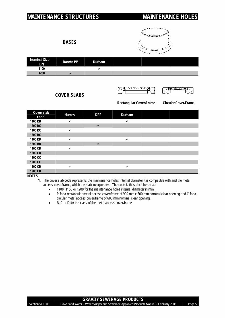
BASES
Nominal SizeDN Darwin PP Durham
1100 a1200 a
COVER SLABS Rectangular Cover/Frame Circular Cover/Frame
Cover slabcode1 Humes DPP Durham
1100 RB a a1200 RC a1100 RC a1200 RC1100 RD a a1200 RD a1100 CB a1200 CB1100 CC1200 CC1100 CD a a1200 CD
NOTES1. The cover slab code represents the maintenance holes internal diameter it is compatible with and the metal
access cover/frame, which the slab incorporates. The code is thus deciphered as:• 1100, 1150 or 1200 for the maintenance holes internal diameter in mm• R for a rectangular metal access cover/frame of 900 mm x 600 mm nominal clear opening and C for a
circular metal access cover/frame of 600 mm nominal clear opening.• B, C or D for the class of the metal access cover/frame

MAINTENANCE STRUCTURES MAINTENANCE SHAFTS
GRAVITY SEWERAGE PRODUCTSSection SGO 01 Power and Water – Water Supply and Sewerage Approved Products Manual – February 2006 Page 6
MAINTENANCE SHAFTS
IN-LINE CHAMBERSSO(RRJ) - SO(RRJ) – SO(SCJ)
Nominal SizeDN Aymroo SMS Wormall
(Poo-Pit)150 x 150 a a *225 x 225 a *
* Interim approval for use only in Alice Springs, Kings Canyon and Yulara
ELBOW CHAMBERSSO(RRJ) - SO(RRJ) – SO(SCJ)
Nominal SizeDN x bend angle Aymroo Wormall
(Poo-Pit)150 x 15° LEFT a *150 x 15° RIGHT a *225 x 15° LEFT a *225 x 15° RIGHT a *150 x 22.5° LEFT a *150 x 22.5° RIGHT a *225 x 22.5° LEFT a *225 x 22.5° RIGHT a *150 x 30° LEFT a *150 x 30° RIGHT a *225 x 30° LEFT a *225 x 30° RIGHT a *150 x 45° LEFT a *150 x 45° RIGHT a *225 x 45° LEFT a *225 x 45° RIGHT a *150 x 60° LEFT a *150 x 60° RIGHT a *225 x 60° LEFT a *225 x 60° RIGHT a *150 x 90° a *225 x 90° a *
* Interim approval for use only in Alice Springs, Kings Canyon and Yulara
TERMINAL CHAMBERSSO(RRJ) - SO(SCJ)
Nominal SizeDN Aymroo Wormall
(Poo-Pit)150 a *225 a *
* Interim approval for use only in Alice Springs, Kings Canyon and Yulara

MAINTENANCE STRUCTURES MAINTENANCE SHAFTS
GRAVITY SEWERAGE PRODUCTSSection SGO 01 Power and Water – Water Supply and Sewerage Approved Products Manual – February 2006 Page 7
SHORT RADIUS RISER BENDSSP-SO SCJ
Nominal SizeDN x bend angle Aymroo
225 x 1° a225 x 2° a225 x 3° a225 x 4° a225 x 5° a
RISER JUNCTIONS
Nominal Size Aymroo225 x 150 SO-SO-SO RRJ a225 X 150 SP-SO-SO RRJ a225 x 150 SO-SO-SO SCJ a225 x 150 SP-SO-SO SCJ a
RISER BAYONET CAP
Nominal Size Aymroo SMS(BT Bautechnik)
SMS(Iplex)
225 a a a
CIRCULAR WATERTIGHT SOLID TOPCOVER DN 375
Class Cooke DurhamB ID a I
I = Interim

MAINTENANCE STRUCTURES MAINTENANCE SHAFTS
GRAVITY SEWERAGE PRODUCTSSection SGO 01 Power and Water – Water Supply and Sewerage Approved Products Manual – February 2006 Page 8
COVER SLABS
DPP DurhamI a
I = Interim

MAINTENANCE STRUCTURES INSPECTION OPENINGS
GRAVITY SEWERAGE PRODUCTSSection SGO 01 Power and Water – Water Supply and Sewerage Approved Products Manual – February 2006 Page 9
INSPECTION OPENINGS
LIGHT DUTY I.O.(COVER AND FRAME)
Concrete LD I.O.
Type HumesLD IO C aLD IO R
TERMINOLOGY:- C is for circular I.O., R is for rectangular I.O.
LIGHT DUTY I.O. WITHIN CONCRETESURROUND
LD I.O. within concrete surround
Type Humes DPP DurhamLD IO C & Surround a a aLD IO R & Surround
TERMINOLOGY:- C is for circular I.O., R is for rectangular I.O.
HEAVY DUTY I.O.(COVER AND FRAME)
Cast Iron HD I.O.
Gatic-Milnes Cooke/Trigg DurhamHD IO a a a
HEAVY DUTY I.O. WITHIN CONCRETESURROUND
HD I.O. within concrete surroundNominal Size Humes Cooke DPP DurhamHD IO & Surround a a a a

MAINTENANCE STRUCTURES MH ANCILLARIES
GRAVITY SEWERAGE PRODUCTSSection SGO 01 Power and Water – Water Supply and Sewerage Approved Products Manual – February 2006 Page 10
MH ANCILLARIES
LADDERS
Material Miyama1
GRP aPolyethyleneStainless steelGalvanised steel
NOTES1. Miyama provide polypropylene/GRP ladder fastening brackets for rectangular maintenance holes and GRP
ladder fastening brackets for circular maintenance holes. Nuts and bolts with the brackets, excluding thestainless steel wall fastenings, are made of polyamide resin nuts and bolts.
PLASTIC ENCAPSULATED STEP IRONS
Nominal StepWidth (mm) Miyama
400 a

MAINTENANCE STRUCTURES CONCRETE MH JOINTING & REPAIR
GRAVITY SEWERAGE PRODUCTSSection SGO 01 Power and Water – Water Supply and Sewerage Approved Products Manual – February 2006 Page 11
MH JOINTING & REPAIR
EPOXIES
Size Vivacity(Kit) (Megapoxy P1)4L a
20L a
NOTES1. Shelf life limited to 2 years