the international conference on earthquake engineering...
TRANSCRIPT

Naveed AnwarICEES 2011
25 - 26 April 2011
NUST, Islamabad Pakistan
The International Conference on Earthquake Engineering and Seismology

CE 72.32 - Design of Tall Buildings - January 2011, Dr. Naveed Anwar 2
• The why, the how and the what of Performance Based Design and Review of Tall Buildings
• Application of recent research and development to real world problems within the associated cost and time constraints
• Demonstrated outcome for the client/owners/public

CE 72.32 - Design of Tall Buildings - January 2011, Dr. Naveed Anwar
• Naveed Anwar
Faculty, SEC, AIT
CEO, AIT Consulting
• Thaung Htut Aung
Projects Coordinator, AIT Consulting
• Rojit Shahi
Project Specialist, AIT Consulting
• Amelia Kusuma
Project Specialist, AIT Consulting
• Deepak Rayamajhi
External Consultant, AIT Consulting
• Pennung Warnitchai
Associate Prof., SEC, AIT
• Keerati Tunthasuwattana
Manager, ACECOMS, AIT
3

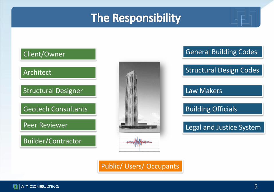
• Why do we need to carryout Performance Based Design/ Evaluation when we have the building and design codes
5
Building Officials
Structural Designer
Architect Structural Design Codes
General Building Codes
Legal and Justice System
Public/ Users/ Occupants
Client/Owner
Law Makers
Builder/Contractor
Peer Reviewer
Geotech Consultants

CE 72.32 - Design of Tall Buildings - January 2011, Dr. Naveed Anwar 6
• Traditional codes govern design of general, normal buildings– Over 95% buildings are covered, which are less than about 50 m
• Not specifically developed for tall buildings > 50 m tall
• Prescriptive in nature, no explicit check on outcome
• Permit a limited number of structural systems
• Do not include framing systems appropriate for high rise
• Based on elastic methods of analysis
• Enforce uniform detailing rules on all members
• Enforce unreasonable demand distribution rules
• Do not take advantage of recent computing tools

CE 72.32 - Design of Tall Buildings - January 2011, Dr. Naveed Anwar 7
• Applied Technology Council (ATC-72)
• Pacific Earthquake Engineering Research Center (PEER)
• Building Seismic Safety Council Research Center (BSSCR)
• Federal Emergency Management Agency (FEMA 356)
• Basic ASCE Documents (ASCE 7, ASCE 3, ASCE 4)
• Structural Engineering Association of California (Blue Book and SEAOC PBD Framework)
• Guidelines from National Earthquake Hazard Reduction Program (NEHRP)
• Los Angeles Tall Buildings Structural Design Council (LATBSDC)
• Council on Tall Buildings and Urban Habitat (CTBUH)

• What is needed and needs to be done to carry out an effective Performance Based Design and Evaluation

CE 72.32 - Design of Tall Buildings - January 2011, Dr. Naveed Anwar 9
• To enhance the structural performance– Improved serviceability, safety and reliability
– Explicit check on various performance indicators
• To improve cost effectiveness – Achieve efficient use of materials, resources and time
– Direct reduction cost through reduction of structural material quantities
• Objectives to be achieved through– Better structural system selection and its proportions
– Use of advanced design methodologies and tools

CE 72.32 - Design of Tall Buildings - January 2011, Dr. Naveed Anwar
• Enhancement of Performance– Dynamic response
parameters
– Lateral load response
– Vertical load response
– Demand and capacity ratios
– Response irregularity, discontinuity
– Explicit Performance Evaluation at Service, DBE and MCE
• Cost Effectiveness– Capacity utilization ratio
– Reinforcement ratios
– Reinforcement volume ratios
– Concrete strength and quantity
– Rebar quantity
– Constructability, time and accommodation of other constraints
10

11
Level of Earthquake Seismic Performance Objective
Frequent/Service: 50% probability of exceedance in 30 years (43-year return period)
Serviceability: Structure to remain essentially elastic with minor damage to structural and non-structural elements
Design Basis Earthquake (DBE): 10% probability of exceedance in 50 years (475-year return period)
Code Level: Moderate structural damage; extensive repairs may be required
Maximum Considered Earthquake (MCE): 2% probability of exceedance in 50 years (2475-year return period)
Collapse Prevention: Extensive structural damage; repairs are required and may not be economically feasible

CE 72.32 - Design of Tall Buildings - January 2011, Dr. Naveed Anwar 12
• Seven site specific ground motions records are used.
• Determined by qualified geotechnical and geological consultant, for the site located near by building.
• For the evaluations, “Average of 7 pairs of ground motions” approach is used to determine the overall response and vulnerability of the building.

13

14

15
Service Level
MCE Level

CE 72.32 - Design of Tall Buildings - January 2011, Dr. Naveed Anwar 16
Element Action Type Classification ExpectedBehavior
RC column Axial-flexureShear
DuctileBrittle
LinearLinear
RC shear wall FlexureShear
DuctileBrittle
NonlinearLinear
RC coupling beams (Deep beam, ln/d<4.0)
Shear Ductile Nonlinear
RC coupling beams (slender beam, ln/d≥4.0)
FlexureShear
DuctileBrittle
NonlinearLinear

CE 72.32 - Design of Tall Buildings - January 2011, Dr. Naveed Anwar 17
Item Limit
Story Drift 0.5 percent
Coupling Beams Shear strength to remain essentially elastic
Core Wall Flexure Remain essentially elastic
Core Wall Shear Remain essentially elastic
Columns Remain essentially elastic
BRB Remain elastic (no yielding permitted)
• Essentially elastic behavior is defined as no more than 20% of the elements with ductile actions having a D/C between 1.0 and 1.5. No elements will be allowed to have a D/C >1.5
• Brittle actions are limited to D/C of 1.0
CE 72.32 - Design of Tall Buildings - January 2011, Dr. Naveed Anwar 18
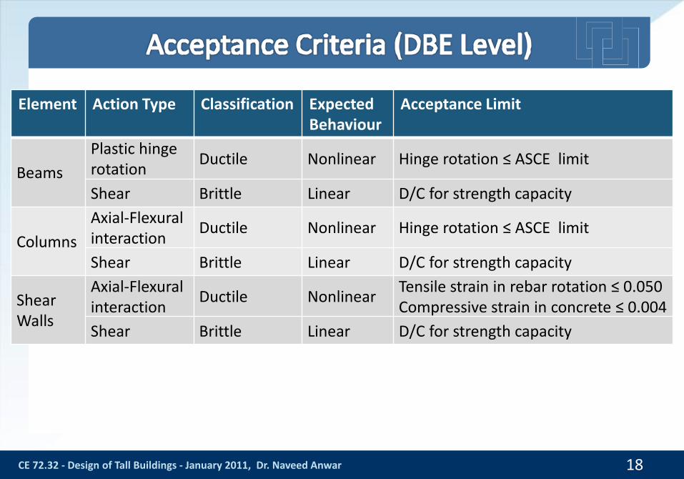
Element Action Type Classification ExpectedBehaviour
Acceptance Limit
Beams
Plastic hinge rotation
Ductile Nonlinear Hinge rotation ≤ ASCE limit
Shear Brittle Linear D/C for strength capacity
Columns
Axial-Flexural interaction
Ductile Nonlinear Hinge rotation ≤ ASCE limit
Shear Brittle Linear D/C for strength capacity
Shear Walls
Axial-Flexural interaction
Ductile NonlinearTensile strain in rebar rotation ≤ 0.050Compressive strain in concrete ≤ 0.004
Shear Brittle Linear D/C for strength capacity
CE 72.32 - Design of Tall Buildings - January 2011, Dr. Naveed Anwar 19
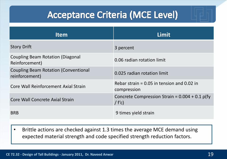
Item Limit
Story Drift 3 percent
Coupling Beam Rotation (Diagonal Reinforcement)
0.06 radian rotation limit
Coupling Beam Rotation (Conventional reinforcement)
0.025 radian rotation limit
Core Wall Reinforcement Axial StrainRebar strain = 0.05 in tension and 0.02 in compression
Core Wall Concrete Axial StrainConcrete Compression Strain = 0.004 + 0.1 ρ(fy / f’c)
BRB 9 times yield strain
• Brittle actions are checked against 1.3 times the average MCE demand using expected material strength and code specified strength reduction factors.

• How to carry out an effective Performance Based Design and Evaluation so that it can provide useful outcome
21
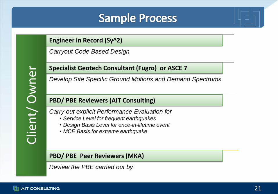
Clie
nt/
Ow
ner
Carryout Code Based Design
Develop Site Specific Ground Motions and Demand Spectrums
Carry out explicit Performance Evaluation for • Service Level for frequent earthquakes
• Design Basis Level for once-in-lifetime event
• MCE Basis for extreme earthquake
Review the PBE carried out by
Engineer in Record (Sy^2)
Specialist Geotech Consultant (Fugro) or ASCE 7
PBD/ PBE Reviewers (AIT Consulting)
PBD/ PBE Peer Reviewers (MKA)

CE 72.32 - Design of Tall Buildings - January 2011, Dr. Naveed Anwar 22
Design/ Evaluation Stage Analysis Type Software Used
Code based design and preliminary evaluation
Response spectrum analysis ETABS V9.5SAP 2000 V 14.2
Serviceability check Response spectrum analysis ETABS V9.5SAP 2000 V 14.2
Collapse prevention check Nonlinear time history analysis Perform3D V4.0.4SAP 2000 V 14.2
CE 72.32 - Design of Tall Buildings - January 2011, Dr. Naveed Anwar 23
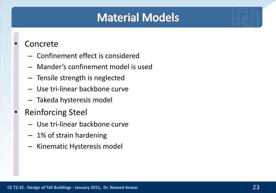
• Concrete– Confinement effect is considered
– Mander’s confinement model is used
– Tensile strength is neglected
– Use tri-linear backbone curve
– Takeda hysteresis model
• Reinforcing Steel– Use tri-linear backbone curve
– 1% of strain hardening
– Kinematic Hysteresis model

CE 72.32 - Design of Tall Buildings - January 2011, Dr. Naveed Anwar
• Fiber modeling– Two parallel fiber sections are
used
– Shear behavior is modeled as elastic
• Nonlinear Shell Element– 7 layer NL shell with explicit
cover, mid portion, vertical and horizontal bars
24

CE 72.32 - Design of Tall Buildings - January 2011, Dr. Naveed Anwar
• Use rigid diaphragm
• Equivalent slab outrigger beams connected the core and columns
• Moment curvature hinges are used
25


CE 72.32 - Design of Tall Buildings - January 2011, Dr. Naveed Anwar
• Located in Philippines
• 50-story building with 3½ -story below grade parking
• Total height of 166.8 m above ground level
• 34.5 x 26 meters plan dimension
27
Designer : Sy^2 + Associates Inc
Performance reviewer : AIT Consulting
Peer reviewer for Performance Based Design: Magnusson Klemencic Associates

28Tower 1
BRBs (43rd – 47th floor)
BRBs (19th – 23rd floor)
Principal Major Direction
Principal Minor Direction

CE 72.32 - Design of Tall Buildings - January 2011, Dr. Naveed Anwar 29
BRB in Plan
Principal Major Direction
Principal Minor Direction
CE 72.32 - Design of Tall Buildings - January 2011, Dr. Naveed Anwar
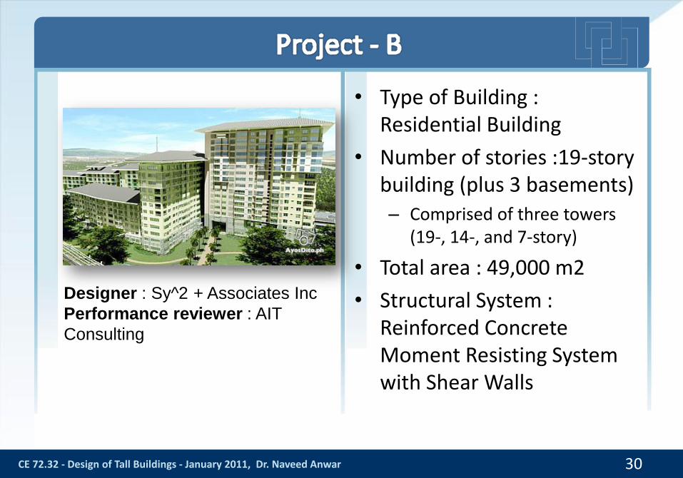
• Type of Building : Residential Building
• Number of stories :19-story building (plus 3 basements)– Comprised of three towers
(19-, 14-, and 7-story)
• Total area : 49,000 m2
• Structural System : Reinforced Concrete Moment Resisting System with Shear Walls
30
Designer : Sy^2 + Associates Inc
Performance reviewer : AIT
Consulting

CE 72.32 - Design of Tall Buildings - January 2011, Dr. Naveed Anwar
• Part 1 is the tallest part and has irregularity in plan, with 19 floors.
• Part 2 is the second tallest part of the building with few irregularities in plan and 14 floors.
• Part 3 is the lowest part and generally regular in geometry and stiffness with 7 floors.
31
Layout Plan of Each Part of the
Building
Part 1
Part 2
Part 3

32
Part 1 Part 2 Part 3

CE 72.32 - Design of Tall Buildings - January 2011, Dr. Naveed Anwar 33
• Reinforced concrete residential building
• 70-Story building plus 5 basements
• Total height of 242m height
• Approximate floor area of 100,000 m2
• Structural system: Moment resisting frames with shear walls
• Mega-truss wall (MTW) panels to control the lateral deformation
• Designer : R.S Caparros Associates
• Sy^2 + Associates Inc.
• Performance Reviewer : AIT Consulting

34
Typical tower framing plan Sectional elevation of MTW panel
`

CE 72.32 - Design of Tall Buildings - January 2011, Dr. Naveed Anwar 35
• Modeled using ETABS for DBE Response Spectrum
• Member stiffness properties are adjusted in accordance with effective stiffness values given in Table 6-5 of FEMA 356 provisions
Typical Floor Plan Full 3D Finite Element Model

CE 72.32 - Design of Tall Buildings - January 2011, Dr. Naveed Anwar 36
• 3D nonlinear model using PERFORM-3D
• Seven pairs of site ground motions used
• Shear wall modeling
• Inelastic wall element is used.
• Fiber modelling technique is used to model the flexural behaviour.
• Out-of-plane bending and shear is kept elastic.
• Out of plane stiffness of the wall is reduced to 1/4 value to account the effect of concrete cracking. Full 3D Finite Element Model

CE 72.32 - Design of Tall Buildings - January 2011, Dr. Naveed Anwar 37
• Floor area: 56,000 m2
• Type of building: Residential Building
• Structural system: Reinforced concrete moment resisting building with shear walls

CE 72.32 - Design of Tall Buildings - January 2011, Dr. Naveed Anwar 38
• Floor area: 85,000 m2
• Type of building: Residential Building
• Structural system: Reinforced concrete moment resisting building with shear walls
CE 72.32 - Design of Tall Buildings - January 2011, Dr. Naveed Anwar 39
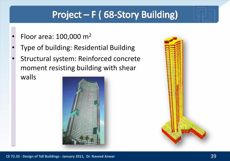
• Floor area: 100,000 m2
• Type of building: Residential Building
• Structural system: Reinforced concrete moment resisting building with shear walls


Mode Natural Period (s) Mode Shape
1 5.75 Translation in minor dir.
2 4.86 Translation in major dir.
3 3.77 Torsion
41
Minor
Major
Mode 1 Mode 2 Mode 3

Tran
slat
ion
in M
ino
r d
ire
ctio
nTr
ansl
atio
nin
Maj
or
dir
ect
ion
Tors
ion
al
42
• T1=5.32 sec
• 60% in Minor
direction
• T6=1.28 sec
• 18% in Minor
direction
• T9=5.32 sec
• 6.5% in Minor
direction
• T2=4.96 sec
• 66% in Major
direction
• T7=0.81 sec
• 5.2% in Major
direction
• T4=1.56 sec
• 15% in Major
direction
T3=4.12 sec T8=0.65secT5=1.30 sec

43
• Design base shear is larger than minimum limit of 3% set by LATBSDC-2008
• Nonlinear dynamic base shear is approximately 2 times higher than design base shear
Load CasesBase Shear
(KN) % of Seismic Weight
DBE level (In major dir.) 21,012 3.56
DBE level (In minor dir.) 22,691 3.84
MCE level (In major dir.) 47,892 7.76
MCE level (In minor dir.) 46,462 7.53

CE 72.32 - Design of Tall Buildings - January 2011, Dr. Naveed Anwar 44
Weak Direction
(Y)
Strong Direction
(X)

CE 72.32 - Design of Tall Buildings - January 2011, Dr. Naveed Anwar 45
Weak Direction
(Y)
Strong Direction
(X)
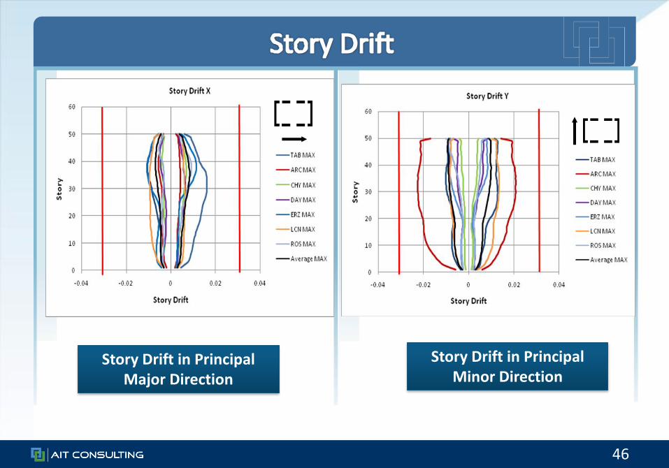
46
Story Drift in Principal Major Direction
Story Drift in Principal Minor Direction

47
Story Shear in Principal Major Direction
Story Shear in Principal Minor Direction

48
Story Moment about Principal Minor Axis
Story Moment about Principal Major Axis

49
Wall Compressive Axial Strain Wall Tensile Axial Strain
-10
0
10
20
30
40
50
60
-0.005 -0.004 -0.003 -0.002 -0.001 0
Sto
ry
Axial Strain
Wall Compressive Axial Strain at Location 1-2Compressive Strain=2 times MCE strain
TAB MIN
ARC MIN
CHY MIN
DAY MIN
ERZ MIN
LCN MIN
ROS MIN
Average MIN-10
0
10
20
30
40
50
60
0 0.001 0.002 0.003 0.004 0.005 0.006 0.007S
to
ry
Axial Strain
Wall Tensile Axial Strain at Location 1-2Compressive Strain=2 times MCE strain
TAB MAX
ARC MAX
CHY MAX
DAY MAX
ERZ MAX
LCN MAX
ROS MAX
Average MAX

CE 72.32 - Design of Tall Buildings - January 2011, Dr. Naveed Anwar 50

51
0%
10%
20%
30%
40%
50%
60%
70%
80%
90%
100%
PART 1 PART 2 PART 3
Summary of Beams Flexural Deformation
Beyond CP
Between LS and CP
Between IO and LS
Before IO
0%
10%
20%
30%
40%
50%
60%
70%
80%
90%
100%
PART 1 PART 2 PART 3
Girder Shear Design Check Summary
Under demand
Just enough
Good

52
0.00%
10.00%
20.00%
30.00%
40.00%
50.00%
60.00%
70.00%
80.00%
90.00%
100.00%
PART 1 PART 2 PART 3
Summary of Column Flexural Deformation
Beyond CP
Between LS and CP
Between IO and LS
Before IO
0%
10%
20%
30%
40%
50%
60%
70%
80%
90%
100%
PART 1 PART 2 PART 3
Column Shear Design Check Summary
Under demand
Just enough
Good

CE 72.32 - Design of Tall Buildings - January 2011, Dr. Naveed Anwar 53
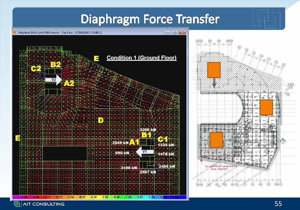
Percentage of Total Base Shear Distributed to Shear Walls and MomentResisting Frame from Equivalent Static Analysis
0%
10%
20%
30%
40%
50%
60%
70%
80%
90%
100%
% (X-dir) % (Y-dir) % (X-dir) % (Y-dir) % (X-dir) % (Y-dir)
Part 1 Part 2 Part 3
93 9282 79
30
86
7 818 21
70
14
Frame
Shear Wall

CE 72.32 - Design of Tall Buildings - January 2011, Dr. Naveed Anwar 54
Part Level Maximum Displacement Check
12
1489.3 mm82.6 mm
(89.3 + 82.6) mm = 171.9 mm < 250 mm
23
762.1 mm59.8 mm
(62.1 + 59.8) mm = 121.9 mm < 250 mm
Seismic gap size : 250 mm
55
56
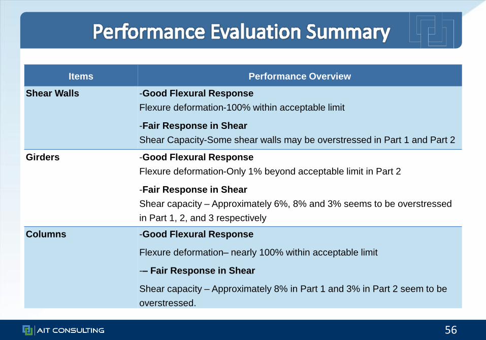
Items Performance Overview
Shear Walls -Good Flexural Response
Flexure deformation-100% within acceptable limit
-Fair Response in Shear
Shear Capacity-Some shear walls may be overstressed in Part 1 and Part 2
Girders -Good Flexural Response
Flexure deformation-Only 1% beyond acceptable limit in Part 2
-Fair Response in Shear
Shear capacity – Approximately 6%, 8% and 3% seems to be overstressed
in Part 1, 2, and 3 respectively
Columns -Good Flexural Response
Flexure deformation– nearly 100% within acceptable limit
-– Fair Response in Shear
Shear capacity – Approximately 8% in Part 1 and 3% in Part 2 seem to be
overstressed.

57
58

59

CE 72.32 - Design of Tall Buildings - January 2011, Dr. Naveed Anwar 61
• This is an attempt to explicitly check that the Building – Is serviceable under Frequent Earthquakes
– Has limited damage during Design Basis Earthquake
– Does not collapse in Maximum Credible earthquake
• This is done by– Avoiding the uncertainties that are inherent in traditional code based.
– Avoiding the uncertainties in the use of global force reduction/over strength factor R
– Considering the higher mode effects
– Considering the nonlinearities and dynamics in appropriate manner
• Use the state of the art knowledge and techniques for tall building design