the inductrack: a home-grown maglev system for our nation · the inductrack: a home-grown maglev...
TRANSCRIPT
The Inductrack: A Home-Grown Maglev
System for our Nation
Lockheed Martin Palo Alto Colloquium
Presented by: Richard F. Post,
Lawrence Livermore National Laboratory
15 Apr 2004
Lock./01

There are many reasons why magnetically levitated
trains could be preferred over conventional trains
• Inter-city transportation: Much higher speeds than are possible
with steel-wheeled trains, lower noise, greater passenger
comfort, increased safety against mechanical failures, reduced
maintenance.
• Relative to aircraft: Higher energy efficiency, safer, less
weather-dependent, and would permit in-city departure and
arrival.
• Urban transit systems: Lower noise, much lower maintenance,
greater rider comfort, can climb steeper grades, potentially
higher energy efficiency than buses or rubber-tired urban trains.
Lock./02

Two different types of Maglev trains have been built and
demonstrated at full scale at speeds up to 500 km/hr
• Magnetic attraction - EMS (Electro-Magnetic Suspension) systems,
using servo-controlled electromagnets on the train car, attracted
upward to a iron-plate rail.
• Magnetic repulsion -EDS (Electro-Dynamic Suspension) systems,
using cryogenically cooled superconducting magnets on the moving
car, repelled by currents induced in coils embedded in “tracks” on each
side of the train.
• Example EMS system: The German Trans-Rapid TR08 demonstration
train and 30 kilometer test track, with operating speeds up to 450
km/hr.
• Example EDS system: The Japanese Yamanashi demonstration train,
with speeds of 500 km/hr on a 18 kilometer test track.
Lock./03

The German Trans-Rapid maglev train is an EMS
system using electromagnets attracted to an iron “rail”
Gap: 1 cm ± 1 mm
Iron-plate "rail"
Iron magnet yokeTo control amplifier To control amplifier
(on train car)
Lock/04
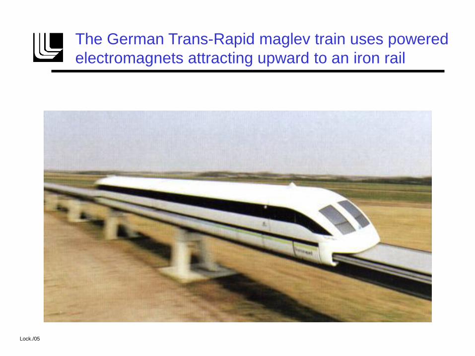
The German Trans-Rapid maglev train uses powered
electromagnets attracting upward to an iron rail
Lock./05

The Japanese Yamanashi demonstration maglev
train uses superconducting magnets on its sides
Lock./06

At speed superconducting magnet coils on the Japanese
train induce currents in coils in the “tracks” on each side
Lock./07
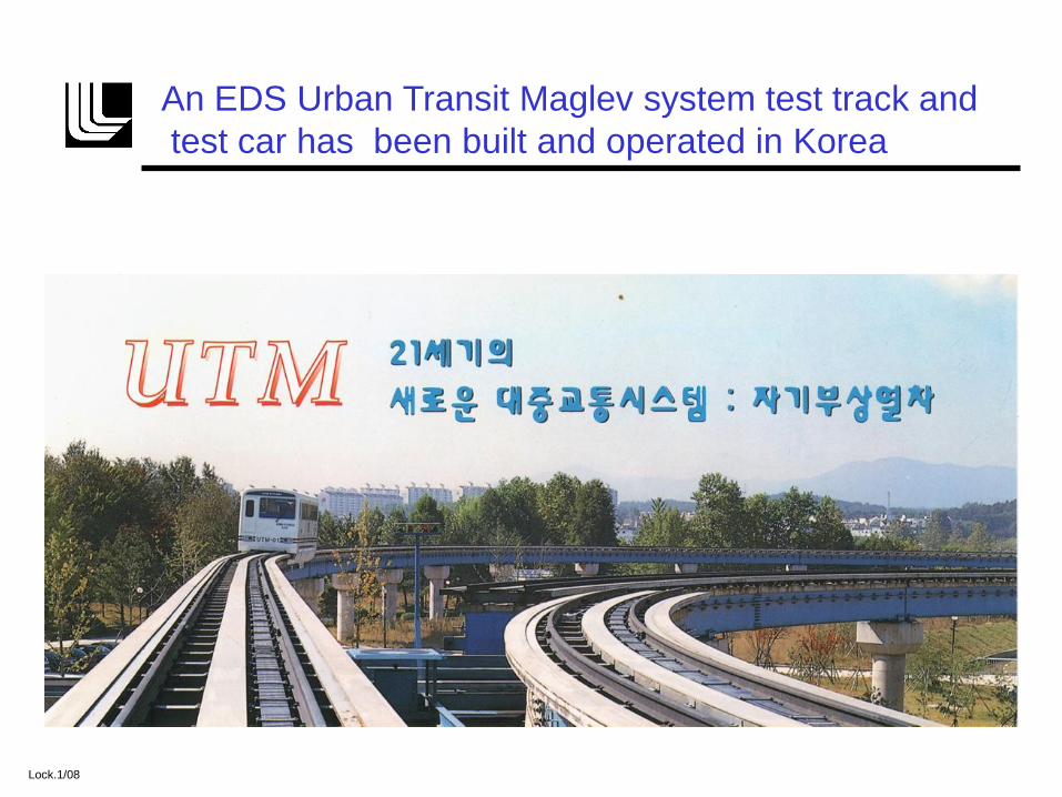
An EDS Urban Transit Maglev system test track and
test car has been built and operated in Korea
Lock.1/08

The proposed “Swiss-Metro” would link major Swiss
cities by maglev trains running in evacuated tunnels.
Proposed in 1974, and under study since 1989, the Swiss-Metro system would carry
200 passengers in train cars running every 6 minutes. The trains would operate in
tunnels evacuated to 1/10 atmosphere (atmos. pressure at Concorde flying altitude).
Contactless energy
transfer system
Linear electric motor
and guidance system
Magnetic levitation
inductor
Emergency pavementEmergency guidance
And braking system
Lock./09

The LLNL “Inductrack” maglev system developed as a
spin-off from the Lab’s flywheel energy storage program
• It is an EDS system, but uses only permanent magnets and does not
require cryogenically cooled superconducting coils
• It is a passive system that requires no control circuits to maintain stable
levitation
• Levitation off of the auxiliary wheels occurs as soon as a low “transition
speed” is reached.
• The Inductrack system is”fail safe” in the event of a power failure; the
train car would simply slow down and settle down on its auxiliary
wheels at a low speed.
• The simplicity of the Inductrack should make it substantially less
expensive than the present EDS or EMS maglev trains.
Lock./10
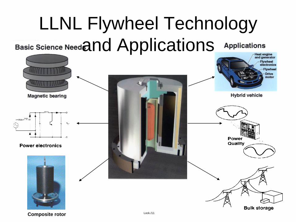
LLNL Flywheel Technology
and Applications
Integrated System
Composite rotor Lock./11

The Inductrack system optimizes levitation efficiency,
using permanent magnets and a passive “track.”
• Special arrays (Halbach arrays) of permanent
magnets are employed, mounted on “bogies”
underneath the car.
• The periodic magnetic fields from the magnet arrays
on the moving train car induce currents in a close-
packed array of shorted electrical coils in the “track”
to produce levitation (above a low “transition” speed).
Lock./12

In the 1980’s Klaus Halbach came up with better ways to
employ permanent magnets in focusing particle beams
• The Halbach array makes optimal use of permanent-magnet material by concentrating the field on the front face of the array, while nearly canceling the field on the back face of the array
• The magnetic field on the front face of the array varies sinusoidally with position parallel to the face of the array, and falls off exponentially with distance away from the front face.
• Only permanent-magnet material is employed in Halbach arrays; no “back iron”elements or iron poles are needed.
Lock./13

Klaus Halbach 1925-2000
Klaus Halbach, good friend
and kind mentor, died on 11 May 2000.
Lock./14
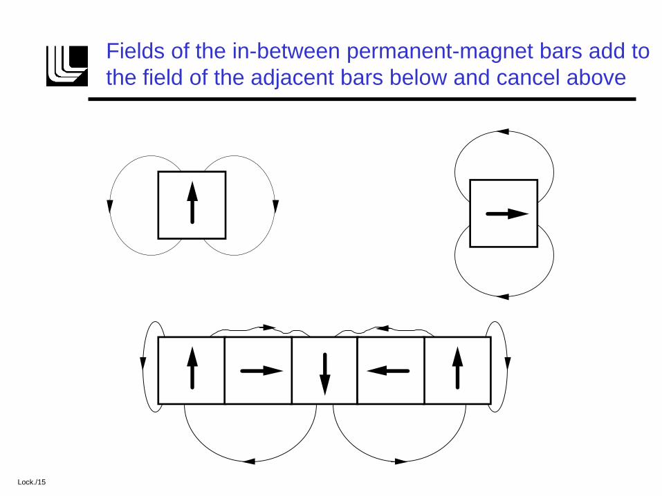
Fields of the in-between permanent-magnet bars add to
the field of the adjacent bars below and cancel above
Lock./15
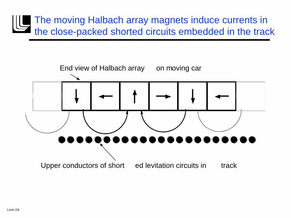
The moving Halbach array magnets induce currents in
the close-packed shorted circuits embedded in the track
End view of Halbach array on moving car
Upper conductors of short ed levitation circuits in track
Lock./16
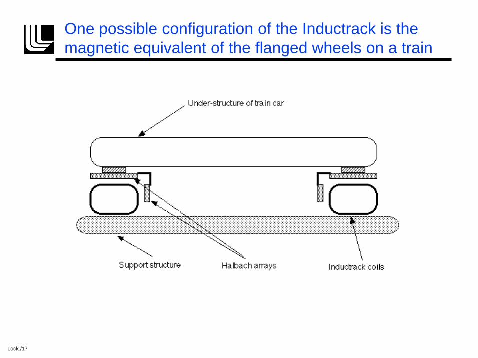
One possible configuration of the Inductrack is the
magnetic equivalent of the flanged wheels on a train
Lock./17

The levitating force becomes effective at very low
vehicle speeds and remains constant at high speeds
Lock./18
0 5 10 15 20 25 30
0.0
0.2
0.4
0.6
0.8
1.0
Fraction of Maximum Levitation Force vs Speed
Speed (km/hr)
Fra
cti
on
of
Ma
xim
um
Lif
t F
orc
e
Transition speed (1.2 km/hr)

The Lift-to-drag ratio of the Inductrack increases linearly
with speed, and can exceed 200 at maglev train speeds
Lock./19
0 100 200 300 400 500
0
50
100
150
200
250
300
350
400
450
Lift/Drag Ratio for Inductrack and for Conducting Plate
Speed (km/hr)
Lif
t/D
rag
Conducting plate
Inductrack (L = 0)
Inductrack ( K = 3.0 Newtons/Watt)
(Wav elength of Halbach array = 1.0 m.)
Jet airplane
Conv . rails @ 250 km/hr
(aero. not included)

Our Inductrack model car is launched by
pulses from a series of electronic circuits
Lock./20

The model Inductrack levitated and traveled down its
track in good agreement with the theoretical design
• Front-view photograph of the cart and the track coil
assembly. The cart is shown in flight approximately 3
centimeters above the track at approximately 10.5 m/s.
•
Lock./21

Ferrite “tiles” add inductive loading for our model
Inductrack, reducing the transition speed.
Coil
Ferrite "Tile"
Schematic Drawing of Inductrack Model Track
Wood
Lock./22

The Inductrack maglev concept may help NASA reduce
the cost of launching satellites
• NASA studies project that savings of 30 to 40 percent of the rocket fuel, permitting single-stage-to-orbit missions, should be possible with maglev acceleration and launching up a sloping track at Mach 0.8.
• Under NASA sponsorship, we designed, built, and operated a model Inductrack system to demonstrate the concept, including a pulsed high-acceleration electromagnetic drive system.
• Preliminary estimates indicate that a full-scale Inductrack system for magnetically launching large rockets should be technically feasible.
Lock./23

Carbon fiber cradle was designed using ANSYS
Locations of each 5-magnet Halbach array(same front and back)
Ribs needed to withstand the repulsive force caused by the magnets andinduced current
65-cm
Cradle weight = 3.5 kg
Magnet weight = 5.5 kg
The cradle is fabricated from high-modulus carbon-fiber
composite to maximize rigidity and minimize weight
Lock./24

The levitated cradle surrounds the “track” that is
composed of levitation coils and interleaved drive coils
Guide rails to preventmagnets from hittingtrack prior to levitation
One of 6 magnets(3 front, 3 back)that provide levitationand centering forces
Steel box beam
Drive &levitationcoils intrack
C-fibercradlewith ribsto supportmagnetic force
Fiberglass I-beam
Lock./25

The NASA model track is made up of modules that are
composed of 13 interleaved drive and levitation coils
Drive Coil #6 GA Magnet Wire
4
1
Coil A ssembly: 1 3 Drive and Levit at ion Coils
Lev it at ion Coil #1 0 GA Magnet Wire
Dimensions incm
Tolerance + / - 0.05
5
6 5
1 2 1 5
Support blocks that
attach coils to rail
Lock./26

An analytical theory exists which can be used to
optimize the design parameters of an Inductrack system
• Lift-to-Drag ratios can be specified by design over a
wide range of parameters
• The ratio of levitated weight to magnet weight can be
optimized for a given application
• Levitation forces approaching the theoretical
maximum can be achieved in practical designs
• Economic factors, such as track conductor costs, can
be analyzed and optimized
• Stability can be assured by the satisfaction of specific
criteria (e.g., geometry, damping factors, etc.)
Lock./27

The levitation and drag forces of the Inductrack can be
analyzed using circuit theory and Maxwell’s equations
Induced voltage :
V LdI
dtRI 0 cos(t)
Induced current (steady state):
I(t) = 0
L
1
1(R /L)2
sin(t) (R /L)cos(t)
Lock./28
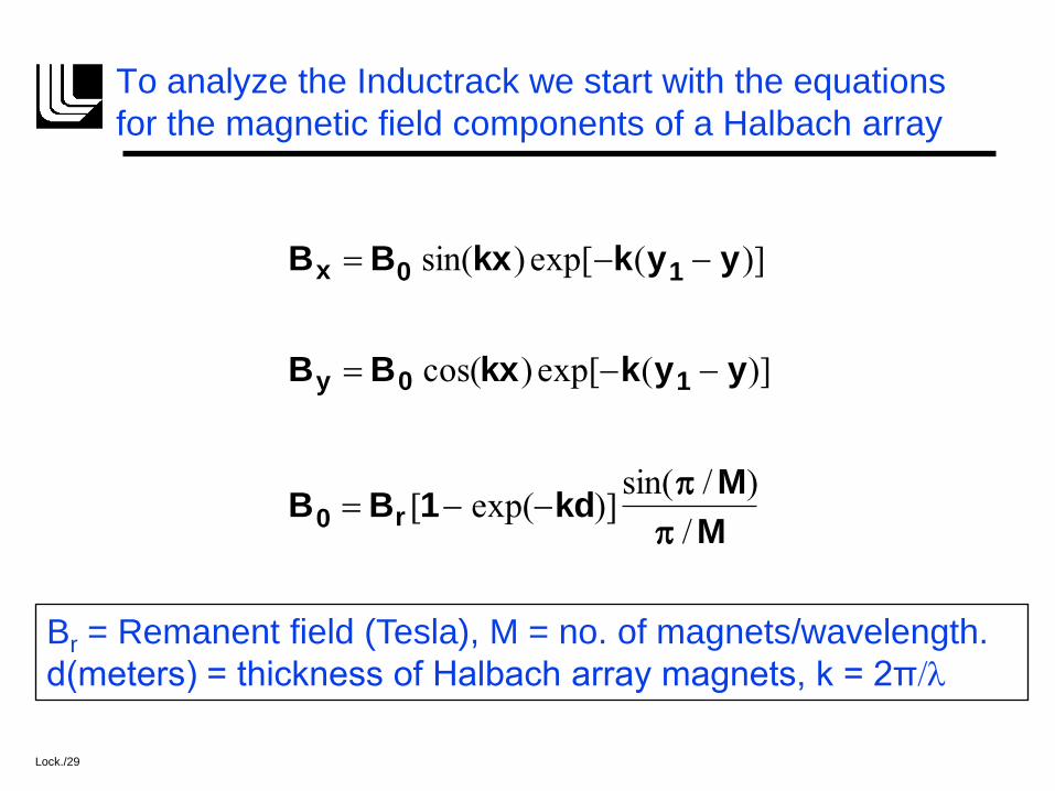
To analyze the Inductrack we start with the equations
for the magnetic field components of a Halbach array
Bx B0 sin(kx) exp[k(y1 y)]
By B0 cos(kx) exp[k(y1 y)]
B0 Br [1 exp(kd)]sin( / M)
/ M
Br = Remanent field (Tesla), M = no. of magnets/wavelength.
d(meters) = thickness of Halbach array magnets, k = 2π/l
Lock./29
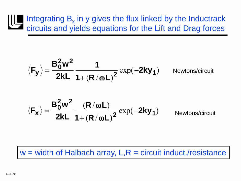
Integrating Bx in y gives the flux linked by the Inductrack
circuits and yields equations for the Lift and Drag forces
Fy B0
2w2
2kL
1
1 (R /L)2
exp(2ky1)
Fx B0
2w2
2kL
(R /L)
1 (R /L)2exp(2ky1)
w = width of Halbach array, L,R = circuit induct./resistance
Newtons/circuit
Newtons/circuit
Lock./30
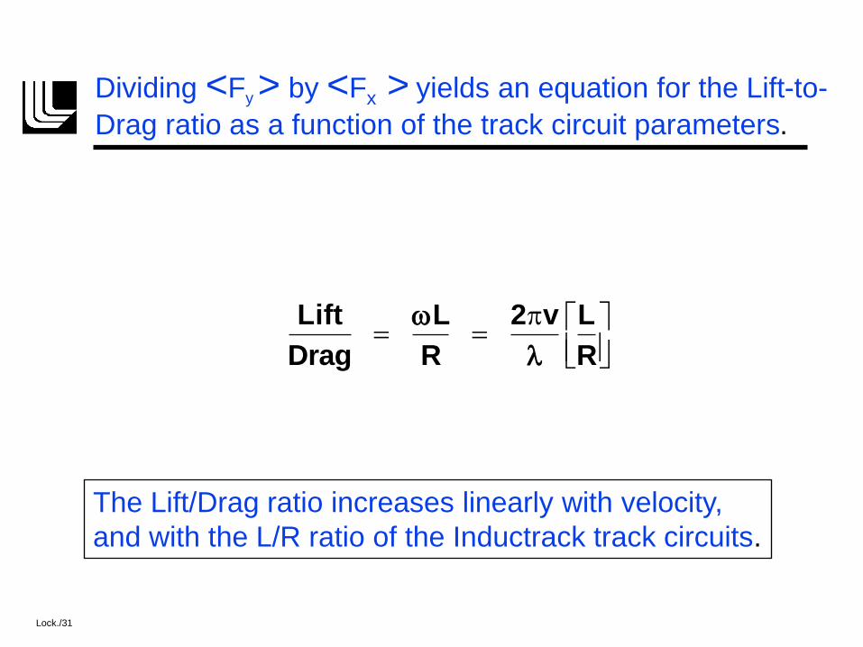
Dividing <Fy > by <Fx > yields an equation for the Lift-to-
Drag ratio as a function of the track circuit parameters.
Lift
Drag
L
R
2v
l
L
R
The Lift/Drag ratio increases linearly with velocity,
and with the L/R ratio of the Inductrack track circuits.
Lock./31

The levitation efficiency (Newtons/Watt) can be determined
directly from the equation for the Lift/Drag ratio
Since P Fx v, the equation
for the levitation efficiency is:
K Fy
P
2
l
L
R
Newtons/Watt
Typical K values: K=1.0 to 5.0, depending on track design
Lock./32
Design of the Levitation Track
The track design must fulfill the need for efficient and
cost-effective levitation coil circuits to take full
advantage of the Inductrack maglev configuration.
Two alternative track designs:
Litz-wire cables, encased in stainless steel tubes
Slotted, laminated, conductor sheets, bonded and
mechanically reinforced
Lock./33
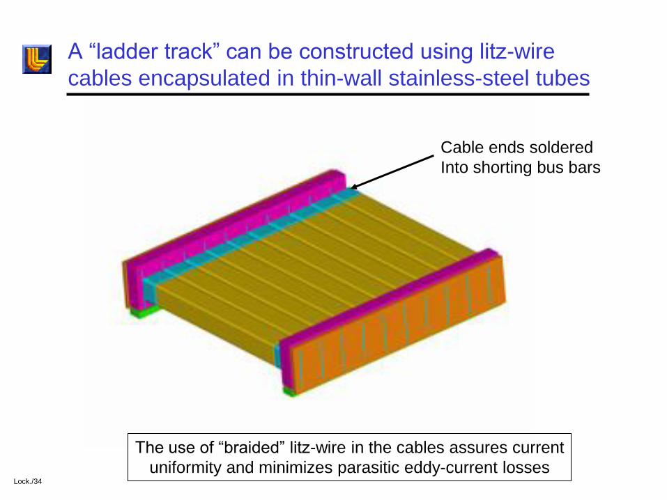
A “ladder track” can be constructed using litz-wire
cables encapsulated in thin-wall stainless-steel tubes
Cable ends soldered
Into shorting bus bars
The use of “braided” litz-wire in the cables assures current
uniformity and minimizes parasitic eddy-current lossesLock./34

The laminated “ladder track” is a high-efficiency, cost-
effective, alternative to the litz-wire ladder track
Laminated stack of slotted thin copper or anodized aluminum sheets
Lock./35
The feasibility of the laminated track as an alternative
to the litz-wire ladder track is under study at LLNL
A computer code based on the Inductrack theory has been
written to predict the lift and drag performance of the
laminated track.
An instrumented linear “test track” has been built
to provide scalable data for comparison with the code
and for use in the design of full-scale tracks.
The LLNL code has been benchmarked against test-rig
measurements for several Inductrack magnet
configurations.
Lock./36
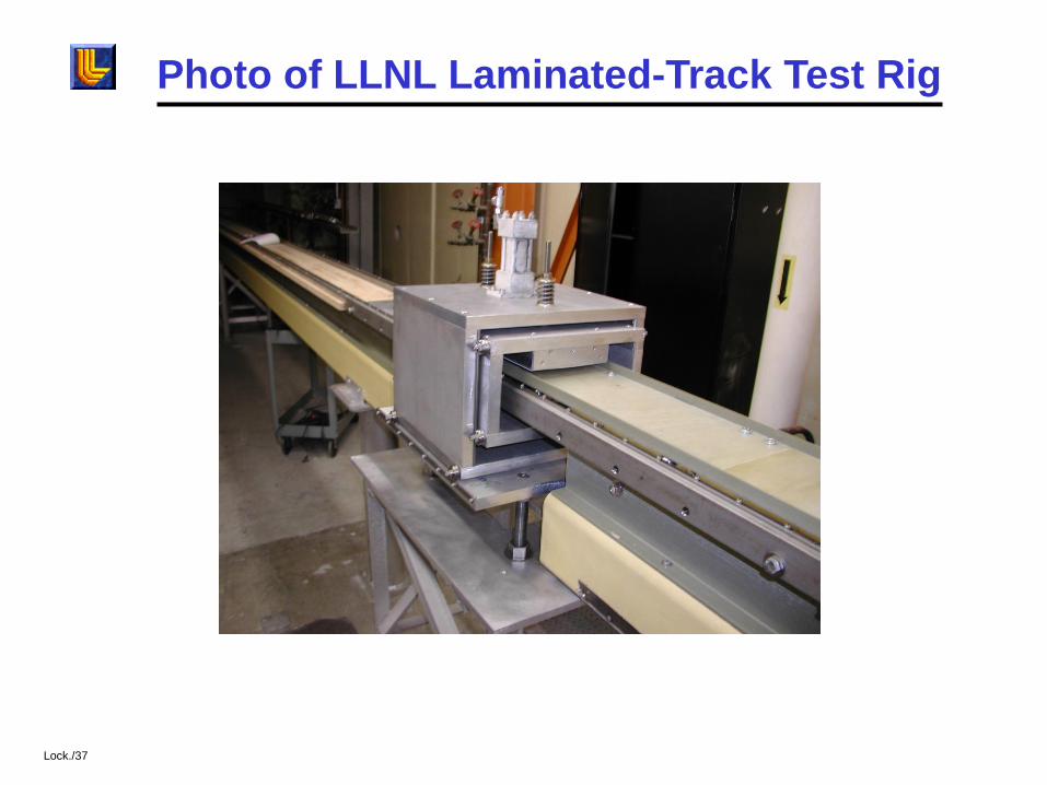
Photo of LLNL Laminated-Track Test Rig
Lock./37
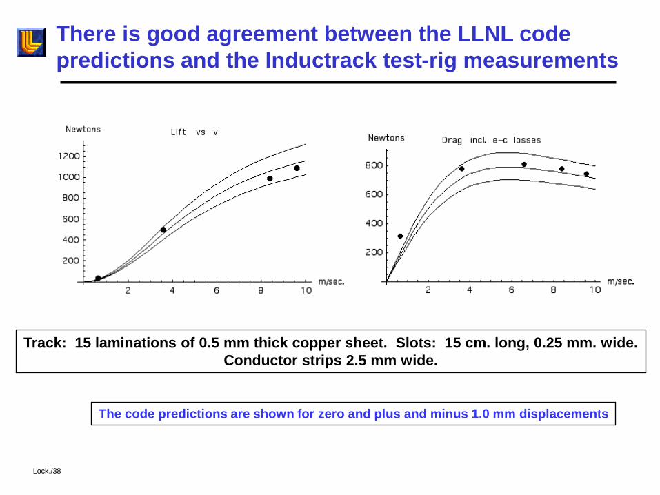
There is good agreement between the LLNL code
predictions and the Inductrack test-rig measurements
The code predictions are shown for zero and plus and minus 1.0 mm displacements
Track: 15 laminations of 0.5 mm thick copper sheet. Slots: 15 cm. long, 0.25 mm. wide.
Conductor strips 2.5 mm wide.
Lock./38
The Laboratory is a member of a team that is designing an
urban maglev system employing the Inductrack approach.
• The team (which also includes several engineering firms in the Pittsburgh, Penn. area), was organized by General Atomics (San Diego) and is funded by the Federal Transit Administration.
• The advantages of maglev in urban settings (relative to conventional urban rail systems) include: Lower noise, lower maintenance, higher efficiency, higher grade and tighter turn capabilities (allowing operation on elevated tracks that can accommodate to an urban environment without the need for underground-tunnel operation).
• Better to satisfy urban (moderate speed) applications we have developed the Inductrack II configuration, which greatly reduces electromagnetic drag forces at urban speeds (relative to Inductrack I, which is more suitable for high-speed applications).
Lock./39

The Inductrack II maglev employs dual Halbach arrays,
reducing drag losses and enhancing levitation forces
• A cantilevered ladder track is used, interacting with two facing Halbach
arrays, one above, and one below the track.
• The horizontal component of the magnetic fields from the upper and
lower Halbach arrays are additive, while the vertical field of the lower
array opposes that of the upper array.
• By adjusting the thickness or the width of the magnets of the lower
array relative to the upper array an optimum level of induced levitating
current can be achieved for a given levitated weight and magnet
weight.
• Either a litz-cable “flat track” or slotted, laminated, sheet conductors
with fiber composite reinforcement could be used to construct the
cantilevered track.
ILOck./40
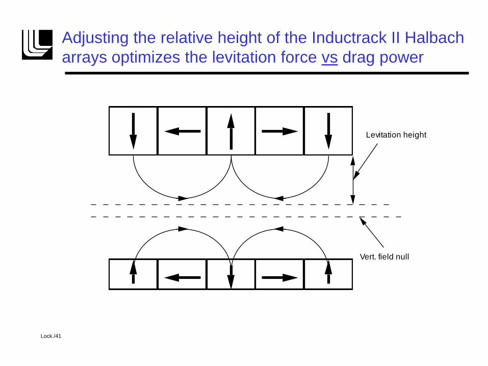
Adjusting the relative height of the Inductrack II Halbach
arrays optimizes the levitation force vs drag power
Vert. field null
Levitation height
Lock./41

Inductrack II Lift-to-Drag Ratios
• The L/D for Inductrack II systems is much higher than for Inductrack I
Inductrack I Inductrack II
Guideway parameters (both cases): 2.0 cm. laminated copper, p.f. = 0.9
Lock./42
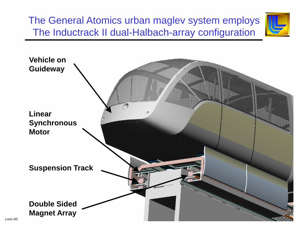
Vehicle on
Guideway
Linear
Synchronous
Motor
Suspension Track
Double Sided
Magnet Array
The General Atomics urban maglev system employs
The Inductrack II dual-Halbach-array configuration
Lock./43
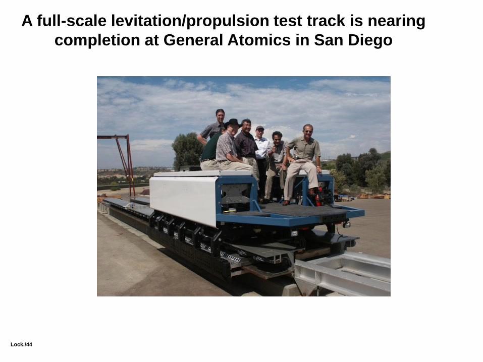
A full-scale levitation/propulsion test track is nearing
completion at General Atomics in San Diego
Lock./44

Summary
• Magnetic levitation (maglev) trains have been under development for many years in Germany and Japan for high-speed rail systems.
• Maglev would offer many advantages as compared to conventional rail systems or inter-city air travel.
• The cost and complexity of presently developed high-speed maglev trains has slowed their deployment.
• The Inductrack maglev system, employing simple arrays of permanent magnets, may offer an economic alternative to existing maglev systems.
• The simplicity of the Inductrack may make it attractive for use in a variety of applications, including urban maglev systems, people movers, and point-to-point shipment of high-value freight
• The Inductrack, employing Halbach arrays, is an example of a practical application of the results of fundamental studies in magnetics and particle-accelerator physics.
Lock./45