the hybrid hvdc breaker - abb group · pdf filethe transfer losses of the hybrid hvdc breaker...
TRANSCRIPT

ABB Grid Systems, Technical Paper Nov’2012
The Hybrid HVDC Breaker
An innovation breakthrough enabling reliable HVDC grids
Magnus Callavik, Anders Blomberg, Jürgen Häfner, Björn Jacobson
ABB Grid Systems
SUMMARY
Existing mechanical HVDC breakers are capable of interrupting HVDC currents within several tens of
milliseconds, but this is too slow to fulfill the requirements of a reliable HVDC grid. HVDC breakers
based on semiconductors can easily overcome the limitations of operating speed, but generate large
transfer losses, typically in the range of 30 percent of the losses of a voltage source converter station.
To overcome these obstacles, ABB has developed a hybrid HVDC breaker. The hybrid design has
negligible conduction losses, while preserving ultra-fast current interruption capability.
This paper will present a detailed description of the hybrid HVDC breaker, its design principles and
test results. The modular design of the hybrid breaker for HVDC applications is described.
Furthermore, the application of the hybrid breaker associated with the design of a HVDC switchyard
will be discussed.
KEYWORDS: HVDC grid; HVDC breaker - hybrid; Semiconductor breaker
_______________________________________________________________________________
1. INTRODUCTION
The advance of voltage source converter-based (VSC) high-voltage direct current (HVDC)
transmission systems makes it possible to build an HVDC grid with many terminals. Compared with
high-voltage alternating current (AC) grids, active power conduction losses are relatively low and
reactive power conduction losses are zero in an HVDC grid. This advantage makes an HVDC grid
more attractive [1]. However, the relatively low impedance in HVDC grids is a challenge when a short
circuit fault occurs, because the fault penetration is much faster and deeper. Consequently, fast and
reliable HVDC breakers are needed to isolate faults and avoid a collapse of the common HVDC grid
voltage. Furthermore, maintaining a reasonable level of HVDC voltage is a precondition for the
converter station to operate normally. In order to minimize disturbances in converter operation,
particularly the operation of stations not connected to the faulty line or cable, it is necessary to clear
the fault within a few milliseconds.
Recently, plans for large scale use of embedded VSC-HVDC transmission in point-to-point overhead
lines have been proposed, e.g. Germany, in the so-called Netzentwicklungsplan (NEP - Network
Development Plan). New generation from remote sites such as renewable sources, are driving the case
for VSC-HVDC systems in the areas of active power transmission and reactive power compensation.
Here a the hybrid HVDC breaker can provide the additional benefit of interrupting HVDC line faults.
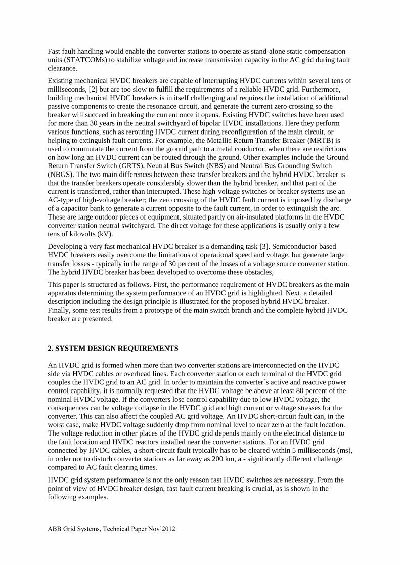
ABB Grid Systems, Technical Paper Nov’2012
Fast fault handling would enable the converter stations to operate as stand-alone static compensation
units (STATCOMs) to stabilize voltage and increase transmission capacity in the AC grid during fault
clearance.
Existing mechanical HVDC breakers are capable of interrupting HVDC currents within several tens of
milliseconds, [2] but are too slow to fulfill the requirements of a reliable HVDC grid. Furthermore,
building mechanical HVDC breakers is in itself challenging and requires the installation of additional
passive components to create the resonance circuit, and generate the current zero crossing so the
breaker will succeed in breaking the current once it opens. Existing HVDC switches have been used
for more than 30 years in the neutral switchyard of bipolar HVDC installations. Here they perform
various functions, such as rerouting HVDC current during reconfiguration of the main circuit, or
helping to extinguish fault currents. For example, the Metallic Return Transfer Breaker (MRTB) is
used to commutate the current from the ground path to a metal conductor, when there are restrictions
on how long an HVDC current can be routed through the ground. Other examples include the Ground
Return Transfer Switch (GRTS), Neutral Bus Switch (NBS) and Neutral Bus Grounding Switch
(NBGS). The two main differences between these transfer breakers and the hybrid HVDC breaker is
that the transfer breakers operate considerably slower than the hybrid breaker, and that part of the
current is transferred, rather than interrupted. These high-voltage switches or breaker systems use an
AC-type of high-voltage breaker; the zero crossing of the HVDC fault current is imposed by discharge
of a capacitor bank to generate a current opposite to the fault current, in order to extinguish the arc.
These are large outdoor pieces of equipment, situated partly on air-insulated platforms in the HVDC
converter station neutral switchyard. The direct voltage for these applications is usually only a few
tens of kilovolts (kV).
Developing a very fast mechanical HVDC breaker is a demanding task [3]. Semiconductor-based
HVDC breakers easily overcome the limitations of operational speed and voltage, but generate large
transfer losses - typically in the range of 30 percent of the losses of a voltage source converter station.
The hybrid HVDC breaker has been developed to overcome these obstacles,
This paper is structured as follows. First, the performance requirement of HVDC breakers as the main
apparatus determining the system performance of an HVDC grid is highlighted. Next, a detailed
description including the design principle is illustrated for the proposed hybrid HVDC breaker.
Finally, some test results from a prototype of the main switch branch and the complete hybrid HVDC
breaker are presented.
2. SYSTEM DESIGN REQUIREMENTS
An HVDC grid is formed when more than two converter stations are interconnected on the HVDC
side via HVDC cables or overhead lines. Each converter station or each terminal of the HVDC grid
couples the HVDC grid to an AC grid. In order to maintain the converter`s active and reactive power
control capability, it is normally requested that the HVDC voltage be above at least 80 percent of the
nominal HVDC voltage. If the converters lose control capability due to low HVDC voltage, the
consequences can be voltage collapse in the HVDC grid and high current or voltage stresses for the
converter. This can also affect the coupled AC grid voltage. An HVDC short-circuit fault can, in the
worst case, make HVDC voltage suddenly drop from nominal level to near zero at the fault location.
The voltage reduction in other places of the HVDC grid depends mainly on the electrical distance to
the fault location and HVDC reactors installed near the converter stations. For an HVDC grid
connected by HVDC cables, a short-circuit fault typically has to be cleared within 5 milliseconds (ms),
in order not to disturb converter stations as far away as 200 km, a - significantly different challenge
compared to AC fault clearing times.
HVDC grid system performance is not the only reason fast HVDC switches are necessary. From the
point of view of HVDC breaker design, fast fault current breaking is crucial, as is shown in the
following examples.
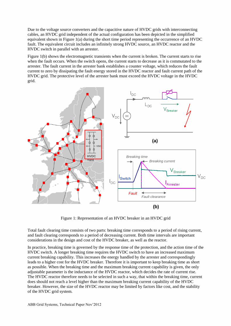
ABB Grid Systems, Technical Paper Nov’2012
Due to the voltage source converters and the capacitive nature of HVDC grids with interconnecting
cables, an HVDC grid independent of the actual configuration has been depicted in the simplified
equivalent shown in Figure 1(a) during the short time period representing the occurrence of an HVDC
fault. The equivalent circuit includes an infinitely strong HVDC source, an HVDC reactor and the
HVDC switch in parallel with an arrester.
Figure 1(b) shows the electromagnetic transients when the current is broken. The current starts to rise
when the fault occurs. When the switch opens, the current starts to decrease as it is commutated to the
arrester. The fault current in the arrester bank establishes a counter voltage, which reduces the fault
current to zero by dissipating the fault energy stored in the HVDC reactor and fault current path of the
HVDC grid. The protective level of the arrester bank must exceed the HVDC voltage in the HVDC
grid.
Figure 1: Representation of an HVDC breaker in an HVDC grid
Total fault clearing time consists of two parts: breaking time corresponds to a period of rising current,
and fault clearing corresponds to a period of decreasing current. Both time intervals are important
considerations in the design and cost of the HVDC breaker, as well as the reactor.
In practice, breaking time is governed by the response time of the protection, and the action time of the
HVDC switch. A longer breaking time requires the HVDC switch to have an increased maximum
current breaking capability. This increases the energy handled by the arrester and correspondingly
leads to a higher cost for the HVDC breaker. Therefore it is important to keep breaking time as short
as possible. When the breaking time and the maximum breaking current capability is given, the only
adjustable parameter is the inductance of the HVDC reactor, which decides the rate of current rise.
The HVDC reactor therefore needs to be selected in such a way, that within the breaking time, current
does should not reach a level higher than the maximum breaking current capability of the HVDC
breaker. However, the size of the HVDC reactor may be limited by factors like cost, and the stability
of the HVDC grid system.
Fault clearance
Breaking current
Breaking time
VSC
HVDC
Yard
Fault
(a)
(b)
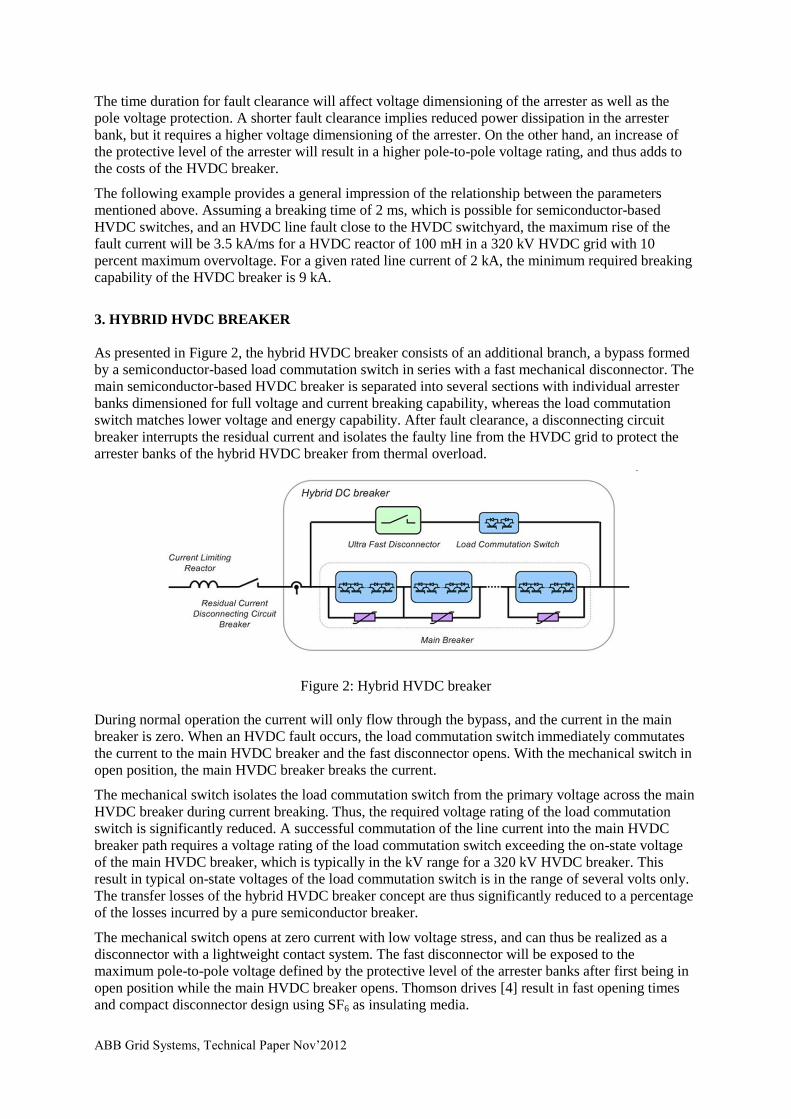
ABB Grid Systems, Technical Paper Nov’2012
The time duration for fault clearance will affect voltage dimensioning of the arrester as well as the
pole voltage protection. A shorter fault clearance implies reduced power dissipation in the arrester
bank, but it requires a higher voltage dimensioning of the arrester. On the other hand, an increase of
the protective level of the arrester will result in a higher pole-to-pole voltage rating, and thus adds to
the costs of the HVDC breaker.
The following example provides a general impression of the relationship between the parameters
mentioned above. Assuming a breaking time of 2 ms, which is possible for semiconductor-based
HVDC switches, and an HVDC line fault close to the HVDC switchyard, the maximum rise of the
fault current will be 3.5 kA/ms for a HVDC reactor of 100 mH in a 320 kV HVDC grid with 10
percent maximum overvoltage. For a given rated line current of 2 kA, the minimum required breaking
capability of the HVDC breaker is 9 kA.
3. HYBRID HVDC BREAKER
As presented in Figure 2, the hybrid HVDC breaker consists of an additional branch, a bypass formed
by a semiconductor-based load commutation switch in series with a fast mechanical disconnector. The
main semiconductor-based HVDC breaker is separated into several sections with individual arrester
banks dimensioned for full voltage and current breaking capability, whereas the load commutation
switch matches lower voltage and energy capability. After fault clearance, a disconnecting circuit
breaker interrupts the residual current and isolates the faulty line from the HVDC grid to protect the
arrester banks of the hybrid HVDC breaker from thermal overload.
Figure 2: Hybrid HVDC breaker
During normal operation the current will only flow through the bypass, and the current in the main
breaker is zero. When an HVDC fault occurs, the load commutation switch immediately commutates
the current to the main HVDC breaker and the fast disconnector opens. With the mechanical switch in
open position, the main HVDC breaker breaks the current.
The mechanical switch isolates the load commutation switch from the primary voltage across the main
HVDC breaker during current breaking. Thus, the required voltage rating of the load commutation
switch is significantly reduced. A successful commutation of the line current into the main HVDC
breaker path requires a voltage rating of the load commutation switch exceeding the on-state voltage
of the main HVDC breaker, which is typically in the kV range for a 320 kV HVDC breaker. This
result in typical on-state voltages of the load commutation switch is in the range of several volts only.
The transfer losses of the hybrid HVDC breaker concept are thus significantly reduced to a percentage
of the losses incurred by a pure semiconductor breaker.
The mechanical switch opens at zero current with low voltage stress, and can thus be realized as a
disconnector with a lightweight contact system. The fast disconnector will be exposed to the
maximum pole-to-pole voltage defined by the protective level of the arrester banks after first being in
open position while the main HVDC breaker opens. Thomson drives [4] result in fast opening times
and compact disconnector design using SF6 as insulating media.

ABB Grid Systems, Technical Paper Nov’2012
Proactive control of the hybrid HVDC breaker allows it to compensate for the time delay of the fast
disconnector, if the opening time of the disconnector is less than the time required for selective
protection. As shown in Figure 3, proactive current commutation is initiated by the hybrid HVDC
breaker`s built-in overcurrent protection as soon as the HVDC line current exceeds a certain
overcurrent level. The main HVDC breaker delays current breaking until a trip signal of the selected
protection is received or the faulty line current is close to the maximum breaking current capability of
the main HVDC breaker.
To extend the time before the self-protection function of the main HVDC breaker trips the hybrid
HVDC breaker, the main HVDC breaker may operate in current limitation mode prior to current
breaking. The main HVDC breaker controls the voltage drop across the HVDC reactor to zero to
prevent a further rise in the line current. Pulse mode operation of the main HVDC breaker or
sectionalizing the main HVDC breaker as shown in Figure 3 will allow adapting the voltage across the
main HVDC breaker to the instantaneous HVDC voltage level of the HVDC grid. The maximum
duration of the current limiting mode depends on the energy dissipation capability of the arrester
banks.
Figure 3: Proactive control of hybrid HVDC breaker. LCS denotes load commutation switch
On-line supervision allowing maintenance on demand is achieved by scheduled current transfer of the
line current from the bypass into the main HVDC current breaker during normal operation, without
disturbing or interrupting the power transfer in the HVDC grid.
Fast backup protection similar to pure semiconductor breakers is possible for hybrid HVDC breakers
applied to HVDC switchyards. Due to the proactive mode, over-currents in the line or superior
switchyard protection will activate the current transfer from the bypass into the main HVDC breaker
or possible backup breakers prior to the trip signal of the backup protection. In the case of a breaker
failure, the backup breakers are activated almost instantaneously, typically within less than 0.2 ms.
This will avoid major disturbances in the HVDC grid, and keep the required current-breaking
capability of the backup breaker at reasonable values. If not utilized for backup protection, the hybrid
HVDC breakers automatically return to normal operation mode after the fault is cleared.
PROTOTYPE DESIGN OF THE HYBRID HVDC BREAKER
The hybrid HVDC breaker is designed to achieve a current breaking capability of 9.0 kA in an HVDC
grid with rated voltage of 320 kV and rated HVDC transmission current of 2 kA. The maximum
current breaking capability is independent of the current rating and depends on the design of the main
Main HVDC Breaker
Max. Current Protection
Max. Breaking Current
Proactive Switching
LCS opens
Current Limiting
Fast Disconnector in open position
t (ms) Selective Protection
Fault
Main HVDC Breaker Max. Temperature Protection
External trip signal of Selective Protection to
Main HVDC Breaker
I (A)
Delay
ABB Grid Systems, Technical Paper Nov’2012
HVDC breaker only. The fast disconnector and main HVDC breaker are designed for switching
voltages exceeding 1.5 p.u. in consideration of fast voltage transients during current breaking.
The main HVDC breaker consists of several HVDC breaker cells with individual arrester banks
limiting the maximum voltage across each cell to a specific level during current breaking. Each HVDC
breaker cell contains four HVDC breaker stacks as shown in Figure 4. Two stacks are required to
break the current in either current direction.
Figure 4: Design of 80kV main HVDC breaker cell
Each stack is composed of up to 20 series connected IGBT (insulated gate bipolar transistor) HVDC
breaker positions. Due to the large di/dt stress during current breaking, a mechanical design with low
stray inductance is required. Application of press pack IGBTs with 4.5 kV voltage rating [6] enables a
compact stack design and ensures a stable short circuit failure mode in case of individual component
failure. Individual RCD snubbers across each IGBT position ensure equal voltage distribution during
current breaking. Optically powered gate units enable operation of the IGBT HVDC breaker
independent of current and voltage conditions in the HVDC grid. A cooling system is not required for
the IGBT stacks, since the main HVDC breaker cells are not exposed to the line current during normal
operation.
For the design of the auxiliary HVDC breaker, one IGBT HVDC breaker position for each current
direction is sufficient to fulfill the requirements of the voltage rating. Parallel connection of IGBT
modules increases the rated current of the hybrid HVDC breaker. Series connected, redundant IGBT
HVDC breaker positions improve the reliability of the auxiliary HVDC breaker. A matrix of 3x3
IGBT positions for each current direction is chosen for the present design. Since the auxiliary HVDC
breaker is continuously exposed to the line current, a cooling system is required. Besides water
cooling, air-forced cooling can be applied, due to relatively low losses in the range of several tens of
kW only.
5. TEST RESULTS MAIN BREAKER
During the design of the hybrid HVDC breaker prototype, different tests were performed in order to
verify expected performance. The first test setup reported earlier focuses mainly on the control of
semiconductor devices and their current breaking capability. The second test setup verifies both the
voltage and current capability of one cell of the main HVDC breaker. The ongoing extension of this
test setup will focus on the overall performance of the hybrid HVDC breaker. Due to big differences in
voltage levels in the test setup, construction of the test circuits is quite different but the test procedure
is similar.
A scaled-down prototype of the main breaker cell with three series connected IGBT modules and a
common arrester bank was used to verify the current-breaking capability of 4.5 kV StakPak IGBTs [6]
HVDC Breaker Cell
IGBT HVDC Breaker Position
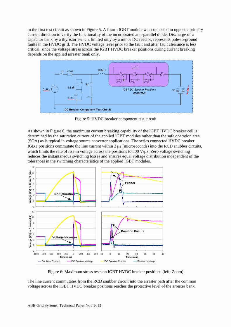
ABB Grid Systems, Technical Paper Nov’2012
in the first test circuit as shown in Figure 5. A fourth IGBT module was connected in opposite primary
current direction to verify the functionality of the incorporated anti-parallel diode. Discharge of a
capacitor bank by a thyristor switch, limited only by a minor DC reactor, represents pole-to-ground
faults in the HVDC grid. The HVDC voltage level prior to the fault and after fault clearance is less
critical, since the voltage stress across the IGBT HVDC breaker positions during current breaking
depends on the applied arrester bank only.
Figure 5: HVDC breaker component test circuit
As shown in Figure 6, the maximum current breaking capability of the IGBT HVDC breaker cell is
determined by the saturation current of the applied IGBT modules rather than the safe operation area
(SOA) as is typical in voltage source converter applications. The series connected HVDC breaker
IGBT positions commutate the line current within 2 s (microseconds) into the RCD snubber circuits,
which limits the rate of rise in voltage across the positions to 300 V/s. Zero voltage switching
reduces the instantaneous switching losses and ensures equal voltage distribution independent of the
tolerances in the switching characteristics of the applied IGBT modules.
Figure 6: Maximum stress tests on IGBT HVDC breaker positions (left: Zoom)
The line current commutates from the RCD snubber circuit into the arrester path after the common
voltage across the IGBT HVDC breaker positions reaches the protective level of the arrester bank.
DC Breaker Component Test Circuit, 19. January 2010
Voltag
e o
r C
urr
ent
Snubber Current DC Breaker Voltage DC Breaker Current Position Voltage
DC Breaker Component Test Circuit 19. January - Failure of IGBT Position #1
-2
0
2
4
6
8
10
12
-1000 -800 -600 -400 -200 0 200 400 600
Time in us
Vo
latg
e (
kV
) o
r C
urr
en
t (k
A)
Snubber Current in A IGBT Breaker Voltage in V Breaker Current in A IGBT Position Voltage in V
DC Breaker Component Test Circuit, 19. January 2010
-2
0
2
4
6
8
10
12
-10 0 10 20 30 40 50 60
Time in us
Vo
ltag
e o
r C
urr
en
t
Snubber Current DC Breaker Voltage DC Breaker Current Position Voltage
DC Breaker Component Test Circuit 19. January - Failure of IGBT Position #1
-2
0
2
4
6
8
10
12
-10 0 10 20 30 40 50 60
Time in us
Vo
latg
e o
r C
urr
en
t
Snubber Current in A IGBT Breaker Voltage in V Breaker Current in A IGBT Position Voltage in V
No Saturation
DC Breaker Component Test Circuit, 19. January 2010
-2
0
2
4
6
8
10
12
-1000 -800 -600 -400 -200 0 200 400 600
Time in us
Vo
ltag
e (
kV
) o
r C
urr
en
t (k
A)
Snubber Current DC Breaker Voltage DC Breaker Current Position Voltage
Voltage Increase
Position Failure
Proper Commutation

ABB Grid Systems, Technical Paper Nov’2012
The IGBT HVDC breaker positions passed the stress tests for breaking currents below 10 kA. For
higher currents, the IGBT saturation current level is reached by the internal current limitation in the
breaker, causing an immediate voltage drop across the IGBT modules. During a purposely destructive
test, the resulting internal heat dissipation within the IGBT module destroys the encapsulated IGBT
chips. Due to the use of presspack IGBTs, a reliable short circuit without mechanical destruction of the
failed IGBT module is enabled. Since only one of the IGBT modules failed during the test, the fault
can still be cleared by the two other modules.
The nominal HVDC voltage per IGBT HVDC breaker cell is 80 kV. Due to the high voltage level, the
second test setup requires a significantly larger space. In Figure 7, the test circuit for the hybrid HVDC
breaker concept is shown. A ±150 kV HVDC switchyard supplies the containerized test equipment to
verify the functionality of the main IGBT HVDC breaker represented by two series connected IGBT
HVDC breaker stacks and a common arrester bank. The desired HVDC voltage level is built up by
charging the capacitor bank C1. The reactor L1 is selected to give the expected current derivative
(di/dt) during a short-circuit fault. The short-circuit fault is initiated by the triggered spark gap Q5.
Figure 7: ABB’s containerized HVDC breaker test circuit
Figure 8 shows a typical test result. A maximum breaking current of over 9 kA is verified. The voltage
across the HVDC breaker cell exceeds 120 kV during current commutation. The breaking capability of
one 80 kV HVDC breaker cell thus exceeds 1 GVA. Furthermore, equal voltage distribution with a
maximum voltage drop of 3.3 kV and a spread of less than 10 percent was only observed for the
individual IGBT HVDC breaker positions in the HVDC breaker cell.
Figure 8: Verification of modular IGBT HVDC breaker cell
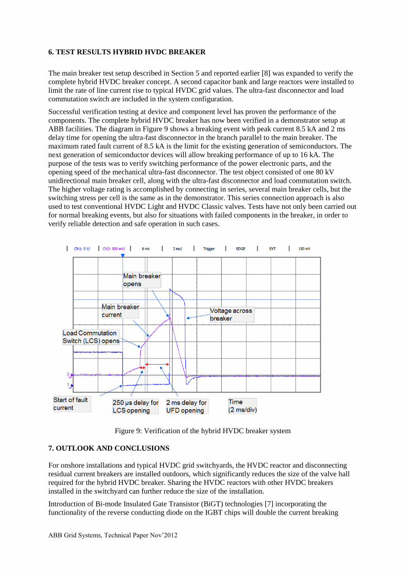
ABB Grid Systems, Technical Paper Nov’2012
6. TEST RESULTS HYBRID HVDC BREAKER
The main breaker test setup described in Section 5 and reported earlier [8] was expanded to verify the
complete hybrid HVDC breaker concept. A second capacitor bank and large reactors were installed to
limit the rate of line current rise to typical HVDC grid values. The ultra-fast disconnector and load
commutation switch are included in the system configuration.
Successful verification testing at device and component level has proven the performance of the
components. The complete hybrid HVDC breaker has now been verified in a demonstrator setup at
ABB facilities. The diagram in Figure 9 shows a breaking event with peak current 8.5 kA and 2 ms
delay time for opening the ultra-fast disconnector in the branch parallel to the main breaker. The
maximum rated fault current of 8.5 kA is the limit for the existing generation of semiconductors. The
next generation of semiconductor devices will allow breaking performance of up to 16 kA. The
purpose of the tests was to verify switching performance of the power electronic parts, and the
opening speed of the mechanical ultra-fast disconnector. The test object consisted of one 80 kV
unidirectional main breaker cell, along with the ultra-fast disconnector and load commutation switch.
The higher voltage rating is accomplished by connecting in series, several main breaker cells, but the
switching stress per cell is the same as in the demonstrator. This series connection approach is also
used to test conventional HVDC Light and HVDC Classic valves. Tests have not only been carried out
for normal breaking events, but also for situations with failed components in the breaker, in order to
verify reliable detection and safe operation in such cases.
Figure 9: Verification of the hybrid HVDC breaker system
7. OUTLOOK AND CONCLUSIONS
For onshore installations and typical HVDC grid switchyards, the HVDC reactor and disconnecting
residual current breakers are installed outdoors, which significantly reduces the size of the valve hall
required for the hybrid HVDC breaker. Sharing the HVDC reactors with other HVDC breakers
installed in the switchyard can further reduce the size of the installation.
Introduction of Bi-mode Insulated Gate Transistor (BiGT) technologies [7] incorporating the
functionality of the reverse conducting diode on the IGBT chips will double the current breaking

ABB Grid Systems, Technical Paper Nov’2012
capability of existing presspack modules. With maximum breaking currents of up to 16 kA and
operating times within 2 ms including the time delay of the protection system, proactive hybrid HVDC
breakers are well suited for use in HVDC switchyards to prevent the collapse of multi-terminal HVDC
systems due to HVDC line faults.
Fast, reliable and nearly zero loss HVDC breakers and current limiters based on the hybrid HVDC
breaker concept have been verified at component and system levels at ABB’s high power laboratories
in Sweden and Switzerland, for HVDC voltages up to 320 kV and rated currents of 2.6 kA. Thus
HVDC grids can now be planned. The next step is to deploy the breaker in a real HVDC transmission
line to test under continuous full load conditions.
BIBLIOGRAPHY
[1] E. Koldby, M. Hyttinen “Challenges on the Road to an Offshore HVDC Grid,” (Nordic Wind
Power Conference, Bornholm, Sept. 2009)
[2] Å. Ekström, H. Härtel, H.P. Lips, W. Schultz “Design and testing of an HVDC circuit breaker,”
(Cigré session 1976, paper 13-06)
[3] C.M. Franck “HVDC Circuit Breakers: A Review Identifying Future Research Needs,” (IEEE
Trans. on Power Delivery, vol. 26, pp. 998-1007, April 2011)
[4] J. Magnusson, O. Hammar, G. Engdahl “Modelling and Experimental Assessment of Thomson
Coil Actuator System for Ultra Fast Mechanical Switches for Commutation of Load Currents,”
(International Conference on New Actuators and Drive Systems, Bremen, 14-16 Juni 2010)
[5] G. Asplund “HVDC switch for current limitation in a HVDC transmission with voltage source
converters,” (European Patent EP0867998B1)
[6] S. Eicher, M. Rahimo, E. Tsyplakov, D. Schneider, A. Kopta, U. Schlapbach, E. Caroll “4.5kV
Press Pack IGBT Designed for Ruggedness and Reliability,” (IAS, Seattle, October 2004)
[7] M. Rahimo, A. Kopta, U. Schlapbach, J. Vobecky, R. Schnell, S. Klaka “The Bi-mode Insulated
Gate Transistor (BiGT) A potential technology for higher power applications,” (Proc. ISPSD09,
p. 283, 2009)
[8] J. Häfner, B. Jacobson, ” Proactive Hybrid HVDC Breakers - A key innovation for reliable
HVDC grids,” (Cigré Bologna, Paper 0264, 2011)