the game of simon
TRANSCRIPT
The Game Of Simon
Alex Grammar Daniel Bujalski
Thomas Oh
4/18/2010

Introduction The team designed and built an on-chip implementation of the classic pattern matching game of Simon. The chip is designed to generate a random sequence of colors (from the set of red, green, blue, and yellow) for the player to later try to match. This sequence is stored in an internal SRAM memory block and is played back to the user before waiting for input. The player's input comes into the system through four external buttons (one for each color), which are assumed to be debounced by external hardware. The player is required to press the buttons in the order that the system outputs the colors as a test of the player's memory. The internal memory is large enough to hold a color sequence 63 "stages" long, so if the user reaches that point, the game declares a win and all output lights are turned on. If at any time during input the user presses an incorrect light, the game is lost and only two lights are lit (red and green). At all times, the chip outputs the user’s score which is equal to the number of stages in the current sequence. To start or restart the game, the user must press a reset button, which erases the old sequence and begins the game anew.
Specifications Theory of Operation: The device is simply a complex finite state machine, following a distinct process flow to carry out the game's functions. When first turned on, the chip will experience some extraneous processing for the first few nanoseconds, but will quickly revert to a "do-nothing" state. In addition, a separate 2-bit counter, which will be afterwards referred to as RNG_counter, will be initialized that will run for the duration of the device's time powered. The game is initialized by a reset pulse triggered by an external button. This resets all relevant parameters in the logic: the score, the reference position for the memory, and the sequence terms. The logical state machine reverts to the state START, which denotes the start of game iteration. However, RNG_counter is not reset by this action. Upon reaching the START state, the logic sets an enable write_en. This bit tells the memory module to write to the memory address specified by the valuecurr_pos (which is equal to the current score, which is 0 to start). The value written comes directly from the output of RNG_counter, meaning a "random" number between 0 and 3 will be passed. The number represents a certain color: 0 for red, 1 for blue, 2 for green, and 3 for yellow. Once this is done, the FSM simply moves on. The next states handle the output logic, which output the terms of the sequence for the player to see. The first state here is PRE-OUTPUT, which prepares certain parameters for outputting - in particular, curr_pos is reset to zero and score is incremented. Following this comes OUTPUT_SEQ, which outputs a term in the sequence. This state will read and output the

contents of memory at position curr_pos, increment curr_pos, and return to itself until curr_pos equals score (ie: the sequence has been outputted). At this point, the state POST_OUT will be called that simply resets curr_pos again in preparation for input. At this point, the FSM goes to the state INPUT_SEQ, which waits for user input. During this state, the logic continually reads the current stage from memory and enables input detection. At this point, the player may press the corresponding keys and the logic will accept them. Upon detecting a key press, the FSM passes to state CHECK, which checks the input against the sequence (and determines a loss if necessary). A successful input calls CHECK_WIN, which checks to see if the end of the sequence has been reached and, if so, returns to START for the next iteration. Should score ever equal 63 at this point, the WIN state will be called here. Should the player successfully complete one iteration of the sequence, the FSM continues with the next iteration (with an additional stage in the sequence). This continues until the player wins (WIN), loses (LOSE), or presses the reset. It should also be mentioned that, regarding our logic structure, testing the game would be difficult to do manually. Therefore, our testbench had to be made "reactive" to the sequence outputs somehow. In order to facilitate this, a 3-bit quantity cheat_out was added as an output. During INPUT_SEQ, cheat_out will consist of a 1 followed by the 2 bits corresponding to the color in the sequence (ie: a red would be 100, while a blue would be 101). At all other times, this would be 000. In this way, the testbench can recognize when and what it should provide as input to the system. Pin Name Direction Planned Pin Number(s) VDD Input/Output 1,5,7,15,17,25,34,37,39 GND Input/Output 2,4,6,14,16,26,35,36,38,40 score<6:0> Output 33-27 (0 at pin 33) ph1 Input 8 ph2 Input 9 red Input 11 yellow Input 12 green Input 13 blue Input 10 r_out Output 21 y_out Output 22 g_out Output 24 b_out Output 23 reset Input 3 cheat_out<2:0> Output 20-18 (0 at pin 20)
Table 1:List of Chip Pin Designations and Directions

Floorplan When proposing our project, we made an initial floorplan to estimate how much space the logic blocks would require. Since our experience with layout sizing was fairly limited, we were forced to use some guesswork to make our estimates of the block sizes, albeit with some small research to back the estimates up a little. However, immediately upon beginning layout work, it was obvious that the estimates were wrong. Initially, we had guessed at using only a very small fraction (maybe 5-10%) of the space within the padframe with 4-5 logic blocks, the largest of which was in the range of 90λ x 1500λ. Although we still had the same number of blocks in the final layout, the sizes were much larger, to the point where we would fill most (if not all) of the available space. In addition, we discovered a significant problem with the memory module in that it was too tall for the padframe (it being close to 5500λ in height). As it was, the only block that was reasonably close to estimates was RNG_counter, which we can attribute to our having some knowledge of the counter hardware. However, lack of experience combined with synthesis issues completely threw off our other estimates. Given time, however, the final layout could still fit within the padframe if the memory were to be split in half.
Verification
The simon_top Verilog module (appendix A) will successfully complete the test bench (appendix B). The test bench tests all cases of the logic by constructing a winning scenario, where the inputs always match the sequence until the sequence reaches 63 stages, and a losing scenario, where the testbench deliberately enters an incorrect input. In addition, we tested the randomness of the output from RNG_counter by pulling values from it at random times using another simple testbench, since the deterministic nature of Verilog prevented us from achieving true randomness in the original testbench. The completed schematic of the simon game derived from the Verilog passes the same testbench as well, indicating that our schematics are correct and match the desired logic. The second stage of verification involved the testing of the layouts derived from schematic. The team’s layouts for all cells that make up simon_top (the top-level or core module) successfully passed both DRC and LVS, indicating that the layouts matched the schematics and would operate as desired. In addition, the padframe we assembled also passed DRC and LVS. Unfortunately due to the oversight in the configuration of the memory layout and a lack of time, we were not able to combine the padframe and simon_top into the completed chip layout and thus have no CIF results. However, we do know it would be possible, given time, to change the aspect ratio of the memory layout such that the core would fit in the padframe, which would allow for eventual manufacture.

Post-fabrication Test Plan Since the final chip was unable to be completed, manufacture is not currently possible. However, had it been manufactured, the following test plan would be necessary to verify chip integrity. The first step in post-fab testing would be to check the functionality of the reset command after powering on. A high reset will set the output score to 0000000, and a single color should be shown to the user. The output cheat_out would also indicate this color as the device waits for input. Should this prove successful, the next step would be to try the "win" case, wherein the tester would play through all 63 stages. This could be easily done with the use of the cheat_out pins indicating the correct button to press. After that the tester should play through a "lose" scenario, which involved pressing correct input for several stages before deliberately failing. This proves the functionality of the "lose" logic as well as checks to see if a new game is generated with a different sequence than the first. Finally the tester could try to “break” the game by mashing the input buttons, or pressing multiple buttons at the same time. If the chip does not lock up, then the device can be considered to have passed post-fabrication testing. While performing this test by hand is time consuming, a simple microcontroller device could be constructed to utilize the cheat out pins to play the game automatically and monitor the “light out” pins to determine winning and losing.

Design Time Design Phase Hours Spent Proposal 4 hours Verilog 8 hours Schematic 30 hours Layout 48 hours
Table 2:- Distribution of the amount of time spent on each design phase by the team File Locations All files are in Daniel Bujalski's chips directory (dbujalski). Verilog modules - ~/IC_CAD/cadence/simon_top.v Testbench - ~/IC_CAD/cadence/simon_top_run1/testfixture.template Synthesis results - ~/IC_CAD/synth Cadence libraries - ~/IC_CAD/cadence Chip plot (actually simon_top) - ~/IC_CAD/cadence/chip.pdf Report PDF - ~/IC_CAD/cadence/The_Game_of_Simon.pdf
References Harris, David M., and Neil H. E. Weste. CMOS VLSI Design: A Circuits and Systems Perspective, 4th Edition. Massachusetts: Addison-Wesley, 2010.

Appendix A - Verilog Modules `timescale 1ns / 1ps //Module implementing the simon game //Written by Daniel Bujalski, Thomas Oh, and Alex Grammar module simon_game (input red, yellow, green, blue, //Color inputs ph1, ph2, //Clock inputs (ph1 is opposite of ph2) reset, //Reset pin output r_out, y_out, g_out, b_out,//Color outputs output [6:0] score, //Score output (ALSO keeps track of sequence length) output [2:0] cheat_out); //Output for testing only, outputs current contents of parameter START = 3'b000; parameter PRE_OUTPUT = 3'b001; parameter OUTPUT_SEQ = 3'b010; parameter INPUT_SEQ = 3'b011; parameter CHECK = 3'b100; parameter LOSE = 3'b101; parameter RESET = 3'b110; parameter WIN = 3'b111; //Various wires/regs wire input_en; wire [6:0] curr_pos; //Current position reference in the simon sequence memory wire [1:0] RNG_out; //Output of the random number generator wire [1:0] mem_in; //Input for writing to the sequence memory wire write_en; //Enable for writing to the sequence memory wire [1:0] mem_out; //Output from memory (contents of mem at curr_pos) wire [2:0] button_out; //Output from input handler (ultimately from the 'buttons') //Instances RNG_counter RNG (ph1, ph2, RNG_out); //Random number generator (RNG) instance //Simon sequence memory instance: sequence_mem simon_mem (curr_pos, mem_in, write_en, mem_out); //Simon input handler instance: input_handler simon_in (red, green, blue, yellow, input_en, button_out); //Simon processor instance simonprocessing ssm(ph1,ph2,reset,button_out,RNG_out,mem_out,write_en,r_out,y_out,g_out, b_out,input_en, mem_in,score,curr_pos,cheat_out); endmodule

//------------------------------------------------------------------------------ //Processor for simon game logic - includes controller and datapath //------------------------------------------------------------------------------ module simonprocessing(input ph1, ph2, reset, input [2:0] button_out, input [1:0] RNG_out, mem_out, output write_en, read_en, r_out, y_out, g_out, b_out, input_en, output [1:0] mem_in, output [6:0] score, curr_pos, output [2:0] cheat_out); wire scoreinc,curr_posinc,resetcurr_pos; //Enables for changing score and curr_pos simoncontroller sc(ph1,ph2,reset,button_out,mem_out,curr_pos,score,cheat_out,scoreinc curr_posinc, resetcurr_pos, write_en,read_en,input_en,r_out,g_out,b_out,y_out); simondatapath sdp(ph1,ph2,reset,curr_posinc,scoreinc,resetcurr_pos,RNG_out,score, curr_pos,mem_in); endmodule module simoncontroller(input ph1, ph2, reset, input [2:0] button_out, input [1:0] mem_out, input [6:0] curr_pos, score, output [2:0] cheat_out, output scoreinc, curr_posinc, resetcurr_pos, output write_en, read_en, input_en, output r_out, g_out, b_out, y_out); wire [3:0] state; simonstatelogic ssl(ph1,ph2,reset,curr_pos,score,button_out,mem_out,state); simonoutputlogic sol(state,mem_out,score,curr_pos,cheat_out,scoreinc,curr_posinc, resetcurr_pos,write_en,read_en,input_en,r_out,g_out,b_out,y_out); endmodule module simonstatelogic(input ph1, ph2, reset, input [6:0] curr_pos, score, input [2:0] button_out, input [1:0] mem_out, output [3:0] state); reg [3:0] nextstate; wire [3:0] ns, state_logic; parameter START = 4'b0111; parameter PRE_OUTPUT = 4'b0001; parameter OUTPUT_SEQ = 4'b0010; parameter POST_OUT = 4'b0011; parameter INPUT_SEQ = 4'b0100; parameter CHECK = 4'b0101; parameter CHECK_WIN = 4'b0110; parameter WIN = 4'b0000; parameter LOSE = 4'b1000;

mux2 #(4) resetmux(nextstate,START,reset,ns); flop #(4) statereg(ph1,ph2,ns,state_logic); assign state = state_logic; //next state logic always @ ( * ) begin case(state) //Start of the machine...adds a term to the sequence end START: nextstate = PRE_OUTPUT; //Prepares for outputs by changing score/curr_pos PRE_OUTPUT: nextstate = OUTPUT_SEQ; //Determines which color is next to output OUTPUT_SEQ: begin //If these match, we hit the end of the sequence if (score == curr_pos) begin nextstate = POST_OUT; //...so we move on end else begin nextstate = OUTPUT_SEQ; end end //Prepares for input watching POST_OUT: nextstate = INPUT_SEQ; //Seaches for input, only transitions on button-press INPUT_SEQ: begin //Button press goes to be checked if (button_out[2]) nextstate = CHECK; else //Otherwise keep lookin' nextstate = INPUT_SEQ; end //On a button press, checks against current part of sequence CHECK: begin if (button_out[1:0] == mem_out) //A match! nextstate = CHECK_WIN; //Check for a win else //A wrong button press means you lose! nextstate = LOSE; end //Check for the end of the sequence and/or a win (63 terms) CHECK_WIN: begin //End of the current sequence if (score == curr_pos) if (score == 7'b1000000) //If score reaches our max value, its a win nextstate = WIN; else //Otherwise, go to the beginning nextstate = START; else nextstate = INPUT_SEQ; end LOSE: nextstate = LOSE; //Loss... WIN: nextstate = WIN; //Win! default: nextstate = START; //Shouldn't happen endcase end endmodule
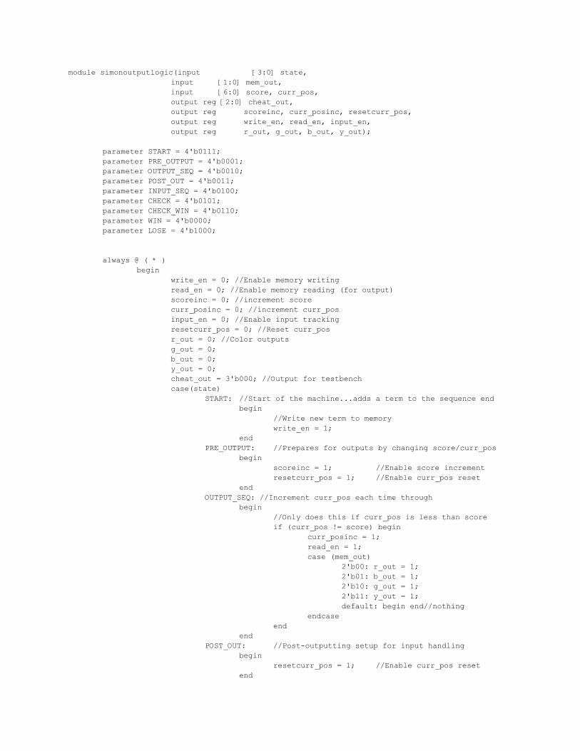
module simonoutputlogic(input [3:0] state, input [1:0] mem_out, input [6:0] score, curr_pos, output reg [2:0] cheat_out, output reg scoreinc, curr_posinc, resetcurr_pos, output reg write_en, read_en, input_en, output reg r_out, g_out, b_out, y_out); parameter START = 4'b0111; parameter PRE_OUTPUT = 4'b0001; parameter OUTPUT_SEQ = 4'b0010; parameter POST_OUT = 4'b0011; parameter INPUT_SEQ = 4'b0100; parameter CHECK = 4'b0101; parameter CHECK_WIN = 4'b0110; parameter WIN = 4'b0000; parameter LOSE = 4'b1000; always @ ( * ) begin write_en = 0; //Enable memory writing read_en = 0; //Enable memory reading (for output) scoreinc = 0; //increment score curr_posinc = 0; //increment curr_pos input_en = 0; //Enable input tracking resetcurr_pos = 0; //Reset curr_pos r_out = 0; //Color outputs g_out = 0; b_out = 0; y_out = 0; cheat_out = 3'b000; //Output for testbench case(state) START: //Start of the machine...adds a term to the sequence end begin //Write new term to memory write_en = 1; end PRE_OUTPUT: //Prepares for outputs by changing score/curr_pos begin scoreinc = 1; //Enable score increment resetcurr_pos = 1; //Enable curr_pos reset end OUTPUT_SEQ: //Increment curr_pos each time through begin //Only does this if curr_pos is less than score if (curr_pos != score) begin curr_posinc = 1; read_en = 1; case (mem_out) 2'b00: r_out = 1; 2'b01: b_out = 1; 2'b10: g_out = 1; 2'b11: y_out = 1; default: begin end//nothing endcase end end POST_OUT: //Post-outputting setup for input handling begin resetcurr_pos = 1; //Enable curr_pos reset end

INPUT_SEQ: //Looks for an input begin read_en = 1; //Read from memory for cheat_out input_en = 1; //Input handling enabled //Send out cheat_out for testbench cheat_out = {1'b0,mem_out} + 3'b100; end CHECK: //Upon a button press, perform actions related to it begin read_en = 1; input_en = 1; //Keep input enable high for check curr_posinc = 1; //Increment curr_pos in any case end CHECK_WIN: //Checks to see if player has won begin //Currently doesn't need to do anything end LOSE: begin //Player loses, light half the outputs r_out = 1'b1; b_out = 1'b0; g_out = 1'b1; y_out = 1'b0; end WIN: begin //Player wins, flash all outputs at once r_out = 1'b1; b_out = 1'b1; g_out = 1'b1; y_out = 1'b1; end default: begin //Shouldn't be reached end endcase end endmodule module simondatapath(input ph1, ph2, reset, input curr_posinc, scoreinc, resetcurr_pos, input [1:0] RNG_out, output [6:0] score, curr_pos, output [1:0] mem_in); flopenr #(7) curr_pos_flop(ph1, ph2, (reset || resetcurr_pos), curr_posinc, curr_pos+1'b1, curr_pos); flopenr #(7) score_flop(ph1, ph2, reset, scoreinc, score+1'b1, score); flop #(2) add_term_flop(ph1,ph2,RNG_out,mem_in); endmodule

//------------------------------------------------------------------------------ //RNG_counter to generate random numbers for sequence //------------------------------------------------------------------------------ module RNG_counter( input ph1, ph2, output [1:0] count_out); reg [1:0] count = 0; flop #(2) countflop(ph1,ph2,count,count_out); always @ ( * ) count <= count_out + 1; endmodule //------------------------------------------------------------------------------ //Sequence memory for storing the stages (note: does not have a read enable here //as it was introduced manually in schematic) //------------------------------------------------------------------------------ module sequence_mem(input [6:0] curr_pos, input [1:0] RNG_in, input write_en, output [1:0] color_out); reg [1:0] seq_mem[2**6:0]; //Write contents of RNG_in to memory location curr_pos //when write_en is set high (on edge) always @ (posedge write_en) seq_mem[curr_pos] <= RNG_in; //Module outputs the contents of memory at curr_pos assign color_out = seq_mem[curr_pos]; endmodule //------------------------------------------------------------------------------ //Input handler module for the simon game which avoids multiple inputs in series //------------------------------------------------------------------------------ module input_handler( input r, g, b, y, input en, output [2:0] color_out ); wire [2:0] mid; mux2 #(3) endmux(3'b000, mid, en, color_out); mux16 #(3) decodermux(3'b100,3'b101,3'b110,3'b111,3'b000,{y,g,b,r},mid); endmodule //Special mux for input (each bit of input is one of the lights) module mux16 #(parameter WIDTH = 8) (input [WIDTH-1:0] d0, d1, d2, d3, d4, input [3:0] s, output reg [WIDTH-1:0] y);

always @ ( * ) case(s) 4'b0001: y = d0; 4'b0010: y = d1; 4'b0100: y = d2; 4'b1000: y = d3; default: y = d4; endcase endmodule //Other useful blocks - flops, muxes, etc. module flop #(parameter WIDTH = 8) (input ph1, ph2, input [WIDTH-1:0] d, output [WIDTH-1:0] q); wire [WIDTH-1:0] mid; latch #(WIDTH) master(ph2, d, mid); latch #(WIDTH) slave(ph1, mid, q); endmodule module flopen #(parameter WIDTH = 8) (input ph1, ph2, en, input [WIDTH-1:0] d, output [WIDTH-1:0] q); wire [WIDTH-1:0] d2; mux2 #(WIDTH) enmux(q, d, en, d2); flop #(WIDTH) f(ph1, ph2, d2, q); endmodule module flopenr #(parameter WIDTH = 8) (input ph1, ph2, reset, en, input [WIDTH-1:0] d, output [WIDTH-1:0] q); wire [WIDTH-1:0] resetval, d2, mid; // assign resetval = 0; // mux3 #(WIDTH) enrmux(q, d, resetval, {reset, en}, d2); mux2 #(WIDTH) enmux(q, d, en, mid); //Used to be WIDTH'b0, but synthesis would not take it, so is at the moment a hard value // mux2 #(WIDTH) resetmux(mid,{WIDTH{1'b0}},reset,d2); // flop #(WIDTH) f(ph1, ph2, d2, q); flopr #(WIDTH) f(ph1, ph2, reset, mid, q); endmodule module flopr #(parameter WIDTH = 8) (input ph1, ph2, reset, input [WIDTH-1:0] d, output [WIDTH-1:0] q); wire [WIDTH-1:0] mid; latchr #(WIDTH) master(ph2, reset, d, mid);
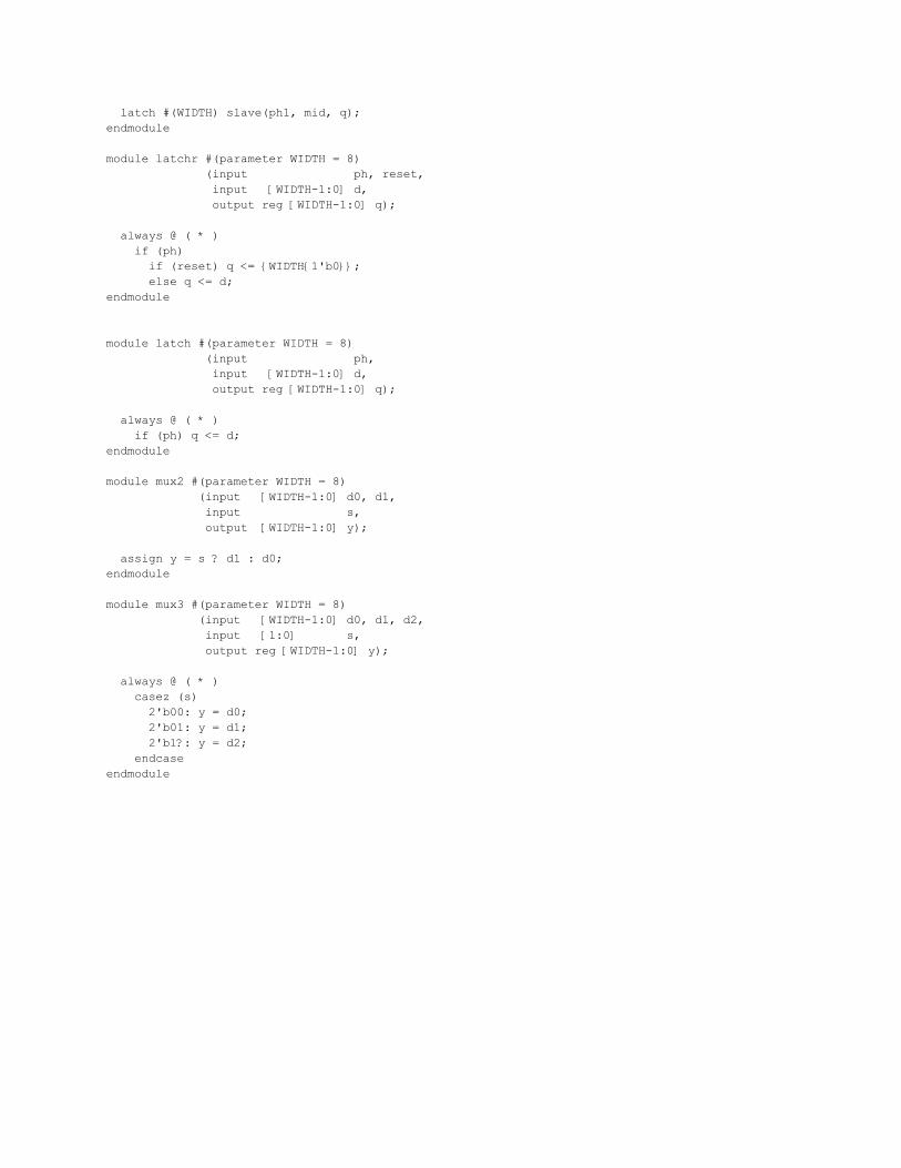
latch #(WIDTH) slave(ph1, mid, q); endmodule module latchr #(parameter WIDTH = 8) (input ph, reset, input [WIDTH-1:0] d, output reg [WIDTH-1:0] q); always @ ( * ) if (ph) if (reset) q <= {WIDTH{1'b0}}; else q <= d; endmodule module latch #(parameter WIDTH = 8) (input ph, input [WIDTH-1:0] d, output reg [WIDTH-1:0] q); always @ ( * ) if (ph) q <= d; endmodule module mux2 #(parameter WIDTH = 8) (input [WIDTH-1:0] d0, d1, input s, output [WIDTH-1:0] y); assign y = s ? d1 : d0; endmodule module mux3 #(parameter WIDTH = 8) (input [WIDTH-1:0] d0, d1, d2, input [1:0] s, output reg [WIDTH-1:0] y); always @ ( * ) casez (s) 2'b00: y = d0; 2'b01: y = d1; 2'b1?: y = d2; endcase endmodule

Appendix B - Testbench
`timescale 1ns / 1ps module test; reg r, y, g, b, reset; wire r_out, g_out, y_out, b_out; wire [6:0] score; wire [2:0] cheat_out; reg ph1, ph2; reg test_en = 0; reg lose_test_en = 0; //Simon game instance simon_top dut(b_out, cheat_out, g_out, r_out, score, y_out, b, g, ph1, ph2, r, reset, y); //Clock generation always begin ph1 = 0; ph2 = 0; #1; ph1 = 1; #4; ph1 = 0; #1; ph2 = 1; #4; ph2 = 0; end //Begin testing (enable win test) initial begin reset = 0; #5; #27; #1200; //Wait a bunch for easier viewing reset = 1; //Toggle reset to begin the game #27; reset = 0; test_en = 1;//And enable the test end //Testing logic - handles both win and lose tests always @ (posedge ph1) begin r = 0; b = 0; g = 0; y = 0; //If all outputs are set, the player has won...the win test has succeeded if (r_out && g_out && b_out && y_out && (score == 7'b1000000)) begin $display("Simon game has completed the winning test successfully."); $display("Commencing lose test after 7 stages..."); lose_test_en = 1; //Enable lose test, disable win test test_en = 0; reset = 1; #27; reset = 0; //Reset the game //If r and g outputs are set together ONLY, this signifies //a lose. For our test, it succeeds if the score is 7 when this happens. end else if (r_out && g_out && !y_out && !b_out &&(score == 3'b111)) begin $display("Simon game has completed the losing test successfully(?)."); reset = 1; #27; reset = 0; //All done

lose_test_en = 0; $finish; //Now, if win test is enabled...the testbench will use a cheat input from //the simon module to enter correct inputs every time. //NOTE: this only runs if cheat_out[2] (a validity bit) is set...so that //the testbench only sets the inputs when the simon module asks for them. end else if (test_en && cheat_out[2]) begin case(cheat_out[1:0]) //Set the appropriate input. 2'b00: begin r = 1; b = 0; g = 0; y = 0; end 2'b01: begin b = 1; r = 0; g = 0; y = 0; end 2'b10: begin g = 1; b = 0; r = 0; y = 0; end 2'b11: begin y = 1; b = 0; g = 0; r = 0; end default:; endcase //Lose test runs very similarly to the win test...save for one thing. end else if (lose_test_en && cheat_out[2]) begin //When we've gotten to a sequence of length 7, purposefully fail //by asserting an arbitrary input if (score == 3'b111) begin r = 1; //Red is cool :) end else begin case(cheat_out[1:0]) //Same as for win testing 2'b00: r = 1; 2'b01: b = 1; 2'b10: g = 1; 2'b11: y = 1; default:; endcase end //This last else clears the color inputs (since the simon module is not //ready for an input yet...denoted by cheat_out[2] being 0. end else if (!cheat_out[2]) begin r = 0; b = 0; g = 0; y = 0; end end endmodule

Appendix C - Schematics Note: Synthesized block schematics will not be shown for simplicity. These include RNG_counter, simonprocessing, and decodder6_64.
Core simon_top schematic:

Input handler decodermux schematic:

Custom leaf cell tristate_1 schematic:
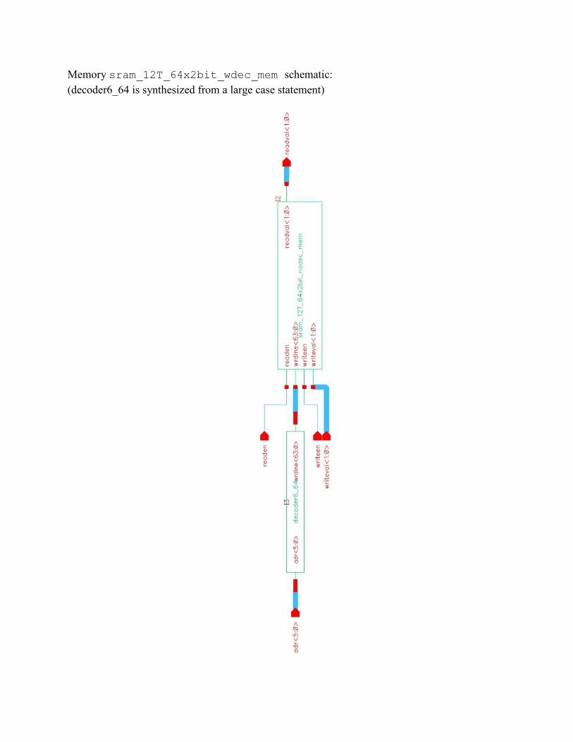
Memory sram_12T_64x2bit_wdec_mem schematic: (decoder6_64 is synthesized from a large case statement)

Memory sram_12T_64x2bit_nodec_mem schematic selection: (module to large to display fully, is actually two modules for two bits)

Memory sram_12T_1bit schematic:
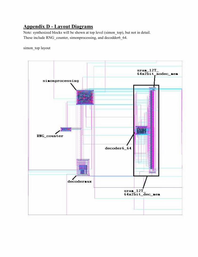
Appendix D - Layout Diagrams Note: synthesized blocks will be shown at top level (simon_top), but not in detail. These include RNG_counter, simonprocessing, and decodder6_64. simon_top layout

Input handler decodermux layout:

Custom leaf cell tristate_1 layout:

Memory sram_12T_64x2bit_nodec_mem partial layout:
Note pairs of SRAM blocks on the right, the layout of which follows this one.

Memory sram_12T_1bit layout: