the euromatic range - heatingsparesltd.com
TRANSCRIPT

Supplied By www.heating spares.co Tel. 0161 620 6677
OEM Instructionsfor DH Units
WARNING: THIS APPLIANCE MUST BE EARTHED
Euro Range OEM Issue 3 June 2002
The Euromatic RangeSeries 2

Supplied By www.heating spares.co Tel. 0161 620 6677
CONTENTS
Section Title Page
1. Introduction 32. Technical Data 43. General Requirements 84. Installation 95. Wiring Diagrams 116. Airflow Resistance 20
Tables Title Page
1. Dimensions 61a. Exhaust Fan Mounting Plate Inlet Diameters 62. Specifications 63.1 Injector Sizes & Burner Pressures
Natural Gas - Group H - G20 73.2 Injector Sizes & Burner Pressures
Propane - G31 73.3 Injector Sizes - Butane - G30 7
Figure Title Page
1a. Vertical - Top outlet flue arrangement 81b. Horizontal - Side outlet flue arrangement 81c. Horizontal - Top outlet flue arrangement 81d. Typical AHU Flue / Combustion Air 82. Controls Location 10
Wiring Diagram Page
Euromatic 15 -75 Single Stage Burner 11Euromatic 15 -75 Hi / Lo Burner 12Euromatic 15 -75 0-10V Modulating 13Euromatic 90 Single Stage Burner 14Euromatic 90 Hi / Lo Burner 15Euromatic 90 0-10V Modulating 16Euromatic 105-150 Single Stage Burner 17Euromatic 105-150 Hi / Lo Burner 18Euromatic 105-150 0-10V Modulating 19
Airflow Resisances
Euro 15-60 DH 20Euro 75-150 DH 21
Flue Components Page
Euro 15-60 DH Vertical flue arrangement 22Euro 15-60 DH Horizontal flue arrangement 23Euro 75-150 Vertical flue arrangement 24Euro 75-150 Horizontal flue arrangement 25Euro 15-150 DH Standard parts 26
2
Supplied By www.heating spares.co Tel. 0161 620 6677
1. INTRODUCTION The Euromatic DH range of gas fired air heaters cover aheat output range of 15kW to 150kW, have a closedcombustion circuit and are supplied complete with a fluesystem and are for installation into air handling and similarequipment. They are certified for use on Natural Gas, GroupH - G20, Propane - G31 and Butane - G30.Appliance Categories are Cat II2H3+.
The heaters are designed to be fitted into air handling andsimilar equipment.
Heaters are fitted as standard with atmospheric bar burners,a fully automatic control for ignition, flame sensing, gassupply control and safety functions, an internal exhaust fan,fan thermostat and limit thermostat and both inlet and outletduct connection spigots. As standard Natural Gas fired unitsare fitted with modulating burner controls operating at thedictate of an external 0-10V signal, at 0V the burners areturned off.
High/Low burner controls are available as an option onNatural Gas fired units.
Gas Safety ( Instal lat ion & Use)Regulations 1994It is law that all gas appliances are installed, adjusted and,if necessary, converted by qualified persons* in accordancewith the above regulations. Failure to install appliancescorrectly can lead to prosecution. It is in your own interestsand that of safety to ensure that the law is complied with.* e.g. Corgi Registered
3
Supplied By www.heating spares.co Tel. 0161 620 6677
4
B
718o/s spigot
A
G
C
650
CombustionAir Inlet(Fø)
178 142
FlueOutlet(Fø)
96Combustion
AirInlet (Fø)
Plan View forTop Flue Outlets
142
324
126
Side View
650
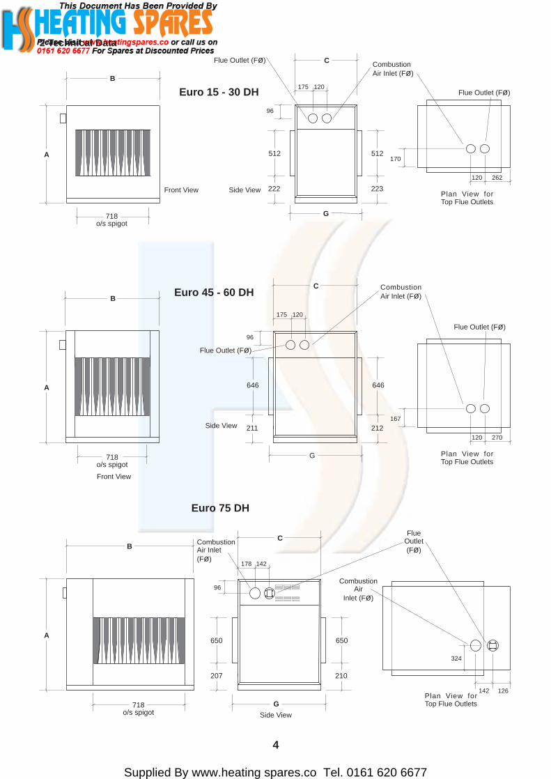
2 Technical Data
Euro 15 - 30 DH
Front View
B
A
G
C
Side View
Flue Outlet (Fø) CombustionAir Inlet (Fø)
175 120
96
Flue Outlet (Fø)
Plan View forTop Flue Outlets
120 262
170512512
207
718o/s spigot
Euro 75 DH
210
222 223
Euro 45 - 60 DH
Front View
B
A
718o/s spigot
C
646
Side View
Flue Outlet (Fø)
CombustionAir Inlet (Fø)
175 120
96
Flue Outlet (Fø)
Plan View forTop Flue Outlets
120 270
167
646
G
211 212

Supplied By www.heating spares.co Tel. 0161 620 6677
5
Euro 90 DH
B
1091o/s spigot
A
C
650
CombustionAir Inlet(Fø)
178 142
FlueOutlet(Fø)
99
Plan View forTop Flue Outlets
142
320
176
Side View
650
G
207 207
Front View
B
A
1460 (Euro 150 - 1760)o/s spigot
Euro 105 - 150 DH
C
646
Side View
CombustionAir Inlet (Fø)
178 142
96
646
G
211 212
FlueOutlet(Fø)
Plan View forTop Flue Outlets
142
324
176

Supplied By www.heating spares.co Tel. 0161 620 6677
6
Euro 15
Table 1a - Exhaust Fan Mounting Plate Inlet Diameters
Euro 22 Euro 30 Euro 45 Euro 52 Euro 60 Euro 75
34 42 50 60 70 90 N/ANote: Length, in mm, of oblong notch on plate side equals unit size.
Euro 90
N/A
595
795
Euro 15Euro 22Euro 30Euro 45Euro 52Euro 60Euro 75
F
Table 1Dimensions
875
1125
960
81
101
695
895
A B C G
1400Euro 90
m³/s Pa
Table 2 - Specifications
MODEL INPUT(Nett)
OUTPUT INPUT(Nett)
OUTPUT kg
kW kW
Euro 15 17.05 15.0 8.92 7.5 0.6048
Euro 22 25.57 22.5 13.39 11.25 0.9072
Euro 30 34.09 30.0 17.85 15.0 1.2096
Euro 45 51.14 45.0 26.78 22.5 1.8144
Euro 52 59.66 52.5 31.25 26.25 2.1168
Euro 60 68.18 60.0 35.71 30.0 2.4192
Euro 75 85.23 75.0 44.64 37.5 3.0240
33 100
67 100
53 100
138 140
143 140
152 140
155 166
HIGH FIRE LOW FIREAIR VOLUMEFOR 20°C rT@ High Fire
PRESSUREDROP
AT AIRFLOWFOR 20°C rT
WEIGHT
Euro 90 102.27 90.0 53.57 45.0 3.6288 237 200
1762Euro 105Euro 120
2059Euro 150
Euro 105 119.32 105.0 59.66 52.5 4.8384
Euro 120 136.36 120.0 68.18 60.0 6.0480
152 280
155 280
Euro 150 170.46 150.0 85.23 75.0 7.2576 237 332
MINIMUMAIRFLOW
REQUIREMENT
m³/s
0.4100
0.6000
1.8300
1.3000
1.4400
1.6600
2.0600
2.4800
2.9000
3.3100
4.1400
1083
Supplied By www.heating spares.co Tel. 0161 620 6677
InletINJECTORS
High FirePressure Burner Gas Rate29mb Pressure
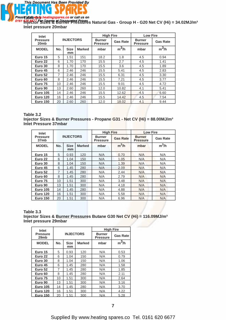
MODEL No. Size Marked mbar m3/h mm
Euro 15 5 0.93 120 N/A 0.53Euro 22 6 1.04 150 N/A 0.79Euro 30 8 1.04 150 N/A 1.06Euro 45 6 1.45 280 N/A 1.58Euro 52 7 1.45 280 N/A 1.85Euro 60 8 1.45 280 N/A 2.11Euro 75 10 1.51 300 N/A 2.64Euro 90 13 1.51 300 N/A 3.16Euro 105 14 1.45 280 N/A 3.70Euro 120 16 1.51 300 N/A 4.22Euro 150 20 1.51 300 N/A 5.28
Table 3.3Injector Sizes & Burner Pressures Butane G30 Net CV (Hi) = 116.09MJ/m³Inlet pressure 29mbar
7
Table 3.1Injector Sizes & Burner Pressures Natural Gas - Group H - G20 Net CV (Hi) = 34.02MJ/m³Inlet pressure 20mbar
InletINJECTORS
High Fire Low FirePressure Burner Gas Rate Burner Gas Rate20mb Pressure Pressure
MODEL No. Size Marked mbar m3/h mbar m3/h mm
Euro 15 5 1.51 151 18.2 1.8 4.5 0.94Euro 22 6 1.70 170 15.5 2.7 4.5 1.41Euro 30 8 1.70 170 15.5 3.6 4.5 1.89Euro 45 6 2.46 246 15.5 5.41 4.5 2.83Euro 52 7 2.46 246 15.5 6.31 4.5 3.30Euro 60 8 2.46 246 15.5 7.21 4.5 3.77Euro 75 10 2.46 246 15.5 9.01 4.5 4.72Euro 90 13 2.60 260 12.0 10.82 4.1 5.41Euro 105 14 2.46 246 15.5 12.62 4.5 6.60Euro 120 16 2.46 246 15.5 14.42 4.5 7.54Euro 150 20 2.60 260 12.0 18.02 4.1 9.44
Table 3.2Injector Sizes & Burner Pressures - Propane G31 - Net CV (Hi) = 88.00MJ/m³Inlet Pressure 37mbar
InletINJECTORS
High Fire Low FirePressure Burner Gas Rate Burner Gas Rate37mb Pressure Pressure
MODEL No. Size Marked mbar m3/h mbar m3/h mm
Euro 15 5 0.93 120 N/A 0.70 N/A N/AEuro 22 6 1.04 150 N/A 1.05 N/A N/AEuro 30 8 1.04 150 N/A 1.39 N/A N/AEuro 45 6 1.45 280 N/A 2.09 N/A N/AEuro 52 7 1.45 280 N/A 2.44 N/A N/AEuro 60 8 1.45 280 N/A 2.79 N/A N/AEuro 75 10 1.51 300 N/A 3.48 N/A N/AEuro 90 13 1.51 300 N/A 4.18 N/A N/AEuro 105 14 1.45 280 N/A 4.88 N/A N/AEuro 120 16 1.51 300 N/A 5.58 N/A N/AEuro 150 20 1.51 300 N/A 6.96 N/A N/A

Supplied By www.heating spares.co Tel. 0161 620 6677
Combustion airinlet grille
8
3. General Requirements
3.1 Related DocumentsThe installation of the air heater(s) must be in accordancewith the rules in force and the relevant requirements of theGas Safety Regulations, Building Regulations and the I.E.E.Regulations for Electrical Installations.It should be in accordance also with any relevant requirementsof the local gas region, local authority and fire authority andthe relevant recommendations of the following documents.
3.2 Air Handling UnitThe air handling unit containing the air heater must permitthe provision of a satisfactory flue system and an adequateair supply. The location must also provide adequate spacefor servicing.
3.3 Flue SystemEuromatic units feature a closed combustion circuit and havean internal exhaust fan, mounted downstream of the heatexchanger, to both assist the evacuation of the products ofcombustion and to draw in air for combustion.The air heater must be connected to the flue system that isprovided by Powrmatic Ltd. Several configurations of flueand combustion air ducts are available as showndiagrammatically (See Figs 1a - 1d).
3.4 Air SupplyHeaters not fitted with the concentric terminal and fluearrangement must have provision for the supply of combustionair. This air may be admitted through suitable grilles in theair handler casing into a space that connects directly withthe combustion air entry socket on the heater. This spacemust be sealed and seperate from the airflow sections of theair handler.
Fig. 1c - Horizontal - Top Outlet
Side View
TerminalLength(s)
AdjustableLength
Connector
90° Bend
Fig. 1b - Horizontal - Side Outlet
Plan View
TerminalLength(s)
AdjustableLength
Connector
Fig. 1d - Typical AHU Flue / Combustion Air
Plan View
Terminal
Length(s)
AdjustableLength
Connector
Access panelto heater
Side View
Terminal
Combustion airinlet grille
Euromatic Flue/Combustion Air Duct Options
Fig. 1a - Vertical - Top Outlet
Front View
Terminal
Length(s)
AdjustableLength
Connector
Flashing

Supplied By www.heating spares.co Tel. 0161 620 6677
3.5 Electrical SupplyWiring external to the air heater must be installed in accordancewith the I.E.E. Regulations for Electrical Installations and anylocal regulations which apply. Wiring should be completed inflexible conduit.All standard heaters are supplied by 230V - 1ph, 50Hz. Themethod of connection to the main electricity supply mustfacilitate the complete electrical isolation of the air heater(s).It must have a contact separation of at least 3mm in all poles.The method of connection should be provided adjacent to theair heater(s) in a readily accessible position.See the accompanying wiring diagram for the heater electricalconnectionsEuromatic units can also be supplied for 400V 3N, 50Hz.
4. Installation of Air Heater(s)
4.1 GeneralThe air heater must be installed into a purpose designed sectionof the air handling unit, the main air flow being ducted into,and away from the air heater via the duct spigots provided onthe heater. Full access must be maintained to the heater endpanel that provides service access to the burners and controls.Any combustible material adjacent to the air heater and theflue system must be so placed or shielded as to ensure that itstemperature does not exceed 65 °C.IMPORTANT:1. To facilitate removal of the burner tray there must be
no projection or fixture in front of the left hand accesspanel (when viewed from the front of the unit). Thedistance in which this is applicable is the same as thewidth of the heater.
4.2 Flue/Combustion Air Duct SystemAll models are provided with two sockets, either at the sideor the top of the unit as ordered, one for combustion air andthe other for the products of combustion (See Section 2 Page2). In all cases the flue outlet socket must be connected viathe provided flue system to outside air. The combustion airsocket need not be connected if it is required to take thecombustion air through grilles in the casing of the air handler.The normal maximum permitted length of flue system isi) for side outlet horizontal - 3mii) for top outlet vertical - 4miii) for top outlet horizontal (90° bends inc) - 3m.
The maximum permitted length of flue outlet only is doublethe above lengths. If an offset is required two sets of 45° bendsmay be used each set being equivalent to 0.5m of flue length.The minimum flue length (end of flue terminal to back, topor side of heater) shall not be less than 0.5m.All outer joints must be finished with the provided lockingbands. Application of a smear of silicon grease to the insideof sockets will assist in fitting components together. All flueand combustion air ducts must be supported independently ofthe air heater.
4.3 Installation of Flue System
4.3.1 Horizontal System - Standard (see Fig.1b and 1c)1. Locate the position of the flue terminal, allowing for a slightgradient down to the heater (2° - 3°) and cut a hole to suit.2. Fit the flue terminal, securing via the wall plate and weatherwith silicon sealant or similar.3. Extend the concentric flue to the heater using straight lengthsfitting an adjustable length prior to the connector, to facilitateflue disconnection for servicing. Fit connector to the heaterinlet/outlet spigots ensuring that the connector spigot that is
central to the concentric flue fits into the flue outlet socket.Extend the adjustable length to make the final connection. Donot exceed the maximum extended length so as to maintainjoint integrity.4. Ensure that internal silicon sealing rings are in place andthat all tubes are pushed fully home. Secure concentric lengthswith the locking band provided.5. If required the flue only can be terminated on the outsideof the air handling unit, using a single wall flue pipe connecteddirectly to the flue outlet socket of the heater and a grille fittedin the outer wall of the ahu to admit the combustion air (SeeFig 1d and Section 3.5).
4.3.2 Horizontal System - Internal Combustion Air1. Complete the run of flue sections from the terminal spigotto the flue outlet socket of the heater, ensuring that the internalsilicon sealing rings are in place.
4.3.3 Vertical System (see Fig.1a)1. Locate the position of the flue terminal cut a hole in theroof of the air handler to suit.2. Fit the flashing and the the flue terminal so that the loweredge of the outer case is over the top of the flashing. Weatherwith silicon sealant or similar.3. Extend the concentric flue to the heater using straight lengthsfitting an adjustable length prior to the connector, to facilitateflue disconnection for servicing. Fit connector to the heaterinlet/outlet spigots ensuring that the connector spigot that iscentral to the concentric flue fits into the flue outlet socket.Extend the adjustable length to make the final connection. Donot exceed the maximum extended length so as to maintainjoint integrity.4. Ensure that internal silicon sealing rings are in place andthat all tubes are pushed fully home. Secure concentric lengthswith the locking band provided.
4.4 Gas ConnectionTo facilitate removal of the burner tray for servicing purposesa servicing valve and downstream union must be fitted at theinlet to the air heater. The gas supply to the air heater mustbe completed in solid pipework and be adequately supported.WarningWhen completing the final gas connection to the heater donot place undue strain on the gas pipework of the heater.
4.5 Electrical ConnectionsAll units are fully prewired and only require final connectionsfor the incoming mains supply, completion of the controlcircuit and provision of a 0-10V modulation/burner ON/OFFcontrol signal. The main electrical supply must be run to apoint adjacent to the heater and be suitably terminated toprovide an isolation point that will prevent remote activationof the unit during servicing. The length of the conductorsbetween the cord anchorage and the terminals must be suchthat the current carrying conductors become taut before theearth conductor if the cable or cord slips out of the cordanchorage. All external controls must be of an approved type.
Euro DH models must be electrically interlocked to the airmovement system so that should this fail the heater will beswitched off.If required the main air fan can be contolled by the heater. Aconnection from heater terminal No 5 can be made to one sideof the fan motor contactor coil, the other side of the coil beingconnected to Neutral. Under no circumstances must the fanmotor electrical supply be taken direct from the internal wiringof the Euromatic heater.
9
Supplied By www.heating spares.co Tel. 0161 620 6677
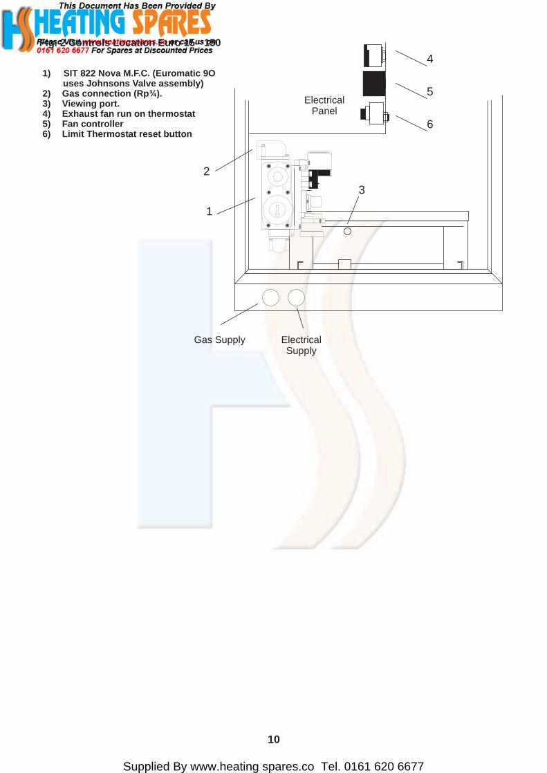
1) SIT 822 Nova M.F.C. (Euromatic 9O uses Johnsons Valve assembly)2) Gas connection (Rp¾).3) Viewing port.4) Exhaust fan run on thermostat5) Fan controller6) Limit Thermostat reset button
Fig. 2 Controls Location Euro 15 - 150
2
1
3
6
5
4
ElectricalPanel
Gas Supply ElectricalSupply
10
Supplied By www.heating spares.co Tel. 0161 620 6677
11
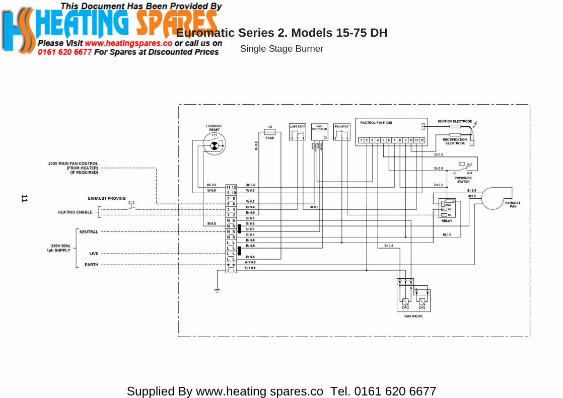
Euromatic Series 2. Models 15-75 DHSingle Stage Burner

Supplied By www.heating spares.co Tel. 0161 620 6677
12
Euromatic Series 2. Models 15-75 DHHi / Lo Burner
Supplied By www.heating spares.co Tel. 0161 620 6677
13
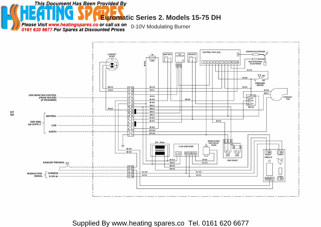
Euromatic Series 2. Models 15-75 DH0-10V Modulating Burner
Supplied By www.heating spares.co Tel. 0161 620 6677
14
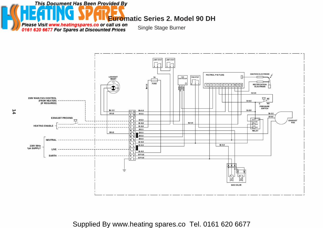
Euromatic Series 2. Model 90 DHSingle Stage Burner
Supplied By www.heating spares.co Tel. 0161 620 6677
15
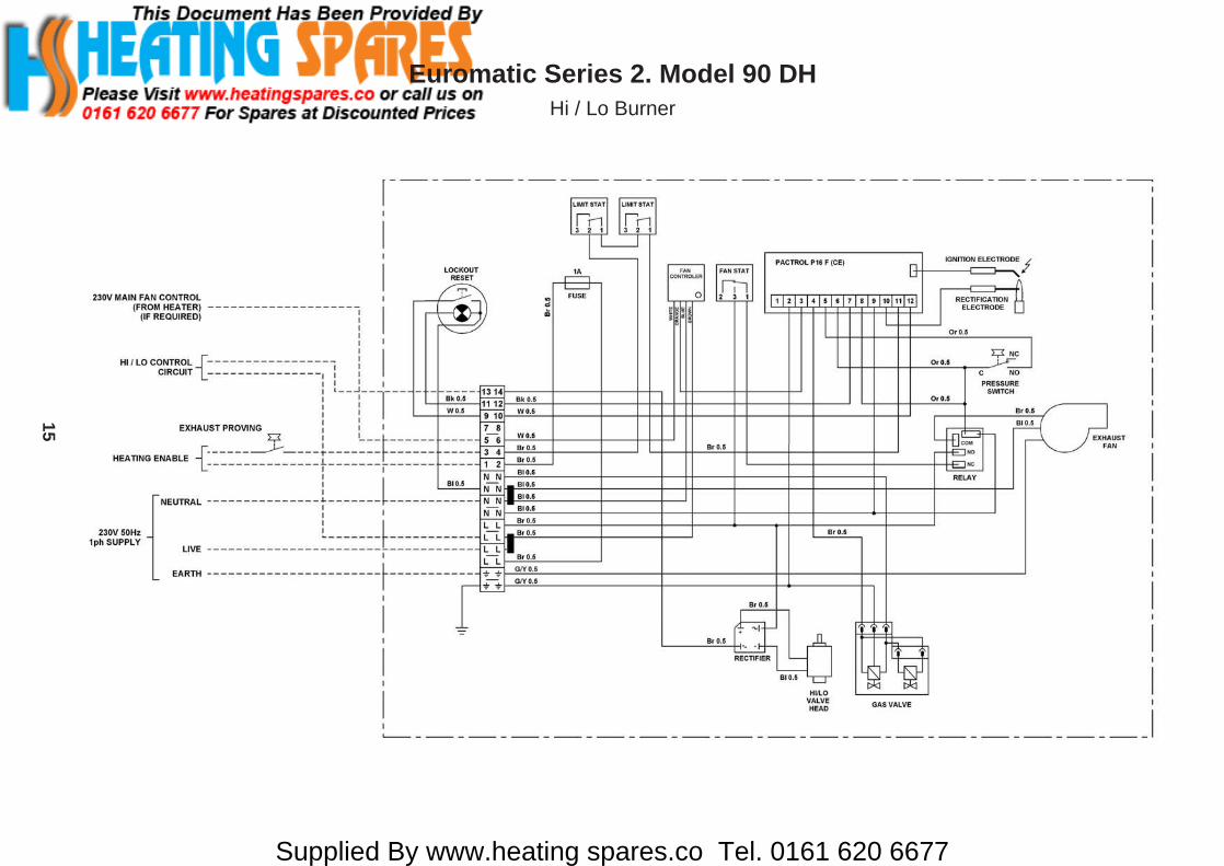
Euromatic Series 2. Model 90 DHHi / Lo Burner
Supplied By www.heating spares.co Tel. 0161 620 6677
16
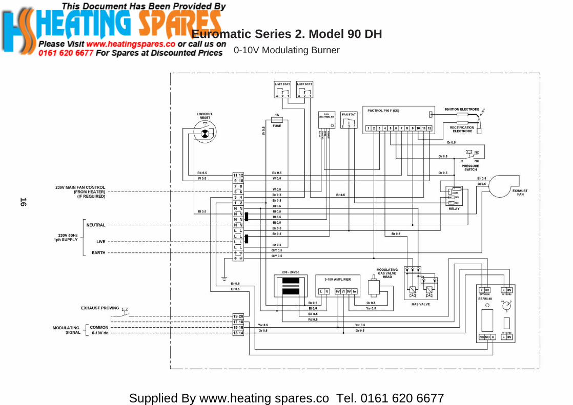
Euromatic Series 2. Model 90 DH0-10V Modulating Burner
Supplied By www.heating spares.co Tel. 0161 620 6677
17
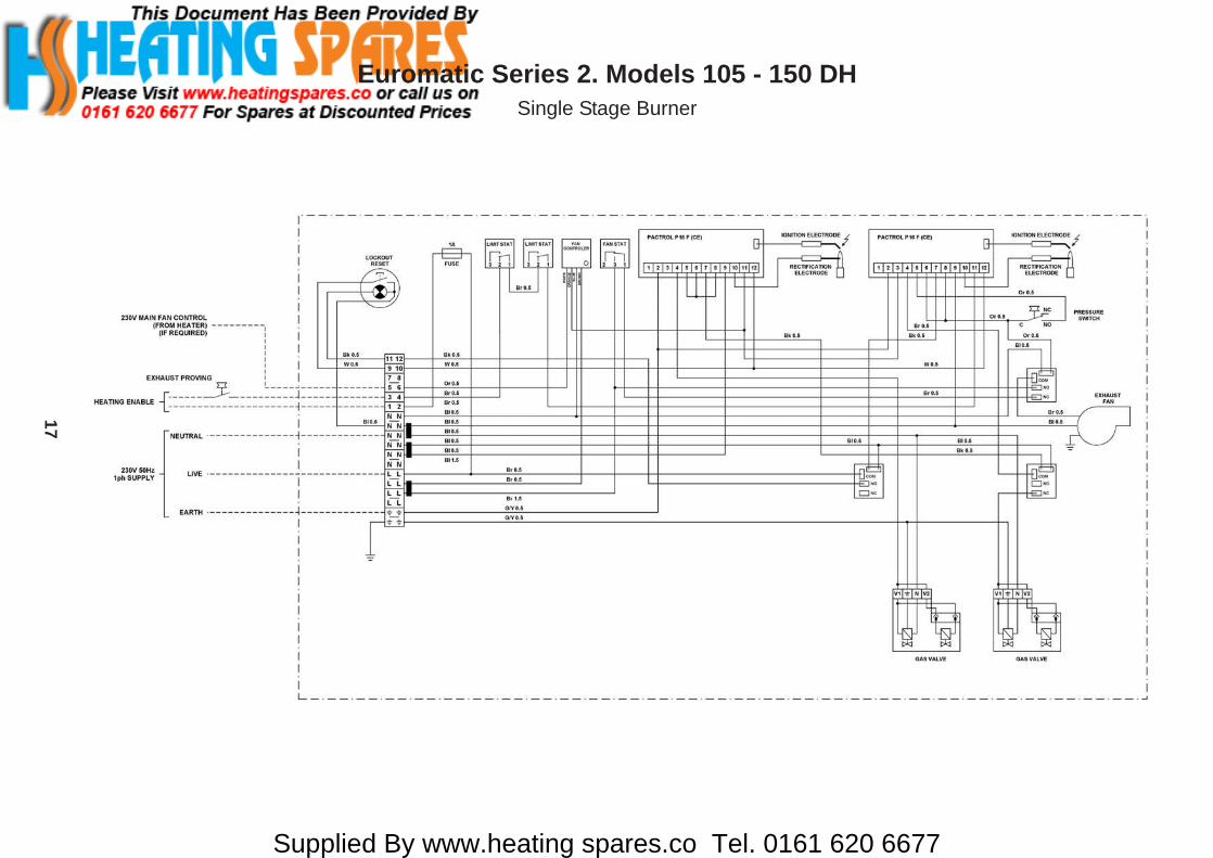
Euromatic Series 2. Models 105 - 150 DHSingle Stage Burner

Supplied By www.heating spares.co Tel. 0161 620 6677
18
Euromatic Series 2. Models 105 - 150 DHHi / Lo Burner
Supplied By www.heating spares.co Tel. 0161 620 6677
19
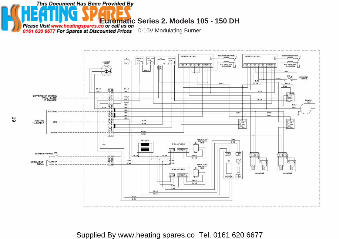
Euromatic Series 2. Models 105 - 150 DH0-10V Modulating Burner

Supplied By www.heating spares.co Tel. 0161 620 6677
20
Euromatic Series 2. Models 15-60Airflow Resistance
Euro 15 DH
0
50
100
150
200
250
300
350
0.25 0.50 0.75 1.00 1.25 1.50 1.75 2.00Airflow - (m³/s)
Pre
ssur
e D
rop
- (P
a)
Euro 22 DH
Airflow - (m³/s)
Pre
ssur
e D
rop
- (P
a)
0
50
100
150
200
250
0.25 0.50 0.75 1.00 1.25 1.50 1.75 2.00 2.25 2.50
Euro 30 DH
Airflow - (m³/s)
Pre
ssur
e D
rop
- (P
a)
0
50
100
150
200
250
300
0.25 0.50 0.75 1.00 1.25 1.50 1.75 2.00 2.25 2.50
Euro 45 DH
Airflow - (m³/s)
Pre
ssur
e D
rop
- (P
a)
0
50
100
150
200
250
0.25 0.50 0.75 1.00 1.25 1.50 1.75 2.00 2.25 2.50
Euro 52 DH
Airflow - (m³/s)
Pre
ssur
e D
rop
- (P
a)
0
50
100
150
200
250
300
0.25 0.50 0.75 1.00 1.25 1.50 1.75 2.00
0
20
40
60
80
100
120
140
160
180
0.25 0.50 0.75 1.00 1.25 1.50 1.75 2.00 2.25 2.50 2.75
Euro 60 DH
Airflow - (m³/s)
Pre
ssur
e D
rop
- (P
a)

Supplied By www.heating spares.co Tel. 0161 620 6677
21
Euromatic Series 2. Models 75-150Airflow Resistance
0
20
40
60
80
100
120
140
0.25 0.50 0.75 1.00 1.25 1.50 1.75 2.00 2.25 2.50 2.75
Euro 75 DH
Airflow - (m³/s)
Pre
ssur
e D
rop
- (P
a)
0
20
40
60
80
100
120
140
160
0.50 1.00 1.50 2.00 2.50 3.00
Euro 90 DH
Airflow - (m³/s)
Pre
ssur
e D
rop
- (P
a)
Euro 105 DH
Airflow - (m³/s)
Pre
ssur
e D
rop
- (P
a)
0
20
40
60
80
100
120
140
160
0.50 1.00 1.50 2.00 2.50 3.00 3.50 4.00 4.50 5.00
Euro 120 DH
Airflow - (m³/s)
Pre
ssur
e D
rop
- (P
a)
0
20
40
60
80
100
120
0.50 1.00 1.50 2.00 2.50 3.00 3.50 4.00 4.50 5.00
Euro 150 DH
Airflow - (m³/s)
Pre
ssur
e D
rop
- (P
a)
0
50
100
150
200
250
0.50 1.00 1.50 2.00 2.50 3.00 3.50 4.00 4.50 5.00
Supplied By www.heating spares.co Tel. 0161 620 667722
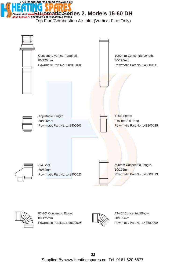
Concentric Vertical Terminal.80/125mmPowrmatic Part No. 148800001
Adjustable Length.80/125mmPowrmatic Part No. 148800003
Tube. 80mmFits into Ski Boot)Powrmatic Part No. 148800025
Ski Boot.80/80mmPowrmatic Part No. 148800023
500mm Concentric Length.80/125mmPowrmatic Part No. 148800013
1000mm Concentric Length.80/125mmPowrmatic Part No. 148800011
87-90º Concentric Elbow.80/125mmPowrmatic Part No. 148800005
43-45º Concentric Elbow.80/125mmPowrmatic Part No. 148800009
Euromatic Series 2. Models 15-60 DHTop Flue/Combustion Air Inlet (Vertical Flue Only)
Supplied By www.heating spares.co Tel. 0161 620 667723
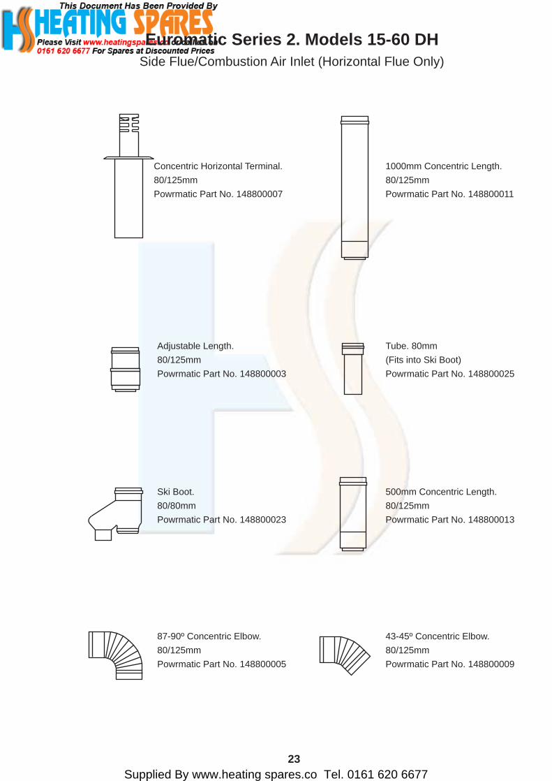
Concentric Horizontal Terminal.80/125mmPowrmatic Part No. 148800007
Adjustable Length.80/125mmPowrmatic Part No. 148800003
Tube. 80mm(Fits into Ski Boot)Powrmatic Part No. 148800025
Ski Boot.80/80mmPowrmatic Part No. 148800023
500mm Concentric Length.80/125mmPowrmatic Part No. 148800013
1000mm Concentric Length.80/125mmPowrmatic Part No. 148800011
87-90º Concentric Elbow.80/125mmPowrmatic Part No. 148800005
43-45º Concentric Elbow.80/125mmPowrmatic Part No. 148800009
Euromatic Series 2. Models 15-60 DHSide Flue/Combustion Air Inlet (Horizontal Flue Only)
Supplied By www.heating spares.co Tel. 0161 620 667724
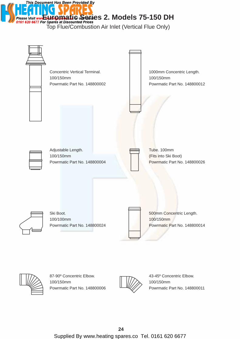
Concentric Vertical Terminal.100/150mmPowrmatic Part No. 148800002
Euromatic Series 2. Models 75-150 DHTop Flue/Combustion Air Inlet (Vertical Flue Only)
Adjustable Length.100/150mmPowrmatic Part No. 148800004
Tube. 100mm(Fits into Ski Boot)Powrmatic Part No. 148800026
Ski Boot.100/100mmPowrmatic Part No. 148800024
500mm Concentric Length.100/150mmPowrmatic Part No. 148800014
1000mm Concentric Length.100/150mmPowrmatic Part No. 148800012
87-90º Concentric Elbow.100/150mmPowrmatic Part No. 148800006
43-45º Concentric Elbow.100/150mmPowrmatic Part No. 148800011

Supplied By www.heating spares.co Tel. 0161 620 667725
Concentric Horizontal Terminal.100/150mmPowrmatic Part No. 148800008
Adjustable Length.100/150mmPowrmatic Part No. 148800004
Tube. 100mm(Fits into Ski Boot)Powrmatic Part No. 148800026
Ski Boot.100/100mmPowrmatic Part No. 148800024
500mm Concentric Length.100/150mmPowrmatic Part No. 148800014
1000mm Concentric Length.100/150mmPowrmatic Part No. 148800012
87-90º Concentric Elbow.100/150mmPowrmatic Part No. 148800006
43-45º Concentric Elbow.100/150mmPowrmatic Part No. 148800011
Euromatic Series 2. Models 75-150 DHSide Flue/Combustion Air Inlet (Horizontal Flue Only)

Supplied By www.heating spares.co Tel. 0161 620 667726
1000mm Flue Length.100mm dia.Powrmatic Part No. 148800026
1000mm Flue Length.80mm dia.Powrmatic Part No. 148800025
Euromatic Exhaust Guard.Powrmatic Part No. 146600021
Euromatic Series 2. Models 15-150 DHStandard Parts

Supplied By www.heating spares.co Tel. 0161 620 6677
Every effort is made to ensure accuracy at time of going to press. However as part of our policy of continual product improvement, we reserve the right to alter specifications without prior notice.
Powrmatic LtdHEATING DIVISIONWinterhay Lane
Ilminster, Somerset TA19 9PQTel: 01460 53535 Fax: 01460 52341
FM414Industrial and Commercial
Air Heaters; Air MovingEquipment; Flue and
Chimneys; Natural, Smokeand Heat Ventilators;Powered Supply and
Extract Fans and Systems.
BSI Registered Firm
RE G I S T E R ED
BSI