europrofi 3 euromatic
TRANSCRIPT

Operator's Manual+ INSTRUCTIONS FOR PRODUCT DELIVERY . . . Page 3
Ihre / Your / Votre • Masch.Nr. • Fgst.Ident.Nr.
GBNr. 99 544.GB.80D.0
EUROPROFI 3 Euromatic(Type 544)
ALLG./BA SEITE 2 / 9300-GB
Important information concerning Product Liability.According to the laws governing product liability, the manufacturer and dealer areobliged to hand the operating manual to the customer at the time of sale, and toinstruct them in the recommended operating, safety, and maintenance regulations.Confirmation is necessary to prove that the machine and operatingmanual have been handed over accordingly.For this purpose, document A is to be signed and sent to Pöttinger,document B remains with the dealer supplying the machine, and thecustomer receives document C.
In accordance with the laws of product liability, every farmer is an entrepreneur.
According to the laws of product liability, property damage is damage caused by amachine and not to it. An excess of Euro 500 is provided for such a liabilioty.
In accordance with the laws of product liability, entrepreneurial property damagesare excluded from the liability.
Attention! Should the customer resell the machine at a later date, the operatingmanual must be given to the new owner who must then be instructed in therecommended regulations referred to herein.
GB
Dear FarmerYou have just made an excellent choice. Naturally weare very happy and wish to congratulate you forhaving chosen Pöttinger. As your agricultural partner,we offer you quality and efficiency combined withreliable servicing.In order to assess the spare-parts demand for ouragricultural machines and to take these demandsinto consideration when developing new machines,we would ask you to provide us with some details.Furthermore, we will also be able to inform you of newdevelopments.

Dokument D
GB-0100 Dokum D Anhänger - 3
ALOIS PÖTTINGER Maschinenfabrik GmbHA-4710 GrieskirchenTel. (07248) 600 -0Telefax (07248) 600-511
GEBR. PÖTTINGER GMBHD-86899 Landsberg/Lech, Spöttinger-Straße 24Telefon (0 81 91) 92 99-111 / 112Telefax (0 81 91) 92 99-188
GEBR. PÖTTINGER GMBHServicezentrumD-86899 Landsberg/Lech, Spöttinger-Straße 24Telefon (0 81 91) 92 99-130 / 231Telefax (0 81 91) 59 656
❑ Machine checked according to delivery note. Allattached parts removed. All safety equipment, driveshaft and operating devices at hand.
❑ Operation and maintenance of machine and/orimplement according to operating instructionsexplained to the customer.
❑ Tyres checked re. correct pressure.
❑ Wheel nuts checked re. tightness.
❑ Drive shaft cut to correct lenght.
❑ Correct power-take-off speed indicated.
❑ Mechanical functions (opening of rear gate, pivotingof cutting mechanism out/in, etc.) demonstrated andexplained.
❑ Removing and mounting of knives explained.
❑ Electrical connection to tractor established andchecked re. correct supply (54 g connected). Notereferences in operating manual.
Please check. X
According to the product liability please check the above mentioned items.
INSTRUCTIONS FORPRODUCT DELIVERY
GB
❑ Fitting to tractor carried out: hight of drawbar adjusted,brake cable installed, hand brake lever assembled intractor cabin.
❑ Function of electrical installation checked andexplained.
❑ Hydraulic connection to tractor established and checkedre. correct supply.
❑ Hydraulic functions (drawbar, opening of rear gate, etc.)demonstrated and explained.
❑ Handbrake and operating brake tested re. function.
❑ Trial run carried out and no defects found.
❑ Functions explained during trial run.
❑ Automatic on/off switch of loading mechanism checked.
❑ Pivoting in transporting and operating positionexplained.
❑ Information given re. optional extras.
❑ Absolute need to read the operating manual indicated.
In order to prove that the machine and the operating manual have been properly delivered, a confirmation is necessary.For this purpose please do the following:- sign the document A and send it to the company Pöttinger
(in case of Landsberg equipment: to the company Landsberg)- document B stays with the specialist factory delivering the machine.- document C stays with the customer.
GBTABLE OF CONTENTS
- 4 -544.GB.809.0 INHALT
Table of contentsMeaning of warning signs .................................................. 5
Recommendations for work safety ..................................... 5
General safety tips for using the trailer .............................. 6
Travelling on roads ............................................................. 6
PUTTING INTO OPERATION ............................................ 6
Before starting work ........................................................... 6
Checking before operation ................................................. 6
Hydraulic connection .......................................................... 7
Connecting hydraulic lines ................................................. 7
Power supply ..................................................................... 8
To make the connection to the tractor ................................ 8
Installation of control panel ................................................ 8
Adjustment of drawbar to tractor’s towing coupler ............. 9
Raising the jack stand by hand .......................................... 9
Important hint! .................................................................... 9
Height (M) = 460 mm ....................................................... 10
Setting of Pick-up pivoting area (Height (M) = 460 mm) .................................................... 10
Adaption to drive shaft ..................................................... 10
Garaging the trailer .......................................................... 10
Electro-Hydraulics .............................................................11
Control panel "D" ............................................................... 11
Control panel "L" ............................................................... 11
Explanation of control panel function ............................... 12
Operation using buttons (57) above the cutter bar .......... 14
Advice in case of press channel blockage ....................... 14
Automatic loading ............................................................ 15
Disruptions and remedies to power failure ....................... 16
Scraper floor drive - Adjustment possibilities ................... 17
Removal of regulating rollers ........................................... 18
Scraper floor switch ......................................................... 18
Installing an oil pressure switch ....................................... 18
Starting the loading process ............................................ 19
To observe during the loading process! ........................... 19
Tailgate ............................................................................. 20
Unloading the trailer ......................................................... 21
Shut-off clutch (NS) .......................................................... 21
Road travel ....................................................................... 21
Assembling the top frame section .................................... 22
Cutting Unit ...................................................................... 24
Important! Lock the cutting beam with bolts .................... 24
Swinging the cutter beam ................................................ 25
Adjusting the cutter beam ................................................ 26
Adjusting the cutters ........................................................ 26
Checking the clearance from the blades to the press rotor ........ 27
Advice for general maintenance ...................................... 28
Opening the side protectors ............................................. 28
Cleaning of machine parts ............................................... 28
Brake adjustment ............................................................. 28
Hydraulic unit ................................................................... 29
Gas container ................................................................... 29
Maintenance .................................................................... 30
Adjusting measurement for end switch ............................ 32
Safeguarding the electrical unit ........................................ 32
Removing a stripper ......................................................... 33
Automatic Chain Lubrication 1) ........................................ 34
Changing the filter ............................................................ 34
Transmission .................................................................... 34
Wheels and tyres ............................................................. 35
Starting torque ................................................................. 35
Air pressure ...................................................................... 35
Tecnical data .................................................................... 40
Optional equipment .......................................................... 40
Defined use of the trailer .................................................. 41
Correct loading: ................................................................ 41
Supplement ...................................................................... 44
DRIVESHAFT .................................................................. 46
- 5 -AZB 9700-GB (544)
GBWARNING SIGNS
CE sign
The CE sign, which is affixed by the manufacturer, indicates outwardlythat this machine conforms to the engineering guideline regulations andthe other relevant EU guidelines.
EU Declaration of Conformity
By signing the EU Declaration of Conformity, the manufacturer declaresthat the machine being brought into service complies with all relevantsafety and health requirements.
495.151
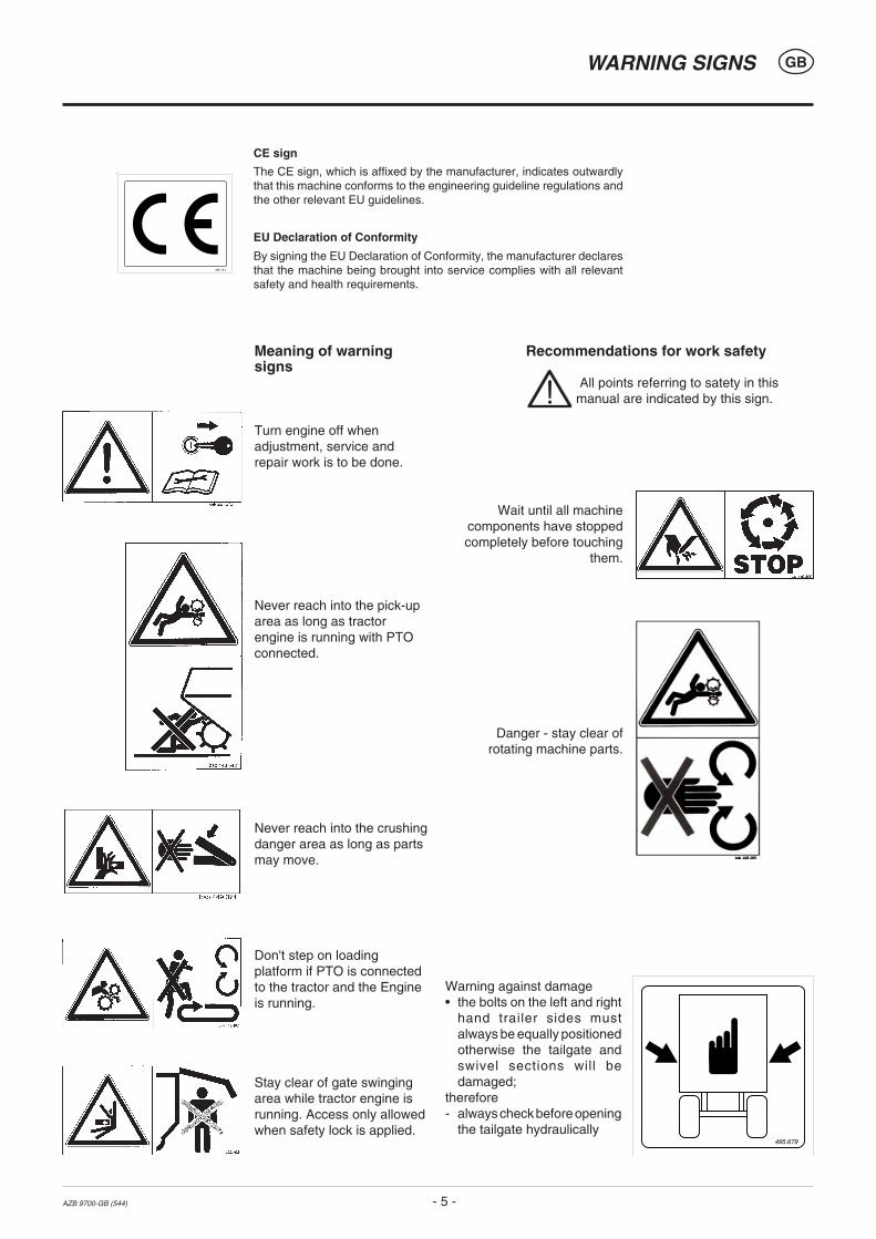
Meaning of warningsigns
Turn engine off whenadjustment, service andrepair work is to be done.
Never reach into the pick-uparea as long as tractorengine is running with PTOconnected.
Never reach into the crushingdanger area as long as partsmay move.
Don't step on loadingplatform if PTO is connectedto the tractor and the Engineis running.
Stay clear of gate swingingarea while tractor engine isrunning. Access only allowedwhen safety lock is applied.
Recommendations for work safety
All points referring to satety in thismanual are indicated by this sign.
Wait until all machinecomponents have stoppedcompletely before touching
them.
Danger - stay clear ofrotating machine parts.
495.679
Warning against damage• the bolts on the left and right
hand trailer sides mustalways be equally positionedotherwise the tailgate andswivel sections will bedamaged;
therefore- always check before opening
the tailgate hydraulically

Before starting worka. Before commencing work, the operator must be aware of
all operating devices and functions. The learning of theseis too late after having already commenced operation!
b. The vehicle is to be tested for traffic and operating safetybefore each operation.
c. The danger of being crushed or cut exists in the Pick-up,cutting unit, tailgate and upper extension areas. All personsmust be shown out of these areas before activating hydraulicequipment and turning on the drive.
d. Before driving the vehicle, the driver must ensure thatnobody will be endangered and that no obstructions arepresent. If the driver is unable to see and have an overallview of the roadway directly behind the trailer, he must beguided by somebody while reversing.
e. Observe the safety tips which are attached to the trailer. Anexplanation of what the individual graphic warning symbolsmean can be found on page 4.
f. Observe also the tips in the respective chapters and in thesupplement to this operating manual.
Checking before operationThe following tips should make the trailer's operationeasier for you. Detailled information for individualpoints can be found in the respective chapters in thisoperating manual.
1. Check that all safety equipment (coverings, casings, etc.)are in proper order and fitted in position on the trailer.
2. Grease the trailer in accordance with the lubrication chart.Check the gearing for tightness and the oil level.
3. Check that tyres have the correct air pressure.
4. Check that wheel nuts are sitting firmly.
5. Ensure the correct p.t.o.-r.p.m..
6. Make the electrical connections to the tractor and checkthat they are correct. Take note of the tips in the operatingmanual!
7. Carry out the following adaptions:
• Drawbar height
• Laying of brake cable
• Install hand brake lever in the tractor cabin.
8. Secure trailer using only the fixtures provided.
9. Cut drive shaft to the correct length and check the functionof the overload safety (see supplement).
10. Check the electronic unit function.
11. Connect hydraulic lines to tractor.
• Check hydraulic hoses for damage and wear.
• Ensure the correct connection.
12. All swivelling parts (tailgate, adjusting lever, etc.) must besecured against dangerous position changes.
13. Check parking brake and service brake functions.
General safety tips for using thetrailer
Tips for travelling with the trailerThe handling of the tractor is influenced by the trailercoupled to it.
• Danger of tipping exists when working on slopes.
• The driving must be adaptedto the corresponding terrainand ground conditions.
• The towing vehicle is to besufficiently equiped withweights at the front or at therear in order to guarantee thesteering and braking capacity(a minimum of 20% of thevehicle's tare weight on thefront axle).
• The transport of persons on the machine is not permitted.
Tips for coupling and uncoupling the trailer• Danger of injury exists when coupling the implement to the
tractor!
• As long as the tractor is moving backwards, do not stepbetween it and the trailer when coupling.
• Nobody is to stand between the tractor and trailer withoutthe vehicles being secured againstrolling with the parking brake and/orwheel chocks.
• Drive shaft connection ordisconnection is only to be undertakenwhen the motor has stopped.
Parking the implement• When the implement ist parked, either
remove the driveshaft and store it, orsecure it with a chain.
Do not use retaining chain (H) for this.
Only use the trailer according to regulations!Regulations for Use: See chapter "Technical Data".
• The trailer's load limits (permitted axle load, support load,total weight) may not be exceeded. The relevant detailsare located on the right side of the trailer.
• In addition, observe the power limits of the tractor beingused.
Travelling on roads• Observe the road rules.
• The tailgate must be closed when travelling on publicroads. Lighting devices must be fitted vertically to the road.
20%Kg
GB
- 6 -9500 GB INBETRIEBNAHME (511)
PUTTING INTO OPERATION
ERSTANBAU 9800-GB (544)
FIRST-TIME CONNECTION TO TRACTOR GB
- 7 -
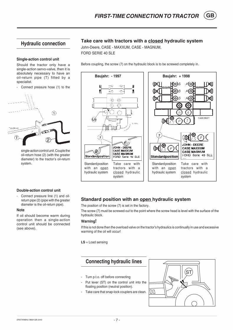
ST
Take care with tractors with a closed hydraulic systemJohn-Deere, CASE - MAXXUM, CASE - MAGNUM,
FORD SERIE 40 SLE
Before coupling, the screw (7) on the hydraulic block is to be screwed completely in.
Standard position with an open hydraulic systemThe position of the screw (7) is set in the factory.
The screw (7) must be screwed out to the point where the screw head is level with the surface of thehydraulic block.
Warning!If this is not done then the overload valve on the tractor’s hydraulics is continually in use and excessivewarming of the oil will occur!
LS = Load sensing
Connecting hydraulic lines
- Turn p.t.o. off before connecting
- Put lever (ST) on the control unit into thefloating position (neutral position).
- Take care that snap-lock couplers are clean.
Hydraulic connection
Single-action control unitShould the tractor only have asingle-action servo-valve, then it isabsolutely necessary to have anoil-return pipe (T) fitted by aspecialist.
- Connect pressure hose (1) to the
single-action control unit. Couple theoil-return hose (2) (with the greaterdiameter) to the tractor’s oil-returnsystem.
Double-action control unit- Connect pressure line (1) and oil-
return pipe (2) (pipe with the greaterdiameter is the oil-return pipe).
NoteIf oil should become warm duringoperation then a single-actioncontrol unit should be connected(see above).
Baujahr: - 1997 Baujahr: + 1998
Take care withtractors with aclosed hydraulicsystem
Standard positionwith an openhydraulic system
Take care withtractors with aclosed hydraulicsystem
Standard positionwith an openhydraulic system
ERSTANBAU 9800-GB (544)
FIRST-TIME CONNECTION TO TRACTOR GB
- 8 -
12V=
11 9 3-POL
"15/30"
"31"
10
TD 52/97/12
86 86a 87
85 30
+
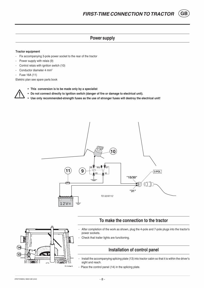
Power supply
Tractor equipment
- Fix accompanying 3-pole power socket to the rear of the tractor
- Power supply with relais (9)
- Control relais with ignition switch (10)
- Conductor diameter 4 mm2
- Fuse 16A (11)
Elektric plan see spare parts book
• This conversion is to be made only by a specialist
• Do not connect directly to ignition switch (danger of fire or damage to electrical unit).
• Use only recommended-strength fuses as the use of stronger fuses will destroy the electrical unit!
To make the connection to the tractor
- After completion of the work as shown, plug the 4-pole and 7-pole plugs into the tractor'spower sockets.
- Check that trailer lights are functioning.
Installation of control panel
- Install the accompanying splicing plate (13) into tractor cabin so that it is within the driver’ssight and reach.
- Place the control panel (14) in the splicing plate.

ERSTANBAU 9800-GB (544)
FIRST-TIME CONNECTION TO TRACTOR GB
- 9 -
Important hint!
Driveshaft overload safety (540 r.p.m. , 1000 r.p.m.) see page 12.
Adjustment of drawbar to tractor’s towing coupler
- Extend the drawbar coupling (A) so that there is sufficient gap between drive shaft anddrawbar of attached trailer, especially in the event of pivoting.
Raising the jack stand by hand
- Couple the trailer to tractor
- Take load off jackstand by using pivoting drawbar( see chapter “Explanation of control panelfunction”).
- Pull out locking bolt (1 ), swing jack stand up andlock again.
- Make sure bolt is properly locked in (1).

0400-GB DEICHSELEINSTELLUNG_544
GB
- 10 -
ADJUSTING DRAWBAR
Height (M) = 460 mmTo allow pick-up to work properly, the height (H ) of coupled trailer must be correctly set (pick-up pivoting area).
Note: Where the floor is uneven, reduce the measurement by 1 cm (M = 470 mm)
Setting of Pick-up pivoting area (Height (M) = 480 mm)
- Couple trailer to tractor - Both hydraulic cylinder pistons must be completely inserted.
Adjustment of both hydraulic cylinders must take place alternately
- Loosen lock nut (K) on the threaded spindle
- By twisting the cylinder piston (50), screw the threaded spindle in or out until the height (M) is achieved.
- Retighten lock nut (K)
Put into operationBefore putting the tractor into operation check vehicle safety (lights, brake unit, protective covering, .....).
Adaption to drive shaft
To shorten the drive shaft see supplement-B
Garaging the trailer
Attention!
Only garage an empty trailer on the jack stand and chock the wheels to prevent rolling.
• Park the trailer on firm, level ground.
If the ground is soft then the area where the jack stand is to stand must be appropriately increased using a suitable aid (e.g. wooden board).
- Raise the trailer a little using the pivoting drawbar .
- Pull out locking bolt (1), swing jack stand down and lock again.
- Make sure bolt (1) is properly locked in!
- Lower the trailer using the pivoting drawbar.
- HUncouple hydraulic- and electric lines and detach trailer.

ELEKTROHYDRAULIK 9900-GB (544)
ELECTRO-HYDRAULICS GB
- 11 -
Control panel "D"
This control panel is a standard fitting in trailers withregulating rollers.
• To load trailer, it is necessary to plug in control panel(14b). This mode of operation (ON) enables every switchfunction to be used.
• To unload trailer, control panel "D" can be plugged intosocket on tail gate (14a).
This mode of operation does not enable switch functionsfor the pick-up lift, pivoting drawbar and for swivelling thecutter bar to be used.
• We recommend the use of control panel "L"in addition to control panel "D".
Control panel "L" then remains in thetractor cabin during operation and controlpanel "D" on the tail gate.
Control panel "L"
This control panel is a standard fitting in trailerswithout regulating rollers.
• Depending on trailer equipment, the order of
the operating controls can differ slightly fromthe diagramm shown.
- Both "QB" switches are only available ontrailers with a cross belt.
- The "AUTO" switch are only available ontrailers with a automatic loading system.
.
The following operating manualapplies to trailers fitted with all addi-tional equipment.
Electro-Hydraulics
Safety tips
Please take particular care when the operating elements on the trailer and the tractor are to be used simultaneously by morethan one person. A conscientious arrangement should be made by those concerned before operation.
An example:Danger of injury arises if a person stands at the rear of the trailer and somebody in the tractor cabin activates a switching function(opening the tailgate, switch on the driving gear, ...).
- To unload the trailer push the switchback (A).
The switch is engaged and the scraperfloor runs backward (KR).
- To load the trailer, without using theautomatic load for example, push theswitch forward (B).
The scraper floor runs backward (KR)as long as the switch is kept in thisposition.
- Push switch down (B).
The scraper floor runs forward (KV).
KB KV-KR
KV KR
ELEKTROHYDRAULIK 9900-GB (544)
ELECTRO-HYDRAULICS GB
- 12 -
ST
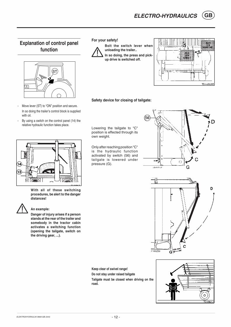
Explanation of control panelfunction
- Move lever (ST) to “ON” position and secure.
In so doing the trailer’s control block is suppliedwith oil.
- By using a switch on the control panel (14) therelative hydraulic function takes place.
With all of these switchingprocedures, be alert to the dangerdistances!
An example:
Danger of injury arises if a personstands at the rear of the trailer andsomebody in the tractor cabinactivates a switching function(opening the tailgate, switch onthe driving gear, ...).
For your safety!Bolt the switch lever whenunloading the trailer..
In so doing, the press and pick-up drive is switched off.
Safety device for closing of tailgate:
Lowering the tailgate to "C"position is effected through itsown weight.
Only after reaching position "C"is the hydraulic functionactivated by switch (56) andtailgate is lowered underpressure (G).
Keep clear of swivel range!
Do not stay under raised tailgate
Tailgate must be closed when driving on theroad.

ELEKTROHYDRAULIK 9900-GB (544)
ELECTRO-HYDRAULICS GB
- 13 -
Pivoting drawbar- Push switch up (A) and drawbar
is lowered.
- Push switch down (B) anddrawbar pivots up.
When driving on theroad the drawbarcylinder must bec o m p l e t e l yinserted.
Raising and lowering pick-up- Push switch down (B), pick-up
is lowered and remains infloating position.
- Push switch up (A), pick-up israised.
Unlocking the pressdrive switch levera u t o m a t i c a l l yswitches on thepress and pick-updrive (refers only totrailers withreguating fittings).
Loading without auto-matic-loader- To load the trailer, without using
the automatic load for example,push the switch back (A).
The scraper floor runs backward(KR) as long as the switch iskept in this position.
FULLIf the load pressesagainst the tailgateresp. on the lowerregulating roller, thescraper floor drive isturned off by means ofan switch and the lamp(FULL) on the controlpanel lights.
The lamp goes out onlywhen the pick-up israised.
The scraper floor drivecan be activated again
- when the tailgate isopened
- when the dispensingrollers are switched on
Trailer with regulating fittings- To unload the trailer push the
switch back (A).
The switch is engaged and thescraper floor runs backward (KR).
- Push the switch forward (B).
The scraper floor runs forward (KV).
The load pressure on the regulatingrollers is decreased.
- The scraper floor speed is adjustedusing the power regulator.
Dispensing rollers- When switch is pushed
up (A), then dispensingrollers are switched on.
- When switch is pushed
down (B), thendispensing rollers areswitched off.
Dry forage top frame- Lever to position "D"
- When switch is pushed up(A), then top frame folds up.
- When switch is pushed down (B),then top frame folds down.
Tailgate - Lever to position "R"
- Push switch up (A).
Tailgate swings up to "D" position.
The lamp above the switch remains alight aslong as the tailgate is open.
- Push switch down (B).
Tailgate is lowered and closed.
The lamp above the switch goes out whenthe tailgate is completely closed.
Safety device for closing oftailgate:
- see previous page
STOP - pressure switchThis switch acts as anEMERGENCY SHUT-OFFswitch.
When this switch is activated,the regulating rollers drive andscraper floor drive are switchedoff.
The control light intergrated intothe switch lights up, and theregulating rollers drive can onlybe switched on again when theSTOP - pressure switch isdepressed once again and thecontrol light goes out.
Note! The scraper floor push-button switch function isonly interrupted.
If the switch is in the Aposition, then after theSTOP - pressure switchshut-off function has beencancelled the scraper floorswitches itself on again.
KB KV-KR
KRKV
R
D
ELEKTROHYDRAULIK 9900-GB (544)
ELECTRO-HYDRAULICS GB
- 14 -
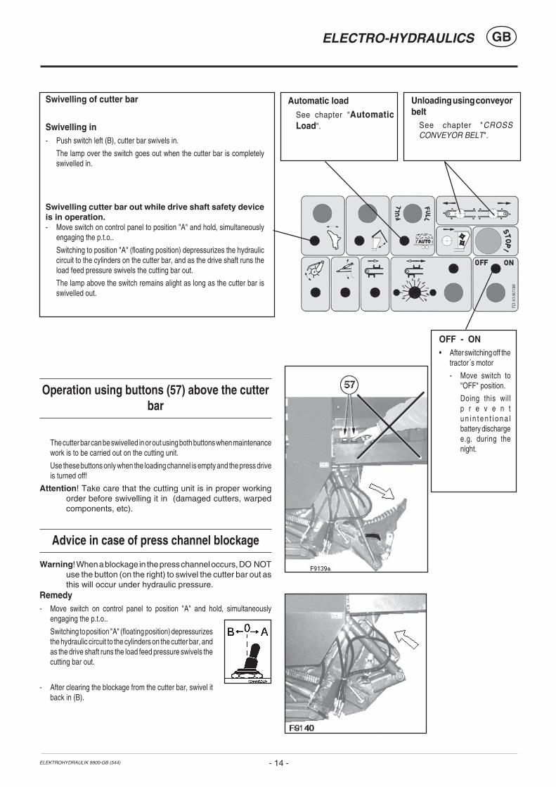
Swivelling of cutter bar
Swivelling in- Push switch left (B), cutter bar swivels in.
The lamp over the switch goes out when the cutter bar is completelyswivelled in.
Swivelling cutter bar out while drive shaft safety deviceis in operation.- Move switch on control panel to position "A" and hold, simultaneously
engaging the p.t.o..
Switching to position "A" (floating position) depressurizes the hydrauliccircuit to the cylinders on the cutter bar, and as the drive shaft runs theload feed pressure swivels the cutting bar out.
The lamp above the switch remains alight as long as the cutter bar isswivelled out.
Unloading using conveyorbelt
See chapter "CROSSCONVEYOR BELT".
Automatic loadSee chapter "AutomaticLoad".
Operation using buttons (57) above the cutterbar
The cutter bar can be swivelled in or out using both buttons when maintenancework is to be carried out on the cutting unit.
Use these buttons only when the loading channel is empty and the press driveis turned off!
Attention! Take care that the cutting unit is in proper workingorder before swivelling it in (damaged cutters, warpedcomponents, etc).
Advice in case of press channel blockage
Warning! When a blockage in the press channel occurs, DO NOTuse the button (on the right) to swivel the cutter bar out asthis will occur under hydraulic pressure.
Remedy- Move switch on control panel to position "A" and hold, simultaneously
engaging the p.t.o..
Switching to position "A" (floating position) depressurizesthe hydraulic circuit to the cylinders on the cutter bar, andas the drive shaft runs the load feed pressure swivels thecutting bar out.
- After clearing the blockage from the cutter bar, swivel itback in (B).
OFF - ON• After switching off the
tractor´s motor
- Move switch to"OFF" position.
Doing this willp r e v e n tu n i n t e n t i o n a lbattery dischargee.g. during thenight.

9700-GB LADEAUTOMATIK (544)
AUTOMATIC - LOADING GB
- 15 -
Automatic loading
• Push switch up (A)
- Automatic loader is activated and the switchremains in the up position.
• Switch in centre position (0)
- Automatic loader is turned off.
How the automatic loader works
When loading the trailer the area at the front is filled first.As soon as the load lifts the flap (58), the scraper floor drive is turned on by meansof the switch (59). The scraper floor will run until the flap (58) is lowered again.
When the load presses against the tailgate resp. on the lower regulating roller,the scraper floor is turned off automatically and the lamp (FULL) lights up on thecontrol panel.- Raise the pick-up, lamp (FULL) goes out.
The scraper floor drive can be activated again when the tailgate is opened.
NoteIf an additional function is required during the scraper floor operation, thenthe operation is interrupted automatically for the time period required.
Maintenance
- Disconnect the electrical connectionto the tractor when working on theelectrical unit.
- Change hydraulic oil in accordancewith tractor's operating manual.
- When welding on the trailer,disconnect all connections to thetractor and uncouple the trailer.
9700-GB ELEKT. STÖRUNGEN (544)
ELECTRO-HYDRAULICS GB
- 16 -
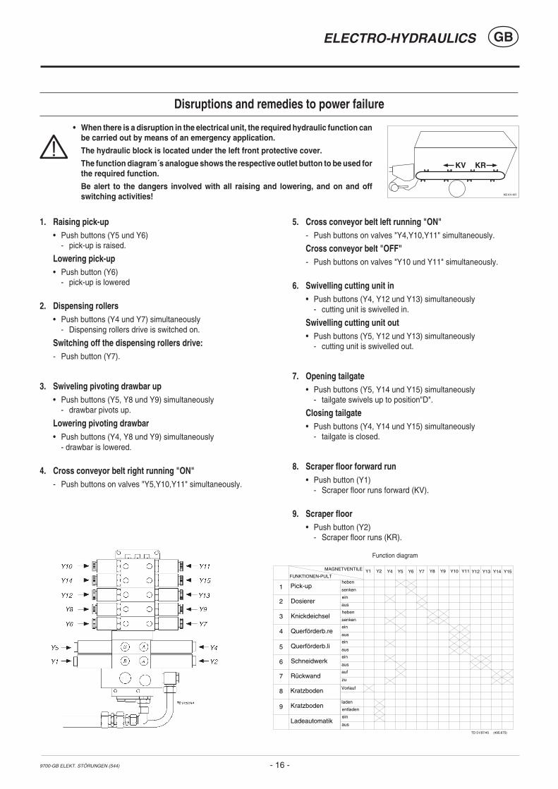
Disruptions and remedies to power failure
1. Raising pick-up• Push buttons (Y5 und Y6)
- pick-up is raised.
Lowering pick-up• Push button (Y6)
- pick-up is lowered
2. Dispensing rollers• Push buttons (Y4 und Y7) simultaneously
- Dispensing rollers drive is switched on.
Switching off the dispensing rollers drive:- Push button (Y7).
3. Swiveling pivoting drawbar up• Push buttons (Y5, Y8 und Y9) simultaneously
- drawbar pivots up.
Lowering pivoting drawbar• Push buttons (Y4, Y8 und Y9) simultaneously
- drawbar is lowered.
4. Cross conveyor belt right running "ON"- Push buttons on valves "Y5,Y10,Y11" simultaneously.
5. Cross conveyor belt left running "ON"- Push buttons on valves "Y4,Y10,Y11" simultaneously.
Cross conveyor belt "OFF"- Push buttons on valves "Y10 und Y11" simultaneously.
6. Swivelling cutting unit in• Push buttons (Y4, Y12 und Y13) simultaneously
- cutting unit is swivelled in.
Swivelling cutting unit out• Push buttons (Y5, Y12 und Y13) simultaneously
- cutting unit is swivelled out.
7. Opening tailgate• Push buttons (Y5, Y14 und Y15) simultaneously
- tailgate swivels up to position"D".
Closing tailgate• Push buttons (Y4, Y14 und Y15) simultaneously
- tailgate is closed.
8. Scraper floor forward run• Push button (Y1)
- Scraper floor runs forward (KV).
9. Scraper floor• Push button (Y2)
- Scraper floor runs (KR).
Y10 Y11
Querförderb.li
Querförderb.re
ein
ein
aus
aus
Pick-up
Knickdeichsel
Ladeautomatik
Kratzboden
Rückwand
Schneidwerk
MAGNETVENTILE Y2 Y4 Y5 Y6 Y8 Y15
Funktionsschaubild
heben
heben
ein
senken
senken
aus
auf
laden
ein
zu
entladen
aus
TD 51/97/45 (495.675)
Y9 Y12 Y13 Y14FUNKTIONEN-PULT
Y1
VorlaufKratzboden
Dosiererein
aus
Y7
1
2
3
4
5
6
7
8
9
Function diagram
KB KV-KR
KV KR
• When there is a disruption in the electrical unit, the required hydraulic function canbe carried out by means of an emergency application.
The hydraulic block is located under the left front protective cover.
The function diagram´s analogue shows the respective outlet button to be used forthe required function.
Be alert to the dangers involved with all raising and lowering, and on and offswitching activities!
GBSCRAPER FLOOR DRIVE - ADJUSTMENT POSSIBILITIES
- 17 -9800-GB KR-EINSTELLUNG (546)
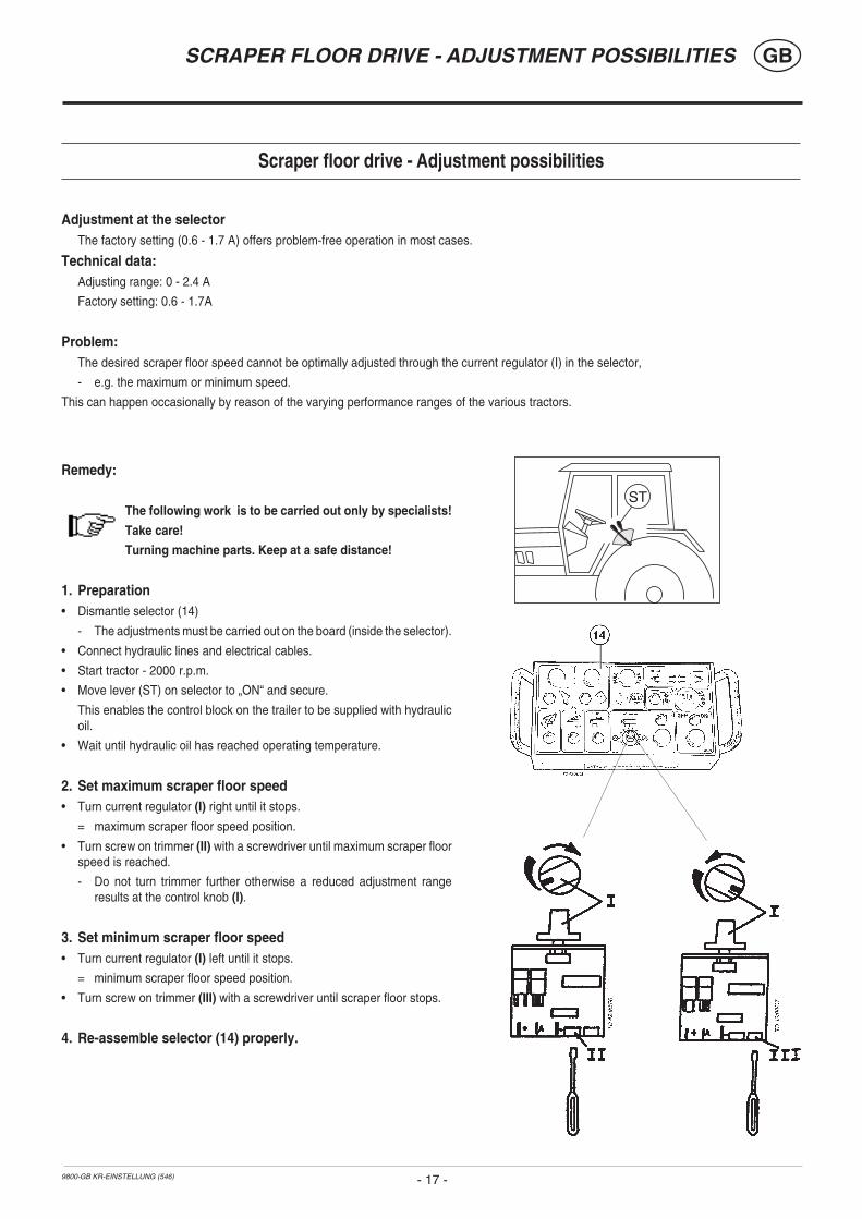
Scraper floor drive - Adjustment possibilities
Adjustment at the selectorThe factory setting (0.6 - 1.7 A) offers problem-free operation in most cases.
Technical data: Adjusting range: 0 - 2.4 A
Factory setting: 0.6 - 1.7A
Problem:The desired scraper floor speed cannot be optimally adjusted through the current regulator (I) in the selector,
- e.g. the maximum or minimum speed.
This can happen occasionally by reason of the varying performance ranges of the various tractors.
ST
Remedy:
The following work is to be carried out only by specialists!
Take care!
Turning machine parts. Keep at a safe distance!
1. Preparation• Dismantle selector (14)
- The adjustments must be carried out on the board (inside the selector).
• Connect hydraulic lines and electrical cables.
• Start tractor - 2000 r.p.m.
• Move lever (ST) on selector to „ON“ and secure.
This enables the control block on the trailer to be supplied with hydraulicoil.
• Wait until hydraulic oil has reached operating temperature.
2. Set maximum scraper floor speed• Turn current regulator (I) right until it stops.
= maximum scraper floor speed position.
• Turn screw on trimmer (II) with a screwdriver until maximum scraper floorspeed is reached.
- Do not turn trimmer further otherwise a reduced adjustment rangeresults at the control knob (I).
3. Set minimum scraper floor speed• Turn current regulator (I) left until it stops.
= minimum scraper floor speed position.
• Turn screw on trimmer (III) with a screwdriver until scraper floor stops.
4. Re-assemble selector (14) properly.
- 18 -(540) DOSIERER 9200 GB
GBREGULATING ROLLERS
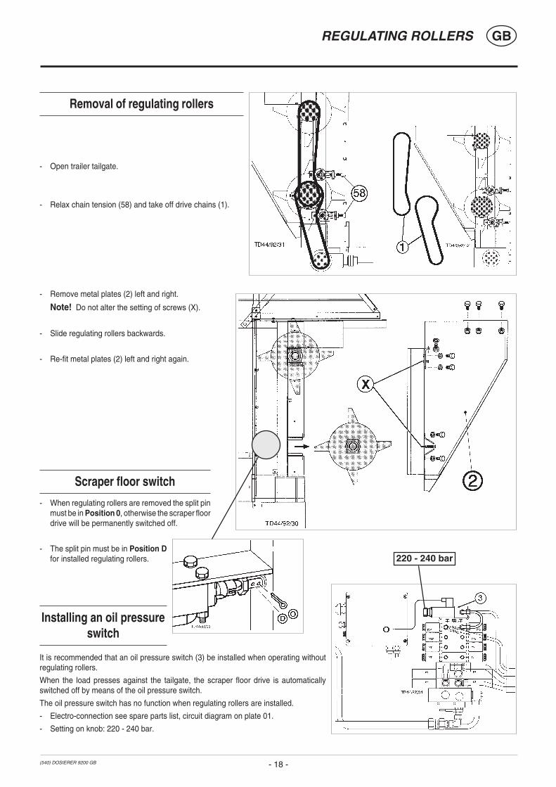
Removal of regulating rollers
- Open trailer tailgate.
- Relax chain tension (58) and take off drive chains (1).
- Remove metal plates (2) left and right.
Note! Do not alter the setting of screws (X).
- Slide regulating rollers backwards.
- Re-fit metal plates (2) left and right again.
Scraper floor switch
- When regulating rollers are removed the split pinmust be in Position 0, otherwise the scraper floordrive will be permanently switched off.
- The split pin must be in Position Dfor installed regulating rollers.
Installing an oil pressureswitch
It is recommended that an oil pressure switch (3) be installed when operating withoutregulating rollers.
When the load presses against the tailgate, the scraper floor drive is automaticallyswitched off by means of the oil pressure switch.
The oil pressure switch has no function when regulating rollers are installed.
- Electro-connection see spare parts list, circuit diagram on plate 01.
- Setting on knob: 220 - 240 bar.
220 - 240 bar

9700-GB BELADEN (544)
LOADING THE TRAILER
- 19 -
GB
Starting the loading process
1. Move control lever (43)for pick-up andconveyor drive to "ON"position.
2. Switch on tractor’sp.t.o..
3. Lower pick-up.
Take care! Doing thisautomatically switches on thePick-up and press drive.
When switch lever „43“ is inthe „OFF“ position then the Pick-up andpress will not be activated.
4. Move lever (ST) to “ON” position andsecure.In so doing the trailer’s control block issupplied with oil.
5. Observe p.t.o.-r.p.m.• Load using average p.t.o.-r.p.m. (400-450 rpm / 780-850 rpm) and high
running speed.
To observe during the loading process!
• Only raise pick-upwhen loadingchannel is empty.
• When drivingthrough curvesreduce motor r.p.m.
• When drivingthrough sharpcurves switch offp.t.o. and raise pick-up.
• Avoid uneven loads!Important because of possible drawbar overloading (seedetails on the drawbar concerning permitted support load).
• To ensure optimal filling of load space switch on scraperfloor briefly or activate the automatic loader (see chapter“ELECTRO HYDRAULICS”).
• Watch the trailer fill indicator (FULL).
• Observe the permitted axle load and total weight!
Finishing the loading process
1. Raise Pick-up.
Doing this automatically switches off the Pick-up and conveyor drive.
2. Move the switch lever „43“ to the „OFF“ position.
This position is for your safety. Doing this prevents the Pick-up andpress from being unintentionally activated, e.g. when lowering the Pick-up while the p.t.o. is running.
Safety tips:
• Turn off the drive motor and take off the drive shaftwhen carrying out all adjustment work.
• Faults in the Pick-up area are to be eliminated onlywhen the drive motor has been stopped.
Adjusting the pick-up1. Raise pick-up slightly and secure with adjusting struts (51), left
and right sides in same position.
2. Secure with linch pin.
High adjustment:with tall stubble andextremely unevenground.
Low Adjustment:with short green fodderand even ground.
Impact deflector adjustment (52)- In low position (T) for
small swaths and shortfodder.
- In high position (H) forhigh swaths.
Loading process in general
Important tips:• A transfer, which is located on the
drawbar, tells which p.t.o.-r.p.m. (450rpm/1000 rpm) your trailer is equipped for.
• Therefore take care that a drive shaft with the correct overloadsafety is used (see spare parts list), so that no unnecessarydamage is caused to the trailer through overloading.
1000 r.p.m.:Use a driveshaft with an overload safety of1500 Nm (153 kpm).
540 r.p.m.:Use a driveshaft with an overload safety of
2400 Nm (245 kpm).
• Always adapt driving speed to the surroundings.
• Avoid making sudden curves when driving through hills andvalleys, and when transversing slopes (danger of tipping).
• Cut short with less r.p.m., greater speed and bigger swaths.
Loading green fodder
- As a rule green fodder is collected in swaths.
- Cut swaths collected are always stalk heads.
- Set deflector (52) low position (T).
Loading dry fodder
- Correct dry fodder collection is in swaths.
- Set deflector (52) in the position (H).
ST
540 Upm 1000 Upm
GBTAILGATE
- 20 -9700-GB RÜCKWAND (544)
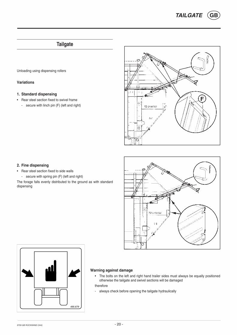
Tailgate
Unloading using dispensing rollers
Variations
1. Standard dispensing• Rear steel section fixed to swivel frame
- secure with linch pin (F) (left and right)
2. Fine dispensing• Rear steel section fixed to side walls
- secure with spring pin (F) (left and right)
The forage falls evenly distributed to the ground as with standarddispensing
495.679
Warning against damage• The bolts on the left and right hand trailer sides must always be equally positioned
otherwise the tailgate and swivel sections will be damaged
therefore
- always check before opening the tailgate hydraulically

(544) 9700-GB ENTLADEN
UNLOADING GB
- 21 -
Unloading the trailer
Unloading with regulating fittings- Open tailgate.
- Bolt switch lever (OFF).
In so doing, the press and pick-up drive is switched off.
- Switch on p.t.o. drive.
- Switch on regulating rollers drive.
- Switch on scraper floor drive (A).
- Adjust scraper floor speed using regulator (R).
Shut-off clutch (NS)
When regulating rollers are overloaded, e.g. when scraper floor speed istoo fast, the shut-off clutch cuts off the torque (= 1200 Nm).
- Switch off p.t.o. drive.
- Briefly switch on scraper floor forward run (B).
The scraper floor runs forward (KV). In so doing, the pressure on theregulating roller is decreased.
- Switch on p.t.o. drive again.
- Adjust scraper floor speed using regulator (R).
Unloading without regulating fittings- Open tailgate.
- Switch on scraper floor drive (A).
Push-button rear (32)- Scraper floor drive push-button
- When pressing push-button (32) it remains in position (C) and movingfloor drive is turned on.
- Pressing the push-button again turns off the moving floor drive (D).
General hintsSelecting another function in addition to the moving floor feedwill automatically interrupt the moving floor feed.
Finishing the unloading process- Switch off scraper floor drive (0).
- Close tailgate.
Road travel
Note! Only travel on roads with the tailgate closed.
R
KB KV-KR
KV KR

544 / AUFBAU UMLG / 9700-GB
GBASSEMBLY
- 22 -
Assembling the top frame section
• It is imperative that the machine stand horizontally and that two people carry out this modification.
• Danger of injury!
4. Remove both front hexagonal screws (SK)
5. Swing front side wall up
- left and right
- fix with linch pin (K)
1. Swing upper railing (3) up
2. Remove linch pin (K)
- left and right
3. Swing lower railing (3a) up
544 / AUFBAU UMLG / 9700-GB
GBASSEMBLY
- 23 -
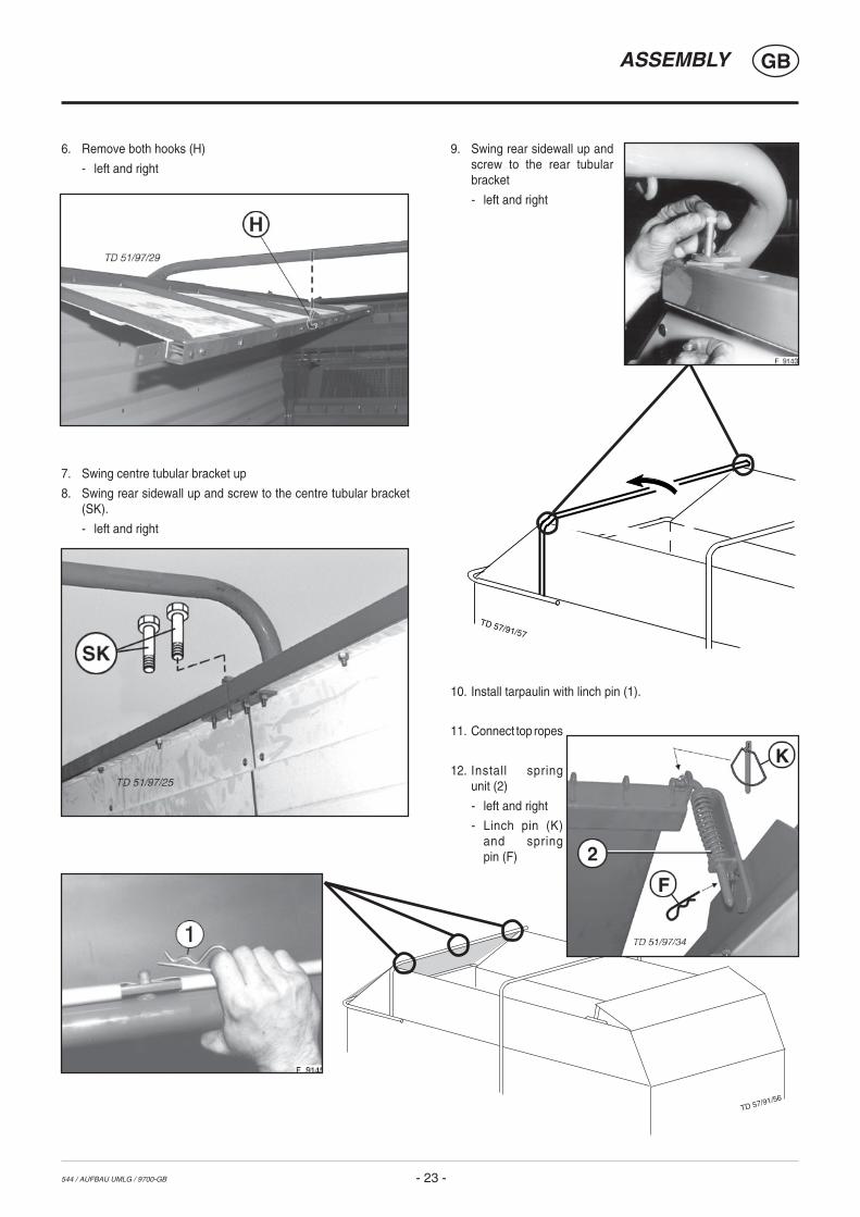
6. Remove both hooks (H)
- left and right
7. Swing centre tubular bracket up
8. Swing rear sidewall up and screw to the centre tubular bracket(SK).
- left and right
TD 57/91/57
9. Swing rear sidewall up andscrew to the rear tubularbracket
- left and right
10. Install tarpaulin with linch pin (1).
11. Connect top ropes
12. Install springunit (2)
- left and right
- Linch pin (K)and springpin (F)
TD 57/91/56

GBCUTTING UNIT, CUTTER BEAM
- 24 -0300-GB SCHNEIWERK_544
001-
01-0
3
E2
V
Cutting Unit
Important checks to be carried out on the cutter beambefore each operation
- left and right hand pins locked (E2)
- for wear on the cutters
- for dirt on the cutter overload fuse
- for adequate ground clearance (A)
* Vehicle must not be driven whilst cutter beam is in fullyextended position
General informationTo facilitate maintenance work on the cutting unit, the cutter beam canbe swung on to the left-hand side of the vehicle.
All cutters are then accessible:
- for grinding the cutters
- for installing or removing the cutters
- for cleaning
001-
01-1
1
E2
V
Important! Lock the cutting beam with bolts
* Position E2
- on the left and right side of the vehicle
- secure both bolts with forelock (V)
GBCUTTING UNIT, CUTTER BEAM
- 25 -0300-GB SCHNEIWERK_544
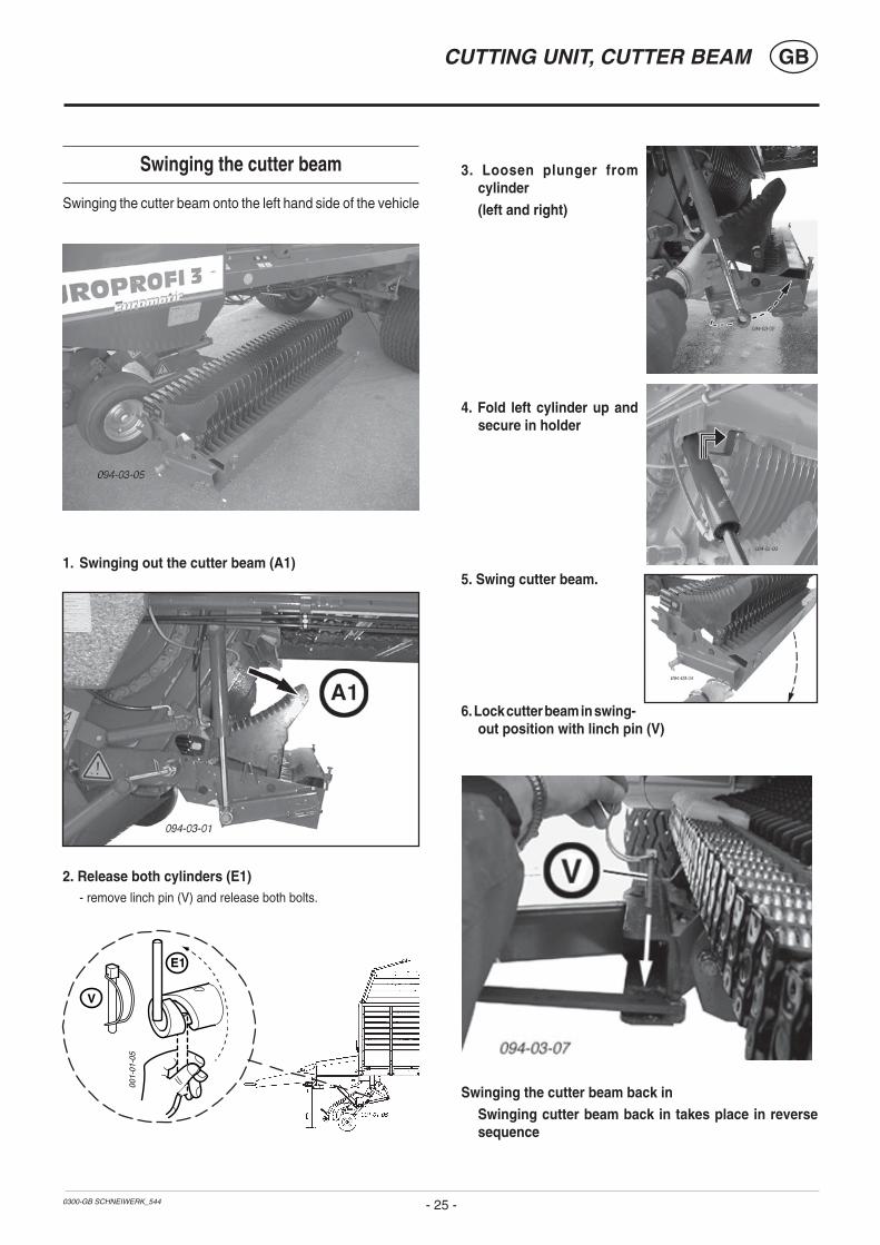
Swinging the cutter beam
Swinging the cutter beam onto the left hand side of the vehicle
1. Swinging out the cutter beam (A1)
001-
01-0
5
E1
V
3. Loosen plunger fromcylinder
(left and right)
4. Fold left cylinder up andsecure in holder
5. Swing cutter beam.
6. Lock cutter beam in swing-out position with linch pin (V)
Swinging the cutter beam back inSwinging cutter beam back in takes place in reversesequence
2. Release both cylinders (E1)- remove linch pin (V) and release both bolts.
GBCUTTING UNIT, CUTTER BEAM
- 26 -0300-GB SCHNEIWERK_544
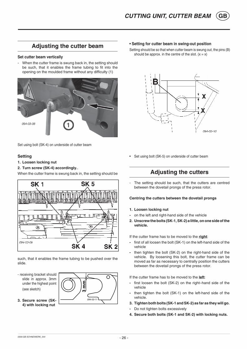
Adjusting the cutter beam
Set cutter beam vertically- When the cutter frame is swung back in, the setting should
be such, that it enables the frame tubing to fit into theopening on the moulded frame without any difficulty (1)
Set using bolt (SK-4) on underside of cutter beam
Setting1. Loosen locking nut
2. Turn screw (SK-4) accordingly..
When the cutter frame is swung back in, the setting should be
such, that it enables the frame tubing to be pushed over theslide.
- receiving bracket shouldslide in approx. 3mmunder the highest point
(see sketch)
3. Secure screw (SK-4) with locking nut
Adjusting the cutters
- The setting should be such, that the cutters are centredbetween the dovetail prongs of the press rotor.
Centring the cutters between the dovetail prongs
1. Loosen locking nut
- on the left and right-hand side of the vehicle
2. Unscrew the bolts (SK-1, SK-2) a little, on one side of thevehicle.
If the cutter frame has to be moved to the right:
- first of all loosen the bolt (SK-1) on the left-hand side of thevehicle
- then tighten the bolt (SK-2) on the right-hand side of thevehicle. By loosening this bolt, the cutter frame can bemoved as far as necessary to centrally position the cuttersbetween the dovetail prongs of the press rotor.
If the cutter frame has to be moved to the left:
- first loosen the bolt (SK-2) on the right–hand side of thevehicle
- then tighten the bolt (SK-1) on the left-hand side of thevehicle.
3. Tighten both bolts (SK-1 and SK-2) as far as they will go.
- Do not tighten bolts excessively
4. Secure both bolts (SK-1 and SK-2) with locking nuts.
• Setting for cutter beam in swing-out positionSetting should be so that when cutter beam is swung out, the pins (B)
should be approx. in the centre of the slot. (x = x)
• Set using bolt (SK-5) on underside of cutter beam
3 m
m
094-03-11
GBCUTTING UNIT, CUTTER BEAM
- 27 -0300-GB SCHNEIWERK_544
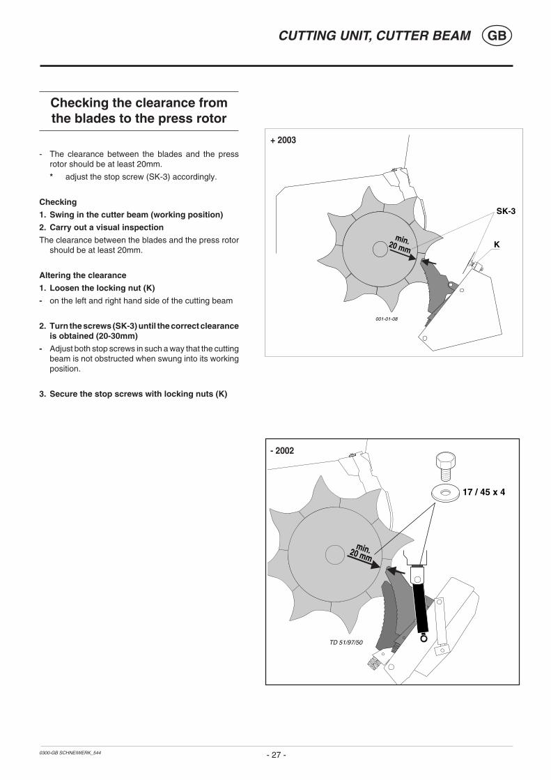
Checking the clearance fromthe blades to the press rotor
- The clearance between the blades and the pressrotor should be at least 20mm.
* adjust the stop screw (SK-3) accordingly.
Checking
1. Swing in the cutter beam (working position)
2. Carry out a visual inspection
The clearance between the blades and the press rotorshould be at least 20mm.
Altering the clearance
1. Loosen the locking nut (K)
- on the left and right hand side of the cutting beam
2. Turn the screws (SK-3) until the correct clearanceis obtained (20-30mm)
- Adjust both stop screws in such a way that the cuttingbeam is not obstructed when swung into its workingposition.
3. Secure the stop screws with locking nuts (K)
001-01-08
K
SK-3
min.20 mm
TD 51/97/50
17 / 45 x 4
min.20 mm
- 2002
+ 2003

9700-GB ALLG.WARTUNG (544)
MAINTENANCE GB
- 28 -
Advice for general maintenance
In order to keep the implement in good condition even after a longerservice life, please observe the following advice.
Safety points• Turn engine off when adjustment, service and repair work is to be
done.
• Do not work under the machine without safe support.
- Retighten all screws after the first hours of operation.
Spare partsa. The original components and accessories have been designed
especially for these machines and appliances.
b. We want to make it quite clear that components and accesoriesthat have not been supplied by us have not been tested by us.
c. The installation and/or use of such products can, therefore,negatively change or influence the construction characteristics ofthe appliance. We are not liablefor damages caused by theuse of components andaccessories that have not beensupplied by us.
d. Alterations and the use ofauxiliary parts that are notpermitted by the manufacturerrender all liability invalid.
AsbestosCertain sub-supplied components of thevehicle may contain asbestos due to technicalreasons. Observe the warning on spare parts.
Opening the side protectors
Open the locking bar „R“with a suitable aid (e.g.screw driver) andsimultaneously swingthe protector up.
Closing the sideprotectorsSwing the protector down, the locking bar engages automaticallyand locks the protector against unintentional opening.
Take care when entering the loadingarea
1. Secure the opened tailgate against unintentional closing (e.g. witha prop).
2. Use a suitable climbing aid (e.g. a stable ladder).
3. Do not enter the loading area when the p.t.o. is connected and thedrive motor is running.
4. Access door (only on trailers with metering rollers)
The access door in the left side wall must only be opened when thedrive motor is stopped.
Cleaning of machine parts
Attention!
Do not use high-pressure washers for the cleaning of
bearing- and hydraulic parts.- Danger of rust!
- After cleaning, grease the machine according to the lubricationchart and carry out a short test run.
- Cleaning with too high pressure may do damage to varnish.
Brake adjustment
See chapter "Brake unit"!
495.468
R
9700-GB ALLG.WARTUNG (544)
MAINTENANCE GB
- 29 -
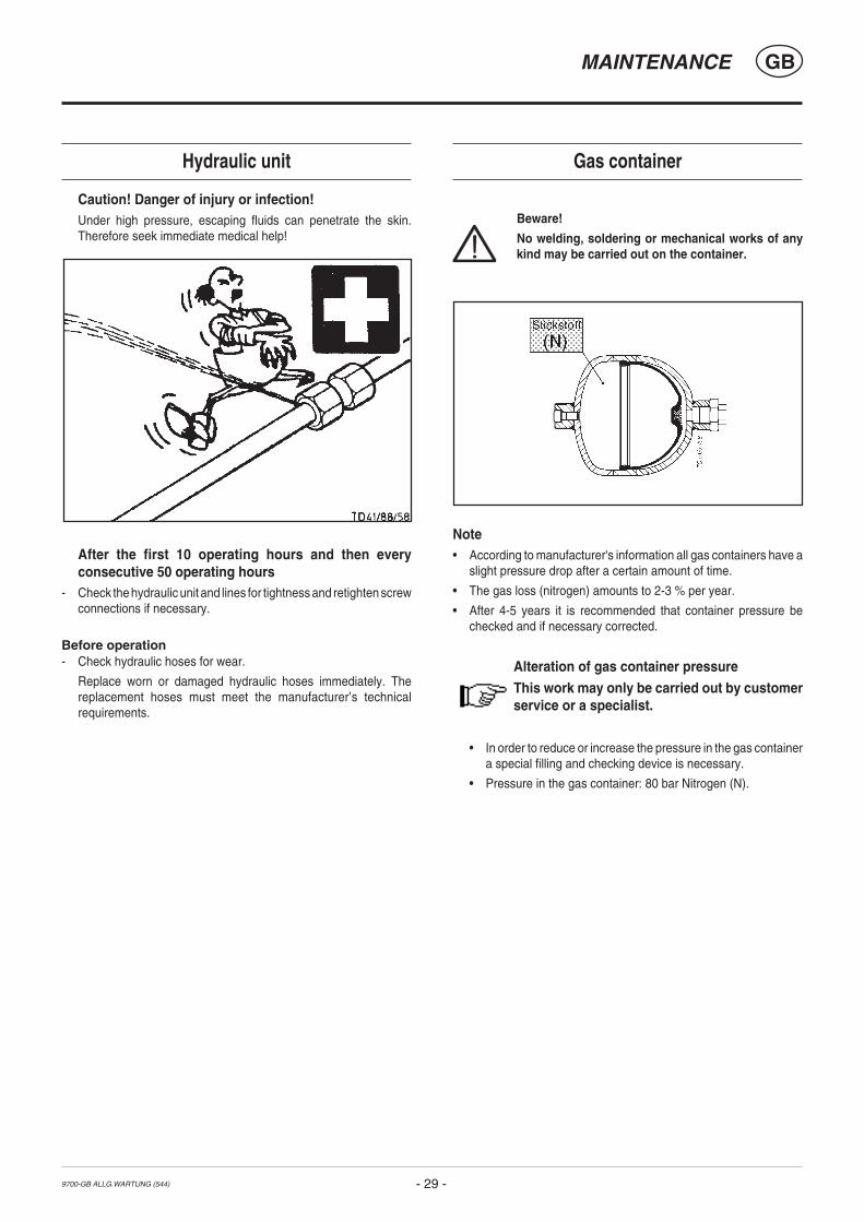
Hydraulic unit
Caution! Danger of injury or infection!Under high pressure, escaping fluids can penetrate the skin.Therefore seek immediate medical help!
After the first 10 operating hours and then everyconsecutive 50 operating hours
- Check the hydraulic unit and lines for tightness and retighten screwconnections if necessary.
Before operation- Check hydraulic hoses for wear.
Replace worn or damaged hydraulic hoses immediately. Thereplacement hoses must meet the manufacturer’s technicalrequirements.
Gas container
Beware!
No welding, soldering or mechanical works of anykind may be carried out on the container.
Note• According to manufacturer's information all gas containers have a
slight pressure drop after a certain amount of time.
• The gas loss (nitrogen) amounts to 2-3 % per year.
• After 4-5 years it is recommended that container pressure bechecked and if necessary corrected.
Alteration of gas container pressureThis work may only be carried out by customerservice or a specialist.
• In order to reduce or increase the pressure in the gas containera special filling and checking device is necessary.
• Pressure in the gas container: 80 bar Nitrogen (N).

9900-GB WARTUNG (544)
MAINTENANCE GB
- 30 -
TD 57/91/42
58
Cam wheel- For technical reasons the lubricating point (L) on the left front plate of the pick-
up drum must be greased when the pick-up is in operation.
In order to prevent possible accidents proceed with great care!
F=80
TD 57/91/51
(IV)F E T T
Press- Regulation of drive chain tension takes place through the tensioning screw
(58) after loosening lock nut.
- Tighten lock nut after tensioning chain.
Main bearing- Both main bearings should be greased every 80 runs.
Maintenance
Pick-up- Broken tines (53) can be replaced after removing
the corresponding stripper guard (54) withoutdisassembling the pick-up.
Luftdruck
Air pressure
Pick-up drive chain- Oil chain and check chain tension every 40 runs.
- Once a year remove chain guard, clean and oil chain as well as lubricating free-wheel.
- Regulation of the drive chain tension takes place through the tensioning screw (55) .
9900-GB WARTUNG (544)
MAINTENANCE GB
- 31 -
TD 57/91/46
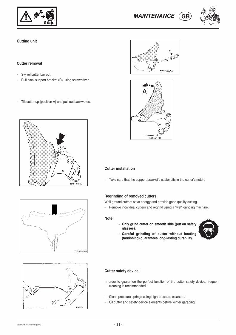
Cutter installation
- Take care that the support bracket's castor sits in the cutter's notch.
Regrinding of removed cuttersWell ground cutters save energy and provide good quality cutting.
- Remove individual cutters and regrind using a "wet" grinding machine.
Note!- Only grind cutter on smooth side (put on safety
glasses).
- Careful grinding of cutter without heating(tarnishing) guarantees long-lasting durability.
Cutter safety device:
In order to guarantee the perfect function of the cutter safety device, frequentcleaning is recommended.
- Clean pressure springs using high-pressure cleaners.
- Oil cutter and safety device elements before winter garaging.
Cutting unit
Cutter removal
- Swivel cutter bar out.
- Pull back support bracket (R) using screwdriver.
- Tilt cutter up (position A) and pull out backwards.

9900-GB WARTUNG (544)
MAINTENANCE GB
- 32 -
SSSS
TD 57/91/49
220 - 240 bar
Scraper floor chainsThe four scraper floor chains must be tensioned simultaneously but not strained. Theyshould sag slightly.
Retensioning of scraper floor chains- The tensioning screw (S) is located under the platform.
If length of tensioning screw is no longer adequate, then remove chain links.
- Always remove even numbered links (2, 4, 6, ...) from all four chains.
Adjusting measurement for endswitch
EUROPROFIThe adjustment is made with tailgate closed as well as with cutterbar swivelled in.
End switch for tailgate: X = 6 mm
End switch for automatic loader (up): X = 5 mm
End switch for cutting unit: X = 6 mm
Adjustment of oil pressure switch (3) 220 - 240 bar
EUROPROFI with regulating fittings
End switch for scraper floor: A = 6 mm
End switch (B) for tailgate: Loosen screws (SK).
Position the end switch in the elongatedholes so that the tailgate closing processfunctions as described in the chapter"ELECTRO HYDRAULICS".
Safeguarding the electrical unit
The electrical unit for the operation functions is protected with a 10A fuse.
The fuse (10A) is located front left on the distributor case.

9900-GB WARTUNG (544)
MAINTENANCE GB
- 33 -
- Remove screws (S) and metal sheet.
- From inside the load room pull stripper downward.
1) optional
Removing a stripper
A removed stripper.
Adjustment
min10 mm
TD 51/97/47
9900-GB WARTUNG (544)
MAINTENANCE GB
- 34 -
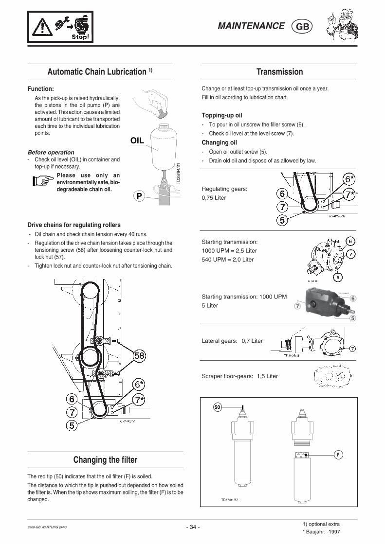
Transmission
Change or at least top-up transmission oil once a year.
Fill in oil acording to lubrication chart.
Topping-up oil- To pour in oil unscrew the filler screw (6).
- Check oil level at the level screw (7).
Changing oil- Open oil outlet screw (5).
- Drain old oil and dispose of as allowed by law.
Regulating gears:
0,75 Liter
Starting transmission:
1000 UPM = 2,5 Liter
540 UPM = 2,0 Liter
Starting transmission: 1000 UPM
5 Liter
Lateral gears: 0,7 Liter
Scraper floor-gears: 1,5 Liter
Automatic Chain Lubrication 1)
Function:As the pick-up is raised hydraulically,the pistons in the oil pump (P) areactivated. This action causes a limitedamount of lubricant to be transportedeach time to the individual lubricationpoints.
Before operation- Check oil level (OIL) in container and
top-up if necessary.
Please use only anenvironmentally safe, bio-degradeable chain oil.
Drive chains for regulating rollers - Oil chain and check chain tension every 40 runs.
- Regulation of the drive chain tension takes place through thetensioning screw (58) after loosening counter-lock nut andlock nut (57).
- Tighten lock nut and counter-lock nut after tensioning chain.
OIL
TD
29/9
4/21
P
Changing the filter
The red tip (50) indicates that the oil filter (F) is soiled.
The distance to which the tip is pushed out dependsd on how soiledthe filter is. When the tip shows maximum soiling, the filter (F) is to bechanged.
F
50
TD57/91/67
1) optional extra
* Baujahr: -1997
544 / RÄDER 9900-GB
WHEELS AND TYRES GB
- 35 -
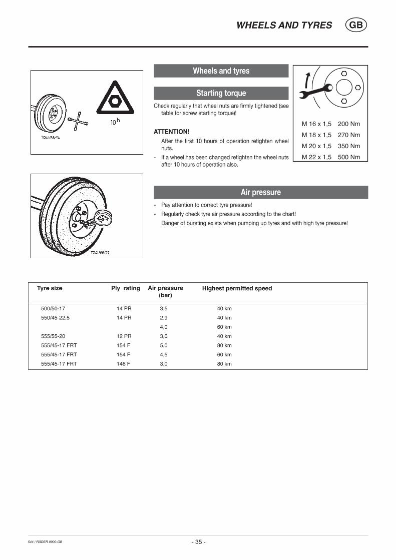
Wheels and tyres
Starting torqueCheck regularly that wheel nuts are firmly tightened (see
table for screw starting torque)!
ATTENTION! After the first 10 hours of operation retighten wheel
nuts.
- If a wheel has been changed retighten the wheel nuts after 10 hours of operation also.
Air pressure - Pay attention to correct tyre pressure!
- Regularly check tyre air pressure according to the chart!
Danger of bursting exists when pumping up tyres and with high tyre pressure!
Tyre size Ply rating Air pressure(bar)
Highest permitted speed
500/50-17 14 PR 3,5 40 km550/45-22,5 14 PR 2,9 40 km 4,0 60 km555/55-20 12 PR 3,0 40 km555/45-17 FRT 154 F 5,0 80 km555/45-17 FRT 154 F 4,5 60 km555/45-17 FRT 146 F 3,0 80 km

DRUCKLUFTBREMSE MIT ALB 9400 GB (540) - 36 -1) Wunschausrüstung
AIR BRAKE UNIT GB
Connecting the brake hoses- When connecting the brake hoses ensure: that the hose-
coupling sealing ring is clean, proper sealing, connection isaccording to markings"Compressed airstorage" (coloured red)to "Compressed airstorage" “Brakes"(coloured yellow) to"Brakes"
• Replace damagedsealing rings.
Stromversorgung des ABS(Antiblockiersystem) 1)
Das ABSfunktioniert ohnee l e k t r i s c h e rVersorgung nicht.
Vor Beginn derFahrt denStecker (1) beimS c h l e p p e rankuppeln.
• Zum Abstellen desWagens denStecker an dieSteckdose derKonsole kuppeln.Mit dem Schwenk-bügel (1a) wird der Stecker gegen Lösen gesichert.
- Vor der ersten täglichen Fahrt ist der Luftbehälter zuentwässern.
- Erst dann abfahren wenn der Luftdruck im Bremssystem 5,0
bar beträgt.Achtung!
Um ein ordnungsgemäßes Funktionieren der Bremsanlagezu gewährleisten, sind die Wartungsintervalle sowie dieBremseinstellung (Hub max. 30 mm) gewissenhafteinzuhalten.
Pflege und Wartung der Druckluftbremsanlage
LuftbehälterentwässerungDrain water from air reservoir daily.Using a piece of wire turn bolt on drain valve in a sidewaysdirection. Das Entwässerungsventil ist bei Verschmutzungaus dem Behälter zu schrauben und zu reinigen.
LeitungsfilterreinigungDie beiden Leitungsfilter sind je nach Betriebsbedingungen, imNormalfall etwa alle 3-4 Monate zu reinigen. Zur Reinigungsind die Sinterfilterpatronen herauszunehmen.
Arbeitsschritte:a) Verschlußstück (21) an den beiden Laschen hineindrücken
und Schieber (22) herausziehen.b)Verschlußstück mit O-Ring (23), Druckfeder und
Sinterfilterpatrone herausnehmen.c) Die Sinterfilterpatrone ist mit Nitro-Reinigungsmittel
auszuwaschen und mit Druckluft auszublasen. BeschädigteFilterpatronen sind zu erneuern.
d) Beim Zusammenbau in umgekehrter Reihenfolge ist daraufzu achten, daß der O-Ring (23) nicht in den Führungsschlitzfür den Schieber am Gehäuse verkantet!
BremseinstellungDer Kolbenhub an den Bremszylindern darf keinesfalls mehrals 30 mm aufweisen. Er ist daher von Zeit zu Zeit zuüberprüfen und ggf. nachzustellen.
Achtung!Lassen Sie allfällige Wartungs- und Reparaturarbeitenan der Bremsanlage von einer Fachwerkstätte odervon unserem Kundendienst durchführen.Für die Schnellläuferachse "300 x 200" gibt es einspezielles Wartungshandbuch welches beimKundendienst angefordert werden kann.
Einstellung- Die Einstellung erfolgt durch die Stellschraube (7).- Der Kolbenhub soll bei Neueinstellung 12 - 15 mm betragen.
TD70/91/4
max. 30 mm Hub
7
DRUCKLUFTBREMSE MIT ALB 9400 GB (540) - 37 -1) Wunschausrüstung
AIR BRAKE UNIT GB
TD13/92/12
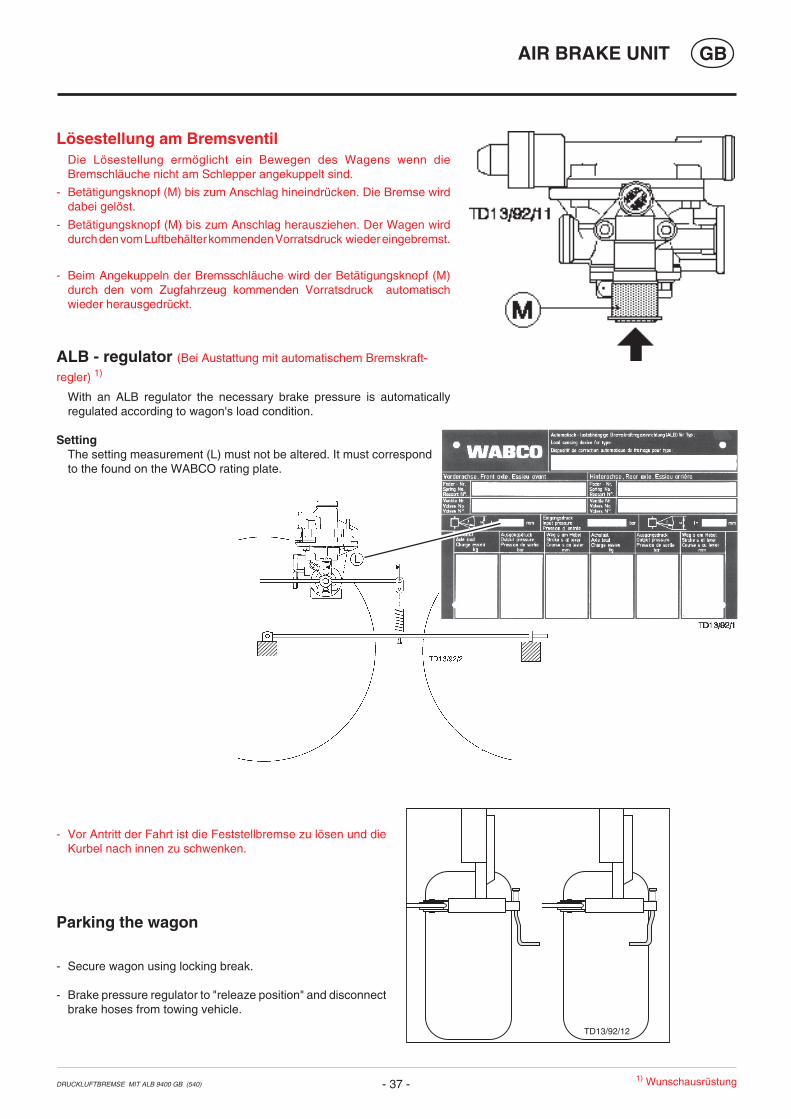
Lösestellung am BremsventilDie Lösestellung ermöglicht ein Bewegen des Wagens wenn dieBremschläuche nicht am Schlepper angekuppelt sind.
- Betätigungsknopf (M) bis zum Anschlag hineindrücken. Die Bremse wirddabei gelöst.
- Betätigungsknopf (M) bis zum Anschlag herausziehen. Der Wagen wirddurch den vom Luftbehälter kommenden Vorratsdruck wieder eingebremst.
- Beim Angekuppeln der Bremsschläuche wird der Betätigungsknopf (M)durch den vom Zugfahrzeug kommenden Vorratsdruck automatischwieder herausgedrückt.
ALB - regulator (Bei Austattung mit automatischem Bremskraft-
regler) 1)
With an ALB regulator the necessary brake pressure is automaticallyregulated according to wagon's load condition.
SettingThe setting measurement (L) must not be altered. It must correspondto the found on the WABCO rating plate.
- Vor Antritt der Fahrt ist die Feststellbremse zu lösen und dieKurbel nach innen zu schwenken.
Parking the wagon
- Secure wagon using locking break.
- Brake pressure regulator to "releaze position" and disconnectbrake hoses from towing vehicle.

Kenési terv40 F minden 40 menet után80 F minden 80 menet után
1 J 1-szer éventeFETT ZSÍR
= A zsírzógombok száma
II, III, IV Nézd a "Kenôanyagok" c. fejezetet* Variante
Nézd a gyártó utasításait!
H
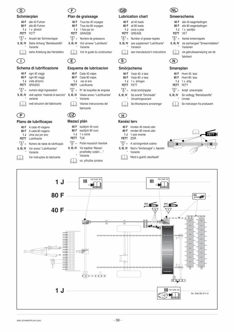
Schmierplan40 F alle 40 Fuhren80 F alle 80 Fuhren
1 J 1 x jährlichFETT FETT
= Anzahl der Schmiernippel
II, III, IV Siehe Anhang "Betriebsstoffe"* Variante
siehe Anleitung des Herstellers
Plan de graissage40 F Tous les 40 voyages80 F Tous les 80 voyages
1 J 1 fois par anFETT GRAISSE
= Nombre de graisseurs
II, III, IV Voir annexe "Lubrifiants"* Variante
Voir le guide du constructeur
Lubrication chart40 F all 40 loads80 F all 80 loads
1 J once a yearFETT GREASE
= Number of grease nipples
II, III, IV see supplement "Lubrificants"* Variation
see manufacturer’s instructions
Smeerschema40 F alle 40 wagenladingen80 F alle 80 wagenladingen
1 J 1 x jaarlijksFETT VET
= Aantal smeernippels
II, III, IV zie aanhangsel "Smeermiddelen"* Varianten
zie gebruiksaanwijzing van defabrikant
Mazací plán40 F kaûd˝ch 40 voz˘80 F kaûd˝ch 80 voz˘
1 J 1 x roËnÏFETT TUK
= PoËet mazacÌch hlaviËek
II, III, IV Viz kapitola "Mazacíprostfiedky vydání …"
* Varianta
viz. pfiíruËka v˝robce
D F GB NL
Esquema de lubricacion40 F Cada 40 viajes80 F Cada 80 viajes
1 J vez al anoFETT Lubrificante
= N° de boquillas de engrase
II, III, IV Véase anexo “Lubrificantes”* Variante
Véanse instrucciones delfabricante
Plano de lubrificaçao40 F A cada 40 viagens80 F A cada 80 viagens
1 J Uma vez por anoFETT Lubrificante
= Número de niples de lubrificação
II, III, IV Ver anexo ”Lubrificantes"* Variante
Ver instruções do fabricante
P
Schema di lubrificazione40 F ogni 40 viaggi80 F ogni 80 viaggi
1 J volta all'annoFETT GRASSO
= numero degli ingrassatori
II, III, IV vedi capitolo “materiali di esercizio”* variante
vedi istruzioni del fabbricante
CZ
9900 SCHMIERPLAN (544) - 38 -
FETT
Smörjschema40 F Varje 40: e lass80 F Varje 80: e lass
1 J 1 x årlingenFETT FETT
= Antal smörjnipplar
II, III, IV Se avsnitt ”Drivmedel”* Utrustningsvariant
Se tillverkarens anvisningar
Smøreplan40 F Hvert 40. lass80 F Hvert 80. lass
1 J 1 x årligFETT FETT
= Antall smørenipler
II, III, IV Se vedlegg "Betriebsstoffe"* Unntak
Se instruksjon fra produsent
I E S N
1(IV)
F E T T
Nr. 542.90.010.0
1 J
80 F
1 J
40 F
80 F
40 F
1 1 5(II)Ö L 41
(II)Ö L
1 (II)Ö L
(II)Ö L 5
51
6 2
1
6
HD SAE 90HD SAE 90
1 (3) 2
=
Kenési terv40 F minden 40 menet után80 F minden 80 menet után
1 J 1-szer éventeFETT ZSÍR
= A zsírzógombok száma
II, III, IV Nézd a "Kenôanyagok" c. fejezetet* Variante
Nézd a gyártó utasításait!
H
Schmierplan40 F alle 40 Fuhren80 F alle 80 Fuhren
1 J 1 x jährlichFETT FETT
= Anzahl der Schmiernippel
II, III, IV Siehe Anhang "Betriebsstoffe"* Variante
siehe Anleitung des Herstellers
Plan de graissage40 F Tous les 40 voyages80 F Tous les 80 voyages
1 J 1 fois par anFETT GRAISSE
= Nombre de graisseurs
II, III, IV Voir annexe "Lubrifiants"* Variante
Voir le guide du constructeur
Lubrication chart40 F all 40 loads80 F all 80 loads
1 J once a yearFETT GREASE
= Number of grease nipples
II, III, IV see supplement "Lubrificants"* Variation
see manufacturer’s instructions
Smeerschema40 F alle 40 wagenladingen80 F alle 80 wagenladingen
1 J 1 x jaarlijksFETT VET
= Aantal smeernippels
II, III, IV zie aanhangsel "Smeermiddelen"* Varianten
zie gebruiksaanwijzing van defabrikant
Mazací plán40 F kaûd˝ch 40 voz˘80 F kaûd˝ch 80 voz˘
1 J 1 x roËnÏFETT TUK
= PoËet mazacÌch hlaviËek
II, III, IV Viz kapitola "Mazacíprostfiedky vydání …"
* Varianta
viz. pfiíruËka v˝robce
D F GB NL
Esquema de lubricacion40 F Cada 40 viajes80 F Cada 80 viajes
1 J vez al anoFETT Lubrificante
= N° de boquillas de engrase
II, III, IV Véase anexo “Lubrificantes”* Variante
Véanse instrucciones delfabricante
Plano de lubrificaçao40 F A cada 40 viagens80 F A cada 80 viagens
1 J Uma vez por anoFETT Lubrificante
= Número de niples de lubrificação
II, III, IV Ver anexo ”Lubrificantes"* Variante
Ver instruções do fabricante
P
Schema di lubrificazione40 F ogni 40 viaggi80 F ogni 80 viaggi
1 J volta all'annoFETT GRASSO
= numero degli ingrassatori
II, III, IV vedi capitolo “materiali di esercizio”* variante
vedi istruzioni del fabbricante
CZ
9900 SCHMIERPLAN (544) - 39 -
FETT
Smörjschema40 F Varje 40: e lass80 F Varje 80: e lass
1 J 1 x årlingenFETT FETT
= Antal smörjnipplar
II, III, IV Se avsnitt ”Drivmedel”* Utrustningsvariant
Se tillverkarens anvisningar
Smøreplan40 F Hvert 40. lass80 F Hvert 80. lass
1 J 1 x årligFETT FETT
= Antall smørenipler
II, III, IV Se vedlegg "Betriebsstoffe"* Unntak
Se instruksjon fra produsent
I E S N
(II)Ö L
Nr. 546.90.011.0
14
HD SAE 90IIIHD SAE 90
III
(IV) (IV)
1 J
80 F
1 J
40 F
HD SAE 90III
F E T T F E T T
- 40 -9700-GB TECH.DAT (544)
GBTECHNICAL DATA
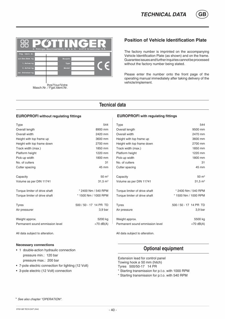
Position of Vehicle Identification Plate
The factory number is imprinted on the accompanyingVehicle Identification Plate (as shown) and on the frame.Guarantee issues and further inquiries cannot be processedwithout the factory number being stated.
Please enter the number onto the front page of theoperating manual immediately after taking delivery of thevehicle/implement.
* See also chapter "OPERATION".
Type
Overall length
Overall width
Height with top frame up
Height with top frame down
Track width (max.)
Platform height
Pick-up width
No. of cutters
Cutter spacing
Capacity
Volume as per DIN 11741
Torque limiter of drive shaft
Torque limiter of drive shaft
Tyres
Air pressurer
Weight approx.
Permanent sound emmission level
All data subject to alteration.
Type
Overall length
Overall width
Height with top frame up
Height with top frame down
Track width (max.)
Platform height
Pick-up width
No. of cutters
Cutter spacing
Capacity
Volume as per DIN 11741
Torque limiter of drive shaft
Torque limiter of drive shaft
Tyres
Air pressure
Weight approx.
Permanent sound emmission level
All data subject to alteration.
Tecnical data
Optional equipment
Extension lead for control panelTowing hook ø 50 mm (hitch)Tyres 500/50-17 14 PR* Starting transmission for p.t.o. with 1000 RPM* Starting transmission for p.t.o. with 540 RPM
Necessary connections
• 1 double-action hydraulic connection
pressure min.: 120 bar
pressure max.: 200 bar
• 7-pole electric connection for lighting (12 Volt)
• 3-pole electric (12 Volt) connection
EUROPROFI without regulating fittings EUROPROFI with regulating fittings
544
8900 mm
2420 mm
3600 mm
2700 mm
1850 mm
1220 mm
1800 mm
31
45 mm
50 m3
31,5 m3
* 2400 Nm / 540 RPM
* 1500 Nm / 1000 RPM
500 / 50 - 17 14 PR TD
3,9 bar
5200 kg
<70 dB(A)
544
9500 mm
2470 mm
3600 mm
2700 mm
1850 mm
1220 mm
1800 mm
31
45 mm
50 m3
31,5 m3
* 2400 Nm / 540 RPM
* 1500 Nm / 1000 RPM
500 / 50 - 17 14 PR TD
3,9 bar
5500 kg
<70 dB(A)
Ihre/Your/VotreMasch.Nr. / Fgst.Ident.Nr.
- 41 -9700-GB TECH.DAT (544)
GBTECHNICAL DATA
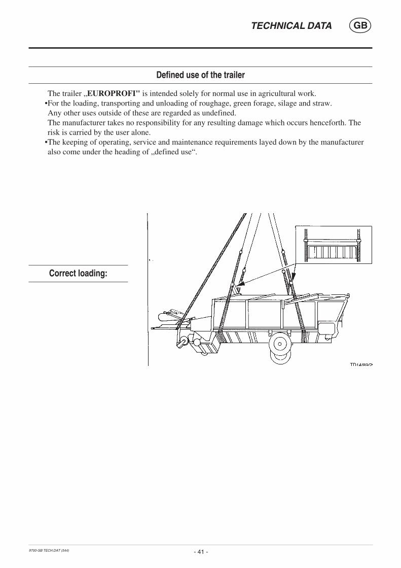
Defined use of the trailer
The trailer „EUROPROFI" is intended solely for normal use in agricultural work.•For the loading, transporting and unloading of roughage, green forage, silage and straw.Any other uses outside of these are regarded as undefined.The manufacturer takes no responsibility for any resulting damage which occurs henceforth. Therisk is carried by the user alone.
•The keeping of operating, service and maintenance requirements layed down by the manufactureralso come under the heading of „defined use“.
Correct loading:

Lu
bri
fica
nti
Ed
izio
ne
1997
DG
BI
Bet
rieb
ssto
ffe
Au
sgab
e 19
97
Lu
bri
can
ts
Ed
itio
n 1
997
Leis
tung
und
Leb
ensd
auer
der
Mas
chin
esi
nd v
on s
orgf
ältig
er W
artu
ng u
nd d
erV
erw
endu
ng g
uter
Bet
riebs
stof
fe a
bhän
gig.
Uns
ere
Bet
riebs
stof
fauf
listu
ng e
rleic
hter
td
ie
rich
tig
e
Au
swa
hl
ge
eig
ne
ter
Bet
riebs
stof
fe.
Im
Sch
mie
rpla
n
ist
de
r je
we
ils
ein
zuse
tze
nd
e
Be
trie
bss
toff
d
urc
h
die
Be
trie
bss
toff
ken
nza
hl
(z.B
. “I
II”)
sym
bo
lisi
ert
. A
nh
an
d
von
“Bet
riebs
stof
fken
nzah
l” ka
nn d
as g
efor
dert
eQ
ualit
ätsm
erkm
al u
nd d
as e
ntsp
rech
ende
Pro
dukt
der
Min
eral
ölfir
men
fes
tges
tellt
wer
den.
Die
Lis
te d
er M
iner
alöl
firm
en e
rheb
tke
inen
Ans
pruc
h au
f Vol
lstä
ndig
keit.
The
per
form
ance
and
the
lifet
ime
of th
efa
rm m
achi
nes
are
high
ly d
epen
ding
on
a ca
refu
l mai
nten
ance
and
app
licat
ion
of c
orre
ct l
ubri
cant
s. O
ur s
ched
ule
enab
les
an e
asy
sele
ctio
n of
sel
ecte
dpr
oduc
ts.
The
app
licab
le lu
bric
ants
are
sym
boliz
ed(e
g. “
III”)
. A
ccor
ding
to
this
lub
rican
tpr
oduc
t cod
e nu
mbe
r the
spe
cific
atio
n,qu
ality
and
bra
ndna
me
of o
il co
mpa
nies
may
eas
ily b
e de
term
ined
. The
list
ing
ofth
e oi
l co
mpa
nies
is
not
said
to
beco
mpl
ete.
Pre
stat
ies
en l
even
sduu
r va
n de
mac
hine
s zi
jn a
fhan
kelij
k va
n ee
nzo
rgvu
ldig
ond
erho
ud e
n he
t geb
ruik
van
goed
e sm
eerm
idde
len.
Dit
sch
em
a
verg
em
akk
elij
kt
de
go
ed
e
keu
ze
van
d
e
juis
tesm
eerm
idde
len.
III
IIIIV
VV
IV
II
HY
DR
AU
LIK
öL H
LPD
IN 5
1524
Tei
l 2
Sie
he A
nmer
kung
en* ** **
*
Mot
oren
öl S
AE
30
gem
äßA
PI C
D/S
F
mot
or o
il S
AE
30
acco
rdin
g to
AP
I CD
/SF
huile
mot
eur
SA
E 3
0 ni
veau
AP
I CD
/SF
oilo
mot
ore
SA
E 3
0 se
cond
osp
ecifi
che
AP
I CD
/SF
Get
riebe
öl S
AE
90
bzw
. 85
W-
140
gem
äß A
PI-
GL
5
gear
oil
SA
E 9
0 re
sp. S
AE
85
W-1
40 a
ccor
ding
to A
PI-
GL
5
huile
tran
smis
sion
SA
90
ouS
AE
85
W-1
40, n
ivea
u A
PI G
L5 oi
lio p
er c
ambi
e d
iffer
enzi
ali
SA
E 9
0 o
SA
E 8
5 W
-140
seco
ndo
spec
ifich
e A
PI-
GL
5
Kom
plex
fett
(DIN
51
502:
KP
1R
)
com
plex
gre
ase
grai
sse
com
plex
e
gras
so a
bas
e di
sap
oni
com
ples
si
Get
riebe
fließ
fett
(DIN
51
502:
GO
H
tran
smis
sion
gre
ase
grai
sse
tran
smis
sion
gras
so fl
uido
per
rid
utto
ri e
mot
orod
utto
ri
Li-F
ett (
DIN
51
502,
KP
2K
)
lithi
um g
reas
e
grai
sse
au li
thiu
m
gras
so a
l liti
o
Get
riebe
öl S
AE
90
bzw
. SA
E 8
5 W
-140
gem
äß A
PI-
GL
4 od
er A
PI-
GL
5
gear
oil,
SA
E 9
0 re
sp. S
AE
85
W-1
40ac
cord
ing
to A
PI-
GL
4 or
AP
I-G
L 5
huile
tran
smis
sion
SA
E 9
0 ou
SA
E 8
5 W
-140
, niv
eau
AP
I-G
L 4
ou A
PI-
GL
5
olio
per
cam
bi e
diff
eren
zial
i SA
E 9
0o
SA
E 8
5W-1
40 s
econ
do s
peci
fiche
AP
I-G
L 4
o A
PI-
GL
5
(II)
ÖL
gefo
rder
tes
Qua
lität
smer
kmal
requ
ired
qual
ity le
vel n
ivea
u
de p
erfo
rman
ce d
eman
dé
cara
tteris
tica
richi
esta
di
qual
ità
verla
ngte
kw
alite
itske
nmer
ken
Bet
rieb
ssto
ff-K
enn
zah
lL
ub
rica
nt
ind
icat
or
Co
de
du
lub
rifi
ant
Nu
mer
o c
arat
teri
stic
o d
ellu
bri
fica
nte
Olie
in
aand
rijv
inge
n vo
lgen
s de
gebr
uiks
aanw
ijzin
g ve
rwis
sele
n -
echt
er te
nmin
ste
1 x
jaar
lijks
.-
Öla
blaß
schr
aube
her
ausn
eh-
men
, das
Altö
l aus
lauf
en la
ssen
und
ordn
ungs
gem
äß e
ntso
rgen
.
Ge
trie
be
öl
ge
mä
ß
Be
trie
bsa
nle
itun
g
-je
doch
min
dest
ens
1 x
jähr
lich
wec
hsel
n.-
Öla
blaß
schr
aube
her
ausn
ehm
en, d
asA
ltöl a
usla
ufen
lass
en u
nd o
rdnu
ngs-
gem
äß e
ntso
rgen
.
Ge
ar
oils
a
cco
rdin
g
to
op
era
tin
gin
stru
ctio
ns -
how
ever
at
leas
t on
ce a
year
.-
Tak
e ou
t oil
drai
n pl
ug, l
et ru
n ou
t and
duly
dis
pose
was
te o
il.
Mot
ori
a qu
attr
o te
mpi
: bi
sogn
a ef
fettu
are
il ca
mbi
ode
ll'ol
io o
gni 1
00 o
re d
i fun
zion
amen
to e
que
llo d
ell'o
liope
r cam
bi c
ome
stab
ilito
nel
man
uale
del
le is
truz
ioni
per
l'uso
(tu
ttavi
a, a
lmen
o 1
volta
all'
anno
).-
Tog
liere
il t
appo
di s
caric
o a
vite
del
l’olio
; fa
r sc
olar
el’o
lio e
elim
inar
e l’o
lio c
ome
prev
isto
dal
la le
gge
anti-
inqu
inam
ento
am
bien
tale
.
Sm
eerm
idd
elen
co
de
Vo
or
he
t b
uite
n
ge
bru
ik
ste
llen
(win
terp
eri
od
e)
de
o
lie
-wis
el
uit
voe
ren
e
n
all
e
vetn
ipp
el
smee
rpun
ten
door
smer
en.
Bla
nke
met
aald
elen
(kop
pelin
gen
enz.
) met
een
prod
ukt
uit
groe
p "I
V"
van
dena
volg
ende
tab
el t
egen
cor
rosi
ebe
sche
rmen
.
Bef
ore
gara
ging
(w
inte
r se
ason
) an
oil
chan
ge a
nd g
reas
ing
of a
ll lu
bric
atin
gpo
ints
has
to
be d
one.
Unp
rote
cted
,bl
anc
met
al p
arts
out
side
(jo
ints
, et
c.)
have
to b
e pr
otec
ted
agai
nst c
orro
sion
with
a g
roup
"IV
" pr
oduc
t as
indi
cate
don
the
reve
rse
of th
is p
age.
Sm
eerm
idd
elen
Uit
gav
e 19
97
NL
Lu
bri
fian
ts
Éd
itio
n 1
997
F
Le b
on fo
nctio
nnem
ent e
t la
long
évité
des
mac
hine
s dé
pend
ent d
’un
entr
etie
nso
igne
ux e
t de
l’u
tilis
atio
n de
bon
slu
brifi
ants
. N
otre
lis
te f
acili
te l
e ch
oix
corr
ect d
es lu
brifi
ants
.
Sur
le ta
blea
u de
gra
issa
ge, o
n tr
ouve
un c
ode
(p.e
x."I
II")
se r
éfér
ant
à un
lubr
ifian
t don
né. E
n co
nsul
tant
ce
code
on
p
eu
t fa
cile
me
nt
dé
term
ine
r la
spéc
ifica
tion
dem
andé
e du
lub
rifia
nt.
La l
iste
des
soc
iété
s pé
trol
ière
s ne
prét
end
pas
d’êt
re c
ompl
ète.
Pou
r l’h
uile
tra
nsm
issi
on c
onsu
lter
leca
hier
d’e
ntre
tien
- au
moi
ns u
ne f
ois
par
an.
-R
etire
r le
bouc
hon
de v
idan
ge, l
aiss
erl'h
uil
e
s'é
cou
ler
et
l' éli
min
er
corr
ecte
men
t.
L'ef
ficie
nza
e la
dur
ata
della
mac
chin
a di
pend
ono
dall'
accu
rate
zza
della
sua
man
uten
zion
e e
dall'
impi
ego
dei
lubr
ifica
nti
adat
ti. I
l no
stro
ele
nco
dei
lubr
ifica
nti
Vi
agev
ola
nella
sce
lta d
el lu
brifi
cant
e gi
usto
.
Il lu
brifi
cant
e da
util
izza
rsi d
i vol
ta in
vol
ta è
sim
boliz
zato
nello
sch
ema
di lu
brifi
cazi
one
da u
n nu
mer
o ca
ratte
ristic
o(p
er e
s. "
III")
. In
bas
e al
"nu
mer
o ca
ratte
ristic
o de
llu
brifi
cant
e" s
i po
sson
o st
abili
re s
ia l
a ca
ratte
ristic
a di
qual
ità c
he i
l pr
oget
to c
orris
pond
ente
del
le c
ompa
gnie
petr
olife
re.
L'el
enco
del
le c
ompa
gnie
pet
rolif
ere
non
hapr
etes
e di
com
plet
ezza
.
Vor
Stil
legu
ng (
Win
terp
erio
de)
Ölw
echs
eldu
rchf
ühre
n un
d al
le F
etts
chm
iers
telle
nab
schm
iere
n. B
lank
e M
etal
lteile
auß
en(G
elen
ke, u
sw.)
mit
eine
m P
rodu
kt g
emäß
“IV
” in
der
um
seiti
gen
Tab
elle
vor
Ros
tsc
hütz
en.
Ava
nt
l’arr
êt
et
hiv
er:
vi
da
ng
er
et
grai
sser
. M
étau
x nu
s à
l' ex
téri
eur
prot
éger
ave
c un
pro
duit
type
“IV
” con
tre
la r
ouill
e (c
onsu
lter
tabl
eau
au v
erso
).
Effe
ttuar
e il
cam
bio
dell'
olio
ed
ingr
assa
re tu
tte le
par
ti ch
eric
hied
ono
una
lubr
ifica
zion
e a
gras
so p
rima
del
ferm
oin
vern
ale
della
mac
chin
a. P
rote
gger
e da
lla r
uggi
ne tu
ttele
par
ti m
etal
liche
est
erne
sco
pert
e co
n un
pro
dotto
ano
rma
di "I
V" d
ella
tabe
lla ri
port
ata
sul r
etro
del
la p
agin
a.
(IV)
FE
TT
- D
1 -

-O
SO 3
2/46
/68
ARN
ICA
22/4
6M
OTO
RO
IL H
D 3
0SI
GM
A M
ULT
I 15W
-40
SUPE
R T
RAC
TOR
OIL
UN
IVER
S.15
W-3
0
RO
TRA
HY
80W
-90/
85W
-140
RO
TRA
MP
80W
-90/
85W
-140
GR
MU
2G
R S
LLG
R L
FOR
OTR
A M
P 80
W-9
0R
OTR
A M
P 85
W-1
40
VITA
M G
F 32
/46/
68VI
TAM
HF
32/4
6SU
PER
KO
WAL
30
MU
LTI
TUR
BOR
AL S
UPE
R T
RAK
TOR
AL15
W-3
0
GET
RIE
BEÖ
L EP
90
GET
RIE
BEÖ
LH
YP 8
5W-9
0AR
ALU
B H
L 2
ARAL
UB
FDP
00AR
ALU
B FK
2G
ETR
IEBE
ÖL
HYP
90
AG
IP
AR
AL
*B
ei V
erbu
ndar
beit
mit
Naß
brem
sen-
schl
eppe
rn is
t die
inte
rnat
iona
leS
pezi
fikat
ion
J 20
Aer
ford
erlic
h
**H
ydra
ulik
öle
HLP
-(D
) + H
V
***
Hyd
raul
iköl
e au
fP
flanz
enöl
basi
s H
LP +
HV
Bio
logi
sch
abba
ubar
, des
halb
beso
nder
s um
wel
t-fre
undl
ich
IVA
NM
ER
KU
NG
EN
IIIV
IV
VII
III
Firm
a
Com
pany
Soc
iété
S
ocie
tá(I
V)
FE
TT
(II)
ÖL
*W
hen
wor
king
inco
njun
ctio
n w
ith w
et-
brak
e tra
ctor
s, th
ein
tern
atio
nal
spec
ifica
tion
J 20
A is
nece
ssar
y.
**H
ydra
ulic
oil
HLP
-(D
) + H
V.
***
Hyd
raul
ic o
il w
ithve
geta
ble
oil b
ase
HLP
+ H
V is
bio
-deg
rada
ble
and
is th
eref
ore
espe
cial
ly s
afe
for t
heen
viro
men
t.
HYD
RAU
LIKÖ
L H
LP 3
2/46
/68
SUPE
R 2
000
CD
-MC
*H
YDR
A H
YDR
. FLU
ID *
HYD
RAU
LIKÖ
L M
C 5
30 **
PLAN
TOH
YD 4
0N **
*
SUPE
R 2
000
CD
-MC
SUPE
R 2
000
CD
HD
SU
PER
IOR
20
W-3
0H
D S
UPE
RIO
R S
AE 3
0
SUPE
R 8
090
MC
HYP
OID
80W
-90
HYP
OID
85W
-140
MU
LTI F
ETT
2SP
EZIA
LFET
T FL
MPL
ANTO
GEL
2 N
GET
RIE
BEFL
IESS
FETT
NLG
I 0R
ENO
LIT
DU
RAP
LEX
EP 0
0PL
ANTO
GEL
00N
REN
OPL
EX E
P 1
HYP
OID
85W
-140
BA
YW
A
AVIL
UB
RL
32/4
6AV
ILU
B VG
32/
46M
OTO
RO
IL H
D 3
0M
ULT
IGR
ADE
HD
C 1
5W-4
0TR
ACTA
VIA
HF
SUPE
R 1
0 W
-30
GET
RIE
BEÖ
L M
Z 90
M M
ULT
IHYP
85W
-140
AVIA
MEH
RZW
ECKF
ETT
AVIA
ABS
CH
MIE
RFE
TTAV
IA G
ETR
IEBE
FLIE
SSFE
TTAV
IALU
B SP
EZIA
LFET
T LD
GET
RIE
BEÖ
L H
YP 9
0 EP
MU
LTIH
YP85
W-1
40 E
PA
VIA
ENER
GO
L SH
F 32
/46/
68VI
SCO
200
0EN
ERG
OL
HD
30
VAN
ELLU
S M
30
GEA
R O
IL 9
0 EP
HYP
OG
EAR
90
EPEN
ERG
REA
SE L
S-EP
2FL
IESS
FETT
NO
ENER
GR
EASE
HTO
OLE
X PR
914
2H
YPO
GEA
R 9
0 EP
HYP
OG
EAR
85W
-140
EP
BP
HYS
PIN
AW
S 32
/46/
68 H
YSPI
NAW
H 3
2/46
RX
SUPE
R D
IESE
L 15
W-4
0PO
WER
TRAN
SEP
X 80
W-9
0H
YPO
Y C
80W
-140
IMPE
RVI
A M
MO
CAS
TRO
LGR
EASE
LM
XEP
X 80
W-9
0H
YPO
Y C
80W
-140
CA
ST
RO
L
WIO
LAN
HS
(HG
) 32/
46/6
8W
IOLA
N H
VG 4
6 **
WIO
LAN
HR
32/
46 **
*H
YDR
OLF
LUID
*
MU
LTI-R
EKO
RD
15W
-40
PRIM
ANO
LR
EKO
RD
30
HYP
OID
-GET
RIE
BEÖ
L80
W-9
0, 8
5W-1
40M
EHR
ZWEC
KGET
RIE
BEÖ
L80
W-9
0
WIO
LUB
LFP
2W
IOLU
B G
FWW
IOLU
B AF
K 2
HYP
OID
-GET
RIE
BEÖ
L80
W-9
0, 8
5W-1
40
ENAK
HLP
32/
46/6
8EN
AK M
ULT
I 46/
68SU
PER
EVV
ARO
L H
D/B
SAE
30
UN
IVER
SAL
TRAC
TOR
OIL
SU
PER
HYP
OID
GA
90H
YPO
ID G
B 90
HO
CH
DR
UC
KFET
T LT
/SC
280
GET
RIE
BEFE
TT M
O 3
70EV
VA C
A 30
0H
YPO
ID G
B 90
HLP
32/
46/6
8H
LP-M
M32
/M46
MO
TOR
ÖL
100
MS
SAE
30M
OTO
RÖ
L 10
4 C
M 1
5W-4
0AU
STR
OTR
AC 1
5W-3
0
GET
RIE
BEÖ
L M
P 85
W-9
0G
ETR
IEBE
ÖL
B 85
W-9
0G
ETR
IEBE
ÖL
C 8
5W-9
0
LOR
ENA
46LI
TOR
A 27
RH
ENO
X 34
-G
ETR
IEBE
ÖL
B 85
W-9
0G
ETR
IEBE
ÖL
C 8
5W-1
40
OLN
A 32
/46/
68H
YDR
ELF
46/6
8PE
RFO
RM
ANC
E 2
B SA
E 30
800
0TO
UR
S 20
W-3
0 TR
ACTO
REL
F ST
15W
-30
TRAN
SELF
TYP
B 9
0 85
W-1
40TR
ANSE
LF E
P 90
85W
-140
EPEX
A 2
RO
LEXA
2M
ULT
I 2
GA
O E
PPO
LY G
OM
ULT
IMO
TIVE
1TR
ANSE
LF T
YP B
90
85W
-140
TRAN
SELF
TYP
BLS
80
W-9
0
NU
TO H
32/
46/6
8N
UTO
HP
32/4
6/68
PLU
S M
OTO
RÖ
L 20
W-3
0 U
NIF
ARM
15W
-30
GEA
RO
IL G
P 80
W-9
0 G
EAR
OIL
GP
85W
-140
MU
LTI P
UR
POSE
GR
EASE
HFI
BRAX
EP
370
NEB
ULA
EP
1G
P G
REA
SEG
EAR
OIL
GX
80W
-90
GEA
R O
IL G
X 85
W-1
40
ULT
RAM
AX H
LP 3
2/46
/68
SUPE
RTR
AC F
E 10
W-3
0* U
LTR
AMAX
HVL
P 32
**U
LTR
APLA
NT
40 **
*
SUPE
R H
PO 3
0ST
OU
15W
-30
SUPE
R T
RAC
FE
10W
-30
ALL
FLEE
T PL
US
15W
-40
HP
GEA
R O
IL 9
0od
er 8
5W-1
40TR
ANS
GEA
R O
IL 8
0W-9
0
MU
LTIL
UBE
EP
2VA
L-PL
EX E
P 2
PLAN
TOG
EL 2
N
REN
OLI
T LZ
R 0
00D
EGR
ALU
B ZS
A 00
0D
UR
APLE
X EP
1
TELL
US
S32/
S 46
/S68
TEL
LUS
T32
/T46
AGR
OM
A 15
W-3
0R
OTE
LLA
X 30
RIM
ULA
X 1
5W-4
0
SPIR
AX 9
0 EP
SPIR
AX H
D 9
0SP
IRAX
HD
85/
140
RET
INAX
AAL
VAN
IA E
P 2
SPEZ
. GET
RIE
BEFE
TT H
SIM
MN
IAG
REA
SE O
AER
OSH
ELL
GR
EASE
22
DO
LIU
MG
REA
SE R
SPIR
AX H
D 9
0SP
IRAX
HD
85W
-140
AZO
LLA
ZS 3
2, 4
6, 6
8 EQ
UIV
IS Z
S32
, 46,
68
RU
BIA
H 3
0M
ULT
AGR
I TM
15W
-20
TOTA
L EP
85W
-90
TOTA
L EP
B 8
5W-9
0M
ULT
IS E
P 2
MU
LTIS
EP
200
MU
LTIS
HT
1TO
TAL
EP B
85W
-90
DTE
22/
24/2
5D
TE 1
3/15
HD
20W
-20
DEL
VAC
123
0SU
PER
UN
IVER
SAL
15W
-30
MO
BILU
BE G
X 90
MO
BILU
BE H
D 9
0M
OBI
LUBE
HD
85W
-140
MO
BILG
REA
SE M
PM
OBI
LUX
EP 0
04M
OBI
LPLE
X 47
MO
BILU
BE H
D 9
0M
OBI
LUBE
HD
85W
-140
REN
OPL
EX E
P 1
HYP
OID
EW
90
HYP
OID
85W
-140
HYD
RAU
LIKÖ
L H
LP/3
2/46
/68
HYD
RAM
OT
1030
MC
*H
YDR
AULI
KÖL
520
**PL
ANTO
HYD
40N
***
MU
LTI 2
030
2000
TC
HYD
RAM
OT
15W
-30
HYD
RAM
OT
1030
MC
GET
RIE
BEÖ
L M
P 90
HYP
OID
EW
90
HYP
OID
85W
-140
MEH
RZW
ECKF
ETT
SPEZ
IALF
ETT
GLM
PLAN
TOG
EL 2
N
GET
RIE
BEFL
IESS
FETT
PLAN
TOG
EL 0
0N
HYD
RAN
32/
46/6
8D
ELTA
PLU
S SA
E 30
SUPE
R U
NIV
ERSA
L O
ILPO
NTO
NIC
N 8
5W-9
0 PO
NTO
NIC
MP
85W
-90
85W
-140
SUPE
R U
NIV
ERSA
L O
IL
MAR
SON
EP
L 2
NAT
RAN
00
MAR
SON
AX
2PO
NTO
NIC
MP
85W
-140
REN
OPL
EX E
P 1
REN
OG
EAR
SU
PER
809
0 M
CR
ENO
GEA
R H
YPO
ID 8
5W-1
40R
ENO
GEA
R H
YPO
ID 9
0
TITA
N H
YDR
AMO
T 1O
3O M
CTI
TAN
UN
IVER
SAL
HD
REN
OG
EAR
SU
PER
809
0 M
CR
ENO
GEA
R H
YPO
ID 8
5 W
-140
REN
OG
EAR
HYP
OID
90
REN
OSO
D G
FO 3
5D
UR
APLE
X EP
00
PLAN
TOG
EL 0
0N
ELA
N
FU
CH
S
GE
NO
L
MO
BIL
RH
G
SH
ELL
TO
TA
L
ELF
ES
SO
EV
VA
FIN
A
VA
LVO
LIN
E
VE
ED
OL
REN
OLI
N B
10/
15/2
0 R
ENO
LIN
B32
HVI
/46H
VIEX
TRA
HD
30
SUPE
R H
D 2
0 W
-30
MEH
RZW
EC
KGET
RIE
BEÖ
lSA
E90
HYP
OID
EW
90
MEH
RZW
ECKF
ETT
REN
OLI
T M
PD
UR
APLE
X EP
REN
OSO
D G
FO 3
5R
ENO
PLEX
EP
1H
YPO
ID E
W 9
0
--
AND
ARIN
32/
46/6
8H
D P
LUS
SAE
30M
ULT
IGR
ADE
SAE
80/9
0M
ULT
IGEA
R B
90
MU
LTIG
EAR
C S
AE 8
5W-1
40
MU
LTIP
UR
POSE
MU
LTIG
EAR
B 9
0M
ULT
I C S
AE 8
5W-1
40
WIN
TE
RS
HA
LL
HP
GEA
R O
IL 9
0od
er 8
5W-1
40
REN
OLI
N 1
025
MC
***
TITA
N H
YDR
AMO
T 10
30 M
C **
REN
OG
EAR
HYD
RA
*PL
ANTO
HYD
40N
***
REN
OLI
T M
PR
ENO
LIT
FLM
2R
ENO
LIT
ADH
ESIV
2PL
ANTO
GEL
2 N
CAS
TRO
LGR
EASE
LM
- D
2 -

GB-ANHANG TITELBLATT (341)
SUPPLEMENT
GB-ANHANG TITELBLATT (341)
The decision must be made, ”original” or ”imitation”? The decision is often governed byprice and a ”cheap buy” can sometimes be very expensive.
Be sure you purchase the ”Original” with the cloverleaf
symbol!
• Quality and precise fitting
- Operating safety.
• Reliable operation
• Longer lasting
- Economy
• Guaranteed availability through your
Pöttinger Sales Service.
Things will run better with
genuine Pöttinger parts
The original cannot be copied
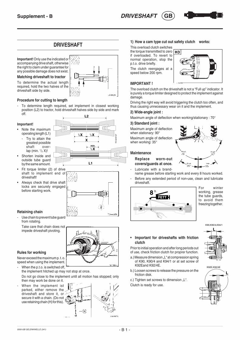
0000-GB GELENKWELLE (341)
DRIVESHAFT GBSupplement - B
1) How a cam type cut out safety clutch works:This overload clutch switchesthe torque transmitted to zeroif overloaded. To revert tonormal operation, stop thep.t.o. drive briefly.The clutch reengages at aspeed below 200 rpm.
IMPORTANT !The overload clutch on the driveshaft is not a “Full up” indicator. Itis purely a torque limiter designed to protect the implement againstdamage.Driving the right way will avoid triggering the clutch too often, andthus causing unnecessary wear on it and the implement.
2) Wide-angle joint :Maximum angle of deflection when working/stationary : 70°
3) Standard joint :Maximum angle of deflectionwhen stationary: 90°Maximum angle of deflectionwhen working: 35°
MaintenanceReplace worn-outcovers/guards at once.
- Lubricate with a brand-name grease before starting work and every 8 hours worked.
- Before any extended period of non-use, clean and lubricatedriveshaft.
For winterworking, greasethe tube guards,to avoid themfreezing together.
• Important for driveshafts with frictionclutch
Prior to initial operation and after long periods outof use, check friction clutch for proprer function.a.) Measure dimension „L“ at compression spring
of K90, K90/4 and K94/1 or at set screw ofK92Eand K92/4E.
b.) Loosen screws to release the pressure on thefriction disk.
c.) Tighten set screws to dimension „L“.Clutch is ready for use.
DRIVESHAFT
Important! Only use the indicated oraccompanying drive shaft, otherwisethe right to claim under guarantee forany possible damage does not exist.
Matching driveshaft to tractorTo determine the actual lengthrequired, hold the two halves of thedriveshaft side by side.
Procedure for cutting to length- To determine length required, set implement in closest working
position (L2) to tractor, hold driveshaft halves side by side and markoff.
Important!• Note the maximum
operating length (L1)- Try to attain the
greatest possibleshaft over-lap (min. 1/2 X)!
• Shorten inside andoutside tube guardby the same amount.
• Fit torque limiter (2) of driveshaft to implement end ofdriveshaft!
• Always check that drive shaftlocks are securely engagedbefore starting work.
Retaining chain- Use chain to prevent tube guard
from rotating.Take care that chain does notimpede driveshaft pivoting.
Rules for workingNever exceed the maximum p. t. o.speed when using the implement.- When the p.t.o. is switched off,
the implement hitched up may not stop at once.Do not go close to the implement until all motion has stopped; onlythen may work be done on it.
- When the implement istparked, either remove thedriveshaft and store it, orsecure it with a chain. (Do notuse retaining chain (H) for this).
XX
L1
L2
X
Xmin.
TD
52/
97/3
7
- B 1 -
8 h
FETT
L
L
K92E,K92/4E
K90,K90/4,K94/1

ALOIS PÖTTINGER Maschinenfabrik Gesellschaft m.b.H.
A-4710 Grieskirchen; Industriegelände 1
9800
D/F
/GB
/NL/
I/E/P
/S/S
F E
G K
onfo
rmitä
tser
kl.
Grieskirchen, 02.12.2002
pa. Ing. H. MenzlEntwicklungsleitung
Silierwagen EUROPROFI 3, Type 544
EN 292-1 : 1991 EN 292-2 : 1991
Appendix 1
GB
________________________ ________________________________(Place and date of issue) (Name and job function of authorized person)
EC Certificate of Conformityconforming to EEC Directions 98/37
We _______________________________________________________________________(name of supplier)
_________________________________________________________________________(full address of company - where this concerns authorized agents within the Common Market, also state the companyname and manufacturer)
declare in sole responsibility, that the product
_________________________________________________________________________(make, model)
to which this certificate applies, conforms to the basic safety and health requirements ofEEC Directions 98/37,(if applicable)and to the other relevant EEC Directions.
_________________________________________________________________________(title and/or number and date of issue of the other EEC Directions)
(if applicable)To effect correct application of the safety and health requirements stated in the EEC Directions,the following standards and/or technical specifications were consulted:
_________________________________________________________________________(title and/or number and date of issue of standards and/or specifications)

Following the policy of the PÖTTINGERGes.m.b.H to improve their products as
technical developments continue, PÖTTINGER reservethe right to make alterations which must not necessarilycorrespond to text and illustrations contained in thispublication, and without incurring obligation to alterany machines previously delivered.
Technical data, dimensions and weights are given asan indication only. Responsibility for errors or omissionsnot accepted.
Reproduction or translation of this publication, in wholeor part, is not permitted without the written consent ofthe ALOIS PÖTTINGER
Maschinenfabrik Gesellschaft m.b.H.
A-4710 Grieskirchen.
All rights under the provision of the Copyright Act arereserved.
La société PÖTTINGER Ges.m.b.H amélioreconstamment ses produits grâce au progrès
technique. C'est pourquoi nous nous réservons le droitde modifier descriptions et illustrations de cette noticed'utilisation, sans qu'on en puisse faire découler undroit à modifications sur des machines déjà livrées.
Caractéristiques techniques, dimensions et poids sontsans engagement. Des erreurs sont possibles.
Copie ou traduction, même d'extraits, seulement avecla permission écrite de
ALOIS PÖTTINGER
Maschinenfabrik Gesellschaft m.b.H.
A-4710 Grieskirchen.
Tous droits réservés selon la réglementation des droitsd'auteurs.
De PÖTTINGER Ges.m.b.H werkt perma-nent aan de verbetering van hun produkten in
het kader van hun technische ontwikkelingen. Daarommoeten wij ons veranderingen van de afbeeldingen enbeschrijvingen van deze gebruiksaanwijzingvoorbehouden, zonder dat daaruit een aanspraak opveranderingen van reeds geieverde machines kanworden afgeleid.
Technische gegevens, maten en gewichten zijn nietbindend. Vergissingen voorbehouden.
Nadruk of vertailing ook gedeeltelijk, slechts metschiftelijke toestemming van de
ALOIS PÖTTINGER
Maschinenfabrik Gesellschaft m.b.H.
A-4710 Grieskirchen.
Alle rechten naar de wet over het auteursrechtvoorbehouden.
La empresa PÖTTINGER Ges.m.b.H seesfuerza contínuamente en la mejora
constante de sus productos, adaptándolos a laevolución técnica. Por ello nos vamos obligados areservarnos todos los derechos de cualquiermodificación de los productos con relación a lasilustraciones y a los textos del presente manual, sinque por ello pueda ser deducido derecho alguno a lamodificación de máquinas ya suministradas.
Los datos técnicos, las medidas y los pesos seentienden sin compromiso alguno.
La reproducción o la traducción del presente manualde instrucciones, aunque sea tan solo parcial, requierede la autorización por escrito de
ALOIS PÖTTINGER
Maschinenfabrik Gesellschaft m.b.H.
A-4710 Grieskirchen.
Todos los derechos están protegidos por la ley de lapropiedad industrial.
D
NL
GBF
E
Im Zuge der technischen Weiterentwicklungarbeitet die PÖTTINGER Ges.m.b.H ständig
an der Verbesserung ihrer Produkte.
Änderungen gegenüber den Abbildungen und Be-schreibungen dieser Betriebsanleitung müssen wiruns darum vorbehalten, ein Anspruch auf Änderungenan bereits ausgelieferten Maschinen kann daraus nichtabgeleitet werden.
Technische Angaben, Maße und Gewichte sind unver-bindlich. Irrtümer vorbehalten.
Nachdruck oder Übersetzung, auch auszugsweise,nur mit schriftlicher Genehmigung der
ALOIS PÖTTINGER
Maschinenfabrik Gesellschaft m.b.H.
A-4710 Grieskirchen.
Alle Rechte nach dem Gesetz des Urheberrecht vorbe-halten.
La PÖTTINGER Ges.m.b.H è costantementeal lavoro per migliorare i suoi prodotti
mantenendoli aggiornati rispetto allo sviluppo dellatecnica.
Per questo motivo siamo costretti a riservarci la facoltàdi apportare eventuali modifiche alle illustrazioni e alledescrizioni di queste istruzioni per l’uso. Allo stessotempo ciò non comporta il diritto di fare apportaremodifiche a macchine già fornite.
I dati tecnici, le misure e i pesi non sono impegnativi.Non rispondiamo di eventuali errori. Ristampa otraduzione, anche solo parziale, solo dietro consensoscritto della
ALOIS PÖTTINGER
Maschinenfabrik Gesellschaft m.b.H.
A-4710 Grieskirchen.
Ci riserviamo tutti i diritti previsti dalla legge sul dirittod’autore.
I
V d˘sledku technickÈho v˝voje pracujefirma PÖTTINGER Ges.m.b.H neust·le
na zlepöenÌ sv˝ch v˝robk˘.
ZmÏny v n·vodu k pouûÌv·nÌ si v˝robce vyhrazuje.Poûadavky na zmÏnu n·vodu k pouûÌv·nÌ napr·vÏ dodanÈ stroje nemohou b˝t vyvozov·ny.
TechnickÈ ˙daje, rozmÏry a hmotnosti jsounez·vaznÈ.
Dotisk nebo nov˝ p¯eklad je moûn˝ pouze zapÌsemnÈho souhlasu firmy
ALOIS PÖTTINGER
Maschinenfabrik Gesellschaft m.b.H.
A-4710 Grieskirchen
Vöechna pr·va podlÈhajÌ autorskÈmu pr·vu.
CZ В ходе технического развития фирма«ПЁТТИНГЕР Гез.м.б.Х.» постояннозанимается усовершенствованием своей
продукции.
В связи с этим мы сохраняем за собой право вноситьизменения в рисунки и описания этой инструкции поэксплуатации, однако,требование вносить такиеизменения в уже поставленные машины предъявлениюне подлежит.
Технические данные, указание размеров и массы даютсябез обязательств. Ошибки не исключены.
Перепечатка или перевод, в том числе отрывками,разрешается только с письменного согласия фирмы
«АЛОЙС ПЁТТИНГЕР
Машиненфабрик Гезельшафт м.б.Х.»
А-4710 Грискирхен.
С сохранением всех прав в соответствии с авторскимправом.
RUS
S Beroende på den tekniska utvecklingenarbetar PÖTTINGER Ges.m.b.H. på att
förbättra sina produkter.
Vi måste därför förbehålla oss förändringar gentemotavbildningarna och beskrivningarna i dennabruksanvisning. Däremot består det inget anspråk påförändringar av produkter beroende av dennabruksanvisning.
Tekniska uppgifter, mått och vikter är oförbindliga. Felförbehållna.
Ett eftertryck och översättningar, även utdrag, får endastgenomföras med skriftlig tillåtelse av
ALOIS PÖTTINGER
Maschinenfabrik Gesellschaft m.b.H.
A – 4710 Grieskirchen
Alla rättigheter enligt lagen om upphovsmannarättenförbehålls.
A mûszaki termékfejlesztés folyamatában aPöttinger Ges.m.b.H. folyamatosan dolgozik
termékei minôségének javításán.Ezen kezelési utasítás ábráinak és leírásainakváltoztatási jogát fenntartjuk, emiatt nem lehetköveteléssel fellépni egy már kiszállított gépmegváltoztatásával kapcsolatban.A mûszaki adatok, méretek, tömegek, kötelezettségnélküliek. A tévedések joga fenntartva.Utánnyomás vagy fordítás, akárcsak kivonatosan is,csak azALOIS PÖTTINGERMaschinenfabrik Gesellschaft m.b.H.A-4710 Grieskirchen írásos engedélyével történhet.A szerzôi jogi törvény értelmében minden jog fenntartva.
HU
PLW sensie dalszego rozwoju technicznegoPoettinger nieustannie pracuje nadulepszaniem swoich produktÛw. W zwiπzku z
powyøszym zastrzegamy sobie prawo do zmian wschematach i opisach znajdujπcych siÍ w niniejszejinstrukcji obs≥ugi.Nie wyklucza siÍ prawa do zmian rÛwnieø w przypadkujuø dostarczonych maszyn.Dane techniczne, wymiary i ciÍøary nie sπ wielkoúciamiostatecznymi. Dopuszcza siÍ moøliwoúÊ pojawieniasiÍ b≥edÛw.Powielanie bπdü t≥umaczenia, rÛwnieø wyrywkowe,wy≥πcznie za pisemnπ zgodπALOIS POTTINGERMaschinenfabrik Gesellschaft m.b.H.A-4710 GrieskirchenWszelkie prawa w≥πcznie z prawami autorskimizastrzeøone.

GEBR. PÖTTINGER GMBHServicezentrumSpöttinger-Straße 24Postfach 1561D-86 899 LANDSBERG / LECHTelefon:
Ersatzteildienst: 0 81 91 / 92 99 - 166 od. 169Kundendienst: 0 81 91 / 92 99 - 130 od. 231
Telefax: 0 81 91 / 59 656
ALOIS PÖTTINGERMaschinenfabrik Gesellschaft m.b.HA-4710 Grieskirchen
Telefon: 0043 (0) 72 48 600-0Telefax: 0043 (0) 72 48 600-511
e-Mail: [email protected]: http://www.poettinger.co.at
GEBR. PÖTTINGER GMBHStützpunkt NordWentruper Mark 10D-48 268 GrevenTelefon: (0 25 71) 93 45 - 0
Ersatzteildienst: (0 25 71) 93 45 - 11Kundendienst: (0 25 71) 93 45 - 12
Telefax: (0 25 71) 93 45 - 14
PÖTTINGER France129 b, la ChapelleF-68650 Le Bonhomme
Tél.: 03.89.47.28.30Fax: 03.89.47.28.39