the engineering method of calculation of the remaining ... · the engineering method of calculation...
TRANSCRIPT

VOL. 10, NO 22, DECEMBER, 2015 ISSN 1819-6608
ARPN Journal of Engineering and Applied Sciences ©2006-2015 Asian Research Publishing Network (ARPN). All rights reserved.
www.arpnjournals.com
10511
THE ENGINEERING METHOD OF CALCULATION OF THE REMAINING LIFE OF THE BUS BODY SAFE OPERATION ON THE BASIS OF
ESTIMATION OF ITS CORROSION DETERIORATION
Ovchinnikov N. A., Kalmikov B. Y., Stradanchenko S. G., Kozyreva E. A. and Chefranova O. V. Don State Technical University, Shakhty, Russia
E-Mail: [email protected]
ABSTRACT
The article is devoted to the solution of practical problems in the field of buses passive safety and particularly to the determination of passenger vehicles service limits according to the safety conditions and the body structural strength. The authors have developed a step-by-step strategy of distribution of a blow general energy on the bus pillars taking into account irregularity of loading on axes. The authors have calculated the breaking load for the body material possessing ideal elastoplastic properties. The authors have calculated the predictable moment of section resistance for the body material taking into account the corrosive deterioration of its elements during operating time Т, years. The remaining life of the bus body safe operation on the basis of the estimation of its corrosive deterioration is proved. Keywords: bus, body, passive safety, strength, engineering estimation, corrosive deterioration, body deformation, breaking load, safe operation period, remaining life.
INTRODUCTION
According to the statistical data from the State Road Traffic Safety Inspection, in the Russian Federation the share of buses in the total number of the motor car park of the country is about 2 %, while the number of road accidents involving buses is about 5,5-6 % of the total number of traffic accidents. It is necessary to underline that statistically road accidents with participation of buses have the heaviest consequences either for the driver and passengers of the bus or for the other participants of movement (pedestrians, drivers and passengers of other vehicles), due to large quantities of people and the bus weight. Buses can be defined as the most dangerous kind of transport according to the risk level taken by passengers and drivers which is estimated by the relation of number of victims to 10 000 vehicles [1].
The Russian Federation and a number of European countries apply The Rules of the United Nations Economic Commission for Europe (UNECE) for certification of vehicles. The Rules estimate the bus body structural strength and rationality of the passenger salon design. The maintenance of the set level of the bus body strength (assemblies and elements as well as welded connections) directly depends on the complex analysis of the factors which determine the operating reliability of the vehicle tested. However, the existing methods of analysis of the body safety and reliability can be applied only for the buses that have been recently produced with the purpose to obtain the certificate of “Approval of a vehicle type”. They do not consider the conformity to these requirements in the course of all life cycle of a product as well as specificity of buses operation and their interaction with the environment.
In general the Rules of UNECE (except for a few rules) do not consider changes of the requirements specified in them in the course of all life cycle of a product [3], and they do not consider specificity of buses operation and their interaction with the environment. While operating buses in different climatic areas of Russia and on various categories of roads, corrosion-fatigue centers appear on the bearing elements of the body in 3-4 years. In 5-6 years the corrosion damage of the elements leads to the accelerated loss of strength of the whole body [4].
In the international practice experts test vehicles at various stages of operation. As a result the data on the safety level during the total life cycle is obtained. So if domestic manufacturers of buses do not have information on a vehicle technical state being in operation, they do not follow the general tendency and moreover do not observe those Rules of UNECE ordering the performance of certain requirements during operation of a body bearing elements.
In technical maintenance of a car there is a concept of “a mileage until a vehicle major overhaul”. Upon the achievement of the value of this mileage a vehicle shall be subjected to major overhaul. To calculate the value of the mileage it is necessary to correct the value of the mileage until the vehicle major overhaul specified by manufacturer from the point of view of non-failure operation of its units and assemblies. It can be done by means of a number of correcting coefficients [5].
In Technical Regulations [6] it is specified, that the design of a vehicle of a certain category and purpose shall minimize injuring influences on people being in a vehicle and provide possibility of their evacuation in case of a road accident. Besides, the design of vehicles of М2 and М3 categories provides the compliance with the

VOL. 10, NO 22, DECEMBER, 2015 ISSN 1819-6608
ARPN Journal of Engineering and Applied Sciences ©2006-2015 Asian Research Publishing Network (ARPN). All rights reserved.
www.arpnjournals.com
10512
special safety requirements to big capacity passenger vehicles.
However, the existing methods of determination of the mileage until a vehicle major overhaul solve the problem of calculation of the vehicle service limit in order to minimize the failure of its units. Hence, for the maintenance of Technical Regulations requirements [6], it is necessary to develop the methods which can determine the limiting value of a vehicle mileage upon achievement of which its assemblies, units and systems will not be considered as complying with the safety conditions for its design.
To maintain the purposes specified in Technical Regulations [6], it is necessary to review the methods of determination of the mileage until a vehicle major overhaul. Thus, the subject of the given research can be defined as urgent due to the following reasons: it solves the problem of determination of the bus
bodies safe service life; determines the limiting mileage at which the bus body does not comply with the strength requirements;
it determines the corrected terms of the bus body major overhaul, considering safety issues of its design.
Foundation of the scientific approach to solution of the problem
The vehicle body is the major element of its passive safety system. Its level can be estimated by the instruments measuring its crash-strength properties [7]. They include deformation by the size of which it is possible to determine the expenditure of energy required to overturn the car and the resistance forces when being moved in the overturned state. Besides, it is possible to determine yield points σT, breaking points σB, intensity of deformations εiT and εiB corresponding to yield points σT
and breaking points σB, the hardening exponents of the materials of which the damaged details of vehicles are made. It is also possible to estimate the vehicle traverse speed at the moment of collision or overturning.
Nowadays there are various approaches and methods used for determination of values of breaking loads of a body bearing elements [8]. There are methods allowing toestimate the breaking loads for each power section of a bus body by means of special software.
The optimum term of the bus safety operation will be determined on the basis of conformity condition of the bus body strength characteristics to technical requirements [2, 6]. The estimation of the body frame strength begins with the analysis of values of the maximum pressures received by the interwindow side-frame pillars (Figure 1), which are the most responsible elements when testing safety level.
1-9 - numbers of bus body pillars
Figure-1. Designation of interwindow side pillars of bus body frame.
Taking into account the body frames structural
features of the buses of average and big classes, it is possible to determine their safety in the conditions of overturning (according to Rules of UNECE #66) by means of the total breaking strength of their separate constituent parts: a front, a back, intermediate parts. In case of bus overturning according to the procedure stated in the Rules, all energy of the blow at symmetric breaking is mostly absorbed at the expense of deformability of cross power sections of the body and its parts. Each section represents a closed rectangular frame which contains a roof bow, two interwindow side-frame pillars with adjoining braces (stiffeners), a bottom cross-beam. Forward and back sections have a more complex scheme of power section.
In case of lateral overturning the longitudinal elements of the roof (stringers), overwindow and underwindow side-frame belts as well as side-frame panels provide interconnection of cross power sections only and in general do not accept considerable lateral loadings. Therefore when estimating the body structural safety the strength of its cross power sections and particularly of interwindow side pillars of the bus body are of primary importance.
On the basis of the earlier researches results [9, 10, 11, 19], dealing with computer modelling of buses overturning with the conformity to the Rules of UNECE #66 requirements (Figure 2), the tests results (Figure 3) and the analysis of consequences of the real road accidents connected with buses overturning (Figure-4), the following facts can be established: The behaviour of cross power section at a bus body
overturning can be characterized by occurrence of 6 “plastic hinges” (Figures 2 - 4);
The maximum turns are given by subwindow plastic hinges (2 and 5 in Figures 2 - 4), causing the maximum penetration of cross power section elements of a bus body into the “remaining space”.

VOL. 10, NO 22, DECEMBER, 2015 ISSN 1819-6608
ARPN Journal of Engineering and Applied Sciences ©2006-2015 Asian Research Publishing Network (ARPN). All rights reserved.
www.arpnjournals.com
10513
Figure-2. Places of “plastic hinges” occurrence at cross power section at a bus body overturning (modeling
results).
Figure-3. Places of “plastic hinges” occurrence at cross power section at a bus body overturning (real tests results).
Figure-4. Places of “plastic hinges” occurrence at cross power section at a bus body overturning (results of the
analysis of real road accidents involving buses overturning).
The article suggests the method which gives a possibility to distribute the blow total energy at bus overturning among the main bearing elements of its body depending on distribution of loads on axes. The method determines the values of breaking loads by deformation degree of the members and forecasts the body structural deformation using the known corrosion rate of the body elements [12, 13]. Comparing the experimental data of several body frame rings deformation at level of 1250 and 500 mm from the floor with the deformation permissible values, the method can estimate the remaining space integrity and the safe operation term. The method includes five stages.
Stage I: Preparation. It determines the coefficients of the bus axes loading distribution;
the bus center of gravity coordinates;
the blow total energy.
Stage II: The distribution of the blow total energy on the bus body pillars taking into account the irregularity of axes loading distribution.
Stage III: The calculation of breaking load of the body that is made of the material possessing: rigid-plastic properties;
ideal elastoplastic properties.
Stage IV: The calculation of the predictable moment of section resistance for the body material taking into account corrosion deterioration of its elements during operation Т, years.
Stage V: Foundation of the remaining life of the bus body safe operation on the basis of estimation of its corrosion deterioration.
Stage I requires gathering and determination of initial data for carrying out the calculations. The data is obtained in the following consequence:
a) distance from the wheels plane of support to the plane of the body contact, h, mm (overturning height).
b) the bus orientation with regard to axes of co-ordinates: plane (x;y) coincides with the wheels plane of
support;
plane (y; z) is parallel to the plane of the body front panel and goes through the central part of the first body pillar;

VOL. 10, NO 22, DECEMBER, 2015 ISSN 1819-6608
ARPN Journal of Engineering and Applied Sciences ©2006-2015 Asian Research Publishing Network (ARPN). All rights reserved.
www.arpnjournals.com
10514
plane (x; z) is perpendicular to the plane of support and goes through the place of connection of the side-frame with the bus body floor;
coordinates of each side-frame pillar of the body involved in the bus overturning, хi, mm, where i – number of pillar, х1, х2 …., хi, …, хк - the projections of the points corresponding to the central part of the bus body pillars from the first pillar (1) to the final (к).
coordinates of the body pillars deformation at level zi = 1250 mm relative to the place of seats mounting, уi, mm.
c) The bus total weight, M, kg; and the weight falling to the back axis of the bus Mz, kg.
d) Additional geometrical parameters of the bus: overall dimensions, base, distance from the centre of the forward axis to the chosen beginning of coordinates.
e) The data received during the experiment not destroying the bus body, the scheme of which is presented in Figure-5: effort Р, kN;
deformation corresponding to effort Р for pillars 1-2 located in forward and back parts of the bus, lsti, mm.
Calculation of coefficients of distribution of loading on bus axes: KMз = Mз/M; KMп = 1 - Mз/M, where М = bus total weight, kg; Мз = bus weight falling to the back axis, kg KMп, KMз = coefficients of distribution of loading on the bus forward and back axes.
The coordinate of the projection to axis Х of the bus centre of gravity is calculated by the following formula:
M
LM S X з
цт
, (1)
where S - distance from the bus front part to the center of the forward axis, mm; L – base of the bus, mm.
Lр
Figure-5. Scheme of the bus body loading: 1 - force measure device (dynamometer); 2 - swing frame; 3 - loading plate; 4 - bus rotary motion preventive device; 5 - bus forward movement preventive device; P - effort applied; 800 mm - bus overturning minimum height; 25о (0; -5) - plane axis under which the effort applied; ДЗ - diagonal size of the back window opening controlled when being loaded
The blow total energy of the bus is calculated by the formula contained in the Rules of UNECE #66: Е = МgΔh, (2) where Δh - difference between initial height of the bus centre of gravity position and its position at the moment of the roof contact with the surface of support, m. This parameter should be estimated by the universal formula presented in the author's edition [14].
At Stage II it is necessary to consider irregularity of load distribution on the bus axes and irregularity of the blow energy allocated at overturning, considering that: М=Мп+Мз, (3) where Мп - bus weight falling to the forward axis, kg;
Hence, after substitution of expression (3) in formula (2) we have:
,hgММE зп
Or: hgМЕ пп ; hgМЕ зз ,
where Еп, Ез - the blow energy falling respectively to forward and back axes of the bus, J.
Having the coordinate of the centre of gravity calculated under formula (1), it is possible to assume that
VOL. 10, NO 22, DECEMBER, 2015 ISSN 1819-6608
ARPN Journal of Engineering and Applied Sciences ©2006-2015 Asian Research Publishing Network (ARPN). All rights reserved.
www.arpnjournals.com
10515
energy Еп is distributed on the interval [0; Хцт], and Ез - (Хцт; Хк], where Хк - coordinate of the central part of the final pillar.
Average value of energy Еjср falling to i pillar of the front or back parts of the bus are determined by the formula:
n
EE j
срj , (4)
where Еj - energy falling to the front part of the bus when j = п or to the back part, when j = з; n - number of pillars of the body side-frame of the bus j part. Let's consider in detail the distribution of the energy falling to the front part of the bus Еп. Distribution of energy Ез will be analogous.
Let х1, х2, …, хn are the coordinates of the points on axis Х corresponding to projections of the central parts of the pillars located in the interval [0; Хцт]. Then y1, y2, ….yn are the coordinates of the points on axis Y received as a result of the pillars deformation at the bus overturning and measured at level of 1250 mm relative to the place of seats mounting.
Having the coordinates of two points and using the equation of line we can calculate the unknown values
of уi. After finding y =
n
1iiy
n
1 and the absolute error
value yyy i , it is necessary to determine the
coefficient which can take into account the irregularity of energy distribution on the bus body pillars using the formula:
n
1ii
ii
y
yY
, (5)
After determination of average value Еjср by
formula (4), we can calculate the corrected share of energy falling on each pillar by formula:
iсрjji Y1EE . (6)
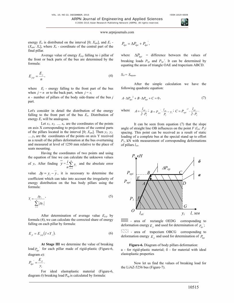
At Stage III we determine the value of breaking
load 'kpiP for each pillar made of rigid-plastic (Figure-6,
diagram а):
i
jikpi y
EP ' .
For ideal elastoplastic material (Figure-6, diagram б) breaking load Ркр is calculated by formula:
'kpikpikpi PPP ,
where kpiP = difference between the values of
breaking loads Ркр and Ркр’. It can be determined by equating the areas of triangle ОАЕ and trapezium АВСD. S = Sтрап.
After the simple calculation we have the following quadratic equation:
02 СPВPА kpikpi, (7)
where 1
sti
P2
lА
;
i1
sti'крi y
P
lРB ;
1
sti2'
крi P2
lРC
.
It can be seen from equation (7) that the slope
angle of straight line ОВ influences on the point F (lsti; P1) spacing. This point can be received as a result of static loading of a complete bus at the special stand up to effort Р1, kN with measurement of corresponding deformations of pillars lsti.
- area of rectangle OEDG corresponding to
deformation energyjiE and used for determination of '
kpiP ;
- area of trapezium OBCG corresponding to deformation energy
jiE and used for determination of kpiP
Figure-6. Diagram of body pillars deformation: а - for rigid-plastic material; б - for material with ideal elastoplastic properties
Now let us find the values of breaking load for the LiAZ-5256 bus (Figure-7).
Р, кН
l, мм
Ркрi
Ркрi’
б
а
lsti yi
Р1
Ркр
А
В С
D
О
Е
F
G
VOL. 10, NO 22, DECEMBER, 2015 ISSN 1819-6608
ARPN Journal of Engineering and Applied Sciences ©2006-2015 Asian Research Publishing Network (ARPN). All rights reserved.
www.arpnjournals.com
10516
x
z
y
1990Z
0 11702 х 27103 х 41904 х 56705 х 71506 х 86307 х 101108 х 107909 х 1097510 хцтХ
8703 Н
2570Z
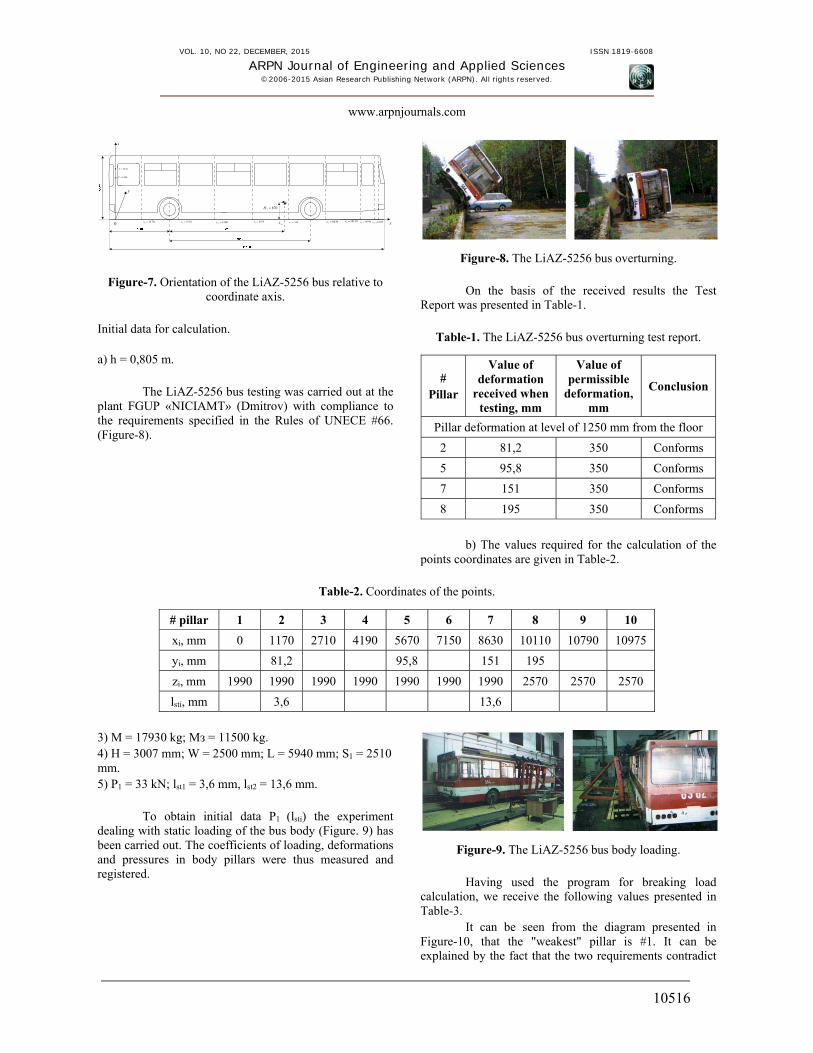
Figure-7. Orientation of the LiAZ-5256 bus relative to coordinate axis.
Initial data for calculation. a) h = 0,805 m.
The LiAZ-5256 bus testing was carried out at the plant FGUP «NICIAMT» (Dmitrov) with compliance to the requirements specified in the Rules of UNECE #66. (Figure-8).
Figure-8. The LiAZ-5256 bus overturning. On the basis of the received results the Test
Report was presented in Table-1.
Table-1. The LiAZ-5256 bus overturning test report.
# Pillar
Value of deformation
received when testing, mm
Value of permissible
deformation, mm
Conclusion
Pillar deformation at level of 1250 mm from the floor
2 81,2 350 Conforms
5 95,8 350 Conforms
7 151 350 Conforms
8 195 350 Conforms
b) The values required for the calculation of the
points coordinates are given in Table-2.
Table-2. Coordinates of the points.
# pillar 1 2 3 4 5 6 7 8 9 10
xi, mm 0 1170 2710 4190 5670 7150 8630 10110 10790 10975
yi, mm 81,2 95,8 151 195
zi, mm 1990 1990 1990 1990 1990 1990 1990 2570 2570 2570
lsti, mm 3,6 13,6
3) М = 17930 kg; Мз = 11500 kg. 4) Н = 3007 mm; W = 2500 mm; L = 5940 mm; S1 = 2510 mm. 5) Р1 = 33 kN; lst1 = 3,6 mm, lst2 = 13,6 mm.
To obtain initial data Р1 (lsti) the experiment dealing with static loading of the bus body (Figure. 9) has been carried out. The coefficients of loading, deformations and pressures in body pillars were thus measured and registered.
Figure-9. The LiAZ-5256 bus body loading.
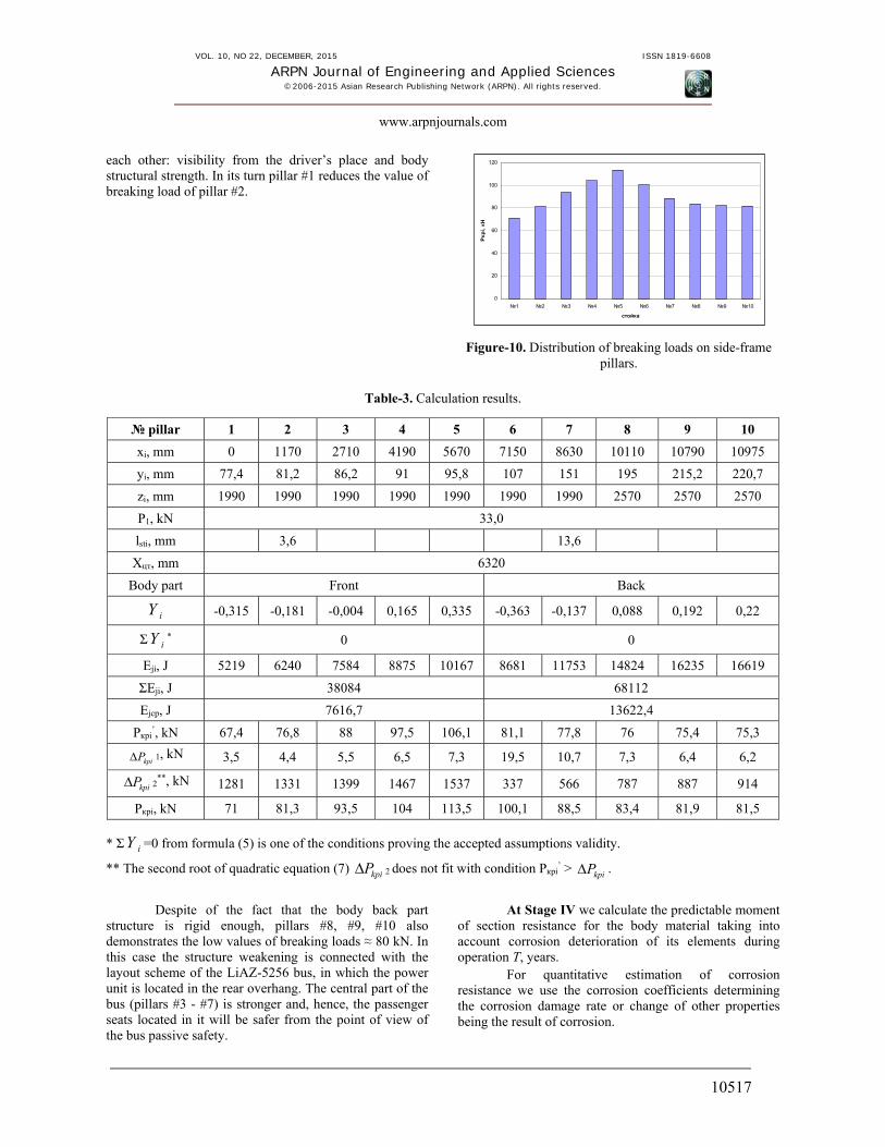
Having used the program for breaking load calculation, we receive the following values presented in Table-3.
It can be seen from the diagram presented in Figure-10, that the "weakest" pillar is #1. It can be explained by the fact that the two requirements contradict
VOL. 10, NO 22, DECEMBER, 2015 ISSN 1819-6608
ARPN Journal of Engineering and Applied Sciences ©2006-2015 Asian Research Publishing Network (ARPN). All rights reserved.
www.arpnjournals.com
10517
each other: visibility from the driver’s place and body structural strength. In its turn pillar #1 reduces the value of breaking load of pillar #2.
Figure-10. Distribution of breaking loads on side-frame pillars.
Table-3. Calculation results.
№ pillar 1 2 3 4 5 6 7 8 9 10
xi, mm 0 1170 2710 4190 5670 7150 8630 10110 10790 10975
yi, mm 77,4 81,2 86,2 91 95,8 107 151 195 215,2 220,7
zi, mm 1990 1990 1990 1990 1990 1990 1990 2570 2570 2570
Р1, kN 33,0
lsti, mm 3,6 13,6
Xцт, mm 6320
Body part Front Back
iY -0,315 -0,181 -0,004 0,165 0,335 -0,363 -0,137 0,088 0,192 0,22
Σ iY * 0 0
Еji, J 5219 6240 7584 8875 10167 8681 11753 14824 16235 16619
ΣЕji, J 38084 68112
Еjср, J 7616,7 13622,4
Ркрi’, kN 67,4 76,8 88 97,5 106,1 81,1 77,8 76 75,4 75,3
kpiP 1, kN 3,5 4,4 5,5 6,5 7,3 19,5 10,7 7,3 6,4 6,2
kpiP 2**, kN 1281 1331 1399 1467 1537 337 566 787 887 914
Ркрi, kN 71 81,3 93,5 104 113,5 100,1 88,5 83,4 81,9 81,5
* Σ iY =0 from formula (5) is one of the conditions proving the accepted assumptions validity.
** The second root of quadratic equation (7) kpiP 2 does not fit with condition Ркрi’ > kpiP .
Despite of the fact that the body back part
structure is rigid enough, pillars #8, #9, #10 also demonstrates the low values of breaking loads ≈ 80 kN. In this case the structure weakening is connected with the layout scheme of the LiAZ-5256 bus, in which the power unit is located in the rear overhang. The central part of the bus (pillars #3 - #7) is stronger and, hence, the passenger seats located in it will be safer from the point of view of the bus passive safety.
At Stage IV we calculate the predictable moment of section resistance for the body material taking into account corrosion deterioration of its elements during operation Т, years.
For quantitative estimation of corrosion resistance we use the corrosion coefficients determining the corrosion damage rate or change of other properties being the result of corrosion.
0
20
40
60
80
100
120
№1 №2 №3 №4 №5 №6 №7 №8 №9 №10
стойка
Ркр
i, кН

VOL. 10, NO 22, DECEMBER, 2015 ISSN 1819-6608
ARPN Journal of Engineering and Applied Sciences ©2006-2015 Asian Research Publishing Network (ARPN). All rights reserved.
www.arpnjournals.com
10518
Corrosion rate can be determined by studying the dependence of change of any chosen coefficient of the process in time [15]. COEFFICIENT = f (τ). (8)
True or instant differential rate of corrosion at the moment of time τ1 is equal to the first derivative of the value of coefficient (у) from time, i.e. ду/дτ when τ = τ1. In practice the average integrated rate of the process in time τ, i.e. Δу / Δτ is determined more frequently. Gas corrosion rate is more frequently expressed via the oxide film growth rate:
ddhv / , (9) where v = rate of the process;
h = oxide film thickness; τ = time of the process.
Corrosion indices include focal, deep, mass,
volume, mechanical, electric, metal susceptibility to corrosion. Сorrosion depth index k, mm/year, is most often used in the process of the bus body corrosion deterioration. It characterizes average or maximum depth of corrosion deterioration for a certain operation period [5]. Also we can measure the corrosion film thickness having been formed on metal in a time unit.
S
qq 2176,8k
, (10)
where q1 = metal weight before corrosion, g;
q2 = metal weight after corrosion, g;
ρ = metal density, g/cm3; S = metal surface, m2; τ = time of corrosion, hour.
We determined the coefficients of loss of the
metal thickness in the pillars of the framework for the bottom part of interwindow openings using the data of the researches of fatigue-and-corrosive destruction of the body surfaces of 45 buses [16] which are operated in the territory of Rostov Region (Table-4). If we assume that corrosion deterioration process of the bus body elements continues at rate k = 0, 07 mm/year (data of experimental observations), we will be able to describe the changes of strength properties of both separate elements and the bus body as a whole.
Owing to increase of corrosion deterioration in the course of time, the sizes and the resisting moments of cross sections of the bus body pillars decrease (Figure-11). Pressures are growing and after a while the material
breaking point will be exceeded, which will cause the structural failure [17, 18]. Table-4. Average loss of metal thickness in the pillars of
framework for the bottom part of interwindow openings of the bus body.
Number of buses Average loss of metal thickness
/mm/
6 0,2-0,4
12 0,4-0,5
15 0,5-0,7
10 0,7-0,8
2 through
Thus, the maximum pressure, σ, in each element
of the bus body is supposed to be within the following limits for all the operation period, Т:
σ = Mmax/W ≤ [σи], (11) where Mmax - maximum bending moment falling to the body pillars at nondestructive testing, N·m; W - resisting moment of the element cross section exposed to the maximum bending moment, m3; [σи] - permissible pressure on the bending of the metal pillar, Pа.
Table-5. Procedure of determination of permissible resisting moment of the body elements.
Translation of notation in Table-5. Section; Area A; Axial moment of inertia Jx; Resisting moment Wx; Inertia radius ix
Thus, throughout all service life of the bus, Т, the value of the resisting moment in each of its elements is to be in compliance with the following condition:
W ≥ [W] = Mmax / [σи], (12)
where [W] = minimum permissible value of the resisting moment of the element cross section exposed to the maximum bending moment, m3;
To determine W at a certain moment of time it is necessary to use a corrosion rate coefficient. In the process
Сечение Площадь А Осевой момент инерции Jx
Момент сопротивления Wx
Радиус инерции ix
whhbbh
12
33whhbbh
h
hbbh wh
6
33
wh
wh
hbbh
hbbh
12
33

VOL. 10, NO 22, DECEMBER, 2015 ISSN 1819-6608
ARPN Journal of Engineering and Applied Sciences ©2006-2015 Asian Research Publishing Network (ARPN). All rights reserved.
www.arpnjournals.com
10519
of deterioration there is a cross section area reduction and as consequence reduction of the resisting moments and increase of pressures.
When using box section pipes for the body pillars the worst scenario is possible. The maximum corrosion deterioration will occur on the wide part exposed to the maximum bending moment M from emergency loading, and resisting moment Wx will decrease. Therefore we will consider further reduction of the section resisting moment relative to axis x.
We know that the resisting moment of a box section is determined by the following expression:
h
hbhb wh
6
W33
x . (13)
For initial time:
0
300
300
x0 6W
h
hbhb wh
.
After operating time Т, year in i year:
i
wihiii
h
hbhb
6
W33
xi.
Taking into account that material is exposed to corrosion deterioration during all period T, the values of
wihiii hbhb ,,, can be presented as follows:
ii Trkbb 20,
ihhi Trkbb )1(20,
ii Trkhh 20,
iwwi Trkhh )1(20 ,
where k - corrosion depth rate index, k = 0,07 mm/year (was determined experimentally); r – coefficient of redistribution (irregularity) of corrosion deterioration rate of the section inner and outer surfaces,
внутр
внеш
k
kr , r = 0,9 (was determined experimentally).
)Trk2h(6
)T)r1(k2h()T)r1(k2b(
)Trk2h(6
)Trk2h()Trk2b(W
i0
3i0wi0h
i0
3i0i0
xi
.(14)
For the box section with project characteristics,
m, h0=0,08, b0=0,04, hw0=0,076, bh0=0,036 (before the start of operation) the section Wх resisting moment is equal to 0,0000097435 m3, or 9,7435 cm3.
Using formula 14 we investigate the dependence of Wх = f (T) of a box-shaped section of the bus body pillar. Diagram of dependence of the section resisting
moment on time for a box-shaped section of the bus body pillar is presented in Figure-11.
Figure-11. Diagram of dependence of the resisting moment Wх of a box-shaped section of the bus
body pillar on operating time.
Stage V. Having calculated the predictable resisting moment of section WT, remaining as a result of corrosion through the project service life Т, it is possible to determine critical deformation of each pillar of the cross section bus body lкр, mm towards residual vital space at level of 1250 mm from the floor, as well as the corresponding values of breaking loads Ркрi, kN.
Diagrams of dependences of efforts on corresponding deformations for pillars 1-5 located in the front part of the bus are presented in Figure-12. Depending on operation time, the character of dependence of deformations for each of the 5 pillars of the bus front part is determined by the diagram in Figure 13. Corresponding diagrams of dependences Р=f (l) and Т=f (l) for the bus back part (pillars 6-10) are presented in diagrams, Figures 14, 15.
Figure-12. Diagram of dependence of deformations of cross section pillars of the bus body front part on
breaking loads.
0
2
4
6
8
10
12
0 1 2 3 4 5 6 7 8 9 10 11 12 13 14 15 16 17 18 19 20T, лет
Wx,
м3*
10^6
0
10
20
30
40
50
60
70
0 100 200 300 400 500 600
l, мм
Ркр
, кН
Ркр=f(l1) Ркр=f(l2) Ркр=f(l3) Ркр=f(l4) Ркр=f(l5)

VOL. 10, NO 22, DECEMBER, 2015 ISSN 1819-6608
ARPN Journal of Engineering and Applied Sciences ©2006-2015 Asian Research Publishing Network (ARPN). All rights reserved.
www.arpnjournals.com
10520
Figure-13. Diagram of dependence of deformations of cross section pillars of the bus body front part on its
operation period.
Figure-14. Diagram of dependence of deformations of cross section pillars of the bus body back part on
breaking loads.
Figure-15. Diagram of dependence of deformations of cross section pillars of the bus body back part on its
operation period. The research results estimation.
One of the basic factors of the body resistance to various kinds of destruction (static, dynamic, fatigue, corrosion) is its durability. Therefore the achievement of the recommended optimum durability of a structure demands the choice of the proved objective factors influencing on all kinds of destruction.
Using the abovementioned diagrams of dependences of deformations of cross section pillars of the bus body front and back parts on its operation period (Figures 13, 15), it is possible to establish that the values of critical deformations towards residual vital space more than 350 mm occur in the bus body pillars 9 and 10 during the 8th or 9th year of its operation.
Comparing the results of calculations made by means of the offered method with the operating life data declared by the manufacturers, for a number of bus models (Table-6), it is possible to speak about considerable compatibility of the received results.
Table-6. Operating life declared by the manufacturers for a number of bus models.
Operating life declared by the manufacturer
KAVZ 4235-31(32)
PAZ-4234
PAZ-32053
PAZ-32054
LiAZ-5256 city bus
GolAZ-LiAZ-5256 transit bus
Engine life – 400000 km
600000 km
600000 km
700000 km
–
Gear box/axle life – 400000 km
600000 km
600000 km
500000 km
–
Body life 10 years
8 years 6 years 6 years 12 years
10 years
The received method of calculation of the bus
service life limit determines the value of time (years) or mileage (km). Having passed these limits the bus body strength will not meet requirements of Technical Regulations about vehicles safety [6]. The method can be used for the development of the program on «…
reasonability of introduction of service life limits for commercial vehicles and application of the preventive measures for their infringement». The expediency of the program was formulated following the results of the meeting about the measures on the Russian automobile
0
2
4
6
8
10
12
14
16
18
20
0 100 200 300 400 500 600
l, мм
Т, лет
Т=f(l1) Т=f(l2) Т=f(l3) Т=f(l4) Т=f(l5)
0
10
20
30
40
50
60
70
0 100 200 300 400 500 600 700 800 900
l, мм
Ркр
, кН
Ркр=f(l6) Ркр=f(l7) Ркр=f(l8) Ркр=f(l9) Ркр=f(l10)
0
2
4
6
8
10
12
14
16
18
20
0 100 200 300 400 500 600 700 800 900
l, мм
Т, лет
Т=f(l6) Т=f(l7) Т=f(l8) Т=f(l9) Т=f(l10)

VOL. 10, NO 22, DECEMBER, 2015 ISSN 1819-6608
ARPN Journal of Engineering and Applied Sciences ©2006-2015 Asian Research Publishing Network (ARPN). All rights reserved.
www.arpnjournals.com
10521
market support, which took place on December, 10th, 2014.
REFERENCES [1] Svedeniya о pokazatelyah sostoyanii bezopasnosti
dorozhnogo dvizheniya / Rezhim dostupa: http://www.gibdd.ru/stat/ (dustup svobodniy) - Zagl. s ekrana. [In Russian]
[2] GOST R 41.66-00 (Pravila ЕEК ООN № 66) Edinoobrazniye predpisaniya, kasayushiesya ofitsialnogo utverzhdeniya krupnogabaritnih passazhirskih transportnih sredstv v otnoshenii prochnosti verhney chasti konstruktsii. Vved. 26 maya 1999 № 184-st. М.: IPК Izdatelstvo standartov, 2000. 19 pp. [In Russian]
[3] Gepner B., C. Bojanowski, L. Kwasniewski and J. Wekezer. 2014. Effectiveness of ECE R66 and FMVSS 220 standards in rollover crashworthiness assessment of paratransit buses. International Journal of Automotive Technology. 15(4): 581-591.
[4] Ovchinnikov N.А. 2011. Eksperimentalnoye opredelenie porchnisti stoek kuzova avtobusa / Perspektiva: Materiali Mezhdunarodnoi konferentsii studentov, aspirantov i molodih uchyonih. Т. III. Nalchik: Кab.-Bаlk. Universitet. pp. 91-95. [In Russian].
[5] Kalmikov B.Yu. 2007. Avtobusi. Passivnaya bezopasnost. Momografia / B. Yu. Kalmikov, V. V. Deryushev, N. А. Ovchinnikiv; Yuzhno-Rossiyskiy gos. universitet economiki i servisa, Rostovskaya akademia Servisa (Fil.). Rostov-na-Donu. [In Russian].
[6] Postanovleniye Rossiyskoy Federatsii ot 10 sentyabrya 2009 g. №720 «Ob utverzhdenii tehnicheskogo reglamenta o bezopasnosti kolyosnih transportnih sredstv» / Rossiyskaya gazeta: setevaya versia. 2010. URL: http://www.rg.ru/2009/09/23/avto-reglament-dok.html. [In Russian].
[7] Li Z., Y. Xiao, W. Zhu, H. Zhao. 2013. The safety of body structure and occupant protection research of medium bus under three kinds of frontal impact forms. Volume 197 Lecture Notes in Electrical Engineering. 9: 279-292. Code 99825.
[8] Jeyakumar P.D., G. Devaradjane. 2012. Improvement of the frontal structure of a bus for crash accidents. ASME International Mechanical Engineering Congress and Exposition, Proceedings (IMECE). 11: 183-187. Code 100737.
[9] Orlov L.N. 2005. Passivnaya bezopasnost i prochnost kuzovov, kabin avtotransportnih sredstv. Metodi reschyota i otsenki: учеб.пособие. / NGTU. N. Novgorod, p. 230. [In Russian]
[10] Shkurkin D., Novikov V., Kobersy I., Kobersy I. and Borisova A. 2015. Investigation of the Scope of Intellectual Services in the Aspect of Virtualization and Information Economy of Modern Russia, Mediterranean Journal Of Social Sciences, 6 (5S3): 217-224.
[11] Karliński J., M. Ptak, P. Dzialak, E. Rusiński. 2014. Strength analysis of bus superstructure according to Regulation No. 66 of UN/ECE. Archives of Civil and Mechanical Engineering. 14(3): 342-353.
[12] Prokopov А.Yu. and B.Yu. Kalmikov. 2014. Metod raspredeleniya potentsialnoy energii po nesutschim elementam kuzova avtobusa pri ego oprokidivanii. Nauchnoye obozreniye. №12, ch.1. p. 216 [In Russian].
[13] Prokopov А.Yu. and B. Yu. Kalmikov. 2014 Metod opredeleniya razrushayutschih nagruzok nesutschih elementov po enegroyomkosti kuzova avtobusa i deformatsii stoek bokovini. Nauchnoye obozreniye. №11, ch.2. p. 419 [In Russian].
[14] Kalmikov B.Yu., I.Yu. Visotskii and N.А. Ovchinnikov. 2012. Ustroistvo dlya povisheniya bezopasnosti konstructsii avtobusa pri oprokidivanii. Izvestiya visshih uchebnih zavedeniy. Severo-Kavkazskiy region. Seriya: Tehnicheskiye nauki. № 5. 59-65 pp. [In Russian].
[15] Semyonova I.V., G.М. Floriantovich and А. V. Horoshilov. 2002. Korrozia i zatschita ot korrozii/ Pod red. I. V. Semyonovoi. М.: FIZMATLIT, p. 336. [In Russian]
[16] Ovchnnikov N.А. and I.V. Surzhik. 2014. Otsenka vliyaniya korrozionno-ustalostnogo rasrusheniya na prochnost kuzovov avtobusov marki PAZ-3205/ Nauka i innovatsii инновации v oblasti servisa avtotransportnih sredstv i obespecheniya bezopasnosti

VOL. 10, NO 22, DECEMBER, 2015 ISSN 1819-6608
ARPN Journal of Engineering and Applied Sciences ©2006-2015 Asian Research Publishing Network (ARPN). All rights reserved.
www.arpnjournals.com
10522
dorozhnogo dvizheniya = Science and innovations in the field of vehicle service and traffic safety : mezhdunarodniy sbornik nauchnih trudov. - Shakhti: ISOiP (filial) DGTU, 100-102pp. [In Russian].
[17] Ovchnnikov N.А., Eksperimentalnoye opredeleniye prochnosti stoek kuzova avtobusa / Perspektiva -2011: Materiali nauchnoy konfeerentsii studentov, aspirantov i molodih uchyonih. - Т. III. - Nalchik: Кab.-Bаlk. universitet, pp. 91-95. - [In Russian].
[18] Ovchnnikov N.А. 2013. Konechno-elementnii analiz napryazhonno-deformirovannogo sostoyaniya elementov poperechnih silovih secheniy kuzova avtobusa v ekspluatatsii. Inzhenerniy vestnik Dona. Т. 25. № 2 (25): 9 - [In Russian].
[19] Wang R., X.-Y. Zhang, H. Feng, J.-G. Chen. 2014. Simulation and improvement of bus rollover against barrier. Zhendong yu Chongji/Journal of Vibration and Shock. 33(6): 40-43.