the emerging practice of software product line development
TRANSCRIPT
For Single Print Only
MilitaryThe COTS Technology Authority
VOLUME 2 NUMBER 3FAL L 2006
I N T H I S I S S U E :
Chris A. CiufoI n te l Xeon ULV vs . PowerPC
W W W . M I L - E M B E D D E D . C O M
OpenSystems Publishing
CUSTOM or COTS RTOS? PLUS: XMC BOARDS & MEZZANINES
EMBEDDED SYSTEMSPhysics first:
“Keep ing fas tcompany ”
Jerry Gipper
cooling techniques
Jim Turley asks: “Inventor or Patent Troll?”
Special Guest
Serial RapidIO popularity grows
How do vendors reallydevelop COTS software?
©2006 OpenSystems Publishing. Not for distribution.
For Single Print Only
For Single Print Only
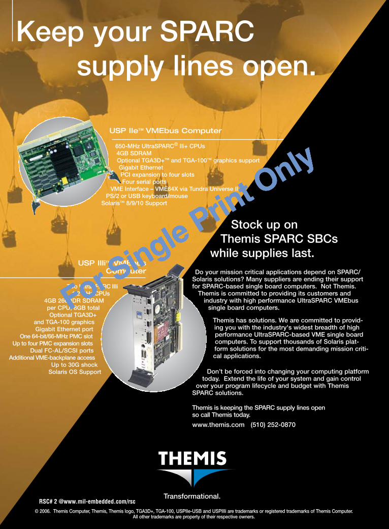
USP IIe™ VMEbus Computer
650-MHz UltraSPARC® IIi+ CPUs 4GB SDRAMOptional TGA3D+™ and TGA-100™ graphics supportGigabit EthernetPCI expansion to four slotsFour serial ports
VME Interface – VME64X via Tundra Universe IIPS/2 or USB keyboard/mouse
Solaris™ 8/9/10 Support
© 2006. Themis Computer, Themis, Themis logo, TGA3D+, TGA-100, USPIIe-USB and USPIIIi are trademarks or registered trademarks of Themis Computer. All other trademarks are property of their respective owners.
Keep your SPARC supply lines open.
Transformational.
Do your mission critical applications depend on SPARC/Solaris solutions? Many suppliers are ending their supportfor SPARC-based single board computers. Not Themis.
Themis is committed to providing its customers andindustry with high performance UltraSPARC VMEbus
single board computers.
Themis has solutions. We are committed to provid-ing you with the industry's widest breadth of highperformance UltraSPARC-based VME single boardcomputers. To support thousands of Solaris plat-form solutions for the most demanding mission criti-cal applications.
Don’t be forced into changing your computing platformtoday. Extend the life of your system and gain control
over your program lifecycle and budget with ThemisSPARC solutions.
Themis is keeping the SPARC supply lines open so call Themis today.
www.themis.com (510) 252-0870
Stock up on Themis SPARC SBCs
while supplies last. USP IIIi™ VMEbus
Computer
Two UltraSPARC IIIi 1.2 GHz CPUs
4GB 266DDR SDRAM per CPU, 8GB totalOptional TGA3D+
and TGA-100 graphicsGigabit Ethernet port
One 64-bit/66-MHz PMC slotUp to four PMC expansion slots
Dual FC-AL/SCSI portsAdditional VME-backplane access
Up to 30G shockSolaris OS Support
RSC# � @www.mil-embedded.com/rsc
©2006 OpenSystems Publishing. Not for distribution.
For Single Print Only

For Single Print Only
USP IIe™ VMEbus Computer
650-MHz UltraSPARC® IIi+ CPUs 4GB SDRAMOptional TGA3D+™ and TGA-100™ graphics supportGigabit EthernetPCI expansion to four slotsFour serial ports
VME Interface – VME64X via Tundra Universe IIPS/2 or USB keyboard/mouse
Solaris™ 8/9/10 Support
© 2006. Themis Computer, Themis, Themis logo, TGA3D+, TGA-100, USPIIe-USB and USPIIIi are trademarks or registered trademarks of Themis Computer. All other trademarks are property of their respective owners.
Keep your SPARC supply lines open.
Transformational.
Do your mission critical applications depend on SPARC/Solaris solutions? Many suppliers are ending their supportfor SPARC-based single board computers. Not Themis.
Themis is committed to providing its customers andindustry with high performance UltraSPARC VMEbus
single board computers.
Themis has solutions. We are committed to provid-ing you with the industry's widest breadth of highperformance UltraSPARC-based VME single boardcomputers. To support thousands of Solaris plat-form solutions for the most demanding mission criti-cal applications.
Don’t be forced into changing your computing platformtoday. Extend the life of your system and gain control
over your program lifecycle and budget with ThemisSPARC solutions.
Themis is keeping the SPARC supply lines open so call Themis today.
www.themis.com (510) 252-0870
Stock up on Themis SPARC SBCs
while supplies last. USP IIIi™ VMEbus
Computer
Two UltraSPARC IIIi 1.2 GHz CPUs
4GB 266DDR SDRAM per CPU, 8GB totalOptional TGA3D+
and TGA-100 graphicsGigabit Ethernet port
One 64-bit/66-MHz PMC slotUp to four PMC expansion slots
Dual FC-AL/SCSI portsAdditional VME-backplane access
Up to 30G shockSolaris OS Support
RSC# � @www.mil-embedded.com/rsc
MicroTCA communications servers use a revolutionary system architecture to meet the military’sbudget requirements and work within an open architecture computing environment. Motorola is recognized for itskey role in ushering in this innovative technology. Backed by Arrow’s broad line card, technical expertise, services,outstanding integration capabilities, and supply chain solutions, MicroTCA technology reduces the time required todeploy and refresh systems.
Offering the economies of commercial off-the-shelf products andthe flexibility of custom solutions, MicroTCA technology co-existswith VME and extends the life of previous investments through:
• Adherence to standards-based open architecture systems requirements• Very compact form factor• Superior chassis flexibility• Compute density and scalability• Hot-swappable Advanced Mezzanine Cards• A common base platform and associated cost savings
Arrow and Motorola—Defining the New Era in Defense and Aerospace Efficiency
Development units available.Call 888-427-2250 or visit www.arrownac.com/NotAPassingTrend to learnwhy MicroTCA technology is destined to influence embedded computing for along time to come. Quantities are limited, so call now!
©2006 Arrow Electronics, Inc. Arrow and the Arrow logo are registered trademarks; MOTOROLA and the Stylized M Logo are registered in the US Patent & Trademark Office.PICMG and the PICMG logo are registered trademarks, and MicroTCA is a trademark of the PCI Industrial Computer Manufacturers Group.
Back in 1981, while people were busy spinningon their heads, Motorola launched VME and left the embedded computing competition flat on its back.
Now, 25 years later, Arrow Electronics and Motorola are definingthe new era in embedded computing with MicroTCA™ solutions.
20
06
19
81
MicroTCA™ technology has the flexibility to meet your needs as time goes by.
www.arrownac.com/NotAPassingTrend | 888.427.2250MicroTCA technology. Not a passing trend. RSC# � @www.mil-embedded.com/rsc©2006 OpenSystems Publishing. Not for distribution.
For Single Print Only
For Single Print Only
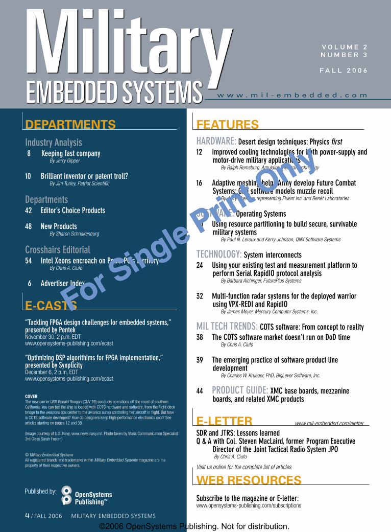
w w w . m i l - e m b e d d e d . c o mEMBEDDED SYSTEMSMilitaryDEPARTMENTSIndustry Analysis 8 Keeping fast company
ByJerryGipper
10 Brilliant inventor or patent troll? ByJimTurley,PatriotScientific
Departments42 Editor’s Choice Products
48 New Products BySharonSchnakenburg
Crosshairs Editorial54 Intel Xeons encroach on PowerPC’s territory
ByChrisA.Ciufo
6 Advertiser Index
E-cASTS“Tackling FPGA design challenges for embedded systems,” presented by PentekNovember 30, 2 p.m. EDT www.opensystems-publishing.com/ecast
“Optimizing DSP algorithims for FPGA implementation,” presented by SynplicityDecember 6, 2 p.m. EDT www.opensystems-publishing.com/ecast
COVERThe new carrier USS Ronald Reagan (CNV 76) conducts operations off the coast of southern California. You can bet the ship is loaded with COTS hardware and software, from the flight deck bridge to the weapons ops center to the avionics suites controlling her aircraft in flight. But how is COTS software developed? How do designers keep high-performance electronics cool? See articles starting on pages 12 and 38.
(Image courtesy of U.S. Navy, www.news.navy.mil. Photo taken by Mass Communication Specialist 3rd Class Sarah Foster.)
© MilitaryEmbeddedSystemsAll registered brands and trademarks within MilitaryEmbeddedSystems magazine are the property of their respective owners.
FEATURESHARDWARE: Desert design techniques: Physics first12 Improved cooling technologies for both power-supply and
motor-drive military applications ByRalphRemsburg,AmulaireThermalTechnology
16 Adaptive meshing helps Army develop Future Combat Systems: CFD software models muzzle recoil ByJerryFireman,representingFluentInc.andBenétLaboratories
SOFTWARE: Operating Systems20 Using resource partitioning to build secure, survivable
military systems ByPaulN.LerouxandKerryJohnson,QNXSoftwareSystems
TECHNOLOGY: System interconnects24 Using your existing test and measurement platform to
perform Serial RapidIO protocol analysis ByBarbaraAichinger,FuturePlusSystems
32 Multi-function radar systems for the deployed warrior using VPX-REDI and RapidIO ByJamesMeyer,MercuryComputerSystems,Inc.
MIL TECH TRENDS: COTS software: From concept to reality38 The COTS software market doesn’t run on DoD time
ByChrisA.Ciufo
39 The emerging practice of software product line development ByCharlesW.Krueger,PhD,BigLeverSoftware,Inc.
44 PRODUCT GUIDE: XMC base boards, mezzanine boards, and related XMC products
E-LETTER www.mil-embedded.com/eletter
SDR and JTRS: Lessons learned Q & A with Col. Steven MacLaird, former Program Executive
Director of the Joint Tactical Radio System JPOByChrisA.Ciufo
Visitusonlineforthecompletelistofarticles
WEB RESOURcESSubscribe to the magazine or E-letter:www.opensystems-publishing.com/subscriptions
Published by:
V O L U M E 2N U M B E R 3
F a L L 2 0 0 6
� / FALL 2006 MiLitAry EMBEDDED SyStEMS
©2006 OpenSystems Publishing. Not for distribution.
For Single Print Only

For Single Print Only
Copyright ©2006, Intel Corporation. All rights reserved. Intel and the Intel logo are trademarks or registered trademarks of Intel Corporation or its subsidiaries in the United States and other countries.
The Critical Path to Transformation
The Intel platform approach puts you on the critical path to transformation. The objective: deliver the most advanced, cost-effective solutions to your customers. The roadmap: multi-core processors and platform technologies from Intel complemented by a broad array of standards-based solutions from its ecosystem. The deliverables: scalable, power ef cient processing for new generations of embedded applications.
The results: next generation features, reduced development time and investment. The time: now.
www.intel.com/go/military
MTC_ad_Mar'06_1a.indd 1 3/3/06 11:46:31 AM
RSC# � @www.mil-embedded.com/rsc©2006 OpenSystems Publishing. Not for distribution.
For Single Print Only
For Single Print Only
RSC# � @www.mil-embedded.com/rsc
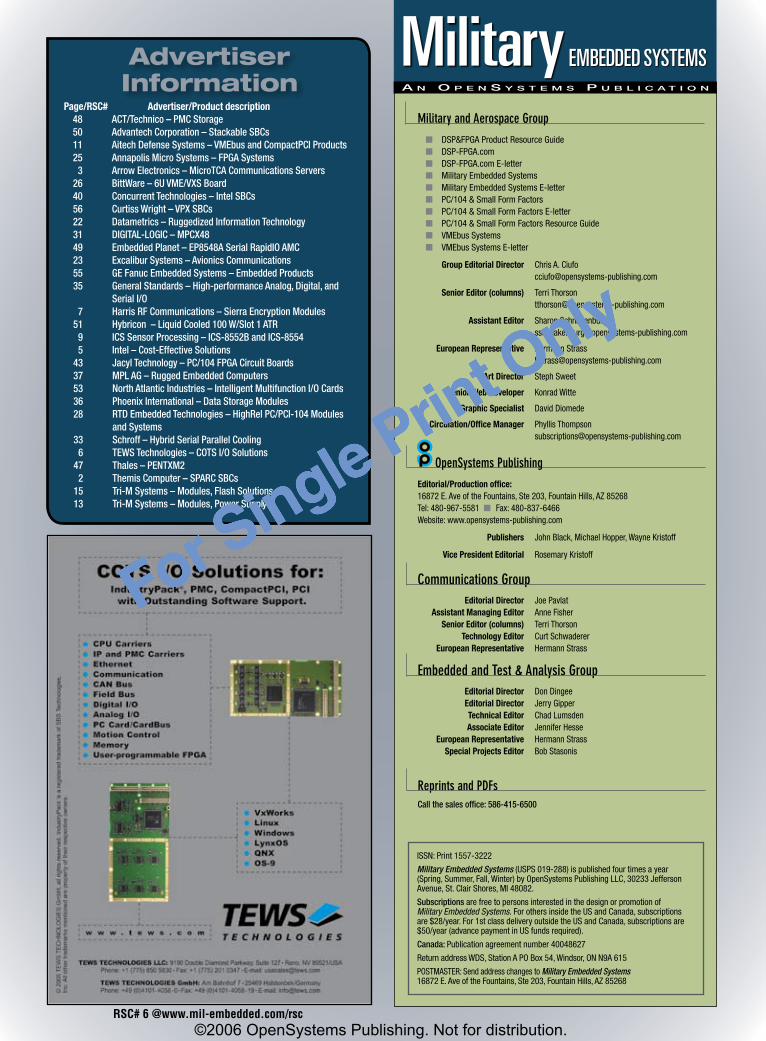
Page/RSC# Advertiser/Productdescription 48 ACT/Technico–PMCStorage 50 AdvantechCorporation–StackableSBCs 11 AitechDefenseSystems–VMEbusandCompactPCIProducts 25 AnnapolisMicroSystems–FPGASystems 3 ArrowElectronics–MicroTCACommunicationsServers 26 BittWare–6UVME/VXSBoard 40 ConcurrentTechnologies–IntelSBCs 56 CurtissWright–VPXSBCs 22 Datametrics–RuggedizedInformationTechnology 31 DIGITAL-LOGIC–MPCX48 49 EmbeddedPlanet–EP8548ASerialRapidIOAMC 23 ExcaliburSystems–AvionicsCommunications 55 GEFanucEmbeddedSystems–EmbeddedProducts 35 GeneralStandards–High-performanceAnalog,Digital,and
SerialI/O 7 HarrisRFCommunications–SierraEncryptionModules 51 Hybricon–LiquidCooled100W/Slot1ATR 9 ICSSensorProcessing–ICS-8552BandICS-8554 5 Intel–Cost-EffectiveSolutions 43 JacylTechnology–PC/104FPGACircuitBoards 37 MPLAG–RuggedEmbeddedComputers 53 NorthAtlanticIndustries–IntelligentMultifunctionI/OCards 36 PhoenixInternational–DataStorageModules 28 RTDEmbeddedTechnologies–HighRelPC/PCI-104Modules
andSystems 33 Schroff–HybridSerialParallelCooling 6 TEWSTechnologies–COTSI/OSolutions 47 Thales–PENTXM2 2 ThemisComputer–SPARCSBCs 15 Tri-MSystems–Modules,FlashSolutions 13 Tri-MSystems–Modules,PowerSupply
AdvertiserInformation A n O p e n S y S t e m S p u b l i c A t i O n
Military and Aerospace Group
n DSP&FPGAProductResourceGuide n DSP-FPGA.com n DSP-FPGA.comE-letter n MilitaryEmbeddedSystems n MilitaryEmbeddedSystemsE-letter n PC/104&SmallFormFactors n PC/104&SmallFormFactorsE-letter n PC/104&SmallFormFactorsResourceGuide n VMEbusSystems n VMEbusSystemsE-letter
GroupEditorialDirector ChrisA.Ciufo [email protected]
SeniorEditor(columns) TerriThorson [email protected]
AssistantEditor SharonSchnakenburg [email protected]
EuropeanRepresentative HermannStrass [email protected]
ArtDirector StephSweet
SeniorWebDeveloper KonradWitte
GraphicSpecialist DavidDiomede
Circulation/OfficeManager PhyllisThompson [email protected]
OpenSystems Publishing
Editorial/Productionoffice:16872E.AveoftheFountains,Ste203,FountainHills,AZ85268Tel:480-967-5581nFax:480-837-6466Website:www.opensystems-publishing.com
Publishers JohnBlack,MichaelHopper,WayneKristoff
VicePresidentEditorial RosemaryKristoff
Communications Group EditorialDirector JoePavlat AssistantManagingEditor AnneFisher SeniorEditor(columns) TerriThorson TechnologyEditor CurtSchwaderer EuropeanRepresentative HermannStrass
Embedded and Test & Analysis Group EditorialDirector DonDingee EditorialDirector JerryGipper TechnicalEditor ChadLumsden AssociateEditor JenniferHesse EuropeanRepresentative HermannStrass SpecialProjectsEditor BobStasonis
Reprints and PDFsCallthesalesoffice:586-415-6500
OpenSystemsPublishing™
EMBEDDED SYSTEMSMilitary
ISSN:Print1557-3222
Military Embedded Systems(USPS019-288)ispublishedfourtimesayear(Spring,Summer,Fall,Winter)byOpenSystemsPublishingLLC,30233JeffersonAvenue,St.ClairShores,MI48082.
SubscriptionsarefreetopersonsinterestedinthedesignorpromotionofMilitary Embedded Systems. ForothersinsidetheUSandCanada,subscriptionsare$28/year.For1stclassdeliveryoutsidetheUSandCanada,subscriptionsare$50/year(advancepaymentinUSfundsrequired).
Canada:Publicationagreementnumber40048627
ReturnaddressWDS,StationAPOBox54,Windsor,ONN9A615
POSTMASTER:SendaddresschangestoMilitary Embedded Systems16872E.AveoftheFountains,Ste203,FountainHills,AZ85268
©2006 OpenSystems Publishing. Not for distribution.
For Single Print Only
For Single Print Only
SEC
-2
Members of the Sierra™ family of encryption modules are easily integratedinto communications devices of all kinds.Sierra encrypts classified information,processes data at a higher speed, is extremely power efficient, and allowsmodules to be reprogrammed as missions change.
It's benefits like these that led the U.S. Department of Defense to selectSierra II for one of the most importantcommunications programs in recent history. Sierra II has been chosen to encrypt 100 percent of the radiosunder Cluster 1 of the U.S. Joint TacticalRadio System program.
Take a closer look at your encryption.
Are you gettingthe protection you need?
www.harris.com
R F C o m m u n i c a t i o n s•
G o v e r n m e n t•
B r o a d c a s t•
M i c r o w a v e
assuredcommunications™
Harris-SECad-MilEmbSys.qxd:Layout 1 9/11/06 3:41 PM Page 1
RSC# � @www.mil-embedded.com/rsc
©2006 OpenSystems Publishing. Not for distribution.
For Single Print Only

For Single Print Only
industry Analysis
In the spring of 1981, I was in the final days of my preparation for entry into the real world. The computer labs at Iowa State University were my second home. My first introduction to card buses was the S-100 bus. I was attending demonstrations on emerging PC technology sponsored by Commodore and Radio Shack. I was reading Byte magazine when it was still in existence and less than 100 pages!
1981 was a busy year for technology. On April 12, many of us sat on the edge of our seats as we witnessed the launch of Space Shuttle Columbia. After a successful two-day mission, we also watched as it touched down on the long runway at Edwards Air Force Base. (I was in one of those ISU labs.) Since that time, the space shuttle fleet has flown 115 missions.
I also remember using free time to test out those great new video games. Who can forget Frogger, Galaga, and Donkey Kong, all introduced in 1981. I wish I would have used more of that time studying! While we were enjoying these games, we also watched a fledgling cable network – introduced August 1 – that played music on TV: MTV.
On August 12, IBM rolled out the one technology item that has probably had the biggest effect on us techies: the IBM 5150 personal computer. This beige box, with a starting price of $1,565, had a mere 16 kB of memory and used audio cassettes to load and save data. (A floppy disk drive was optional.) IBM’s press release trumpeted the screen’s “green phosphor characters for reading comfort” and “easily understood operation manuals” that made it “possible to begin using the computer within hours.”
IBM’s wasn’t the first home computer, but Commodore’s, Apple’s, and Radio Shack’s Tandy products were considered “toys.” The IBM name added credibility that brought trust to the business environment.
eTForecasts estimates 25-year sales of MS-DOS and Windows PCs based on the original IBM PC architecture:
nIn the United States: Unit shipments have totaled 580 million and represent U.S. $998 billion, August 1981 to August 2006
nWorldwide: Unit shipments have totaled 1,540 million and represent U.S. $3,100 billion, August 1981 to August 2006
The revenue figures include initial hardware sales only and exclude PC software and services. The software and services sales are probably several times these numbers!
Some of the other computer technology from 1981 that might trigger a memory or two include: the TFC 3450 by Fujitsu, the Commodore VIC-20, the Sinclair ZX81, the Osborne I (who can forget!), the TI-99/4A, the IBM System/23, the Epson HX-20, the Rockwell AIM 65/40 (I cut my teeth on assembly programming on this machine), and the Dynabyte 5100.
In an HP laboratory in Corvallis, Oregon, an Iowa farm-boy-turned-PhD (not me) was about to introduce the HP 12c Financial Calculator. After 25 years, this calculator is still sold under its original name and model.
In late 1981, after several committee meetings and after a number of other companies decided to adopt the combined standard, the NCR BYSE (Byte Serial) and SASI (Shugart Associates System Interface) was introduced under the new name “SCSI.”
With all this going on, it’s hard to imagine any other great technologies emerging from all the press releases, but it happened! On October 21 (for some reason the numbers 1 and 2 show up in a lot of these introduction dates – maybe this means something to you numerologists out there), there was a small innocuous press release issued from Brussels, Munich, and Hamburg that was to forever change the embedded computing segment of the technology world. The headline declared “Mostek, Motorola, Philips/Signetics, and Thomson CSF announce a common system bus for 16/32-bit computer systems.” Of course, they were talking about VMEbus.
The announcing companies were claiming that this technology would be great for process control technology, data technology, intelligent terminals, and digital communication networks.
VMEbus is in some great company. It is a technology that has great staying power, has adapted to the changing needs of its users, and has embraced change as it matures. VMEbus has aged very well. I look forward to the changes that are ahead in the next 25 years.
VMEbus, happy anniversary!
For more information, contact Jerry Gipper at [email protected].
OR CALL TOLL FREE (US ONLY)
800-368-2738 or 703-263-1483CHECK THE FULL SPEC NOW AT
www.ics-ltd.com/8554www.ics-ltd.com/8552B
Photo Courtesy of U.S. Army
Delivering the best solution means not making compromises. Not compromising performance – whenyou could have the industry-leading sustained performance of the ICS-8552B or ICS-8554. Not compromisingreliability – when you could have the world-beating expertise of ICS in developing rugged solutions. Not compromising choice – when the ICS-8552B and ICS-8554 provide the best in ADC, DDC and FPGA technology forsoftware defined radio, military communications, radar and signal intelligence applications. And not compromisingyour budget when you can choose the optimum solution for either development or deployment.
Or is second best good enough?
Leading the way in Digital Receiver TechnologyWhen only the best is good enough.
ICS-8552B
ICS-8554
ICS_8554-ICS_8552B 1/11/06 10:15 Page 1
By Jerry Gipper
Keeping fast company
� / FALL 2006 MiLitAry EMBEDDED SyStEMS
©2006 OpenSystems Publishing. Not for distribution.
For Single Print Only
For Single Print Only
OR CALL TOLL FREE (US ONLY)
800-368-2738 or 703-263-1483CHECK THE FULL SPEC NOW AT
www.ics-ltd.com/8554www.ics-ltd.com/8552B
Photo Courtesy of U.S. Army
Delivering the best solution means not making compromises. Not compromising performance – whenyou could have the industry-leading sustained performance of the ICS-8552B or ICS-8554. Not compromisingreliability – when you could have the world-beating expertise of ICS in developing rugged solutions. Not compromising choice – when the ICS-8552B and ICS-8554 provide the best in ADC, DDC and FPGA technology forsoftware defined radio, military communications, radar and signal intelligence applications. And not compromisingyour budget when you can choose the optimum solution for either development or deployment.
Or is second best good enough?
Leading the way in Digital Receiver TechnologyWhen only the best is good enough.
ICS-8552B
ICS-8554
ICS_8554-ICS_8552B 1/11/06 10:15 Page 1
RSC# � @www.mil-embedded.com/rsc©2006 OpenSystems Publishing. Not for distribution.
For Single Print Only
For Single Print Only
By Jim Turley
industry Analysis
Software is a lot like prostitution. You get to sell it, then sell the same thing again to someone else. It’s a service industry. There’s no inventory, no cost of goods, and no manufacturing problems. It’s labor-intensive. There’s very little overhead, and the profit margin approaches 100 percent. The product, unfortunately, depreciates rapidly with age. And yet, like the world’s oldest profession, hardly anyone in the software business – with a few notable exceptions – ever gets rich at it.
Despite all these similarities, most people like software companies (again, with one or two exceptions). We look favorably upon the software industry as a beneficial and valuable part of the high-tech community. Nobody seeks to ban software or make it illegal, or to rein in software development or progress. On the contrary, we’re training new programmers here and in other countries at a fantastic clip. We want more, please.
Even though there’s only a thin line separating these two business models, nobody seems to confuse prostitutes with programmers. We instinctively know the difference between hookers and coders, between women of ill repute and techies of questionable hygiene.
Patents and copyrights are a lot like software, too. There’s no tangible product there, but we still know there’s real value. We applaud inventors like Thomas Edison for his creative genius and his patented inventions, even though he never actually mass-produced anything. All the light bulbs, phonographs, and what-not were built by other companies under license.
Edison would be less revered if he’d kept all his inventions to himself, hoarding the patents and preventing anyone from making commercial use of them. What good is an invention if no one gets to use it? The whole point of a patent is to promote commercial exploitation; you’re supposed to share it. Otherwise it’s called a trade secret (like the recipe to Diet Coke).
It’s good to share, as we learned in grade school. In the high-tech world, it’s also profitable. Companies with interesting inventions are encouraged to patent and therefore share them. Companies that can’t – or don’t wish to – manufacture products can still participate a little in the success of the products they invented.
Of course, there’s always some risk with sharing. Someone might want to steal your property (intellectual or otherwise) and use it for free. In high-tech patent suits, as in some European soccer games, there’s a tendency for one party to fall down and cry “patent troll,” shedding alligator tears to gain sympathy and deflect attention away from their illegal behavior.
A real patent troll is a person or company that extorts money for a patent it has no intention of using. An example would be a law firm that buys up patents for no other reason than to milk them for income. That’s a lot different from a high-tech company that’s been granted its own patents for inventions it developed that were used in its own products and offered for license. Like programmers and prostitutes, there’s a big difference between the two, but some observers still tar them both with the same brush.
Yes, Virginia, there really are patent trolls, but they’re not lurking under every high-tech bridge throughout the hardware and software landscape. Just because a company enforces its patent rights doesn’t make it a patent troll or a bad guy. Jeer at the law firms if you want, but spare a cheer for the high-tech hardware and software companies that have invented things, shared them with the world, and maybe made a living from their inventions.
Jim Turley is an independent analyst covering microprocessors, embedded systems, intellectual property licensing, and semiconductors. He writes, presents, and consults with high-technology firms throughout the world. He is also a member of the board at Patriot Scientific. Jim is the author of seven books and hundreds of articles. He was previously editor-in-chief of Embedded Systems Design magazine and editor of the journal Microprocessor Report. He is frequently quoted in The Wall Street Journal, The New York Times, San Jose Mercury News, and appears on TV, radio, and Internet broadcasts. He has a stunningly attractive wife, two overachieving children, and an apparently brain-damaged dog.
For more information, contact Jim at [email protected].
Brilliant inventor or patent troll?
10 / FALL 2006 MiLitAry EMBEDDED SyStEMS
gUEst EditORiaL
©2006 OpenSystems Publishing. Not for distribution.
For Single Print Only
For Single Print Only
We can't change the physics... but we can ensure your COTS sub-systems are designed, built, and tested to perform reliably at the temperature extremes of your specification – without custom development, "work-arounds", or compromises.
We take the extra steps... including pre-screened parts qualification, HALT, and 100% HASS/ESS testing to ensure that every standard Aitech product meets all your temperature and rugged performance specifications...standard.
We've been there... Aitech subsystems have been proven in the world's most demanding mission-critical mil/aero applications – from complex ground, air and sea platforms to rad-tolerant solutions for the Space Shuttle, International Space Station and now earth orbiting satellites!
We've done that... Meeting full temperature-range specifications withstandard products is just part of our 20+ year heritage and commitment to COTS advancements – from the first conduction-cooled Mil-Spec VME board in 1984, to today's highest functionality MIPS/Watt boards, multi-Gigabyte mass Flash mass memory cards, and high-speed mezzanines.
We have the proof...Visit our web site or call for more information and our catalog of proven solutions.
Aitech continues to provide industry standard open systems architectures such as VMEbus and CompactPCI products, designed and tested to -55°C to +85°C asstandard, because you can’t bypass the rules of engagement either.
Aitech Defense Systems, Inc.9301 Oakdale Avenue Chatsworth, CA 91311 email: [email protected] Toll Free: 888-Aitech8 - (888) 248-3248 Fax: (818) 718-9787www.rugged.com
AIT-F-1375 MilEmbSys 2/20/06 4:05 PM Page 1
RSC# 11 @www.mil-embedded.com/rsc
©2006 OpenSystems Publishing. Not for distribution.
For Single Print Only
For Single Print Only
Improved cooling technologies for both power-supply and motor-drive military applicationsBy Ralph Remsburg
Power dissipation problems are requiring increasingly complex design solutions. While designs that are more efficient make thermal management possible, current chips and systems still require sophisticated methods for dissipating heat. Several different fin geometries might be used to cool a three-chip, 1,080 W Insulated Gate Bipolar Transistor (IGBT) copper cold plate. The geometries are compared using maximum junction temperature and efficiency. One manufacturing method, Metal Injection Molding (MIM), appears to meet the thermal objectives and is examined more closely.
Insulated Gate Bipolar Transistors (IGBTs) generally are used as switching components in inverter circuits in both power-supply and motor-drive military applications. Although very efficient, these modules suffer from conduction and switching-power losses, which generate heat that must be conducted away from the power chips into the environment.
Previously, familiar air-cooled aluminum heat sinks were sufficient for this heat conduction. But as some military converter and inverter circuit applications reached multi-megawatt requirements, the more thermally effective approach of liquid cooling using copper cold plates has become more common. Cold plates have been improved with more capable designs that utilize lanced-offset fins to replace serpentine-tube cold plates. However, the space constraints of shrinking cold plates – and the strict demand to lower cost – have created a need for even more efficient heat-transfer surfaces within the cold plate.
Innovative designs utilizing impingement flow paths and microchannel surfaces
are starting to be used. A manufacturing process called Model Injection Molding (MIM) makes highly efficient nonlinear fin arrays. A fin, technically referred to as an extended surface, is a protrusion from a heated surface that provides more surface area for heat dissipation. A fin array or fin pattern usually takes the form of a repeating series of identical fins with identical spacing between fins. The exact shape and spacing between fins can have a dramatic effect on the amount of heat that can be dissipated from a surface, and hence, the junction temperature of a device mounted to that surface.
Fin comparisonWhile there have been many studies of single cooling fin geometry parameters, the conclusions often conflict or can be applied only over a narrow range of variables. A review of the literature reveals that most studies of single-fin geometry neglect the importance of pressure drop, which for most real-world liquid-cooling systems is directly related to thermal performance by the pump flow curve. Even when the literature agrees on the relative performance of a single fin, these findings may become distorted when multiple, identical fin flow fields interact within a fin array.
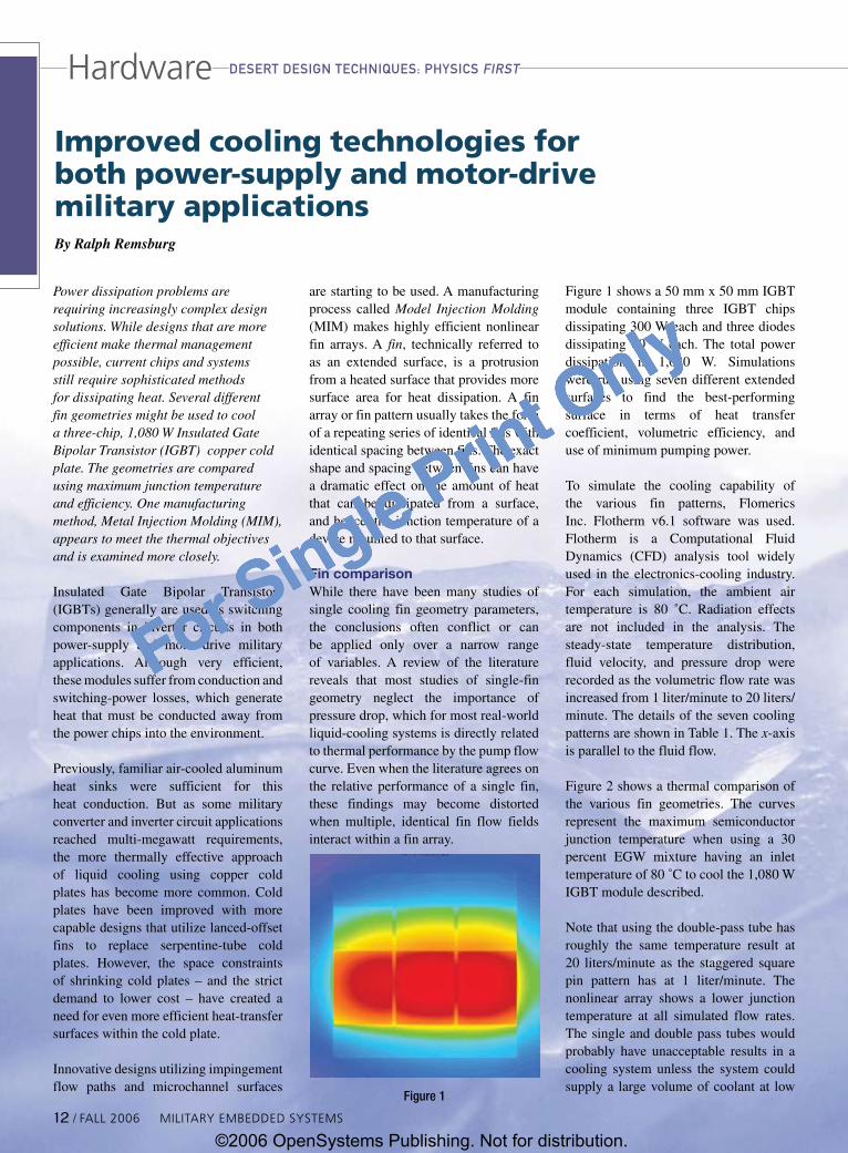
Figure 1 shows a 50 mm x 50 mm IGBT module containing three IGBT chips dissipating 300 W each and three diodes dissipating 60 W each. The total power dissipation is 1,080 W. Simulations were run using seven different extended surfaces to find the best-performing surface in terms of heat transfer coefficient, volumetric efficiency, and use of minimum pumping power.
To simulate the cooling capability of the various fin patterns, Flomerics Inc. Flotherm v6.1 software was used. Flotherm is a Computational Fluid Dynamics (CFD) analysis tool widely used in the electronics-cooling industry. For each simulation, the ambient air temperature is 80 ˚C. Radiation effects are not included in the analysis. The steady-state temperature distribution, fluid velocity, and pressure drop were recorded as the volumetric flow rate was increased from 1 liter/minute to 20 liters/minute. The details of the seven cooling patterns are shown in Table 1. The x-axis is parallel to the fluid flow.
Figure 2 shows a thermal comparison of the various fin geometries. The curves represent the maximum semiconductor junction temperature when using a 30 percent EGW mixture having an inlet temperature of 80 ˚C to cool the 1,080 W IGBT module described.
Note that using the double-pass tube has roughly the same temperature result at 20 liters/minute as the staggered square pin pattern has at 1 liter/minute. The nonlinear array shows a lower junction temperature at all simulated flow rates. The single and double pass tubes would probably have unacceptable results in a cooling system unless the system could supply a large volume of coolant at low
Figure1
Hardware
12 / FALL 2006 MiLitAry EMBEDDED SyStEMS
dEsERt dEsigN tEchNiqUEs: physics FiRst
©2006 OpenSystems Publishing. Not for distribution.
For Single Print Only

For Single Print Only
pressure. In this 1,080 W application, the nonlinear array has an 11.2 ̊ C lower junction temperature at 1 liter/minute than the next best performing geometry, which is the lanced-offset fin pattern. At 20 liters/minute, the nonlinear array maintains a 2.0 ˚C lower junction temperature.
Figure 3 shows a com-parison of pressure drop results for the simulation series.
The staggered square pins, although producing a good result in terms of temperature rise (second to the nonlinear array), have a high-pressure requirement. At 20 liters/minute, the staggered square pins have nearly 4.3x the fluid resistance as the nonlinear array.
Figure 4 shows the relative efficiency of the fin patterns when compared using a metric of θP
P, which is the
product of ˚C/W and watts of pumping power. The lower the value, the more efficient the fin pattern. As noted previously, the staggered pin pattern has
Pattern #Finsinx
#Finsiny
Diameterorthickness(mm)
Finarea(cm2)
Singletube - - 10.0 15.7
Doubletube - - 10.0 31.4
Stackedfins 49 - 0.20 245
Squarein-line 31 31 0.785 151
Squarestaggered 31 31 0.785 151
Lanced-offset 49 8 0.20x3.5 137
Nonlinear - - 0.5 135
Table1
Figure2
Figure3
100Mhz PC/104 Module
Featuring the new edition ZFx86FailSafe® Embedded PC-on-a-Chip
Dual watchdog timers, PhoenixBIOS and FAILSAFE Boot ROM
Extended temperature -40°C to 85°C
MZ104
108 Watt PC/104+ Power Supply
+3.3V, +5V, +12V & -12V DC output
6V to 40V DC input range
High Efficiency up to 95%
PC/104 compliant
Extended temperature: -40OC to +85OC
HE104+DX
PC/104 Can-Tainer
rugged anodized aluminum PC/104 enclosuredesigned for harsh environments
isolating shock mount and an internal stackvibration mount provides maximum protection
from high frequency vibrations and low frequency G-forces
CT104
1.800.665.5600www.tri-m.com [email protected]
tel: 604.945.9565 fax: 604.945.9566HEAD OFFICE: VANCOUVER
Hardware
Figure4
dEsERt dEsigN tEchNiqUEs: physics FiRst
RSC# 1� @www.mil-embedded.com/rsc
©2006 OpenSystems Publishing. Not for distribution.
For Single Print Only
For Single Print Only
Hardware
good thermal performance but a very high-pressure drop. Therefore, efficiency is low.
According to data presented in Figure 4, the best surface in terms of efficiency is the single-pass tube. Although the efficiency is high, the lack of surface area and the resulting high junction temperature may preclude the use of this type of cold plate for cooling high-power modules. The nonlinear array performs better than all the other tested configurations in terms of junction temperature and has a relatively low pressure drop and, therefore, high efficiency. Because of the high efficiency, the nonlinear array may have advantages when it’s used in low- and high-power applications.
Nonlinear fin arraysIn a nonlinear fin array, extensive CFD analysis ensures that each fin is optimized for maximum performance while simultaneously accounting for the performance flow fields of the fins adjacent to it in the array.
There are only a few processes that can economically produce a nonlinear
fin array. MIM is one of the most flexible. Using combined patented and proprietary technology to address thermal manage-ment challenges in the computing and other industries, MIM injection-molding technology was developed by Amulaire Thermal Technology.
Figure 5 shows the sequence used to make a MIM part. First, a mixture of powdered metal and polymer binders is molded into the desired shape. The part is removed from the mold and sintered at high temperatures to remove the polymer binders so that no extraneous material remains in the final product. Sintering also bonds the metal particles. During sintering, while the polymer binder debinds and vaporizes, the parts shrink in a uniform and controlled manner. Usually a net shape is achieved with no need of further processing.
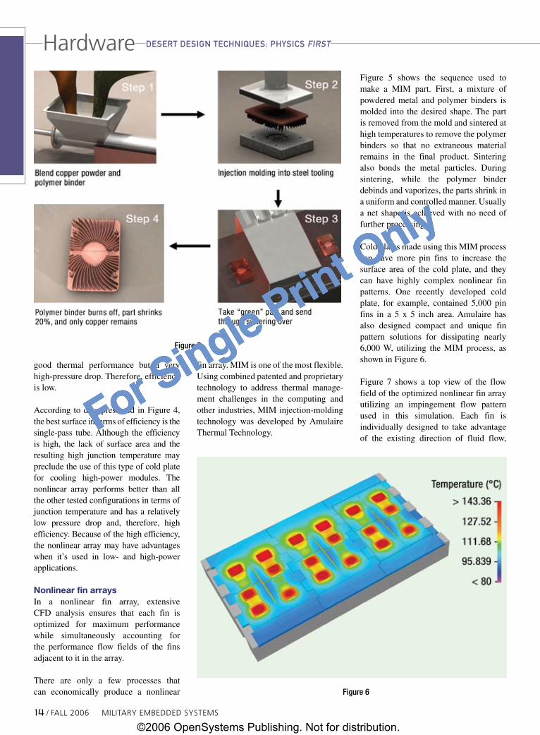
Cold plates made using this MIM process can have more pin fins to increase the surface area of the cold plate, and they can have highly complex nonlinear fin patterns. One recently developed cold plate, for example, contained 5,000 pin fins in a 5 x 5 inch area. Amulaire has also designed compact and unique fin pattern solutions for dissipating nearly 6,000 W, utilizing the MIM process, as shown in Figure 6.
Figure 7 shows a top view of the flow field of the optimized nonlinear fin array utilizing an impingement flow pattern used in this simulation. Each fin is individually designed to take advantage of the existing direction of fluid flow,
Figure5
Figure6
1� / FALL 2006 MiLitAry EMBEDDED SyStEMS
dEsERt dEsigN tEchNiqUEs: physics FiRst
©2006 OpenSystems Publishing. Not for distribution.
For Single Print Only

For Single Print Only
minimizing pressure drop while offering an optimized heat transfer surface area. The inlet coolant flow impinges at the center of the fin pattern. Round pins at the center transfer heat directly from the hottest part of the IGBT module into the fluid area of the cold plate having the highest fluid velocity and highest heat-transfer coefficient.
As the fluid moves outward from the point of impingement and the velocity decreases, the round fins change shape to ellipses to take advantage of the direction of fluid flow and offer more surface area. Although the surface area of each fin is greater in this area, the pressure drop does not increase greatly because the fluid is moving slower.
As the fluid approaches the exit ports, velocity starts to increase. Again the fins change shape, but from elliptical to round. At the same flow rate, this nonlinear design results in a significant reduction in maximum temperature from the lanced offset fin pattern of Table 1, which would be the typical choice used to cool the module. Because the objective of thermal management specialists is to eliminate problems in heat transfer at the component and system levels, these results show that a properly designed heat sink using a nonlinear fin array can make an important contribution to that goal.
Increased reliability and performanceA recently developed MIM technology enables the development of cold plates for IGBTs with superior heat-dissipation capabilities. This new approach to IGBT cold plates has implications for both
power-supply and motor-drive military applications.
As component designers work to in-crease the power capabilities of IGBT modules, it becomes more difficult for system designers to stay below the maximum temperatures specified in the manufacturer’s data sheets. As temperatures are reduced, reliability and available performance increase. For example, some data shows that reducing the junction temperature 50 ˚C can lead to a 33x life extension (6,000 cycles at 100 ˚C, 200,000 cycles at 50 ˚C). Increasing the level of fin sophistication from standard machined fins to nonlinear fins can put these levels of performance and reliability within the reach of system designers at a competitive price point.
Ralph Remsburg is chief engineer at Amulaire Thermal Technology. In addition to having acquired more than 20 years of experience as a thermal
specialist, he has written two books on the thermal design of electronic equipment and holds 15 patents.
To learn more, contact Ralph at:
Amulaire Thermal Technology11555 Sorrento Valley RoadSan Diego, CA 92121Tel: 858-309-4718Fax: 858-481-6817 E-mail: [email protected] Website: www.amulaire.com
Figure7
DiskOnChip family of products
Standard Interfaces: including 32 pin DIP, UBS and IDE
Multiple capacities (16MB - 1GB)
Advanced Error Correction
Flash Solutions
4 serial ports
Jumper selectable RS-232/422/485 on 2 ports
Dual 20-pin I/O headers (2 ports per header)
Flexible address and interrupt selection
4x RS-232/RS-422/RS-485 Serial Port Module
1.800.665.5600www.tri-m.com [email protected]
tel: 604.945.9565 fax: 604.945.9566HEAD OFFICE: VANCOUVER
Multiple communication protocols supported: HDLC, SDLC, MonoSync, BiSync and Async
Two synchronous/asynchronous serial channels
Data communications speeds up to4.9 Mbps per channel
ComSync/104
Emerald MM
Two-channel, multi-protocol adapter for the PC/104
RSC# 1� @www.mil-embedded.com/rsc
HardwaredEsERt dEsigN tEchNiqUEs: physics FiRst
©2006 OpenSystems Publishing. Not for distribution.
For Single Print Only
For Single Print Only
Adaptive meshing helps Army develop Future Combat Systems
CFD software models muzzle recoilBy Jerry Fireman
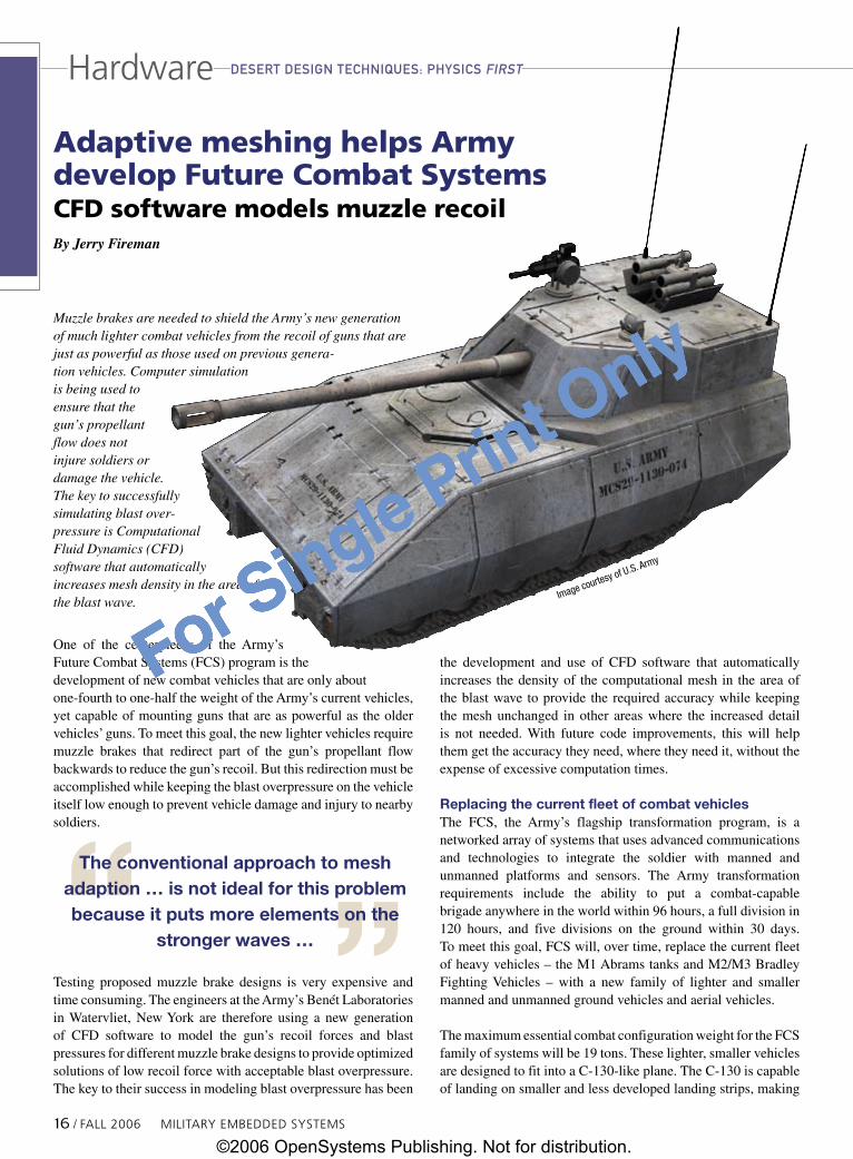
Muzzle brakes are needed to shield the Army’s new generation of much lighter combat vehicles from the recoil of guns that are just as powerful as those used on previous genera-tion vehicles. Computer simulation is being used to ensure that the gun’s propellant flow does not injure soldiers or damage the vehicle. The key to successfully simulating blast over-pressure is Computational Fluid Dynamics (CFD) software that automatically increases mesh density in the area of the blast wave.
One of the centerpieces of the Army’s Future Combat Systems (FCS) program is the development of new combat vehicles that are only about one-fourth to one-half the weight of the Army’s current vehicles, yet capable of mounting guns that are as powerful as the older vehicles’ guns. To meet this goal, the new lighter vehicles require muzzle brakes that redirect part of the gun’s propellant flow backwards to reduce the gun’s recoil. But this redirection must be accomplished while keeping the blast overpressure on the vehicle itself low enough to prevent vehicle damage and injury to nearby soldiers.
Testing proposed muzzle brake designs is very expensive and time consuming. The engineers at the Army’s Benét Laboratories in Watervliet, New York are therefore using a new generation of CFD software to model the gun’s recoil forces and blast pressures for different muzzle brake designs to provide optimized solutions of low recoil force with acceptable blast overpressure. The key to their success in modeling blast overpressure has been
the development and use of CFD software that automatically increases the density of the computational mesh in the area of the blast wave to provide the required accuracy while keeping the mesh unchanged in other areas where the increased detail is not needed. With future code improvements, this will help them get the accuracy they need, where they need it, without the expense of excessive computation times.
Replacing the current fleet of combat vehiclesThe FCS, the Army’s flagship transformation program, is a networked array of systems that uses advanced communications and technologies to integrate the soldier with manned and unmanned platforms and sensors. The Army transformation requirements include the ability to put a combat-capable brigade anywhere in the world within 96 hours, a full division in 120 hours, and five divisions on the ground within 30 days. To meet this goal, FCS will, over time, replace the current fleet of heavy vehicles – the M1 Abrams tanks and M2/M3 Bradley Fighting Vehicles – with a new family of lighter and smaller manned and unmanned ground vehicles and aerial vehicles.
The maximum essential combat configuration weight for the FCS family of systems will be 19 tons. These lighter, smaller vehicles are designed to fit into a C-130-like plane. The C-130 is capable of landing on smaller and less developed landing strips, making
ImagecourtesyofU.S.Army
The conventional approach to mesh adaption … is not ideal for this problem because it puts more elements on the
stronger waves …
16 / FALL 2006 MiLitAry EMBEDDED SyStEMS
dEsERt dEsigN tEchNiqUEs: physics FiRstHardware
©2006 OpenSystems Publishing. Not for distribution.
For Single Print Only

For Single Print Only
Hardwareit possible to deliver more vehicles closer to where they are needed. The first FCS unit will be fielded in 2008, with 32 brigades equipped by 2014.
Designing a muzzle brakeThe U.S. Army Armament Research, Development and Engineering Center’s (ARDEC’s) Weapon Systems & Technology (WST)/Benét Laboratories are colocated at the Watervliet Arsenal in upstate New York. Benét has been assigned the responsibility for designing the muzzle brake of the Mounted Combat System (MCS) tank cannon and the Non-Line of Sight Cannon (NLOS-C) artillery cannon, which are designed to replace the Abrams tanks and Paladin artillery vehicles as the Army’s primary fighting and artillery vehicles.
The 19-ton MCS isn’t heavy enough to absorb the full recoil force of its 120 mm gun, which fires as powerful ammunition as the 70- to 80-ton Abrams tank. So the MCS will use a muzzle brake to reduce the recoil, a device that is analogous to the thrust reversers that are used to slow down jet airliners after landing. The muzzle brake is a series of holes in the gun tube near the muzzle, through which the gas vents.
Figure 1 depicts a typical perforated muzzle brake operation. As a projectile passes the muzzle brake holes and flow begins to act on the gun tube, a force is generated opposing the recoil force. The venting process pulls the tube forward to counteract the recoil.
The design challenge is to reduce the recoil without putting excessive blast pressure on the vehicle. The challenge is complicated by the fact that a portion of the blast that hits the ground may be redirected back to the vehicle. A blast deflector may be used in an effort to funnel the blast waves coming out of the muzzle brake to the side rather than back towards the vehicle. It is important to be able to evaluate the performance of proposed muzzle brake and blast deflector designs with CFD, because it is expensive to build and test prototypes. Simulation also has the advantage of being able to determine peak pressures generated by exhaust gases at all points on the vehicle so that the vehicle can be designed to withstand them.
Challenges of simulating a blast waveDespite the advantages that it offers, simulation presents its own special challenges. The motion of the blast
wave must be modeled through a large volume of space. Mesh sizes of 0.5 mm or smaller are required at the edge of the blast wave in order to accurately capture the short-lived transients. When the mesh is coarser than this value, it artificially spreads out the blast wave and reduces the accuracy of peak pressure predictions. Having the mesh this fine throughout the entire solution domain, however, would increase the model size to the point where it would have theoretically taken centuries to solve, even on the fastest available computing hardware. Steady-state problems involving steep gradients, such as those occurring at shock fronts, are addressed by using a fine grid in one small region of the computational domain (that containing the most prominent gradients). In this case, however, the steep gradients associated with the blast wave rapidly sweep through the entire domain, so a novel approach is required to simulate the moving blast wave properly.
To overcome this problem, Benét Laboratories is taking advantage of the easy-to-use dynamic adaption capabilities of FLUENT CFD software from Fluent Incorporated, Lebanon, New Hampshire. CFD works by discretizing the flow domain into small cells, the sum of which is called a mesh, so that an algorithm can be applied to simultaneously solve the equations of motion for each cell. Dynamic adaption continually changes the density of the mesh throughout the domain so that as the
Muzzle BrakeProjectile
Recoil Force Muzzle Brake Force
Figure1S
econ
ds/it
erat
ion
Serial
Processors
I/O on
I/O off
Figure2
MiLitAry EMBEDDED SyStEMS FALL 2006 / 17
dEsERt dEsigN tEchNiqUEs: physics FiRst
©2006 OpenSystems Publishing. Not for distribution.
For Single Print Only

For Single Print Only
Hardware
blast wave propagates, the mesh in the area surrounding it is made finer. Regions that were refined earlier in the calculation are coarsened to a reduced mesh density, if the conditions there no longer require the increased detail. FLUENT allows the user to select the criteria upon which the mesh is refined or coarsened. Adaption based on the absolute pressure level has proven most effective for Benét to date, providing sufficient accuracy throughout the model without excessive computation time.
Validation caseIn order to validate the accuracy of the simulation, Benét engineers modeled a test rig at the Aberdeen Proving Ground consisting of the gun, mounted on a stand, that will go into the MCS. The simulation was performed on a Linux Networx 32-processor cluster with a Myrinet backbone and METIS load balancing. Engineers configured the zonal adaption capabilities of FLUENT to adapt the mesh every 15 time steps and to increase the number of elements in areas of high pressure by a maximum factor of 32. This simulation began at 1.7 million cells and increased to a peak of 34 million cells through adaption. Figure 2 shows how Linux Networx 32-processor cluster performance increases as more processors are utilized.
The test rig used to validate the simulation is shown in Figure 3. The validation case comparing FLUENT 6.1 results to experimental gun firing for the test is shown in Figure 4. Comparing the simulation predictions to physical testing has shown that CFD accurately predicts the primary or first blast wave peak pressures, but the pressure history below indicates that the CFD results for the peak pressures associated with the waves that are reflected from the ground are lower than the measured values. Furthermore, the
Time(milliseconds)
Pres
sure
(psi
)
1.0E+08
1.0E+07
1.0E+06
1.0E+05
1.0E+04
1.0E+03
1.0E+02
1.0E+01
1.0E+00
Elap
sed
Wal
l Tim
e (d
ays)
Ideal Grid SizeFor Shock Refinement
Current ValidationCase
0 5 10 15 20 25
Minimum Cell Size (mm)
1� / FALL 2006 MiLitAry EMBEDDED SyStEMS
dEsERt dEsigN tEchNiqUEs: physics FiRst
Figure4
Figure3
Figure5
©2006 OpenSystems Publishing. Not for distribution.
For Single Print Only
For Single Print Only
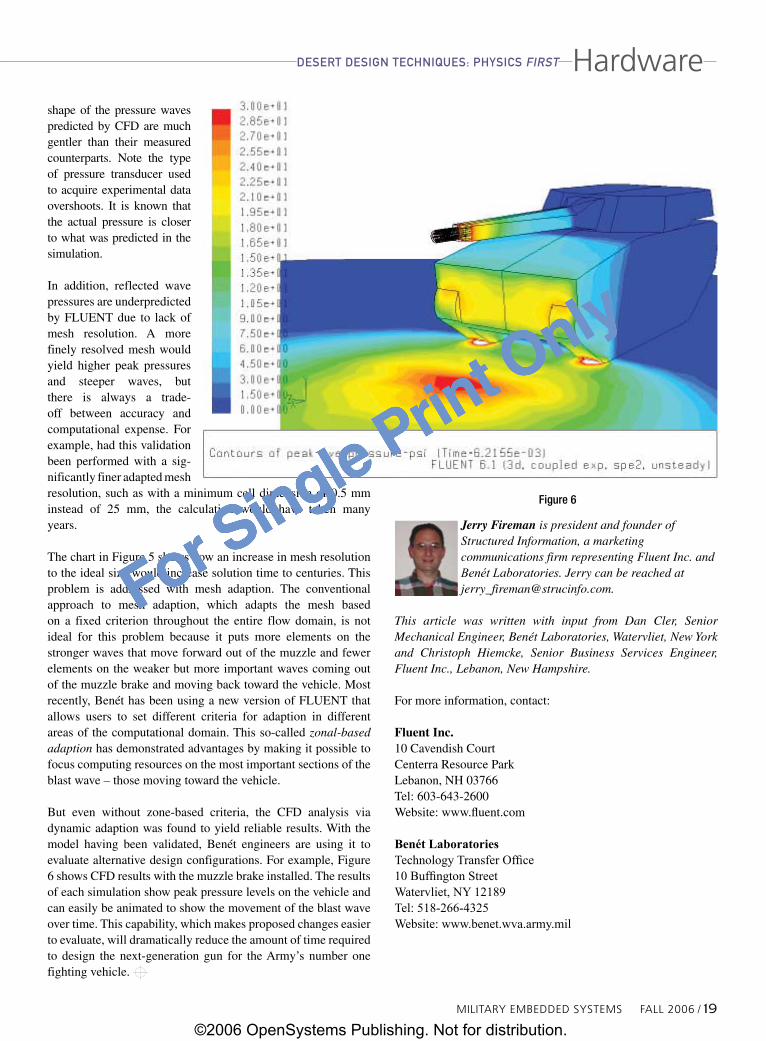
Hardwareshape of the pressure waves predicted by CFD are much gentler than their measured counterparts. Note the type of pressure transducer used to acquire experimental data overshoots. It is known that the actual pressure is closer to what was predicted in the simulation.
In addition, reflected wave pressures are underpredicted by FLUENT due to lack of mesh resolution. A more finely resolved mesh would yield higher peak pressures and steeper waves, but there is always a trade-off between accuracy and computational expense. For example, had this validation been performed with a sig-nificantly finer adapted mesh resolution, such as with a minimum cell dimension of 0.5 mm instead of 25 mm, the calculation would have taken many years.
The chart in Figure 5 shows how an increase in mesh resolution to the ideal size would increase solution time to centuries. This problem is addressed with mesh adaption. The conventional approach to mesh adaption, which adapts the mesh based on a fixed criterion throughout the entire flow domain, is not ideal for this problem because it puts more elements on the stronger waves that move forward out of the muzzle and fewer elements on the weaker but more important waves coming out of the muzzle brake and moving back toward the vehicle. Most recently, Benét has been using a new version of FLUENT that allows users to set different criteria for adaption in different areas of the computational domain. This so-called zonal-based adaption has demonstrated advantages by making it possible to focus computing resources on the most important sections of the blast wave – those moving toward the vehicle.
But even without zone-based criteria, the CFD analysis via dynamic adaption was found to yield reliable results. With the model having been validated, Benét engineers are using it to evaluate alternative design configurations. For example, Figure 6 shows CFD results with the muzzle brake installed. The results of each simulation show peak pressure levels on the vehicle and can easily be animated to show the movement of the blast wave over time. This capability, which makes proposed changes easier to evaluate, will dramatically reduce the amount of time required to design the next-generation gun for the Army’s number one fighting vehicle.
Jerry Fireman is president and founder of Structured Information, a marketing communications firm representing Fluent Inc. and Benét Laboratories. Jerry can be reached at [email protected].
This article was written with input from Dan Cler, Senior Mechanical Engineer, Benét Laboratories, Watervliet, New York and Christoph Hiemcke, Senior Business Services Engineer, Fluent Inc., Lebanon, New Hampshire.
For more information, contact:
Fluent Inc.10 Cavendish CourtCenterra Resource ParkLebanon, NH 03766Tel: 603-643-2600Website: www.fluent.com
Benét LaboratoriesTechnology Transfer Office10 Buffington StreetWatervliet, NY 12189Tel: 518-266-4325Website: www.benet.wva.army.mil
MiLitAry EMBEDDED SyStEMS FALL 2006 / 19
dEsERt dEsigN tEchNiqUEs: physics FiRst
Figure6
©2006 OpenSystems Publishing. Not for distribution.
For Single Print Only

For Single Print Only
Using resource partitioning to build secure, survivable military systemsBy Paul N. Leroux and Kerry Johnson
Network-centric warfare relies heavily on interconnected platforms, weapons, communications, and sensor systems. Of course, each of these “system of systems” contains its own intelligence, which also makes each vulnerable to software glitches, malicious attacks, or simply buggy code. One way to assure that a problem in one system doesn’t affect the entire Global Information Grid (GIG) is to use partitioned operating systems. In addition, partitioned environments also offer protection from priority inversions, resource starvation, and other inadvertent but not uncommon software behavior.
By providing access to accurate, timely information from virtually any location, the GIG promises to help war fighters identify and eliminate enemy threats with unprecedented efficiency. Nonetheless, the GIG mandate of networking all military systems will inevitably introduce its own threats, including viruses, Denial-of-Service (DoS) attacks, and other forms of cyber sabotage. To contain such attacks and ensure constant availability of mission-critical services, partitioning provides every software subsystem with a guaranteed share of computing resources.
Limited resourcesSafeguarding the reliability and security of net-centric warfare systems represents a significant challenge – a challenge made all the more difficult by the complexity of modern software. This complexity can undermine reliability for the simple reason that the more code a system contains, the greater the probability that coding errors or unanticipated software interactions will make their way into the field. It can also compromise security because hackers typically exploit such errors when they wish to damage or infiltrate a system. Unfortunately, no amount of testing can fully eliminate these problems, as no test suite could possibly anticipate every scenario that a complex software system may encounter.
The process of developing software for military systems presents a further complication. An integrator building a ground-vehicle system, for example, may need to integrate application programs from one vendor, protocol stacks from another,
an RTOS from yet another, and an embedded database from still another. The integrator must then combine those components with multiple software subsystems developed in-house, each written by a separate development group. Figure 1 shows some of the many software components that such a system may comprise.
Given the parallel development paths, performance problems invariably arise at the integration phase, when, for the first time, the various subsystems begin vying with one other for CPU time and other system resources. Subsystems that worked well in isolation now respond slowly, if at all. Unfortunately, many of these issues emerge only during integration and verification testing, when the cost of software redesign and recoding is at its highest.
To maintain secure operation and integrate multiple software subsystems successfully, the integrator must implement an architecture that prevents any component or subsystem from corrupting or monopolizing the computing resources (for example, memory and CPU time) that other subsystems require. Integrators could, in theory, achieve this goal by using hardware partitioning, an approach that uses a separate board or node to run each software subsystem or group of subsystems. Such an approach can both contain faults and reduce competition for shared resources. In military systems, however, the trend is toward integrating more
Figure120 / FALL 2006 MiLitAry EMBEDDED SyStEMS
OpERatiNg systEMsSoftware
©2006 OpenSystems Publishing. Not for distribution.
For Single Print Only

For Single Print Only
Software
functionality into a single slot. Such an approach not only cuts costs (“saving slots saves money”), but also minimizes weight and power consumption.
Secure compartmentsTo address these security and integration issues, some designs place virtual compartments, or partitions, around groups of software processes and allocate a predetermined set of resources, including CPU time, to each partition (Figure 2). The system can thus prevent processes in any partition from inadvertently or maliciously monopolizing resources needed by processes in other partitions. In the Defense and Aerospace (D&A) industry, many partitioned systems comply with the ARINC 653 specification, which provides a well-known though somewhat rigid and inefficient approach to resource partitioning.
Among other things, partitions can provide memory protection where the OS uses the Memory Management Unit (MMU) to control all memory access. A microkernel operating system, for instance, can partition applications, device drivers, protocol stacks, and file systems into separate, memory-protected processes. If any process, such as a device driver, attempts to access memory outside of its process container, the MMU will notify the OS, which can then terminate and restart the process.
This approach offers an immediate and measurable improvement to system reliability:
nPrevents coding errors in any process from corrupting other processes or the OS kernel
nAllows the developer to quickly identify, diagnose, and correct violations that could otherwise take weeks to isolate
nReduces fault-recovery times dramatically: Rather than having to reboot when a memory violation occurs, the system can simply restart the offending process
Avoiding task starvationNonetheless, building a reliable system involves more than partitioning functionality into separate memory domains. For many systems, ensuring resource availability is also critical. If a key subsystem is deprived of CPU cycles, for example, the services provided by that subsystem will become unavailable to users. In a DoS attack, for instance, an external system could bombard a device with requests that need to be handled by a high-priority process. That process will then overload the CPU and starve other processes of CPU cycles, making the system unavailable to users.
Also, in many cases, adding software functionality to a system can push it “over the brink” and starve existing applications of CPU time. Historically, the only solution was to either retrofit hardware or redesign software.
Fixed partition schedulersTo address these problems, some operating systems offer a fixed-cycle partition scheduler, typically based on ARINC 653, that allows the system designer to group processes into partitions and to allocate a percentage of CPU time to each partition. With this approach, no process in any given partition can consume more than the partition’s statically defined percentage of CPU time (for instance, 20 percent of the CPU).
Fixed-cycle schedulers have their drawbacks, however. Since the scheduling algorithm is fixed, partitions that aren’t busy consume their allocated CPU cycles in an idle state. Meanwhile, other partitions can’t access those unused cycles, even when they are busy and could benefit from the extra processing time. This approach squanders valuable (and available) CPU cycles and prevents the system from handling burst demands. Because of this “use it or lose it” approach, fixed partition schedulers can achieve only 70 percent CPU utilization.
Figure2
Partitioning on multicore processorsLike systems in every other industry,mission computers andsubsystemsforradar,flightcontrol,andsensorfusionaregrowingincomplexity,withavoraciousappetiteforcomputationalpower.Multicore processors offer the ideal performanceupgrade forsuch systems by delivering significantly greater performanceperwatt,ounce,andsquareinchthanconventionaluniprocessorchips. In fact, system designers will have little choice but toembracemulticoretechnology,sinceitformsthebasisofmostnewprocessordesigns.
Thus,anoperatingsystemmustbeable tosupport resourcepartitioningonmulticorehardware.Unfortunately,mostlegacyRTOSs,includingthosewithpartitioningschedulers,cancontrolonlyoneCPUorprocessorcoreatatime.Developersmust,asaresult,runaseparatecopyoftheRTOSoneachcoreofthemulticorechip.Becauseneithercopyownstheentiresystem,theapplicationdesigner,nottheOS,musthandlethecomplextaskofmanagingthechip’ssharedhardwareresources, includingphysicalmemory,peripheralusage,andinterrupthandling.Toavoid this complexity, systems designers should choose anRTOSthatcancontrolmultiplecoressimultaneously,managesharedresources,andprovidedynamicloadbalancingacrosscores–whilestillenforcingresourceguarantees.
MiLitAry EMBEDDED SyStEMS FALL 2006 / 21
OpERatiNg systEMs
©2006 OpenSystems Publishing. Not for distribution.
For Single Print Only

For Single Print Only
SoftwareThis cap on CPU utilization presents several undesirable choices to the system designer: Use a faster, hotter, more-expensive processor; limit the amount of software functionality that the system can handle; or simply tolerate slower performance. The cap also presents a “double whammy” to designs that must keep a significant percentage of CPU cycles in reserve for future applications or system enhancements.
Also, to request OS services or to communicate with other processes, applications must use the APEX interface as defined in the ARINC standard. This restriction prohibits legacy applications from leveraging the benefits of secure partitioning.
Adaptive partitioning schedulersAnother approach, called adaptive partitioning, addresses these drawbacks by providing a more dynamic scheduling algorithm. Similar to fixed-cycle partitioning, it allows the system designer
to reserve CPU cycles and memory for a process or group of processes. Designers can thus guarantee the load on one software subsystem won’t affect the availability of other subsystems.
Unlike fixed approaches, however, adaptive partitioning recognizes that CPU utilization is sporadic and that one or more partitions can often have idle time available. Consequently, an adaptive partitioning scheduler will dynamically reallocate those idle CPU cycles to partitions that can benefit from the extra processing time. This approach, which was pioneered by QNX Software Systems, offers the best of both worlds: It can enforce CPU guarantees when the system runs out of excess cycles (for guaranteed availability of applications and services) and can dispense free CPU cycles when they become available (for maximum CPU utilization and performance). In Figure 3, for example, Partition 2 consumes no more than 40 percent of CPU cycles when the system is running at capacity. But it can consume more than 40 percent whenever other partitions require less than their allocated CPU budget.
Adaptive partitioning offers several other advantages, including the ability to:
nUse real-time, priority-based scheduling when the system is lightly loaded, allowing systems to use the same scheduling behavior that they do today
nOverlay the partitioning scheduler onto existing systems without code changes, enabling users to launch existing POSIX-based applications in a partition
nAchieve 100 percent CPU utilization in a controlled fashion, allowing integrators to realize the benefits of time partitioning without the need for faster, more expensive processors
nGuarantee that fault-detection and recovery operations have the CPU cycles they need to repair software faults, thereby improving Mean Time To Repair (MTTR)
nAllow operators to remotely monitor or troubleshoot the system without interrupting the availability of critical applications
nStop malware and DoS attacks from stealing all available CPU time
OpERatiNg systEMs
Figure3
RSC# �� @www.mil-embedded.com/rsc
©2006 OpenSystems Publishing. Not for distribution.
For Single Print Only
For Single Print Only
SoftwareWhile adaptive partitioning offers greater flexibility, fixed-cycle scheduling may be desirable in some situations. To address this requirement, an implementation of adaptive partitioning should allow the system designer to configure a system with fixed partition budgets and no CPU time “borrowing.” This approach frees system designers to choose the most appropriate scheduling behavior for their application requirements.
Conflicting demandsEmbedded software is becoming so complex that, without some form of partitioning, system designers and software engineers will be hard-pressed to satisfy the conflicting demands for reliability, performance, security, time to market, and new features.
With resource partitioning, vendors can readily integrate subsystems from multiple software teams, subcontractors, and third party developers; allow new and upgraded components to run without compromising existing system behavior; and contain the effects of DoS attacks and other network-based exploits. If the partitioning solution also provides a flexible, efficient scheduler that allows 100 percent CPU utilization, then vendors can realize these benefits without having to incur the cost of faster, more expensive hardware.
Kerry Johnson is a senior product manager at QNX Software Systems, where he is responsible for product road maps and introducing new technology to the embedded
market. He has 20 years’ experience as a software design manager and project manager in companies such as Nortel, CrossKeys, and Research in Motion. He holds a Bachelor’s of Applied Science in Electronic Information Systems Engineering from the University of Regina, Saskatchewan.
Paul Leroux is a technology analyst at QNX Software Systems whose interests include high availability design, multiprocessing systems, and OS kernel architecture.
For more information, contact Paul or Kerry at:
QNX Software Systems 175 Terence Matthews Crescent Ottawa, Ontario Canada, K2M 1W8 Tel: 613-591-0931 E-mail: [email protected] Website: www.qnx.com
EXCALIBUR SYSTEMS
It’s about the support
EX
CALIBUR SYSTEMS
INC
.
ISO
9001:2000A147
71
RSC# �� @www.mil-embedded.com/rsc
OpERatiNg systEMs
©2006 OpenSystems Publishing. Not for distribution.
For Single Print Only
For Single Print Only
Using your existing test and measurement platform
to perform Serial RapidIO protocol analysis
By Barbara Aichinger
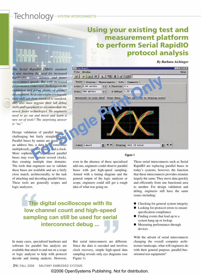
The Serial RapidIO (SRIO) standard is now meeting the need for increased bandwidth, lower latency, and faster interconnect speeds. But with increased performance comes new challenges in the validation and debug phases of product development. As design engineers migrate their skill sets from standard to standard, they also must migrate their lab debug skills and equipment to accommodate the newer, faster technologies. Do engineers need to go out and invest and learn a new set of tools? The surprising answer is “no.”
Design validation of parallel buses is challenging but fairly straightforward. Parallel buses by nature are made up of an address bus, a data bus (sometimes multiplexed), control signals, and a clock. More sophisticated high-speed parallel buses may even contain several clocks, thus creating multiple time domains. The tools that engineers use to validate these buses are available and are a fairly close match, architecturally, to the task of attaching and decoding parallel buses. These tools are generally scopes and logic analyzers.
In many cases, specialized hardware and software for parallel bus analysis are available that attach to and run on a scope or logic analyzer to help with protocol decode and timing analysis. However,
even in the absence of these specialized add-ons, engineers could observe parallel buses with just high-speed sampling. Armed with a timing diagram and the general output of the logic analyzer or scope, engineers could still get a rough idea of what was going on.
But serial interconnects are different. Since the data is encoded and involves clock recovery, simple high-speed data sampling reveals only eye diagrams (see Figure 1).
These serial interconnects such as Serial RapidIO are replacing parallel buses in today’s systems; however, the function that these interconnects provides remains largely the same: They move data quickly and efficiently from one functional area to another. For design validation and debug, engineers still have the same issues including:
nChecking for general system integrity nLooking for protocol errors to ensure
specification compliancenFinding events that lead up to a
system hang up or lockupnMeasuring performance through
devices
With the advent of serial interconnects changing the overall computer archi-tecture landscape, what will engineers do with their general purpose, parallel-bus-oriented test equipment?
Figure1
The digital oscilloscope with its low channel count and high-speed sampling can still be used for serial
interconnect debug ...
systEM iNtERcONNEcts
2� / FALL 2006 MiLitAry EMBEDDED SyStEMS
technology
©2006 OpenSystems Publishing. Not for distribution.
For Single Print Only
For Single Print Only
RSC# �� @www.mil-embedded.com/rsc
©2006 OpenSystems Publishing. Not for distribution.
For Single Print Only

For Single Print Only
The digital oscilloscope with its low channel count and high-speed sampling can still be used for serial interconnect debug in that it can show compliance to the specification eye diagrams. By its very nature, the oscilloscope can make the transition from parallel bus debug tool to serial interconnect debug tool, but what about the logic analyzer? The logic analyzer sampling time is not fast enough, and for protocol state analysis, there is
no separate signal that can be used as the clock. For serial interconnects pro-tocol analysis, engineers now have to choose between a new dedicated serial-interconnect-oriented tool or a new innovative add-on to their existing logic analyzer.
General purpose logic analyzer versus dedicated protocol analyzerWith the new Gbps serial interconnect standards, engineers must make some choices and accept some trade-offs when selecting validation and debug tools. One such choice is to select a dedicated protocol analyzer, or a general purpose logic analyzer coupled with a serial interconnect analysis probe.
A typical computer system employs multiple, different data bus and inter-connect technologies, and each typically will require some debug and verification efforts. If one chooses dedicated protocol-analysis tools, then analyzing each bus or interconnect will require a different tool, each requiring a unique user interface to learn. Furthermore, acquiring a dedicated protocol analyzer for every interconnect implementation can add up to hundreds of thousands of dollars. When a particular technology inevitably is replaced by a newer one, the dedicated analyzer will be useless.
On the other hand, most digital designers already have made the financial and learning-curve investments in a general purpose logic analyzer. Using these with a single-instrument-based family of analysis probes, designers work with the familiar user interface for every protocol analyzer used.
RSC# �� @www.mil-embedded.com/rsc
The general purpose logic analyzer, when customized with analysis probes, lets
users become familiar with one tool that is easily reconfigured for many different
protocols and standards.
systEM iNtERcONNEctstechnology
©2006 OpenSystems Publishing. Not for distribution.
For Single Print Only

For Single Print Only
Logic analyzer offers the greatest measurement flexibility and versatilityTo meet the challenges of design validation and test complexity that result from higher speeds and denser designs, Serial RapidIO designers need to look no further than their favorite logic analyzer vendor for a solution to these problems. Engineers have relied for decades on logic analyzers as an integral part of their validation and debug strategy. Analysis probes are essential to interface the logic analyzer with new, multigigabit (Gbps) architectures. Such probes sit between the target system and the logic analyzer, where they translate the high-speed serial interfaces into signals that can be processed by the logic analyzer (Figure 2).
On a single display, a single-instrument method offers the broadest spectrum of measurement capabilities, including cross-domain (simultaneous digital and analog) and cross-bus (simultaneous analysis of multiple protocols). Most analysis probes have software that facilitates inter-module collaboration, performs protocol decode, and simplifies triggering, store qualification, and performance monitoring of the device under test.
So the general purpose logic analyzer, when customized with analysis probes, lets users become familiar with one tool that is easily reconfigured for many different protocols and standards. Furthermore, the general purpose logic analyzer purchase can be more cost-
effective across more designs due to this customization ease. The new GUI that now accompanies most analysis probes and logic analyzers makes combining tools seamless and easy to use.
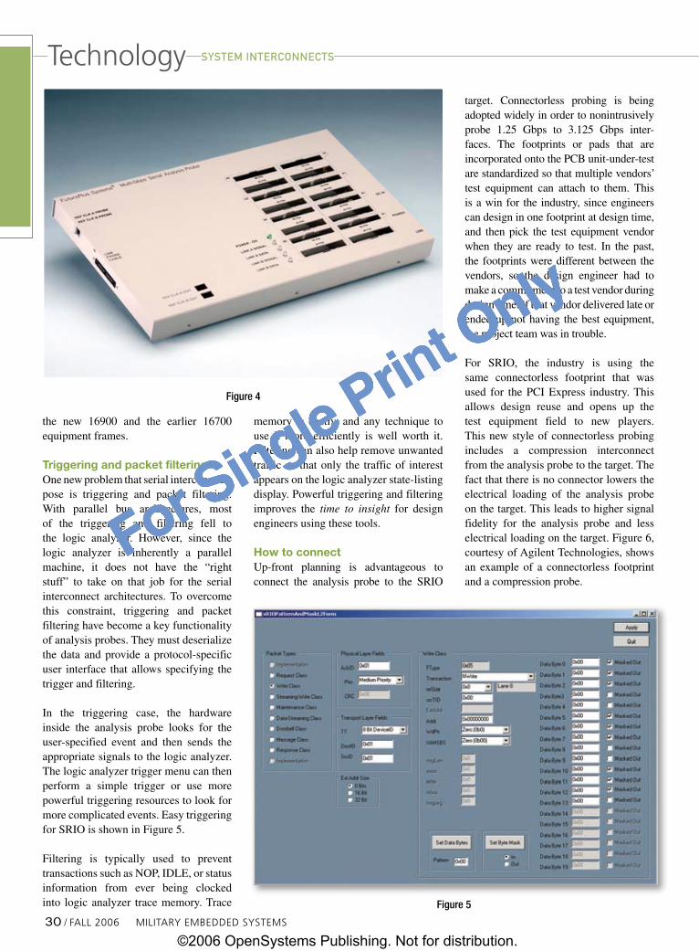
Specialized serial analysis probes include software that runs on the logic analyzer to give the user a complete decode of the packet protocol traffic. There is no need to look at cryptic hex or binary characters. Analysis of SRIO can be done from a high-level graphical view or from a detailed text view (see Figures 3A and 3B, FuturePlus Systems FS4410 software).
Do I need to buy a new logic analyzer?Existing logic analysis equipment can be used, at a substantial savings, to analyze modern interconnects including, for example, PCI-X, Serial RapidIO, PCI Express, and DDR.
For an up-to-date example, the FuturePlus FS4410 analysis probe can provide up to 3.125 Gbps Serial RapidIO analysis (Figure 4). Users who also are working with PCI Express applications can use the same probe and incorporate the SRIO performance with 2.5 Gbps PCI Express analysis for a substantially lower cost than would be incurred by acquiring a separate probe for each purpose. Each of these high-speed serial standards can be debugged using just two of the previous generation Agilent 16753 series of logic analysis cards, which will work in both
Figure2
Figures3Aand3B
MiLitAry EMBEDDED SyStEMS FALL 2006 / 27
technologysystEM iNtERcONNEcts
©2006 OpenSystems Publishing. Not for distribution.
For Single Print Only

For Single Print Only
RSC# �8 @www.mil-embedded.com/rsc©2006 OpenSystems Publishing. Not for distribution.
For Single Print Only
For Single Print Only
©2006 OpenSystems Publishing. Not for distribution.
For Single Print Only
For Single Print Only
the new 16900 and the earlier 16700 equipment frames.
Triggering and packet filteringOne new problem that serial interconnects pose is triggering and packet filtering. With parallel bus architectures, most of the triggering and filtering fell to the logic analyzer. However, since the logic analyzer is inherently a parallel machine, it does not have the “right stuff” to take on that job for the serial interconnect architectures. To overcome this constraint, triggering and packet filtering have become a key functionality of analysis probes. They must deserialize the data and provide a protocol-specific user interface that allows specifying the trigger and filtering.
In the triggering case, the hardware inside the analysis probe looks for the user-specified event and then sends the appropriate signals to the logic analyzer. The logic analyzer trigger menu can then perform a simple trigger or use more powerful triggering resources to look for more complicated events. Easy triggering for SRIO is shown in Figure 5.
Filtering is typically used to prevent transactions such as NOP, IDLE, or status information from ever being clocked into logic analyzer trace memory. Trace
memory is costly, and any technique to use it more efficiently is well worth it. Filtering can also help remove unwanted traffic so that only the traffic of interest appears on the logic analyzer state-listing display. Powerful triggering and filtering improves the time to insight for design engineers using these tools.
How to connectUp-front planning is advantageous to connect the analysis probe to the SRIO
target. Connectorless probing is being adopted widely in order to nonintrusively probe 1.25 Gbps to 3.125 Gbps inter-faces. The footprints or pads that are incorporated onto the PCB unit-under-test are standardized so that multiple vendors’ test equipment can attach to them. This is a win for the industry, since engineers can design in one footprint at design time, and then pick the test equipment vendor when they are ready to test. In the past, the footprints were different between the vendors, so the design engineer had to make a commitment to a test vendor during design time. If that vendor delivered late or ended up not having the best equipment, the project team was in trouble.
For SRIO, the industry is using the same connectorless footprint that was used for the PCI Express industry. This allows design reuse and opens up the test equipment field to new players. This new style of connectorless probing includes a compression interconnect from the analysis probe to the target. The fact that there is no connector lowers the electrical loading of the analysis probe on the target. This leads to higher signal fidelity for the analysis probe and less electrical loading on the target. Figure 6, courtesy of Agilent Technologies, shows an example of a connectorless footprint and a compression probe.
Figure4
Figure5
30 / FALL 2006 MiLitAry EMBEDDED SyStEMS
systEM iNtERcONNEctstechnology
©2006 OpenSystems Publishing. Not for distribution.
For Single Print Only

For Single Print Only
Since SRIO is a single lane or a four-lane, bidirectional link, all signals can fit on what is commonly known as the half-sized footprint. Complete details concerning the size of the footprint and pinout for SRIO can be found on the FuturePlus Systems website at: www.futureplus.com/download/appnotes/an_srio_fs4410.pdf.
Even though the SRIO footprint is small, there may not be enough room on some smaller and more densely packed designs for this footprint. Because of this constraint, some vendors now offer flying lead sets that are small and flexible.
Powerful, cost-effective solutions aboundIntegrating Gbps interconnects in today’s products need not compromise testing or break the capital equipment budget. High-performance and cost-effective tools are available to help design engineers tackle the most difficult test scenarios. Planning ahead for validation and debug is the key to successful product introduction. Engineers should team up with their fa-vorite test-and-measurement vendor for the latest product information and design-for-test techniques so they can sail smoothly through the debug and valida-tion phase of product development.
Barbara Aichinger is vice president and cofounder of FuturePlus Systems. She has more than 20 years of experience with various bus and interconnect architectures and has spoken on test and measurement topics worldwide. Prior to founding FuturePlus in 1991, she was a principal engineer at Digital Equipment Corporation (DEC). At DEC, Barbara was the project engineer in charge of DEC’s first RISC VMS-based machine. She was also DEC’s representative to the IEEE for bus architectures and standards. Barbara holds a BSEE from the University of Akron, Ohio and an MSEE from the University of Massachusetts.
For more information, contact Barbara at:
FuturePlus Systems 15 Constitution DriveBedford, NH 03110Tel: 603-472-5905E-mail: [email protected]: www.futureplus.com.
DIGITAL-LOGIC offers a wide range of embedded computer boards and systems for stationary and mobile applications
In-Vehicle PCssmallest dimensions, fanless, high reliability, rugged design
Further informations:
www.digitallogic.com
MPCX48 (IP50)
_ Intel® processor 800MHz
_ VGA, DVI, LVDS, Audio, Video-in
_ LAN, COM1, COM2, 6x USB
_ Options:WLAN, GPS, GSM, CAN
MPCX47 (IP65)
_ Intel® Pentium® M 738, 1.4GHz
_ VGA, DVI, LVDS, Audio, Video-in
_ LAN, COM1, COM2, 4x USB, 2x firewire, Digital I/O
_ Exchangeable mediapack 40GB automotive HDD 1x CF TypeII
_ Options: UPS-battery,preheating, GSM, GPS, WLAN, CAN
RSC# �1 @www.mil-embedded.com/rsc
Figure6
systEM iNtERcONNEcts technology
©2006 OpenSystems Publishing. Not for distribution.
For Single Print Only

For Single Print Only
Multi-function radar systems for the deployed warrior using VPX-REDI and RapidIOBy James Meyer
Next-generation radar will need to provide enormous flexibility in terms of modes and functions. This application requirement will drive performance demands that have architectural implications for radar computing and electronics.
Advanced Multi-Function Radar (MFR) systems must simultaneously provide multimode search, multitarget tracking, Synthetic Aperture Radar (SAR) imaging, and Space Time Adaptive Processing (STAP). These systems will be deployed in some of the harshest and most demanding environmental conditions inside Unmanned Aerial Vehicles (UAVs), manned aircraft, and ship- and ground-based radar systems. The combined requirement of performance and ruggedization makes it challenging to service MFR applications using yesterday’s Commercial Off-the-Shelf (COTS) technologies. However, COTS solutions based on open standards are now meeting the challenge of next-generation requirements. The combination of massive fabric bandwidth, Field Programmable Gate Array (FPGA) processing power, PowerPC high-compute density farms, and standards-based I/O housed in a conduction-cooled system address the simultaneous requirements of performance within an enclosure that can face the extremely hazardous field conditions found in deployed radar. VPX-REDI, a next-generation standard that combines the VITA 46 and VITA 48 standards (www.vita.com) with RapidIO (www.rapidio.org), significantly advances the robustness and performance of COTS sensor computing.
Challenges of mission-critical systemsFigure 1 shows an example flow of front-end data acquisition to back-end data processing and control. The challenge is to
engineer and integrate highly reliable mission-critical systems that provide the deployed warrior with radar and navigation capabilities required for very challenging missions.
A typical leading-edge problem involves minimizing the enemy’s broadband jamming efforts or eliminating ground or sea clutter located at arbitrary or unknown locations. The solution is to compute and track the angular locations of the jammers or clutter by appropriately processing the received signals and then adaptively generating a time-and-frequency-varying antenna pattern that places angular pattern nulls at the computed jammer location(s). Actual implementation depends upon a number of basic capabilities:
nMultielement antenna (8 to 100 elements)nSeparate receiver channel and A/D for each element/channelnEfficient mapping of dedicated hardware for the pulse
compression algorithms on FPGA modulesnTightly coupled fabric connectivity for corner-turning
operations nData exchanges with the high compute density processing
modules for the final STAP and data processing
The I/O distribution for the STAP application described above entails more than 10 GBps of bisection bandwidth within a system and gigaflops of processing power. The two most challenging areas
Figure1
Phot
oco
urte
syo
fU.S
.Nav
y
systEM iNtERcONNEcts
32 / FALL 2006 MiLitAry EMBEDDED SyStEMS
technology
©2006 OpenSystems Publishing. Not for distribution.
For Single Print Only
For Single Print Only
RSC# �� @www.mil-embedded.com/rsc
©2006 OpenSystems Publishing. Not for distribution.
For Single Print Only

For Single Print Only
of the problem, shown in Figures 2 and 3, are the real-time receive beamforming computational rate at up to 40 MHz and the adaptive beam-forming weight computations at a rate of 100 Hz to 1,000 Hz.
Open standard COTS systemsBy providing a modular COTS system based on open standards, the exceptionally demanding I/O in GBps and processing requirements of 10 to 100 GFLOPS for STAP and SAR algorithms can be met by combining the front-end functionality of high-speed microwave tuners and high-speed A/Ds in the speed range of 3 GHz or greater. Additionally, FPGAs and PowerPC resource modules are used for dedicated high-speed computations such as pulse compression operations for high-range resolution; effective short pulse response derived from the long, high-energy transmitted pulses; and lastly, returns. The complete processing chain operating on the three-dimensional (3D) radar data cube is shown in Figure 4.
A system host carrier module(s) is needed to orchestrate and synchronize the radar receiver/exciter and data collection control and to prosecute the I/O distribution among the various FPGAs for signal conditioning and the general purpose processors for data processing and image formation. The switching fabric connects all of the modular components in the system facilitating the quick and efficient exchange of data between processors. This enables the implementation of corner-turning for the SAR algorithm at the maximum data rates of the packet switched Serial RapidIO fabric. The gold standard measure of fabric bandwidth in an all-to-all data exchange such as this one is bisection bandwidth. Bisection bandwidth measures the interconnect capacity between any randomly drawn halves of a topology. A RapidIO fabric in
Figure2
Figure3
Figure4
systEM iNtERcONNEcts
3� / FALL 2006 MiLitAry EMBEDDED SyStEMS
technology
©2006 OpenSystems Publishing. Not for distribution.
For Single Print Only
For Single Print Only
Fast Is Not Good Enough.Fast Is Not Good Enough.
“It” is information. And as a leading supplier ofHigh-Performance Analog, Digital, and
Serial I/O, we offer Large FIFOs, Large FPGAs andthe Highest Bus Speed in the industry.
“It” is information. And as a leading supplier ofHigh-Performance Analog, Digital, and
Serial I/O, we offer Large FIFOs, Large FPGAs andthe Highest Bus Speed in the industry.
Call about our FreeLoaner Board offers.
VMEVME PMCPMC PCIPCI 104+104+ cPCIcPCI
Phone: 800-653-9970 Fax: 256-880-8788 www.generalstandards.com
Get the FreeMission Critical Report:
Top Ten Things toRemember
Before Specifyinga Data Acquisition Board
RSC# �� @www.mil-embedded.com/rsc
©2006 OpenSystems Publishing. Not for distribution.
For Single Print Only
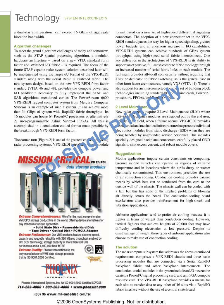
For Single Print Only
a dual-star configuration can exceed 16 GBps of aggregate bisection bandwidth.
Algorithm challengesTo meet the grand algorithm challenges of today and tomorrow, such as the STAP spatial processing algorithm, a modular, hardware architecture – based on a new VITA standard form factor and switched I/O fabric – is required. The focus of the future STAP-capable radar system solution described later will be implemented using the larger 6U format of the VPX-REDI standard along with the Serial RapidIO switched fabric. The new system design, based on the new VPX-REDI form factor standard (VITA 46 and 48), provides the compute power and I/O bandwidth necessary to fully implement the STAP and SAR algorithms mentioned earlier. The PowerStream 6600 VPX-REDI rugged computer system from Mercury Computer Systems is an example of such a system. It can achieve more than 34 GBps of system-wide RapidIO fabric throughput. Its 16 modules can house 64 PowerPC processors or alternatively 21 user-programmable Xilinx Virtex-4 FPGAs. All this is accomplished in a conduction-cooled format made possible by the breakthrough VPX-REDI form factor.
The corner-turn (Figure 2) is one of the greatest challenges facing radar processing systems. VPX-REDI introduces a new module
format based on a new set of high-speed differential signaling connectors. The adoption of a new connector set in the VPX-REDI standard paves the way for higher speed signaling, greater power budgets, and an enormous increase in I/O capabilities. VPX-REDI systems can achieve hundreds of GBps system throughput using high-speed serial fabric interconnects. One key difference in the architecture of VPX-REDI is its ability to support an expansive, full-mesh compute fabric topology through an increased number of serial fabric links on each module. The full mesh provides all-to-all connectivity without requiring that a slot be dedicated to fabric switching, as is the general case in other form factor architectures, namely VXS (VITA 41). There is also support for an interconnected common set of building block technologies including standard I/O mezzanine cards, PowerPC processors, FPGAs, and RapidIO fabric.
2 Level MaintenanceNew radar systems require 2 Level Maintenance (2LM) where individual electronics modules are swapped out by the end user, literally in the field, when a failure occurs. VPX-REDI provides the electrical and mechanical infrastructure that protects individual electronics modules from static discharge (ESD) when they are being handled by ungrounded service personnel. This includes specially designed backplane connectors, carefully placed GND signals to sink excess current, and robust module covers.
RuggedizationMobile applications impose certain constraints on computing. Ground mobile vehicles can operate in regions of extreme temperature and in locations where the air is dusty or worse: chemically contaminated. This environment precludes the use of air convection cooling. Conduction cooling provides passive means by which heat can be conducted from the card to the outside wall of the chassis. The chassis wall can be cooled with a fan, but this has none of the implied problems of blowing air directly across the board. The conduction-cooling board exoskeleton also provides reinforcement for high-shock and vibration applications.
Airborne applications tend to prefer air cooling because it is lighter in terms of weight than conduction cooling. However, tactical fighters that achieve heights of 70,000 feet may have difficulty cooling electronics at low pressure. Despite its disadvantage of weight, these types of airborne applications also choose to make use of conduction cooling.
The solutionThe radar compute subsystem that addresses the above-mentioned requirements comprises a VPX-REDI chassis and three basic processing modules that are connected via a Serial RapidIO backplane fabric and other backplane interconnects. The conduction-cooled modules in the system include an I/O mezzanine carrier, a PowerPC signal processing card, and an FPGA compute resource card. The VPX-REDI backplane provides a means for each slot to transfer data to any other of 16 slots via a RapidIO fabric interface without the use of a central switch card.
RSC# �� @www.mil-embedded.com/rsc
systEM iNtERcONNEctstechnology
©2006 OpenSystems Publishing. Not for distribution.
For Single Print Only
For Single Print Only
The I/O carrier module is a smart (processor-based) I/O mezzanine carrier that also serves as the scalar data and control processor for the radar receiver/exciter. It contains two MPC8548 processors that can serve as application processors or I/O engines servicing respective mezzanine card sites. The two mezzanine cards support PMC-X or XMC interfaces. This provides systems integrators with a wide and established ecosystem of option cards that may be incorporated.
The High-Compute-Density (HCD) module is a quad PowerPC AltiVec processor resource board. Each MPC7448 processor on the HDC operates at 1.4 GHz with a 400 MHz DDR2 memory interface. Each HCD module contains four PowerPC Compute Nodes (CNs) connected by a low-latency RapidIO crossbar to implement the network of fully connected floating point processors necessary to provide the GFLOPS of processing power for SAR and STAP algorithms.
The FPGA resource board houses three user-programmable Xilinx Virtex-4 FPGAs and can be delivered with an FPGA Developer’s Kit (FDK). This kit puts the basic building blocks needed for system integration at the fingertips of developers: RapidIO fabric and Serial FPDP bridge end-point IP, data movement functionality, memory controllers, and so on.
A holistic solution for next-generation radarMulti-function radar presents enormous challenges for system integrators, but COTS solutions based on open standards are now meeting them. The combination of massive fabric bandwidth, FPGA processing power, PowerPC high-compute density farms, and standards-based I/O is one important set of ingredients in challenging multi-function radar applications. The additional challenge is to house these features within a conduction-cooled enclosure that can face the extremely hazardous field conditions characteristic of field deployments.
James Meyer is a senior systems applications engineer at Mercury Computer Systems. He is responsible for applying Mercury’s high-performance multicomputer technology to customer projects including radar and sonar
signal processing systems. Prior to joining Mercury, James worked at CSPI and Radix Systems on the development of noise abatement systems for submarines. He earned a Masters in Computer Science from Johns Hopkins University and a dual Bachelor’s degree in Electrical Engineering and Bioengineering with honors from Syracuse University.
To learn more, contact James at:
Mercury Computer Systems, Inc.199 Riverneck RoadChelmsford, MA 01824Tel: 301-572-3012E-mail: [email protected]: www.mc.com
RSC# �� @www.mil-embedded.com/rsc
systEM iNtERcONNEcts technology
©2006 OpenSystems Publishing. Not for distribution.
For Single Print Only
For Single Print Only
Mil tech trends
Yet the DoD relies almost exclusively on COTS software in application form, as operating systems, development tools, or communications protocols. While the DoD has been successful at either creating or endorsing software standards such as DO-178B, ARINC-653, DoDAF, and DDS, COTS companies choose to follow these standards of their own free will because there’s money to be made. In addition, these standards are either used by other customers besides the DoD – thus increasing the vendor’s total available market and hence the possible upside return on investment – or the standards aren’t much more than “military wrappers” put around an already in-use COTS software standard such as TCP/IP. Take a look at the DoD’s mandate to use IPv6 (in lieu of IPV4) and it’s obvious that only when the entire Internet community moves to IPv6 will the DoD meet its goal and stop issuing waivers for IPv6 nonconformance.
What the military needs to realize is how and why COTS software is created. Armed with this knowledge, specifiers and prime- and subcontractors will have an easier time mapping their COTS software requirements and expectations against what the open market is likely to do. In the accompanying article, The emerging practice of software product line development by Dr. Charles Krueger of BigLever Software, the author outlines the decision process that COTS software developers go through before bringing their products to market. Most importantly, he points out that software is rarely written as a stand-alone product anymore; instead, vendors create software product lines that are based upon predefined variations decided during development.
Charles offers some valuable insight into the four-step process used either consciously (or unknowingly) by COTS software companies. Understanding how COTS software is developed offers a valuable lesson that will aid program managers in specifying software, planning for tech refresh and code updates, and eventually dealing with preplanned obsolescence and possible porting to alternative platforms or software environments.
The COTS software market doesn’t run on DoD timeBy Chris A. Ciufo
1 It has been widely rumored that Apple’s counter to the French mandate was that the company would stop offering iTunes downloads to French IP addresses. With more than 80 percent market share in the portable music market, Apple probably had little to fear.
The U.S. military is long past the days of being able to design all of its software from scratch or mandate certain requirements that force COTS software companies to write code a certain way. One only has to look at defunct languages such as Forth or the barely commercially viable Ada environment to understand that the military has little or no clout with the COTS software industry. If Apple didn’t bend to the pressure from the French government to open up its iTunes COTS software to non-iPod and non-Digital Rights Management (DRM) downloads1 and if Microsoft can continue to drag its collective Windows feet in the face of European Commission threats, then the U.S. military doesn’t have a prayer at influencing COTS software. The civilian collective markets of Europe are orders of magnitude larger than the DoD’s consumption of COTS software.
EVME Now
Check out OpenSystems Publishing’s new VME E-site, VME Now, focused exclusively on VMEbus. You’ll find up-to-the-minute, in-depth coverage on the latest VME technology news, along with:
• Standards and specifications• Discussion threads• Breaking news• RSS newsfeeds• Editor-moderated
technical panels • White papers• Blogs• And more!
site
Just go to:www.vmenow.com
3� / FALL 2006 MiLitAry EMBEDDED SyStEMS
cOts sOFtwaRE: FROM cONcEpt tO REaLity
©2006 OpenSystems Publishing. Not for distribution.
For Single Print Only
For Single Print Only
Mil tech trends
The emerging practice of software product line developmentBy Charles W. Krueger, PhD
A new class of software development methods, tools, and techniques is emerging that greatly
simplifies the engineering of product line portfolios. The improvements are so large that they
impact the fundamentals of how companies do business.
In today’s customer-driven environment, most companies target the needs of their prospective customers by creating a product line – a portfolio of closely related products with variations in features and functions – rather than just a single product. For example, a company that develops a radar countermeasures system will not be content selling that technology to just one client on one platform, but rather will see great economic benefit to engineering many variations of that product. Product variations could encompass different requirements for separate branches of the military, cockpit manufacturers, export rules and localizations for various countries, and a diversity of feature options and price points to support a wide range of anticipated and unanticipated customer requirements.
For companies that utilize embedded software in their products, this product diversity poses a serious problem. Tools and techniques for software development tend to focus on individual products. As a result, developing software for a product line is extremely complex due to multiple intertwined products, features, and production deadlines – all aimed at moving target markets. These tactical software development challenges are big enough to impede the realization of business-critical goals and strategies.
A new class of software development methods, tools, and techniques – collectively referred to as software product line development – is emerging to address this problem, offering improvements in development time to market, cost, quality, and portfolio scale and scope. What is most interesting is the
magnitude of tactical and strategic improvements that are possible, not measured in percentage points but more commonly in factors of 2 to 10. These improvements are so large that they impact the fundamentals of how companies compete.
The genesis of software product line development methodsManufacturers have long used analogous engineering techniques to create a product line of similar products using a common factory that assembles and configures parts designed to be reused across the varying products in the product line. For example, automotive manufacturers can now create thousands of unique variations of one car model using a single pool of carefully architected parts
and one factory specifically designed to configure and assemble those parts.
The idea of manufacturing software from reusable parts has been around for decades, but success has been elusive.
Recent advances in the software product line field have demonstrated that narrow and strategic application of these concepts can yield orders-of-magnitude improvements in software engineering capability. The result is often a discontinuous jump in competitive business advantage, similar to that seen when manufacturers adopt mass production and mass customization paradigms.
The characteristic that distinguishes software product lines from previous efforts is predictive versus opportunistic software reuse. Rather than put general software components into a library in
The idea of manufacturing software from reusable parts has been around for decades, but success has been elusive.
MiLitAry EMBEDDED SyStEMS FALL 2006 / 39
cOts sOFtwaRE: FROM cONcEpt tO REaLity
©2006 OpenSystems Publishing. Not for distribution.
For Single Print Only
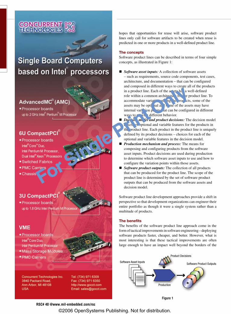
For Single Print Only
Mil tech trendshopes that opportunities for reuse will arise, software product lines only call for software artifacts to be created when reuse is predicted in one or more products in a well-defined product line.
The conceptsSoftware product lines can be described in terms of four simple concepts, as illustrated in Figure 1:
nSoftware asset inputs: A collection of software assets – such as requirements, source code components, test cases, architecture, and documentation – that can be configured and composed in different ways to create all of the products in a product line. Each of the assets has a well-defined role within a common architecture for the product line. To accommodate variation among the products, some of the assets may be optional and some of the assets may have internal variation points that can be configured in different ways to provide different behavior.
nDecision model and product decisions: The decision model describes optional and variable features for the products in the product line. Each product in the product line is uniquely defined by its product decisions – choices for each of the optional and variable features in the decision model.
nProduction mechanism and process: The means for composing and configuring products from the software asset inputs. Product decisions are used during production to determine which software asset inputs to use and how to configure the variation points within those assets.
nSoftware product outputs: The collection of all products that can be produced for the product line. The scope of the product line is determined by the set of software product outputs that can be produced from the software assets and decision model.
Software product line development approaches provide a shift in perspective so that development organizations can engineer their entire portfolio as though it were a single system rather than a multitude of products.
The benefitsThe benefits of the software product line approach come in the form of tactical improvements in software engineering – deploying software products faster, cheaper, and better. However, what is most interesting is that these tactical improvements are often large enough to have an impact well beyond the borders of the
Software Asset InputsSoftware Product Outputs
Product Decisions
Production
Figure1
RSC# 40 @www.mil-embedded.com/rsc
©2006 OpenSystems Publishing. Not for distribution.
For Single Print Only

For Single Print Only
Mil tech trendscOts sOFtwaRE: FROM cONcEpt tO REaLity
engineering department, offering strategic competitive benefits.
Time to marketIf new products in a software product line are engineered and brought to market faster, strategic business benefits result. Companies with software product line success stories have reported decreasing their time to market for new products by factors of 2 to 50 when compared to the conventional techniques they were using.
QualityQuality benefits of software product lines can be measured in two ways. The first is how well each product matches the needs of each customer. The mass customization capabilities of software product lines directly address this measure of quality. The second is the rate of defects found in each of the products in the product line, which can also be significantly improved due to software reuse. Companies have reported reductions in defect rates as high as 96 percent.
Engineering costSoftware product line techniques can significantly increase the productivity of software engineers, seen as a reduction in the effort and cost required to develop, deploy, and maintain a portfolio. Typical productivity improvements reported in case studies range between a factor of 2 to 3, though higher factors are not uncommon.
Figure 2 illustrates the effort – and thus cost – required to develop, deploy, and maintain a portfolio. The red line represents a conventional productivity line. The blue line represents a productivity line of the pioneering efforts in software product lines, where a significant up-front effort was typically required (seen as the high Y-axis intercept) to launch a software product line. The green line represents the new generation of software product line methods that can achieve higher productivity gains with much less up-front effort.
ScalabilityA company that takes a software product line approach needs to scale, without constraints, to whatever number of products is optimal for the business. The benefit of software product line approaches is that they can often scale to orders-of-magnitude more products in a portfolio than conventional software engineering techniques.
Advantages of software product line developmentThe emerging practice of software product line development offers significant tactical software engineering improvements as well as strategic business advantages. In much the same way that manufacturers advanced from manual labor to mass production to mass customization, software product line development allows software development organizations to advance from labor-
intensive to highly efficient and automated portfolio development methods. To learn more about these methods and successes stories, see the community website www.SoftwareProductLines.com.
Charles W. Krueger, PhD, is founder and CEO of BigLever Software and has 20 years of experience in software product line development. He has helped companies establish software product line practices, including Software Product Line Hall of Fame inductees Salion and LSI Logic. He is the
author of more than 25 articles, including ACM Software Reuse. He is a frequent organizer and speaker for the International Software Product Line Conferences and moderates the community website SoftwareProductLines.com. He received his PhD in Computer Science from Carnegie Mellon University.
To learn more, contact Charles at:
BigLever Software, Inc.10500 Laurel Hill CoveAustin, TX 78730Tel: 512-426-2227E-mail: [email protected] Website: www.biglever.com
Figure2
MiLitAry EMBEDDED SyStEMS FALL 2006 / �1
©2006 OpenSystems Publishing. Not for distribution.
For Single Print Only

For Single Print Only
All-in-oneSBCwithcellularandZigBeeIn the industrial COTS world, therequirementsforextendedtemperatureandmyriadconnectivityapplyequallywell tomilitaryanddefenseapplica-tions.TheLBC-GX500,anAMDGeodeGX500Pentium-classprocessor-basedEBXboard,specificallytargetssystemsthatneedcellular,ZigBee,andmultiplewiredconnections.Designedtooper-ateat -40°C to+85°C, theboardoffers four wireless connections:Wi-Fi, GSM/GPRS cellular, CDMAcellular, and ZigBee RF. Not to relysolelyonwireless,italsoincludesa10/100Ethernetport,sixUSBports,sixCOMchannels,adial-upmodem,and48paralleldigitalI/Olines.
The LBC-GX500 has everything you’d expect from a full-featured EBX-compliantSBC(5.75"x8.0"or146mmx203mm),includingCRTandLCDinterfaces,keyboard/mouse,LPTparallelport,AC97audio,andanoptional12-bitA/D.Diskdrives(floppy,HDD,CompactFlash,andDiskOnChip)canbeeasilyconnected,andtheboardrunsWindowsCE,XPEmbedded,Linux,VxWorks,QNX,andprobablyafewothers.Amazingly,thisall-in-oneSBCconsumesonlyabout8Wduringnormaloperationanddoesn’trequireafan.
WinSystemswww.winsystems.comRSC#32072
Rugged handheld ready for deploymentTherearecertainly ruggedTabletPCsandlaptops,andthere are equally ruggedPDAs.ButliketheGoldilockschildren’s fable, sometimeswhat’s needed is a ruggedhandheld that’s right in themiddle. Enter the CATCHERby Catcher Holdings. TheCommunicationsAndTelemetryComputing Handheld forEmergencyResponse(CATCHER)isspecificallydesignedformilitary,govern-ment,andcivilianfirstrespondersinemergency(orbattlefield)deployments.Weighingjust2pounds(or3poundswithtwobatteries),theMIL-STD-810Fdevicecanwithstand3-footdrops,upto50gs,andisweatherresistant.
BasedonanIntelPentiumMwith2GBofDRAManda40GBHDD,theunitrunsaWindowsXPOSfeaturingpencomputingextensionsandoffersWi-Fi,Bluetooth,GPS,andoptionalCDMA,GSM/GPRS,andUWBcellularconnectiv-ity.Multimediaissupportedwithhardwarecodecs,andtheCATCHERcomescompletewithstereospeakersandamicrophone.The850nitbacklit6.4"VGAdisplayisintendedtobeusedinfullsun.OnboardsensorsincludeafingerprintreaderandUPCbarcodereader,andtheCATCHERcanbeoutfittedwithanoptionalRFIDinterrogator/readertoaidininventory(orhuman)tracking.
CatcherInc.www.catcherinc.comRSC#32086
Two many: Each is independentYou’ll find lots of dual-CPUSBCs in themarket, thoughrequiring conduction cool-ing admittedly narrowsthe searchquite abit. Still,whenultimateperformanceis a requirement, it’s bet-ter to have dual processorsubsystems – just like theC102fromAitechdoes.ThisMPC7448-based SBC usestwo 1.42 GHz CPUs, eachwithitsown1GBofECCSDRAM@166MHz,12MBofbootflash,256MBofuserflash,and128kBofNVRAM.ThenodesareinterconnectedviaPCI-Xat133MHz,andI/OfromthePCI-PCIbridgecanalsobefedtotheVMEback-planeatupto2eSST(320MBps)speeds.
Inaddition,therearefourEthernetports(two10/100/100andtwo10/100),twoUSB2.0ports,aSerialATAport,sixUSARTports,twoUARTports,and16TTL/eightdifferentiallines.TheboardcanaccommodatetwoPMCmodulesbutalreadyincludestwodualredundantMIL-STD-1553portsonthebasecard.Ofcourse,sincethisboardisdesignedforharshmilitaryenvironments,therearetherequisitefeaturessuchasBITandIBIT,alongwithvariousonboardmoni-tor/debuggerutilities.
Aitechwww.rugged.comRSC#31018
Adaforreal-timeWindowsRTX is a low-footprint (250 kB ofRAM), high-performance extensionto Windows that allows apps torun in real timewith features likepreemptivescheduling.Ifyouhap-pen to be runningArdence’s RTX,you’reprobablydoingitwithC/C++.ButsupposeyoucouldrunAda.WouldthismakeRTXmoreappealingforanembeddedmilitaryenvironment?DDC-Ithinksso.They’veintroducedtheSCOREIDEforRTXversion6.x,whichpromisesamixedAda/C/EmbeddedC++environment–allinadeterministicWindowsframeworkwhereAdatasksrunasRTXthreads.
SCOREisamultilanguage,object-orientedIDEfordevelopinganddeploy-ingsafety-criticalapplications.ItincludesoptimizingcompilersforAda,C,EmbeddedC++,andFortran77.TheGUI-basedtoolincludessourceeditor,projectmanager,andautomatedbuild/makeutilities.Italsohasamultifunc-tiondebuggertomakelifeeasierwithrespecttosyntax,expressions,stacks,andothercode“gotchas.”SCOREcandebugRTXapplicationsrunninginboththeWin32andRTSSenvironments,anditcanberuntimecertifiabletoDO-178B.
DDC-Iwww.ddci.comRSC#32087
Editor’s Choice Products are drawn from OSP’s product database and press releases. Vendors may add their new products to our website at www.opensystems-publishing.com/vendors/submissions/np/ and submit press releases at www.opensystems-publishing.com/news/submit. OSP reserves the right to publish products based on editors’ discretion alone, and does not guarantee publication of any product entries.
�2 / FALL 2006 MiLitAry EMBEDDED SyStEMS
Editor’s Choice Products
©2006 OpenSystems Publishing. Not for distribution.
For Single Print Only

For Single Print Only
RSC# 4� @www.mil-embedded.com/rsc
©2006 OpenSystems Publishing. Not for distribution.
For Single Print Only
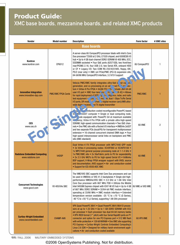
For Single Print Only
Vendor Modelnumber Description Formfactor #XMCsites
Baseboards
Kontronwww.kontron.com CP6012
Aserver-class6UCompactPCIprocessorbladewithIntel’sCoreDuoprocessorT2500at2GHz,E7520chipset,and6300ESBI/Ohub•Upto4GBdual-channelDDR2-SDRAM@400MHz,ECC,SODIMMsocketed•FourGbEports(82571EB),twofront/tworear/PICMG2.16,fourUSB2.0,twoSerialATA,onboardHDDor CF • Legacy I/O:Two COM RS-232/422/485, floppy, IDE,PS/2(rearonly)•XMC(x4PCIe)/PMC(PCI-X)expansionsite,64-bit/66MHzCompactPCIinterface,3.3V/5Vsupport
6UCompactPCI 1
InnovativeIntegrationwww.innovative-dsp.com
PMC/XMCFPGACards
VelociaPMC/XMCfamily integratesultra-fastsignalcapture,generation,andco-processingonanadvancedPMCarchitec-ture•Virtex-IIProFPGA•64/66PCIwithaprivateJN464-bituserI/Oport•XMCfour-laneRocketI/O(perVITA42)•AllowsforrapiddeploymentofSDR,signalintelligence,radar,andradiotestequipment•IncludesSIOmodule,dual1GbpsTx/RxSerialI/Oports,DRmodule16-channeldigitalreceivercard,UWBultra-widedigitalreceiver,andTXdigitaltransmitter
PMC/XMC 1
CESwww.ces.ch
RIO48076
Aruggedizedconduction-cooledreconfigurablePowerPC-based6UVME 2eSST computer • Single or dual computing node,eachnodeequippedwith:PowerPCG4atmaximumavailablefrequency;Virtex-IIProFPGAwithaprivateultra-high-speedSSRAM;high-speedcommunicationchannels•TwoGbEchan-nels•OnePMCsitewithaRocketI/Ointerface•VME64x2eSSTandtwoseparatePCIs(local/P0)fortransparentmultiprocessorextension•16-channelconcurrentchainedDMAlogic•Fourhigh-speedinterprocessorseriallinksonbackplaneandPMCsite(XMCstandard)
6UVME 2
RadstoneEmbeddedComputingwww.radstone.com
V4DSP
Dual Virtex-4 FX FPGA processor with MPC7448 GPP node•2xVirtex-4processingnodes:XC4VFX60orXC4VFX100•1xMPC7448generalpurposeprocessingnodeat1-1.4GHz•1xPMC/XMCsite•2xStarFabricportstoP0forexpandability•2x2.5GHzMGTstoP0forhigh-speedSerialI/O•VxWorksBSPsupport,V-WrapFPGAwrappersupportwithVHDLsourceanddocumentation,AXISsupport•Air-andconduction-cooled•SupportforICS-8550ADCXMC
6UVME 1
ConcurrentTechnologieswww.gocct.com
VX405/04xSBC
TheVME/VXSSBCsupportsIntelCoreDuoprocessorsandcanbeusedinVME64xorVXS41.3backplanes•Singleslothigh-performanceVME64x/VXS SBC • 2.0 GHz or 1.66 GHz IntelCoreDuoprocessorwith667MHzFSB•Utilizes theMobileIntel945GMExpresschipsetwithICH7-MI/Ohub•Upto4GBof667MHzDDR2SDRAM•32/64-bitPMCmoduleinterface,operatingat33/66MHz•XMCmodule interface•Extendedtemperature version available: -25 °C to+70 °C (E-Series),-40°Cto+55°C(J-Series),supporting1.66GHzprocessor
6UVMEorVXSVME 1
Curtiss-WrightEmbeddedwww.cwcembedded.com
CHAMP-AV6
VPXQuadPowerPC8641•QuadPowerPC8641/8641Dproces-sorsatupto1.33GHz•Upto1GBDDR2SDRAMwithECCperprocessor•Eachprocessorhasdual64-bitmemorybanks•VPX-REDIformat(1"pitch)withfourSerialRapidIOportsonP1connectorandoptionforonePCIExpressport•512MBflashwithwrite-protection•128kBNVRAM•OneXMCsitesupportingPCIExpress•Curtiss-WrightControlsEmbeddedComputing’sLinux2.6SDK•Designedformilitaryharsh-environmentappli-cations•Air-andconduction-cooledavailable
6UVPXVME 1
�� / FALL 2006 MiLitAry EMBEDDED SyStEMS
Product Guide:XMc base boards, mezzanine boards, and related XMc products
©2006 OpenSystems Publishing. Not for distribution.
For Single Print Only

For Single Print Only
Vendor Modelnumber Description Formfactor #XMCsites
Curtiss-WrightEmbeddedwww.cwcembedded.com
VPX6-185DualPowerPC8641
AgeneralpurposeSBCwithFreescale8641PowerPCprocessor•Singleordualprocessore600coresatupto1.33GHz•Upto2GBDDR2SDRAMcontrolledbydual64-bitcontrollers•TwoPMC/XMCsitessupportingparallelPCIandPCIExpress•VPX/VPX-REDIformatswithfourAdvancedSwitchingIntercon-nect(ASI)switchportsonP1connectorandoptionforoneSerialRapidIOport•ContinuumSoftwareArchitecture(CSA)firmwareprovidingacomprehensivesuiteofsystemdebug,exerciser,andupdatefunctions,BIT,andnonvolatilememorysanitizationfunc-tion•Air-andconduction-cooledversions
6UVPXVME 2
MicroMemorywww.micromemory.com
MM-1600
AquadFPGAVPXVITA46carrierwithtwoPMC/XMCsitesandfourSerialRapidIOportsonP1•Targetsstreamingsignalsen-sorapplicationssuchassyntheticapertureandphasedarrayradar,signalintelligence,andSoftware-DefinedRadio•PrimaryDDRcapacity:2GB•CoSineprimarydevice:2VP70•CoSinecompaniondevice:SX55•Format:VITA41
6UVPXVME 2
MicroMemorywww.micromemory.com
MM-1650
AquadFPGAVPXVITA46carrierwithtwoPMC/XMCsitesandfourSerialRapidIOportsonP1•Targetsstreamingsignalsen-sorapplicationssuchassyntheticapertureandphasedarrayradar,signalintelligence,andSoftware-DefinedRadio•PrimaryDDRcapacity:2GB•CoSineprimarydevice:2VP70•CoSinecompaniondevice:LX160•Format:VITA46
6UVPXVME 2
MicroMemorywww.micromemory.com
MM-1550
AquadFPGAVXSVITA41carrierwithtwoPMC/XMCsitesandtwoSerialRapidIOportsonP0•Targetsstreamingsignalsen-sorapplicationssuchassyntheticapertureandphasedarrayradar,signalintelligence,andSoftware-DefinedRadio•PrimaryDDRcapacity:2GB•CoSineprimarydevice:2VP70•CoSinecompaniondevice:LX160•Format:VITA46
6UVXSVME 2
VMETROwww.vmetro.com
PhoenixM6000
AVXSI/OcontrollerwithdualXMC/PMCsitesanddual4GbpsFibreChannel•DualXMCsiteswithx8PCIExpressconnections•VXSinterfaceimplementedusingVirtex-4FXFPGA•AMCCPowerPC440SPprocessor•Dual4GbpsFibreChannelports•320MBps2eSSTVMEinterface•256(512)MBhigh-speedstreamingmemory•OnboardPCIExpressswitchforoptimaldataflow•Independent64-bit,133MHzPCI-XbusforeachPMCsite•Ruggedizedversionsavailable
6UVXSVME 2
VMETROwww.vmetro.com
PhoenixVXSSystems
Systemsbuiltaroundhigh-performanceprocessing, I/O,andmultichannel Gbps serial communications with supportingsoftware and firmware • High-performance data process-ingutilizingdualPowerPCanddualFPGACPUs•High-speedcommunications through a VXS fabric, multichannel datalinks, and raw or switch-packet protocols • High-speedserial communication, zero-latency switch cards • Intel-ligentPMC/XMC I/O controller, carrier, and recorderblade•TransComm FPGA CommunicationsToolbox for low-latency,efficientdatacommunications
6UVXSVME 1
MicroMemorywww.micromemory.com
MM-1500
AVMEboardthatincludestheV-4TMSXTMseriesofFPGAsfromXilinx•Targetsstreamingsignalsensorapplicationssuchassyntheticapertureandphasedarrayradar,signalintelligence,Software-DefinedRadio,andsemiconductorandmedicalimag-ing•PrimaryDDRcapacity:2GB•CoSineprimarydevice:2VP70•CoSinecompaniondevice:SX55•VITA41format
VME 2
MiLitAry EMBEDDED SyStEMS FALL 2006 / �5
Product GuideXMc base boards, mezzanine boards, and related XMc products
©2006 OpenSystems Publishing. Not for distribution.
For Single Print Only

For Single Print Only
Vendor Modelnumber Description Formfactor
XMCmezzanineboards
Curtiss-WrightEmbeddedwww.cwcembedded.com
RazorBladeIII-SX&IV-LX
OpticalfiberXMCmodules•Deliver24portsofwire-speedGbEperformanceovercopperandoptical fiberwhenusedwiththeSVME/DMV-680SwitchBladeGbEswitch•ProvideapowerfulbuildingblockthatcanbeusedtodesignIntra-Plat-formNetworks(IPN)thatlinkIP-basednetworksonboardair,land,andseavehiclesindefenseandaerospaceapplications•Suitableforapplicationswherehighsignalquality,securedatatransmission,andsurvivabilityareessential
XMC
Radstonewww.ics-ltd.com
ICS-8550
An XMC module designed to bring more bandwidth and processing power toSoftware-DefinedRadioapplications•FeaturestwoanaloginputsequippedwithAD9430210MHz,12-bitADCs,andaXilinxVirtex-4XC4VFX60FPGA•Optimizedforwidebandwidthfront-enddigitalsignalprocessingfordigitalreceiverapplicationsinsignalintelligenceandradarsystems•Fivelevelsofruggedizationavailable
XMC
VMETROwww.vmetro.com
SFMQuadSerialFPDPModule
Ahigh-performancePMC/XMCmodule•SupportsuptofoursimultaneousSerialFPDP(VITA17.1-2003)channels•Providesahigherleveloffunctionaldensitywithoutcreatingabottleneckgettingthedatatoandfromthebaseboard•SeparateDMAcontrollersforeachchannel•SupportsPCI-Xdatatransfersatspeedsupto133MHz•SupportsPCIExpressviatheXMCconnectorsandprovidesthefull2.5Gbpsdatarateperchannel•One,two,orfourSerialFPDPchannels•1.0625,2.125,and2.5GbpsPCIExpresslinkspeedperchannelinXMCformfactor•64MbFIFOperchannelwithprogrammableelasticity•VxWorksandLinuxsupport
XMC
Pentekwww.pentek.com
Model7142
Transceivermodule•Four-channelA/D,one-channelD/AwithVirtex-4FPGAs•Four125MHz14-bitA/Ds•Conduction-cooledandruggedizedversions•Com-pletesoftwareradiointerfacesolution•VITA42.0XMCcompatiblewithswitchedfabricinterfaces•Onedigitalupconverter•One500MHz16-bitD/A•768MBofDDR2SDRAM•32pairsofLVDSconnectionstotheVirtex-4FPGAforcustomI/OonP4
XMC,3U/6UCompactPCI,PCI
Pentekwww.pentek.com
7140Transceiver
Adualdigitalup/downconverterPMC/XMCwithFPGA•VITA42.0XMCcompatiblewithswitchedfabricinterfaces•Two105MHz14-bitA/Dsandfourdigitaldown-converters•Onedigitalupconverterandtwo500MHz16-bitD/As•32pairsofLVDSconnectionstotheVirtex-IIProFPGAforcustomI/OonP4•512MBofDDRSDRAM•Upto2.56secondsofdelayerdatacaptureat100MHz•Ruggedizedandconduction-cooledversionsavailable•Availablein3Uand6UCompactPCIandPCIformats•PCIformatSCAcompliant
XMC/PMC,3U/6UCompactPCI/PCI
Pentekwww.pentek.com
Model7140
A dual digital up/downconverter PMC/XMC with FPGA • Complete softwareradio transceiversolution•Ruggedizedandconduction-cooledversionsavail-able•VITA42.0XMCcompatiblewithswitchedfabricinterfaces•Two105MHz14-bitA/Ds•Fourdigitaldownconverters•Onedigitalupconverter•Two500MHz16-bit D/As • 512 MB of DDR SDRAM • Xilinx Virtex-II Pro FPGA • Up to2.56secondsofdelayordatacaptureat100MHz•32pairsofLVDSconnectionstotheVirtex-IIProFPGAforcustomI/OonP4
XMC/PMC,CompactPCI,PCI
ACT/Technicowww.acttechnico.com
8753
APrPMC/XMCmezzanine cardbasedon Freescale’sMPC7447AorMPC7448processor•CanbeusedinconjunctionwithVMEorCompactPCIcarriersorwithproprietarydesigns•64-128MBsolderedMirrorFlash;2MBhigh-speedSRAM;32kBSPIEEPROM;and2kBI2CEPROM•DualPMC/XMCVME64xcarrierwithVME2eSSTcapabilities
XMC/PrPMC
�6 / FALL 2006 MiLitAry EMBEDDED SyStEMS
XMc base boards, mezzanine boards, and related XMc productsProduct Guide
©2006 OpenSystems Publishing. Not for distribution.
For Single Print Only

For Single Print Only
Vendor Modelnumber Description Formfactor
Pentekwww.pentek.com
Model7142
Transceivermodule•Four-channelA/D,one-channelD/AwithVirtex-4FPGAs•Four125MHz14-bitA/Ds•Conduction-cooledandruggedizedversions•Completesoftwareradiointerfacesolution•VITA42.0XMCcompatiblewithswitchedfabricinterfaces•Onedigitalupconverter•One500MHz16-bitD/A•768MBofDDR2SDRAM•32pairsofLVDSconnectionstotheVirtex-4FPGAforcustomI/OonP4
XMC,3U/6UCompactPCI,PCI
Other,XMC-related
VMETROwww.vmetro.com
VanguardExpressXMC
PCIExpressprotocolandlinkanalyzerforXMCformfactor•Supportforx1tox8PCIExpress•Analyzer,statistics,andprotocolcheckeroperateindependentlyandconcurrently•256MBtracebuffer•EthernetorUSBhostconnection•Arrangetracedatainpacket,link,splittransaction,data,orlaneviews•Stackablearchi-tecturetocarryaXMCundertest•Temperatureandvoltagemonitor•Real-timeperformancemonitoringforpredefinedanduser-definedevents•Automaticdetec-tionofPCIExpressprotocolerrors
Testequipment
Data was extracted from OSP’s product database on Oct. 18, 2006. Search criteria included the category “Mezzanine: XMC,” description keyword “XMC,” and the XMC form factor checkbox on products entered 10/1/05 through search date within VMEbus Systems, Military Embedded Systems, PC/104 and Small Form Factors, and DSP-FPGA.com magazines. Entries were further edited for relevance to product guide’s theme. OpenSystems Publishing is not responsible for errors or omissions, and vendors are encouraged to add their new products to our website at www.opensystems-publishing.com/vendors/submissions/np/.
Product GuideXMc base boards, mezzanine boards, and related XMc products
Looking for the best in high speed
server class performance for embedded
applications? Look no further than the
PENTXM2 family of manageable single-
board computers (SBCs)—only from Thales.
It delivers the sizzling computing power your
applications require while meeting the
demands of thermally constrained
environments.
Want power? PENTXM2 VME blade
servers are ready for your most bandwidth
intensive applications. At the heart of the
system is a 1.67GHz Dual-Core Intel Xeon
processor combined with an Intel E7520
server class Memory Controller Hub
(MCH). That translates to approximately
twice the performance of previous single-
core products.
Need flexibility? PENTXM2 VME Blades
interface with a full range of standard
hardware via triple USB2.0, Dual
SATA-150 and dual PMC slots.
With PCI-Express available on the
XMC slot or the rear P0 interface
you’ll achieve even greater
performance and flexibility. EFI Open
Standard Firmware enables the
card to boot Linux 2.6, VxWorks,
Lynx OS, Microsoft Windows and
Red Hat Linux operating systems.
Desire real peace of mind? The
extended lifecycles associated
with the Intel Xeon processor and
E 7520 chipset, along with
Thales’ experienced, long-term support,
is your guarantee of outstanding availability
and a fully protected investment.
PENTXM2 VME Blades. Once again Thales
sets the standard in real-time COTS system
performance.
www.thalescomputers.com
For more information please contact:
Laurent Richard
Tel: +33 (0)4 98 16 34 00
e-mail: [email protected]
PENTXM2. Sizzling performance in a VME Blade that never loses its cool.
PentXM2_178x124_GB 13/07/06 17:46 Page 1
RSC# 4� @www.mil-embedded.com/rsc
©2006 OpenSystems Publishing. Not for distribution.
For Single Print Only

For Single Print Only
New Products
Bridge: cPCI-to-cPCI Express 48Carrier board: PMC 48Counter/timer 49Data acquisition 49Fieldbus: Profibus 50I/O: FPGA 50I/O: Industrial 50I/O: Multifunction 50
Mass storage: Plug-in unit 51Mass storage: Solid-state disk 51Mezzanine: CCPMC 52Processor: Celeron M 52Processor: Pentium M 52Processor: PowerPC 52Shelf and mechanical components 53
BRidge: cPCi-to-cPCi express
OneStopSystemsInc.
Website:www.onestopsystems.comModel:OSS-HYB-3U/6U RSCNo:30583
Hybrid bridge board that bridges between CompactPCI Express slots and CompactPCI slots in a single backplane when plugged into a hybrid bridge slot • 3U or 6U connectors • Requires hybrid slot on backplane
CaRRieR BoaRd: PMCDynamicEngineering
Website:www.dyneng.comModel:cPCIBPMC3U64ET RSCNo:31459
CompactPCI-to-PMC adapter/carrier converter card • Suitable for putting extended temperature PMCs into CompactPCI environments • Easy to use with a plug-and-play interface to the PMC • 3U 4HP CompactPCI • 1 PMC slot provided • CompactPCI bus can operate at 66 or 33 MHz • 64- or 32-bit operation supported • Extended temperature range of -40 ºC to +85 ºC • Conformal coating optional • Software interface: PMC register definitions as defined by installed hardware; no software setup required • Power: +5 V, +3.3 V, +12 V, -12 V, and VIO supplied to PMCg
RadstoneEmbeddedComputing
Website:www.radstone.comModel:ICS-8500 RSCNo:31430
By Sharon Schnakenburg
www.mil-embedded.com/rsc
RSC# 48 @www.mil-embedded.com/rsc
©2006 OpenSystems Publishing. Not for distribution.
For Single Print Only

For Single Print Only
New ProductsRugged FPDP/FPDPII receiver/trans-mitter PMC • 8 MB buffer memory • FPDP I/O via PMC P4 connector • PCI 2.2 64-bit, 66 MHz PCI interface • FPDPII 400 MBps interface • Software-controlled channel selection and corner-turning capabilities • Windows, Linux, and VxWorks device drivers
CounteR/tiMeRACCESI/OProducts,Inc.
Website:www.accesio.comModel:USB-CTR-15 RSCNo:31344
USB/104 digital module that provides 15 independent counter/timers • High-speed USB 2.0 device, USB 1.1 compatible • 15 independent 16-bit counter/timers (5x 82C54-10) • Clock, gate, and output signals from all 15 channels buffered and accessed via one connector • PC/104 module size (3.550" x 3.775") and mounting compatibility • Standard configuration adapter preconfigured for event counting, f requency measurement, pulse width measurement, or frequency generation • User wiring adapter card provided for flexible yet easy counter concatenation/configuration • Rugged, small-sized (4" x 4" x 1.25") steel industrial enclosure • OEM (board only) version available
data aCquiSition
MicroMemoryLLC
Website:www.micromemory.comModel:Anvil RSCNo:31361
A storage subsystem that provides an all-digital front-end solution to data recording • Enables the use of hierarchal storage and supports high sustained front-end throughput • Large density, low-cost SATA hard disk drives can be reliably utilized for secondary storage where SCSI or fibre channel drives would otherwise be required • Native PowerPC and GbE with optional support for x86 processor platforms (via PrPMC site) • Ideally suited for acquisition of real-
time sensor data for recording or signal analysis in applications such as radar, signal intelligence, Software-Defined Radio, and telemetry • Includes up to 64 GB of high throughput, dual access SDRAM memory • Four full-length, full-height PCI slots accommodate a variety of sensor input I/O – A/D, Serial FPDP, and custom LVDS or fiber links – plus storage output I/O for Fibre Channel, SCSI, or SATA • Fewer hard disk drives can be utilized to achieve bandwidth and storage requirements
1 2 3
4760 Richmond Rd / Cleveland, OH 44128Tel: 1-216-245-4180 / Fax: 1-216-292-0561www.embeddedplanet.com
EP8548A Serial RapidIO AMC
design.The next
generation of
connected
devices.
develop.Your products
based on our
platform.
deploy.Your solution
faster.
Performance in an Open Standards PackagePowered by Freescale PowerQUICC III at 1.33GHz
Off-the-shelf or customized to your specs
Contact us about building an ATCA system for you
design. develop. deploy.
d2
d1
d3
RSC# 4� @www.mil-embedded.com/rsc
©2006 OpenSystems Publishing. Not for distribution.
For Single Print Only
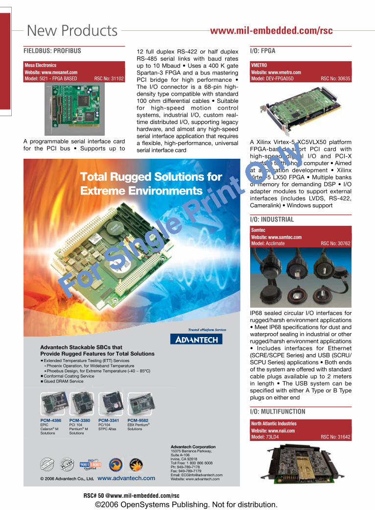
For Single Print Only
New ProductsFieldBuS: PRoFiBuS
MesaElectronicsWebsite:www.mesanet.comModel:5I21-FPGABASED RSCNo:31102
A programmable serial interface card for the PCI bus • Supports up to
12 full duplex RS-422 or half duplex RS-485 serial links with baud rates up to 10 Mbaud • Uses a 400 K gate Spartan-3 FPGA and a bus mastering PCI bridge for high performance • The I/O connector is a 68-pin high-density type compatible with standard 100 ohm differential cables • Suitable for high-speed motion control systems, industrial I/O, custom real-time distributed I/O, supporting legacy hardware, and almost any high-speed serial interface application that requires a flexible, high-performance, universal serial interface card
i/o: FPga
VMETROWebsite:www.vmetro.comModel:DEV-FPGA05D RSCNo:30635
A Xilinx Virtex-5 XC5VLX50 platform FPGA-based, short PCI card with high-speed digital I/O and PCI-X interface to the host computer • Aimed at application development • Xilinx Virtex-5 LX50 FPGA • Multiple banks of memory for demanding DSP • I/O adapter modules to support external interfaces (includes LVDS, RS-422, Cameralink) • Windows support
i/o: induStRial
SamtecWebsite:www.samtec.comModel:Acclimate RSCNo:30762
IP68 sealed circular I/O interfaces for rugged/harsh environment applications • Meet IP68 specifications for dust and waterproof sealing in industrial or other rugged/harsh environment applications • Includes interfaces for Ethernet (SCRE/SCPE Series) and USB (SCRU/SCPU Series) applications • Both ends of the system are offered with standard cable plugs available up to 2 meters in length • The USB system can be specified with either A Type or B Type plugs on either end
i/o: MultiFunCtion
NorthAtlanticIndustriesWebsite:www.naii.comModel:73LD4 RSCNo:31642
RSC# �0 @www.mil-embedded.com/rsc
www.mil-embedded.com/rsc
©2006 OpenSystems Publishing. Not for distribution.
For Single Print Only
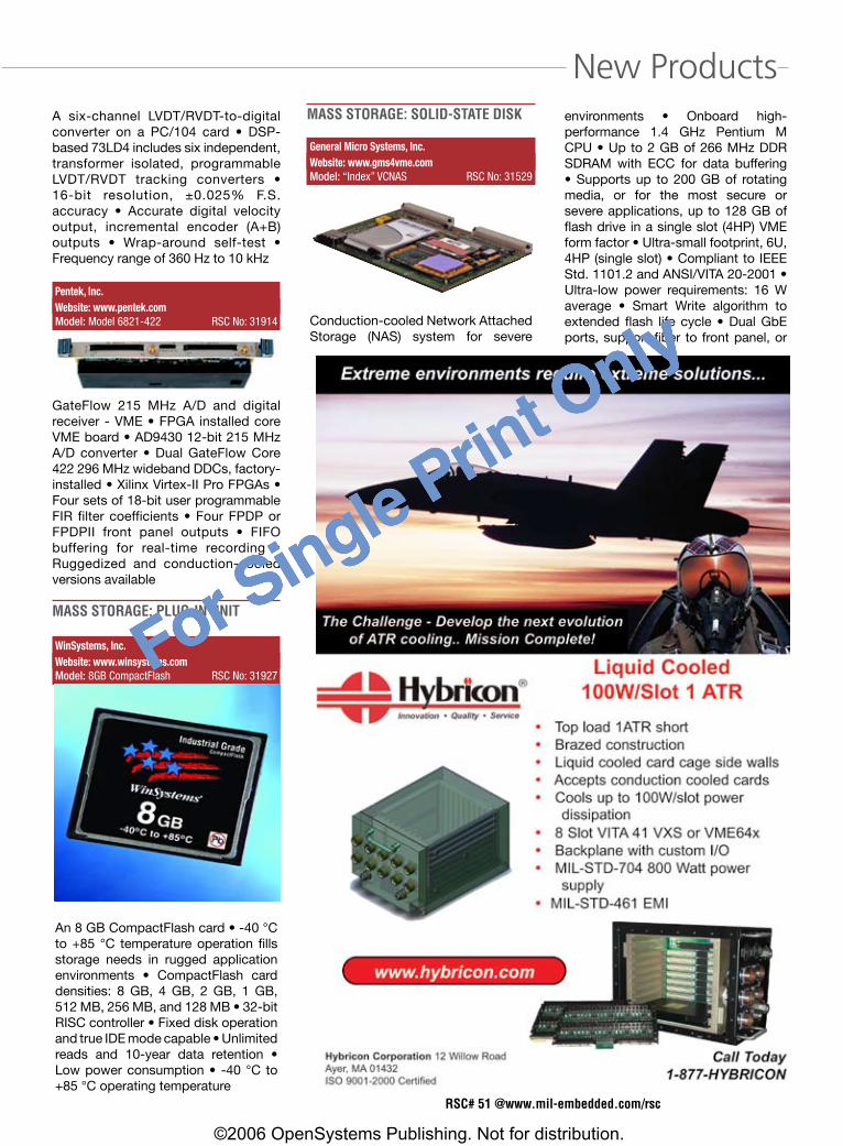
For Single Print Only
New Products
RSC# �1 @www.mil-embedded.com/rsc
A six-channel LVDT/RVDT-to-digital converter on a PC/104 card • DSP-based 73LD4 includes six independent, transformer isolated, programmable LVDT/RVDT tracking converters • 16-bit resolution, ±0.025% F.S. accuracy • Accurate digital velocity output, incremental encoder (A+B) outputs • Wrap-around self-test • Frequency range of 360 Hz to 10 kHz
Pentek,Inc.Website:www.pentek.comModel:Model6821-422 RSCNo:31914
GateFlow 215 MHz A/D and digital receiver - VME • FPGA installed core VME board • AD9430 12-bit 215 MHz A/D converter • Dual GateFlow Core 422 296 MHz wideband DDCs, factory-installed • Xilinx Virtex-II Pro FPGAs • Four sets of 18-bit user programmable FIR filter coefficients • Four FPDP or FPDPII front panel outputs • FIFO buffering for real-time recording • Ruggedized and conduction-cooled versions available
MaSS StoRage: Plug-in unit
WinSystems,Inc.Website:www.winsystems.comModel:8GBCompactFlash RSCNo:31927
An 8 GB CompactFlash card • -40 °C to +85 °C temperature operation fills storage needs in rugged application environments • CompactFlash card densities: 8 GB, 4 GB, 2 GB, 1 GB, 512 MB, 256 MB, and 128 MB • 32-bit RISC controller • Fixed disk operation and true IDE mode capable • Unlimited reads and 10-year data retention • Low power consumption • -40 °C to +85 °C operating temperature
MaSS StoRage: Solid-State diSk
GeneralMicroSystems,Inc.Website:www.gms4vme.comModel:“Index”VCNAS RSCNo:31529
Conduction-cooled Network Attached Storage (NAS) system for severe
environments • Onboard high-performance 1.4 GHz Pentium M CPU • Up to 2 GB of 266 MHz DDR SDRAM with ECC for data buffering • Supports up to 200 GB of rotating media, or for the most secure or severe applications, up to 128 GB of flash drive in a single slot (4HP) VME form factor • Ultra-small footprint, 6U, 4HP (single slot) • Compliant to IEEE Std. 1101.2 and ANSI/VITA 20-2001 • Ultra-low power requirements: 16 W average • Smart Write algorithm to extended flash life cycle • Dual GbE ports, support fiber to front panel, or
©2006 OpenSystems Publishing. Not for distribution.
For Single Print Only

For Single Print Only
New ProductsVITA 31.1 • TCP/IP Offloading Engine (TOE) on both GbE ports • NAS capacity may be extended by daisy-chaining via Ethernet ports • Allows multiple CPU boards with different OS to boot from one NAS unit • Two NAS units may be used to mirror each other for redundant data • Supports HTTP, FTP, TFTP, TELNET, and NFS servers • Support for NFS, FTP, and TELNET client sessions • VME64 support via Tundra Universe II (optional) • Rugged extended temperature range of -40 °C to +85 °C
Mezzanine: CCPMC
AitechDefenseSystems
Website:www.rugged.comModel:M222 RSCNo:31438
A rugged/mil spec, high-density, NAND flash-based PMC mass memory module • Up to 64 GB NAND flash memory in two banks • >45 MBps transfer rate (sustained) • Low power consumption <4 W • PCI Rev. 2.3 compliant supporting 64-bit @ 66 MHz • VxWorks and LynxOS RTOS support with Flash Low Level (FLL) driver • Optional Flash Memory Manager (FMM) for auto wear-leveling, bad block mapping, and so on • Full file system read/write emulation • IEEE 1386-2001 (air-cooled) or VITA 20-2001 (conduction-cooled) • Commercial/military level ruggedization • Vibration and shock resistant
PRoCeSSoR: CeleRon M
BCMAdvancedResearch
Website:www.BCMCOM.comModel:EBC5852-C8 RSCNo:31137
RoHS (lead-free) 5.25" SBC • Operates with a single DC +12 V input • Based
on the Intel 82852GM GMCH and 82801DB ICH4 chipset architectures • Supports Intel Celeron M processor in onboard BGA format • Runs with a 400 MHz FSB and has one 200-pin DDR SODIMM socket that will support up to 1 GB PC2100 non-ECC system memory • Features an 18-bit dual channel LVDS output for LCD panels, one IDE connector, two SATA connectors, and a CompactFlash socket • Features additional I/O including two serial ports, six USB 2.0 ports, one 10/100 Mbps LAN, one GbE interface, and one 32-bit PCI slot • Thermal sensor for hardware monitoring capabilities • Supports the ACPI V2.0 specification • For any application that requires a small footprint, high-performance solution
PRoCeSSoR: PentiuM M
Fastwel
Website:www.fastwel.comModel:FastwelCPC1700 RSCNo:31632
A PC/104-Express format single board computer designed for mission-critical embedded systems • Intel Pentium M processor up to 2.26 GHz and 533 MHz FSB • 1 GB PC4200 DDR2 SDRAM soldered onboard • Four x1 PCI Express expansion interfaces • Two GbE ports • Two independent CRT/LVDS displays • Two Serial ATA channels • Operating temperature: -40 °C to +85 °C
MENMicroElektronikGmbH
Website:www.menmicro.comModel:D601 RSCNo:31924
A conduction-cooled 6U CompactPCI Pentium M SBC • Fanless operation in military, aerospace, and industrial control applications • With either the 1.4 GHz Low Voltage (LV) Pentium M or the 1 GHz Ultra-Low Voltage (ULV) Celeron processors, a temperature range of -40 ºC to +85 ºC is supported • Can be equipped with Intel processors with speeds up to 2 GHz • 32-bit/33 MHz interface to the CompactPCI bus • Can also function as a stand-alone processing unit in bus-less systems • 915GM chipset provides high-speed communication for GbE connectivity and graphics • Two SATA ports • Onboard memory is high-speed Double Data Rate 2 (DDR2) DRAM with access rates of up to 2 Gbps
PRoCeSSoR: PoweRPC
InterfaceConcept
Website:www.interfaceconcept.comModel:MPC7448 RSCNo:30377
MPC7448 PowerPC-based VME64x VITA 31.1 SBC • PowerPC- and PowerQUICC processor-based SBC boards (3U and 6U) • Fast Ethernet and GbE switches (up to 30 ports) • PowerPC processor- and PowerQUICC processor-based Ethernet interface controllers • Synchronous/asynch-ronous serial communication platforms
ACTISComputer
Website:www.actis-computer.comModel:CSBX-3545 RSCNo:31193
52 / FALL 2006 MiLitAry EMBEDDED SyStEMS
www.mil-embedded.com/rsc
©2006 OpenSystems Publishing. Not for distribution.
For Single Print Only

For Single Print Only
New Products3U CompactPCI single board computer • Available for standard convection cooling or rugged conduction cooling critical embedded applications • PowerQUICC III MPC8545E up to 1.2 GHz with up to 1 GB of soldered DDR memory with ECC support • 8 MB of flash memory for the onboard monitor software • 1 GB NAND Flash for data or program storage • Includes an Altera Cyclone II FPGA offering up to 50k Logic Elements, 580 kb of RAM, and 86 embedded multipliers • The FPGA, connected to its own 64 MB of dedicated SDRAM memory, provides additional hardware computational resources to accommodate demanding applications • Two GbE ports for switched buses architectures (blades concept) and a standard 32-bit CompactPCI bus interface for local extensions • Security engine • Three-level ruggedization levels support • Linux and VxWorks RTOS support
HuntEngineering
Website:www.hunteng.co.ukModel:RTG004 RSCNo:30411
A USB-connected embedded PowerPC system • User-programmable Xilinx XC2VP7 FPGA with embedded PowerPC • 256 Mb of DDR SDRAM connected as two banks of 32 Mx32 @ 200 MHz • 16 Mb of flash memory for PowerPC code storage • 30 bits programmable digital I/O • High-speed (480 Mbps) USB 2.0 connection to a host PC • Can be used as a stand-alone board for embedded systems • FPGA can be configured via USB, Xilinx JTAG cable, or from onboard PROM • Single 5 V power supply required – 20 W mains power supply unit included • Hunt Engineering host API supported for Windows 2000 and XP and Linux • FPGA and DSP loading, resetting, and data exchange all performed with simple-to-use software interface • Optional expansion via HERON module slot
ShelF and MeChaniCal CoMPonentS
DatatronicsDistribution
Website:www.datatronics.comModel:DR365-1-2 RSCNo:31626
Miniature surface mount inductors that provide effective EMI protection
for applications • RoHS compliant • Ultra-thin, featuring a seated height as low as 0.047" (1.2 mm) above the printed circuit board depending on the inductance value required • Ideal for a wide range of portable, compact, and miniature devices such as PDAs, mobile phones, and portable hard drives • Wide inductance range from 3.3 µH to 100 µH (at 100 kHz, 0.1 V), with a DCR range from 0.11 to 2.8 ohms and a maximum rated current from 0.20 to 1.2 amps • Rugged operating temperature range of -20 ºC to +80 ºC
RSC# �� @www.mil-embedded.com/rsc
©2006 OpenSystems Publishing. Not for distribution.
For Single Print Only

For Single Print Only
Crosshairs Editorial By Chris A. Ciufo
Intel’s latest crop of desktop and server CPUs is not only likely to reclaim the performance crown from rival AMD, there’s also a chance they’ll steal sockets from Freescale’s PowerPC processors in embedded. Long a high-performance favorite for tasks such as control loops and radar processing, the MPC74xx “G4” PowerPC with AltiVec engine has been riding a success curve for more than 10 years. CompactPCI, VME, AdvancedMC, PMC, and other form factor boards rely on the PowerPC more frequently than any other General Purpose Processor (GPP) because of its stellar GFLOP benchmarks in dual- and quad-CPU configurations.
Take a look at just about any DSP board in the market and you’ll likely find a PowerPC (or two) and some kind of FPGA. Current generation MPC7448 PowerPCs are just now being deployed, and I’ve reviewed nearly six new product announcements in the past couple of months – from vendors including Curtiss-Wright Controls Embedded Computing, Aitech, Extreme Engineering, and Momentum Computer (affiliated with Mercury Computer Systems). These companies undoubtedly chose Freescale’s latest single-core PPC as next-in-line on the PowerPC road map because the current “Book E” Power Architecture scales nicely and allows some form of code migration from earlier versions that date all the way back to IBM’s PowerPC 601.
But this may soon be ancient history because Intel’s dual-core Xeon Ultra Low Voltage (ULV) server CPU is offering performance-per-watt numbers that rival the MPC7448. According to Mercury Computer Systems in their recent E-cast “Bringing a Quad-Core Intel Server to Embedded Applications” (www.opensystems-publishing.com/ecast), it’s now possible to stuff two dual-core Xeon ULVs on a single 6U board and still be within easy reach of air- and conduction-cooling. A single Xeon ULV contains two cores running at 1.66 GHz but consumes only 15 W. This compares very favorably to a single core Freescale 7448 running at 1.4 GHz consuming 10 W. In effect, that second core consumes only 50 percent more power.
Moreover, while not really designed for high-end signal processing systems using Symmetrical Multiprocessor (SMP) architectures, two dual-core Xeons – unlike previous Intel CPUs such as Pentium Ms or even Intel’s latest Core Duo CPU – bolt together nicely via Intel’s E7520 Northbridge. According to Mercury, this configuration yields an easily programmed four-way SMP setup with 4x the previous Intel processing density in one 6U slot (see Figure 1). The dual-core Xeons share an onboard L2 cache while maintaining good memory bandwidth with off-chip DDR2-400 dual channel off-chip memory.
Even better, the Northbridge has ample I/O, including PCI Express, which facilitates handy interboard (or internode) communication. Mercury estimates that the two CPUs, Northbridge, and SDRAM in a four-way SMP architecture would consume a total estimated 75 W on a single 6U board.
What’s the big deal, you say? Existing PowerPC boards consume a bit less power, are ideally suited for SMP, and already have an established code base. That’s true. The big deal is that the ULV Xeon is now squarely in PowerPC territory, and Intel has a road map of additional processors – including quad cores – that stretches out from here to eternity.
Intel is so focused on cranking out more performance-per-watt at commodity prices that embedded designers simply must consider Intel’s offerings as a serious threat to the PowerPC. And when you couple the enormous code base available for Intel Architecture processors, including applications you run on your desktop, CPUs like the dual-core Xeon ULV are bound to start showing up in military embedded systems within six months.
Chris A. Ciufo Group Editorial Director
Intel Xeons encroach on PowerPC’s territory
5� / FALL 2006 MiLitAry EMBEDDED SyStEMS
Dual-Core Xeon
CPU CPU
L1 L1
L2
Dual-Core Xeon
CPU CPU
L1 L1
L2
IntelE 7520
Memory
Memory
I/O I/O
PCI ExpressFigure1
©2006 OpenSystems Publishing. Not for distribution.
For Single Print Only
For Single Print Only
Now a part of GE Fanuc Embedded Systems
© 2006 GE Fanuc Embedded Systems, Inc. All rights reserved.
Imagine what we can do for you now.Our vision is to offer you the kind of products and services you’ve only dreamed of.
GE Fanuc Embedded Systems
If you could build the perfect embedded products company, it might be something like the one we’ve created by combining the imagination, energy, and expertise of the people at GE Fanuc Embedded Systems, Condor Engineering and SBS Technologies.
It would be a company with the experience, resources and courage to develop truly innovative products—which is a cornerstone of the General Electric Company. It would be a company with a wide range of available products—everything from avionics and industrial controls
to networking, communications, and fully integrated systems—which is exactly what Condor Engineering, SBS Technologies, and GE Fanuc bring to the table.
By creating this new company, we’ve taken a giant step toward our vision of a different and better kind of embedded company. So we invite you to open your mind and let your imagination run wild. Because our goal is to be right there with you helping make your inspirations into realities.
www.gefanucembedded.com
Intel Xeons encroach on PowerPC’s territory
RSC# �� @www.mil-embedded.com/rscRSC# �� @www.mil-embedded.com/rsc
©2006 OpenSystems Publishing. Not for distribution.
For Single Print Only
For Single Print Only
Embedded systems are about to take a major leap forward. Boards and systemsbased on the VPX and VPX-REDI standards redefine the limits of performance and ruggedization with unprecedented backplane I/O connectivity and greatlyimproved thermal management. And Curtiss-Wright is right where you'd expect,taking the lead with innovative VPX Single Board Computers and Digital SignalProcessing engines to launch the new era of switched fabric-based embeddedcomputing. The next phase has begun. Curtiss-Wright is ready.
Innovation In Motion
WWW.CWCEMBEDDED.COM
G E T READY F O R T H E NEXT PHASEI N EMBEDDED COMPUTING.
&
RSC# �� @www.mil-embedded.com/rsc
©2006 OpenSystems Publishing. Not for distribution.
For Single Print Only