the effect of a second order chemical reaction on the
TRANSCRIPT

Louisiana State UniversityLSU Digital Commons
LSU Historical Dissertations and Theses Graduate School
1966
The Effect of a Second Order Chemical Reactionon the Absorption of Methyl Mercaptan in aLaminar Liquid Jet.Joseph Earl LandryLouisiana State University and Agricultural & Mechanical College
Follow this and additional works at: https://digitalcommons.lsu.edu/gradschool_disstheses
This Dissertation is brought to you for free and open access by the Graduate School at LSU Digital Commons. It has been accepted for inclusion inLSU Historical Dissertations and Theses by an authorized administrator of LSU Digital Commons. For more information, please [email protected].
Recommended CitationLandry, Joseph Earl, "The Effect of a Second Order Chemical Reaction on the Absorption of Methyl Mercaptan in a Laminar LiquidJet." (1966). LSU Historical Dissertations and Theses. 1203.https://digitalcommons.lsu.edu/gradschool_disstheses/1203

This dissertation has been microfilmed exactly as received 67—1170
LANDRY, Josep h E arl, 1936- THE EFFEC T OF A SECOND ORDER CHEMICAL REACTION ON THE ABSORPTION OF METHYL MER- CAPTAN IN A LAMINAR LIQUID JE T .
Louisiana State U n iversity , P h .D ., 1966 Engineering, chem ical
University Microfilms, Inc., Ann Arbor, Michigan

THE EFFECT OF A SECOND ORDER CHEMICAL REACTION ON THE ABSORPTION OF METHYL MERCAPTAN IN A LAMINAR LIQUID JET
A Dissertation
Submitted to the Graduate Faculty of the Louisiana State University and
Agricultural and Mechanical College in partial fulfillment of the requirement for the degree of
Doctor of Philosophy
in
The Department of Chemical Engineering
byJoseph Earl Landry
B.S., University of Southwestern Louisiana, 1958 M.S., Louisiana State University, 1963
August, 1966

ACKNOWLEDGEMENTS
The author expresses his sincerest thanks and appreciation to
Professor Jesse Coates, for his direction, assistance, and under
standing. The advice of the other members of the Faculty in Chemical
Engineering is also gratefully acknowledged. The assistance of the
National Council for Stream Improvement (of the Pulp, Paper, and
Paperboard Industries), particularly the kind understanding of Mr.
Herbert Berger, is recognized and appreciated. Deserving particular
mention are, Mr. John Miller, for his assistance in evaluation of
the equipment, Mr. L. M. Carpenter for his assistance in fabricating
the experimental equipment, the staff of the University's Computer
Research Center for their assistance in processing the mathematical
computations, and Mrs. Lee M. Potzner and Mr. Norman D. Hyett for
their assistance in the preparation of the manuscript.

TABLE OF CONTENTS
PAGE
Abstract ix
Chapters
I. Introduction . . . . ■...................................... 1
1. The Problem..........................................2. Technical Approach . . . . ....................... 5
II. Review of Related R e s e a r c h ................................. 10
1. Theoretical Studies .................................. 102. Studies in a Laminar Liquid J e t ...................... Ik3. Extension to Large Scale Equipment ................ 15
III. T h e o r y ....................................................... 18
1. Fick's L a w ............................................ 182. Molecular Diffusion ................................. 22
a. G a s e s ............................................ 22b. Liquids.......................................... 2k
3. Eddy D i f f u s i o n ........................................27*t. Interphase Mass Transport.............................27
a. Two Film T h e o r y .................................. 28b. Penetration Theory ............................ 29
5. Interfacial Mass Transfer Accompaniedby Chemical Reaction ............................. 30
IV- Experimental W o r k ............................................ k2
1. Laminar Liquid J e t ................................... k22. Diameter Measurements ............................... 503. Test M a t e r i a l s ........................................52k. Calibration Procedures ............................. 525. Experimental Procedures ............................. 5k
* * tn i

Chapters PAGE
V. Analysis of R e s e a r c h 56 ~
1. Fluid Mechanics * ■ ; ............................. 562. f . ration T h e o r y ................................ 583- Penetration Theory with Chemical Reaction . . . . 684. Infinitely Rapid Chemical R e a c t i o n ............ 795. Empirical Correlation of Numerical Solutions . . 816. Extension to Packed Absorber D e s i g n ............ 8**
VI- Discussion of R e s u l t s ....................................... 95
1. Carbon Dioxide and W a t e r ........................ 952. Sulfur Dioxide and W a t e r ........................ 1003- Methyl Mercaptan and Water ......................... 1051*. Methyl Mercaptan Absorption in Aqueous
Sodium Hydroxide Solutions ...................... 108a. Ionic Reactions * • * . * . . . * * • . * * 108b. Estimate of Forward Reaction Rate-
Constant 1125. Extension of Theory to Pilot Scale Absorber . . . 116
VII Conclusions and Recommendations ...................... 124
N o t a t i o n ............................................ 128
Selected Bibliography .......................................... - • 132
Appendi ces
A. Calculation of Ionic Diffusivities ...................... 137
B. Carbon Dioxide and Water D a t a ................................ 140Sulfur Dioxide and Water D a t a .................................141
C. Methyl Mercaptan and Water D a t a ..............................11*2
D. Methyl Mercaptan and Sodium Hydroxide AbsorptionData . . . a . * . * * . . . . . . . . . . . * . * . 143
Calculation of Mass Transfer Coefficients ............... 145Effect of Hydroxyl Concentration on Absorption
C o e f f i c i e n t .................................................... 147
E. Evaluation of the Parameter $ F r o m the EmpiricalCorrelation Equation ..................................... 148
F. Derivation of Integrated Equations for PackedTower Height (Integral Method).............. 153
iv
Appendices PAGE
G. Statement List of Computer Program forPacked Absorber Calculations byDifferential Method ...................................... 158
H. Numerical Answers From Computer Program ................ 162
I. Sample Calculations.................. 189
J. Rotameter Calibration ...................................... 175
Autobiography ...................................................... 176
v

LIST OF TABLES
TABLE PAGE
I. ABSORPTION SYSTEMS WITH CHEMICAL REACTION ............. 3
II. ~EST OF BUBBLE FILM F L O W M E T E R ........................... 101
III. REACTIONS RATE C O N S T A N T S .................................. 115

LIST OF FIGURES
FIGURE PAGE
1. SCHEMATIC DIAGRAM OF FICK'S DIFFUSIONEXPERIMENT............................................. 20
2. CONCENTRATION IN DOUBLE FILM DURING ABSORPTIONOF METHYL MERCAPTAN BY AQUEOUS SODIUM HYDROXIDE . . 34
3* THEORETICAL SOLUTION FOR PENETRATION THEORYACCOMPANIED BY IRREVERSIBLE SECOND ORDER CHEMICAL REACTION...................................... 41
4. PHOTOGRAPH OF LAMINAR JET ABSORPTION APPARATUS . . . 44
5. ENGINEERING DRAWING OF LAMINAR J E T ................... 45
6A. PHOTOGRAPH OF LIQUID JET . . ......................... 46
6B. PHOTOGRAPH OF ORIFICE ASSEMBLY ....................... 47
7. SCHEMATIC FLOW DIAGRAM OF ABSORPTION APPARATUS . . . 48
8. CURVATURE OF LIQUID JET TO S C A L E ..................... 51
9. VELOCITY PROFILE DEVELOPMENT IN A LAMINARLIQUID J E T ............................................. 57
10. DIAMETER OF LAMINAR LIQUID JET - FLOW2.35 cc./sec............................................ 59
11. DIAMETER OF LAM INAR LIQUID JET - FLOW3. 60 cc. /sec............................................ 60
12. DIAMETER OF LAMINAR LIQUID JET - FLOW4. 15 cc. /sec............................................ 61
13. ONE DIMENSIONAL COORDINATES FOR THE DERIVATION FICK'S SECOND LAW LEADING TO THE PENETRATIONTHEORY SOLUTION ...................................... 63
v i i

FIGURE PAGE
Ik. THEORETICAL SOLUTION FOR PENETRATIONTHEORY ABSORPTION WITH SECOND ORDERIRREVERSIBLE CHEMICAL REACTION ......................... 80
15- THEORETICAL SOLUTION FOR AN INFINITELY FASTSECOND ORDER CHEMICAL REACTION ......................... 82
16. REPRESENTATION OF THE THREE ABSORPTION ZONES IN A PACKED TOWER IN WHICH THE REACTIONA+B - AB TAKES PLACE AT AN INFINITELY RAPIDR A T E ......................................................... 86
17. REPRESENTATION OF REACTION ZONE IN PACKEDA B S O R B E R ..................................................... 90
18. PACKED PILOT ABSORBER RESULTS - FRACTIONABSORBED UNDER CHANGING LIQUID FEED CONCENTRATION OF SODIUM H Y D R O X I D E ............................ 9k
19. RATE OF ABSORPTION OF CARBON DIOXIDE INWATER. JET WITH PARABOLIC VELOCITY PROFILE . . . . 97
20. ABSORPTION OF CARBON DIOXIDE IN WATER A T 25°C . . . 99
21. ABSORPTION OF SULFUR DIOXIDE IN WATER AT 25°C . . . 102
22. SOLUBILITY OF SULFUR DIOXIDE IN W A T E R ......... 10*t
23. ABSORPTION OF METHYL MERCAPTAN IN WATER AT 25°C . . 107
2k. ABSORPTION COEFFICIENTS OF METHYL MERCAPTAN INAQUEOUS SOLUTIONS OF SODIUM HYDROXIDE ............... 109
25. EFFECT OF SODIUM HYDROXIDE CONCENTRATION ONABSORPTION R A T E .................../ ..................... 110
26. ABSORPTION RATE COMPARED WITH THEORETICAL SOLUTION FOR INFINITELY FAST SECOND ORDERR E A C T I O N ..................................................... 113
27. ESTIMATION OF FORWARD REACTION RATE CONSTANT . . . . Ilk
28. THEORETICAL SOLUTION FOR PACKED ABSORBER ............. 121
v i i l

ABSTRACT
Present knowledge in the field of gas absorption with simultaneous
chemical reaction has not been advanced to the point where commercial
absorbers can be designed routinely. Pilot scale studies can not be
scaled up using the conventional concepts of physical gas absorption,
unless the process is gas phase limiting throughout the packed absorber.
A review of the literature indicates the need for additional experi
mental data in the absorption of methyl mercaptan in aqueous sodium
hydroxide solutions. These data are needed for air pollution control
in the paper industry. Further, there is need for testing the mathe
matical solutions published for the penetration theory with chemical
reaction and extension of these concepts for the design and scale-up
of equipment.
The laminar liquid jet was chosen to obtain the basic absorption
data on the methyl mercaptan-sodium hydroxide system, because its
unique fluid dynamic and operating characteristics allow the use of
the penetration theory for the description of the process. Further,
the absorption data measured with the laminar jet can be analyzed
to determine reaction rates for a postulated reaction mechanism.
The liquid jet formed by the diaphragm orifice is cylindrical
and the boundary-layer effects caused by the orifice walls are
minimal. Beyond the section of boundary layer retardation the jet

diameter can be predicted by the equations of motion for a frictionless
jet.
The diffusion coefficients of carbon dioxide, sulfur dioxide, and
methyl mercaptan in water at 2*>°C were measured. The gas absorption
rates in the liquid jet follow the penetration theory results over
the studied contact time range of 2-5 to 30 milliseconds. The
measured values of the diffusion coefficients were comparable with
reported results.
The absorption of methyl mercaptan in aqueous solutions of sodium
hydroxide, as measured in the laminar liquid jet apparatus, were corre-
lated by the penetration theory solutions for an infinitely fast irre
versible reaction. The diffusion of the hydroxyl ion determines the
effect on the mass transfer rate, which would differ significantly
if the sodium hydroxide diffused as a molecular specie with its salt
diffusivity.
The reaction of the dissolved methyl mercaptan with the hydroxyl
ions is a very fast second order irreversible reaction with a forward5rate constant in the order of 10 liters/gram-moles-second. The
kinetics of this equation was inferred by extension of the penetration
theory solutions in the parametric range studied.
The absorption of dilute gas solutions of methyl mercaptan in
aqueous sodium hydroxide contacted in a packed absorber was predicted
by a method of calculation based on the penetration theory. Knowing
the reaction kinetics and the physical absorption constants the height
of chemical absorbers can be calculated.
x

Dedicated to
my teachers,
my parents,
and my wife.
xi

CHAPTER I *INTRODUCTION
Gas absorption is defined as an operation in which a gas is
contacted with a liquid for purposes of dissolving one or more compo-
nents of the gas and to provide a solution of these in the liquid.
The transfer of the gaseous solute is a diffusional process. The
molecules of the gas being absorbed have to pass by diffusion through
the gas phase, cross the interface between gas and liquid, and then
pass into the liquid phase. The molecules can move either by molecular
diffusion, which is a slow process, or by eddy diffusion, a much faster
process in which appreciable amounts of the liquid or gas move as in
mixing. In order to increase the preferential solubility of the gas
in the liquid, a compound is often added to the solvent which will
react or otherwise form strong chemical bonds with the solute. The
process is called chemical absorption or absorption accompanied with
a chemical reaction.
The unit operation of chemical absorption is commercially important.
Practical problems include the recovery of valuable or nuisance gases
by continuous contact with a chemically active solvent. The selection
of a solvent is based on economics. Solvent regenerabi1ity, costs of
the solvent, quantity of solute used, and utilization of the spent
solvent as a common process stream are factors to be considered.

2
Absorption systems with chemically reactive solvents are very
important in the field of air pollution control and the chemical
process industries. Typical problems of commercial importance are
listed in Table 1. Note that most of the gaseous solutes listed in
the table are also classed as air pollutants.
The need for controlling gaseous emissions to the environment is
well documented and is becoming a national problem. Recent reports,
such as the one by the President's Science Advisory Committee,* list
the compounds which are of concern. Among gases which deterioate
materials and degrade the environment are sulfur dioxide and hydrogen
sulfide. Sulfur dioxide, accelerates the weathering of buildings and
monuments. Urban concentration levels are high enough to endanger
health. Hydrogen sulfide darkens paints containing lead and mercury,
and also produce an unaesthetic air environment. Odors from organic
sulfides and mercaptans also are nuisance.
The climatic effect of pollution is of some concern. Carbon
dioxide is being added to the earth's atmosphere by the combustion2of fossil fuel at the rate of 6 billion tons a year. The report's
projection for the year 2000 is a 25% increase in C0^ over the present concentration level. It is claimed that this will modify the heat
balance of the earth to such an extent that climatic changes will be
chaotic and uncontrollable.
^President's Science Advisory Committee, Restoring the Quality of Our Environment, Report of the Environmental Pollution Panel, November 1965.
2 | b i d . , p. 9.

3
TABLE I
ABSORPTION SYSTEMS WITH CHEMICAL REACTION3
Solute Gas Reagent
CO2 CarbonatesCO2 HydroxidesCO2 EthanolaminesCO Cuprous amine complexesCO Cuprous ammonium chlorideS02 Ca(OH) 2S02 Ozone " H 20S02 HCrO^S02 — KOHci2 h 2oCl2 FeCl 2H2S Ethanol aminesH2S HydroxidesH2S Pe(OH) j
— so3 h2so4c z h ^ KOHC2Hjf Trialfcyl phosphatesNO FeSO^NO Ca(OH)2NO H 2S04no2 h 2o
3A. J. Teller, "Absorption with Chemical Reaction," Chemica1 Enqineering, July 11, 1961, p. 111.

k
The highest priority will be given to the investigation of effects
and control measures pertaining to the following compounds: sulfur
dioxide, carbon monoxide, oxides of nitrogen, carcinogens, peracyl*nitrates, gasoline additives including lead and asbestos particles.
Compounds with high priority are: benzene and homologues, alkyl
nitrates, alkyl nitrites, aldehydes, ethylene, pesticides, auto
exhaust, amines, mercaptans, hydrogen sulfide, and beryllium particles.
While this all-encompassing report covers some distant goals, it -
points out the areas which will concern chemical engineers for the years
ahead. It is a chemical engineering problem which is national in sqope.
1. The P rob1em
The pulp and paper industry produces three important pollutants
previously mentioned; sulfur dioxide, hydrogen sulfide, and methyl
mercaptan. The compounds are by-products of combustion, hydrolysis,
and delignification of wood with sodium hydroxide - sodium sulfide
solutions. The removal of methyl mercaptan from process emissions
will reduce the air pollution problems of the industry.
The subject of this study, sponsored by the National Council
for Stream Improvement (of the Pulp, Paper, and Paperboard Industry)
is the effect of chemical reaction on the absorption of methyl
mercaptan in aqueous sodium hydroxide solutions. The scope of the
study included the determination of the reaction mechanism, the rate
of reaction, and the mass transfer variables. These variables were
Report of the Environmental Pollution Panel, oj>. cit. , p. 66.
5
projected to pilot scale absorption systems as a demonstration of
the design technique required for commercial application.
2. Technical Approach
The previous paragraphs cite the need for more efficient absorbers
and makes it imperative to study the absorption processes from a funda
mental point of view. The technology of chemical engineering is at a
point where the design of absorbers for physical absorption is a nearly
routine matter, when certain physical constants have been determined.
Absorption with chemical reaction is much more complex and the design
of absorbers not routine. Absorbers can be designed which will "work",
but their performance cannot always be predicted. Goals of engineering
studies should be the design of large scale equipment based on funda
mental principles. This can be accomplished by the measurement of
important physical variables and the development of a mathematical
model (sets of predictive mathematical relationships) which can be
used to describe the operation of the system.
The most widely used model for the interpretation of absorber
performance is the Whitman® two film theory.^ This model relies on
the following series of assumptions:
1. Steady state conditions exist in both phases.
2. Rate of transfer is proportional to the concentration
gradient.
®W. G. Whitman, “The Two Film Theory of Gas Absorption," Chemical and Metallurgical Engineering, XXXIX, July 23, 1923, p- 1*̂ 6.
£This was later used to develop calculation techniques involving
heights and number of mass transfer units.

6
3. Equilibrium exists between the liquid and vapor at the
interface with no interfacial resistance to flow.
1*. Hold up at the interface is negligible.
These assumptions led to the now familiar equations:
Na “ KQa (PG " ?*) (1-la)
.= K^a (c* - c^) (1 - lb)
= kGa P̂G " p i^ (1-lc)
= k°a (c. - cL) (1-ld)
These equations show an additivity of resistance similar to that
used in heat and electrical conduction developments. The individual
resistances are effectively combined into a single coefficient.
As a result of a search for a more realistic model of individual
resistances, Higbie^ developed the penetration theory. It removes
the limitations (1) and (4) which are listed above, since it considers
gas absorption into a quiescent liquid pool as an unsteady state
mechanism. It has been found applicable to wetted-wall and packed
columns, and was used recently to improve correlation the distillation
7R. Higbie, “The Rate of Absorption of a Pure Gas into a Still Liquid during Short Periods of Exposure,*1 A. I. Ch. E. Journal, XXXI (1935), p. 365.

7
8tower tray efficiencies. The difference in the theories concerns the
and not to the first power of the diffusion coefficient as the two
film theory predicts.
If normal physical absorption were the only mechanism encountered
the methods would be adequate using either the two film theory or the
penetration theory. But in chemical absorption, the overall mass
transfer coefficient varies widely because it is dependent on the
gG. A. Hughmark, "Point Efficiencies for Tray Distillations,"
Chemical Engineering Progress, LXI, July 1965t P* 97-qT. K. Sherwood and F. A. L. Hollaway, "Performance of Packed
Towers - Liquid Film Data for Several Packings," Transactions of the American 1nstitute of Chemical Engineers, XXXVI (19^0), p. 39.
dependence of the absorption coefficient on the diffusivity. The film
theory indicates that;
( 1- 2)
and the penetration theory's equivalent coefficient is;
(1-3)
qwhere t' is the time of contact. In a study by Sherwood and Hollaway,
the actual behavior in a packed tower was shown to be:
(1-10
8
liquid phase reactant concentration; unless the major resistance to
mass transfer is in the gas phase. The liquid phase resistance is a
function of the reaction kinetics, which in turn may be limited^by the
rate of reaction or by the diffusion of the liquid phase reactant.*®
For systems in which the chemical reaction proceeds at a rate of the
same magnitude as the mass transfer rate, the penetration theory is
the best model. For very rapid irreversible reactions, the problem
becomes a mass transfer problem where the transfer of liquid phase
reactant must also be considered.
The problem of predicting the effect of simultaneous liquid-
phase chemical reaction was approached early. Hatta** formulated
a useful theory for describing absorption with very fast chemical
reaction. This is a limiting case and not as general as the pene-12 13tration theory approach. Sherwood and Pigford have reviewed
the application of the two theories.
One of the drawbacks to the use of the penetration theory with
chemical reaction is the complexity of the mathematical solutions.
*®J. H. Perry, Chemical Engineers1 Handbook, (4th Edition; New York: McGraw-Hill, Inc., 1963), 14-19.
**S. Hatta, Technical Reports; Tohoku Imperial University, X (1932), p. 119, from Sherwood and Pigford (1952).
12P. L. T. Brian, J. F. Hurley, and E. H. Hasseltine, "Penetration Theory for Gas Absorption Accompanied by a Second Order Chemical Reaction," A. I. Ch. E. Journal, VII (1961), p. 227-
*^T. K. Sherwood and R. L. Pigford, Absorption and Extraction, (2nd Edition; New York: McGraw-Hill, I n c ~ 1952) , pp. 317“339) •
9
Analytical solutions exist for two limiting cases, 1) pseudo first
order reaction and, 2) second order, infinitely fast, irreversible
reactions. For reaction rates other than those which are infinitely
fast, the problem requires numerical solutions which are feasible only
on high speed electronic computers with a relatively large memory.
Within the last decade, the advent and general use of such machines
has produced some general solutions. These are published for a wide
range of parameters but are somewhat limited because of the small
number of solutions given. Empirical correlations for these solutions
have been developed. These solutions have been confirmed in a few
cases. Vivian and K i ng^ cites the need for additional confirmation
of theory by means of experimental research.
13J. E. Vivian and C. J. King, Absorption and Disti H a t ion. Ch. 9 Vol. I, of Modern Chemical Engineering, ed. A. Acrivos (New York: Reinhold, Inc., I960).

CHAPTER II
REVIEW OF RELATED RESEARCH
Although extensive work has been reported on absorption with
chemical reaction in packed towers, only the area concerning models
of known fluid dynamics will be considered as related research.
A summary of published theoretical results on large scale chemical
absorption will be given. The divisions of the related research
area are patterned after Vivian and King* who have prepared the
most recent compendium on gas absorption and distillation.
Vivian and King summarize the status of absorption theories and
cites the following: 1) controlled absorption studies with chemical
reaction are of value in providing basic mechanism information in
chemical kinetics, 2) there is a need for testing the mathematical
solutions given for the penetration theory approach, and 3) there is
a need for extension of theory to large scale equipment. The following
sections summarize the literature which is pertinent to this investi
gation.
1. Theoretical Studies2The text by Sherwood and Pigford contains, in Chapter 9* the most
*J. E. Vivian and C. J. King, Absorption and Distillation, Ch. 9, Vol. I , of Modern Chemical Engineerinq, ed. A. Acrivos (New York: Reinhold, Inc., 19&0).
2T. K. Sherwood and R. L. Pigford, Absorption and Extraction,(2nd Edition; New York: McGraw-Hill, Inc., 1952), pp. 317—339-
10

11
extensive summary of absorption accompanied by chemical reaction.
The theoretical analysis has been expanded in recent years since the
publication of the text, but it serves as a basis for understanding
the steady state and unsteady state diffusion with chemical reaction.
Application of the theory to large scale equipment could be updated,
since some numerical solutions have been published in the last three
years.
A more modern book by Bird, Stewart, and Lightfoot^ include the
basic concepts and the analytical solutions for two limiting cases of
chemical absorption; pseudo first order and second order infinitely
fast. The presentation of the mathematical derivation is lucid but1
the breadth of treatment of the subject was necessarily limited.IfLevenspiel's text on reaction engineering covers gas absorption
with chemical reaction. The author uses a sample calculation of a
packed tower to show the usefulness of the Hatta film theory, which
he claims is accurate enough for packed tower design.
Many excellent papers have been published on the general theory
of chemical absorption. The treatment by Danckwerts^ adequately
covers the subject while expanding on the use of the surface renewal
theory. Danckwerts cited the need for improvement of the solutions
since they had been good only for approximation and rough estimates.
R. B. Bird, W. £. Stewart, and E. N. Lightfoot, Transport Phenomena (New York: John Wiley and Sons, Inc. , I960).
V A. Levenspiel, Chemi cal React ion Engineering. (New York:John Wiley and Sons, l n c ~ 1962) , p. 532.
^P. V. Danckwerts, "Gas Absorption Accompanied by Chemical Reaction," A. I. Ch. E. Journal, I (1955) » p* **56.
12
Conventional absorption treatments fail because only two parameters,
and area are considered. Additional data on mechanism and physio-
chemical data should be coupled with mass transfer work. Danckwerts
recommends that agitated liquid absorption work should be accompanied
with measurement of transient absorption in the same liquids to remove
many of the uncertainties present in the literature.
Toor and Chiang^ discuss the similarity between the solutions
of the film theory and penetration theory despite the very different
pictures of the diffusion process given by the two models. For very
fast reactions the writers propose the use of an effective diffusivity
which represents the effect of reaction on absorption. The effective
diffusivity is dependent on the liquid reactant concentration and
offers no apparent usefulness over the solutions discussed below.
Huang and Kuo7 have presented a general absorber model for first
order irreversible chemical reaction. The authors used dimensionless
groups to incorporate the film, penetration, and surface renewal theory
in an absorber model. The technique should prove very useful in
extension to large scale equipment when the reaction is first order,
or pseudo first order. The authors state that with accurate values
of physical absorption coefficients the effect of reaction on mass
transfer rate can accurately be predicted.
^H. L. Toor and S. H. Chiang, "Diffusion-Controlled Reactions,,r A. I. Ch. E. Journal, V (1959), p. 339.
7C. Huang and C. Kuo, “General Mathematical Model for Mass Transfer Accompanied by Chemical Reaction," A . 1.Ch.E. Journal, IX (1963), p. 161.

13
Considering the existence of two analytical solutions for limiting
cases, there is much need for some generalized solutions describing
moderate rate, second order reactions. The development of numerical
solutions for second order non-linear partial differential equations
became feasible with the development of high speed digital computersQ
with large memory cores. Brian, Hurley, and Hasseltine have published
a solution to the penetration theory for a second order irreversible
reaction. The solution of the equations, which will be described in
Chapter IV, are presented in the form of generalized curves. The
usefulness of the numerical solutions to the penetration theory wasq
extended when Brian published the results for a general order kinetic
reaction. The use of a dimensionless parameter, M, which is the
function of the reaction rate constant and the contact time, renders
the solution insensitive to the order of the reaction. Therefore,
the generalized plots are versatile for any order. Four plots are
presented which cover three initial liquid phase reactant concen
trations, with each plot covering several orders of reaction. The
practical or useful result of all these solutions is a correlative
equation which can be used to interpolate or to predict the numerical
solutions with very good accuracy.
gP. L. T. Brian, J. F. Hurley, and E. H. Hasseltine, "Penetration
Theory for Gas Absorption Accompanied by a Second Order Chemical Reaction," A. I. Ch. E. Journal, VII (1961) , p. 227-
gP. L. T. Brian, "Gas Absorption Accompanied by an Irreversible Reaction of General Order," A. I. Ch. E. Journal, X (196*0, p- 5-

14
The effect of counterionic diffusion has been estimated by Brian,
Baddour, and Matiatos. ̂ The authors cite the importance of diffusion
of ionic species. The error is considerable if one considers the
diffusion of molecular species, when only the cation or anion diffuses
and participates in the reaction. The diffusion of reactant ions are
retarded by counter diffusion of product ions and by the temporary
electric field established by the charged particles. Vinograd and11 12 McBain, and Sherwood and Wei reported also on these effects.
13Brian, et al. have presented an approximate solution which can be
used to predict the effective diffusivity of the solute ion. It
differs from a true solution by a maximum of 4%.
2. Studies in a Laminar Liquid Jet
““Laminar liquid jets have been used for quite some time to measure
surface tension effects. One of the earliest publications related to
this study on laminar liquid jet in applications to mass transfer was14by Scrivens and Pigford. The authors reported on the fluid dynamics
^P. L. T. Brian, R. F. Baddour, and 0. C. Matiatos, "An Ionic Penetration Theory for Mass Transfer with Chemical Reaction," A.I.Ch.E. Journal. X (1964), p. 727*
**J. R. Vinograd and J. W. McBain, "Diffusion of Electrolytes and of the Ions in Their Mixtures," Journal of the American Chemical Society. LXI11 (1941), p. 2008.
12t . k . Sherwood and J. C. Wei, "Ion Diffusion in Mass Transfer Between Phases," A. I■ Ch. E. Journal. I (1955). p. 522.
13Brian, Baddour, and Matiatos, op. cit.14L. E. Scrivens and R. L. Pigford, "On Phase Equilibrium at the
Gas~Liquid Interface During Absorption," A.I.Ch.E. Journal. IV (1958), p. 439.

15
of a jet delivered from a shaped nozzle. The ideal results were
compared to some experimental data obtained on CO2 ~ H^O system.
Later Raimondi and Toor,*^ and C l a r k e , ^ showed that a diaphragm
(a thin square edged orifice) orifice produced the best velocity
profile desired in the liquid jet; i.e. plug flow within a very
short distance from the orifice face. Thick orifices provide boundary
layer retardation which is not easily estimated. Raimondi and Toor,
and Clarke worked with Cf^t with Clarke investigating the absorption
of CO2 in monoethanolamine solutions.
S p a l d i n g ^ used the laminar jet to study the absorption of chlorine
in water and aqueous sodium hydroxide solutions. Other tests of the
penetration theory with chemical reaction have been with short wetted
wall columns.
3. Extens ion to Large Seale Equ ipment
The theoretical and experimental studies that have been made of
absorption with chemical reaction in simple systems will not be of
real value for industrial equipment design until manageable ways are18found to extend the theories to industrial packed absorbers. Except
#
15P. Raimondi and H. L. Toor, 111 nterfacial Resistance in Gas Absorption," A. I. Ch. E. Journal, V (1959). p. 86.
K. A. Clarke, "Kinetics of Absorption of Carbon Dioxide in Monoethanolamine Solutions at Short Contact Times,11 Industrial and Engineering Chemistry-Fundamentals, III (1964), p. 211.
^C. W. Spalding, "Reaction Kinetics in the Absorption of Chlorine into Aqueous Media," A. I. Ch. E. Journal, VI11 (1962), p. 685*
18Vivian and King, op. cit. , p. 453*
16
for simple cases, the integration of mass transfer expressions over
the length of the tower, where the mass transfer is a function of
the liquid concentration, is often formidable.19A few papers have touched on the subject, Secor and Southworth
have analyzed the case of a second order infinitely fast second order
chemical reaction. The authors show how the design may be carried
out using integrated equations based on the Hatta film theory. For
the simple case a modification of the Colburn versus absorption20factor plot can be used in the design. King and Fielding have
developed a graphical method for the absorption of nitric oxides in21packed columns. The Trambouzes and Pi ret show the changes in the
concentration driving force for a slow irreversible first order
chemical reaction.
The scant number of publications indicate the need for design
methods which can be extended to commercial scale. The use of elec-
tronic computation removes the formidabi1ity of many of the intergrations
and probably many of the authors cited above have left the individual22techniques to the design engineer's development. Levenspiel pointed
19R. M. Secor and R. W. Southworth, "Absorption With an Infinitely Rapid Chemical Reaction in Packed Towers," A.I.Ch.E. Journal, VII (1961), p. 705.
20R. W. King and J. C. Fielding, "A Graphical Design Method for Nitric Acid Absorption Towers," Transactions of the Institution of Chemical Engineers. (London), XXXVI I I (I960), p. 71-
21 P. Trambouze, M. T. Trambouze, and E. L. Pi ret, "Chemical Reaction in Two-Phase Systems," A . I .Ch.E. Journal, VII (1961). p. 138.
220. A. Levenspiel, personal communication, April 28, 1965.

17
out the need for graphical techniques analogous to those used in
stage calculations for distillation and absorption. Thus far most
efforts have been thwarted because of the many variables which
influence the chemical absorber.

CHAPTER III
THEORY
Absorption involves the transfer of mass from one phase to another.
The transport of one substance within a continuous phase is called
diffusion. If the transfer is through a phase which is quiescent, it
is called molecular diffusion and can be partly described by statistical
mechanical theories, which in turn is based on the approximations of
molecular motions within the phase. When the phase is in turbulent
motion, and the transfer of mass occurs by bulk mixing convective
motions, the transport process is called eddy diffus ion. This phenom
ena is the basis for many of the mass transfer relations which are
used to describe the system in this study; gas absorption accompanied
by chemical reaction. A brief description of each type of diffusion
will be used to introduce the use to which the relationships are applied.
1. Fick1 s Law*
Adolf Fick in 1855 founded his diffusion law on experimental obser
vations. * These observations were made on the rate of mass transfer
through liquid in a vertical tube. A reservoir of the diffusing
component was attached to the lower end of the tube, while the upper
*W. Jost, Diffusion in Solids, Liquids. and Gases, (New York: Academic Press, Inc., I960) , p. 439-
18

19
end was submerged below the solvent surface. In this way, a concen
tration gradient was maintained across the diffusion path (see Figure 1),
In the mathematical description of the process for the transfer of
A through solvent B, Fick used Fourier's Law of heat conduction as an 2analog, replacing the coefficient of thermal conduction with a newly
defined coefficient of diffusion, D^ .
Four ier's Law^ is;
Jq = - k dT/dx (3-1)
and Fick's Law is;
JA “ - DA8 dCA /dX <3’2>
For a binary mixture both systems are similar, and both assume a linear
relationship between the flux and the driving force. Equations (3~1)
and (3-2) describe the flux in a steady state system.
For the unsteady state case, which is of singular interest in
this study, it can be shown that the relationship of concentration
to time and distance can be represented as follows:
dCA X ^ A a2°A a — (0-----— ) = D --- — (3-3)dt dx ' AB dx AB a 2 Udx
2H. J. V. Tyrell, Diffusion and Heat Flow in Liquids.(London: Butterworths Inc., 1961), p. vi i.
^Jost, op. cit.
See Ch. V. Analysis of Research.

20
D if fu s ion Tubo
i
Figure A % Schem atic Diagram of F ick’s Diffusion Experiment.
21
if the diffusion coefficient, D^g is independent of x. ̂ Equation
(3-3) is called Fick's second law although Fick considered Equation
(3~2) to be simply a necessary mathematical step in the derivation of
the law of diffusion, Equation (3~3).^ The analogy between Fourier's
Law and Fick's Law also extends to the analytical and numerical
solutions which have been obtained for each. Boundary conditions
differ for each and have been taken into consideration.
Equation (3~2) is used .to characterize molecular diffusion of
binary systems with the evaluation of D^g, a parameter called the
coefficient of diffusion. Inherent assumptions are;
1) The only driving force for mass flux is the concentration
gradient.
2) The mass flux is a linear function of the concentration
gradient.
3) The diffusion coefficient is not a function of distance,
which is implied by also stating that it is not a function
of concentration since concentration is varying with distance.
k) There is no mass transport due to convective currents and
bulk mixing. •
These conditions are not particularly restrictive for mass transfer
of a solute in a liquid for the case of relatively low solubility in
which the concentration is not affected very much, so assumption 3) is
^This states that it is primarily independent of the concentration, which is correct in dilute solutions.
^Tyrell, op. ci t. , p. 2.

22
valid and sound. tn laminar flow where all fluid elements are
ordered, or in the case of quiescent liquids, condition 4) is also
valid. Conditions 1) and 2) are inherent to the model, and while
not absolutely correct,^ the model has been found to be valid in
most cases. The above phenomenological equations permit the eval“
uation of the diffusion coefficient from experimental measurements
of fluxes and concentrations. However the coefficient can be
theoretically predicted for .liquids and gases. The following
sections describe the current predictive techniques.
2. Molecular Diffusion
a. Gases
The transport of a substance through a stagnant gas mixture
can be predicted to a satisfactory degree of accuracy for certain
types of molecules. This results from the advanced state of the
kinetic theory of gases. Initially when the kinetic theory of gases
was based on the hard sphere model having completely elastic collisions,
the rough equations approximated diffusion in only permanent gas
mixtures. A significant refinement was the use of Maxwell's velocity
distribution law, which allowed the evaluation of a more accurate
mean velocity for the gas phase. Initially v was calculated to be;
; ■ * £ (s-*>
^For example the driving force for diffusion may arise out of effects considered in irreversible thermodynamics, Dufour and Soret.

23
where R/N = k, Boltzman's constant. Assuming Maxwell*s distributiong
it was shown that a better estimate for velocity was;
V - M (3-5)
The estimate of mean velocity together with the collision diameter of
the molecules, allows the calculation of a mean free path. These two
parameters are the basis for description of molecular transport, and
are used to calculate a coefficient of diffusion.
0AB = 1/3 V <3'6>
Equation (3*6) is a rough approximation but it serves as a basis for
some reaction kinetics calculations where the inaccuracies of the
diffusion model are insignificant compared to other expressions used
in the calculations.
The simplifying assumptions of elastic collisions, no intermolec-
ular attraction, and simple collision angles for the interchange of
kinetic energy provides a crude model at best. With the evolution
of the kinetic theory, the simplifying assumptions could be replaced
with more realistic descriptions. The introduction of a factor allowing
for angle of deflection provided quite an improvement.
The best equation for estimation of binary diffusion coefficients
is;
gJost, og. cit. , p. 1*15*
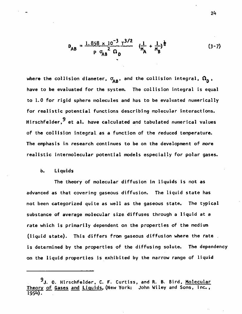
where the collision diameter, and the collision integral, O g ,
have to be evaluated for the system. The collision integral is equal
to 1.0 for rigid sphere molecules and has to be evaluated numerically
for realistic potential functions describing molecular interactions, q
Hirschfelder, et al. have calculated and tabulated numerical values
of the collision integral as a function of the reduced temperature.
The emphasis in research continues to be on the development of more
realistic intermolecular potential models especially for polar gases.
b. Liquids
The theory of molecular diffusion in liquids is not as
advanced as that covering gaseous diffusion. The liquid state has
not been categorized quite as well as the gaseous state. The typical
substance of average molecular size diffuses through a liquid at a
rate which is primarily dependent on the properties of the medium
(liquid state). This differs from gaseous diffusion where the rate ,
is determined by the properties of the diffusing solute. The dependency
on the liquid properties is exhibited by the narrow range of liquid
^J. 0. Hirschfelder, C. F. Curtiss, and R. B. Bird, Molecular Theory of Gases and Liquids, (New York: John Wiley and Sons, Inc.,195*0 •
25
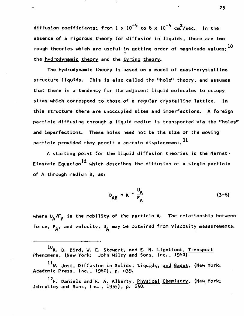
-5 -5 2diffusion coefficients; from I x 10 to 8 x 10 cm. /sec. In the
absence of a rigorous theory for diffusion in liquids, there are two
rough theories which are useful in getting order of magnitude valu e s : ^
the hydrodynamic theory and the Eyring theory.
The hydrodynamic theory is based on a model of quasi-crystalline
structure liquids. This is also called the ltholetl theory, and assumes
that there is a tendency for the adjacent liquid molecules to occupy
sites which correspond to those of a regular crystalline lattice. In
this structure there are unoccupied sites and imperfections. A foreign
particle diffusing through a liquid medium is transported via the "holes"
and imperfections. These holes need not be the size of the moving
particle provided they permit a certain displacement.^
A starting point for the liquid diffusion theories is the Nernst- 12Einstein Equation which describes the diffusion of a single particle
of A through medium B, as:
da b ■ K T £ (3'8>A
where U./F is the mobility of the particle A. The relationship betweenn nforce, F . , and velocity, U. may be obtained from viscosity measurements.n n
*^R. B. Bird, W. E. Stewart, and E. N. Lightfoot, Transport Phenomena, (New York: John Wiley and Sons, Inc. , I960).
“ w. Jost, P if fusion in Sol ids, Liquids, and Gases. (New York: Academic Press, Inc. , I960), p. 439-
12F. Daniels and R. A. Alberty, Physical Chemistry, (New York:John Wiley and Sons, Inc., 1955), p- 650.

26
After assuming a limiting case of, no tendency for the fluid to stick13to the diffusing particle; it can be shown that the diffusion coef
ficient can be approximated by
% ft > X ( J v * (3.9)k T 2if vV.;A
The Eyring rate theory attempts to explain the transport phenomena
on the basis of a simple model for the liquid state. The theory gives
a relationship very similar to Equation (3~9), but it does not fit the
data as well.14One of the best empirical relations is the one by Wilke, based
on the Stokes-Einstein equation. The correlation can be expressed by
the following analytical expression;
-a V * T °ab '■ -o.6~ <3-10>
H A
where fx = the viscosity of the solution
0^ 3 the association parameter based on the solvent, B.
This relationship applies only for dilute solutions of non-dissociating
solutes; and is good within ±1 0 per cent.
13R. B. Bird, W. E. Stewart, and E. N. Lightfoot, Transport Phenomena, (New York: John Wiley and S o n s I n c . , I960) , p. 514.
litC. R. Wilke, "Estimation of Liquid Diffusion Coefficients," Chemical Enqineerinq Progress, XLV (1949), pp* 218-224.

27
3. Eddy Diffusion
Substances can be transferred within a phase by the motion of
finite parcels of fluid. This process is much more rapid than molecular
diffusion and it is in the preferred mode of operation of industrial
processes, just as it is in the case of heat transfer. The dispersion
generated by turbulence in the fluid is usually measured experimentally
and correlated with a few important parameters. Since turbulence has
not been completely described mathematically, the eddy diffusion
coefficient cannot be predicted from theory. However using an
analog of Fick's Law, a parameter called the eddy diffusivity can
be evaluated experimentally.
jt = ' °AB dV dx (3~U)The coefficient is useful if a numerical value of eddy diffusivity
is known for the flow regime in question. In chemical engineering
technology this is not often evaluated separately but is usually
"lumped" in another quantity called the mass transfer coefficient.
4
4. Interphase Mass Transport
Continuous contacting processes such as absorption, distillation,
extraction, drying, and heterogeneous chemical reactions require
engineering analysis of complex mass transfer mechanisms. Because
of the complexity of the mechanism, the use of empirical correlations
to predict the parameters of simple mathematical models have been in
use. The achievements of chemical engineering technology attest to

28
the usefulness of these tools. It is the goal of engineers however
to strive for more realistic and definitive mathematical expressions
for the description of the rate processes.
a. Two Film Theory
W h i t m a n , a n d Lewis and Whitman^ proposed the use of
diffusion coefficients per unit area for the description of inter
phase mass transfer. In 1923 there was some uncertainty over the use
of a proper driving force to express mass transfer rates. The authors
proposed that, in turbulent flow of liquid and gaseous phase, there
was a stagnant layer of each phase on either side of the interface.
The rate of transfer through these layers were slow and occurred by
molecular diffusion. The name given this theory was the two-film
theory, although no sharp demarcation lines for the film boundaries
were inferred. It was proposed that these coefficients be evaluated
experimentally. The relationships which were proposed are:
aH? " *G <PG * P i> ' kL ' Ci * CL> (3 " ‘ 2)
More recent presentations in some textbooks^ indicate that k° and k^
can be defined as follows:
1V G. Whitman, "The Two Film Theory of Gas Absorption," Chemical and Metallurgical Engineering, XXIX (1923) , p* 1**6.
16W. K. Lewis and W. G. Whitman, "Principles of Gas Absorption,"Industrial and Eng ineering Chemistry, XVI (I92*t) , p. 1215.
^T. K. Sherwood and R. L. Pigford, Absorption and Extraction,(2nd Edition; New York: McGraw-Hill, Inc., 1952), pp. 317~339-

29
0 P vRT x P,
(3-13)
(3-1*0
Because of the impossibility of measuring x, or because it does not 18
exist, the mass transfer coefficients are correlated with physical
parameters of the system. Possibly the concept of correlating x
arose as the theoretical relationships for predicting the diffusion
coefficients became available.
The concept of two films has been quite useful particularly in
the form of overall coefficients where the driving force could be
expressed as two easily measurable bulk phase concentrations.
N/A - Kg (pG - p*) (3-15)
N/A = Ku (c* - cL) (3-16)
«jjfwhere p and c are the partial pressures of the solute in equilibrium
with a liquid having a bulk concentration of c^, and the concentration
of solution in equilibrium with the bulk solute partial pressure of
Pg. Where the gas-liquid system can be described with a linear
18L. Lapidus, Fundamentals of Mass Transfer Processes, Part 1, Separation Processes. ed. R. F. Chapman (New York; Rheinhold Publ.Co., 1961), p. 2.

30
equilibrium relationship called Henry's Law, p 3 me, then the two
individual mass transfer coefficients can be combined to evaluate
the overall coefficients,
1 - 1 ♦ (3-17)Kg k . ,oG kL
and,
k " = d r + ^ (3_18)kL G k£
b. Penetration Theory
Because of the difficiencies of the two film theory, it was
only natural to inquire into liquid phase diffusion with the possibility
of constructing a more realistic model for the mass transfer process.19 20Such a model has been proposed by Higbie, Danckwerts, and Toor and
21Marchello and is termed the penetration theory.
In a qualitative description, a liquid which flows down a piece
of packing has turbulent eddies extending to the surface. Each eddy
brings a fresh parcel of fluid to the surface from the bulk fluid.
19R. Higbie, "The Rate of Absorption of a Pure Gas into a Still Liquid during Short Periods of Exposure',*1 A. I. Ch. E. Journal, XXXI (1935), p. 365.
20P. V. Danckwerts, "Significance of Liquid Film Coefficients in Gas Absorption." Industrial and Engineering Chemistry, XL)I I (1951), p. 1460.
21H. L. Toor and J. M. Marchello, "Film-Penetration Model for Mass and Heat Transfer," A. I.Ch. E. Journal. IV (1958), p. 97-

31
With the assumption of no interfacial resistance, one considers the
liquid parcel surface saturated with solute gas. Absorption occurs
by molecular diffusion, corresponding to the unsteady state equation
presented as Fick's Second Law (Equation (3“3)). The rate of absorption
decreases with time until the element of fluid is replaced with another
fresh element from the fluid bulk. The overall effect is a continuous
replacement of old surface masses with fresh elements. At any one
time the entire liquid surface is made up of a series of surfaces
with different ages or contact times with the gas phase; the surface
is now an unsteady state heterogeneous medium instead of a steady-22state homogeneous phase as characterized by the film theory. The
real problem associated with this approach is how to characterize the23surface age. Higbie proposed that it is the time required for liquid
2kto flow over a packing piece. Danckwerts proposed a time distribution
which must be evaluated experimentally and correlated with the flow and
packing characteristics of a column.
Fick's Second Law, which is Equation (3“3) above, represents un
steady state one dimensional molecular diffusion into a semi-infinite
med i urn.
DA (3-19)
Lapidus, op. cit.
^Higbie, op. cit. , p. 365. 2kDanckwerts, op. cit.
32
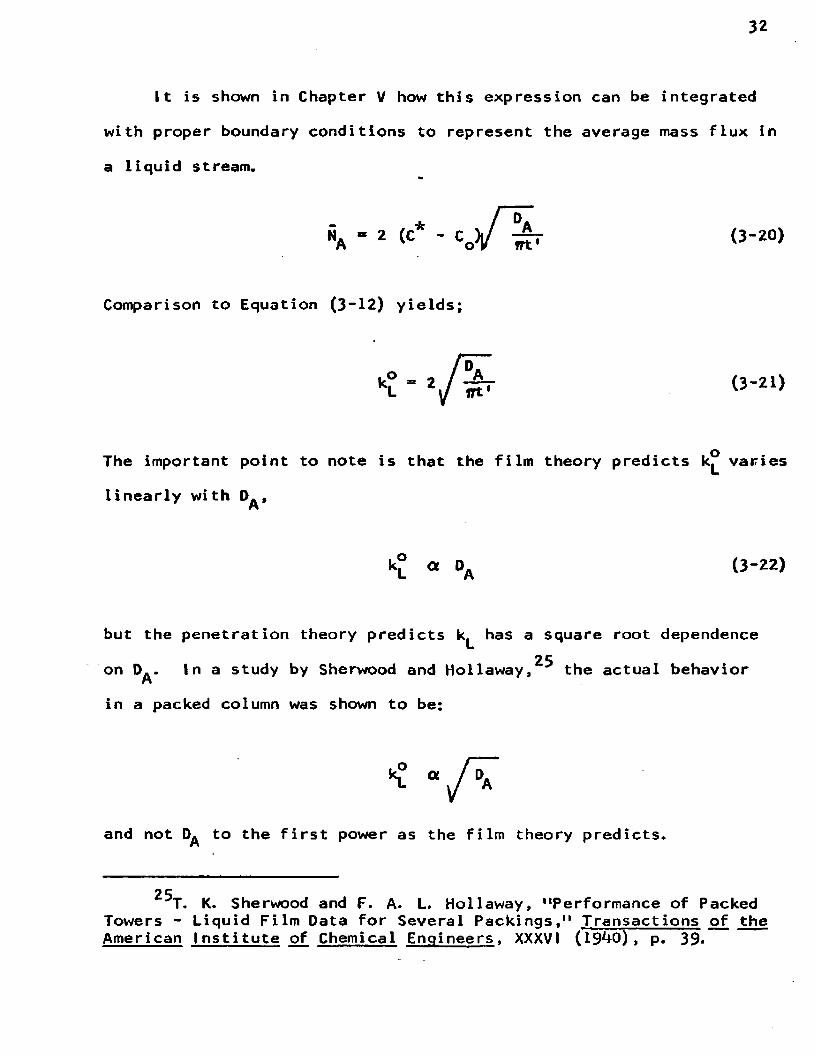
It is shown in Chapter V how this expression can be integrated
with proper boundary conditions to represent the average mass flux in
a liquid stream.
Z5-NA = 2 (C* - CQ)l/ “ T (3-20)
Comparison to Equation (3- 12) yields;
(3-21)
The important point to note is that the film theory predicts k° varies
linearly with D^,
(3-22)
but the penetration theory predicts has a square root dependence25on D^. In a study by Sherwood and Hollaway, the actual behavior
in a packed column was shown to be;
and not to the first power as the film theory predicts.
25T. K. Sherwood and F. A. L. Hollaway, "Performance of Packed Towers - Liquid Film Data for Several Packings," Transactions of the American I nsti tute of Chemical Engineers, XXXVI (19*+0) , p. 39.

33
5. 1nterfacial Mass Transfer Accompanied by Chemica1 Reaction
This study considers the transient transfer of a gaseous solute,
CO2' SO^, or CH^SH to an aqueous phase. The methyl mercaptan transfer
was studied with various concentrations of sodium hydroxide solutions.
The sodium hydroxide is practically completely ionized into Na and
OH ions in the aqueous phase which are not released (or soluble) in
the gaseous phase. The mass transfer process of CH^SH is accompanied
by an irreversible chemical reaction between the transferring specie
and the anion, OH .
CH3SHU ) ♦ OH'4 - CHjS^j + H20 (i) (3-23)
The reaction is usually written to show the formation of a mercaptide
salt, which is also completely ionized in the aqueous phase. Equation
(3-23) indicates the mechanism in which we are interested. The product
of the chemical reaction CH^S is also considered non-volatile to the
gas phase. A schematic drawing in Figure 2 depicts the process indi
cating the concentration gradients of reactants and products.
The chemical reaction, which was postulated, is assumed to
proceed according to the second order kinetic equation:
(moles of CH~SH reacting)------ (t j,ne) (volUme) " V tCHjSHHOH-] (3-21.)
The reactants, [CH^SH] and [OH 1 must diffuse toward each other, collide,
and exchange a proton, at the rate indicated by k_, and the products

34
Reaction Zone
GAS
interface
CH3 SH + [OH-] C H .S - +
[N a+]
[o h - ]
Figure 2 , Concentration in Double Film During Absorption of Methyl Mercaptan by Aqueous Sodium Hydroxide.
35
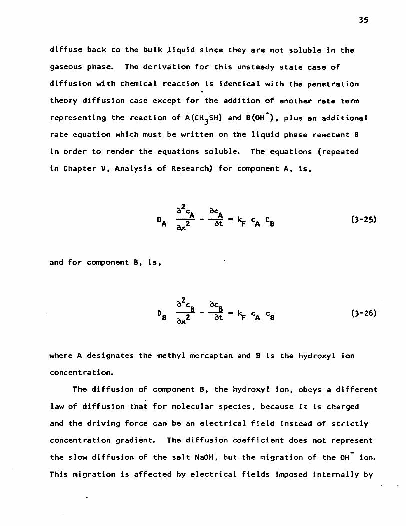
diffuse back to the bulk .liquid since they are not soluble in the
gaseous phase. The derivation for this unsteady state case of
diffusion with chemical reaction is identical with the penetration
theory diffusion case except for the addition of another rate term
representing the reaction of A(CHjSH) and B(OH ), plus an additional
rate equation which must be written on the liquid phase reactant B
in order to render the equations soluble. The equations (repeated
in Chapter V, Analysis of Research) for component A, is.
be_Adt *¥ CA CB (3-25)
and for component B, is,
d^c dcDB ^ 2 dt = 'V CA CB (3-26)
where A designates the methyl mereaptan and B is the hydroxyl ion
concentration.
The diffusion of component B, the hydroxyl ion, obeys a different
law of diffusion that for molecular species, because it is charged
and the driving force can be an electrical field instead of strictly
concentration gradient. The diffusion coefficient does not represent
the slow diffusion of the salt NaOH, but the migration of the OH ion.
This migration is affected by electrical fields imposed internally by

36
the counter diffusing CH^S , which moves with a different velocity than
the OH ion. This will produce a small local deviation from electrical
neutrality and result in the establishment of a temporary electric
field. The Nernst-Planck Equation2**,27*28,29 describes the diffusion
of ions in dilute solutions,
N . - - D i + E z i D . 1,1 <3-27)
The second term on the right hand side represents the motion of the
ionic species under the influence of an electric field. Several
a u thors^*^**32.33 ^ave used this equation and approached the problem34of solving for an effective diffusion coefficient. Brian showed
2^W. Nernst, Zeit, Phys. Chem. , (Leipzig) II (1888), p. 613.
27lbid.. 4, 129, (1889).
2®M. Planck, Ann. Physik, XXXIX (1890), p. 161.
291bid. . 40, 561, (1890).^ J . R. Vinograd and J. W. McBain, "Diffusion of Electrolytes
and of the Ions in Their Mixtures," Journal of the American Chemical Society. LXIII (1941), p. 2008.
^*T. K. Sherwood and J. C. Wei, "Ion Diffusion in Mass Transfer Between Phases," A. I. Ch. E. Journal. I (1955), p. 522.
32T. K. Sherwood and J. M. Ryan, "Mass Transfer to a Turbulent Fluid With and Without Chemical Reaction," Chemical Engineering Science. XI (1959), p. 81.
33P. L. T. Brian, R. F. Baddour, and D. C. -Matiatos, "An Ionic Penetration Theory for Mass Transfer with Chemical Reaction," A.I.Ch.E. Journal. X (1964), p. 727.
bid. , Equation 18, p. 731.
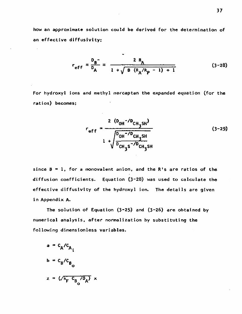
how an approximate solution could be derived for the determination of
an effective diffusivity:
2 RAreff ~ D'A 1 + y B (RA /Rp - 1) + 1
(3-28)
For hydroxyl ions and methyl mercaptan the expanded equation (for the
since B = 1, for a monovalent anion, and the R's are ratios of the
diffusion coefficients. Equation (3~28) was used to calculate the
effective diffusivity of the hydroxyl ion. The details are given
in Appendix A.
The solution of Equation (3“25) and (3~26) are obtained by
numerical analysis, after normalization by substituting the
following dimensionless variables.
ratios) becomes:
(3-29)
38
8 = kp B0 t
The normalized equations are:
(3-29)
(3-30)
at a specific r and q, the equations are solved for a and b as a function
of 6 and Z. The parameter r is evaluated with Equation (3"28), and q
is the ratio of the hydroxyl ion at the beginning of the exposure, and
the equilibrium concentration of methyl mercaptan at the interface.
The details of the solution are given in Chapter V. Once a and b are
determined as a function of 9 and z the effect of chemical reaction on
the mass transfer can be determined. An enhancement factor $ has been
defined which relates the absorption coefficient with reaction to the
absorption in the absence of reaction, i.e. physical absorption.
Considering a material balance rate equation for consumption of a
and b by the reaction and ratioing this expression to the penetration
theory for physical absorption, an expression for evaluating $ can be
obtained. (The details of the derivation is in Chapter V).

* " ^ /0“ [a + q (1 - b)] dz
39
(3-29)
The normalized variable 8 (0 3 k: C. t) , which has the contact time,o
t, in its definition, is eliminated by substituting for it from the
penetration theory solution _
{ - ■ / £
_A
* ^
and
Substituting for t in Equation (3“31)> the result is
(3-21)
t = --- 1 2 (3-30)
6 = kp cB t (3-31)
'V CB DA9 3 CB 1 ■ i [ .02 ] a w M (3'32)O
Equation (3-29) becomes,

40
^ " 4/M J'o” [ a + q ^ " b)] dz
The more general variable M can be interpreted as a measure of how
rapid the chemical reaction is, relative to physical absorption in
an absorber with the physical absorption coefficient, k£. A typical
solution for second order irreversible reaction is depicted in Figure
3> At the asymptotic sections of high M, the reaction is so fast
the absorption process has no resistance in the liquid phase due to
chemical reaction.

mCM
o
ooCM
oo
o*•
oCM
CM
J o J
Figure 3 , Theoretical Solution for Penetration Theory Accompanied by Irreversible Second Order Chemical R eac tion .fa t te r Brian, et al,I9604

CHAPTER. IV
EXPERIMENTAL WORK
1. Laminar Liquid Jet
A versatile gas absorption device, called a laminar liquid jet,
was fabricated to study the diffusion coefficients, mass transfer
coefficients, and the kinetics of absorption with chemical reaction.
Himmelblau^ reports that the device is suitable for measuring diffusion
coefficients with an accuracy of ± 1%. Photographs and an engineering
drawing show the details of construction of the assembled apparatus.
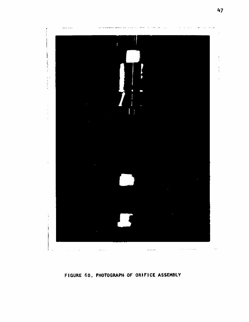
Figures 4, 5, 6A, and 6B. One of the important parts of the jet is
the orifice through which the absorption liquid discharges. Thin
sharp edged orifices produces the minimum amount of boundary layer
retardation. In order to assure a permanent diameter calibration by
the elimination of corrosion, the orifice was machined out of 0.003 in.
platinum sheet. A 0.0561 inch hole was drilled in the orifice plates
which were mounted in compression between brass blanks. A smooth
sharp edged hole resulted from the precision drilling. Figure 6A
and 6B.
The orifice was mounted at the end of a piece of precision Pyrex
glasstubing, ground flat at the end. The apparatus is equipped with
*D. M. Himmelblau, "Diffusion of Dissolved Gases in Liquids," Chemical Reviews. LXIV (1964), pp. 527-550.
42
43
a 2 inch diameter glass tubular absorption chamber, 14.75 inches long,
and jacketed with a concentric Plexiglas shell to provide an annulus
for circulating water. Figure 4. Care was taken in the machining of
the parts to assure precise perpendicularity and alignment of orifice
and receiver. Alignment screws were provided to adjust a floating
head supporting the orifice and tube; and to compensate for metallic
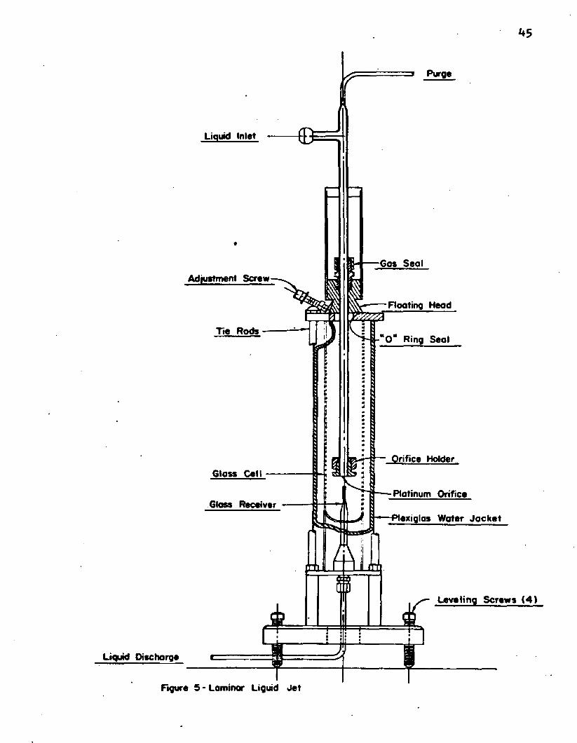
expansion and inaccuracies in the glass tube. The receiver was
fashioned by fusing a short piece of 1.85 mm. I. D. capillary glass
tube and having an internal diameter only slightly larger than the
liquid jet. Figure 5* This design minimized end effects by the elim
ination of entrained gas and allowed for precise level control in the
receiver with a fine needle valve, a 1/4“ , Whitey, 22S4. The liquid
in the receiver was controlled to within 0.05 mm. of the overflow
point at the top. The jet length was read at the top of controlled
liquid level.
The equipment in contact with the gas and absorbing liquid was
fabricated out of glass, Teflon, and stainless steel (316). The
floating head was sealed with a fluorocarbon elastomer ring (IE0ir-ring) under compression. The gas inlet and outlet ports were at opposite
ends of the cell designed to provide for positive gas flushing of the
absorption chamber.
The temperature of the cell and absorbant was controlled with a
thermoelectric, circulating constant temperature bath, marketed by
Scientific Apparatus, Inc. The circulating water was controlled
within ±0.01°C, and the room temperature controlled within ± 2°C
of 25°C. Figure 7*
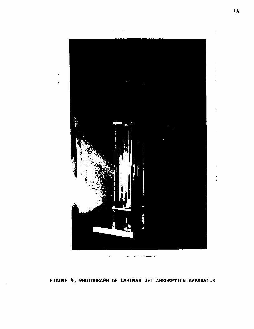
FIGURE *t, PHOTOGRAPH OF LAMINAR JET ABSORPTION APPARATUS
**5
Purge
Liquid Inlet
60s Seal
Rooting Head
Tie RodsO" Ring Seol
Orifice HolderGloss Cell
Platinum OrificeGloss Receiver
i *■— Plexiglas Water Ja c k e t
Leveling Screws (4 )
Liquid Discharge
Figure 5 - Laminar Liquid Je t
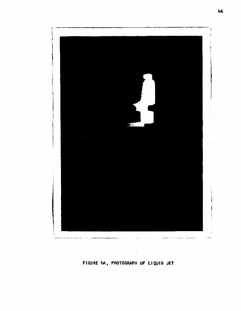
FIGURE 6A, PHOTOGRAPH OF LIQUID JET
I
M
FIGURE 6B, PHOTOGRAPH OF ORIFICE ASSEMBLY

Fume Hood
Water in
ConatontWotor ■ Jocket -
HoodLiquid SupplyBubbleSystemFilm
LaminarMeter Jet
Scrubbed
LiquidRotameter
GoaRotometer
ScrubbersWater In
GasSupply
Manometer
GasExcess
Soap v ^ Supply |Check
Figure 7 -Schematic Flow Diagram of Absorption Apparatus

**9
The level of the liquid feeding the rotameters was maintained
within ± 0.5% with an automatic syphon level controller. The liquid
to the orifice was metered with a calibrated Fisher and Porter Flowrator
rotameter, No. 3F-3/8-25“5» with a glass float, Type CO-38.The laminar jet was mounted on a table-type suspension system built
from ty1 x 1+" and 2" x 6" wooden members. The table was anchored to the
concrete floor independent of the laboratory bench top, where the venti
lation blowers and circulation pumps were mounted. This vibration-free
mounting of the absorption cell provided satisfactory jet stability
without any ripples as determined by microscopic examination.
The gas absorption rates into the liquid jet was metered with a
bubble film flowmeter. The bubble film flowneter was fabricated out
of a standard 50 ml. liquid burette by reshaping the inlet to allow
the introduction of a single soap film; and by building a bubble
breaker and liquid soap return line from the top outlet. The used
soap solution was recycled to the bubble meter inlet. A positive gas
purge under slight pressure was maintained at the inlet of the film
meter, by metering excess gas through a dip tube submerged 1/16 inch
below a water interface. This procedure, in conjunction with pressure
readings in the cell chamber assured an adequate gas supply at atmos
pheric pressure to the gas chamber. This technique was tested by
analyzing the liquid effluent during the SC>2 calibration runs. The
technique was found to be more precise and as accurate as the iodo-
metric titration analysis of sulfur dioxide in water. The rate of
absorption was measured by timing displacement of gas as indicated
by the rise of a soap bubble film in the gas burette.

50
2. Diameter Measurements
Review of the literature indicated that the thin plate orifice
would produce a jet of nearly constant diameter; with the maximum
diameter variation occurring in the first 0.1 cm. below the orifice.
The diameter of the laminar liquid jet was measured with a Gaertner
travelling microscope at three liquid flows, at two angles, and at
various points along the jet length. The diameter measurements at
right angles indicated the jet was circular within the accuracy of
the microscope which was ±0.1%. Diameter measurements indicated
that the jet was near ideal and could be represented by the Equation
(4-1) at approximately one centimeter below the orifice.
D IT2 g D J* y -1/4§- = ( i + -------V ~ > v*-1)Do 8 q'
where D ™ the initial diameter of the jet, cm. o 2g = gravitational acceleration, cm./sec.
q' = flow rate, cm?/sec.
y = jet length, cm. ,
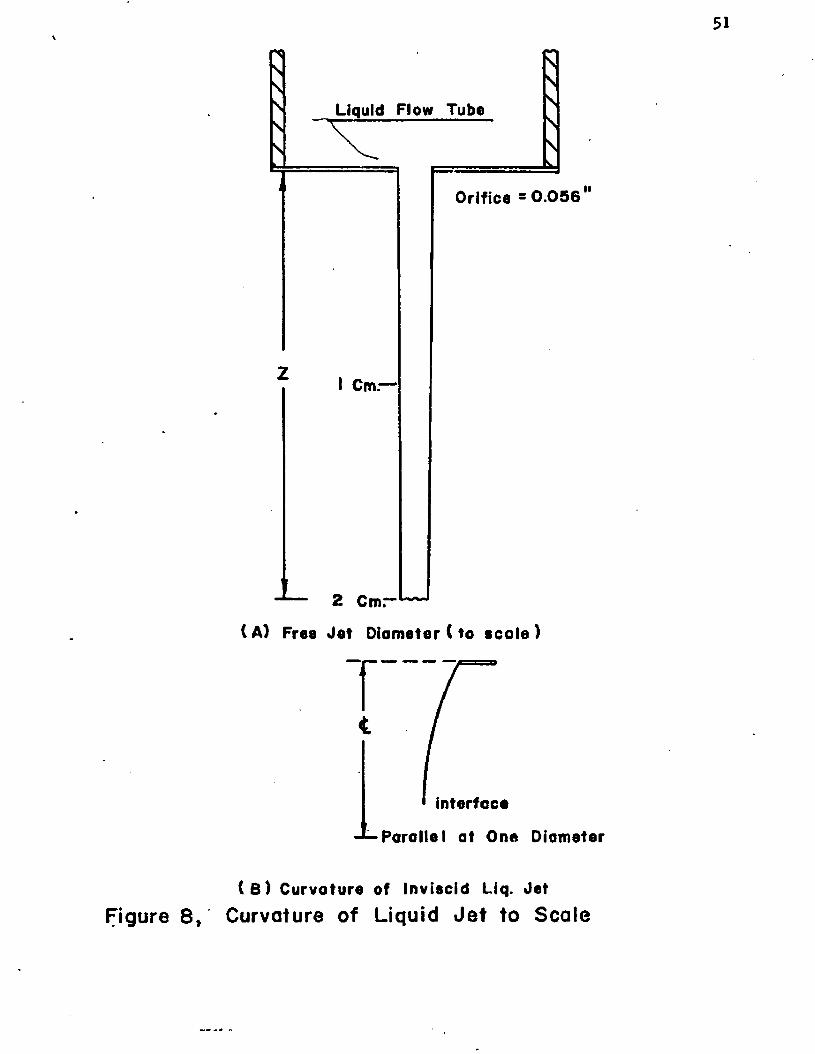
Figure 8 shows the curvature of the jet to scale. The contraction
of an inviscid jet is shown as a comparison. The diameter is very
nearly constant along most of the jet length and the use of a mean
diameter for a jet of certain length and flowrate is hereby justified.
2L. E. Scrivens and R. L. Pigford, "On Phase Equilibrium at the Gas-Liquid Interface During Absorption," A.I.Ch.E. Journal, IV (1958), p. 439-
sss
Liquid Flow Tube
Orifice = 0 .0 5 6
I Cm.—
2 Cm.*”
(A ) Free J e t Diameter ( to s c a le )
rinterface
-J-P a ra lle l a t One Diameter
( B ) C urvature of Inviscid Liq. Je tFigure 8 , Curvature of Liquid J e t to Scale

52
3* Test Materials
The compressed gases which were used in the studies are carbon
dioxide, sulfur dioxide, and methyl mercaptan. These gases were
obtained from the Matheson Company with the following certified
purity:
Carbon Dioxide 99*99%
Sulfur Dioxide 99*9 %
Methyl Mercaptan 99* 0 %
The water used in the absorption studies was distilled in a
Barnstead Still with a modification for condensation under a positive
steam purge. As a precautionary measure the warm water was subjected
to low vacuum while it cooled, to remove any dissolved gases which
might have been absorbed during distillation.
Sodium hydroxide, used in making up absorbing solutions, was a
technical grade. The concentration of the solutions was determined
by volumetric analysis using HCl as the titrant.
h. Calibration Procedures
The laminar liquid jet was first tested on the absorption of SO2 in water as one of the first steps in the calibration of the equipment.
Thermal stability was established in the absorption apparatus, after
about one hour of circulating the tempered water. The gas absorption
chamber was flushed for 15 minutes with 100 cc. /minute of sulfur dioxide. The liquid jet was started initially with no liquid level
in the receiver. All air bubbles had previously been purged from

53
the receiver and liquid system. With the gas continuously flushing
the absorption cell, the soap film gas meter was readied by allowing
a few bubbles to pass through the gas burette. With a liquid flow
rate set and the jet centered over the receiver, the level in the
receiver was brought up gradually by closing the needle valve slowly,
being careful not to spill any liquid over the chamber. The gas
chamber was sealed by closing off the purge outlet; and the gas flow
was lowered while maintaining a slight positive purge past the meter
inlet. As' the gas was absorbed by the liquid, the volumetric uptake
of the gas was timed by noting the rate of movement of the bubble
film in the gas burette. Additional soap films could be placed in
the gas burette without interrupting the gas flow, as the older
films broke or passed into the soap recycle chamber. The length
of the jet from the orifice to the receiver was measured with a
Gaertner cathetometer (a vertically travelling microscope) which
will detect distances within ± .05 mm.The contact time was varied by changing the liquid flow rate
and jet length. The jet length could be changed by shutting off the
apparatus, releasing the compression fitting on the receiver, moving
the receiver vertically, and then tightening the compression fitting.
The procedure for starting up was followed again to get a series of
observations at this new jet length.
The gas burette was calibrated by collecting samples of liquid
effluent and titrating for S02* The liquid- flowed through an auto
matic 10 ml. pipette and discharged to a flask containing a known
equivalent weight of iodine. The iodine was back titrated with
sodium thiosulfate as in standard iodometric titration procedures.

54
All excess gas from flushing and purging sequences had to be
collected, scrubbed, and vented outside. Sulfur dioxide and later
methyl mercaptan made the use of a strong oxidant (KMnO^) in the gas
scrubbers imperative. Positive venting lines were connected to the
cell flushing outlet, the gas burette purge, and the liquid receiver
vessel. The gas was drawn through a series of three KMnO^ gas washing
bottles and pumped to an external building vent with a high volume
carbon vane vacuum pump.
The entire technique and apparatus were tested by obtaining
measurements on the system CO^ “ at 25°C. This system has been
thoroughly studied and accurate data on the diffusion coefficient of
carbon dioxide is available. The experimental procedure was similar
to the one described above for sulfur dioxide, with the exception of
the liquid analysis. The absorption of the CO2 in water was so low
at the normal contact times; that normal titrimetric procedures were
too insensitive. The water used in this study remained sealed from
the atmosphere throughout the absorption runs to prevent absorption
of ambient The calibration showed the technique and the apparatus
fundamentally sound. The results are discussed in Chapters V and VI.
5. Experimental Procedures
The experimental procedures for absorption with chemical reaction
are similar to the one used on calibration studies. The aqueous solutions
of sodium hydroxide were mixed and allowed to stand for an hour or more.
Multiple samples of solution were withdrawn from the vessel and titrated
for NaOH. The solutions were subjected to a vacuum of 29 in. Hg. for
another hour to remove traces of dissolved gases which might have
interferred with the absorption study. Tempered water was circulated
through absorption cell and solution heat exchanger until thermal
stability was reached. The gas burette and cell were flushed with
pure gas for 15 minutes. The jet was adjusted to a predetermined
length and the liquid flow to the orifice adjusted. When all conditior
were satisfactory the chamber was sealed and the gas absorption rate
timed on the bubble film flow meter. Several determinations were made
at a liquid flow rate and jet length until the precision was satis
factory. The liquid flow rate was changed holding the jet length
constant and additional determinations made at this point. The
apparatus was shut off, the jet length changed, the cell purged,
and the start up procedure repeated over again. Temperature, baro
metric pressure, cell pressure, liquid rotameter reading, jet length,
and the determination of absorption rate were the raw data recorded.
A change in liquid concentration required an extensive flushing
of all, liquid lines, orifice, and receiver. The restart procedure as
described above was followed for each jet length at a sodium hydroxide
concentration. •

CHAPTER V
ANALYSIS OF RESEARCH
The analysis of the data involves the use of a fluid mechanic
model, solutions to the penetration theory, and a packed absorber
model which are too specialized to include in Chapter III, The Theory,
but important enough to be included in a separate chapter apart from
the Appendix. The following sections describe the details of the
analysis of research.
1. Fluid Mechanics
One of the conditions on which the penetration theory is based
on the non-turbulent condition of the liquid into which the solute
diffuses. This condition rules out bulk mixing and eddy diffusion.
The laminar jet used a commonly observed phenomenon; that is, a liquid
stream in free fall accelerates with negligible momentum interchange
across the interface with the gas phase. In free fall each fluid
particle is affected to the same degree by gravitational force. Since
the system is isolated, there is no mixing due to momentum exchange
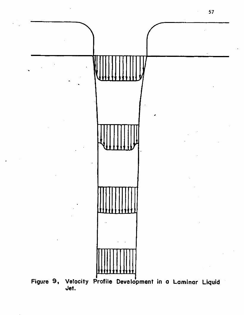
and the velocity profile is flat. Figure 9 shows how the velocity
profile develops. For a jet discharged from a thin orifice the
boundary layer retardation caused by contact with the orifice walls
56
57
Figure 9 i Velocity Profile Development in a Laminar Liquid Jet.
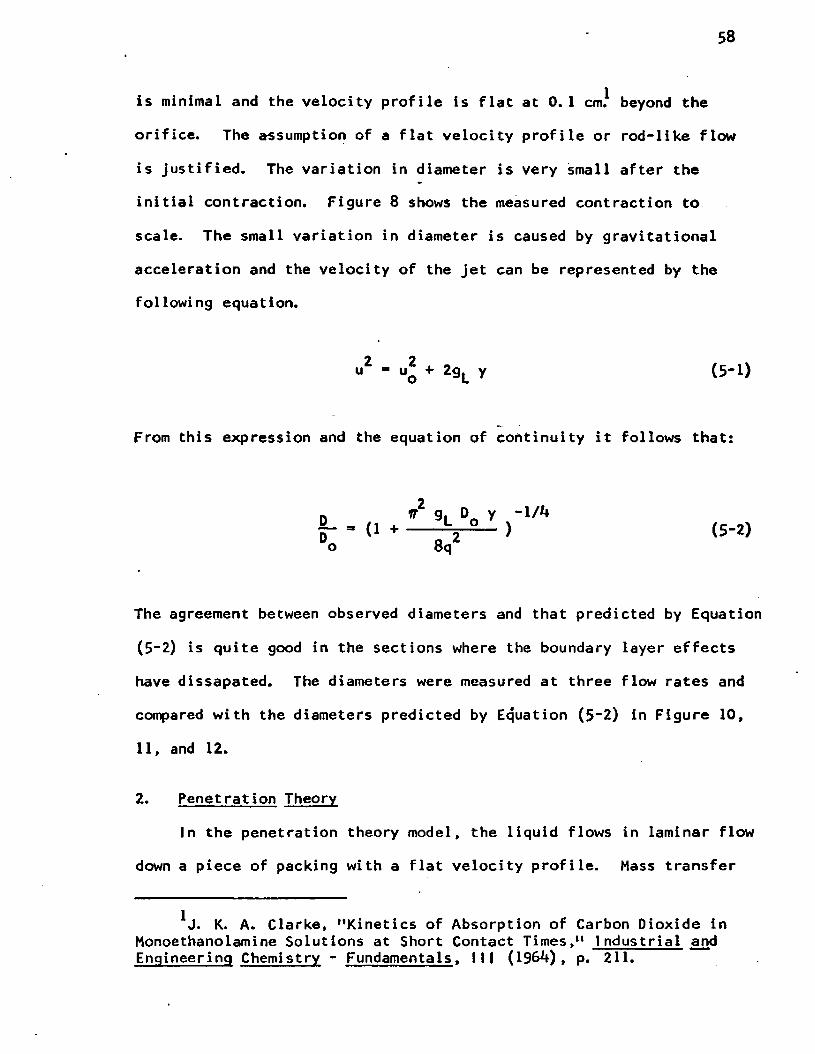
is minimal and the velocity profile is flat at 0. 1 cm.* beyond the orifice. The assumption of a flat velocity profile or rod-like flow
is justified. The variation in diameter is very small after the
initial contraction. Figure 8 shows the measured contraction to scale. The small variation in diameter is caused by gravitational
acceleration and the velocity of the jet can be represented by the
following equation.
u2 - u2 + 2gu y (5-1)
From this expression and the equation of continuity it follows that:
D ff2 9L Do y _1//t- (1 + ---- S V 2-- ) (5-2)Do 8q
The agreement between observed diameters and that predicted by Equation
(5“2) is quite good in the sections where the boundary layer effects
have dissapated. The diameters were measured at three flow rates and
compared with the diameters predicted by Equation (5~2) in Figure 10,
11, and 12.
2. Penetration Theory
In the penetration theory model, the liquid flows in laminar flow
down a piece of packing with a flat velocity profile. Mass transfer
J. K. A. Clarke, "Kinetics of Absorption of Carbon Dioxide in Monoethanolamine Solutions at Short Contact Times,“ Industrial and Engineering Chemistry - Fundamentals. i11 (196*0 , p. 211.

Dia
met
er,(
mm
.)
59
1.20
1.15
MO
1.05
1.00
--------- 1---------- 1------- “ 1-----------1----------1--------_i----------- ,-----------
Flow 2 .3 5 cc ./sec .Do 0 .1 1 8 cm.
nr p / /o / /
• '
“ Predicted by Equation 5-2 using D. 5--------------
i i - j _______ i_______I_____ i i1 . 2 3 4 5 6 7 8
Length of Jet (cm .)Figure 10, Diameter of Laminar Liquid Jet

Dia
met
er,
(mm
.)
60
1.20
1.15
1.10
1.05
1.00
--------- 1----------1---------- r - i t ----------r “ i
Flow 3 .6 0 c c ./$ e c .D0 0.117 cm.
- —
---------------------------" Predicted by o ------ — ‘ -----------a ________“
Equation 5^2 using D#
—
— -
** ------- 1----- — •—_____ 1_____ _J_______1_______1----------I 2 3 4 5 6 7 B
Length of Jet (cm.)F igured , Diameter of Laminar Liquid Jet

Dia
met
er,(
mm
.)
61
Flow 4 .1 5 cc ./sec . D« 0.115 cm.
1.20 —
1.15—0 ----------- o
I.10-
1.0!
1.0 0 -
Predic ted byEquation 5 -2 using Do
--------------
J_______ I_______ I_______ I________L1 2 3 4 5 6 7 8Length of Jet (cm.)
Figure 12, Diameter of Laminar Liquid Je t

62
takes place by molecular diffusion for a certain contact time. The
contact times are so short that the gas does not penetrate deeply into
the liquid, and the liquid depth is assumed infinite. For the case of
diffusion into a cylinder of fluid, the liquid penetration depth is
also too shallow to be affected by the curvature of the cylinder.
When the conditions cited in Chapter III are met, Fick's Second Law
can be solved for the unsteady state case to express the mass transfer
to a slug of liquid during a short exposure. Figure 13 shows the
coordinates of a system in the derivation of Fick's Law. A control
element fix, of unit width, is chosen; bounded by the coordinate x, and
x + fix. Diffusion into the element is a function of the linear concen
tration gradient, dC/dx, which is in essence Fick's First Law. Following
the laws of conservation of mass, the mathematical expression for rate
of transfer of A can be written:
Input - Output ■ Accumulation
da S - [da & + X (“a & » * ] - * ! ‘‘a 5*’ (5-3)
That is, the rate of mass transfer of A input. minus the rate of mass
transfer of A output. is equal to the accumulation of A in the control
element. The rate of mass transfer out is equal to the rate in plus
the rate of change of the flux over the element fix. Taking the
diffusion coefficient as constant, which it is for the case of low
concentrations, the equation becomes:

63
InterfaceAccumulation
3 CA 9 _ 9 C * „ %H
Concentration Prof I la at tlmatt
X + SX
Figure 13, One Dimensional Coordinates for the Derivation F ick 's Second Law Leading to the Penetration Theory Solution.

64
5dt (5 -4 )
The equation can be solved analytically for the particular set of
boundary conditions which are maintained with the laminar jet. These
boundary conditions are:
1) t » 0
2) x - 0
3) x ■= 00
2Using a technique called “ the method of combination of variables'1 the
partial differential equation is solved as follows: A solution is
anticipated of the form C./C. - x (ft) > in which 17 is a dimensionlessft ft̂variable x//4D^t. In terms of the new variables,
and
3 *CA /CA q} dt at art at (5-5)
d <VCA >_________o_az
rt
2R. B. Bird, W. E. Stewart, and E. N. Lightfoot, Transport Phenomena (New York: John Wiley and Sons, Inc. , i960).
65
where
* > ■ 4*n
Equation (5~*+) becomes:
tf* + 2 n x' - 0 (5-7)
Boundary Condition 1. at T) » 0, \ ~ 1
Boundary Condition 2. TJ ■ x “ 0
If X 1 is replaced by Y, the equation becomes a first order separable
differential,
Y ‘ + 2 tf Y - 0 (5-8)
and
_„2» S X' -Cj (5-9)
X - C1 C <l») + c , (5-10)
Application of the boundary conditions then gives;

The ratio of the integrals is called the error function, abbreviated
erf 77; evaluated numerically and tabulated in handbooks. The solution
of the unsteady state differential equation may be written,
where
V cao " 1 - 75 4” e‘”2 "»
- 1 - ? | erf rf
CA “ the concentration at any time in the liquid.
C. * the concentration of initial conditions,o
XTJ *= a dimensionless position variable.
t «* the time of contact.
Da ■ the diffusion coefficient.A
(5-12)
(5- 12a)
^K. A. Korn and T. M. Korn, Mathematical Handbook for Scientist and Engineers, (New York: McGraw-Hill, Inc., 1961), p. 899.

67
The local mass flux at a point on the interface x “ 0, at a position
y down the liquid jet, is;
(5“ 3)
The local flux is integrated over the entire length of the surface to
give the working equation: .
na t o t a l - ; o ye - \ s j - f So J (5-14)
The average rate is found by dividing the total quantity by the time of
exposure during which this total transfer occurred.
The equation represents the average mass flux transferred to the liquid
jet for a contact time t1. When experimentally measured data of N.A , avg.is plotted on the basis of, N. versus the reciprocal of the squareA , avg*root of contact time; the result should be a straight line, if the
experiment is a good test of the penetration theory. The slope of

68
the line is equal to 2 (C^ ). Knowing the solubility, , the
diffusion coefficient can be computed. As mentioned previously, the
laminar jet can be used to measure the diffusion coefficients with
very good accuracy.
3. Penetration Theory with Chemical Reaction
The problem of gas absorption accompanied with chemical reaction
can be treated by adding an extra "output" term to the unsteady state
mass transfer Equation (5-3)* Considering the complete system, mass
transfer of A occurs across the gas-liquid interface as depicted
below:
The rate of the chemical reaction depicted by Equation (5“17) is assumed
to proceed according to the following equation:
a(g) (5-16)
where it reacts irreversibly with species B as follows,
A (L) + v -* Products (5-17)
R = kp [CA ]" [CB]m (5-18)
The parameters k p , n, and m are assumed constant. For a second
order reaction, this rate is represented by Equation (5-18), as,

using this as the other “output11 term in the unsteady state mass transfer. The general expression is as follows:
d2CA- ^ a 'b
There are two dependent variables C^, and
independent expression for the rate of transfer o
before any solution is possible.
a2cR 3Cr°B - -sr - V CA CB
(5-20)
, and therefore another
f B must be derived
(5-21)
Both Equations (5-20) and (5~21) can be normalized by letting;

70
The resulting transformed equations are,
- H - ab (5-12)
r<< y ' * n * al> (5"23>
IfThe boundary conditions for the normalized equations are;
At 0 - 0, any z > 0 a 53 0
b - 1
At z = 0, any 0 > 0 a =* 1
At z any 0 a =* 0
b = 1
The boundary conditions are satisfied by the laminar jet according to
the previous discussion. The condition that a = 0 at the beginning of4a contact time requires that the chemical equilibrium is prevailing5and ■ 0 throughout the liquid. Peaceman has shown that gas**liquid
holdup is sufficient and the assumption is a good one in practical cases.
P. L. T. Brian, “Gas Absorption Accompanied by an Irreversible Reaction of General Order,'1 A. I. Ch. E. Journal. X (1964), p. 5*
^D. W . Peaceman, "Liquid Side Resistance in Gas Absorption With and Without Chemical Reaction,,r (Sc.D. Thesis, Massachusetts Institute of Technology, 1951).

71
The desired result from the solution of Equations (5“22) and (5“23)
is the ratio of to k£, (the ratio of the coefficient of absorption
with chemical reaction over the coefficient of absorption without
chemical reaction). Thus, $ is a measure of the amount by which
simultaneous chemical reaction increases the rate of absorption of
species A. Solving the differential equations for a and b as functions
of z and 0, $ can be obtained as follows using dimensional notation in
the derivation. At any time the total amount of species A in the liquid
per unit cross sectional area is;
J„ CA dx (5-^)
and of B,
00
Jo CB dx <5-25)
The amount of A consumed by the reaction of A and B is;
Jo <CB ■ CB> dx (5'26)o
The total amount of A, which has transferred into the liquid, is obtained
by summing the amount present at any time, Equation (S~2.k) , with the
amount consumed by reaction with B, Equation (5”26). The average rate
of absorption for a contact time t 1, is obtained by dividing the sum
described above by the contact time, t1.

72
00•To CA d* + So (CB - CB) dx Na -------------- JT----°---------- (5-27)
for physical absorption the average rate shown in Equation (5“ 15)» is;
(5-15)
and the coefficient of absorption is
" L - t J - 2 / ¥ <5- I5a)
The variable $ is equal to;
<fr = kL/k£ (5-28)
Substituting in Equation (5”28) for the coefficients the result is:
CD QO
f C.dx + f (CB - C_) dx J o A - J o ' B B' 2_ <5-29)
(f)(2)s] w
The equation is normalized by letting,
and the result is;
jQ [a + q (1 - b) 3 dz (5"30)
This equation is used to get $when values of a and b are obtained as
a function of z and 0. The solution of Equations (5“22) and (5“23)
is numerical unless two limiting cases are considered; 1) very fast
reactions, where $ is an asymptotic value of very large 0, and, 2)
pseudo first order reactions, which removes the non-linearity of
Equation (5“22), and allows an analytical solution.
The numerical solution by Brian,^ et al. was based on the equation
of Crank and Nicholson, for time centered, implicit finite differences.
The method of solution and the FORTRAN computer program for an I.B.M.
70^ computer appears in reference^. This program was adapted for this
^Brian, Hurley, and Hasseltine, op. cit.7E. H. Hasseltine and J. F. Hurley, “Solutions of the Penetration
Theory for Simultaneous Gas Absorption and Liquid-Phase Chemical Reaction, (S.B. Thesis, Massachusetts Institute of Technology, 1951)*
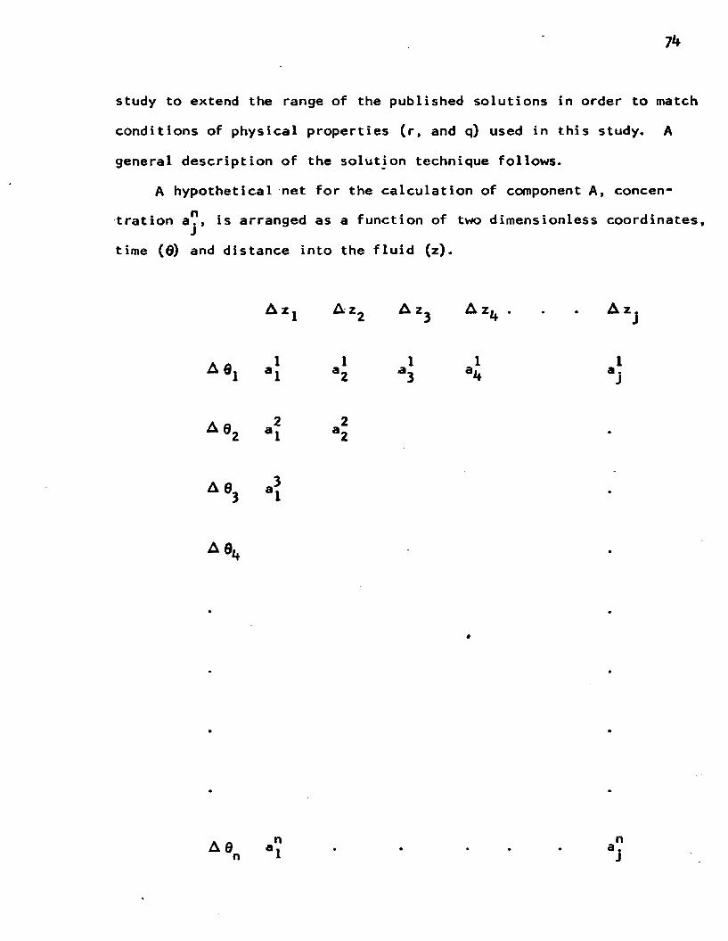
71*
study to extend the range of the published solutions in order to match
conditions of physical properties (r, and q) used in this study. A
general description of the solution technique follows.
A hypothetical net for the calculation of component A, concen
tration a?, is arranged as a function of two dimensionless coordinates,
time (6) end distance into the fluid (z).
A z j A z 2 A Zj A z^ A z
a ei ii a .J
Ae,
A 9j *|
A 0.
Art nA 0 a. n l

75
In the implicit method, the surrounding points are used to calculate,
the point under study. The forward point values are not all known,
so this results in a set of equations which have to be solved simul
taneously.
From the following general points, a set of finite difference
equations are developed.
o n a . ..J"1k
eA 9 12
A 0
o n+1aj ‘l
Azo n
a j + l
o (calculations are made about this point)
o n+1 aj
o n+1 aj+l
dadz
Az .
n na... - a._i±l_____LA z
n+1 n+1a ... - a. i+* lA z (5-31)
dadz
na. - I_ A
n+1• i ° j_Lli + J Ln+1
a i-lA z (5-32)
Az,
The second partial in the finite difference form is obtained as follows:
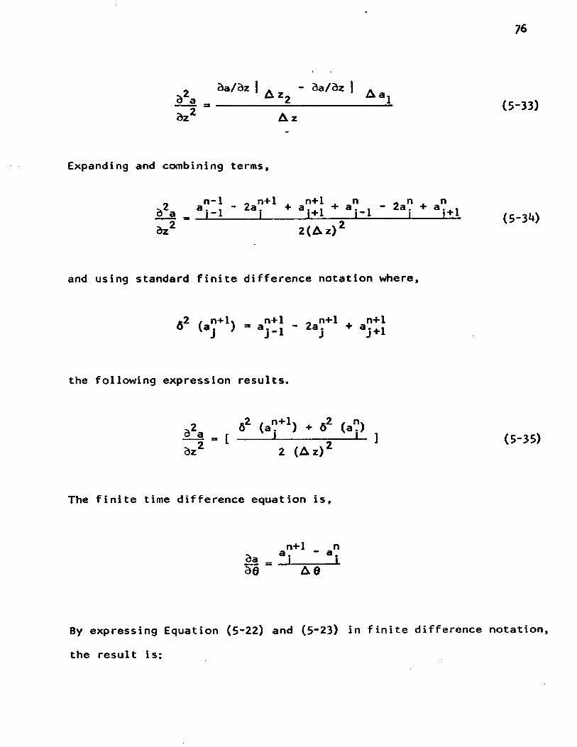
76
* da/dz | A - da/dz | A d a __________ A z 2__________ A a laz2 A z
Expanding and combining terms,
afadz2
n-1l lzL
- 2a?+l I + an+1i±Ln
1 1 - 1- 2a? na.i±i
2(Az)
and using standard finite difference notation where,
.2 / n + K n+1 „ n+1 . n+1(aj J aj-i ' j V i
the following expression results.
aiadz2
a2 ( a f ‘) + 82 (a1?)
2 (Az)2
The finite time difference equation is,
n+1 n* a - " a .da _ J_______ Lde A d
By expressing Equation (5*22) and (5“23) in finite difference
the result is:
(5-33)
(5-3*0
(5-35)
notation,

77
*2 t n+1* . *2 / n% n+1 n n+1 t n6 (a. ) + 0 (a.) a. - a a + a. n+i 1------ <- ] - [ 1 . - 1 J - [---;--L ] (5.36)2 (Az) 2 ' 1 A 8 2 ' j
82 (b"+I) ♦ J2 (b") b"+1 - b" b"+1 ♦ b"rq [ -----1--------=— *- J - q t - ‘- a a -1 1 - ( — — 5— L 1 •? (5-37)2 (Az)2 A 8 2 J
From the boundary conditions the values of a? and b? were known atJ J
time step n, for j = 0, 1, 2, ... J. Since the solution is simul-n+itaneous, first, values of bj had to be calculated using an explicit
finite difference method before the set of a? values could be calcu-J
lated. The values of a were inserted in Equation (5~37) to get a set
of late time values of b?+ *. The next time step the order in whichJ
the equations were used was reversed. The a values were calculated
and inserted in Equation (5“36) and the set of tridiagonal equations
were solved. This proceeded from one time step to the other up to
the time limit desired for the solution.
The initial row and column values of a are known from the boundary
conditions a = 0, at 0 = 0, any z > 0, and a ° 1, at z = 0, any 0 > 0.
Only the first row of b are known (b = 1) and the first column (for
8.0. 2, db/dz = 0) was calculated by assuming that values of b are
represented by a polynomial.
a + 0 z + y z ^ + 6z^ (5-38)
b° - a <5-38a)
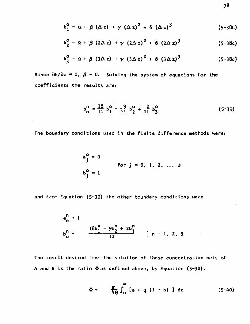
78
( A z ) 3 (5-38b)
6 (2Az)3 (5-38c)
6 (3Az)3 (5-38d)
b?
b ° * Of + j3 (2A z) + y ( 2 A z) 2 + 6 (2 A z ) 3
b ° - a + 0 ( 3 A z ) + y ( 3 A z ) 2 + 6 ( 3 A z )
Since d b / d z 83 0, =* 0. Solving the system of equations for the
coefficients the results are:
. n 18 . o 9 . o A 2 . o /cbo TI i " if b2 IT bj (5'39)
The boundary conditions used in the finite difference methods were:
a ? = 0
b? =» 1for j = 0 , 1, 2, ... J
and from Equation (5“39) the other boundary conditions were
n _ , ao • 1
18b" - 9b" + 2b" bo - lT 2 } n - 1, 2. 3
The result desired from the solution of these concentration nets of
A and B is the ratio $ as defined above, by Equation (5“30).
00*’ ?8 J'o ta + * (1 * b> ] dz

79
For the values of a and b calculated as described above, the integration
was performed numerically using Simpson's Rule. The upper limit of the
integration over z is out to but in reality this was carried out
only to large values of z, and the boundary conditions (a * 0, b = 1)
were approached.
With this model, $ can be calculated for any system which follows
the penetration theory, and compared with the experimental results
obtained for the particular system. Computing a single curve, which
is the numerical solution at a specific r and q for $ versus 9 (or yin)
out to its asymptotic value requires as long as k hours on the I.B.M.
7040 electronic computer. Figure 14 shows such a curve computed for
q = 10.37* and q = 4. 33 at r =• 2.91. The values of r and q's are at
the conditions used in series of runs at the higher sodium hydroxide
concentrations. This curve was used to get an estimate of the reaction
rate constant, k̂ ., which was the only parameter not measured, except
by this estimation procedure.
k. Infinitely Rapid Chemical Reaction
For given values of r and q the variable $ , in the solution*
described above, approaches an asymptotic value at large values of
9. This asymptote $ , r, and q has been obtained analytically bydDanckwerts® and by Sherwood and Pigford^ and presented by B r i a n ^
QP. V. Danckwerts, "Absorption by Simultaneous Diffusion and Chemical
Reaction." Transactions of the Faraday Society, XLVI (1950), p. 300QT. K- Sherwood and R. L. Pigford, Absorption and Extraction, (2nd
Edition; New York: McGraw-Hill, Inc., 1952), pp. 317”339-10B .Brian, o£. cit.

60
o
oo
Figure 14, Theoretical Solution for Penetration Theory Absorption with Second Order Irreversible Chemical
Reaction.
J*
s/W
b0A
°l

81
in the following form,
4> = 1/erf (o) a 1
(5-^1)
These are parametric equations, with o as a dummy parameter used to
generate values of $ versus q/r as shown in Figure 15. From this3plot it can been seen that the penetration theory solution for
infinitely fast chemical reaction can be expressed by the following
simplified relationships:
This simplification is particularly useful in packed tower
design calculations for absorption with fast reactions. The concept
is used in a later section on absorber design, and also used to
compare the data from the laminar jet with the predicted solutions.
5. Empirical Correlation of the Numerical Solutions
An empirical correlation of the general numerical solutions
facilitates the use of the penetration theory by greatly reducing
computation time, eliminating duplication of effort, and making the
4? =* 1 + q when r a 13 (5-42)
=' 1 + q/r when r j* 1 (5“43)

82
f t " 1
6 0
5 0
4 0
3 0
20
10 20 3 0 4 0 50q y r
Figure 15, Theoretical Solution for an Infinitely Fast Second Order Chemical Reaction
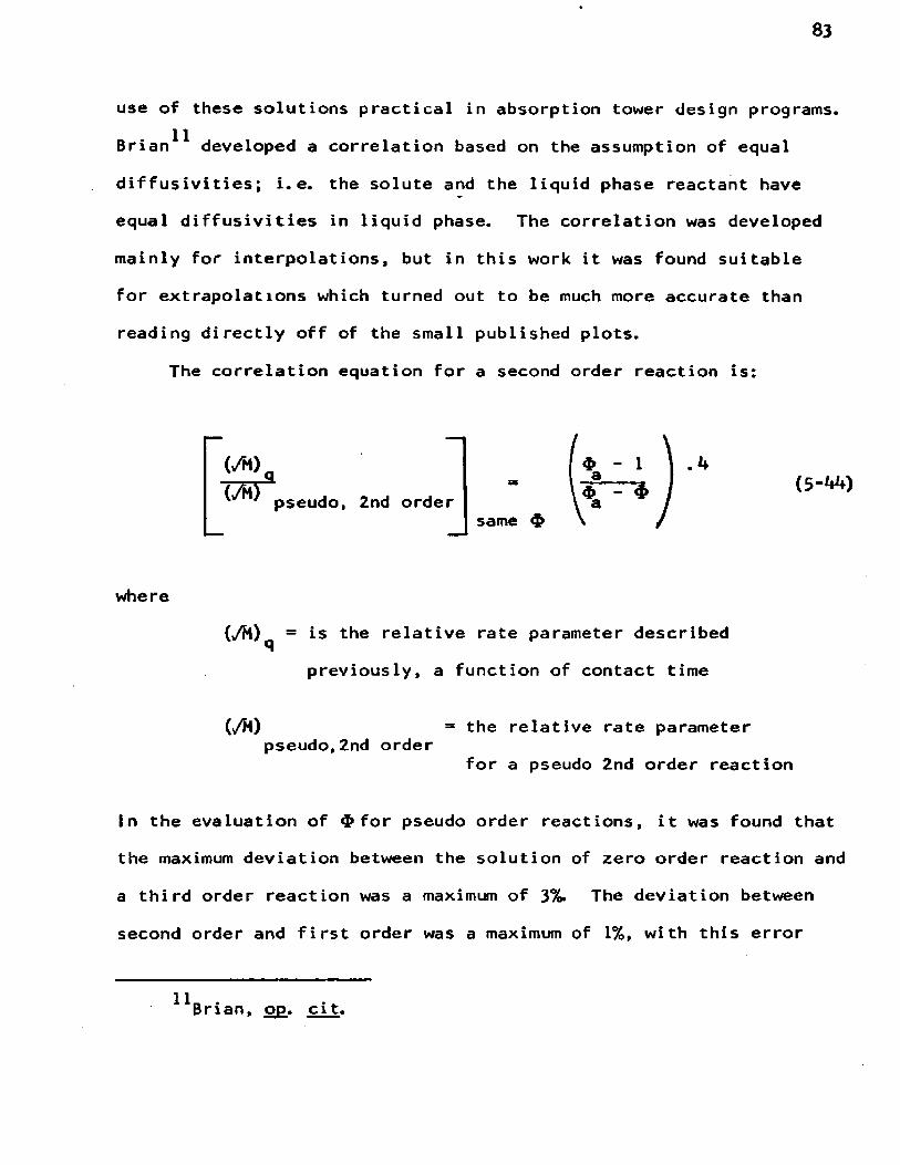
83
use of these solutions practical in absorption tower design programs.
Brian** developed a correlation based on the assumption of equal
diffusivities; i.e. the solute and the liquid phase reactant have
equal diffusivities in liquid phase. The correlation was developed
mainly for interpolations, but in this work it was found suitable
for extrapolations which turned out to be much more accurate than
reading directly off of the small published plots.
The correlation equation for a second order reaction is:
(/M),(/M> pseudo, 2nd order
- 1a$ - $ a
same $
where
(yM)q = is the relative rate parameter described
previously, a function of contact time
(s/M) = the relative rate parameterpseudo,2nd order
for a pseudo 2nd order reaction
In the evaluation of for pseudo order reactions, it was found that
the maximum deviation between the solution of zero order reaction and
a third order reaction was a maximum of 3%. The deviation between
second order and first order was a maximum of 1%, with this error
Brian, op. cit.

84
decreasing as the contact times (/M) increases. This small deviation
allowed the use of the analytical solution (Equation (5-45)) for pseudo
first order as a good approximation for the pseudo second order solutions,
which requires a numerical analysis solution. The analytical solution12 13for the absorption with a pseudo first order chemical reaction is; ’
*a = /M [1 + 8M 1 erf * eXp (" }
The use of this expression makes the correlation expression even more
versatile, because now values of # versus ,/M can be obtained in a very
short time by a computer as part of a design program. The solution of
these values require a successive approximations, since $ cannot be
solved for explicitly from Equation (5-44) and (5~45). The details
of this iterative technique is given in Appendix E.
6. Extension of Theory to Packed Absorber Design
The design of packed absorbers for“gas absorption with simultaneous
chemical reaction can be readily accomplished if the mass transfer process
over the entire tower is gas phase limiting. Usually the liquid phase
reactant will drop below a certain level, the reaction effect will
decrease, and the liquid phase resistance will become significant.
This shift could make the tower operation unsatisfactory if the design
was based on strictly gas phase limiting assumption. If the reaction
12Sherwood and Pigford, op. cit.
^Brian, o£. cit.

85
v
rate is slow, or moderate, the liquid phase resistance may be significant
throughout the column.
When the reaction is very fast the tower design can be accomplished14by a simple technique presented by Secor and Southworth. The method
will be called the integral method, to distinguish it from the differ
ential technique developed in this work.
a. Integral Method
The integral method considers the absorption process occurring
in three zones: (1) the surface reaction zone with no liquid phase
resistance, (2) the interior reaction zone, where the mass transfer
is influenced by diffusion of liquid reactant and gaseous solute, and
(3) physical absorption after the liquid reactant is exhausted. The
shift from surface reaction zone to interior reaction occurs at a
critical concentration which can be evaluated readily. Actually the
change is continuous and can be handled another way. The derivation
of the equations are straightforward and is described in Appendix F.
The resulting integrated equations for the solution of packed height
are given here as an introduction to the next method. The height of
the surface reaction zone, which is at the top of the column as shown
in Figure 16, can be obtained by integration of the following equations.
A material balance for a differential length of tower is given by
V " fiM dh (5‘1*6)111R. M. Secor and R. W. Southworth, “Absorption With an Infinitely
Rapid Chemical Reaction in Packed Towers,,r A. I Ch. E. Journal, VI! (1961), p. 705.

86
• *u oS N
IU
K N
6 m Lm
FIGURE 16 , REPRESENTATION OF THE TH REEABSORPTION ZONES IN A PACKED TOWER IN WHICH THE REACTION A + B -» AB TAKES PLACE AT AN INFINITELY RAPIDRATE

87
and the rate equation is
NA a » kGa P (y - 0) (5-47)
because there is no liquid phase resistance, and the bulk liquid phase
concentration of the gaseous solute is zero since the reaction is
immediate. Assuming (G /kra P) is constant one gets,M u
The height of the interior reaction zone is obtained by applying the
same material balance represented by Equation (5“46), The rate expression
for the interior reaction zone which is obtained by manipulation the
Hatta film theory equation and applying initial conditions to an overall
material balance over the interior reaction zone section can be simplified
to,
The constants (X and 0 contain physical parameters such as diffusion
coefficients of A and B. The simple expression can be integrated to
obtain the height of the interior reaction zone. Starting with the
following differential equation,
(5-48)
NAa s k6aP (ay + 0) (5-49)
gm 5h - V p y + * (5-50)
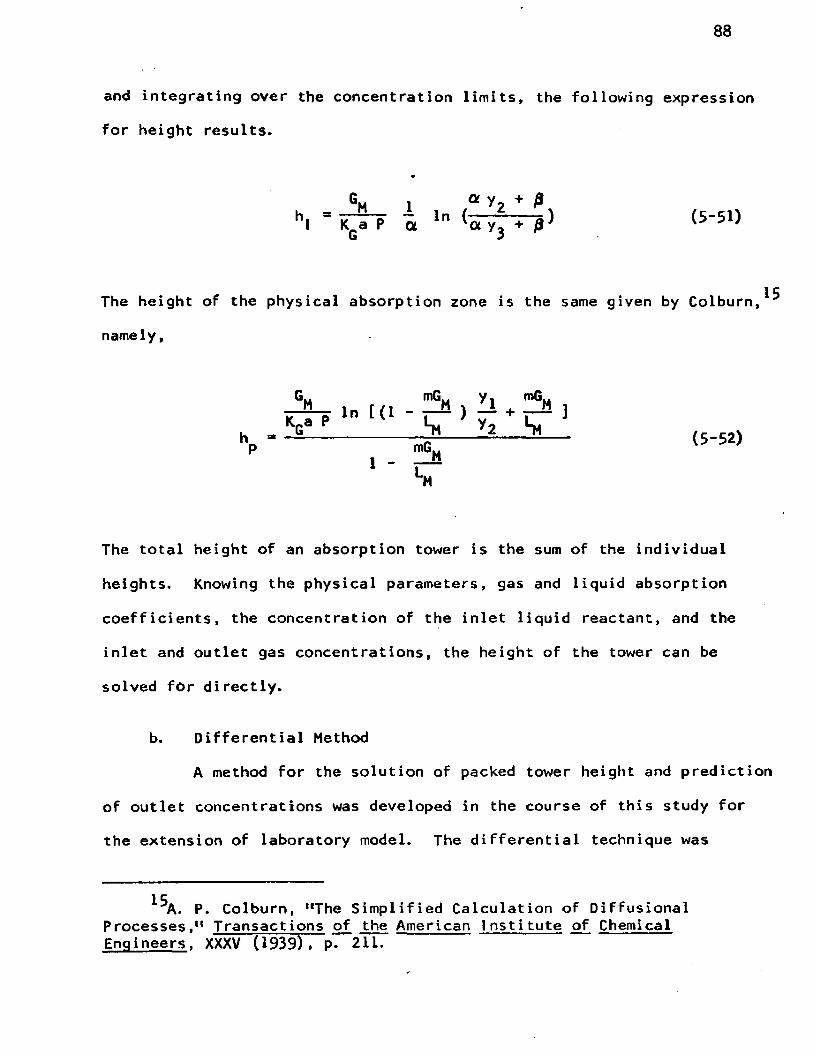
88
and integrating over the concentration limits, the following expression
for height results.
The height of the physical absorption zone is the same given by Colburn,*"*
namely,
K T T l n t(l ^ +
^ — £ a * « - » >
' ■
The total height of an absorption tower is the sum of the individual
heights. Knowing the physical parameters, gas and liquid absorption
coefficients, the concentration of the inlet liquid reactant, and the
inlet and outlet gas concentrations, the height of the tower can be
solved for directly.
b. Differential Method
A method for the solution of packed tower height and prediction
of outlet concentrations was developed in the course of this study for
the extension of laboratory model. The differential technique was
P. Colburn, ‘The Simplified Calculation of Diffusional Processes,11 Transactions of the American Institute of Chemical Engineers, XXXV (1939), p. 211.

89
patterned on the surface renewal penetration theory. In the solution
a differential element of the tower roughly equal to the height of a
piece of packing was chosen. This concept is used to get a value of
$ for a certain contact time, and to obtain a measure of the effect
of reaction on the gas absorption rate.
A column of unknown height was incremented in differential
elements representing changes in the bulk gas phase concentration.
Figure 17 shows the packed absorber schematically. With terminal
conditions known, and starting at the top of the column, the first
initial increment was considered. A material balance around the
element was used to get the liquid phase concentration leaving the
element. The next step was to consider the interfacial concentration
of the gaseous species. For the limiting case, with very concentrated
liquid solutions of reactants the interfacial concentration was essen
tially zero, and the computer method considered the solution as a very
small but finite number. The calculation of the interfacial concen
tration was a trial and error procedure since it is a function of mass
transfer rate; and, the liquid phase mass transfer rate is a function
of the interfacial concentration as indicated by the parameter used
in the numerical penetration theory solution, q = C_ /C. . As showno i
in Equation (5"**3) , q is also used to evaluate $ when the reaction
rate is infinitely fast.
$ - 1 + /rqa where q =* Cg /C^ o i
(5 -53)
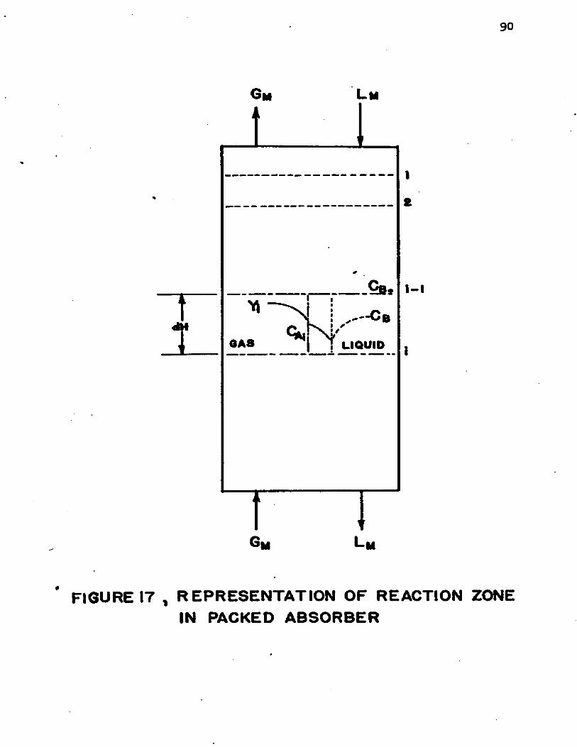
90
Gm L m
l-i
V : " - ° b< V N KT LIQUIDOAS
* FIGURE IT , R EPR ESEN TA TIO N OF REACTION ZONEIN PACKED ABSO RBER

91
The procedure to evaluate, CA , the interfacial concentration, is asi
follows:
(a) estimate C assuming no gas phase resistance using Henry's Lawi - .
constant.
CA. “ H/ybulk
(b) evaluate $ f r o m the empirical correlation by estimating q from
the initial calculation of C. , q ■ /C. .i o i
(c) Calculate a new estimate of C. , using the l v a l u e in the massi
transfer expression.
Na = kLa (CA - 0 ) = kQa (y - y.) (5-5*0
= $ k ° a CA = kGa (y - HCA ) (5-55)
Solving for C. , one gets i
4
*va yC - --- 5 - ® -------- (5-56)*i $ k£a + H kQa
(d) The late value of C. is used again in (b) to calculate a newi
C ; and the process repeated until the value of K„a convergesn • ^to a test limit.

92
(e) In (b) the evaluation of $ requires a trial and error procedure
described in Appendix E.
The solution proceeds in this manner from one increment to the next
storing the late values of K^a and y.
The solution for the height of the column is based on the following
derivation.
"a - gh £ - V (y - 0) (5'57)
Solving the equation for the height,
h “ J l j S - d X (5-58)Kra y
Since K^a is a variable and not an explicit function of y, the equation
must be integrated numerically. Using Simpson's rule the stored values
of K^a and y for each element are summed to give the height of the
tower. A computer program was written in FORTRAN IV language for an
l.B.M. 7040 digital computer based on the above method.
The computer program in Appendix G was used in predictive design
and compared with absorption data obtained for the National Council
for Stream Improvement by Jensen. ^ The absorption of the dilute
methyl mercaptan-air mixture was obtained in a 2 in. diameter tower
A. Jensen, Final Report on Absorption of Odor Producing Sulfur Compounds, to National Council for Stream Improvement, December 31, 1964.

93
packed with 1.7 feet of 1/k inch Intalox saddles. The tower with
usual auxiliary equipment was operated at twelve levels of sodium
hydroxide concentrations. Multiple chromatographic analyses were
made to determine inlet and outlet concentrations. Initial eval
uation of the data was limited to the calculation of the K^a, which
wasn't constant and could not be scaled up, since it was based on
the following integral
true only for the limiting cases where gas phase resistance controls
and when reaction effects are negligible. The data could not be
scaled up unless a more realistic model was developed. Using the
data obtained in laboratory study: second order mechanism,
S H ’ ^OH” ’ an< ̂ solubility, a successful model was developed.
Figure 13 shows the original data.
h
Kq® f y(5-59)
which defines K^a only if the ratio G^/K^a P is constant. This is
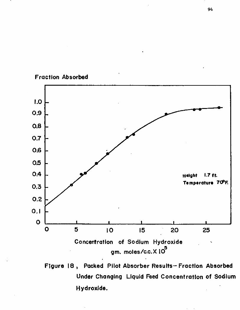
94
Fraction Absorbed
1.0
0.9
0.80.7
0.6
050.4 Height 1.7 ft.
Temperature 7CPF.0.3
0.20.10
0 5 251 0 2015
Concentration of Sodium Hydroxide5
gm. moles/c.c.X 10t m
Figure 1 8 , Packed Pilot Absorber Results-Fraction Absorbed
Under Changing Liquid Feed Concentration of Sodium
Hydroxide.

CHAPTER VI
DISCUSSION OF RESULTS
1. Carbon Dioxide and Water
The laminar liquid jet was designed to contact the absorbing
liquid with a gas for a short period of time under conditions in which
the jet mass transfer area, contact time, and absorption rate could
be determined. The equipment was designed according to the best
engineering technology available, particularly orifice design and
precision machining. The mass transfer area was determined by cali-
bration with a travelling microscope as described in the experimental
section in Chapter IV. The contact area was determined to be free of
ripples by visual examination under a microscope. The gas absorption
rate was determined accurately with a bubble film flow meter also
described previously. The contact time was calculated by using a
measured diameter and the assumption of plug flow. This assumption
had to be justified before equipment reliability and calibration of
the technique was ascertained. Using a system which had previously
been well investigated, regarding the determination of the diffusion
coefficient and solubility, the instrument was evaluated. Any discrep
ancies in the results was attributable to the errors in the flow regime
assumption and the method of calculation of contact time. Carbon
dioxide and water suited these criteria.

96
The use of a square edged diaphragm orifice produces laminar
liquid jets with only a slight initial boundary layer retardation.
This effect is insignificant except under the shortest contact times.
Bell mouthed orifices produce considerable boundary layer retardation
and this shows up in the plot of the data. Figure 19 shows the effect
as determined by Raimondi and Toor* for a bell mouthed orifice on the
carbon dioxide-water system. Knowing the velocity profile for the bell
orifice, a correction can be added, which is based on approximate
boundary layer theory solutions. The use of thin-square edged orifices
eliminates the need for the correction and a test of the data usually
shows that the plug flow assumption is adequate.
In order to test the penetration theory solution, the best value
for the diffusivity of CO- in water at 25°C was used. The most recent_c2 -c3 2
values for D are: 1-97 x 10 and 1.95 x 10 cm./sec. The mean2value of 1.96 x 10 cm. /sec. was taken and used for comparison in
this work. The solubility of C0^ in water was taken to be . 759 cc.
(NTP) per cc.^ With these two physical constants, Equation (3~20)
P. Raimondi and H. L. Toor, 111 nterfaaial Resistance in Gas Absorption,“ A. I. Ch. E. Journal, V (1959), p. 86.
ZJ. F. Davidson and E. J. Cullen, "The Determination of Diffusion Coefficients for Sparingly Soluble Gases in Liquids,u Transactions of the Institution of Chemica1 Engineers (London), XXXV (1957), p. 51.
^T. R. Rehm, (M.S. Thesis, University of Washington, I960).1+J. K. A. Clarke, "Kinetics of Absorption of Carbon Dioxide in
Monoethanolamine Solutions at Short Contact Times," Industrial and Engineering Chemistry - Fundamentals, I 11 (196*+) » p. 211.
5International Critical Tables, Vol. 3. , (New York: McGraw-
Hill, Inc. , 1928), p. 259.
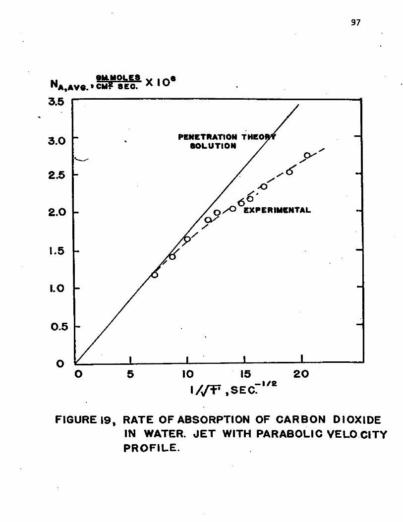
97
yU.MOI.E8 >N A ,A V 8 .» CM? 8 EC. A 1 u
3.5
PENETRATION THEOI SOLUTION /3 .0
2.5
>sO e x p e r im e n t a l2.0
1.5
1.0
0 .5
O 2015, _ — 1 / 2
IA/T' ,S E C .
FIGURE 19, RATE OF ABSORPTION OF CARBON DIOXIDE IN WATER. J E T WITH PARABOLIC VELO CITY P R O F IL E .

98
was used to predict the penetration theory results.
NA = 2 (C*) (3-20)
The equation for the theoretical line, after insertion of the constants,
observations over Ik runs were made at various contact times. The
contact times were controlled by varying the jet length and liquid
flow rate. Varying the jet length also varies the mass transfer
area so that system errors and interdependence between the variables
can be checked out. The tabulated data is given in Appendix 8, and
the results are plotted in Figure 20.
The results obtained with the laminar jet follow very closely
the theoretical line of the penetration theory result. The maximum
deviation is at the high values of l//t' which was short contact
times in the order of 3 milliseconds. At these short contact times
and jet lengths, the boundary layer retardation and the end effects
were the jet meets the receiver, is obviously significant. The other
points are linear and distributed about the theoretical line.
Na = (2)(3. 39 x 10 5 gm. mole cc.
Na - 1. 70 x 10"7 (6-la)
The system C0^ and water was studied at 25°C. A total of 66

99
Na ,avo. ‘ ICP
4
3
2
oo 5 10 15 20
i / y r 1 . s e c : i/2
FIGURE2 0 , ABSORPTION OF CARBON DIOXIDE INWATER AT 25* C.

100
At this point the results from the Ct^^Water system was taken as
sufficient proof of the accuracy of the apparatus, and the laminar
jet was used with confidence on unknown systems. The method of
calculation of contact times was also accurate.
2. Sulfur Dioxide and Water
in order to test the laboratory facilities and the experimental
technique for the operation with toxic gases, the system sulfur dioxide
and water was tested. Using sulfur dioxide, brought in another magnitude
of difficulty in the experimental technique, since all purging and
excess gas vents had to be controlled. The liquid effluent from the
laminar jet was collected and transported to an external waste disposal
point. The use of the sulfur dioxide also provided the means for a
check on the bubble film flowmeter because of the availability of an
accurate titrimetric method for sulfurous acid.
The rate of absorption of SO 2 into the liquid jet was measured by the bubble film flowmeter. The liquid effluent with the absorbed SO2 was piped through a closed system to an automatic pipette. Three
aliquots of the liquid effluent was drawn into solutions with a known
equivalent weight of iodine. The excess iodine was titrated with
thiosulfate and the SO2 determined by difference. Knowing the liquid
rate, the amount absorbed was calculated and compared with the quantity
measured by the bubble film gas burette. Agreement was satisfactory
as shown in Table II, with the discrepancy caused by some loss of SO2 in the titration step.
The data obtained in the study on sulfur dioxide is plotted in
Figure 21. As predicted by the penetration theory (Equation (3"20))
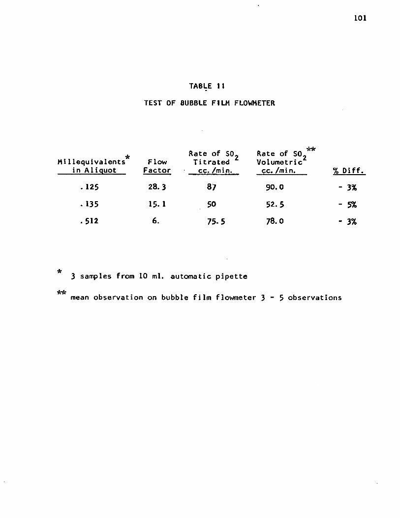
101
TABLE II
TEST OF BUBBLE FILM FLOWMETER
^ Rate of S02 Rate of SO^Mi 1lequivalents Flow Titrated Volumetric
in Aliquot Factor cc. /min. cc. /min.
.125 28.3 87 90.0
.135 15. 1 50 52.5
.512 6. 75-5 78.0
% Diff.
- 3%
- 5%
- 3%
3 samples from 10 ml. automatic pipette
mean observation on bubble film flowmeter 3 - 5 observations

102
0M.M0LE8 6N a .AVO. » C M f- 8E 0. * IU
15
PREDICTED BY THEORY y
1 0
5
OO 5 10 2 015
W f • s e c " ,/£
FIGURE 21 , ABSORPTION OF SULFUR DIOXIDE IN WATER AT 2 5 * C.

103
the plot of versus l//t' gives a linear relationship. Literature
values for the diffusion coefficient vary widely probably due to the
reaction effects of the SO 2 with water and also the very high solubility which would give rise to concentration effects on the diffusion
coefficient. Cited values of range from 2.05 x 10 ^ to 1. 7 x 10 2cm. /sec. As a result both values were used to calculate the theoretical
lines. The solubility was taken from some recent work by Rabe and
Harris^ which should be accurate. A plot of the isotherms are presented
in Figure 22. At 25°C and 754 nim. of Hg the solubility of SO2 1-30 x 10 ̂
gm.-moles/cc. (8.3 gms./lOO gms. I^O). This differs considerably from
some old data^ which lists the solubility as 1.43 x 10 ^ gm. -moles/cc. ;
the value which is usually found in the handbooks. Using these two
physical parameters, the diffusion coefficient and the solubility, a
theoretical line giving the lower estimate of flux (using D_n =*4 V A“5 21. 7 x 10 cm./sec.) was calculated from the following expression
sA = 6.05 x io"6 y T " (6-2)
The theoretical line giving the higher estimate was calculated from~5 2Equation (6*3) where the = 2. 05 x 10 cm./sec. was used.
Na = 6.64 x 10"6 / I (6-3)
^A. E. Rabe and J. F. Harris, "Vapor Liquid Equilibrium Data for the Binary System, Sulfur Dioxide and Water," Journal of Chemical and Engineering Data, VI11 (1963), p. 3-
F̂. Schoenfeld, "Ueber den Absorptions Coefficient en den Schwefligen Saure, des Chlorsund Schwefelwasserstoffs,,r Annalen der Chemie und Pharmacie, Justus Liebigs, XCV (1855), pp. 1-23.

104
PA R TIA L P R E S S U R E , m m . H t .
3 0 I O
70C
6 0 0
0 * C5 0 0 -
40C
3 0 0
6MS. S O * / 100 6MS. WATER
FIGURE 2 2 ,SOLUBILITY OF SULFUR DIOXIDE IN WATER
105
These two lines are plotted comparitively against the data obtained in
this study from 14 runs at 25°C (see Figure 21). A total of *+5 absorption
rate observations were made over these 14 runs and the point averages
are plotted. It is apparent that the higher values of the diffusion
coefficient are erroneous and a value of D__ closer to 1.8 x 10 ^2 . 2 -c8cm. /sec. is a better value. There is a literature value of 1.83 x 10
which fits the data better. Since the laminar jet is a prime measurementg
of the diffusion coefficient, as explained by Himmelblau, we can put10 -5some additional certainty in the value of as being 1.8 x 10
2cm./sec. Additonal varification should be done, but since this was
not the main purpose of the investigation, the work on SO2 was used as another check before using the laminar jet technique on unknown
systems, namely methyl mercaptan and water.
3. Methyl Mercaptan and Water
Methyl mercaptan data on solubility and diffusion coefficient is
sparse or non-existant. In order to evaluate the mass transfer effects
of methyl mercaptan in water, the solubility of the compound in water
was measured at 25°C. This was done using a dynamic system, where the
methyl mercaptan gas was bubbled through two gas scrubbers containing
a known amount of water in a thermostated bath. Steady state was
reached in less than 30 minutes. The liquid in each bottle was
D. W. Peaceman, “ Liquid Side Resistant in Gas Absorption With and Without Chemical Reaction," (Sc.D. Thesis, Massachusetts Institute of Technology, 1951).
gD. M. Himmelblau, "Diffusion of Dissolved Gases in Liquids," Chemical Reviews,LXIV (1964), pp. 527“550.
1 0 l b id . , p. 540.
106
titrated separately using iodometric technique. Correction for
barometric pressure and water vapor pressure was applied, and the
solubility calculated from the equivalent iodine consumed. The
method was relatively precise (± .7%) and considered accurate enough
for engineering data. The solubility of methyl mercaptan of 2.45 *
10 gm. mole/cc. was used in the calculation of the diffusion
coefficient and mass transfer coefficient based on the penetration
theory equations.
The experimental procedure for the absorption studies was
essentially the same as used with the two previous systems described
above, except for the obnoxious odors accompanying any accidental
release. A system of gas collection and scrubbing using potassium
permanganate solutions was effective in controlling emissions in
the laboratory.
The result from the runs of methyl mercaptan in distilled water
is tabulated in Appendix C. The data is plotted as the average
absorption rate versus l//t' in Figure 23. The data can be corre
lated by a straight line through the origin, showing this system
also follows the penetration theory. The maximum deviation occurs,
as it did in the other two systems, at the lowest contact times.
The equation for the straight line through the data is;
(6-4)
Since the proportionality term equals 2 (C ) , the diffusion

107
Kl e i l . MOLES v , ^ 6N a 4AVO. 1 QAIVSCB. ^ I ®
20
o 5 10 15 2 0
i//T, S E C r 1'*
F IG U R E D ABSORPTION OF METHYL MERCAPTAN IN
WATER AT 25* C.

108
~5 2coefficient can be calculated. The coefficient is 1.03 x 10 cm. /sec.
A prediction of the diffusion coefficient using the Wilke-Chang corre--5 2 11lation gives D “ 1.53 x 10 cm. /sec., not a bad comparison considering
the correlation predicts for H^S as 1.9 x 10 ^ versus the experimental ~5 2value, 1.5 x 10 cm./sec. Both of these compounds are slightly ionizing
and have the common sulfide molecule, which may account for the failure
of the prediction equations.
1*. Methyl Mercaptan Absorption in Aqueous Sodiurn Hydroxide Solutions
For the system methyl mercaptan-aqueous sodium hydroxide solutions,
a total of 48 runs at 6 sodium hydroxide levels were completed. The
results of each run was converted into an absorption coefficient
(tabulated in Appendix D). The results are plotted in Figure 24 and
compared to baseline coefficients for methyl mercaptan into water. The
variable O w a s obtained by ratioing the k^ for chemical absorption, to
the coefficient k° for absorption without reaction (represented by the
lowest line). The average of the $'s along with the range calculated
from this data are plotted versus the sodium hydroxide concentration in
Figure 25. Note how the effect of reaction increases the absorption
coefficient some twenty fold over the range studied.
a. Ionic Reaction
In Chapter III, Section 5> the postulated ionic reaction
between the dissolved methyl mercaptan and the hydroxyl ion was
described. Equation (3“23) showed;
11 - 5 2 The Othmei— Thakar correlation gives D ■ 1.5 x 10 cm. /sec.

109
100L CM./MIN.
to86
4ABSORPTION IN WATER
2
100010 20 4 0 6 0 80100l / f . SEC.
KEY Q Na OH (Cq )• 10.87 2 .0 4 N.V 4 3 3 1 .0 6 N.+ 2.S1 .6 4 N .m, 0 .4 9 .12. N.o 0.041 .01 N.A 0 .0 0 4 9 .0 012 N.
FIGURE24.ABSORPTION COEFFICIENTS OF METHYLMERCAPTAN IN AQUEOUS SOLUTIONS OF SODIUM HYDROXIDE.
/

110
FIGURE2 ^ EFFECT O F SODIUM HYDROXIDE CONCENTRATION ON ABSORPTION RATE.
SODIU
M HY
DROX
IDE
CONC
ENTR
ATIO
N

Ill
CH3SV ) + 0H(i) - CH3S(X) + H2°(j6) «'23>
The stoichiometry is usually written to show a salt reacting with the
weak acid to form another salt, sodium mercaptide. The mercaptide
salt along with sodium hydroxide is completely ionized and Equation
(3“23) showing the ionic species instead of the molecular salts
represents the mechanism by which the exchange of a proton occurs.
The exchange of a proton should be quite rapid. The frequency of
collision of ions in solution is estimated from kinetic theory to be11 12 about 10 liters/mole-sec. According to the collision theory only
a certain fraction of the collisions will result in a chemical combi
nation (a proton exchange) since not all of the collisions will have
the required activation energy. There may also be a steric factor,
but it is not likely in this case. The above consideration should
lead one to conclude that the reaction in Equation (3~23) would
proceed quite rapidly and the data was tested to that effect.
Using the asymptotic solutions for the penetration theory
described in Chapter V, Section 1*, for absorption with an infinitely$
fast chemical reaction, the data was plotted comparatively. The
theoretical solution is specified by the parameter r which is the
ratio of the diffusivity of the solute gas over the diffusivity of
the ionic liquid phase reactant. This value of r was evaluated using
Equation (3“28) which considers the solute B to be the OH ion. The
12M. Eigen, ‘'Methods for Investigation of Ionic Reactions inAqueous Solutions With Half-Times as Short as 10~9 Sec. Discussionsof the Faraday Society. XVI I (195*0 . P* 19***
112
value of “ 2.91. The variable V was correlated by the theoretical
solution for infinitely fast reaction at the higher sodium hydroxide
concentrations (see Figure 26). The ranges of Vindic a t e d in the
ordinate direction may be due to error, but are more probably due to
the effect of changing contact times on the absorption rate. The
above analysis leads us to conclude that the rate of the postulated
mechanism is very fast. However, further analysis yields an estimate
of the rate of the forward reaction.
b. Estimate of the kp, the Forward Reaction Rate Constant
An estimate of the reaction rate constant was obtained by
applying the numerical solutions of Equations (3“29) and (3“30) for
the specific r and q's which were studied. The result of the numerical
solution for q = 10.37 and q = 4 . 3 3 are shown in Figure 27- The V s are
specified by experimental data, as well as other parameters. The only
unknown physical constant was k p , which is a part of the variable
plotted on the abscissa, M.
y ^ pch3sh sCH-SH I)v/M = Y --------- £ (3-32)
k KL
The plot was entered at the ordinate with values of V, and the values
of M were read at the curve intercept. The values of kp were calculated
for each V and the results are tabulated in Table 111. The best
estimates are obtained for q = 10.37 because of the position from
which the values are obtained on the curve. The values from the

113
$-1
Theoretical Solution for r = 2.92
4 0 6 0 8 0 1 0 . 2 0 . 30.2.01.00.6q / r "
FIGURE 26 , ABSORPTION RATE COMPARED WITH
THEORETICAL SOLUTION FOR INFINITELY
FAST SECOND ORDER REACTION.

10080
60
40
$ ■ rwclkxO/t̂lwlthout rcocHan)r •Q 4 (Bo/Acm̂ h )
/ ^ T A :20
ReodPorom«t«r ond Estimate kr
60. 80 100.40.20.4.02.00.2 04<J M
FIGURE 27, ESTIMATION OF FORWARD REACTION RATE CONSTANT
114

115
TABLE III
REACTIONS RATE CONSTANTS
oCL
10.37
cm. /min. $ & *v
1.5 16. 7 1*7. 5.3 x 10⁴ liters gm. -mole-sec.
1. 7 16. 2 1*0. 5. 1 x 10⁴ ir
1.9 15.8 36. 5.0 x 10⁴ n
2. 1 15. 7 36. 6. 1 x 10⁴ ir
3.0 11*. 7 27- 7.0 x 10⁴ ir
Avg. 5.6 x 10⁴ @ 25°C
1.5 8. 06 50. 13-9 x 10⁴ II
1. 7 7. 95 32. 7. 8 x 10⁴ II
1.9 7-9 26. 6. 2 x 10⁴ II
2. 1 7.9 26. 7. 6 x 10⁴ II
3.0 7-67 23.
Avg.
12.0 x 10⁴
9. 5 x 10⁴
II
(/M)2 (k°)2
(°CH3SH^ *c b )o
using; C_ =* .00251* gm. moles/cc. at q = 10.37iJ2
°CH SH = cm./sec.

116
second curve, q = 33 are taken from a near asymptotic section, and
subject to reading errors. The results from this second curve are
shown for comparison and are of the same order of magnitude, even ifo Unot nearly as constant. The value of kp at 25 C is 5 x 10 liters/
gm.-moles-sec. , and in the range of ionic reaction rates. A crude
estimate of the reaction rate between chlorine and sodium hydroxide£
obtained via another technique was given as 10 1iters/gm.-mole-sec.
(10^ for CHjSH - NaOH from this study as compared to 10^ for Cl^ -
NaOH.
5. Extension of the Model to a, Packed Absorber
A method of calculation for sizing packed absorbers was described
in the previous chapter. These calculations were based on the appli
cation of the penetration theory to describe the effect of chemical
reaction between methyl mercaptan and sodium hydroxide on the rate of
absorption. The use of a multiplier, <$, called an enhancement factor,
in scaling the liquid phase coefficient, allows the evaluation of the
overall resistance to absorption, or an overall coefficient, K„a.U
M <6-5)K.a k.a , , oG G kLa
The factor, $, is a function of the reaction rate, concentration of the
liquid phase solute and reactant, and the contact time of an element of
fluid as described in the development of the theory. It can be evaluated
easily in the limiting case where $ is an asymptotic value, or more
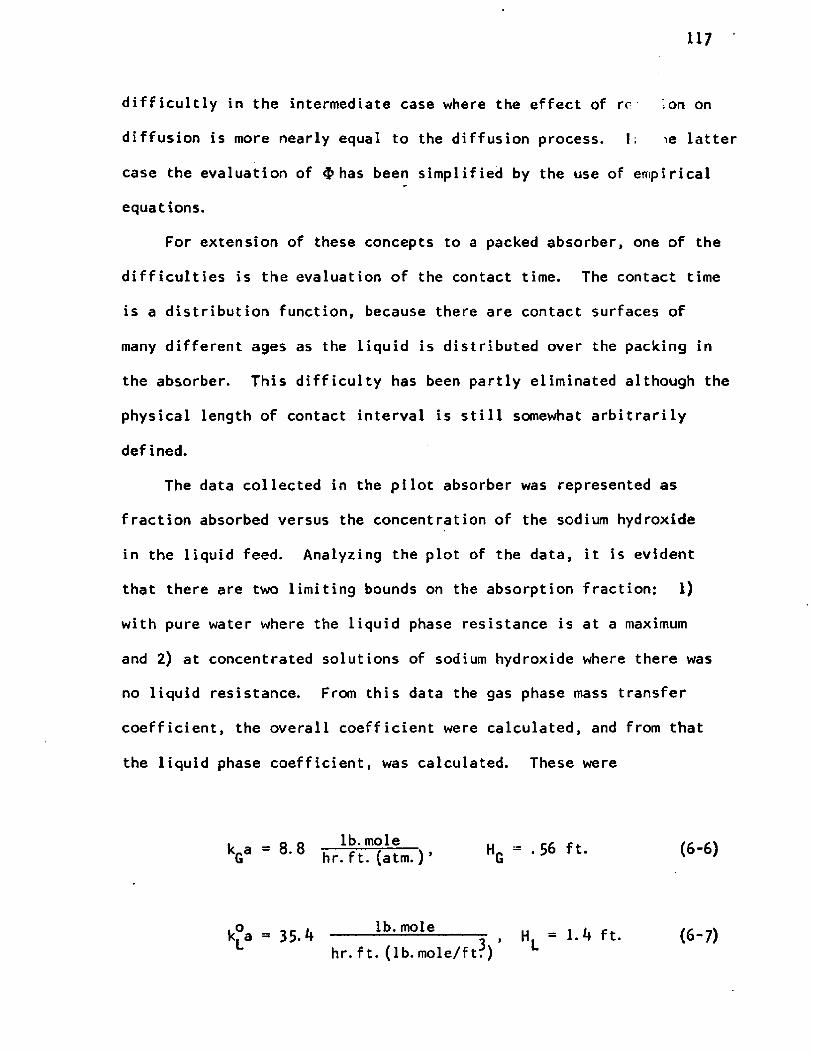
117
difficultly in the intermediate case where the effect of re ;On on
diffusion is more nearly equal to the diffusion process. 1; ie latter
case the evaluation of $ has been simplified by the use of empirical
equations.
For extension of these concepts to a packed absorber, one of the
difficulties is the evaluation of the contact time. The contact time
is a distribution function, because there are contact surfaces of
many different ages as the liquid is distributed over the packing in
the absorber. This difficulty has been partly eliminated although the
physical length of contact interval is still somewhat arbitrarily
defined.
The data collected in the pilot absorber was represented as
fraction absorbed versus the concentration of the sodium hydroxide
in the liquid feed. Analyzing the plot of the data, it is evident
that there are two limiting bounds on the absorption fraction: 1)
with pure water where the liquid phase resistance is at a maximum
and 2) at concentrated solutions of sodium hydroxide where there was
no liquid resistance. From this data the gas phase mass transfer
coefficient, the overall coefficient were calculated, and from that
the liquid phase coefficient, was calculated. These were
k_a = 8.8Ulb. mole HQ = . 56 ft. (6-6)hr. ft. (atm. ) ’
k°a = 35-1+ lb. mole H l = 1.4 ft. (6-7)hr. ft. (lb. mole/ft?)

118
The use of contact time in the penetration theory solution was
eliminated by making use of the penetration theory definition of the
liquid phase mass transfer coefficient.
(6-8)
or,
(6-8a>D
This k° is used in the definition of the parameter M, from which
$ can be evaluated, as follows
* kF C» °A „0 3 "f CB 1 = i [ . o2 1 " i tHj (3-32)
L
and
/M =CB °A Bo A
In order to get a value of k£, from the experimentally determined k^a,
the effective area of mass transfer was taken to be 50% of the total
119
area of the Intalox packing. Various correlations of effective areas
of the different packings have been published. Correlations on Raschig
rings show 22% to 1*0% effective area. Usually these effective areas
are calculated from mass transfer data which measure absorption in
stagnant and moving liquid elements. The use of this type of calcu
lation can lead to errors when reaction is occurring, because absorption
may occur equally effectively over the entire wetted area. The wetted
area is almost always greater than the calculated effective area. The2 3total area for 1/ty* Intalox is around 300 ft./ft. based on extrapolations
from data on Berl saddles, and other Intalox packing size. Lacking
empirical correlations, and base data on total packing surface, the
figure of 1/2 was arbitrarily chosen as the upper limit. In this
system where the reaction rate is very fast, the use of smaller
effective areas would give a longer contact time. The solution for
the enhancement factor $ is near the asymptotic region, so an error
in the assumption of effective area does not greatly affect the final
solution.
The evaluation of the forward reaction rate constant, kp, for use
in the parameter M, was described above. The diffusion coefficients of
methyl mercaptan was measured as part of the absorption study with
water, and the evaluation of the diffusion coefficient of hydroxyl
ion as described in Appendix A.
The concentration of the hydroxyl ion in the liquid phase at
various points of the column, was evaluated by means of a material
balance considering the methyl mercaptan completely reacted.
120
Having these physical constants an enhancement factor, was
calculated at the various increments in the column. The solutions
was "cut and try" because the value of the interfacial concentration
of dissolved solute could not be calculated until rate of mass
transfer was determined.
Calculations on the packed tower was carried out on an I. B. M
7040 digital computer according to the method described in the previous
chapter and the FORTRAN IV program which is included in Appendix G.
The program was used to predict the change in absorption fraction and
compared well with the data from the pilot absorber (see Figure 28).
The method of calculation can be used to scale data from pilot
absorbers and to size chemical absorbers with fast chemical reactions.
The technique should be suitable for intermediate reactions providing
some basic data is measured or can be predicted.
The liquid phase and gas phase, height of transfer units were
calculated for the pilot absorber using published correlations for
the specific tower packing and flow characteristics. The H* for thisGsystem was calculated to be 0. 55 ft. based on work with a highly
13 14soluble system. Extrapolating another correlation based on the
absorption of methanol in water for 15 mm. Raschig rings, predicts
Hg to be 0. 7 ft. The experimental data on the packed absorber indi
cated the height of a transfer unit (Hg) in the case of gas phase
^J. H. Perry, Chemical Engineers1 Handbook, (4th Edition; New York: McGraw-Hill, Inc., 1963), 14-19-
14F. Yoshida and T. Koyanagi, "Mass Transfer and Effective Interfacial Areas in Packed Columns," A. I. Ch. E. Journal. Ill (1962), p. 309.

121
F ra c t io n Absorbed
1.0
0 3
0.80 .7
0.6
0 . 5
0 .4
0.3
0.2 0.1
O
-Q—
B
10 15 20 2 5
C o n c e n tra t io n o f Sodium Hydroxide gm. moles /c.c.X 10 '
F ig u re 2 6 , T h eo re t ica l Solutions fo r P acked A bsorber
A “ S o lu b i l i ty . 6 7 a tm ./( lb . m o l . / f t? )B a S o lu b i l i ty , lOOatmVUb. m o L /ff? )
122
limiting was 0. 56 ft. This compares best with the correlation of
reference 13, where the highly soluble system was ammonia and water
which can be classed as chamical absorption. The absorption of
methyl mercaptan into sodium hydroxide at high concentrations is a
highly soluble system. Equipment sizing for similar systems with
different packing geometries and flow rates should be based on these
gas phase coefficient correlations.
The liquid phase height of a transfer unit, H^, was estimated1'’
to be 1.2 ft. for the absorption of methyl mercaptan in water. Calcu
lations of the experimental value of gives 1.4 ft. for the pilot
tower. The experimental value is higher but probably within the
accuracy of the correlation. Again these correlations seem suitable
for predicting the mass transfer coefficients useful in the sizing
of larger equipment. The effect of reaction on the liquid phase
coefficient can be calculated as described above.
A design technique is proposed for sizing packed towers for
absorption accompanied by a rapid second order chemical reaction.
The method outline is;
1) evaluate or estimate the reaction rate constant at the operating
temperature. Operating temperatures are normally near ambient
conditions because of the effect on solubility.
2) estimate the diffusion coefficients of the solute gas and the
liquid phase reactant, taking into account the fact that the
ionic species may be the main diffusing component.
123
3) estimate the individual gas and liquid phase mass transfer
coefficients for the specific column characteristics and flow
rates.
4) evaluate the enhancement parameter $ using the correlation for
the second order mechanism described in the text, of Chapter V.
5) calculate the tower height for the specified fraction absorption
and inlet feed concentrations of gas and liquid components.
6) increase liquid feed concentration until tower height does not
decrease further. This is the gas phase limiting condition.
Allow additional liquid feed for operating variations.
CHAPTER VII
CONCLUSIONS AND RECOMMENDATIONS
Based on experimental and theoretical results, the following
conclusions and recommendations are offered:
(a) The gas absorption rates measured by the laminar liquid jet
apparatus are predicted by the penetration theory results for
the cases of physical absorption and absorption with chemical
reaction. The flow of the liquid jet discharged from a diaphragm
orifice is laminar and matches the boundary conditions used in
the penetration theory solutions.
(b) The laminar liquid jet is very well suited for measuring diffusion
coefficients and absorption coefficients in liquids. The accuracy
of the technique is ± 5%.
(c) The correlations for prediction of liquid diffusion coefficients
of methyl mercaptan in water give values which are considerably
different from the experimentally measured values.
(d) The published mathematical solutions of the penetration theory
for gas absorption accompanied by a second order chemical
reaction can be used to infer reaction mechanisms.
12^

125
(e) The mechanism for reaction of methyl mercaptan with aqueous
sodium hydroxide in the concentration range of 0.12 N. to 2.5 N.
is represented by the following equation.
CH3S H (i) ♦ O H ^ j - CHj S ^ j - H0H(jt)
The diffusion of the ions (instead of the molecular species)
are important in determining the rate of the mass transfer
process.
(f) The forward reaction rate constant of the reaction postulated
above is very large and in the range of ionic reactions.
(g) The mass transfer process can be adequately described by the
solutions for an infinitely fast second order irreversible
chemical reaction.
(h) The empirical correlation for the enhancement factor $ w a s
found to be adequate in predicting numerical values for a
second order reaction without relying ,on a numerical solution
for one of the parameters; the 4* for a pseudo-second order3reaction. The substitution of the analytical solution for
for the pseudo-first order case in place of the $ (second-3 dorder) allowed for a rapid computer calculation of 4^ 2n(j
order*
(i) The extension of the laboratory data and the description of
gas absorption in a packed absorber for the methyl mercaptan-

126
sodium hydroxide system can be made using solutions of the
penetration theory in a technique developed in this work.
(j) The results obtained in the'series of steps used in the
development of this study justify further work in this area.
The design technique is general and will work on absorption
with chemical reactions of intermediate rates; slower than
ionic reactions. Such studies could be used in further
tests of the published mathematical solutions for the
penetration theory with chemical reaction. The comparison
of known reaction rate constants obtained by other techniques
to the determinations made by the laminar jet would make a
valid contribution.
(k) The following recommendations are offered to extend this study.
(1) use the design technique to scale-up a packed absorber.
(2) use the data from this study to design agitated gas
liquid contactors operating on the same system, and
develop design criteria based new or current mathe
matical theories for agitated gas liquid contactors.
(3) study the effect of catalysis on the reaction rates.
(*f) use the apparatus to measure diffusion coefficients
in systems where research has been thwarted because
of analytical difficulties. The laminar liquid jet
does not require chemical analysis when operating
with a pure gas stream.
127
(5) use the apparatus to measure multicomponent absorption
when analytical methods are available such as gas chroma
tographic analysis which can be used in organic absorption
systems.

128
Notation
a * CA /CA,-
b - C„ /C_.O
CA 3 concentration of species A in liquid phase, moles/cc.
C 3 concentration of species A at liquid interface, i
CD 3 concentration of species B in liquid phase, moles/cc.DCa 3 concentration of species B at the start of a contact time interval,
oC. 3 concentration of a species at liquid interface, moles/cc.JuC 3 concentration of solute gas in liquid which would be in equilibrium
with gas, mole/cc.
3 concentration of solute gas in bulk of liquid, moles/cc.
^A’ ^B’ = diffusivitY species A, B, and ions respectively in
liquid sq.cm./sec.
3 diffusivity of solute gas in liquid, sq. cm./sec.
3 eddy diffusivity of species A through phase B in turbulent flow,
sq. cm. /sec.
Dv 3 volumetric diffusivity, sq.cm./sec.
D 3 diameter, cm. *
Dq 3 orifice diameter, or initial diameter of laminar liquid jet, cm.
D 3 electric field, V./cm.
F 3 Faraday constant 3 96,500 coulombs/g. equiv.2G 3 superficial gas flow through packed tower, lbs./ft.-hr.
2g 3 acceleration due to gravity, cm./sec.
hg, hj, hp 3 height of packed section in surface reaction zone, interior
reactor zone, and physical absorption zone respectively, ft.

129
[l] ** concentration of species I in the aqueous phase, g-ions/cc.2■ flux of mass, moles/cm.-sec.
2J « flux of heat, cal./cm.-sec.qt 2J « flux of mass in turbulent flow, moles/cm.-sec.
k = Boltzmann constant, or thermal conductivity in Equation (3~1)» cal.
k° =* liquid phase absorption coefficient, physical absorption with no2chemical reaction cm./sec. or m usual units gm.mole/cm.-sec.
^qm. mole^ cc*
k^ =* liquid phase absorption coefficient, cm. /sec. based on average
absorption rate for penetration theory, cm./sec.
k^a =* liquid phase absorption coefficient used in packed towers where3 3area is unknown, lb. mole/hr. ft? (lb. mole / ft.) or, 1/hr.
K, a = overall liquid phase absorption coefficient, considering the
effect of chemical reaction, 1/hr.
K^a = overall liquid phase absorption coefficient, 1/hr., for physicalw
absorption with no chemical reaction.
k =* gas phase absorption coefficient, based on film theory,2lbm. /hr. ft. (atm.).
#k a 3 gas phase absorption coefficient used in packed towers where
transfer area is unknown, lb. mole/hr. ft? (atm.).
kp = forward reaction rate constant, cc./(mole) (sec. ).2L =* superficial liquid flow rate, lbs./hr.-ft.
2Lu =» metal superficial liquid flow rate, lb. moles/hr. ft.
M - kp BQ/(k°)2 in general
= (lT/*0 0 for penetration theory.
M_ = molecular weight of species B.D
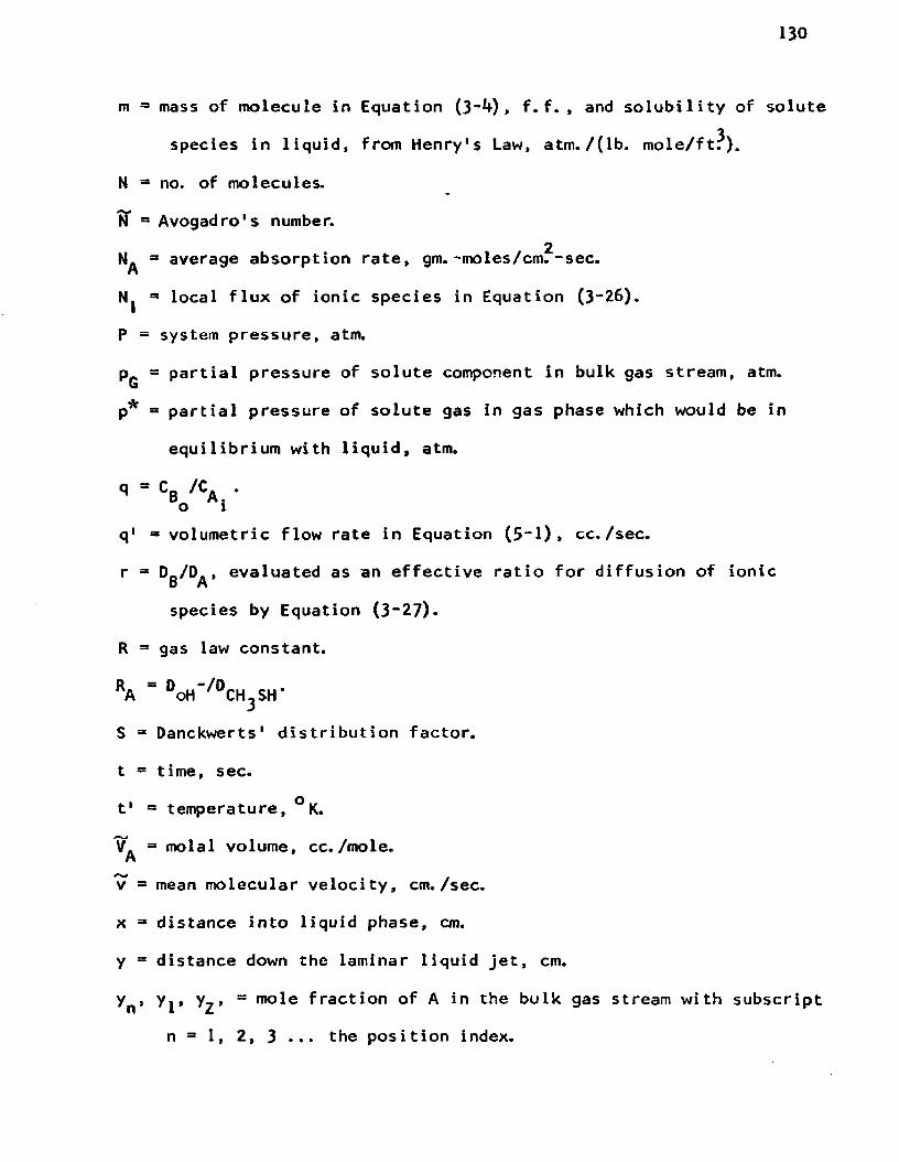
130
m = mass of molecule in Equation (3"*0 > f. f. , and solubility of solute
species in liquid, from Henry's Law, atm./(lb. mole/ft?).
N = no. of molecules.
TT = Avogadro's number.2N. ** average absorption rate, gm. -moles/cm. -sec.n
Nj = local flux of ionic species in Equation (3“2.6).
P = system pressure, atm.
p = partial pressure of solute component in bulk gas stream, atm.Gp* = partial pressure of solute gas in gas phase which would be in
equilibrium with liquid, atm.
q = C /C .o i
q' = volumetric flow rate in Equation (5“ 1)» cc./sec.
r = D-/D., evaluated as an effective ratio for diffusion of ionic 0 Mspecies by Equation (3~27).
R = gas law constant.
RA " d o h “/0c h 3 s h ’
S = Danckwerts* distribution factor.
t = time, sec.
t 1 = temperature, °K.
V. =* molal volume, cc. /mole.Av = mean molecular velocity, cm./sec.
x = distance into liquid phase, cm.
y = distance down the laminar liquid jet, cm.
yn » y^, y^» ° mole fraction of A in the bulk gas stream with subscript
n = 1, 2, 3 ... the position index.

131
Z| 3 valence of species 1
J W ' »
Greek Letters
a 3 constants defined where used.
3 constant defined where used.
y 3 constant defined where used.
3 kL/k° .
$ 3 asymptotic value of $ at large values of 0 (ord0_ 3 association parameter used in diffusion correlation by Wilke.D\ 3 variable substituted in solution of Equation (5“*0-
X7} 3 dimensionless length variable 3 — ■ —
*0 3 K_ C_ t, dimensionless time of contact,
oY 3 Xl first derivative of x with respect to 7J .
j(i 3 viscosity, centipoise.
K 3 Boltzman's constant.
X L 3 mean free path. *
3 collision integral.
a*„ 3 collision diameter.ABcr = parameter in parametric equations.

SELECTEO BIBLIOGRAPHY
1. Bird, R. B. , Stewart, W. E. , and Lightfoot, E. N. TransportPhenomena. New York: John Wiley and Sons, Inc. , I960.
2. Brian, P. L. T. “Gas Absorption Accompanied by an IrreversibleReaction of General Order,11 A. I. Ch. E. Journal, X (1964)p. 5«
3. Brian, P. L. T. , Baddour, R. F. , and Matiatos, D. C. "An IonicPenetration Theory for Mass Transfer with Chemical Reaction,"A. I. Ch. E. Journal, X (1964), p. 727-
4. Brian, P. L. T. , Hurley, J. F. , and Hasseltine, E. H. "Penetration Theory for Gas Absorption Accompanied by a Second Order Chemical Reaction," A.I.Ch.E. Journal, VII (1961), p. 227.
5. Clarke, J. K. A. "Kinetics of Absorption of Carbon Dioxide inMonoethanolamine Solutions at Short Contact Times,"Industrial and Engineerinq Chemistry - Fundamentals,III (1964), p. 211.
6. Colburn, A. P. "The Simplified Calculation of DiffusionalProcesses," Transactions of the American Institute of Chemical Engineers, XXXV (1939), p. 211.
7- Danckwerts, P. V. "Gas Absorption Accompanied by Chemical Reaction," A. I. Ch. E. Journal, I (1955), p. 456.
8. _________. "Significance of Liquid Film Coefficients in GasAbsorption," 1ndustrial and Engineering Chemistry, XLI11 (1951), p. 1460.
9. _________. "Absorption by Simultaneous Diffusion and ChemicalReaction," T ransact ions of the Faraday Society. XLV1 (1950), p. 300.
10. Daniels, F. and Alberty, R. A- Physical Chemistry. New York:John Wiley and Sons, Inc. , 1955- p- 650.
11. Davidson, J. F. and Cullen, E. J. "The Determination ofDiffusion Coefficients for Sparingly Soluble Gases in Liquids," T ransactions of the Insti tut ion of Chemical Engineers (London), XXXV (1957), p* 5 H
132
133
12. Eigen, M. “Methods for Investigation of Ionic Reactions inAqueous Solutions With Half-Times as Short as 10”° Sec.," Discussions of the Faraday Society. XVII (195*0, P* 194.
13. Hasseltine, E. H. and Hurley, J. F. “Solutions of Phase ChemicalReaction," Unpublished S.B. thesis, Massachusetts Institute of Technology, 1951.
14. Hatta, S. Technical Reports. Tohoku Imperial University, X(1932), p. 119, from Sherwood and Pigford (1952).
15. Higbie, R. "The Rate of Absorption of a Pure Gas into a StillLiquid During Short Periods of Exposure," A. I. Ch. E. Journal, XXXI (1935), p. 365.
16. Himmelblau, D. M. “Diffusion of Dissolved Gases in Liquids,"Chemical Reviews. LXIV (196**) , pp. 527*550.
17. Hi rschfelder, J. 0., Curtiss, C. F. , and Bird, R. B. MolecularTheory of Gases and Liquids. New York; John Wiley andSons, Inc., 1954.
18. Huang, C. and Kuo, C. "General Mathematical Model for MassTransfer Accompanied by Chemical Reaction," A.1■Ch.E.Journal, IX (1963), p. 161..
19. Hughmark, G. A. "Point Efficiencies for Tray Distillations,"Chemical Engineering Progress, LXI (1964), p. 97.
20. International Critical Tables. Vol. 3- New York: McGraw-HillInc. , 1928. p. 259.
21. Jensen, G. A. Final Report on Absorption of Odor ProducingSulfur Compounds, to National Council for Stream Improvement, December 31, 1964.
22. Jost, W. Pi ffusion in Sol ids, Li quids, and Gases. New York:Academic Press, Inc., i960. p. 439*
23. King, R. W. and Fielding, J. C. "A Graphical Design Method forNitric Acid Absorption Towers," Transactions of the Insti- tution of Chemical Engineers (London), XXXVII I (196oJ^ p. 71.
24. Korn, G. A. and Korn, T. M. Mathematical Handbook for Scientistand Engineers. New York: McGraw-Hill, Inc., 1961. p. 899-
25. Lapidus, L. Fundamentals of Mass Transfer Processes, Part 1, ofSeparation Processes. Edited by R. F. Chapman. New York: Rheinhold Publishing Co., 1361- p. 2.

13**
26. Levenspiel, 0. A. Chemical Reaction Engineering. New York:John Wiley and Sons, Inc. , 1962. p. 532.
27. Lewis, W. K. and Whitman, W. G. "Principles of Gas Absorption,"1ndustrial and Engineering Chemistry, XVI (1924), p. 1215.
28. Nernst, W. Zeit. Phys. Chem. , (Leipzig), II (1888), p. 613.
29* Peaceman, D. W. "Liquid Side Resistance in Gas Absorption Withand Without Chemical Reaction," Unpublished Sc.D. thesis, Massachusetts Institute of Technology, 1951.
30. Perry, J. H. Chemical Engineers' Handbook. 4th ed. New York:McGraw-Hill, Inc., 1963. pp. 14-19.
31. Planck, M. Ann. Physik, XXXIX (1890), p. 161.
32. Rabe, A. E. and Harris, J. F. "Vapor Liquid Equilibrium Datafor the Binary System, Sulfur Dioxide and Water," Journal of Chemical and Engineering Data, V I M (1963), p. 3*
33- Raimondi, P. and Toor, H. L. "Interfacial Resistance in GasAbsorption," A. I. Ch. E. Journal, V (1959), P- 86.
34. Rehm, T. R. Unpublished Master's thesis, University ofWashington, i960.
35* President's Science Advisory Committee. Restoring the Qualityof Our Environment. Report of the Environmental Pollution Panel. November, 1965-
36. Schoenfeld, F. "Ueber den Absorptions Coefficient en den Schwefligen,Saure, des Chors und Schwefelwasserstaff," Annalen der Chemie Justus Liebigs, XCV (1855), pp. 1“23-
37- Scrivens, L. E. and Pigford, R. L. "On Phase Equilibrium at theGas-Liquid Interface During Absorption," IV (1958), p. 439.
38. Secor, R. M. and Southworth, R. W. "Absorption With an InfinitelyRapid Chemical Reaction in Packed Towers," A.I.Ch.E. Journal.V M (1961), p. 705.
39. Sherwood, T. K. and Wei, J. C. "Ion Diffusion in Mass TransferBetween Phases," A. I. Ch. E. Journal. I (1955), p. 522.
40. Sherwood, T. K. and Hollaway, F. A. L. "Performance of PackedTowers - Liquid Film Data for Several Packings," Transact ions of the American Institute of Chemical Engineers,XXXVI (1940).
41. Sherwood, R. K. and Pigford, R. L. Absorption and Extraction.2nd ed. New York: McGraw-Hill, Inc., 1952. pp. 317~339-
135
1*2. Sherwood, T. K. and Ryan, J. M. "Mass Transfer to a TurbulentFluid With and Without Chemical Reaction," ChemicalEngineering Science. XI (1959), p. 81.
43. Spalding, C. W. "Reaction Kinetics in the Absorption ofChlorine into Aqueous Media," A.I.Ch.E. Journal, VIII (1962), p. 685.
1*1*. Teller, A. J. "Absorption with Chemical Reaction," ChemicalEngineering. July 11, 1961, p. 111.
1*5. Trambouze, P., Trambouze, M. T. , and Piret, E. L. "ChemicalReaction in Two-Phase Systems," A.I.Ch.E. Journal. VII(1961), p. 138.
1*6. Toor, H. L. and Marchello, J. M. "Film-Penetration Model forMass and Heat Transfer," A. I. Ch. E. Journal, IV (1958), p. 97.
1*7. Toor, H. L. and Chiang, S. H. "Diffusion-Controlled Reactions,"A. I. Ch. E. Journal, V (1959). p. 339.
1*8. Tyrell, H. J. V. D if fusion and Heat Flow in Ligu ids. London:Butterworths, Inc., 1961. p. vii.
1*9. Vinograd, J. R. and McBain, J. W. "Diffusion of Electrolytesand of the Ions in Their Mixtures," Journal of the AmericanChemical Society, LXI1I (1941). p. 2008.
50. Vivian, J. E. and King, C. J. Absorption and Distillation. Ch. 9,Vol. 1 of Modern Chemical Engineering. Edited by A. Acrivos. New York: Reinhold, Inc. , I960.
51. Whitman, W. G. "The Two Film Theory of Gas Absorption," Chemicaland Metallurgical Engineering, XXXIX (1923), p. 146.
52. Wilke, C. R. "Estimation of Liquid Diffusion Coefficients,"Chemical Engineering P rogress. XLV (1949), PP- 218-224.
53. Yoshida, F. and Koyanagi, T. "Mass Transfer and Effective Interfacial Areas in Packed Columns," A.I•Ch.E. Journal, III(1962), p. 309-

APPENDICES

APPENDIX A
CALCULATION OF IONIC DIFFUSIVITIES
In the case of gas absorption with simultaneous ionic reactions,
it is the diffusion of the ionic specie that is important, and allowance
must be made for the fact that the individual ions in the presence of
other ions may diffuse at rates which are different from those of their
original molecular specie pair. Sherwood and Wei^ showed how the results2of Vinograd and McBain could be extended to irreversible reactions by
estimating the concentration gradients. The Hatta film theory may be
used to graphically depict the diffusion of methyl mercaptan into the
aqueous sodium hydroxide solution, followed by a reaction to form the
salt (see Figure 2).
CH3SH(gj Z CH3SH(A) (A.A-1)
CHjSH^j Z CH3S_ + H+ (A.A-2)
NaOH(A) - N a ^ + O H ^ (A.A-3)
ch3shU ) + Na(i) + 0 H (JC) CH3S U ) + Na(jI) + H0H(j&) (a*a-4)
T̂. K. Sherwood and J. C. Wei, “ Ion Diffusion in Mass Transfer Between Phases," A. I. Ch. E. Journal, I (1955), p. 522.
2J, R. Vinograd and J. W. McBain, "Diffusion of Electrolytes and of the Ions in Their Mixtures," Journal of the American Chemical Society, LXII (1961), p. 2008.
137

138
Vinograd and McBain, following the Nernst theory, wrote diffusion
equations for each ion. The authors imposed the conditions of elec
trical neutrality at each point and linear concentration gradients.
The following equation was derived for the diffusion of cations:
ox £ U 6 /n - £ U_G_/n_n+N+ - - p- — <G+ - n+C+ £ u+C+ + £ U+C_ * (A.A-5)
Here N. is the ion flux of a particular cation having a valence n ,T *
concentration C., and mobility U ; G. is the concentration gradientT T T
dC+/dx of this cation in the direction of diffusion, and the minus
signs refer to the anions. The derivation is subjected to the
limitation that the activity coefficients and collision effects are
ignored, as are the effects of ion pairs or ionic complexes. All of
these approximations are well within the accuracy of the analysis of
mass transfer effect.
Sherwood and Ryan^ have given the solution in closed form as.
2 R.eff (A. A “6)
where Rft - D0H“/DCH3sH
^T. K. Sherwood and J. M. Ryan, "Mass Transfer to a Turbulent Fluid With and Without Chemical Reaction," Chemica1 Engineering Science, XI (1959), p. 81.

139
Rp " DCH3 s "/DCH3SH
B - [OH*] /[Na+ ] o o
The values of these diffusion coefficients were all known except the
diffusion of the mercaptide ion CH3S . Other investigators have
reported values for the diffusion coefficient of the acetate ion,
which is approximately the same size and has the same charge as the
mercaptide ion. As the nearest approximation, the two were ratioed
according the molecular weight and the value used for the diffusion
of the mercaptide ion. The values of the variables in Equation (A.A-6)
are
d c h 3s - ■ *-° OT?/da* ra “ do h ‘/d c h 3s h ■
Cru cu “ 1* °3 cm?/day R » Dru e-/Dru cu - .97'CHjSH ' — ' ' p CHjS ' CHjSH
20 - * k. 51* cm. /dayOH
B - 1
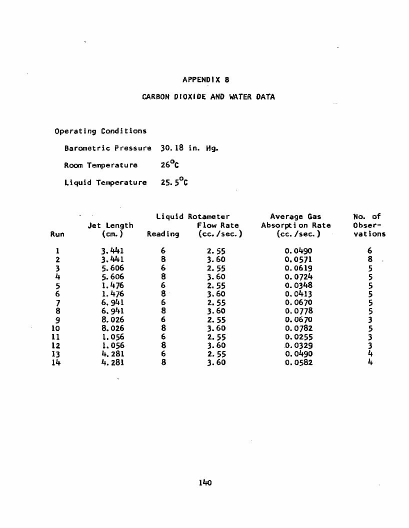
APPENDIX B
CARBON DIOXIDE AND WATER DATA
Operating Conditions
Barometric Pressure 30. 18 in. Hg.
Room Temperature 26°C
Liquid Temperature 25.5 C
- Liquid Rotameter Average GasJet Length Flow Rate Absorption Rate
Run (cm.) Read ing (cc. /sec.) (cc. /sec.)
1 3. ififl 6 2. 55 0.04902 3.441 8 3.60 0.05713 5.606 6 2. 55 0.0619it 5.606 8 3.60 0. 07245 1.476 6 2.55 0.03486 1.476 8 3.60 0. 04137 6.941 6 2. 55 0. 06708 6.941 8 3.60 0.07789 8. 026 6 2. 55 0. 067010 8. 026 8 3.60 0.078211 1.056 6 2. 55 0. 025512 1.056 8 3.60 0.032913 4. 281 6 2. 55 0.0490lif 4. 281 8 3.60 0.0582
No. of Observations
685555553533ifif
lifO

APPENDIX B (Continued)
SULFUR DIOXIDE AND WATER DATA
Operating Conditions
Barometric Pressure 30.05 in. Hg.
Room Temperature 26. 5°C
Liquid Temperature 25°C
Liquid Rotameter Average Gas No. ofJet Length Flow Rate Absorption Rate Obser
Run (cm. ) Reading (cc. /sec.) (cc./sec.) vations
1 8.33 5 1.92 2. 1 52 8.33 6 2. 55 2.06 53 7. 736 6 2. 55 2.08 54 7. 736 6 2. 55 2.31 35 5- 730 6 2. 55 2.00 56 7. 736 8 3.60 2. 62 47 7. 736 8 3.60 2.44 48 4.94 6 2. 55 1.65 39 4.94 8 3.60 2.04 510 4. 77 8 3.60 1.85 311 1.416 8 3.60 1.11 312 • 95 6 2. 55 0.763 513 .95 8 3.60 0.91 4
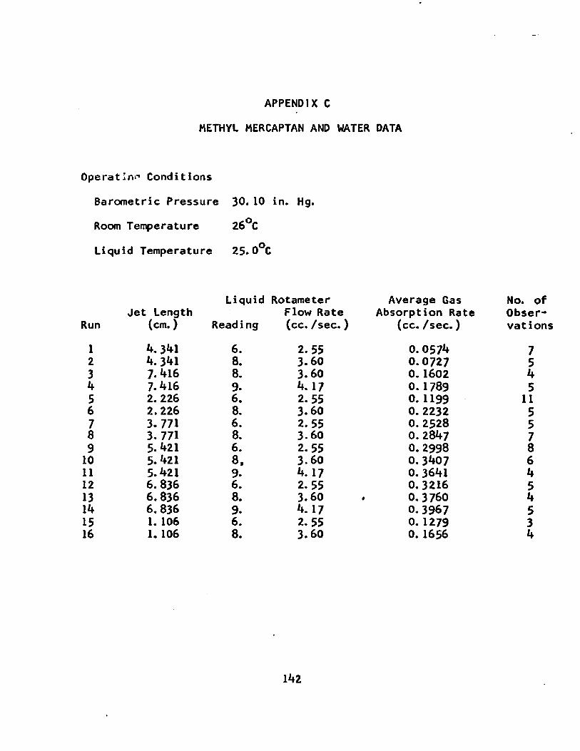
APPENDIX C
METHYL MERCAPTAN AND WATER DATA
Operating Conditions
Barometric Pressure 30. 10 in. Hg.
Room Temperature 26°C
Liquid Temperature 25.0°C
Liquid Rotameter Average Gas No. ofJet Length Flow Rate Absorption Rate Obser
Run (cm.) Reading (cc. /sec.) (cc. /sec.) vations
1 4.341 6. 2. 55 0. 0574 72 k. 341 8. 3.60 0.0727 53 7.416 8. 3.60 0. 1602 44 7.416 9. 4.17 0.1789 55 2. 226 6. 2. 55 0.1199 116 2.226 8. 3.60 0.2232 57 3. 771 6. 2. 55 0.2528 58 3. 771 8. 3-60 0. 2847 79 5. 421 6. 2. 55 0.2998 810 5.421 8, 3.60 0. 3407 611 5.421 9. 4.17 0. 3641 412 6. 836 6. 2. 55 0. 3216 513 6.836 8. 3.60 0.3760 414 6. 836 9. 4. 17 0. 3967 515 1. 106 6. 2. 55 0.1279 316 1. 106 8. 3.60 0. 1656 4
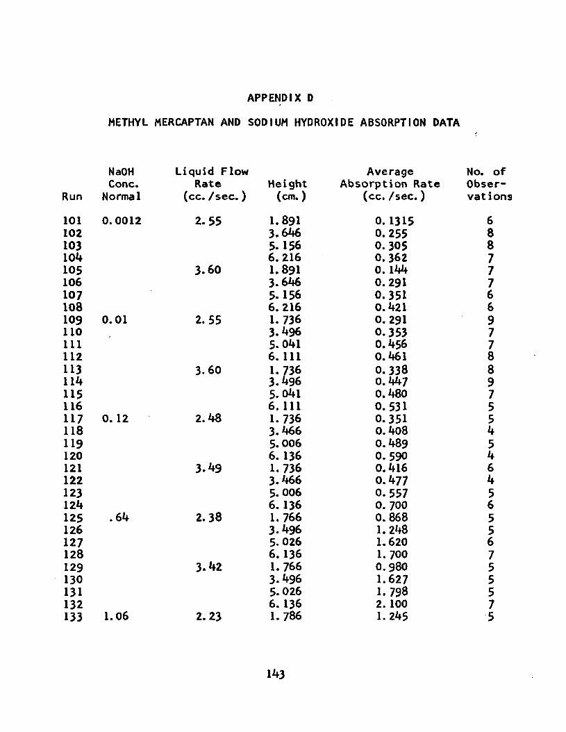
APPENDIX D
METHYL MERCAPTAN AND SODIUM HYDROXIDE ABSORPTION DATA
NaOH Liquid Flow Average No. oCone. Rate Height Absorption Rate Obser
Run Normal (cc. /sec.) (cm.) (cc. /sec.) vatio
101 0.0012 2. 55 1.891 0. 1315 6102 3.646 0. 255 8103 5. 156 0. 305 8104 6. 216 0. 362 7105 3.60 1.891 0. 144 7106 3.646 0. 291 7107 5.156 0.351 6108 6.216 0.421 6109 0.01 2.55 1.736 0. 291 9110 3.496 0.353 7111 5. 041 0.456 7112 6. Ill 0.461 8113 3.60 1.736 0, 338 8114 3.496 0.447 9115 5.041 0.480 7116 6. Ill 0. 531 5117 0. 12 2.48 1.736 0.351 5118 3.466 0.408 4119 5.006 0.489 5120 6. 136 0. 590 4121 3.49 1. 736 0.416 6122 3.466 0.477 4123 5. 006 0. 557 5124 6.136 0. 700 6125 .64 2. 38 1. 766 0. 868 5126 3.496 1.248 5127 5. 026 1.620 6128 6. 136 1. 700 7129 3.42 1. 766 0.980 5130 3-496 1.627 5131 5. 026 1.798 5132 6. 136 2. 100 7133 1.06 2. 23 1. 786 1.245 5
143

Run
134135136137138139140141142143144145146147148
METHYL
NaOHCone.
Normal
2. 54
144
APPENDIX D (Continued)
MERCAPTAN AND SODIUM HYDROXIDE ABSORPTION DATA
Liquid Flow Average No. oiRate Height Absorption Rate Obser
(cc. /sec. ) (cm. ) (cc. /sec.) vat ioi
3.461 1.280 55. 006 2. 154 46. Ill 2.320 5
3.24 1. 786 1.462 53.461 1. 500 45.006 2. 57 36. Ill 2. 60 5
1.7 0. 786 1. 154 51. 711 2. 110 73.456 3. 200 45.006 3.930 8
2. 58 0.786 1.482 51. 711 2. 560 53.456 3. 730 65.006 4. 180 7
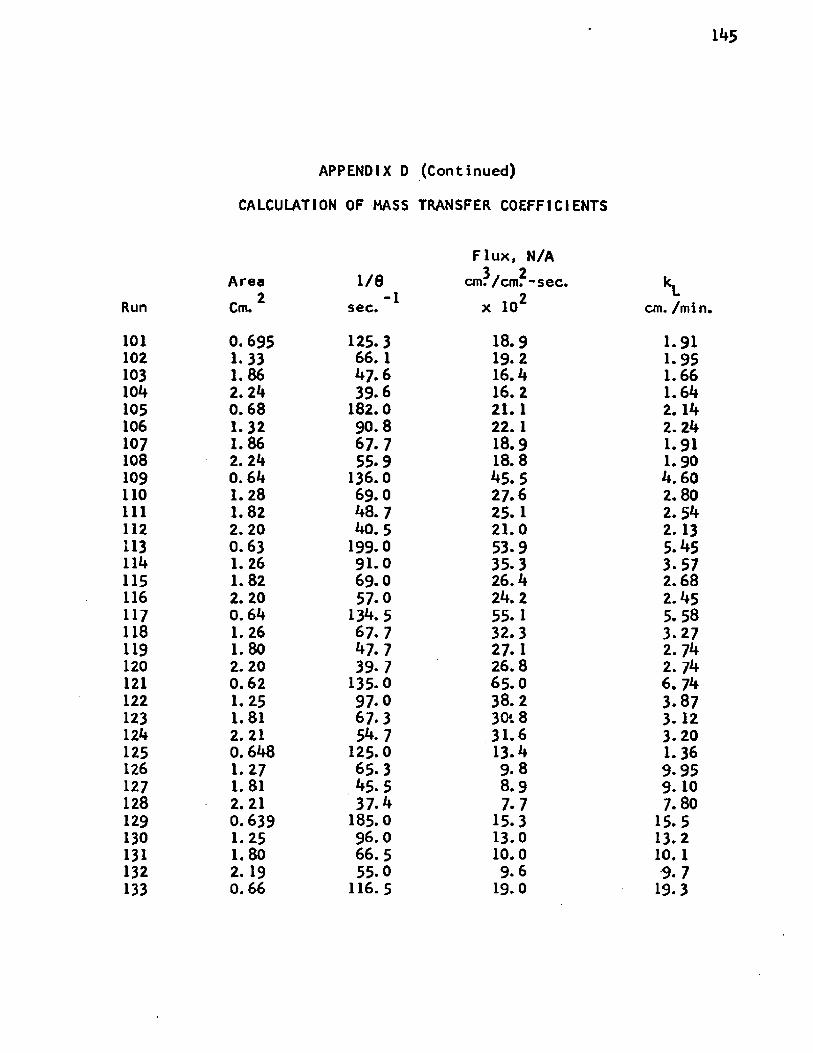
145
APPENDIX D (Continued)
CALCULATION OF MASS TRANSFER COEFFICIENTS
Flux, N/A
RunArea_ 2 Cm.
1/0-1sec.
3 2 cm. /cm. -sec.2x 10*
“lcm. /min
101 0.695 125.3 18.9 1.91102 1.33 66. 1 19.2 1.95103 1.86 47.6 16.4 1.66104 2.24 39.6 16.2 1.64105 0.68 182.0 21. 1 2.14106 1.32 90.8 22. 1 2. 24107 1.86 67.7 18.9 1.91108 2. 24 55.9 18.8 1.90109 0.64 136.0 45.5 4. 60110 1.28 69.0 27.6 2.80111 1.82 48. 7 25.1 2. 54112 2.20 40.5 21.0 2.13113 0.63 199.0 53-9 5.45114 1.26 91.0 35.3 3.57115 1.82 69.0 26.4 2.68116 2. 20 57.0 24.2 2.45117 0.64 134.5 55.1 5. 58118 1. 26 67.7 32.3 3.27119 1. 80 47.7 27.1 2. 74120 2. 20 39-7 26.8 2. 74121 0.62 135.0 65.0 6. 74122 1. 25 97-0 38.2 3.87123 1.81 67.3 30*. 8 3-12124 2.21 54.7 31.6 3.20125 0.648 125.0 13.4 1.36126 1.27 65-3 9.8 9.95127 1.81 45.5 8.9 9. 10128 2.21 37.4 7.7 7. 80129 0.639 185.0 15.3 15.5130 1.25 96.0 13.0 13.2131 1.80 66. 5 10.0 10.1132 2. 19 55.0 9.6 9. 7133 0.66 116. 5 19.0 19.3

Run
135136137139140141142143145146147148
APPENDIX D (Continued)
CALCULATION OF MASS TRANSFER COEFFICIENTS
Flux, N/AArea 1/0 3/ 2cm. /cm. ■Cm- 2 -1sec. x 102
1.81 43.3 11.92. 20 35.3 10.60.64 174.0 22.61.79 63.3 14.32. 19 52.0 11. 80. 292 92.0 33.50. 630 46. 5 25.41. 26 32. 5 21. 70. 292 300.0 50.70.630 141.0 40.61. 26 70. 5 29.61.81 57.4 23.0

APPENDIX D (Continued)
E F F E C T O F H Y D R O X Y L C O N C E N T R A T I O N ON A B S O R P T I O N C O E F F I C I E N T
q .0049 0.041 0. 49 2. 61 4.33 10. 37
k°k l kL $ k L $ kL $ kL $ k L $ kL $
1.5 1.7 1.13 2.3 1.53 2.8 1.86 8.7 5.8 12.1 8.06 25.0 16.71.7 1.9 1.12 2.65 1.56 3.2 1.88 9.6 5.65 13.5 7.95 27.5 16.21.9 .2.15 1.13 3.0 1.58 3.7 1.95 10.6 5.58 15.0 7.9 30.0 15.82.1 2.35 1.12 3.35 1.59 4.1 1.95 11.7 5.57 16.6 7.9 33.0 15.73.0 3.4 1.13 5.10 1.70 6.2 2.07 16.2 5.4 23.0 7.67 44.0 14.7
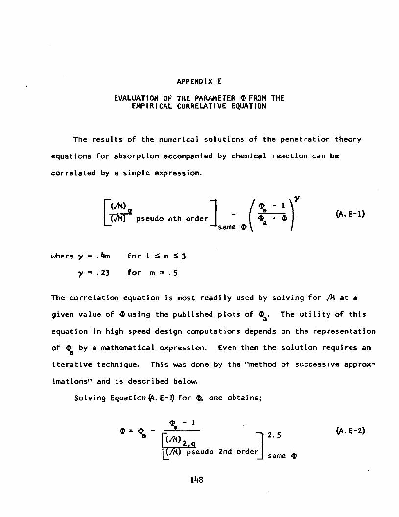
APPENDIX E
EVALUATION OF THE PARAMETER $ FROM THE EMPIRICAL CORRELATIVE EQUATION
The results of the numerical solutions of the penetration theory
equations for absorption accompanied by chemical reaction can be
correlated by a simple expression.
where y ~ . **m for 1 £ m ^ 3
y * . 23 for m *» . 5
The correlation equation is most readily used by solving for /M at a
given value of $ using the published plots of $ . The utility of this
equation in high speed design computations depends on the representation
of by a mathematical expression. Even then the solution requires an 3iterative technique. This was done by the "method of successive approx
imations" and is described below.
Solving Equation E-l) for one obtains;
PiT pseudo nth order (A.E-1)
I '2iS(/M) pseudo 2nd order2.5
same
(A.E-2)
lk8

for a second order chemical reaction.
The analytical equation found to represent $ accurately enoughd(with a maximum error of 1%) is, .
$ - ,/M [1 + erf y ® + i exp (^jr) (A. E-3)
It is the exact solution for a pseudo first order and used in this case
because the order of the reaction in pseudo cases does not affect the
solution. A maximum deviation of 3% between zero order and third order
as accurate as picking values from the small plots which have been
published.
Solving Equation explicitly of M (or ,/M) is not practical,
therefore the parameter is expressed as a function of itself for the
iterative method of solution as follows,
desiring a value of 4 . Entering Equation (ft. E-2) with values of
(>/M), 3* =* 1 + /rq, and an estimate of (,/M) pseudo 2nd order, aH *value of $ is obtained. This <b and the first estimate of M (,/Mj) is used to get a new estimate of M C/M^j) from Equation (ft. E-4). The
late value of M is used again in Equation (fr. E-2) to get another
$ - ff/8yM. erf
(A. E-4)
The calculation procedure starts with having a value of (,/M)

150
and Equation (A.E-*0 to get a late value of M This is used
successively until a convergence test on the value of ,/M is met, as
shown in the following FORTRAN program. The two equations could be
combined to eliminate but since $ is a desired result, there was
no need to destroy its identity and have to recalculate it. Table
A.E-l shows how test runs proved the validity of the method which was
used as a subroutine in a larger program.
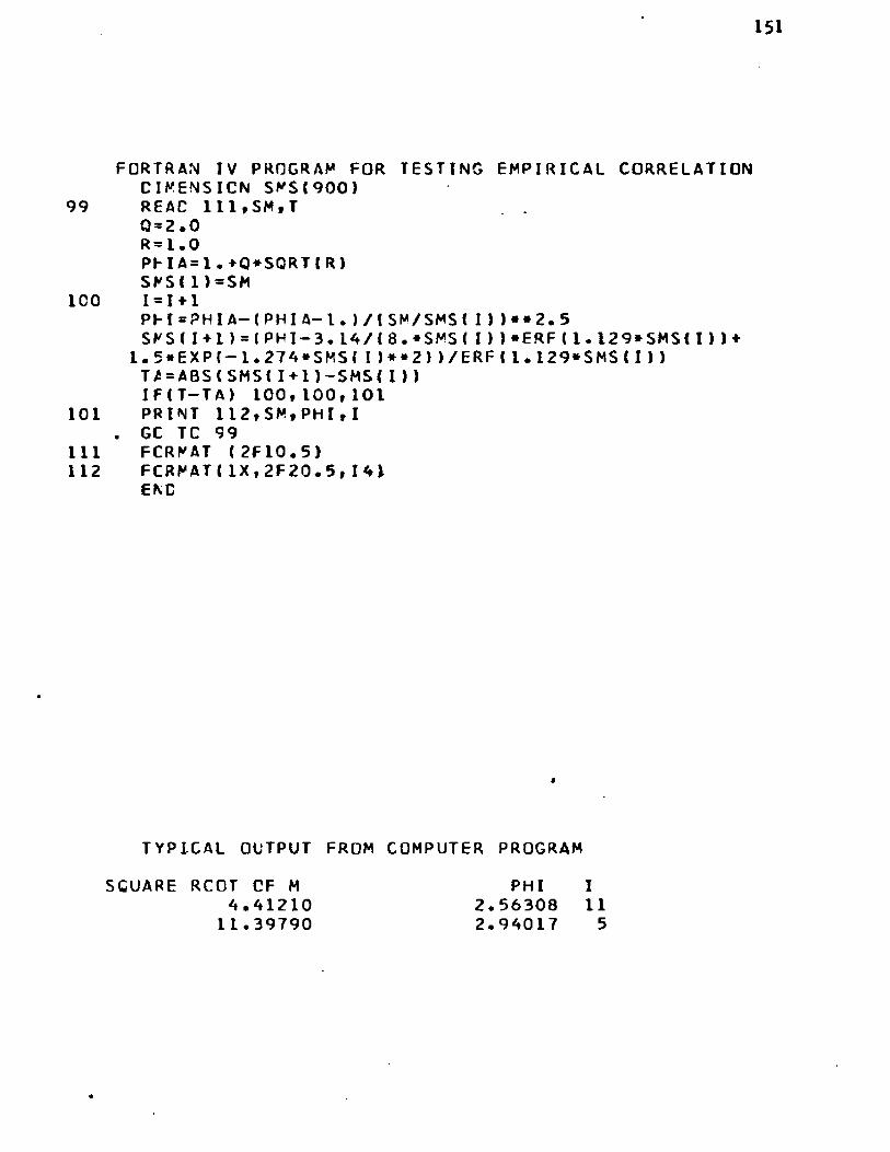
151
F O R T R A N IV P R O G R A M F O R T E S T I N G E M P I R I C A L C O R R E L A T I O N D I M E N S I O N S M S I 9 0 0 )
99 READ l l l , S M , T 0 = 2.0 R= i .0P F I A = 1 • + Q + S G R T I R )S M S (1) =S M
ICO 1=1+1PFI = P H I A — (PHI A— I . ) / ( S M / S M S ( I ) )** 2.5 S M S ( I + I ) = ( P H I - 3 . 1 A / (8 . + S M S ( I ))+ E R F ( 1 . 1 2 9 * S M S ( I ))♦
1 . 5 * E X P ( — 1 . 2 7 4 * S M S ( I ) * * 2 ) ) / E R F ( 1 . 1 2 9 * S M S ( I )) T £ = A B S ( S M S ( I + 1I — SMS ( I ) )I F ( T - T A ) 1 0 0 , 1 0 0 , 1 0 1
101 P R INT 1 1 2 , S M ,PH 1,1 . GC TC 99
111 F C R M A T (2F10.5)112 F C R M A T ( 1 X , 2 F 2 0 . 5 , 141
END
T Y P I C A L O U T P U T F R O M C O M P U T E R P R O G R A M
SCUARE RCOT CF M 4.4121011.39790
PHI I 2.56308 112.94017 5

152
Table A.E-l
r » 1 q ■ 2. 0
No. of T rials
665
14
Convergence test on /M was ± 0.001
Convergence test on was ± 0.0001
* No. of<A\ v Trials
100.000 2.99972 5 2.9997250.0000 2.99843 5 2.9984311.3979 2.94017 5 2.940174.4121 2.56308 II 2.56334
T rue Value
2. 997 2. 9984 2. 9402 2.5635
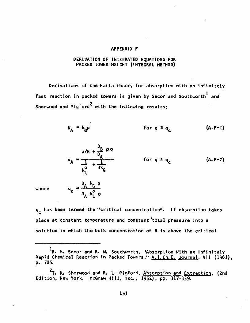
APPENOtX F
DERIVATION OF INTEGRATED EQUATIONS FOR PACKED TOWER HEIGHT (INTEGRAL METHOD)
Derivations of the Hatta theory for absorption with an infinitely
fast reaction in packed towers is given by Secor and Southworth^ and2Sherwood and Pigford with the following results:
NA - kQp f o r q * q c (A.F-1)
P/H°Ah i --------- for q S q c (A.F-2)A 1 , 1
k£ HkG
DA kG pwhere q„ “ ----- —c _ . o°A "l *
qc has been termed the "critical concentration". If absorption takes
place at constant temperature and constant ‘total pressure into a
solution in which the bulk concentration of B is above the critical
*R. H. Secor and R. W. Southworth, "Absorption With an Infinitely Rapid Chemical Reaction in Packed Towers," A.I.Ch.E. Journal, VII (1961), p. 705.
2T. K. Sherwood and R. L. Pigford, Absorption and Extraction, (2nd Edition; New York: McGraw-Hill, Inc., 1952), pp. 3 17~339-
153
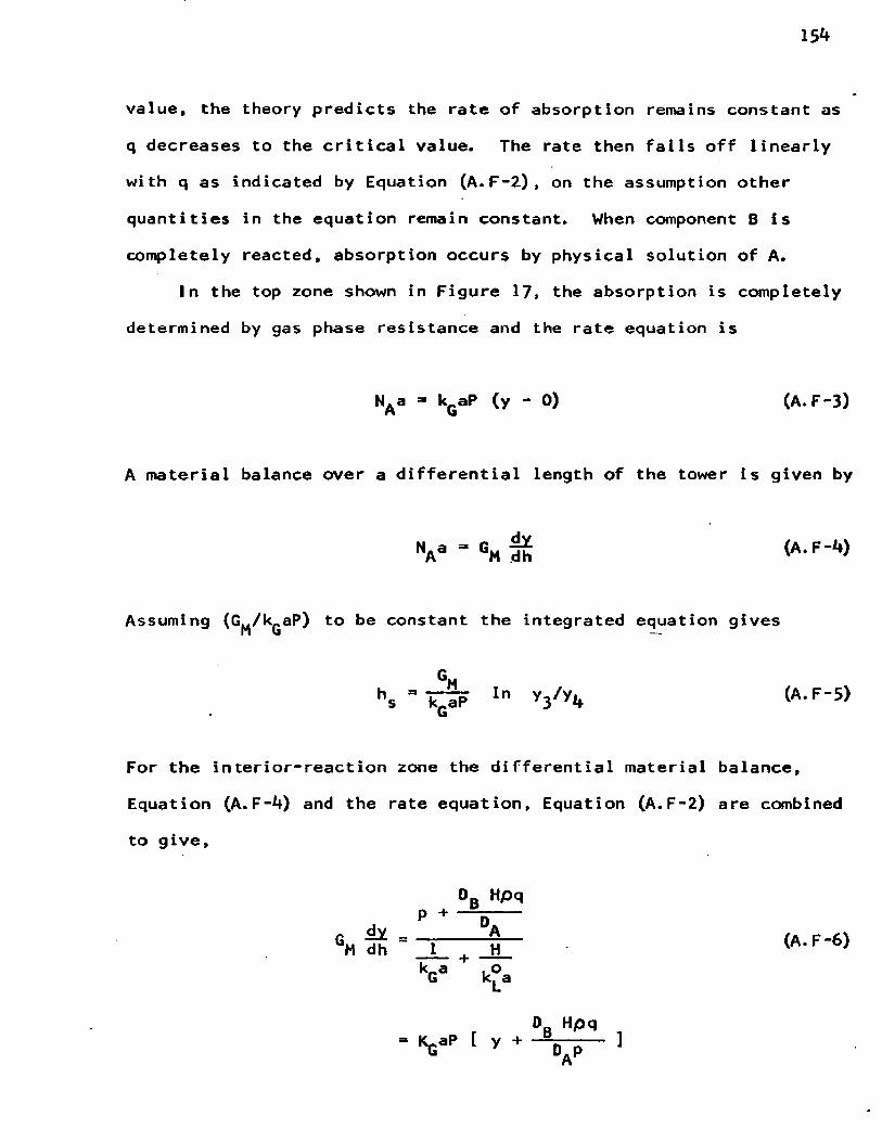
154
value, the theory predicts the rate of absorption remains constant as
q decreases to the critical value. The rate then falls off linearly
with q as indicated by Equation (A. F-2) , on the assumption other
quantities in the equation remain constant. When component B is
completely reacted, absorption occurs by physical solution of A.
In the top zone shown in Figure 17. the absorption is completely
determined by gas phase resistance and the rate equation is
NA a - kQaP (y - 0) (A.F-3)
A material balance over a differential length of the tower is given by
Assuming (G^/k^aP) to be constant the integrated equation gives
h, - T c S p ln y3/y4 (A-F '5)
For the interior-reaction zone the differential material balance,
Equation (A.F-4) and the rate equation, Equation (A.F-2) are combined
to give,
0B Hpqp + ---
6M dh = ~ ! H (A.F-6)k_a . o G k^a
0R HpqV [ y + - \ r - 1

155
It is convenient to define the Henry1s law constant in terms o
fractions as m =* pH/P, which gives
GM dh = KGaP + D. *
A material balance over a portion of the tower gives
q - qc - ̂ (v - y3)
Substituting Equation (A.F-8) into (A.F-7) yields
dh gm u S. “a , y da
+ — “— - v 1 L D y 3 J M A 5
Equation (A. F-9) is of the form
, KraPi " l “ « * y + &n
mole
(A. F-7)
(A. F-8)
(A. F-9)
(A.F-10)
where a and J3 are constants. Separating the variables and integrating,
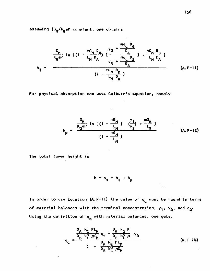
assuming (G^/k^aP constant, one obtains
mqc °BM i. r n "MM r ~ °A n ^ '""H "SG„ mG„ D„ y2 + D. mG„ D
TT^p in [ (1 - 1- V ^ ) [ --------- — V ] + - r ^ ]G Si A qc B M °A
3 D.hl " ------------------------- mG~ 0B ----------------- (A*F-U >n P
‘H °A
For physical absorption one uses Colburn's equation, namely
6m mGM Yij j p » " « « - - £ >
h =■ — ------------- -jjH----— -------=— (A. F-12)P mGM< 1 * ^ )
The total tower height is
h * h + h. + h s I p
In order to use Equation (A.F-ll) the value of q must be found in termscof material balances with the terminal concentration, y^, y^, and q^.
Using the definition of q with material balances, one gets,c
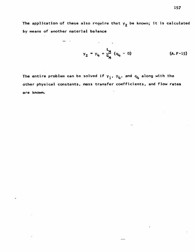
157
The application of these also require that he known; it is calculated
by means of another material balance
y 2 " ( q J* ' 0 ) (A - F - 1 S )H
The entire problem can be solved if y^, y^, and q^ along with the
other physical constants, mass transfer coefficients, and flow rates
a re known.

APPENDIX G
STATEMENT LIST OF COMPUTER PROGRAM FOR PACKED ABSORBER CALCULATIONS BY DIFFERENTIAL METHOD
158

159
*JC8 J.E.L. R E A C T O R M O D E LD I M E N S I O N Y< 5 0 0 ) , C K G ( 5 0 0 > , 0 ( 5 0 0 > , C t 500) ,S M ^ t S O O ) ,
1 E K G (500)CALL F P T R A P C - 3 )
1000 R E A D 1 3 , X K G , X K L * D A , D B , X K F , X M R E A D 1 * , G , X L , A E ,A , B 8 ,P , N ,T
1 R E A D 18* OP t SMT B = 08X K L O = X K L / A E * ( 3 0 • 5 / 3 6 0 0 • )R = S Q R T (DB/OA)XN = NP U N C H 501
501 F C R M A T (6 X , 1 1 H G A S P H A S E K , 3 X , 1 2 H L I Q . PHA S E K,4X,1 1 0 H S O L U B I L I T Y )PUNCH 19* XKG tXKL * XM
19 F C R M A T (3F 15« 2)55 P U NCH 500500 F C R M A T l * X , 6 H H E I G H T *2X» 8 H L I Q C O N C » 2X » 1 6 H 0 U T L E T GA S CONC.
1 2 X * 1 7 H F R A C T I 0 N A B S O R B E D )1 1 7 H F R A C T I C N A B S O R B E D )
5 H = (A— B )/X NK C - 0DC 88 J = 1 , N X J = JY< J)=B + X J * H Q {J )= Q P — G / X L * (Y < J ) — B )
C TEST FOR Z E R O R E A C T A N T C O N C E N T R A T I O N IF(OtJ)) 7 1 * * , A
71 K O = K O + 1 IF(KO-l) 7 2 * 7 2 , 7 3
72 X C = G / X L * { A — Y ( J ) )73 YS=i X O - G / X L M A - Y (J ) ) ) * X M * 3 . 4 6 _C C A L C U L A T E C O E F F I C I E N T FOR P H Y S I C A L A B S O R P T I O N
C K G < J ) = 1 . / ( 1 . / X K G + X M / X K L )C K G t J ) = C K G ( J ) * ( Y ( J ) - Y S ) / Y ( J )GC TO 88
C C A L C U L A T E FOR C H E M I C A L A B S O R P T I O N * K = 0
C STA RT I T E R A T I V E P R O C E D U R E FOR I N t E R F A C I A L C O N C C A L C U L A T I O N C < 1 )=Y< J ) / ( X M * 3 . 4 6 )
2 K-Kt'l P H I A = 1 . + Q ( J ) / C ( K ) * RS M = S Q R T ( X K F * Q t J ) * 0 A / 1 8 . ) / X K L O
I F (SM— SMT ) 1 1 0 * 1 1 0 * 1 1 1 C FOR LCNG C O N T A C T T I M E A S Y M P T O T E S O L U T I O N IS USED 111 PH I= P H I A
GC TO 101C I T E R A T I V E S O L U T I O N FOR PHI AT A VAL U E OF M 110 S M S ( 1 ) = S M
I =0100 1=1+1
E= ( ABS I SM/SMS ( I),) )**2.5 PH I = PH I A— (PH I A— 1 • ) /E YEY=1. 1 2 9 * S M S U )

160
C CONSTRAINT ON SIZE OF ARGUMENT TO PREVENT OVERFLOW IFIYEY- A.) 60,70* 70
70 BZ*1.0GC TO 9
60 '8Z*ERF(YEY)9 SAS=ABS( SMS(I))C CONSTRAINT CN SIZE OF SM TO PREVENT OVERFLOW
IF(SAS—7• ) 6,6,77 AZ=•000001
GO TO 86 AZ=EXP(— 1.27A*SMS( I)**2)8 SKSII+i)=<PHI-3.1A/I8.*SMS(I))»BZ+.5*AZ)/BZ
TA=ABS(l.-SMSII)/SMS(I+1))IF(T-TA) 100,100,101
101 Xl=l./XKGX2=XM/(XKL*PHl)Zl=Xl+X2EKG(K+l)=1./Z1EKGI1)=XKGCI=tXKG*Y(J)/<XKL*PHI*3.A6))/(1.♦(XKG*XM)/(XKL*PHI)) Dl = ABS(EKGIK+D — EKG’tK) )IF(Dl-P) 10,10,11
C ITERATE FOR VALUE OF CONC. UNTIL VALUE OF OVERALL COEFF. C CONVERGES 11 C (K+l)=CI
GC TO 210 CKGIJ)=EKGIK+1)88 CONTINUEC NUMERICAL INTEGRATION FOR HEIGHT OF TOWER
SUM2=0.0 SUMA=0.0 A1=1./{CKGIN)*A)B 1 = 1 • / ICKG(I)*8)L = N— 1 M = N-2DC 20 1=1,L,2
20 SUMA=SUMA+1./(CKG( I)*Y( I ))DC 30 J=2»M,2
30 SUM2=3UM2+1./(CKG(J)*Y<J)>RESULT=H/3.*t Al+:B1+2.*SUM2 + A.*SUMA)HE I=G*RESULT FRAC=(A-B)/A PUNCH 16,HEI, QP »-B»FRAC
C TEST HEIGHT OF TOWER AND ITERATE OUTLET CONC. UNTIL IT C CONVERGES
IF(HE 1— 1.7) A1,A2,A2 *2 B=B+.00001
GC TO 5C LOWER LIQUID PHASE CONCENTRATION A 1 CP = QP— .0000290 B = 8
IF(QP-.00003) 1000,55,55 13 FCRMAT(2F10.5,3E12.0,F10.5)1A FORMAT!3F6.0,2F12.0,F10.5,I A,F10.5)

15 FORMAT(IA,4E10.5,I3»2F10.2,13)16 FORMAT(2F10.5*7X»F7*5f11X»F6.3)18 FORMAT(E10*5tF10*5)
END$ E N T R Y

APPENDIX H
NUMERICAL ANSWERS FROM COMPUTER PROGRAM
162

GAS PHASE K LIQ. PHASE K SOLUBILITY8. 80 35.45 67.00
HEIGHT LIQ CONC OUTLET GAS CONC. FRACTION ABSORBED1 .7 5149 0.CC030 0 .00020 0.9571.72421 0.CC030 0 .00021 0.9541.69620 0.C0030 0.00022 0.952HEIGHT LIC CONC OUTLET GAS CONC. FRACTION ABSORBED1•70440 0.CC028 0.C0022 0.9521.67947 C.CC028 C.CG023 0.950HEIGHT LIC CONC CUTLET GAS CONC. FRACTION ABSORBED
1.69202 0.00026 0.00023 0.950HEIGHT LIQ CCNC OUTLET GAS CONC. FRACTION ABSORBED
1.71293 C.CC024 0•COO 2 3 0.9501.68578 O.C0024 0.00024 0.948HEIGHT LIQ CONC OUTLET GAS CONC. FRACTION ABSORBED
1.72551 0.C0022 0 .00024 0.9481.70209 0.CG022 C.C0025 0.9461.67557 0.C0022 0.00026 0.943HEIGHT LIC CONC OUTLET GAS CONC. FRACTION ABSORBED1.73658 0.CC020 0.00026 0. 9431.71450 0.CC020 C.C0027 0.9411.69319 0.CC020 0.00028 0. 939HEIGHT LIQ CONC OUTLET GAS CONC. FRACTION ABSORBED
1.80051 0.CC018 0.00028 0.9 391.77924 0.CC018 C.C0029 0.9371.75865 0.CC018 0.00030 0.9351.73663 0.CC018 0.00031 0.9331.71726 0.CC018 0.0003 2 0.9301.65599 0.CC018 C.00033 0.928HEIGHT LIC CONC OUTLET GAS CONC. FRACTION ABSORBED
1.87598 0.00016 0.00033 0.928I.85640 0.CC016 C.C0034 0. 9261.83733 0.CC016 C.CC035 0. 9241.81874 0.CC016 0.00036 0.9221.8CC61 O.C0016 0.00037 0.9201.78290 0•COO 16 0.00038 0.9171.76404 0.CC016 0.00039 0.9151.74714 0.C0016 0.00040 0.9131.73C62 0.C0016 • 0.00041 0.9111.71446 0.CC016 C .00042 0.9091.69864 0.CC016 C.00043 0. 907HEIGHT LIC CONC OUTLET GAS CONC. FRACTION ABSORBED
1.79682 0.00014 0 .00055 0.8801.78189 0.CC014 0.00056 0.8781.76718 0.CC014 C.00057 0.8761.75270 0.CC014 0.00058 0. 8 741.73610 0•COO14 0.00059 0.8721.72206 0.00014 0 .00060 0.870

16*4
1.70822 0•COO I 4 C. 00061 0.8671-69459 0.00014 0.00062 0.865HEIGHT LIQ CONC OUTLET GAS CONC. FRACTION ABSORBED
1-74267 C.CC012 C.C0168 0.6351.73229 0 • COO 12 C •00169 0.6331.72197 0.00012 0.00170 0.6301.71171 0.CC012 0.00171 0.6281.70151 C.CC012 C.00172 0.6261.69137 0 • COO12 C.00173 0.624HEIGHT LIQ CONC OUTLET GAS CONC. FRACTION ABSORBED
1.74941 0.C0010 0.00213 0.5371.73709 0.CC010 C.C0214 0.5351.72485 O.COOIO C.00215 0. 5331.71269 O.COOIO 0.00216 0.5301.7CC62 O.COOIO 0.00217 0.5281.68627 0.CC010 C.C0218 0. 526HE IGHT Lie CONC OUTLET GAS CONC. FRACTION ABSORBED
1.76943 0.00008 0.00257 0.4411.75414 0.C0008 0.00258 0.4 391.73897 O.C0008 C.C0259 0. 4371.72394 0.00008 C.00260 0.4351.70904 0.CC008 C.00261 0.4331.69426 0.C0008 0.00262 0.430HEIGHT LIC CONC OUTLET GAS CONC. FRACTION ABSORBED1.78661 0 .CC006 C.00299 0.3501.76695 C.CC006 C.00300 0.3481.74750 0.00006 0.00301 0.3461.72827 0.00006 0.00302 0.3431.70925 0.0C006 C.00303 0. 3411.69044 0.CC006 C.00304 0.339HEIGHT LIC CONC OUTLET GAS CONC. FRACTION ABSORBED
1.84291 0.00004 0.00341 0.2591.81479 0-CC004 0.00342 0. 2 571.78712 0.CC004 C. 00343 0 . 2 541.75990 0.00004 0.00344 0.2521.73310 0.00004 0.00345 0.2501.70672 0 .CC004 0.00346 0.248
*
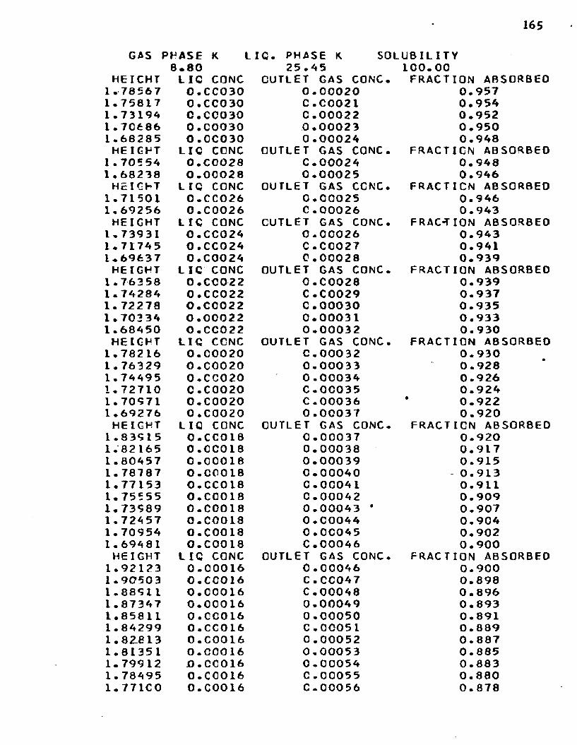
165
GAS PHASE K LIC. PHASE K SOLUBILITY8.80 25.45 100.00
HEICHT LIC CONC OUTLET GAS CONC. FRACTION ABSORBEDI.78567 0.CC030 0.00020 0.9571 * 7 58 L 7 0.C CO 30 C.C0021 0.9541.73194 C .00030 C.00022 0.9521.70686 0 .00030 0.0002 3 0.9501 .68285 0.CC030 0.00024 0.948HEIGHT LIC CONC OUTLET GAS CONC. FRACTION ABSORBED
I.70554 0.C0028 C.00024 0.9481•68238 0 .00028 0.00025 0.946HEIGHT LIC CONC OUTLET GAS CCNC. FRACTION ABSORBED
1.71501 0.CC026 0.00025 0.9461.69256 O.C0026 C .00026 0.943HEIGHT LIC CONC CUTLET GAS CONC. FRACTION ABSORBED
1 .73931 0.CC024 0.00026 0.9431 .71745 0.CC024 C.00027 0.9411.69637 0 • C 0024 0.00028 0.939HEIGHT L IC CONC OUTLET GAS CONC. FRACTION ABSORBED
1.763 58 0. COO22 0.00028 0.9391.74284 0.CC022 C.C0029 0.9371.72278 O.CC022 C.00030 0.9351.70334 0.00022 0.00031 0.9331.68450 0.CC022 0.00032 0.9 30HEIGHT LIC CGNC OUTLET GAS CONC. FRACTION ABSORBED
1.78216 0.00020 C .00032 0.9301.76329 0 .00020 0.00033 0.9281.74495 O.CC020 0.00034 0.9 261.72710 C • C 0020 C.0C035 0.9241.70971 0 .00020 C.00036 0.9221.69276 0 .00020 0.00037 0.920HEIGHT LIQ CONC CUTLET GAS CONC. FRACTION ABSORBED
1.83515 0.CC018 0.00037 0.9201.82 16 5 0 .00018 0.00038 0.9171.80457 0.C0018 0.00039 0.9151.78787 0.00018 C.00040 0.9131.77153 0.CC018 C.00041 0.9111.75555 0.C0018 0.00042 0.9091.73589 0.00018 0.00043 * 0.9071.724 57 0.00018 0.00044 0.9041.70954 O.COO 18 0.00045 0.9021.69481 O.C0018 C .00046 0.900HEIGHT LIQ CONC OUTLET GAS CONC. FRACTION ABSORBED
1.92123 0.00016 0.00046 0-9001.90503 O.CC016 C.CC047 0.8981 .8851 1 0.00016 C.00048 0.8961.87347 0.00016 0.00049 0.8931.85811 0.CC016 0.00050 0.8911.84299 0.CC016 C.00051 0.8891 . 8-2.8 13 0 • COO16 0.00052 0.8871.81351 0.00016 0.00053 0.8851.79912 J0.CC016 0.00054 0.8831.78495 0.CC016 C .00055 0.8801.771C0 0 • COO16 0.00056 0.878

166
1,75726 0.00016 0.00057 0.8761•74372 0.CC016 0.00058 0.8741.73038 0.C0016 0.00059 0.8721.71724 0.00016 0.00060 0.8701.70427 0.C0016 0.00061 0.8671.69148 0.CC016 0.00062 0.865HEIGHT LIC CONC OUTLET GAS CONC. FRACTION ABSORBED
1.75841 0.0C014 0.00083 0.8201.74559 0.00014 0.00084 0.8171.73234 O.CC014 0.00085 0.8151.72121 0.00014 C.00086 0.8131.70521 0.00014 0.00087 0.8111.69653 0.00014 0.00088 0.809HEIGHT LIG CCNC OUTLET GAS CONC. FRACTION ABSORBED
1.76018 0.00012 0.00122 0.7351.74713 0.00012 C.00123 0.7331.73467 0.C0012 0.00124 0.7301.72235 0.00012 C.0C125 0.7281.71016 0.00012 0.00126 0.7261.69719 0.00012 0.00127 0.724HEIGHT LIG CCNC OUTLET GAS CONC. FRACTION ABSORBED
1.75647 O.COOIO 0.00172 0.6261.74275 O.COOIO C.00173 0.6241.72519 0.00010 0.00174 ~~ 0.6221.71578 O.COOIO 0.00175 0.6201.70164 O.COOIO 0.00176 0.6171.68852 O.COOIO 0.00177 0.615HEIGHT LIC CCNC OUTLET GAS CONC. FRACTION ABSORBED
1.78458 O.COOOR 0.00224 0.5131.76658 0.CC008 0.00225 0.5111.74565 0.00008 C. 00226 0.5091.73295 0.C0008 C. 00227 0.5071.71648 0.00008 0.00228 0.5041.69583 0.CC008 C.00229 0.502HEIGHT LIG CONC OUTLET GAS CONC. FRACTION ABSORBED
1.80463 0.00006 0.00277 0.3981 .-78209 0.00006 0.00278 0.3961.75595 0 .00006 0.00279 0.3931.73821 0.00006 C.00280 0.3911.71685 0.C0006 0.00281 0.3891.69515 0.00006 C.00282 0.387HEIGHT LIQ CONC OUTLET GAS CONC. FRACTION ABSORBED
1.84051 0.00004 C. 00330 0.2831.80772 0.00004 0.00331 0.2801.77579 0.00004 0.00332 0.2781.74467 0.CC004 0.00333 0.2761.71431 0.00004 0.00334 0.2741.68468 0.00004 ' 0.00335 0.272

167
G A S 1P H A S E K L IQ. P H A S E K S O L U B I L I T Y8 . 8 0 2 5 . 4 5 6 7 . 0 0
H E I G H T L I C C O N C O U T L E T G A S C O N C . F R A C T I G N A B S O R B E D1 * 7 8 5 0 2 0 . 0 0 0 3 0 C . 0 0 0 2 0 0 . 9 5 71 . 7 5 7 5 3 0 . C C 0 3 0 0 . 0 0 0 2 1 0 . 9 5 41 * 7 3 1 3 0 0 . C C 0 3 0 0 . 0 0 0 2 2 0 . 9 5 21 . 7 0 6 2 3 0 . C C 0 3 0 C . 0 0 0 2 3 0 . 9 5 01 . 6 8 2 2 2 0 . 0 0 0 3 0 C . 0 0 0 2 4 0 . 9 4 8H E I G H T L I Q C O N C O U T L E T G A S C O N C . F R A C T I O N A B S O R B E D
1 • 7 0 4 42 0 . C C 0 2 8 0 . 0 0 0 2 4 0 . 9 4 81 . 6 8 1 2 6 0 . C C 0 2 8 C . C C 0 2 5 0 . 9 4 6H E I G H T L I C C O N C O U T L E T G A S C O N C . F R A C T I O N A B S O R B E D
1 . 7 1 3 1 0 0 . C 0 0 2 6 0 . 0 0 0 2 5 0 . 9 4 61 . 6 9 0 6 7 0 . C C 0 2 6 0 . 0 0 0 2 6 0 . 9 4 3H E I G H T L I C C O N C O U T L E T G A S C O N C . F R A C T I O N A B S O R B E D
1 . 7 * 6 1 0 O . C 0 0 2 4 0 . 0 0 0 2 6 0 . 9 4 31 . 7 1 4 2 7 0 . C C 0 2 4 C . 0 0 0 2 7 0 . 9 4 11 . 6 9 3 21 0 . C C 0 2 4 C . 0 0 0 2 8 0 . 9 3 9H E I G H T L I C C O N C O U T L E T G A S C O N C . F R A C T I O N A B S O R B E D
1 . 7 5 8 2 2 0 . C 0 O 2 2 0 . 0 0 0 2 8 0 . 9 3 91 . 7 3 7 5 3 0 . 0 0 0 2 2 0 . 0 0 0 2 9 0 . 9 3 71 . 7 1 7 5 0 0 . C C 0 2 2 0 . 0 0 0 3 0 0 . 9 3 51 . 6 9 8 1 1 0 . C C 0 2 2 C . C C 0 3 1 0 . 9 3 3H E I G H T L I C C O N C O U T L E T G A S C O N C . F R A C T I O N A B S O R B E D
1 . 7 9 2 5 1 0 . C C 0 2 0 0 . 0 0 0 3 1 0 . 9 3 31 . 7 7 3 1 6 C . C C 0 2 0 C . 0 0 0 3 2 0 . 9 301 . 7 5 4 3 6 0 . C C 0 2 0 C . C C 0 3 3 0 . 9 2 81 . 7 3 6 0 8 0 . 0 0 0 2 0 0 . 0 0 0 3 4 0 . 9 2 61 . 7 1 8 3 1 0 . 0 0 0 2 0 0 . 0 0 0 3 5 0 . 9 2 41 . 7 0 C 9 9 0 . C C 0 2 0 0 . 0 0 0 3 6 0 . 9 2 21 . 6 8 4 1 1 O . C 0 0 2 0 C . C C 0 3 7 0 . 9 2 0H E I G H T L I C C O N C O U T L E T G A S C O N C . F R A C T I O N A B S O R B E D
1 . 8 2 3 4 4 0 . C 0 0 1 8 0 . 0 0 0 3 7 0 . 9 2 01 . 8 0 6 0 9 0 . C C 0 1 8 C . 0 0 0 3 8 0 . 9 1 71 . 7 8 9 1 5 0 . C C 0 1 8 C . 0 0 0 3 9 0 . 9 1 51 . 7 7 2 5 8 0 . C O O 18 0 . 0 0 0 4 0 0 . 9 1 31 . 7 5 6 3 8 0 . 0 0 0 1 8 0 . 0 0 0 4 1 0 . 9 1 11 . 7 4 0 5 3 0 • C O O 18 0 . 0 0 0 4 2 0 . 9 0 91 . 7 2 5 0 2 0 . C C 0 1 8 C . 0 0 0 4 3 0 . 9 0 71 . 7 0 5 8 2 0 . C O O 18 0 . 0 0 0 4 4 0 . 9 0 41 . 6 9 4 9 2 0 . C 0 0 1 8 0 . 0 0 0 4 5 0 . 9 0 2H E I G H T L I C C O N C O U T L E T G A S C O N C . F R A C T I O N A B S O R B E D
1 . 9 0 8 9 2 0 . C C 0 1 6 C . O C 0 4 5 0 . 9 0 21 . 8 9 2 7 3 0 . 0 0 0 1 6 0 . 0 0 0 4 6 0 . 9 0 01 . 8 7 6 8 2 0 . 0 0 0 1 6 0 . 0 0 0 4 7 0 . 8 9 81 . 8 6 1 2 0 0 . C C 0 1 6 0 . 0 0 0 4 8 0 . 8 9 61 . 8 4 5 8 6 O . C C 0 1 6 C . C 0 0 4 9 0 . 8 9 31 . 8 3 0 7 8 0 . C O O 16 C . 0 0 0 5 0 0 . 8 9 11 . 8 1 5 9 6 0 . 0 0 0 1 6 0 . 0 0 0 5 1 0 . 8 8 91 . 8 0 1 3 7 O . C C 0 1 6 C . 0 0 0 5 2 0 . 8 8 71 . 7 8 7 0 3 0 . C C 0 1 6 C . C C 0 5 3 0 . 8 8 51 . 7 7 2 9 1 0 . 0 0 0 1 6 0 . 0 0 0 5 4 0 . 8 8 31 . 7 5 9 0 1 0 . 0 0 0 1 6 0 . 0 0 0 5 5 0 . 8 8 01 . 7 4 5 3 2 0 . C C 0 1 6 0 . 0 0 0 5 6 0 . 8 7 8

168
1 . 7 3 1 8 5 C . C 0 0 1 6 C . 0 0 0 5 7 0 . 8 7 61 . 7 1 8 5 7 0 . C 0 0 1 6 0 . 0 0 0 5 8 0 . 8 7 41 . 7 0 5 4 9 0 . 0 0 0 1 6 C . 0 0 0 5 9 0 . 8 7 21 . 6 9 2 6 0 0 . C C 0 1 6 C . 0 0 0 6 0 0 . 8 7 0H E I G H T L I C C C N C O U T L E T GAS C O N C . F R A C T I O N A B S O R B E D
1 . 7 5 1 2 8 0 . 0 0 0 1 4 C . 0 0 0 8 0 0 . 8 2 61 . 7 3 8 9 8 0 .00014 0 . 0 0 0 8 1 0 . 8 2 41 . 7 2 6 8 2 0 . C C 0 1 4 C .00082 0 . 8 2 21 . 7 1 4 7 8 0 . C 0 0 1 4 C . 0 0 0 8 3 0 . 8 2 01 . 7 0 2 7 2 0 • C O O 14 0 . 0 0 0 8 4 0 . 8 1 71 . 6 9 C 9 4 0 . 0 0 0 1 4 C . 0 C 0 8 5 0 . 8 1 5H E I G H T L IC C O N C O U T L E T G AS CONC. F R A C T I O N A B S O R B E D
1 . 7 5 3 4 8 0 . 0 0 0 1 2 C . 0 0 1 1 7 0. 7461 . 7 4 1 1 5 0 • COO 12 0 . 0 0 1 1 8 0 . 7 4 31 . 7 2 8 5 6 0 . 0 0 0 1 2 0.001 19 0.7411 . 7 1 6 5 0 0 . C C 0 1 2 C . 0 0 1 2 0 0 . 7 3 91.704 5 5 0 . C C 0 1 2 C . 0 0 1 2 1 0 . 7 3 71 . 6 9 2 7 2 0 . 0 0 0 1 2 0 . 0 0 1 2 2 0 . 7 3 5H E I G H T LIQ C C N C O U T L E T GAS CONC. F R A C T I O N A B S O R B E D
1 . 7 5 5 7 4 O . C O O I O C . 0 0 1 6 5 0 .6 4 11 . 7 4 2 4 0 O . C O O I O C . 0 0 1 6 6 0 . 6 3 91 . 7 2 5 2 3 O . C O O I O 0 . 0 0 1 6 7 0 . 6 3 71 . 7 1 5 8 2 0 . 0 0 0 1 0 0 .00168 0 . 6 3 51 . 7 0 2 9 4 O . C O O I O C . 0 0 1 6 9 0 . 6 3 31 . 6 9 C 2 0 O . C O O I O C. 0 0 1 7 0 0 . 6 3 0H E I G H T L I Q C O N C O U T L E T GAS CONC. F R A C T I O N A B S O R B E D
1 . 7 9 3 9 4 0 . 0 0 0 0 6 0 . 0 0 2 6 9 0 . 4 1 51 . 7 7 2 7 1 0 . C C 0 0 6 C . 0 0 2 7 0 0 . 4 1 31 . 7 5 1 8 3 0 . C 0 0 0 6 0 . 0 0 2 7 1 0 . 4 1 11 . 7 3 0 9 7 0 . 0 0 0 0 6 C . 0 0 2 7 2 0 . 4 0 91 . 7 1 C 7 7 0 . 0 0 0 0 6 C. 0 0 2 7 3 0 . 4 0 71 . 6 9 C 8 9 0 . C C 0 0 6 C .00274 0 . 4 0 4H E I G H T LI C C O N C O U T L E T GAS C O N C . F R A C T I O N A B S O R B E D
1 . 8 3 5 6 0 0 . 0 0 0 0 4 0 . 0 0 3 2 1 0 . 3 0 21 . 8 0 5 2 3 0 .0 0 0 0 4 0 . 0 0 3 2 2 0. 3001 . 7 7 5 5 7 0 . 0 0 0 0 4 C . C 0 3 2 3 0. 2981 . 7 4 6 6 2 0 . 0 0 0 0 4 C .00324 0 . 2 9 61 . 7 1 8 3 1 0 . 0 0 0 0 4 C . 0 0 3 2 5 0 . 2 9 31 . 6 9 0 6 1 0 . 0 0 0 0 4 0 . 0 0 3 2 6 0 . 2 9 1

APPENDIX I
SAMPLE CALCULATIONS
A. Contact Time
System: C02 “ H^O
Run I
Jet Length 3. Mtl cm.
Liquid Flow Rate 2. 55 cc./sec.
Mean Diameter 1. l*t mm. from Figure 10.
, _ Volume of Jet Element Flow Rate
, = (3. 1*0 (. llfr cm.) (3.Mtl cm.) = 0 U 81 (It) (2. 55 cc. /sec. ) -0138
l//t' = 8 . 5 sec. “ 1/2
B. Mass Transfer Flux
System: C02 - H^O
Run 1
Average Absorption Rate . 0490 cc./sec.
Mean Diameter 1. Ik mm. (see A above)
Jet Length 3.kkl cm.
sec.
169
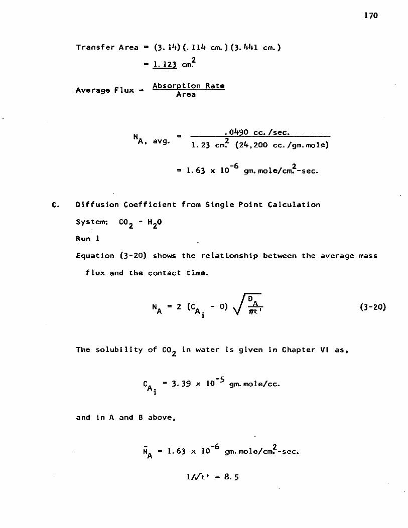
Transfer Area “ (3* 14) (. 1 14 cm. ) (3. 441 cm.)
- 1. 123 cm?
Average Flux = Absorption Rate Area
N . 0490 cc. /sec.A, avg. 21.23 cm. (24,200 cc. /gm. mole)
-6 2 ■ 1.63 x 10 gm. mole/cm.-sec.
Diffusion Coefficient from Single Point Calculation
System: C02 - H20
Run 1
Equation (3~20) shows the relationship between the average mass
flux and the contact time.
The solubility of C02 in water is given in Chapter VI as,
(3-20)
C. = 3. 39 x 10 ^ gm. mole/cc. i
and in A and B above,
“ "6 2 N. = 1.63 x 10 gm. mole/cm.-sec.

171
Rearranging Equation (3-20) to solve for D.;
_ 20 - V . ” _ ( 1 .63 x 1 0 ~ V ( 3 . 14) ( .0 1 3 8 )A 4 (CA )2 (*0 (3.39 x 10"5)2
A i
-5 23 2. 5 x 10 cm. /sec.
D. Contact Time
System: Sodium Hydroxide - Methyl Mercaptan
Run 102
Liquid Flow Rate 2. 55 cc./sec.
Jet Length 3.6^*6 cm.
Mean Diameter 1. 16 mm. from Figure _10
, = Volume of Jet Element Flow Rate
i i ■ 386 cm. ait 1 = -----*— r------ = .0151 sec.2. 55 cm* / s e c .
C. Mass Transfer Flux
System; Sodium Hydroxide - Methyl Mercaptan
Run 102
Average Absorption Rate . 255 cc./sec.
Mean Diameter 1. 16 mm.
(at liquid flow rate and jet length)
Jet Length 3.6*i6 cm.
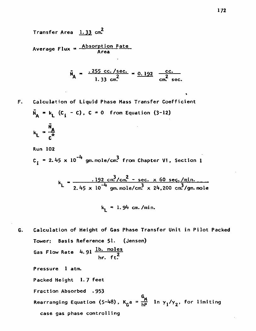
172
2Transfer Area 1. 33 cm.
Absorption Rate Average F l u x --------- jfjjj--------
M. - - 2S? cc./sec.. _ o 19Z — ££:--1. 33 cm. cm. sec.
F. Calculation of Liquid Phase Mass Transfer Coefficient
(Cj - C ) , C “ 0 from Equation (3“ 12)
SA
Run 102“If 3C. = 2.^5 x 10 gm.mole/cm. from Chapter VI, Section 1
3 2. = .192 cmr/cm. - sec, x 60 sec./min._____L = -1+ 3 32.1+5 x 10 gm.mole/cm. x 2l+,200 cmr/gm. mole
k^ =* 1. 94 cm./min.
G. Calculation of Height of Gas Phase Transfer Unit in Pilot Packed
Tower: Basis Reference 51. (Jensen). 1 . , 1. a 1 lb. molesGas Flow Rate 4. 91 -------- 5“
hr. ft.
Pressure 1 atm.
Packed Height 1. 7 feet
Fraction Absorbed .953GMRearranging Equation (5-i+8) , K^a = '̂ p In for limiting
case gas phase controlling

173
y l ' y2 — = 1 - y2/Vl = -953
Vl/y2 = 21. 1
k a =. (fr- lp [21 n . (4. 9.1).(L^L7).V (1.7) (1) 1 7
K a - 8,1 lb~ ™ les--- ( 4 )hr. ft. (atm.) ft.
6m[Height of Transfer Unit]_ = H„ ■ ----Gas G KpSp
For gas phase controlling
1 ~ 1KGa kGa
HG “ irfp = (8^8) (1) = ‘ 56 ft'
H. Calculation of Height of Liquid Phase Transfer Unit in
Pilot Packed Absorber2Gas Flow Rate 4.91 lb. moles/hr. - ft.
Liquid Flow Rate 3100 lb. /hr. - ft? _
Pressure 1 atm.
Packed Height 1. 7 feet
Fraction Absorbed with Water . 159
V ■ hP ln y l/y2 " • 501
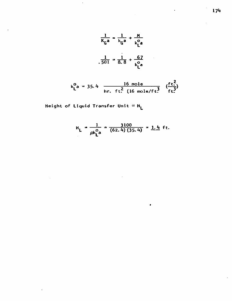
.o 16 molek. a - 35- h ------- 5---------------7hr. ft. (16 mole/ft.
Height of Liquid Transfer Unit =
H L_ = mo ! 4L pk£a (62. (35- —
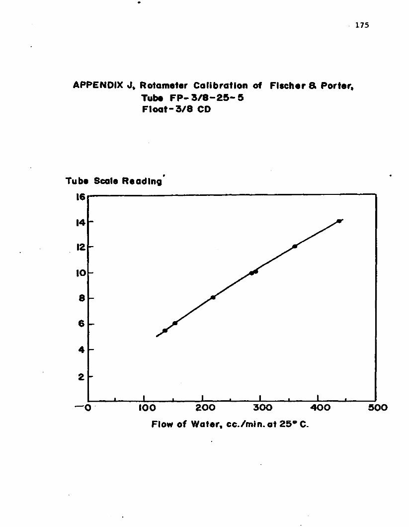
175
APPENDIX J , R o tam eter C a lib ra tio n of F isc h e r & P o rte r , Tube F P - 3 / 8 - 2 5 - 5 F l o a t - 3 /8 CD
T ube Scale R e a d in g '
16
14
12
10
86
4
2
3 0 0 4 0 0 5 0 0— O 200I O O
Flow o f W ate r, c c . /m in .a t 2 5 ° C.

AUTOBIOGRAPHY
Josephy Earl Landry was born January 6, 1936 in St. Martinville,
Louisiana. He attended St. Martin Parish schools and graduated from
Breaux Bridge High School in 195**. He entered the University of
Southwestern Louisiana in 195^ and graduated with a Bachelor of
Science degree in Chemical Engineering.
After graduation he accepted a position as Research Chemical
Engineer in Allied Chemical's Baton Rouge Development Laboratory
and in January 1959 he began attending night graduate courses at
Louisiana State University.
In June 1962, he accepted a position on the staff of the
Louisiana State University Division of Engineering Research as a
Research Associate in a project sponsored by the National Council for
Stream Improvement (of the Pulp, Paper, and Paperboard Industries).
In August of 1963 he received the Master of Science degree in
Chemical Engineering and is presently a candidate for the degree
of Doctor of Philosophy in the Department of Chemical Engineering.
176

EXAMINATION AND THESIS REPORT
Candidate: Joseph Earl Landry
Major Field: Chemical Engineering
Title of Thesis. £ffect Qf ^ Second Order Chemical Reactionon the Absorption of Methyl Mercaptan In a Laminar Liquid Jet Approved:
Major Professor and Chairman
Dean of the Graduate School
EXAMINING COMMITTEE:
KJUiS
Date of Examination:
July 15, 1966