the diffraction of a plane wave through a grating* john … · the diffraction of a plane wave...
TRANSCRIPT

45
THE DIFFRACTION OF A PLANE WAVE THROUGH A GRATING*BY
JOHN W. MILESUniversity of California at Los Angeles
Summary. The problem of diffraction and scattering of a normally incident planewave of sound by an infinite plane grating consisting of infinitely thin, coplanar, equallyspaced (b apart) strips with parallel edges is solved. The potentials on the two sides ofthe screen are written as Fourier expansions in terms of the velocity in the aperture, andan integral equation for this velocity is determined. An impedance parameter Z whosereal part is the transmission coefficient, is defined, and it is shown that the real and imagi-nary parts of the reciprocal of this parameter may both be specified by variational ex-pressions, which are absolute minima for the solution to the aforementioned integralequation. An alternative formulation, in terms of the pressure discontinuity across thescreen, is given, leading to an integral equation and to variational expressions for the realand imaginary parts of (1 — Z)'1. A solution to the integral equation is given whichreduces the problem to the solution of an infinite number of simultaneous equations. Itis shown that solving only one of these equations gives a solution which is essentially asolution to Laplace's equation, while if N equations are solved the terms neglected areof the order iV—x[(l — 4b2/N2\2)~1/2 — 1] or less, where X is the wave length. The solutionis extended to the case of a vertically polarized electromagnetic incident wave by directanalogy and to the case of a horizontally polarized electromagnetic wave by a transforma-tion which is a special case of Babinet's principle. The integral equations for an apertureof finite thickness are set up, and an approximate solution including only first order termsin thickness/wavelength is given. Results are given in the form of curves for the trans-mission coefficient vs. aperture opening for several ratios of grating spacing to wavelength less than unity. For the special case of a half open grating the transmission coeffi-cient is plotted out to that value of spacing/wavelength at which the results agree withKirchhoff's theory.
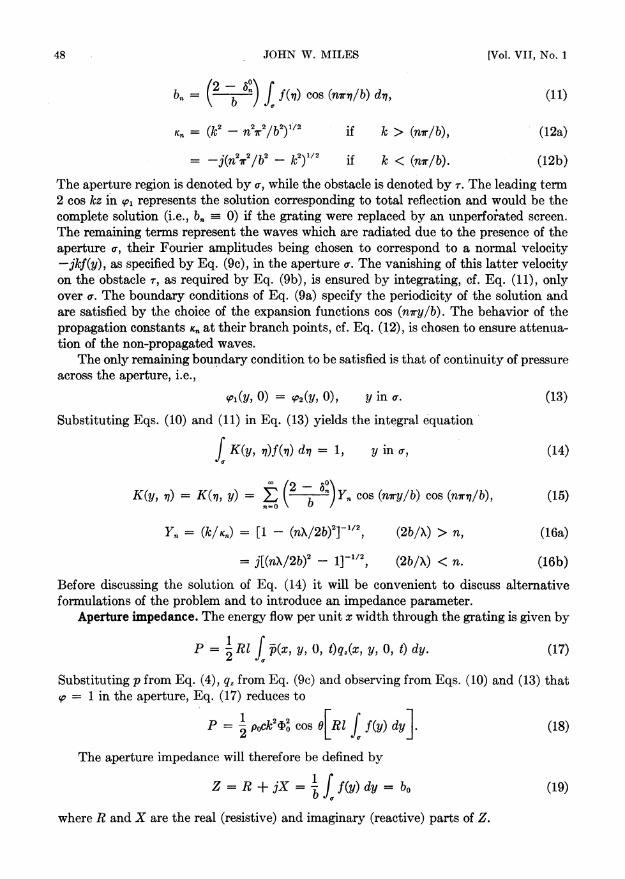
Introduction. The problem to be solved is the scattering and diffraction of a planewave of sound which is (essentially) normally incident upon a plane grating consisting ofan infinite number of infinitely thin parallel ribbons of width b — d whose centers arespaced a distance b apart, as shown in Fig. 1. Since, by symmetry, the normal velocitymust vanish at the planes which form the perpendicular bisectors of the ribbons, shownby dashed lines in Fig. 1, the problem is the same as the calculation of the transmissionof sound through a symmetrical window of opening b — d placed perpendicular to two,infinite, parallel plates, a distance b apart. This problem, subject to certain restrictionson the frequency, has been treated by the present author.1 For the sake of completenessand in order to investigate further the limitations on the frequency, the analysis will becarried out independently of earlier papers.
The solution will be formulated in terms of the normal velocity in the plane of thegrating, which, by virtue of Huygen's principle, may be regarded as a source distribution.
*Received March 18, 1948.'John W. Miles, The analysis of plane discontinuities in cylindrical tubes, J. Acoust. Soc. Am. 17,
Part I: 259-272, Part II: 272-285 (1946). The variational methods used therein were due toJ. S. Schwinger.

46 JOHN W. MILES [Vol. VII, No. 1
The potentials on the two sides of the screen may then be regarded as composed of thesolution corresponding to no aperture in the screen (i.e., complete reflection) plus radia-tion from the unknown source distribution over the aperture. The normal derivatives ofthe potentials on the two sides of the screen will then automatically satisfy appropriateboundary conditions, while the requirement that the potentials themselves be continuous
X OOt
IOO
0.—- yT -Lb d
I T
IOO
Fig. 1. Three views of infinite grating.
across the aperture yields an integral equation for the determination of the source dis-tribution (or aperture velocity). An alternative formulation in terms of the pressurediscontinuity across the screen will also be given.
In many cases, it is sufficient to know the transmission coefficient for the grating, i.e.,the ratio of the energy density transmitted through the grating to that in the incidentwave. It is convenient to introduce a complex impedance parameter, whose real part isthe transmission coefficient, and this leads to a variational formulation of the problem.

1949] DIFFRACTION OF A PLANE WAVE THROUGH A GRATING 47
Velocity potentials. Is is known2 that if the velocity vector q is specified as thegradient of a potential 4> and a harmonic time variation exp (jut) is assumed, the potentialsatisfies the scalar Helmholtz equation
V2<l>(x, y, z) + k2<t>{x, y, z) = 0, (1) k = u/c, (2)
q(z, y, z, t) = exp (jut)V<t>(x, y, z), (3)
while the pressure is given by
p(x, y, z, t) = -jcopo exp (jo)t)<j>(x, y, z). (4)
If the incident wave from z — — °° has its wave normal in the xz plane, it may bedesignated by
<t>indx, y, z) = $0 exp [~jk(x sin 9 + z cos 0)], (5)
where the axes are as shown in Fig. 1. It is evident (since there is no discontinuity in thex direction) that the dependence on the x coordinate, together with the amplitude <3?0 ,may be removed by writing
4>{x, y, z) = 4>o exp (—jkx sin 8)<p(y, z), (6)
VV(2/, z) + «VG/, 2) = 0, (7)where
k = k cos 6. (8)
It follows that the solution for 6^0 may be obtained from the solution for 6=0 simplyby replacing k in the latter by k cos 6 and multiplying the result by exp (—jkx sin 6).Accordingly, only the case 0 = 0 will be discussed in the following sections.
A solution to the foregoing equations which is periodic in y, corresponding to thepeiiodicity of the grating, which corresponds to the incident wave (5), and which satisfiesthe boundary conditions
g(0 ,z) =ff(M) = 0, (9a)
(y, 0) = 0 , y in r, (9b)
= ~jkf(.y), V in <r, (9c)
is given bya>
z < 0 : <pi(y, z) = 2 cos kz — k X) exp (jnnz) cos (rnry/b), (10a)71 = 0
CO
z > 0 : <p2(y, z) = fc bnn~l exp (—jnnz) cos (rnry/b), (10b)
2P. M. Morse, Vibration and sound, McGraw-Hill, New York, 1936.
48 JOHN W. MILES [Vol. VII, No. 1
k" = (2 b 5") / /W cos (nW&) dt], (11)
Kn = (k2 - nV/b2)i/2 if k > (nir/b), (12a)
= -j(nV/b2 - fc2)1/2 if k < (7171-/6). (12b)
The aperture region is denoted by a, while the obstacle is denoted by r. The leading term2 cos kz in <pt represents the solution corresponding to total reflection and would be thecomplete solution (i.e., bn = 0) if the grating were replaced by an unperforated screen.The remaining terms represent the waves which are radiated due to the presence of theaperture <r, their Fourier amplitudes being chosen to correspond to a normal velocity—jkf(y), as specified by Eq. (9c), in the aperture a. The vanishing of this latter velocityon the obstacle r, as required by Eq. (9b), is ensured by integrating, cf. Eq. (11), onlyover a. The boundary conditions of Eq. (9a) specify the periodicity of the solution andare satisfied by the choice of the expansion functions cos (niry/b). The behavior of thepropagation constants nn at their branch points, cf. Eq. (12), is chosen to ensure attenua-tion of the non-propagated waves.
The only remaining boundary condition to be satisfied is that of continuity of pressureacross the aperture, i.e.,
0) = <p2(y, 0), y in <r. (13)
Substituting Eqs. (10) and (11) in Eq. (13) yields the integral equation
[ K{y, rf)f (17) dri = 1, y in a, (14)J a
K(y, ri) = K{t], y) = ^ i~b~^)Yn cos (nir2//b) cos (15)
F„ = (k/Kn) = [1 - (nX/2&)T1/2, (2b/\) > n, (16a)
= j[(rik/2b)2 - 1]'1/2, (26A) < n. (16b)
Before discussing the solution of Eq. (14) it will be convenient to discuss alternativeformulations of the problem and to introduce an impedance parameter.
Aperture impedance. The energy flow per unit x width through the grating is given by
P = IRl I ^X' V' °' ^q^X' V' °' ^ dy" ^
Substituting p from Eq. (4), qz from Eq. (9c) and observing from Eqs. (10) and (13) thattp = 1 in the aperture, Eq. (17) reduces to
P = | pack2<Pl cos d^Rl f(y) dy (18)
The aperture impedance will therefore be defined by
Z = R + jX = | ^ Ky) dy = b0 (19)
where R and X are the real (resistive) and imaginary (reactive) parts of Z.
1949] DIFFRACTION OF A PLANE WAVE THROUGH A GRATING 49
Now in Kirchhoff's theory3 of diffraction it is assumed that the fields in the apertureare the same as they would be in the absence of r, i.e., 4>i(x, y, 0) = <f>2(x, y, 0) =<t>inc{x, y, 0), in which casef(y) = 1. The ratio of actual tramsmitted energy to that pre-dicted by Kirchhoff's theory is therefore given by
p/p*-©If I™ "*]-(!)*• (2o)The reactance term X is a measure of the non-propagated energy stored in the vicinity
of the aperture, i.e. of the standing waves.It may be remarked that the impedance defined by Eq. (19) is closely analogous in
the quantity utilized by Rayleigh in his studies of apertures in cavities.4 On the otherhand, the impedance differs from that defined in the paper quoted in Footnote 1 inincluding the "radiation resistance" R, and, as will be shown subsequently, also in thedefinition of the imaginary component.
Variational formulation. Multiplying both sides of Eq. (14) by / (y) dy, integratingover the aperture, and dividing through by Eq. (19) yields
Z'1 = y = G + jB = b £ f(y) dy ̂ f(ri) djj] ^ f(y) dy jf f(v)K(y, „) dr,. (21)
Equation (21) is a variational equation of a type first studied by Schwinger5, althoughin the present case both the kernel K and the unknown function / are complex. In orderto further study the properties of Eq. (21), it is expedient to reduce it to two real expres-sions. Thus, write
f(y) = fi(y) + jfiiy), (22)
K(y, v) = KXy, v) + jK2(y, v) (23)where/i and/2 are both real functions, and /v, and K2 are the real and imaginary partsof the kernel, corresponding to the Yn of Eqs. (16a,b).
Substituting Eqs. (22) and (23) in Eq. (21), remembering the symmetry of the kernelin (y, v), yields
G =&[(//. d») +([f d»)]
• \_l fx dy J fiKi dv + JJ2dy J f2Kx d„],
+ (I UdyfY■ \_l /. dy J fiK2 dv + J f2dy J f2K2 d,].
(24a)
(24b)
3J. A. Stratton, Electromagnetic theory, McGraw-Hill, New York, 1941. Since the Kirchhoff calcula-tion is generally carried out by integrating the flux through a hemisphere, the results designated asKirchhoff herein might more precisely be labelled geometric.
4Lord Rayleigh, Theory of sound, Dover Press, New York, 1946.6At the M. I. T. Radiation Laboratory (1941-1945); see also the paper quoted in Footnote 1.

50 JOHN W. MILES [Vol. VII, No. 1
Similarly the integral equation (14) may be rewritten:
[ [Ki(y, „)/,(„) - K2(y, v)f2(„)] dv = 1, (25a)J a
f [K,(y, „)/,(„) + K2(y, v)Mv)] dr, = 0. (25b)
Now by varying G and B as given by Eqs. (24), with respect to both /, and f2, it is foundthat the functions /i and f2 which satisfy Eqs. (25) make both G and B stationary.Moreover, from the symmetry of K, and K2 , both G and B are positive definite forms(since they will be sums of squares), and it follows that they are absolute minima withrespect to variations about the true functions fi and f2. The formal proof is analogous tothat given in Appendix C of the paper quoted in Footnote 1 for the variational expressionobtained by assuming that /x and f2 differ only by a constant in Eq. (24b).
A closer analogy to the cases treated in the author's earlier paper1 is obtained byassuming X > b, as assumed therein, in which case it follows from Eq. (15) that Kx = 1,and Eq. (24a) reduces to
G = 1 if X > b cos d (26)
In this case, it may be assumed that f2 = 0, and it is found that the susceptance B ishalf that for the symmetrical window mentioned in the Introduction to the present paper.
Alternative formulation. The problem can also be formulated in terms of the pressurediscontinuity across the screen, defined by
7(y) - | My, 0-) - <p2(y, 0+)]. (27)
In terms of y(y), the potentials may be written
<pl(y, z) = exp (-jkz) ± dn exp (±jicAz) cos (rnry/b), (28)n=0
dn = ^ S""j f y(y) cos (mry/b) d-q. (29)
The potentials given by Eq. (28) evidently satisfy Eq. (13) implicitly, since theFourier coefficients are so defined. Moreover, differentiation shows that the normalvelocity is continuous at z = 0, so that Eq. (9c) is satisfied. It remains to satisfy Eq. (9b)by demanding the integral equation.
^ H{y, rj)y(v) di) — 1, y in r, (30)
H{y, v) = (2 b S"^Zn cos (rnry/b) cos (mrri/b), (31)
Zn = Y;1 = k~\k2 - (tmt/?>)2]1/2. (32)

1949] DIFFRACTION OF A PLANE WAVE THROUGH A GRATING 51
From Eqs. (9b) and (27) it is evident that y{y) and f(y) are related by.
f(y) = 1 _ { H(y, vh(v) dv, (33a)
7(y) = 1 - f K(y, rf)f(rj) dr), (33b)o
so that the Fourier coefficients of / and 7 are related by
b„ + dn = d°n . (34)
For n = 0, Eqs. (34) and (19) yield
Z = 1 — | J 7(17) dr1. (35)
Multiplying both sides of Eq. (30) by 7 (y) dy, integrating over the obstacle, and divid-ing through by 1 — Z from Eq. (35) yields the variational expression
(i - zy1 = b J' 7(y) dy ^ 7(77) dr] ^ 7(y) dy J 7(77)H(y, 77) (Z77J. (36)
Now Eq. (36) is exactly analogous to Eq. (21), and it may be shown that its real andimaginary parts are absolute minima with respect to variations of 7 (y) about the truevalue of 7(y) satisfying the integral equation (30). In order to compare the results soobtained, it may be observed that
(1 - Z)"1 ='t(l - Gf + B2]_1[(l - G) + jB}. (37)
For the special case where Eq. (26) holds, it is seen that Eq. (36) makes l/B a minimum,and the results of Eqs. (24b) and (36) therefore bound B from above and below. This casewas treated before.1 For the case where the wavelength is less than b Eq. (24) boundsG and B from above, while Eq. (36) bounds [(1 — G) + (1 — (?) 'B2} and [B + B~l{ 1 —G)2] from below.
Solution to the integral equation. In the problem at hand, the most appropriateattack appears to be an approximate solution to the integral equation (14). The accuracyof the solution can then be checked by substituting the solution so obtained in the varia-tional expression (21) and by calculating 7 from Eqs. (33) and (34) and substituting inEq. (36).
In order to solve Eq. (14), the first step is to rewrite the kernel K(y, ri) as
K(y, 77) = b 1 + j(2k/ir) ^2 n 1 cos (nvy/b) cos {mrq/b)n= 1
+ (2k/ir) ^2 A„ cos (niry/b) cos (mri)/b),
(38)
An = w-1{[(2b/nX)2 - 1]-1/2 - j), (2&A) > n, (39a)
= jn_1{[ 1 - (2b/nX)2]-U2 - 1}, (2bA) < n. (39b)

52 JOHN W. MILES [Vol. VII, No. 1
The second term in Eq. (32) may be written in closed form, sinceCO
2 23 n'1 cos (nz) cos (nt) — — ln[2 | cos z — cos f |], (40)n= 1
whence
K(y, v) = b'1 - j(Jc/ir) In [2 | cos (try/b) - cos (jy/b) |]
(41)+ (2fc/x) 23 cos (niry/b) cos (tiTri/b).
n = 1
Before substituting Eq. (41) in Eq. (14), it is expedient to introduce the change ofvariable
cos (iry/b) = a cos 0, (42a) a = sin (ird/2b), (42b)
u(d) — a(l — a cos2 B)~1/2f[(b/ir) cos"1 (a cos 0)] sin 0. (43)
Substituting Eqs. (42) and (43) in Eq. (14) yields
— [ bK(6, dip =1, 0 < 0 < t, (44)IT J o
bK{6, ip) = 1 — j (kb/ir) In [2a | cos 0 — cos ^ |]
+ (2kb/ir) 23 cos (n-rry/b) cos (mrri/b)n= 1
(45)= [1 — j (kb/ir) In a] + j(2kb/ir) 23 n 1 cos nO cos mp
n= 1
+ (2kb/ir) 23 An cos (rnry/b) cos {nirr\/b),71= 1
where y, r\ and 0, \p in the last term are understood to be related by Eq. (42). Now expandu{6) in the Fourier series
oo
u(6) = cos (n0). (46)n = 0
Substituting Eq. (46) in Eq. (44) yields
[1 — j(kb/ir) In a]a0 + j(kb/tr) 23 cos (nd)n= 1
(47)00 CO
+ (kb/ir) 23 COS (ricy/b) 23 aJr, = 1,r = 1 « =0
2 rrIr, = - / cos [r cos 1 (a cos ^)] cos (si^) d\j/. (48)
7T Jq
1949] DIFFRACTION OF A PLANE WAVE THROUGH A GRATING 53
Moreover, since lmn are the Fourier expansion coefficients of cos (nry/b), Eq. (47) maybe rewritten
GO
[1 — j(kb/ir) In a] <z0 + j(kb/v) Z °^n~1 cos (n#)n— 1
(49)
+ (kb/ir) X) Ar (1 + COS (jld) ^ CLsIr, = 1.r = 1 n=0 8 = 0
Now, since Eq. (49) must be valid for all 0 between 0 and w, it follows that
5o[l - j(kb/ir]) In a]a0 + (kb/w){j( 1 - 5°)w_1a„
(50)+ Z (1+ O"1 ArZrn £ Zr,as} = 5° , n = 0, 1, 2, • • •
r=l 8=0
which is an infinite set of simultaneous equations for the determination of the dn.While it would have been simpler to solve the integral equation (12) by a direct Fourier
expansion in cos (niry/b), leading to a set of simultaneous equations for the Fourier coeffi-cients, the transformation to the 0 coordinate allows the separation of the In a term, whichis essentially the susceptance in the limit of zero frequency.
The Irs integrals may be easily evaluated by an identity due to Jacobi6
[ 0(cos 0) cos (w0) d6 = [1-3- • • • (2n — 1)] 1 /* ^ *^cos ^ (sin 0)2n d6. (51)Jo o d( cos 0)"
Nowr
cos (rinri/b) = X <y/(cos 0)", (52a)p—0
c'v = coeff. of (cos x)" in expansion of cos (nx), (52b)
whence.it follows that
d IT = X p(p - 1) • • • (p - s + l)cpV(cos ey~n, s <rd\cos 6) p=3 (53)
= 0 , r < sUsing the result
fa (cos 0)m(sin 0)" dd = !~:) (54)
where B is the Beta function, it follows that
ir, = - [i-3 ■■■ (2s- D]-1 i:""" P = 8
/ ^ i \ r vJv - S + 1 2s + 1^ ^ (55)■p(p - 1) • • • (p - s + l)cva By- , —-—J, r > s,
= 0, r < s.6H. Batcman, Partial differential equations, Dover Press, New York, 1944, p. 463. (Note that the
first integral given by Bateman on the top of p. 464 is incorrect and is not used here.)

54 JOHN W. MILES [Vol. VII, No. 1
In the present case, due to symmetry, only even values of r and s need be considered,so that p — s and 2s will be even, in which case
gg(P -* + \ *±1) = _ s)!(2s)! (56)
In an approximate solution, only a finite number, say N, of Eqs. (50) will be solved.The error in solving N equations will evidently be of order AN at worst. While the A„(cf. Eq. 39) generally decrease with increasing n, each possesses a singularity at b/\ = n/2,so that it will generally be necessary to satisfy the inequality
N > (26/X). (57)It should also be remembered that, due to symmetry, the odd An vanish identically,
and the number of equations to be solved for a given N is actually only (N + l)/2.Electromagnetic problem. The case of a plane electromagnetic wave normally in-
cident on a grating (assumed perfectly conducting at radio frequencies or perfectlyreflecting at optical frequencies) is analogous to the above acoustical problem since, dueto the normal incidence, it is possible to derive all six components of the electromagneticfield from a single component of the incident field, provided that the cases of vertical(electric field) and horizontal polarization of the incident wave are treated separately.
Vertically polarized wave. Consider first the vertically polarized incident waveconsisting of the fields
H0 = iH°x exp (—jkz), (58a)
E0 = —jH°x exp (~jkz), (58b)
which satisfy Maxwell's equations (MKS units)
V X E = -jkH, (59a)
V X H = jkE, (59b)
V-E =0, (60a)
V H = 0. (60b)The boundary conditions to be satisfied in the screen are
Ex = Ey = Hz <= 0, (61)
only two of which are independent, according to Eqs. (59). Finally, each of the fieldcomponents satisfies the scalar Helmholtz equation (1), which follows directly fromMaxwell's equations (59) and (60).
Now in the case of the incident wave (58), it is evident that the entire problem may beformulated in terms of field components Hx ,EV, and E,. Moreover, from Eqs. (59), it isseen that
jkEy(y, z) = (y, z), (62a)
n TT
jkE Ay, z) = - (y, z), (62b)
1949] DIFFRACTION OF A PLANE WAVE THROUGH A GRATING 55
which satisfy Eqs. (59) and (60). Therefore, it is evident from comparing Eqs. (5) and(58a), (9b) and (61b), and (9c) and (61b) that
Hi o, (63a)
Hx(y, z) ~ $0<p(y, z), (63b)
Ev(y, 0) ~ $0f(y). (63 c)
It follows that the foregoing acoustical problem yields a direct solution to the electro-magnetic problem when the incident wave is plane and vertically polarized. (It may alsobe shown that the pressure discontinuity y is analogous to the current induced in thescreen by the magnetic field.)
Horizontally polarized wave. A horizontally polarized incident field consists of thecomponents
E0 = iE"x exp (—jkz), (64a)
H„ = jE°x exp (—jkz). (64b)
Consider now the solution
2^0: El'(y, z) — Eas exp (—jkz) — k ^ bnKexp (± j°nnz) cos (niry/b)\, (65a)I n = 0 J
z § 0 : Hl'(y, z) = #°{exp (—jkz) ± ^ bn exp (±jicnz) cos (niry/b)\. (65b)k n = 0 )
It is evident, that Eq. (65) corresponds to Eq. (64) and satisfies Eqs. (59) and (60).Moreover, if f(y) is a solution to Eq. (14) in the plane 2 = 0, the following conditions aresatisfied:
El(y, 0) = El(y, 0) , * 0 < y < b, (66a)
El(y, 0) = El(y, 0) = 0 , y in «r, (66b)
H\(y, 0) = Hl(y, 0) = El , y in r, (66c)
Hl(y, 0") - Hl(y, 0+) = 2E°J(y) , y in «r. (66d)Hence, it follows that Eq. (65) represents a solution to Maxwell's equations which
satisfies boundary conditions appropriate to the complementary grating, i.e., that gratingobtained by interchanging aperture a and obstacle r of the original grating. This resultis a special case of Babinet's principle, which, in its rigorous form, has been discussed byCopson7, following Booker, by Watson8, and by Schwinger9.
From Eq. (66d) it is evident that/(?y) in the present case represents the current flowingin the screen, whereas in the case of the vertically polarized incident wave /(?/) representedthe tangential electric field in the aperture. Conversely, it may be observed that an alter-native solution for the present case is given by
7E. T. Copson, An integral equation method of solving -plane diffraction problems. Proc. Roy. Soc.London (A) 186, 100-118 (1946).
8W. H. Watson, Physical principles of waveguide transmission, Clarendon Press, Oxford, 1947.9J. Schwinger, M. I. T. Radiation Lab. Reports, Cambridge, Mass., 1941-1945.

56 JOHN W. MILES [Vol. VII, No. 1
2 < 0 : El(y, z) = E'^—2j sin (kz) + dn exp (J k„z) cos (nvy/b)^, (67 a)
z > 0 : El(y, z) = E" dn exp (—jk„z) cos (mry/b), (67b)n = 0
z < 0 : H\(y, z) = El^2 cos (kz) — fc-1 K» exp 0'k„z) cos (nirt//6)|, (67c)
2 > 0 : J?v(2/> 2) = Elk'1 ^2 dn k„ exp (—jnnz) cos (mry/b). (67cl)- « = 0
The boundary conditions (66a) and (66b) are automatically satisfied by Eqs. (67a,b),since
El(y, 0) = El(y, 0) = Ely(y) (68)The boundary condition (66c) is satisfied if y (y) is a solution to the integral equation
(30). Hence, the aperture field in the horizontally polarized problem is equivalent to thescreen current in the complementary problem (vertically polarized incident wave andcomplementary grating). This result is another aspect of Babinet's principle.
Transmission and reflection coefficients. If the transmission coefficient is definedas the ratio of the energy flow to the right of the screen to the energy flow in the undis-turbed incident wave, it follows from Eqs. (18) and (19) that
T = Rl(Z) = Rl(a0y (691
for the acoustic problem.In the electromagnetic problem the transmission coefficient is given by integrating
Poynting's vector over the aperture and dividing by the energy flow (between y = 0, b)in the incident wave to obtain
T. = b'l(Hl)~2Rl f E(y, 0) X H(y, 0) dy, (70a)o
= b~lRl [ f(y) dy = Rl(Z) = Rl(a0) (70b)" a
for the vertically polarized case. For the case of horizontal polarization
Th = b-\El)-2Rl E(y, 0) X H(y, 0) dy, (71a)
= b~lBl I y(y) dy, (71b)
= ^[l - b-1 Jj(y)dyj, (71c)
= 1 - T. . (71 d)

1949] DIFFRACTION OF A PLANE WAVE THROUGH A GRATING 57
The relation Tk + T„ = 1 where Th and T, are the transmission coefficients for comple-mentary gratings and complementary polarization, ij predicted by Babinet's principle.8
From conservation of energy, it is evident that the reflection coefficients are given by1 — T. In the case where X > b, only a plane wave will be reflected, and there will be asimple standing wave pattern to the left of the screen. In this case, as may be seen fromEq. (10), it is convenient to define the complex reflection coefficient 1 — b0, which willthen give the phase of the standing waves.
Thick grating. Experimental measurements (electromagnetic) in wave guides10 haveshown that the principal errors in theoretically calculated diffractions through thinwindows, etc. are due to the assumption of zero thickness and that a thickness of as littleas 0.005 wavelength may cause a deviation of several per cent between theory andexperiment, although the experimental results approach those predicted by theory asthickness is decreased. Lord Rayleigh4 predicted that thickness would also be quiteimportant in the acoustical problem, although he does not offer any direct reason or citeany supporting experimental evidence. Moreover, the deviations from an ideal fluid inacoustical experiments are such as to make precision measurements more difficult thanin analogous electromagnetic problems.
Consider the window of finite thickness t and symmetrically located opening d betweentwo parallel plates a distance b apart, as shown in Fig. 2. The faces of the window will be
Fig. 2. Section of thick grating.
assumed to lie in the planes z = ±t/2. The potentials in the three z regions, correspondingto the incident wave (5) are given by
z < —t/2: (p^y, z) = 2 exp (jkt/2) cos [k(z + t/2)\
(72a)— k bl Kn1 exp [jKn(z + t/2)] cos ftmry/b),
10Waveguide handbook. M. I. T. Radiation Laboratory Report, 41—1/23/45 to be published byMcGraw-Hill, New York.

58 JOHN W. MILES [Vol. VII, No. 1
-t/2 < z < + t/2 : <p12 y, z) = -jk '{(sm [f„(z + t/2)]
+ cot (fj) cos [f„(z + t/2)]) [ fiin)" <T
X cos (nir/d)(y — ^ ^ d17
(72b)+ (sin [f„(z — </2)] — cot (f J) cos [f„(z — t/2)])
X b - d d-qf Uv) COS |^(nx/d)^j; -
X cos |^(nx/d)^/ - h 2 d
z > +t/2 : <p2(y, z) = k X l}2n Kn1 exp [—j<tn(z - </2)] cos (nxy/b), (72c)n = 0
f„ = [&2 - (nx/d)2]1/2. (72d)
The bl'2 are given by substituting/1)2 in Eq. (11).The expansion functions and coefficients in Eq. (72) have been chosen so as to satisfy
the boundary condition that the normal velocity vanish at all walls, and reduce to thenormal velocities in the two apertures, —jkfx{y) and —jkf2(y) at z = =R/2 respectively.These velocities are then determined by the requirement that <pi, <pi2, and <p2 be continu-ous across the two apertures, which yields the simultaneous integral equations
J [Kuiy, v)fi(v) + K12(y, v)f2(v)] di? = exp (-jkt/2) y in <r (73a)
f \K21(y, v)fi(,v) + K22(y, „)/,(„)] dv = 0, (73b)<T
Kniy, v) = K22(y, ij) = | E {(2 b 5")(fc/0 cos (rnry/b) cos (nxri/b)
.12 - 8'-j[—^)(Vf»)cot (f«0 cos (nT/d)[y - (74a)
X cos (nx/d)l r? — —
K12(y, v) = K21(y, „) = (j) ± i~—^)W^) esc (f„<)
X cos [^(nx/d)^ - h 2 j cos ^(nx/d)^ - b g
(74b)

1949] DIFFRACTION OF A PLANE WAVE THROUGH A GRATING 59
The integral equations (73) can be solved systematically by expanding^ and/2 in thefunctions cos [(nir/d) {77 — (b — d)/2}], multiplying the integral equations by cos [(rnir/d)• {y ~ (fi ~ d)/2}]dy, and integrating over the aperture to obtain a doubly infinite set ofsimultaneous coefficients for the determination of the expansion coefficients. However,only a simple approximate solution will be given herein, since the effect contemplated ispresumably small.
It will be assumed that the fields/li2 are similar to the solution for t = 0 but differ inphase by an amount proportional to t/\, viz:
flAy) = [1 + jti.ja + sli2(kt)2]My) + o[(</x)3] (75)
where/o is presumed to be a solution of the integral equation (14). The terms in o12 willbe dropped in the final results, but it is necessary to include them in the intermediatesteps. It will also be assumed that e1>2 are constants, although this is not strictly correct(even up to terms of order t/\), since the nature of the singularity at the edge of theaperture is quite sensitive to thickness.
The kernel functions of Eq. (74) may be rewritten
Ku(y, v) = | K0(y, v) ~ j^kt)~xK[2{y, v) + 0[(</X)3], (76a)
K12(y, v) = j(2Kt)-]K'12(y, „) + 0[(</X)3], (76b)
KUy, v) = X. (2 d cos (nir/d){y ~ ~~2
X cos (nir/d)[ jj — —
(76c)
where the terms of order t/\ can be shown to vanish identically. K0 is the kernel of Eq.(14).
Substituting Eqs. (75) and (76) in Eqs. (73), and recalling that/0 satisfies Eq. (14),Eqs. (73) reduce to
| (1 + jkUt) + | («i — «2) ^ K'12f0 dr\ - ^jkt(51 - S2) ^ K'l2f0 dr/
(77a)
+. 0[(</X)3] = 1 + 2
| (1 + jkU2) - | (ex — e2) f KUf0 dr] + | jkt(8j - 52) J K'l2f0 dr\(77b)
+ 0[(</X)1 = 0.Equating powers of t in Eq. (77a) yields
(ei 62) [ K'i2fo dr] = 1, (78)J a

60 JOHN W. MILES [Vol. VII, No. 1
while adding Eqs. (77a) and (77b) yields
*i + = 1. (79)
Multiplying Eq. (78) by dy and integrating over the aperture a yields (cf. Eq. 19):
(«i 62)d f f0 dr) = («! e2)(b/d)Z = 1. (80)J<r
Solving Eqs. (79) and (80) yields
«»., = i[l ± (d/b)Y] (81)
where Y is the admittance computed for zero thickness.The net change in the transmission coefficient is evidently given by
TWTXO) = | 1 + jkU2 |2
= | 1 + W/2) - j(kt/2)(d/b)(G + jB) |2 (82)
= 1 + (d/b){kt)B + 0[(t/\)2]
where B is the susceptance calculated at t = 0.Actually, the correction given by the foregoing approximate analysis is generally too
small. This is probably due to the fact that the nature of the singularity near the edge ofthe aperture is extremely sensitive to thickness, whereas the fields in Eq". (75) possess thesame singularity as in the case of the infinitely thin aperture. In order to take this factorinto account, one might solve the static problem k = 0 by conformal mapping and estab-lish a thickness correction based on the difference between the field so obtained and itslimiting form at zero thickness. Unfortunately, the results obtained are rather too com-plex to be useful.
Uniqueness of solution. Bouwkamp,11 in reviewing a recent paper by Copson,7 haspointed out that solutions to Maxwell's equations such as Copson's,7 and also Bethe's,12are not unique inasmuch as they neglect the possibility of a free charge on the edge of theaperture, wi h its resulting scalar potential. The present analysis is open to the samecriticism. Unfortunately, a rigorous discussion is complicated by the singularity at theedge of the aperture. Moreover, the results predicted by Bethe's theory12 have been veri-fied13 with a precision which appears to settle the question from a practical point ofview, at least insofar as the distant fields are concerned. It must be remarked, however,that the charge distribution suggested by Bouwkamp might well affect the distributionof the field in the aperture without markedly affecting the field at a distance, since thelatter depends primarily on the mean value of the former and not on its distribution.Andrews14 has recently made some precision measurements on the electromagnetic fieldin a circular aperture which might prove to be a valuable confirmation of the theoretically
"C. J. Bouwkamp, Math. Revs. 8, 180 (1947).12H. A. Bethe, Theory of diffraction by small holes, Phys. Rev. 66, 163-182 (1944).13Loc. cit., 10, and other M. I. T. Radiation Laboratory reports of groups 41 and 43.14C. L. Andrews, Diffraction pattern of a circular aperture at short distances, Phys. Rev. 71, 777-781
(1947).

1949] DIFFRACTION OF A PLANE WAVE THROUGH A GRATING 61
calculated field in the aperture. Unfortunately, existing solutions for this problem12,15are not sufficiently accurate (for holes whose dimensions are comparable to the wave-length) to warrant comparison. Moreover, the fields in the immediate vicinity of theaperture will almost certainly be quite sensitive to thickness.
Numerical results. The Ir, computed from Eqs. (55) and (56) for use up to r =s = 6 are given by
r/s 0 2 4 6
0 2 0 0 0
2 [2(a2 - 1)] a2 0 0
4 [2(3a2 - l)(a2 - 1)] [4a2(a2 - 1)] a4 0
6 [2(10a4 - 8a2 + l)(a2 - 1)] [3a2(5a2 - 3)(a - 1)] [6a4(a2 - 1)] a6.
Choosing N — 6 in Eq. (5), a0 , a2 , and a4 are given by
ao1 = 1 + 2j(b/X) In (a"1) + 4(6/X)(l - a2)2D~1{A2(84a)
+ (3a2 — 1)2A4 — 6j<x*(a4 — 2a2 + 3)A2A4},
D = 1 - 2ja4[A2 + 2(9a4 - 16a2 + 8)AJ - 8a12A2A4 , (84b)
(a2/a0) = 4a2(l — a2)D{j[ A2 — 4(1 — a2)(3a2 — 1)A4] + 4a8A2A4}, (84c)
(flU/fflo) = 8a4(l - a2)DA4[j(3a2 - 1) + 4a6Aj (6/X) < 3 (84d)
For X b, the simplest approximation is given by setting A2 = A4 = 0 in Eq. (84a)to obtain*
Rl(a0) = {1 + 4(6/X)2 In2 [csc (ird/2b)]}~> (6/X) « 1 (85)
A more accurate expression is given by retaining A2, as given by Eq. (39b) to obtain
Rl(a0) = {1 + 4(6/X)2(ln [csc M/26)] + T)2}"1, (b/\) < 1, (86a)
T = {1 + ([1 - (b/X)2]-1/2 - 1) sin4 (Trd/26)}-1(86b)
X {[1 - (6/X)2]-1/2 - 1} cos4 M/26).
16Lord Rayleigh, On the passage of waves through apertures in plane screens and allied, problems,Philos. Mag. 43, 259-272 (1897) and Sci. Papers 4, 283-296; also, On the incidence of atrial and electricwaves upon small obstacles in the form of ellipsoids or electric cylinders, and on the passage of electric wavesthrough a circular aperture in a conducting screen, Philos. Mag. 44, 28-52 (1897) and Sci. Papers 4, 305-327.
*Since this paper was written the author has found that the result given in equation 85 was first foundby Horace Lamb, On the diffraction in transmission of electric waves by a metallic grating, Proc. London Math.Society 29, 523-544 (1898). Moreover a bibliography on problems related to this, such as diffractionthrough a grating of wires, etc. is given by H. Bateman, Electrical and optical wave motion, CambridgeUniversity Press, 1915, p. 89.
62 JOHN W. MILES [Vol. VII, No. 1
For (6/X) > 1, the expression for Rl(a„) became rather too complex to be worth writingout explicitly, and it is simpler to calculate a0 directly from Eq. (84a).
The result given in Eq. (86) for b < A of course reduces to Eq. (85) for small values of6/X. Now, where b/A was less than unity, the accuracy of the susceptance, as given byEq. (24b) was investigated1 by using the variational formulations of Eqs. (29b) and (36),and the susceptance corresponding to the result given by Eq. (86a) was found to be inerror by about 0.1% for d/b = 1/2 and b/\ = 1/2, while the susceptance correspondingto the approximation of Eq. (85) was in error by 10% for these figures. For d/b = 1/2and b/\ = 1 the approximation corresponding to Eq. (86a) is in error about 1%, whilethat corresponding to Eq. (85) is in error by over 74%.
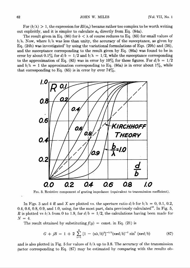
0.0 0.2 0.4 0.6 0.8 AOFig. 3. Resistive component of grating impedance (equivalent to transmission coefficient).
In Figs. 3 and 4 R and X are plotted vs. the aperture ratio d/b for b/\ — 0, 0.1, 0.2,0.4, 0.6, 0.8, 0.9, and 1.0, using, for the most part, data previously calculated10. In Fig. 5,R is plotted vs b/\ from 0 to 1.9, for d/b = 1/2, the calculations having been made forN = 4.
The result obtained by substituting f(y) = const, in Eq. (21) is
G+jB= 1 + 2 X [1 - (n\/b)2]~1/2(nird/by2 sin2 (mrd/b) (87)n = 1
and is also plotted in Fig. 5 for values of b/\ up to 3.8. The accuracy of the transmissionfactor corresponding to Eq. (87) may be estimated by comparing with the results ob-

1949] DIFFRACTION OF A PLANE WAVE THROUGH A GRATING 63
tained from the solution (84) which are accurate to better than 1% (estimated) forb/\ < 2. The accuracy of Eq. (87) will, however, improve with increasing values of b/\.
Moreover, for large values of b/\, the imaginary part of Eq. (87) may be neglected,while the real part is given approximately by
oo
G = 1 + 2 23 (nird/b)~2 sin2 (mrd/b) = 1 + (b/ird)2S(rd/b), (88)71= 1
S(x) = 23 n~* sin2 (nx). (89)
0.0 0.2 0.4 0.6 0.8Fig. 4. Reactive component of grating impedance.
Differentiating Eq. (89) with respect to x yields
= 23 n'1 sin (2nx) = Im 23 n~1 exp (j2nx)CLX n= 1 n=l
(90)= Im [In (1 - e''2*)"1] = (| " ®).
Integrating Eq. (90) with respect to x, and requiring <S(0) = 0, yields
S(x) = | (t - x). (91)

64 JOHN W. MILES [Vol. VI I, No. 1
Substituting Eq. (91) in Eq. (88) yields
Since B is negligible
0 ~ \ M
T = i - f. (93)in agreement with Kirchhoff's theory, so that Eq. (87) is certainly correct for sufficientlylarge values of b/X. Eq. (93) is borne out by Fig. 5.
1.0
0.8
0.6
0.4
02
i 1 r- From F/g. 3
From Eq. (84 a) rFROM Eq. (8 7)
K/rchhoff Theory
0.0 0.8 1.6 2.4 3.2 4.0Fig. 5. Transmission coefficient for half open grating as computed from Eqs. (84a), (87), and
Kirchhoff theory.
The value T — d/b predicted by Kirchhoff's theory is plotted in Figs. 3 and 5 forcomparison, and it is seen that the agreement is not good, even for values of b/X approach-ing 2, but is evidently satisfactory for b/X > 4. Morse and Rubenstein,16 in calculatingthe exact results for the diffraction of a normally incident plane wave on a single slit,obtained agreement for values of d/X greater than about unity. On the other hand, Morseapd Rubenstein's results show that it is necessary to go to quite large values of b/X in thecase of oblique incidence before agreement with Kirchhoff's results is obtained. Unfor-tunately, the present method cannot be applied to the problem of oblique incidence forthe grating, except perhaps in those special cases where the periodicity of the incidentwave in a plane of constant 2 is the same as the periodicity of the grating.
It is also of interest to note the sharp resonance at b/X = 1, in contrast to the slightdip at b/X = 3. There are no resonances at b/X = 2 or 4 due to the additional symmetryintroduced at d/b = 1/2.
16P. M. Morse and P. V. Rubenstein, The diffraction of waves by ribbons and slits, Phys. Rev. 54 >•895-898 (1938).