the black streak rocket project bolton science and technology
TRANSCRIPT

The Black Streak Rocket ProjectBolton Science and Technology CentreA. Dutton, J. Cropper, R. Hague, T.SteegOctober 2011Version 2.

Black Streak Rocket project
IntroductionThe project that would become Black Streak began in 2008 when Paul Abbott, director of the then Technical Innovation Centre in Bolton succeeded in securing a discretionary grant from the Northwest Development Agency. This was for an educational project to inspire students into science and engineering through rocketry. Rather than run a self contained project like the rocket building summer schools the centre had done before it was decided to attempt a project that would leave a reusable resource for schools at its culmination.The concept formed of a reusable launch vehicle for school experiments, initially to be a very large rocket (12m tall, 1m diameter) built directly with local student help and carrying as many as 100 payloads to around 1000 metres. It was intended to split into four sections to make it manageable and also to permit it to visit schools when not needed for launch preparations.While this rocket was in principle feasible the logistics of bringing students from a number of schools together for a useful period of work made construction difficult. School uptake of the existing model rocket competition, UKayRoc, indicated it was unlikely that 100 schools would contribute payloads and the logistics of transporting, assembling and retrieving such a large rocket all contributed to a change of direction.Reducing the target to ten school payloads offered the chance to design a much smaller and more practical vehicle. In addition a smaller vehicle could be built to achieve much greater speed and altitude, offering access to environments that school built rockets could not easily achieve (versus the 1000 metres of the large rocket).Initial studies centred upon a Cesaroni Pro150 motor from Canada, this would have been used in a single stage vehicle of comparable design, but greater diameter, to the final Black Streak second stage. However the Pro150 originates from a cruise missile boost motor and, for our purposes, wastes much of its power in producing a very high thrust for a very short duration. The maximum altitude simulations suggested the design could achieve was only 13,000 metres; this combined with the challenges of importing a new motor to the UK discounted this option.The largest motors currently available in the UK are the Aerotech and Cesaroni N class solid rocket motors. Simulations suggested that a two stage vehicle employing two such motors could achieve 17 to 18km altitude. The Aerotech N2000w model was chosen due to team familiarity with Aerotech products.

Vehicle designBlack Streak was thus designed to provide the minimum possible structure around the Aerotech motors and a specified payload volume. Though the motors were enclosed in the outer body tube, rather than mount a separate fin collar, for improved aerodynamics, they were positioned such that they protruded 150mm from their respective stages to act as a coupling tube. Both propulsion stages are identical and interchangeable to simplify construction and assembly.
Figures 1 and 2, CAD perspective from Autodesk Inventor and first assembly after painting.
The airframe was built by Neil Dykes of Composite Mast Technology Ltd (COMET) and is composed of carbon fibre tubes for the propulsion modules and glass fibre for the payload module and nose cone, chosen for radio transparency.The fins are of trapezoidal section and are of a glass fibre/foam core sandwich construction. They are blended and bonded directly to the outer surface of the carbon tubes. The nose cone is a three calibres long conic shape with an integral coupler.

Parachute recovery1st stageA small 28” Skyangle parachute, protected by Nomex fabric, is deployed at inertially detected apogee with a black powder charge controlled by a G-Wizz controller. This unit also ignites the second stage motor upon inertially detected 1st stage motor burn-out.2nd stageThe second stage parachutes are controlled by an RDAS flight computer, the stage is split between the motor and payload section at apogee when a black powder charge deploys a 20” drogue. The separately attached 60” Skyangle main parachute is deployed at 200 metres detected barometric altitude by a second black powder charge.
Marine landing and recoveryFrom the start of the high altitude project the intention was to go for splash down and marine recovery, given the limited space in the UK for such flights. In the interests of obtaining a proven and effective floatation system it was decided to go for water sensitive yachting life jackets. These are an inexpensive pre-existing product designed to work reliably in life saving; stripped of the extraneous hardware they packaged well into the rocket, one life jacket was paired with the 1st stage parachute and another with the 2nd stage drogue.
Figure 3, Schematic of recovery system

Launch padIn the interests of reducing drag on the rocket launch lugs were dispensed with in favour of an all encompassing launch pad. After prior experience of heavy and unwieldy steel launch pads the intention was to continue the modular design of the rocket and employ a modular, lightweight aluminium launch pad that could be stabilised, if required, by attachment to the ground rather than its sheer mass. The Bosch Rexroth extruded aluminium construction system appeared to be an effective medium for the launcher and an outline concept was designed with standard parts in mind. Four copies of a standard 1 metre module would be assembled into a 4 metre launch guide, each part being an easy two person lift over rough terrain.The local Bosch distributor for Northwest England was found to be Protronix Ltd in Glasgow. They were approached about the project and undertook to design and provide the launcher entirely as sponsorship in kind. Clark Robertson and Scott Hunter of Protronix produced a detailed design of the final launch pad, proposing further details that we had expected to have to handle in house at the centre in Bolton, by now Bolton Science and Technology Centre.The final pad is broken into three 1.3 metre modules, each formed by Bosch extrusions but joined by bespoke plates produced by Protronix themselves. All three modules include a secondary fin guide to prevent any rocket rotation within the pad, the top most unit has holes for the attachment of guy-ropes and the bottom module the adjustable legs.
Figures 4 and 5, The launchpad at Protronix and ready for launch

Launch site
A number of locations were considered for carrying out the launch.
Figure 6, prospective launch sitesCape WrathAn established military range is already in place at Cape Wrath, the UK’s most north westerly point. The potential launch point is both remote from ground structures and offers an established marine range for recovery. However the distance and remoteness of the location (20 hours and 970 miles round trip) significantly increased the logistics of the launch and risked costing too much of the grant funding.
South UistThe same was true of the established missile testing facility on South Uist, while much better served by the island communities it would involve considerable journey time and ferry travel from Bolton, separate form the consideration of if we would even receive permission to use the site. It’s worth considering that the when the Royal Aircraft Establishment were engaged in the Black Arrow programme they considered Woomera in Australia more convenient than Uist.

EskmealsAn active missile testing range is operated by Qinetiq on the Cumbrian coast above Barrow in Furness. This has suitable facilities, a large designated danger area in place, and would only be 100 miles/2 hours from Bolton. However Qinetiq were not amenable to external operators using the site.
Ailsa CraigAilsa Craig presented an interesting opportunity, it is a small island approximately 1km in diameter lying 16km from the coast of Ayrshire. This offers tremendous flexibility and control of the launch site; but the cost of marine transport to the island and for recovery of the rocket was prohibitive.
Mull of GallowayThe final launch site was found by looking for peninsulas that would retain many of the advantages of Ailsa Craig while still being attached to the UK mainland. The Mull of Galloway is unique in its combination of length and narrowness at the tip. Large peninsulas like the Mull of Kintyre tending to be broader, and therefore more populous.The Mull of Galloway extends approximately 20km south from Stranraer and culminates in a narrow eastward pointing tip, that is only connected to the rest of the peninsula by a 300m neck. It also had the advantage that it was only 4 hours from BSTC and midway between the team members in other parts of the UK.
Figure 7, Local overview of the Mull of Galloway

Figure 8, Close up of launch area
Launch site stakeholdersThe area around the tip of the Mull is owned by the Northern Lighthouse Board, so they held ultimate consent for our use of the site. They required evidence that we had consulted all parties with an interest in the area, had the relevant aviation and marine clearances and suitable insurance.As part of this consultation we spoke to the RSPB who manage the land as a sea bird reserve, Scottish Natural Heritage (SNH) who administer the adjacent Luce Bay as a Site of Special Scientific Interest, National Trust for Scotland who operate the Lighthouse cottages as holiday lets, the South Rhins Development Trust (a community organisation that are responsible for the lighthouse visitors centre) and the Gallie Craig Cafe. All of whom were satisfied with the case presented to them.
Legal approval
Aviation clearanceFollowing the increasing interest in high power rocketry in the UK around the turn of the century the UK Air Navigation Order was expanded to cover private rocketry. Vehicles below 10240Ns are considered “Small Rockets” and continue under the existing approach of responsible self governance in line with established rocketry association guidelines. Vehicles over 10240Ns are defined as “Large Rockets” and must complete a safety case with the Civil Aviation Authority (CAA).The CAA has a specified range of data that is required from large rocket applicants that they then base airspace utilisation permission upon. Their remit is the implications for air traffic, though they do take an overview of general launch safety as part of their process. As well as issuing the airspace permission they put in place the normal NOTAM procedure for the flight. The application and permission documents for Black Streak are included in Appendix C.
Marine clearanceHaving consulted SNH directly concerning landing in Luce Bay they advised us that we would need permission under the Coastal Protection Act to drop material, whether recovered or not, into the sea. This permission was handled in 2010 by the Transport Directorate of the Scottish Government, this responsibility has now passed to Marine Scotland.This process involves the consultation with Marine Scotland (environmental considerations), all relevant fisheries associations, HM Coastguard Agency and the Royal Yacht Association. Upon the advice of the Directorate we consulted directly with all these bodies prior to the request being issued by the Directorate, this enabled us to address any concerns or conditions they might have rather than respond reactively to an objection. The only requests received were to arrange a VHF voice warning in addition

to the Radio Navigation Warnings we had already planned, and to make a local broadcast to the effect from the recovery boat.As a result CPA permission was successfully attained and is attached in Appendix D.Radio Navigation Warnings/Notice to mariners was arranged with HMCGA.

SimulationFlight simulations were undertaken in two separate simulation systems, Rocsim from Apogee Components and Cambridge Rocketry Toolbox from Simon Box at the University of Cambridge.
RocsimInitial design testing and simulation was carried out with Rocsim, this is a commercial software system which enables the design and refinement of a rocket with an adjustable GUI. This immediately gives an indication of aerodynamic stability, before then allowing the design to be loaded with a motor from an incorporated or online library.Tests with a 5kg payload and 1 second ignition delay between stages predicted an apogee in the region of 17 to 18km.
Cambridge Rocketry ToolboxIn 2009 an alternative open source rocket simulator became available, Cambridge Rocketry Toolbox (CRTB) developed at Cambridge University by Simon Box. At present this is a text driven system working within Octave, an open source equivalent to Matlab, though a GUI is in development.CRTB offers a greater ability to account for environmental conditions, accepting Met Office general aviation data (F214 forms) and forecast data (.pp format). In addition it is capable of generating statistical landing scatter plots and calculating required launch inclination and direction for a given landing zone in a given wind profile.A range of simulations were carried out with varying wind data from the mid-Irish Sea wind data point, both in the course of refining the launch risk assessment and in the lead up to the launch day itself. Plots for one and two standard deviations were created for both the booster and the upper stage. These, combined with what was taken to be an over estimation of apogee due to the lack of historical calibration for rockets of this size, gave us confidence we could bring the components down in an acceptable manner for the launch site.CRTB estimated maximum altitude to be in the region of 30km, which seems excessive given the installed propulsion. Discussion with Simon Box indicated that the difference was likely due to the degree to which CRTB estimated the post-supersonic reduction in drag. We have not found if Rocsim assumes a flat supersonic coefficient of drag rather than a reducing one, or indeed if CRTB was reducing the Cd excessively. Given the installed propulsion, and the inevitable inefficiencies in the real rocket, an intermediate maximum altitude would seem a reasonable expectation.It is hoped that the Black Streak flight data will provide the means to further calibrate CRTB for rockets of this size and performance.

InsuranceWhile not a legal requirement it would be irresponsible to carry out a launch of this scale without appropriate public liability protection in place. In addition proof of a sufficient level of cover was a condition of the Northern Lighthouse Board and the RSPB for us to use the site.As the BSTC is part of Bolton Metropolitan Borough Council their administration department handled the procurement of the insurance cover. BSTC provided the internal risk assessment and a modification of the application document supplied to the CAA, including the statistical scatter plotting data, which BMBC then used in correspondence with underwriters. After some minor clarifications BSTC received a quotation that could be activated given an confirmed launch date. Initially this had been specified for a single launch time, which ran the risk of a weather postponement invalidating the insurance and leaving the project unable to afford additional cover. The terms were thus modified such that the cover was only “used up” if the launch took place or there was a launch related claim without flight.For the launch day BSTC had in place £5 million public liability cover for £2500 plus insurance tax; while this is the second largest individual cost after the vehicle itself (followed by propellant) this premium is significantly cheaper then other private launch cover the team has previous experience of. This is an very positive indication upon the safety case put to the insurers and it is hoped this can be further reduced for future launches.
Payload design by Jordan Cropper
The BSTC payload for the rocket comprised several sections which act both together and separately to log data and transmit it back to the ground station via a radio telemetry link. The payload was divided into the mbed section, which had an mbed ARM development board at its core, and the PICAXE section, based around the PICAXE series of microcontrollers.
mbed section: Hardware and softwareThe mbed section was built around the previously mentioned mbed development board. Designed and built by ARM in the UK, the mbed combines a great deal of powerful features into a small board. It has uses in industry as a powerful but compact rapid-prototyping tool, allowing engineers to develop first stage designs without having to build a specific board for every task. The mbed has also found favour with the hobbyist and 'hacker' market, and has been used in a huge variety of different applications. In this first launch of the rocket, we made little use of some of the highest level features of the mbed, such as its inbuilt ability to connect to the internet, even acting as a web server, or it's ability to connect to other such devices as part of a CAN or act as a USB host. The primary aim of the mbed section was to act as a data logger, using a variety of

sensors attached to the board via the mbed's I2C, SPI and Serial interfaces. The attached peripherals were:
SD cardAccelerometerTemperature SensorGPSPressure sensorDigital Compass
These peripherals were connected to the mbed by a PCB designed by Torben Steeg and manufactured at the BSTC. This PCB also supplied the correct power supply to each component on the board, and included backup capacitors to provide power for a limited time in case the batteries became disconnected in flight.
Time was kept by the mbed's inbuilt real-time clock. The mbed was programmed to log data from the sensors and store it on a file on the SD card. Each time the mbed was powered on, a new file was created on the SD card to avoid over-writing previous data. The program was designed to run as fast as possible, to gather the highest amount of data with the greatest resolution on the time-scale. In practice, a sample rate of between 3 and 5Hz was achieved. The main limiting factor was believed to be the GPS; all other sensors could be logged at a much higher rate. Storage size was no issue due to the SD card; the rocket launched with a 2GB SD card, which would have allowed continuous logging for several days before running out of space. A simple .csv file stored the data, which can then be read by almost any spreadsheet software package. We used OpenOffice 3.0.
The mbed section was also designed to transmit this data back down to ground via a packet radio system. To do this, a serial output stream on the mbed was connected to an Argent Systems arduino radio shield via a simple 3 wire (Tx, Rx, ground) connection. The radio shield acted as a modem, encoding the serial stream from the mbed into APRS packets. This packet data was then sent to a standard, unmodified walkie-talkie (via the microphone input jack), which transmitted it over a licence free radio band. This was picked up by a second walkie-talkie on the ground station, which was connected to a laptop computer running software to decode the APRS packets. The program contained a function that transmitted once every second.
Several other features were built into the mbed subsystem to account for different parts of the flight. A brown-out detection function in the mbed program detected if the batteries had become detached. If this happened, the system had a few seconds of run-time on the super-capacitors built into the board. If a loss of power was detected, the

mbed would immediately shut down, preserving the logged data. A section of the program was also written to allow the mbed to switch from transmitting the data stream over the radio to transmitting its latitudinal and longitudinal coordinates as it neared the end of its flight. Due to certain constraints, this part of the program was not implemented on the actual flight, but may be re-instated in the future.
mBed sensor hardware:
SD card holder; designed and built by Torben Steeg
Accelerometer: ADXL 345 using SPI interface, library from the mbed website (community code)
Temperature Sensor: DS18B20 one-wire temperature sensor. Interface code from the mbed website (community code)
GPS: LocSense LS-40EB GPS module from the PICAXE GPS board.
Pressure Sensor: Freescale MPX2100AP Absolute pressure sensor.
CMPS03 digital compass chip. Interface library from mbed website (community code)
PICAXE SectionPICAXE is a range of microcontrollers and their associated products designed and sold by Revolution-Education. They have a wide use in education, particularly in secondary schools.The PICAXE section also had a data-logging function on the flight. It was comprised of two separate boards, which shared nothing put a power supply. The first board, the 'Datalogger', stored data from its two inbuilt sensors; a temperature sensor and a light sensor. It had an expandable memory section giving it 2MB of memory, more than enough to log the flight.The second board was originally a GPS board. Due to difficulties in getting the GPS board to send data to the data-logging board to be stored, the actual GPS module was removed and became part of the mbed section. The GPS board was therefore given the job of filming the flight. A small perspex window had been cut out of the rocket, and the insides of a Flip HD video camera were mounted next in the PICAXE section. There were several headers of the board of the flip camera, allowing us to control recording using the digital outputs of the GPS board.

Launch report by Robin Hague
I arrived on site with Anthony Haynes, Malcolm Mitten and Neil Garfield just after 06.00. We went to check over the area and select the launch and control positions based upon the conditions of the day. We decided to place the pad on the last section of cliff top on the peninsular, this is above Lagvag point and slopes gently to the east. It was also decided to designate the helicopter pad as the viewing area and place the launch control point on a rock outcrop approximately 10 metres downhill towards the launch pad. The sky overhead was clear with cloud cover visible on the mainland and slight groupings apparently down wind.
Figure 9. Anthony and Neil at the launch site, from the viewing area.
We returned to the car to collect tools and met the Bolton Science & Technology Centre (BSTC) minibus at the RSPB reserve car park; Centre director Torben Steeg, leading the BSTC party in the minibus placed the bus adjacent to the RSPB visitors centre and the team unloaded the equipment.
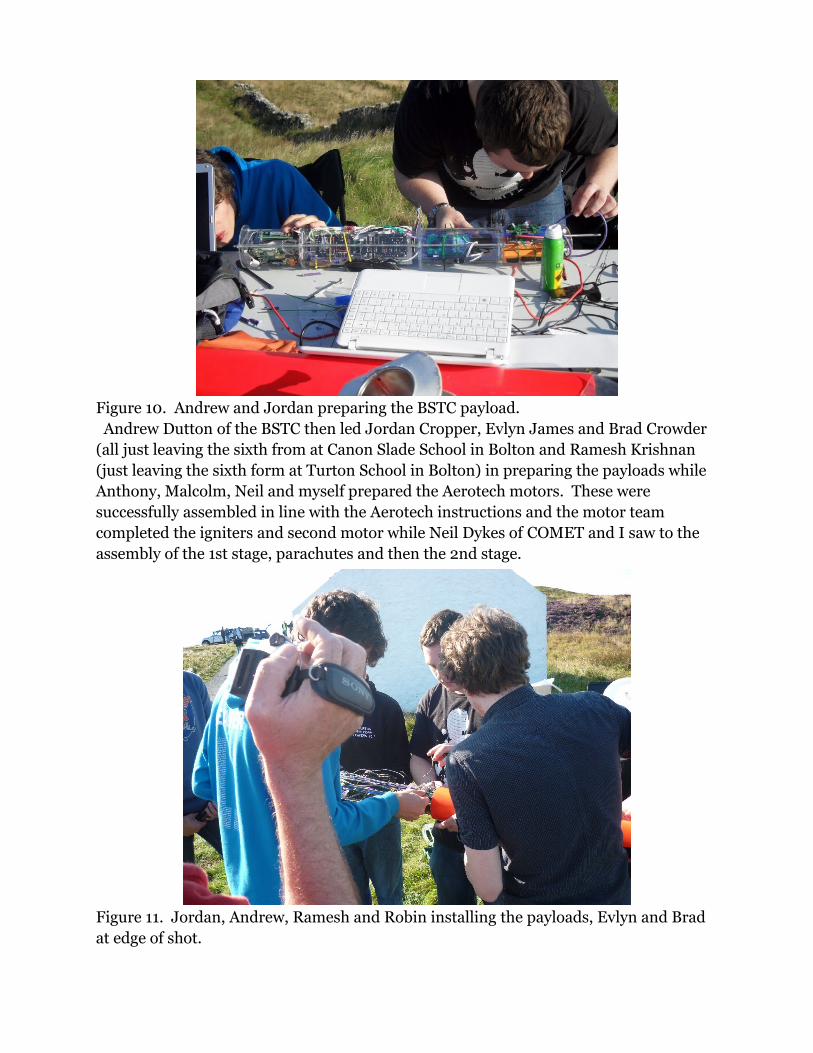
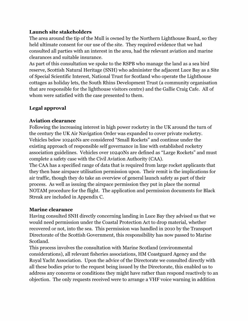
Figure 10. Andrew and Jordan preparing the BSTC payload. Andrew Dutton of the BSTC then led Jordan Cropper, Evlyn James and Brad Crowder (all just leaving the sixth from at Canon Slade School in Bolton and Ramesh Krishnan (just leaving the sixth form at Turton School in Bolton) in preparing the payloads while Anthony, Malcolm, Neil and myself prepared the Aerotech motors. These were successfully assembled in line with the Aerotech instructions and the motor team completed the igniters and second motor while Neil Dykes of COMET and I saw to the assembly of the 1st stage, parachutes and then the 2nd stage.
Figure 11. Jordan, Andrew, Ramesh and Robin installing the payloads, Evlyn and Brad at edge of shot.

Figure 12. Malcolm, Anthony, Neil Garfield and Robin preparing the propulsion modules.
The 1st stage contained one 28” Skyangle parachute, one SeaPro automatic life jacket, one G-Wizz LC400 deluxe parachute controller and one parachute charge. The G-Wizz was tasked with igniting the 2nd stage motor directly after the inertial detection of 1st stage burn-out and deploying the parachute and life jacket at apogee. The G-Wizz was prepared in a plastic tube with key switch which was intended to be slid in with the fabric components, such that the key switch was accessible through a port. This proved impractical and the switch was removed in favour of trailing twist wires. These were left fully insulated until installed in the pad.

Figure 13. Neil Dykes of COMET with payload module.
Both stages were equipped with three Daveyfire igniters sandwiched in a block of additional propellant. This was then glued together and the propellant block provided an interference fit in the motor port to support the igniters at the top of the motor. The motors were then installed in the rocket by screwing an eye-bolt through the thrust bearing bulkhead into the threaded motor cap. The slight play around the motor case was removed by shimming the motor with cartridge paper.
In the meantime the launch pad and ignition system were assembled in the horizontal position by Mark Gilbert, Angela Gilbert, Evlyn James and Brad Crowder.

Figure 14. Assembled pad ready for rocket instalation.
As they were completed all three modules were carried down to the launch site. The 2nd stage consisted of the 2nd stage propulsion module and the payload module, a 20” drogue parachute and SeaPro life jacket were packed in the top of the motor module and a 60” Skyangle main parachute was packed in the rear of the payload module. The payload module contained the experimental electronics and an RDAS rocket controller with GPS and Telemetry modules. The RDAS was intended to relay GPS data to the ground and ignite the drogue parachute charge (deploying both the drogue and the life jacket) at apogee and the main parachute charge at 200 metres barometric altitude.
The parachute charges were all identical, 2 grams of black powder contained in plastic pots over-wrapped with layers of tape and ignited by a single Daveyfire igniter. This was primarily evolved for the high altitude 2nd stage drogue parachute charge, but was used for the other two charges as an effective package. The 1st stage was connected directly to the G-Wizz, the two second stage charges were passed through the instrument bulkhead and connected to the RDAS.

The level of preparation required pushed our readiness back to just after 10.00 and an extension was granted by military ATC.
Figure 15. 1st stage being connected to the installed upper stage.The payload module and 2nd stage propulsion module were joined next to the launch pad and slid into the horizontal guide. The 2nd stage igniters were connected to the G-Wizz contacts protruding from the 1st stage propulsion module and then the 1st stage was slid (with a paper shim in place) onto the 2nd stage motor. The whole assembly was then slid into the launch pad. The launch pad was raised and in the absence of wind profile data was simply aligned to be within one degree of vertical. In the absence of a bracket to support the rocket off the ground it was lifted by the team to permit the connection of the launch control, this was done by means of a ceramic terminal block. The rocket was placed back with a screw driver to keep it off the ground, but the launch control showed no continuity. So the rocket was lifted again for disconnection.

Figure 16. Connecting the launch controller to the 1st stage.The launch control was found to have good continuity and was supplying voltage to the pad, the bulb was found to be in error. The rocket was reconnected to ground control and the G-Wizz armed with the twist wires. The RDAS had been armed before rocket elevation as it was not controlling propulsion.
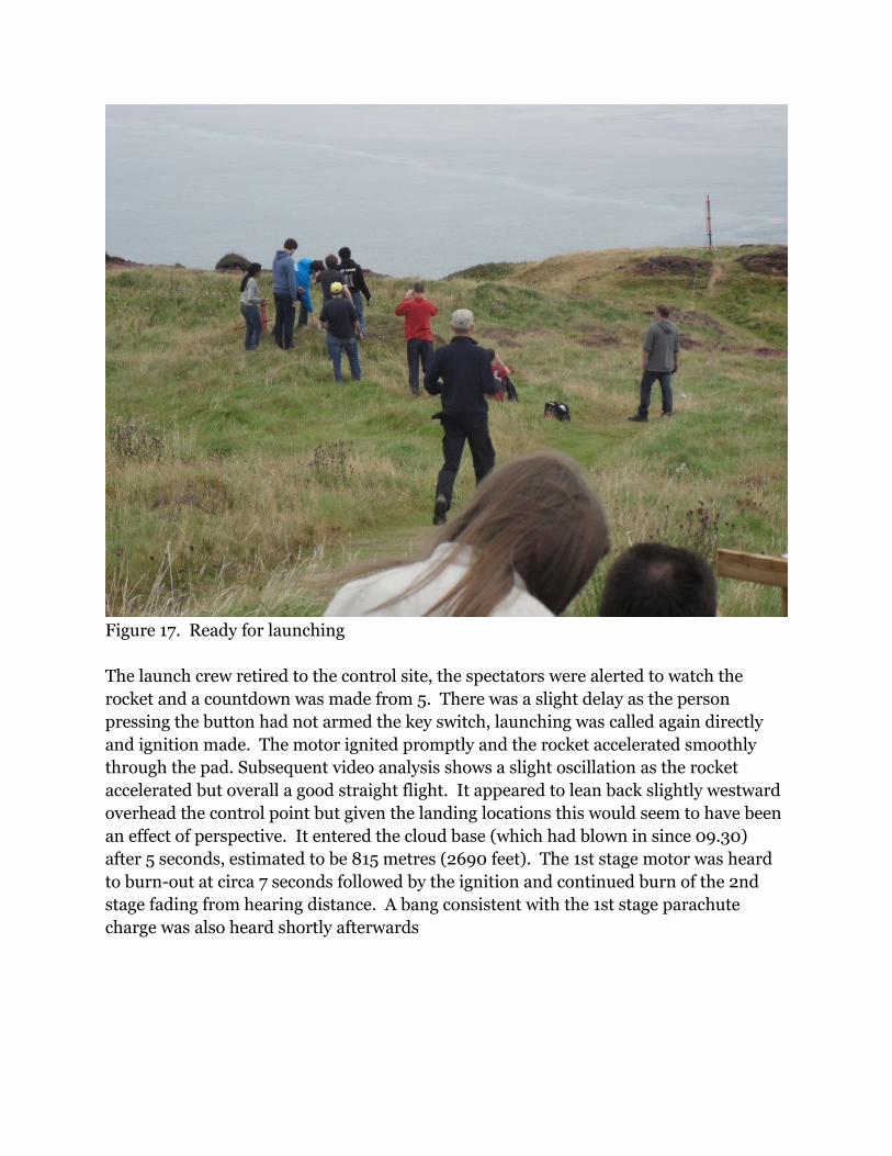
Figure 17. Ready for launching
The launch crew retired to the control site, the spectators were alerted to watch the rocket and a countdown was made from 5. There was a slight delay as the person pressing the button had not armed the key switch, launching was called again directly and ignition made. The motor ignited promptly and the rocket accelerated smoothly through the pad. Subsequent video analysis shows a slight oscillation as the rocket accelerated but overall a good straight flight. It appeared to lean back slightly westward overhead the control point but given the landing locations this would seem to have been an effect of perspective. It entered the cloud base (which had blown in since 09.30) after 5 seconds, estimated to be 815 metres (2690 feet). The 1st stage motor was heard to burn-out at circa 7 seconds followed by the ignition and continued burn of the 2nd stage fading from hearing distance. A bang consistent with the 1st stage parachute charge was also heard shortly afterwards

Figure 18. Ignition

Figure 19. Away she goes...

All spectators and crew watched for returning components and the 1st stage was seen falling into East Tarbet Bay as intended. No ballistic return air noise or impact was heard leading us to believe the 2nd stage experienced successful parachute deployment to some degree.After addressing the spectators and press the launch team proceeded to clear the site and the 1st stage was returned by the recovery boat. The life jacket had successfully functioned as an automatic floatation bag, though the parachute itself appeared to have tangled and not deployed properly. Given the relatively high design descent speed of this stage it had not significantly deviated from the expected landing point.
Figure 20. Recovered 1st stage.Approximately an hour after launch team members returning to dismantle the launch pad believed they may have seen the main parachute floating below the surface of the sea just off the headland. They hailed a private fishing boat that had watched the launch to investigate and this was found to be the 2nd stage motor floating without a floatation aid. When it was returned to the team it was found to have broken the line joining it to the payload module, and had been floating solely through air trapped in the motor casing.

Figure 21. Second stage motor module is recovered by passing fishing boat.
A simulation of the flight was carried out as soon as the Met Office general aviation wind profile for the launch period could be collected from the Met Office website. Despite the prevailing wind being southerly at ground level it was predominantly westerly above 300 metres (1000 feet). Upon running the simulation the 1st stage was predicted to land very close to the observed position. By contrast the 2nd stage was predicted to have arced eastward, deploying the main parachute and splashing down approximately 6km eastward. If the motor lanyard snapped at main parachute deployment, either due to the failure of the drogue charge or simply excessive deceleration from drogue to main, then it does not seem unreasonable that the tide could have swept the motor back to the headland in the time between launch and discovery.The 2nd stage motor was found without any life jacket or parachute implying that the payload section retained the drogue, life jacket and main parachute. This section is significantly lighter than the combine 2nd stage and would drift much further eastwards if it was on the parachute alone. The construction, and indeed the manner in which the 2nd stage motor was found, of the payload section should enable it to float even without the life jacket. Given the addition of the life jacket and the parachutes it is hoped it will

remain afloat for some considerable time and present a highly visible object likely to be recovered.
Figure22. CRTB simulation of flight with launch day wind, note 1st stage path in red.
Figure23. Post-launch pad, clean-up time.

ConclusionThe Black Streak rocket, launch pad and ignition system have been shown to work effectively. All indications are that the flight was successful but for the recovery of the second stage, and we have recovered sufficient components to enable the establishment of the schools payload design competition, should funding be available.
Proposed changesInternet access needs to be arranged in some manner to permit on site flight simulation with real wind profiles.Motors and payload should be loaded the day before, this would have happened but for unavoidable transportation delays.The launch pad requires a removable bracket to support the rocket off the ground.The orientation of the launch pad should be set without the rocket in place, the leg stops positioned for that orientation before the pad is laid down again for rocket loading.Guy ropes should be added for back-up stability.The remote launch control box should be closer to the launch pad.An interstage will be used to provide more space between the 1st and 2nd stages.Arming key switches should be fixed into the outer body.Consideration should be given to a substantial pull pin able to cope with vibration if the 2nd stage is given control of the 2nd stage motor, this would provide greater clearance for the person arming the igniters.The 2nd stage electronics should be given control of the 2nd stage motor to simplify the electronics on board, this would be accomplished by provision of an igniter connection through the motor cap.A diagnostic connection could also be made available to the outside of the rocket.A more powerful telemetry transmitter is required.A dedicated telemetry operative is required.Flexible dipoles antennas to be attached to the life jackets such that they are deployed by the inflation of the jacket, this would provide better transmissions when the rocket has splashed down.Stronger webbing to be used between the components of the second stage, possibly in two lengths so the potential breakage of the 1st length absorbs the shock for the 2nd length.Falconry transmitters as a back-up location system.

Appendix ADimensional views


Appendix BCivil Aviation Authority application and consent documentationNote application features the originally intended dates, these were rolled forward as the project extended.

ROCKET LAUNCHES
Until recently the activities of amateur rocket enthusiasts in the UK have been limited by the commercial availability of low power output of rocket motors to support this activity. To that extent, most rockets used by amateur ‘rocketeers’ were regarded as little more than ‘large fireworks’, and treated as such by other airspace users and by the regulators. However, recent developments in small rocket technology have led to much more powerful motors being available and, although still very much a minority activity, now has a much higher profile amongst the aviation community. This was recognized by the Civil Aviation Authority (CAA), and in 2001 the Air Navigation Order was amended to provide legislation to regulate the manner in which rockets were launched. The current Article1 dealing with rocket launches divides rockets into the following categories:
Small Rocket: the total impulse of the motor or combination of motors exceeds 160 Newton-seconds, but does not exceed 10240 Newton-seconds.2
Large Rocket: the total impulse of the motor or combination of motors is more than 10240 Newton-seconds.3
Rockets with a total impulse of the motor or combination of motors of less than 160 Newton-seconds remain outside the bounds of Article 99 of the Air Navigation Order, and may be regarded as fireworks for the purpose of this legislation. However, individuals operating these rockets must do so responsibly, and are still subject to that part of the Air Navigation Order that deals with Endangerment.4
Within the Directorate of Airspace Policy in the CAA, there are 2 points of contact that deal with all rocket enquiries, permissions and policy. These are Off-Route Airspace 1 (ORA1) in the Off-Route Airspace section, and Airspace Specialist 2 (AS2) in the Airspace Utilization Section (AUS). Contact details are at the end of this document.
ORA1 has responsibility for policy-making for rocket launches in the UK, and in addition provides one-off permissions for large rocket launches, as defined in the ANO.
AS2 deals with all routine one-off launches of small rockets.
When dealing with rocket launch requests the primary function of both posts is to provide advice and direction to the applicant so that he is best informed on the measures to be taken to ensure a safe rocket launch and flight. The CAA may liaise and coordinate with other airspace users to ensure that the proposed launch is given appropriate publicity amongst those agencies that need to be aware of the details of the launch. Once the date, time and location of the launch have been agreed, AUS will
1 Air Navigation Order 2005 – Part 8 Movement of Aircraft – Article 99, Regulation of Rockets.2 Air Navigation Order 2005 – Part 14 General – Article 155, Interpretation – ‘Small Rocket’.3 Air Navigation Order 2005 – Part 14 General – Article 155, Interpretation – ‘Large Rocket’.4 Air Navigation Order 2005 – Part 5 Operation of Aircraft – Article 73, Endangering safety of an aircraft.
33

facilitate the widespread promulgation of the activity to the aviation community using a NOTAM. In certain cases these may be supplemented by an Airspace Coordination Notice (ACN) or other airspace control measures if the scale of the activity warrants it.
The Directorate of Airspace Policy is responsible for regulating the airspace use aspects of the rocket launch. In addition all launch events should be compliant with HSE regulations, national and local laws and be covered by appropriate insurance. Furthermore, sponsors should ensure effective liaison with local authorities and emergency services is included in event planning.
DAP Points of Contact:
ORA 1Directorate of Airspace PolicyCAA House 45-59 KingswayLondonWC2B 6TE
Tel: 020 7453 6541Fax: 020 7453 6565
AS 2Directorate of Airspace PolicyCAA House 45-59 KingswayLondonWC2B 6TE
Tel: 020 7453 6582Fax: 020 7453 6593
Attached: Information required for Rocket Launch Notifications.
34
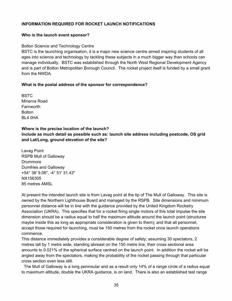
INFORMATION REQUIRED FOR ROCKET LAUNCH NOTIFICATIONS
Who is the launch event sponsor?
Bolton Science and Technology CentreBSTC is the launching organisation, it is a major new science centre aimed inspiring students of all ages into science and technology by tackling these subjects in a much bigger way than schools can manage individually. BSTC was established through the North West Regional Development Agency and is part of Bolton Metropolitan Borough Council. The rocket project itself is funded by a small grant from the NWDA.
What is the postal address of the sponsor for correspondence?
BSTCMinerva RoadFarnworthBoltonBL4 0HA
Where is the precise location of the launch?Include as much detail as possible such as: launch site address including postcode, OS grid and Lat/Long, ground elevation of the site?
Lavag PointRSPB Mull of GallowayDrummoreDumfries and Galloway+54° 38' 9.06", -4° 51' 31.43"NX15630585 metres AMSL
At present the intended launch site is from Lavag point at the tip of The Mull of Galloway. This site is owned by the Northern Lighthouse Board and managed by the RSPB. Site dimensions and minimum personnel distance will be in line with the guidance provided by the United Kingdom Rocketry Association (UKRA). This specifies that for a rocket firing single motors of this total impulse the site dimension should be a radius equal to half the maximum altitude around the launch point (structures maybe inside this as long as appropriate consideration is given to them); and that all personnel, accept those required for launching, must be 150 metres from the rocket once launch operations commence.This distance immediately provides a considerable degree of safety; assuming 30 spectators, 2 metres tall by 1 metre wide, standing abreast on the 150 metre line, their cross sectional area amounts to 0.021% of the spherical surface centred on the launch point. In addition the rocket will be angled away from the spectators, making the probability of the rocket passing through that particular cross section even less still. The Mull of Galloway is a long peninsular and as a result only 14% of a range circle of a radius equal to maximum altitude, double the UKRA guidance, is on land. There is also an established test range
35

in Luce Bay and a long history of projectile testing. RSPB have given permission to fly subject to NLB approval.
Will any relevant pre-launch testing be required?NoWho is an appropriate point of contact during the operation?Include name, mobile or on-site telephone number.
Robin Hague
Torben Steeg
Michael Radcliffe
What is the date of the proposed launch?27/03/10
What time is the launch expected to take place?0900
Are there any back-up dates or times in case the launch is delayed?03/07/10
Is any form of control or guidance system used to control the ascent of the rocket? Passive aerodynamic stability by fins
What is the maximum height to which the rocket will climb?17567 Metres
To what degree of accuracy can this be predicted?1 Sigma (68% of likely apogee values) = ± 211.64 metres of Apogee
What is the total duration of the climb and descent of the system?376 seconds
36

What is the predicted flight profile of the rocket?Within what radius of the launch site do you expect the activity to take place?Taking into account any drift during the rocket’s climb and descent.
Figure 1. 3 dimensional plot of successful flight profile
Figure 2. 3 dimensional plot of successful flight profile
37

**Mean booster stage data**:Burn out 7.68 seconds after launchApogee data:Apogee reached 26 seconds after launchApogee location is 273m West and 405m South of launch locationApogee altitude is 4490mLanding data:Landing occurred 151 seconds after launchLanding location is 460m East and 450m North of launch location
**Mean upper stage data**:Ignition and separation 8.68 seconds after launchBurn out 16.36 seconds after launchApogee data:Apogee reached 58 seconds after launchApogee location is 818m West and 1831m South of launch locationApogee altitude is 17576mLanding data:Landing occurred 376 seconds after launchLanding location is 2199m East and 275m North of launch location
38

Figure3. 1 and 2 standard deviations of ballistic return (i.e. complete failure of recovery systems
Figure 4. Close up of 1 and 2 standard deviation of ballistic failure
Figure 5. 1 and 2 standard deviation of successful flight
39

What are the weather limitations that will restrict the operation of the rocket?Include minimum cloud cover, visibility and/or wind speed.20mph ground, general aviation aircraft visibility (0 to 1000 metres)
Will precipitation or outside air temperature have an effect on the ability to launch the rocket or on the accuracy of the radius and height of the operation?Only where it impacts visibility
How you will ensure that no other airspace users are in the immediate vicinity of the launch?NOTAM, visual checking and ATC contact
Is a tracking system in place if visual tracking of the rocket is lost or is not possible?Telemetry of on-board GPS tracking
What systems for destroying the rocket or ensuring a safe recovery in the event of a malfunction?None
In addition to the above questions it would also be useful to provide at the relevant stage:
Provide technical specifications of the Rocket such as: length of the system, launch mass, payload, propulsion, total impulse, max velocity, max altitude attainable, burn duration, recovery system, time to apogee.Brief description of the operation.Provide any relevant attachments such as maps, diagrams and details of control measures.
Launch vehicleThe rocket is currently planned to be 100mm in diameter, 4 metres long and with a launch mass of 30kg and a recovery mass of 15kg. It consists of two stages and has been design around two commercially available Aerotech N2000W reloadable solid rocket motors.The rocket body will be constructed from commercially available carbon fibre composite rocket tubes. There will be three stabilising fins bonded directly to the rocket body; these will be constructed from laminated carbon fibre.All parts will be recovered by parachute and all recovery events will be controlled by well proven commercially available flight controllers. The primary controller will be an RDAS system from AED electronics in the Netherlands; this system will also transmit live GPS position and pressure altitude data through out the flight, allowing the live tracking of the flight path.The design of the rocket will no doubt be subject to some minor variations during construction but it will conform to this summary
Launch and Flight The 1st stage rocket motor will be ignited remotely by commercially available electric igniters, themselves controlled by an ignition box equipped with a secured key switch cut-out.
40

The rocket is aerodynamically stabilised, as such it will be stabilised by a fixed launch guide rail until it has reached minimum flight speed. It is calculated to reach this speed at 1.5 metres height and the launch guide will have additional length at 4 metres.The flight profile will no doubt vary slightly with final design changes but at present the sequence is:0 seconds ignition7.68 seconds 1st stage burn out, rocket coasts onwards8.68 seconds 2nd stage ignition causing stage separation at approximately 10,000 metres
altitude, 1st stage coasts on to its maximum altitude when a timer deploys a minimum diameter parachute
16.36 seconds 2nd stage motor burns out, rocket coasts onwards58 seconds 2nd stage reaches maximum altitude, approximately 17576 metres, flight
controller deploys minimum diameter drogue parachute, rapid controlled descent minimises horizontal driftMain parachute deployed by controller at 100 metres
376 seconds Soft landing of second stage
Specifications of commercially available primary systems2 Aerotech RMS-N2000W rocket motorsAeroTech Consumer Aerospace Division RCS Rocket Motor Components, Inc.2113 W. 850 N. StreetCedar City, UT USAhttp://www.aerotech-rocketry.com/ Propellant: Ammonium perchlorate/HTPB composite propellant 7.7 kg/motorUN number 0275 class 1.3CAerotech statement on reliabilityThe N2000W motor was entered into service approximately June of 1997, duringthis time span approximately 170 motor reloads have been produced. Therewere approximately 4 motors not included in the above, as these were R&D and2 motors for TRA certification.
The N2000W has been very reliable, known failures amount to approximately 2 motors. Known failures are those submitted to Aerotech for warranty replacement. The underlying cause of these motor failures was attributable to the design/manufacture process of the nozzle. Seventy five percent of the manufactured motors were used with the above mentioned nozzle without incident. As a result of other motor failures using the same nozzle (M2400T in particular), a design change was made to the nozzle to remove this possibility; the new nozzles have not experienced any problems.All in all our High Power rocket motor line has a less than a 2% failure rate on allmotors manufactured.
Flight controllerRDAS with GPS and telemetry add-onsAED electronicsNetherlandshttp://www.aedelectronics.nl/index.htm
41

42

43

44

45
46

47

Appendix CCoastal protection act application, notice and consent.As can be seen in the documentation below, the original consent expired at 23.59 on the launch day itself; however a further 12 months permission was already in place should the launch have been delayed.
COAST PROTECTION ACT 1949
SECTION 34 CONSENT
Application Form for a Scientific/Marine Study
Please complete this form in full. Please enclose copies of all relevant plans, drawings and other documentation with this application. Please enclose a copy of the relevant Admiralty chart with the location of the study clearly marked. Please provide any technical information that may be relevant to the navigational safety of the site. If applying for more than one site, please complete a separate application form for each site.
You are asked to provide the charted positions of the study. Positions should be stated in degrees minutes and decimals of minutes to three places i.e. 55°55’·555N 5°55’·555W (WGS84) and the datum should be stated explicitly. It is important that the correct positions are included with this application, as any errors may result in the application being refused or delayed.
Submitting an Application
The application form and any attachments can be e-mailed to the following address:
Alternatively you can post a hard-copy or electronic version (on floppy disk or CD) to the following address:
Marine Scotland – Licensing Operations Team, Marine Laboratory, PO Box 101, 375 Victoria Road, Aberdeen AB11 9DB
48

If submitting an electronic version by e-mail, on a floppy disk or CD, please ensure that the application form and all attachments are submitted in plain text, Word or pdf format. A signature is not required if submitting your application electronically.
If you require further assistance or advice please e-mail [email protected] or telephone 01224 295579
49

1. Applicant’s Details
Name/Organisation
R H A G U E B S T C
Correspondence Address
B O L T O N S C I E N C E & T E C H N O L OG Y C E N T R E , M I N E R V A R DB O L T O N
Post Code B L 4 0 H A
Telephone Number
Name of individual/organisation to be identified on consent form (if different from above)
2. Application Type
2.1 Is this a new application or a renewal/amendment of an existing consent? (please tick)
New application Renewal/Amendment
2.2 If applying for a renewal or amendment please enclose a copy of the original consent letter with this application or provide the consent reference number, and provide details of the amendments to be made to the consent.
2.3 Geographical location of the study:
Sol way Firth adjacent to the Mull of Galloway
2.4 Please tick one of the boxes below which best describes the proposal.
Geotechnical Survey Waveriders
Last Updated June 2010

Other (please specify) Water recovery of educational rocket2.5 Brief outline and purpose of the study:
Bolton Science and Technology Centre, funded by the NWDA, are developing a reusable research rocket for carrying high school developed experiments. We hope to launch from Lavag Point at the tip of the Mull of Galloway, soft land the rocket by parachute in the adjacent coastal waters and recover all parts from the sea for examination and reuse.
2.6 Please confirm if you have consulted with any of the following organisations listed below prior to submitting this application by ticking the relevant box. A copy of any relevant correspondence should be included with this application.
Crown Estate
Marine Scotland (Marine Laboratory) Please quote reference of any FEPA licence
Application
Maritime and Coastguard AgencyHave arranged appropriate navigational warnings
Northern Lighthouse Board Land owners of the proposed launch site
Scottish Environment Protection Agency
Scottish Natural HeritageIn relation to the Luce Bay SSSI
Other (please specify)RSPB as managers of the land where the proposed launch site is locatedCAA with regards air traffic hazard and suitable aviation warningsNTS as managers of the lighthouse buildingsLocal community, operating visitors centre and caféMCA, NLB, SNH, RSPB, CAA, NTS, and local groups have all given approval.
Further to consultation with Clyde Fishermen’s Association a VHF announcement will be made prior to launch, so as to inform vessels in the area and back up the navigational warning.
2.7 Please provide the positions of the study in the table below. Corner positions relevant to the area enclosing the study area should be provided. For buoys or other single devices the centre position should be given.
Last Updated June 2010

LATITUDE LONGITUDE1 Corner Positions
5 4 ° 4 4 ‘. 1 1 6 7 0 4 ° 5 6 ‘. 9 6 3 75 4 ° 4 4 ‘. 1 1 6 7 0 4 ° 3 7 ‘. 7 6 3 75 4 ° 3 0 ‘. 0 9 2 3 0 4 ° 5 6 ‘. 9 6 3 75 4 ° 3 0 ‘. 0 9 2 3 0 4 ° 3 7 ‘. 7 6 3 7
2 Launch site, Lavag Point. Mull of Galloway5 4 ° 3 8 ‘. 1 5 1 0 0 4 ° 5 1 ‘. 5 2 3 8
° ‘. ° ‘.° ‘. ° ‘.° ‘. ° ‘.
2.8 Expected duration of the study: 2 hours (vehicle in flight for a maximum of 6 minutes
From: 09.00 on TBC launch day To:11.00 on TBC launch day
3. Check List and Declaration
Please ensure that the following documents are enclosed with your application:
The application form Included
A copy of all relevant plans and drawings Included
A copy of the extract from the relevant Admiralty chart Included
A copy of all other relevant documentation Included
A copy of the original consent letter (if applicable) Included
I certify that the information given on this form and on any attachments enclosed is true and accurate at the time of making this application.
SIGNED:
NAME IN BLOCK CAPITALS:
DATE:
Last Updated June 2010

Notice of marine activity posted in the most significant local paper, as required by the CPA process.
COAST PROTECTION ACT 1949EDUCATIONAL ROCKET LAUNCH: MULL OF GALLOWAY
Notice is hereby given that Robin Hague, for Bolton Science and Technology Centre (BSTC) has applied to the Scottish Ministers of the Scottish Government, under section 34 of the Coast Protection Act 1949, as amended by section 36 of the Merchant Shipping Act 1988, in respect of the launch and recovery of a research rocket for educational purposes at Mull of Galloway:
Description Latitude LongitudeLaunch site: Lavag Point 54 38.151N 04 51.523WRecovery site: corner 1 54 44.116N 04 56.963WRecovery site: corner 2 54 44.116N 04 37.763WRecovery site: corner 3 54 30.092N 04 56.963WRecovery site: corner 4 54 30.092N 04 37.763W
(WGS84)
Plans showing the position of the works may be inspected at The Gallie Craig Coffee House, Mull of Galloway, Drummore, Stranraer, Dumfries and Galloway, DG9 9HP.
Objections relating to safety of navigation in respect of the application should be made in writing to:
Gordon Hastie, The Scottish Government, Ports and Harbours Branch, Area 2G North, Victoria Quay, Edinburgh, EH6 6QQ within 28 days of the date of this notice quoting reference:
2SPC\4\2\7
Robin Hague Bolton Science and Technology CentreMinerva RoadBolton
T: +44 (0)131 E: @scotland.gsi.gov.uk
R Hague Bolton Science & Technology CentreMinerva RoadBoltonBL4 0HA
___
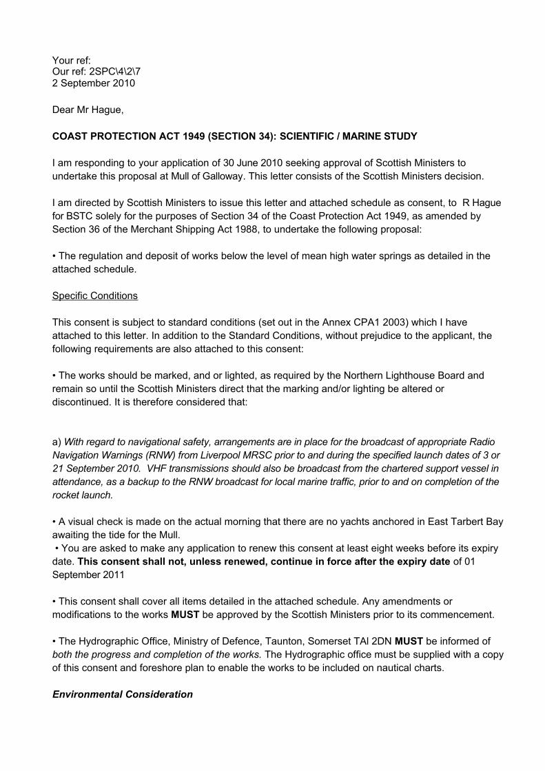
Your ref:Our ref: 2SPC\4\2\72 September 2010
Dear Mr Hague,
COAST PROTECTION ACT 1949 (SECTION 34): SCIENTIFIC / MARINE STUDY
I am responding to your application of 30 June 2010 seeking approval of Scottish Ministers to undertake this proposal at Mull of Galloway. This letter consists of the Scottish Ministers decision.
I am directed by Scottish Ministers to issue this letter and attached schedule as consent, to R Hague for BSTC solely for the purposes of Section 34 of the Coast Protection Act 1949, as amended by Section 36 of the Merchant Shipping Act 1988, to undertake the following proposal:
• The regulation and deposit of works below the level of mean high water springs as detailed in theattached schedule.
Specific Conditions
This consent is subject to standard conditions (set out in the Annex CPA1 2003) which I have attached to this letter. In addition to the Standard Conditions, without prejudice to the applicant, the following requirements are also attached to this consent:
• The works should be marked, and or lighted, as required by the Northern Lighthouse Board and remain so until the Scottish Ministers direct that the marking and/or lighting be altered or discontinued. It is therefore considered that:
a) With regard to navigational safety, arrangements are in place for the broadcast of appropriate Radio Navigation Warnings (RNW) from Liverpool MRSC prior to and during the specified launch dates of 3 or 21 September 2010. VHF transmissions should also be broadcast from the chartered support vessel in attendance, as a backup to the RNW broadcast for local marine traffic, prior to and on completion of the rocket launch.
• A visual check is made on the actual morning that there are no yachts anchored in East Tarbert Bay awaiting the tide for the Mull. • You are asked to make any application to renew this consent at least eight weeks before its expiry date. This consent shall not, unless renewed, continue in force after the expiry date of 01 September 2011
• This consent shall cover all items detailed in the attached schedule. Any amendments or modifications to the works MUST be approved by the Scottish Ministers prior to its commencement.
• The Hydrographic Office, Ministry of Defence, Taunton, Somerset TAl 2DN MUST be informed of both the progress and completion of the works. The Hydrographic office must be supplied with a copy of this consent and foreshore plan to enable the works to be included on nautical charts.
Environmental Consideration

The Scottish Government as competent authority under regulation 48 of the Conservation (Natural Habitats,&c) regulations 1994, has a duty to:
• Determine whether the proposal is directly connected with or necessary to site management forconservation, and, if not,
• Determine whether the proposal is likely to have significant effect on the site either individually or incombination with other plans or projects; and, if so, then
• Make an appropriate assessment of the implications (of the proposal) for the site in view of that site's conservation objectives.
Following this determination and from guidance received from Scottish Natural Heritage, the following environmental conditions must also be met:
a) none required
You should satisfy yourself that you have obtained any other necessary powers to undertake the works.
You should inform this Department if these works are removed before this consent expires. You should also notify this Department of any change in your name, address, ownership or modifications to the proposal to ensure the consent's validity.
Yours sincerely
Val FergusonPolicy Executive
Conditions CPA1 2003
SECTION 34, COAST PROTECTION ACT 1949.STANDARD CONDITIONS OF CONSENT
1. The works should be marked and/or lighted as required by the Northern Lighthouse Board and themarking to be continued unless and until the Scottish Ministers rescind this direction.2. If it is desired to display any marks or lights not required by this consent then details must be submitted to the Northern Lighthouse Board and their ruling complied with. The display of unauthorised marks or lights is prohibited.3. The works shall be maintained at all times in good repair.4. No deviation from the schedule specified in the consent shall be made without the further written consent of the Scottish Executive.5. No radio beacon or radar beacon operating in the Marine frequency bands shall be installed or used on the Works without the prior written approval of the Scottish Ministers.6. If in the opinion of the Scottish Ministers the assistance of a Government Department, including the broadcast of navigational warnings, is required to deal with any emergency arising from:a) the failure to mark and light the works as required by the consentb) the maintenance of the works

c) the drifting or wreck of the works,The owner of the Works shall be liable for any expenses incurred in securing such assistance.7. In the event of the consented operations being dis-continued the works shall be removed and the site cleared to the satisfaction of the Scottish Ministers.8. Officers of HM Coastguard, or any other person authorised by the Scottish Ministers, should be permitted to inspect the works at any reasonable time.9. Would you please inform this Department and the lighting authority when the works have beencompleted and the marking established.The Scottish Government
Coast Protection Act 1949: Schedule of ConsentConsent Reference: 2SPC\4\2\7
This schedule denotes all equipment and their approximate positions given in Latitude and Longitude for the aforesaid proposal. This schedule MUST be accompanied by the formal letter of consent to ensure its validity. In any instance of modification, change of ownership or removal or works this schedule should be returned to the Scottish Government with the nature of the change clearly indicated
Works positions.* WGS 84 datum
(educational rocket launch and recovery operations)Description Latitude LongitudeLaunch site 54 38.150N 04 51.523W
Recovery site: 1 54 44.116N 04 56.963WRecovery site: 2 54 44.116N 04 37.763WRecovery site: 3 54 30.092N 04 56.963WRecovery site: 4 54 30.092N 04 37.763W

Appendix DWrite-up on Rocketeers.co.uk
We arrived on site just after 06.00 and checked over the location. The Mull is a very thin peninsular stretching down from the port of Stranraer, the end portion is very nearly a small island and Scotland's most southerly point. We set up the launch pad (a brilliant lightweight affair built for us by Protronix in Glasgow) on the last bit of level ground before the cliffs.We set-to assembling the rocket back at the control point by the Stevenson's Lighthouse, with the BSTC students carrying out the final touches to their experimental payloads. The Aerotech motors went together very easily and we integrated the the two propulsion modules and the instrument module horizontally in the launch pad before raising the whole assembly (if it's good enough for Soyuz and SpaceX it's good enough for us!)We'd intended to launch between 09.00 and 09.30, but transport delays the day before meant the amount of preparation we had to do on the morning pushed back to about 10.15. Our liaison with military ATC thankfully granted us an extension and we retired to a safe distance... to find the controller was showing no continuity light. We disarmed, checked the control lead was supplying voltage (we'd previously checked the igniters before installation) and concluded it was the bulb at fault!We reset the connections and retired again, alert the spectators to be ready and on their feet and counted down from 5. Upon 0 the rocket didn't go, but the team member pressing the button hadn't armed the box. So he did, we called "launching" again and it lit...It leapt off the pad and climbed consistently with only a slight oscillation in the early stages. It appeared to arc back slightly over the control point, but upon further study it would seem this was probably simply the perspective of its climb. It quickly punched into the clouds that had unfortunately obscured the clear sky we would have had at 09.00. Very shortly afterwards we heard the 1st stage burn out and the 2nd light.Everyone watched in the direction it appeared to be heading, seconds passed with no ballistic return and then someone spotted the 1st stage drop through the clouds and land in the adjacent bay. But no sign of the 2nd stage. The recovery boat collected the 1st stage, its life jacket float bag worked perfectly, and we set about tidying the site.About an hour later some of the team went down to the point to disassemble the launch pad. One of them thought he could see what was possibly a parachute floating under the surface and hailed a private fishing boat that had come over after seeing the launch. He found it was the 2nd stage motor floating by itself, with out a life jacket. This is an aluminium and carbon fibre tube but it must have trapped enough air in the motor to stay afloat. When it was brought round to us we found the lanyard joining it to the instrument module had snapped. We'd used a small high altitude drogue followed by a main chute at only 200 metres so it would appear the heavier motor section snapped off and fell onward when the big chute deployed. This means the much lighter instrument section would have the full chute and the life jacket It would have drifted much further but could well stay afloat for quite sometime.The instrument module was carrying two independent recording systems and a Flip video camera, all recording to flash memory. So if someone does find it we stand a good chance of finding how the flight performed. A simulation done with the wind profile for the day (we had planned to use this for targeting but couldn't get mobile web on-site) gave a consistent position for the faster falling 1st stage. It also suggested the 2nd stage was carried further east than expected and if the motor dropped off at the predicted parachute deployment

position it was reasonable for it to be carried back to the Mull by the rapid tides in the area. If this is the case the instrument module would have been blown further east still towards Dumfries.Overall the rocket performed well, and as far as we can infer without the electronics it flew according to plan until main parachute deployment. There is a video of the flight on BBC online , actually provided by one of the team after the BBC had zoomed in too close to follow the rocket.And some excellent pictures taken by the RSPB wardens at the Mull (it's a sea bird reserve).