the australian battery guide - smart energy · battery accommodation ( cooli ng, ventil ation,...
TRANSCRIPT

ESC 5000.2016
The Australian Battery Guide
Energy Storage Council (ESC)
The Australian Battery Guide
Guide for Energy Storage Systems (sales, design, installation and stewardship)
Revision 0.9 May 2016
Document Number: 003
Copyright and published by Energy Storage Council, ACT, Australia 2016 Author: Peter Cockburn
Release Notes: Revision 0.9 - High level overview of The Australian Battery Guide. The ESC have released this revision to actively seek feedback and comment for a rapid release of Revision 1.0.
Guide for ESS Installation - Revision 0.9 May 2016 Page 3 of 36 Copyright 2016
PREFACE
This guide, prepared by the Australian Energy Storage Council (ESC), is an easy to understand framework designed to provide guidance to the energy storage industry and consumers in the interim while formal Australian Standards and being developed for the sector. Industry leading companies are committed to the highest levels of safety and performance. Together with consumers and other stakeholders the industry is actively involved in creating ‘worlds best practice’ when it comes to producing, selling, using and disposing of energy storage products. Together we have a shared responsibility to mange energy storage products and materials to reduce their impact on the environment and manage any risks they may pose to human health and safety. Over the last few years battery technology has undergone rapid change with a range of new chemistries being developed. It is no longer practical to dedicate a standard to a single battery chemistry. A new approach is required to accommodate the wide variety of battery chemistry under a single design and installation guide. Lithium-ion based batteries are quickly gaining market share in this sector. As such we have carefully considered the appropriate management required for this class of batteries in this guide. That said, this guide is designed to grow and be enhanced, augmented and updated to be applicable to all emerging ESS technologies. This approach to provide ‘just in time’ expert advice is focused in the first instance at identifying areas where the current understanding is lacking and additional work is required to maintain system safety. Feedback and comment on this guide is always welcome.
Guide for ESS Installation - Revision 0.9 May 2016 Page 4 of 36 Copyright 2016
CONTENTS
1 SCOPE & GENERAL .................................................................................................. 6 1.1 SCOPE ................................................................................................................ 6 1.2 REFERENCED DOCUMENTS ............................................................................ 6 1.3 DEFINITIONS ...................................................................................................... 7 1.4 ESS Installation Types ........................................................................................ 8
1.4.1 UPS ............................................................................................................. 8 1.4.2 GRID HYBRID ............................................................................................. 8 1.4.3 OFF-GRID ................................................................................................... 9 1.4.4 Other ESS Functions ................................................................................. 10 1.4.5 Renewable Output Variation Mitigation .................................................... 13
2 Energy & Power Assessment .................................................................................. 13 3 Specifying — Energy Storage System Performance ............................................... 15 4 System Configuration .............................................................................................. 16
4.1 UPS .................................................................................................................. 16 4.2 ESS T Configuration ......................................................................................... 19 4.3 ESS Critical Loads ............................................................................................ 21 4.4 ESS Off Grid (Stand Alone Power System) ...................................................... 22
5 Selection of Battery Technology ............................................................................. 23 5.1 General ............................................................................................................. 23 5.2 Safety Data Sheet (SDS) ................................................................................... 23
5.2.1 SDS - Key Information Areas .................................................................... 24 6 Hazards associated with batteries .......................................................................... 25 7 Battery Classification ............................................................................................... 25
7.1 Category 1 - Un-defined ................................................................................... 26 7.2 Category 2 - Explosive Atmospheres ............................................................... 26 7.3 Category 3 - High Temperature ........................................................................ 26 7.4 Category 4 - Toxic Atmospheres ..................................................................... 26 7.5 Category 5 - Hazardous Spills .......................................................................... 26 7.6 Category 6 - Corrosive ..................................................................................... 26 7.7 Category 7 - Inert ............................................................................................. 27
8 Battery Accommodation ......................................................................................... 27 9 Battery Enclosure Requirements ............................................................................. 27
9.1 Enclosure Categories ....................................................................................... 28 9.1.1 Category 1 - Un-defined ........................................................................... 28 9.1.2 Category 2 - Explosive Atmospheres ....................................................... 28 9.1.3 Category 3 - High Temperature ................................................................ 28 9.1.4 Category 4 - Toxic Atmospheres .............................................................. 28 9.1.5 Category 5 - Hazardous Spills .................................................................. 28 9.1.6 Category 6 - Corrosive .............................................................................. 28 9.1.7 Category 7 - Inert ...................................................................................... 28
9.2 Enclosure - Egress and Access ........................................................................ 28 10 Battery Room Requirements ................................................................................ 29 11 Installation ............................................................................................................ 29 12 Labelling ............................................................................................................... 30
12.1 FIRE EMERGENCY SERVICES INFORMATION ........................................... 30 12.1.1 Warning sign Battery ............................................................................. 31 12.1.2 ESS Sign Overview - Example .............................................................. 31
13 Documentation ..................................................................................................... 32 14 Commissioning ..................................................................................................... 32 15 Maintenance ......................................................................................................... 33 16 Stewardship ......................................................................................................... 33 17 Australian Standards ............................................................................................ 34
Guide for ESS Installation - Revision 0.9 May 2016 Page 5 of 36 Copyright 2016
FIGURES Figure 1 - ESS SCOPE ...................................................................................................... 6 Figure 2 - UPS ESS SYSTEM ............................................................................................ 8 Figure 3 - AC GRID HYBRID ESS BLOCK DIAGRAM ....................................................... 8 Figure 4 - DC GRID HYBRID ESS BLOCK DIAGRAM ....................................................... 9 Figure 5 - OFF-GRID ESS BLOCK DIAGRAM ................................................................... 9 Figure 6 - LOAD SHIFTING ............................................................................................. 10 Figure 7 - TARIFF OPTIMISATION .................................................................................. 11 Figure 8 - PEAK LOPPING .............................................................................................. 12 Figure 9 - EXPORT LIMITING .......................................................................................... 12 Figure 10 - NETWORK SUPPORT ................................................................................... 13 Figure 11 - ENERGY ASSESSMENT ............................................................................... 14 Figure 12 - ENERGY & POWER ASSESSMENT .............................................................. 14 Figure 13 - ESS SYSTEMS NOT EQUAL ........................................................................ 15 Figure 14 - UPS (STANDBY) - LAYOUT EXAMPLE ......................................................... 17 Figure 15 - UPS (ESS), WITH RENEWABLE - LAYOUT EXAMPLE ................................. 18 Figure 16 - ESS T CONFIGURATION - LAYOUT EXAMPLE ........................................... 19 Figure 17 - ESS DC TO DC - LAYOUT EXAMPLE ........................................................... 20 Figure 18 - CRITICAL LOADS - LAYOUT EXAMPLE ....................................................... 21 Figure 19 - ENCLOSURE REQUIREMENTS FLOW CHART ............................................ 26 Figure 20 - BATTERY SIGN ............................................................................................. 31 Figure 21 - ESS SIGNAGE OVERVIEW ........................................................................... 32
TABLES Table 1 - SDS KEY INFORMATION AREAS .................................................................... 24
EQUATIONS Equation 1 - TOTAL ENERGY THROUGHPUT (MWh) ...................................................... 7
Guide for ESS Installation - Revision 0.9 May 2016 Page 6 of 36 Copyright 2016
1 SCOPE & GENERAL
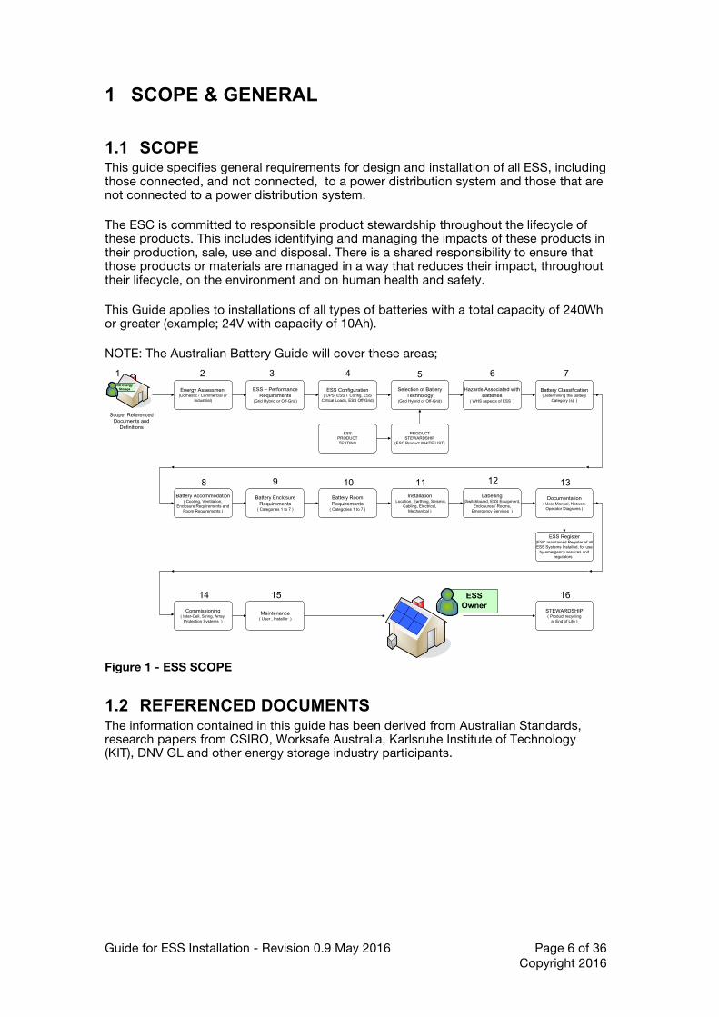
1.1 SCOPE This guide specifies general requirements for design and installation of all ESS, including those connected, and not connected, to a power distribution system and those that are not connected to a power distribution system. The ESC is committed to responsible product stewardship throughout the lifecycle of these products. This includes identifying and managing the impacts of these products in their production, sale, use and disposal. There is a shared responsibility to ensure that those products or materials are managed in a way that reduces their impact, throughout their lifecycle, on the environment and on human health and safety. This Guide applies to installations of all types of batteries with a total capacity of 240Wh or greater (example; 24V with capacity of 10Ah). NOTE: The Australian Battery Guide will cover these areas;
Energy Assessment(Domestic / Commercial or
Industrial)
NO Energy Storage ESS – Performance
Requirements(Grid Hybrid or Off-Grid)
Selection of Battery Technology
(Grid Hybrid or Off-Grid)
1 2 3
Battery Classification(Determining the Battery
Category (s) )
4
Hazards Associated with Batteries
( WHS aspects of ESS )
5
Scope, Referenced Documents and
Definitions
6
Battery Accommodation( Cooling, Ventilation,
Enclosure Requirements and Room Requirements )
7
ESS Configuration( UPS, ESS T Config, ESS
Critical Loads, ESS Off-Grid)
8
Battery Enclosure Requirements
( Categories 1 to 7 )
9
Battery Room Requirements
( Categories 1 to 7 )
10Installation
( Location, Earthing, Seismic, Cabling, Electrical,
Mechanical )
11Labelling
(Switchboard, ESS Equipment, Enclosures / Rooms,
Emergency Services )
12
Documentation( User Manual, Network
Operator Diagrams )
13
Commissioning( Inter-Cell, String, Array,
Protection Systems )
14
Maintenance( User , Installer )
15 ESS Owner
PRODUCTSTEWARDSHIP
(ESC Product WHITE LIST)
ESSPRODUCTTESTING
STEWARDSHIP( Product recycling
at End of Life )
16
ESS Register(ESC maintained Register of all ESS Systems Installed, for use
by emergency services and regulators )
Figure 1 - ESS SCOPE
1.2 REFERENCED DOCUMENTS The information contained in this guide has been derived from Australian Standards, research papers from CSIRO, Worksafe Australia, Karlsruhe Institute of Technology (KIT), DNV GL and other energy storage industry participants.

Guide for ESS Installation - Revision 0.9 May 2016 Page 7 of 36 Copyright 2016
1.3 DEFINITIONS For the purpose of this guide, the definitions below apply.
1.3.1. Energy Storage System (ESS) — combination of convertors, switches (for example multi-mode inverters) and energy storage devices (for example, batteries), constituting a power system that supports the load or for maintaining continuity of load power in case of input power failure or as the primary source of power. The energy may flow from input to output, output to input or a combination of both.
1.3.2. Grid — the portion of the electrical distribution system that is operated by an electrical distributor.
NOTE: An alternative term for ‘grid’ is ‘electricity distribution network’.
1.3.3. Multiple Mode Inverter (MMI) — An inverter that operates in more than one mode, for example having grid-interactive functionality when grid voltage is present and stand-alone functionality when the grid is de-energized or disconnected.
NOTES:
1 Inverters with battery storage ports are also considered multiple mode inverters.
2 As defined in IEC 62109-2, Clause 3.107.
1.3.4. Safety Data Sheet (SDS) — previously called a Material Safety Data Sheet (MSDS), is a document that provides information on the properties of hazardous chemicals and how they affect health and safety in the workplace.
1.3.5. Stand-alone Power System (SPS) — Systems that are not connected to the power distribution network of an electricity distributor. Stand-alone systems are supplied with power from one, or more, of a number of sources including, but not limited to, a photovoltaic array, a wind turbine generator, a micro-hydro generator or an engine generator set.
1.3.6. Total Energy Throughput (TET) — a product of the usable energy that can be obtained from an ESS during a cycle and the number of cycles (charge/discharge) the ESS shall support, often measured in MWh.
Total Energy Throughput (MWh) = usable energy (kWh) x battery cycle life 1000
Equation 1 - TOTAL ENERGY THROUGHPUT (MWh)
NOTE: where batteries operate at varying discharge levels, the TET is the sum of the usable energy delivered over the total number of cycles achieved during its service life.
1.3.7. Uninterruptible Power System (UPS) — combination of convertors, switches and energy storage devices (for example, batteries), constituting a power system for maintaining continuity of load power in case of input power failure. Provides a one way flow of energy from input to output.
Guide for ESS Installation - Revision 0.9 May 2016 Page 8 of 36 Copyright 2016
1.4 ESS Installation Types The ESS installation type is divided into three main categories. It should be noted at a specific site, a number of different categories of ESS may be installed. The general categories are detailed in the following list;
• UPS • Grid Hybrid • Off Grid (SPS)
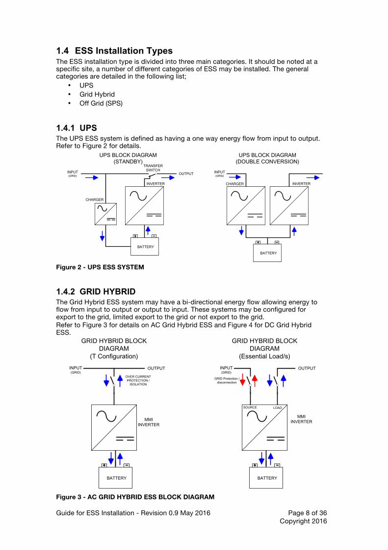
1.4.1 UPS The UPS ESS system is defined as having a one way energy flow from input to output. Refer to Figure 2 for details.
UPS BLOCK DIAGRAM(STANDBY)
INVERTER
CHARGER
TRANSFER SWITCH
BATTERY
UPS BLOCK DIAGRAM(DOUBLE CONVERSION)
INVERTERCHARGER
BATTERY
INPUT(GRID)
OUTPUT INPUT(GRID)
Figure 2 - UPS ESS SYSTEM
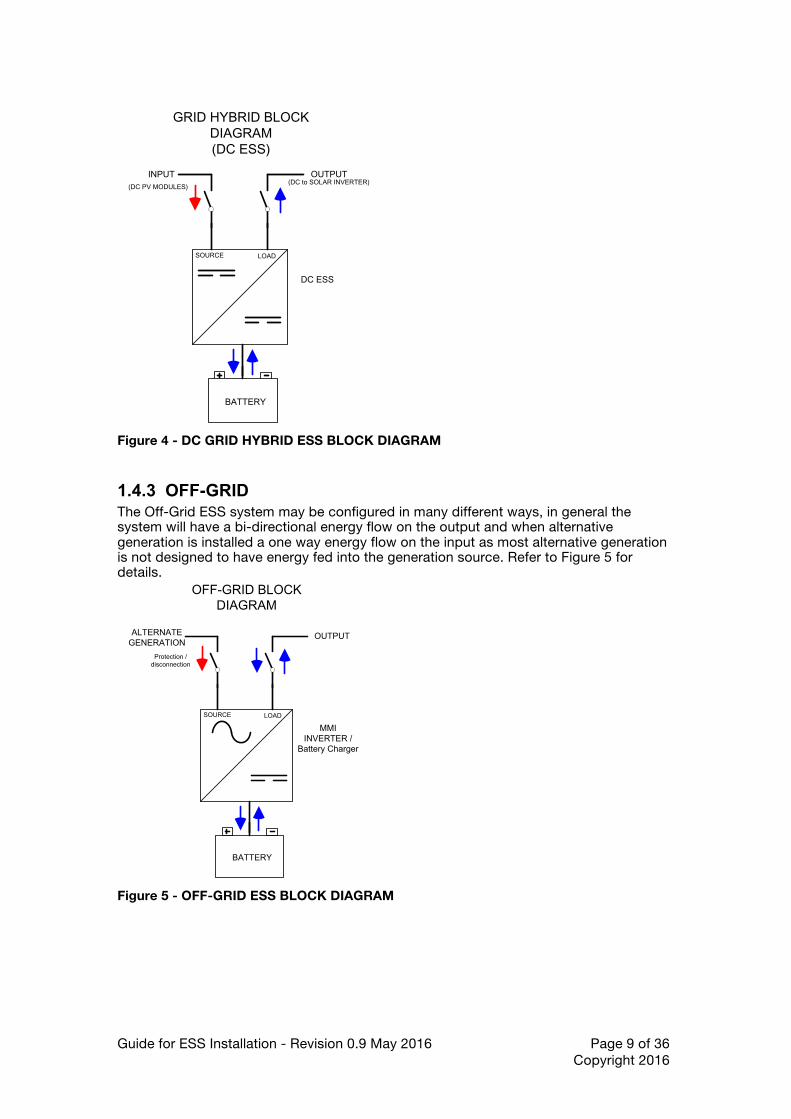
1.4.2 GRID HYBRID The Grid Hybrid ESS system may have a bi-directional energy flow allowing energy to flow from input to output or output to input. These systems may be configured for export to the grid, limited export to the grid or not export to the grid. Refer to Figure 3 for details on AC Grid Hybrid ESS and Figure 4 for DC Grid Hybrid ESS.
GRID HYBRID BLOCK DIAGRAM
(T Configuration)
MMI INVERTER
BATTERY
INPUT(GRID)
OUTPUT
OVER CURRENTPROTECTION /
ISOLATION
GRID HYBRID BLOCK DIAGRAM
(Essential Load/s)
MMI INVERTER
BATTERY
INPUT(GRID)
OUTPUT
GRID Protection / disconnection
SOURCE LOAD
Figure 3 - AC GRID HYBRID ESS BLOCK DIAGRAM
Guide for ESS Installation - Revision 0.9 May 2016 Page 9 of 36 Copyright 2016
GRID HYBRID BLOCK
DIAGRAM(DC ESS)
DC ESS
BATTERY
INPUT OUTPUT(DC PV MODULES)
SOURCE LOAD
(DC to SOLAR INVERTER)
Figure 4 - DC GRID HYBRID ESS BLOCK DIAGRAM
1.4.3 OFF-GRID The Off-Grid ESS system may be configured in many different ways, in general the system will have a bi-directional energy flow on the output and when alternative generation is installed a one way energy flow on the input as most alternative generation is not designed to have energy fed into the generation source. Refer to Figure 5 for details.
OFF-GRID BLOCK DIAGRAM
MMI INVERTER /
Battery Charger
BATTERY
ALTERNATE GENERATION
OUTPUT
Protection / disconnection
SOURCE LOAD
Figure 5 - OFF-GRID ESS BLOCK DIAGRAM
Guide for ESS Installation - Revision 0.9 May 2016 Page 10 of 36 Copyright 2016
1.4.4 Other ESS Functions In addition to the general ESS types, an ESS system may be used for one or a combination of the following;
• Load Shifting • Tariff Optimisation • Load Support or Demand Reduction • Renewable Export Mitigation • Network Support
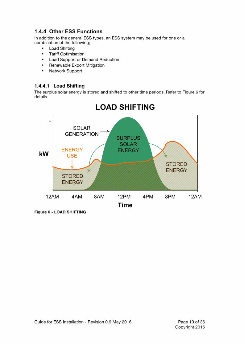
1.4.4.1 Load Shifting The surplus solar energy is stored and shifted to other time periods. Refer to Figure 6 for details.
12AM 4AM 8AM 12PM 4PM 8PM 12AM
ENERGYUSE
STORED ENERGY
STORED ENERGY
SURPLUSSOLAR
ENERGY
SOLAR GENERATION
LOAD SHIFTING
kW
Time Figure 6 - LOAD SHIFTING
Guide for ESS Installation - Revision 0.9 May 2016 Page 11 of 36 Copyright 2016
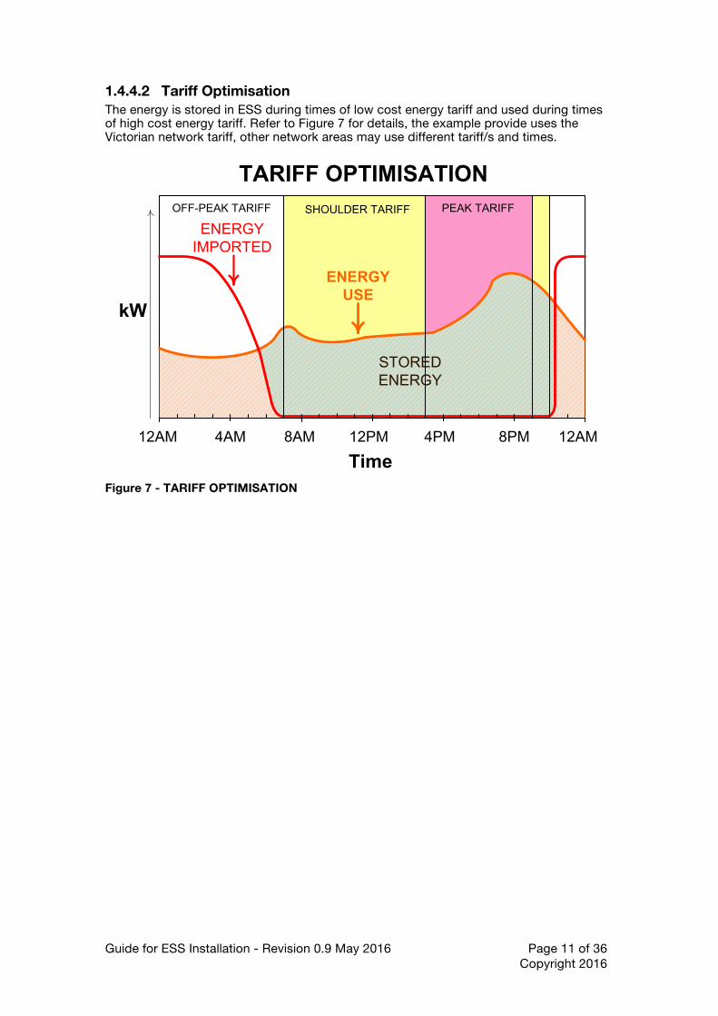
1.4.4.2 Tariff Optimisation The energy is stored in ESS during times of low cost energy tariff and used during times of high cost energy tariff. Refer to Figure 7 for details, the example provide uses the Victorian network tariff, other network areas may use different tariff/s and times.
12AM 4AM 8AM 12PM 4PM 8PM 12AM
ENERGYUSE
PEAK TARIFFOFF-PEAK TARIFF
STORED ENERGY
ENERGYIMPORTED
SHOULDER TARIFF
TARIFF OPTIMISATION
kW
Time Figure 7 - TARIFF OPTIMISATION

Guide for ESS Installation - Revision 0.9 May 2016 Page 12 of 36 Copyright 2016
1.4.4.3 Peak Lopping The peak energy used in many demand tariff supply arrangements can greatly affect the cost of energy for the entire billing / contract period. The ability of the ESS system to reduce the maximum demand on the network benefits both the network provider and the customer. Refer to Figure 8 for detailed example.
12AM 4AM 8AM 12PM 4PM 8PM 12AM
ENERGYUSE
PEAK TARIFFOFF-PEAK TARIFF OFFPEAK
TARIFF
STORED ENERGY
ENERGYIMPORTED
DEMAND TARIFF 2
DEMAND TARIFF 1
DEMAND TARIFF 3
PEAK LOPPING
kW
Time Figure 8 - PEAK LOPPING
1.4.4.4 Export Limiting The export of solar energy in some network operator controlled electricity distribution networks is either limited to a set maximum or not allowed at all for new solar customers. Export limiting may vary from "ZERO EXPORT" to minimal export. The ESS system can be used to store surplus solar energy for use at different time periods. Refer to Figure 9 for an example of an export limiting configuration.
12AM 4AM 8AM 12PM 4PM 8PM 12AM
ENERGYUSE
STORED ENERGY
STORED ENERGY
SURPLUSSOLAR ENERGY
SOLAR GENERATION
EXPORT LIMITING
kW
Time
EXPORTLIMITEXPORTED
ENERGY
Figure 9 - EXPORT LIMITING
Guide for ESS Installation - Revision 0.9 May 2016 Page 13 of 36 Copyright 2016
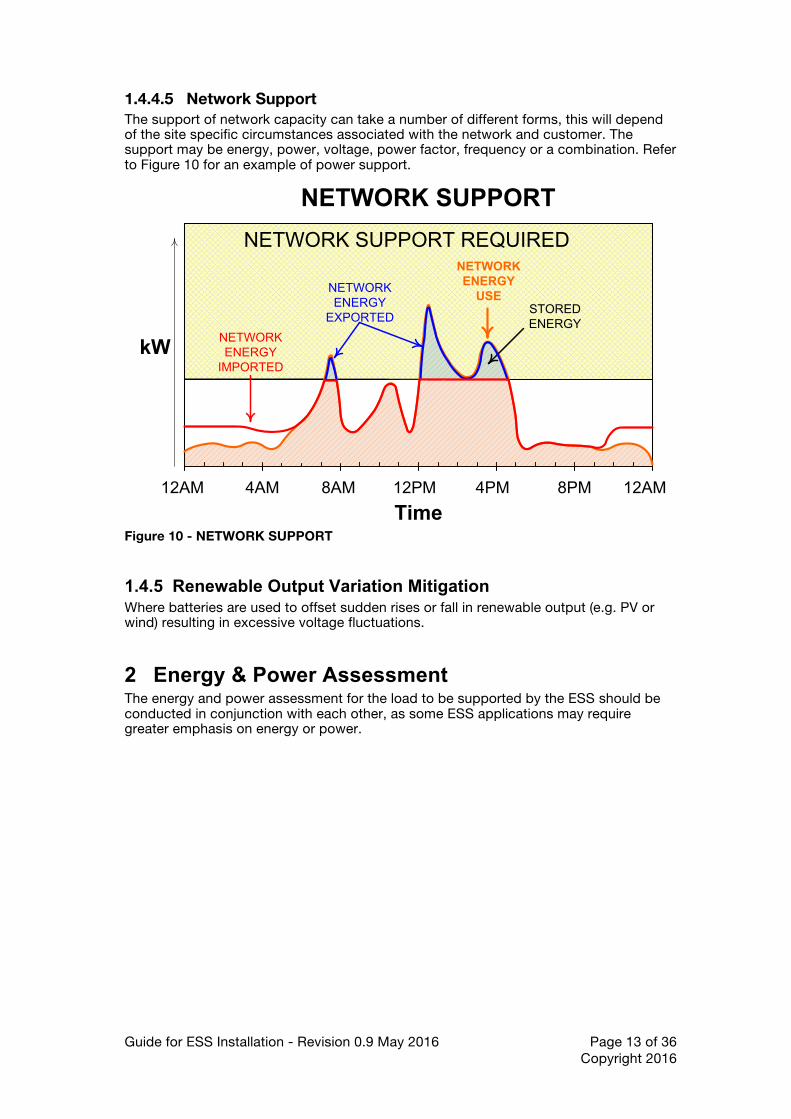
1.4.4.5 Network Support The support of network capacity can take a number of different forms, this will depend of the site specific circumstances associated with the network and customer. The support may be energy, power, voltage, power factor, frequency or a combination. Refer to Figure 10 for an example of power support.
12AM 4AM 8AM 12PM 4PM 8PM 12AM
NETWORKENERGY
USESTORED ENERGY
NETWORKENERGY
IMPORTED
NETWORK SUPPORT
kW
Time
NETWORK SUPPORT REQUIRED
NETWORK ENERGY
EXPORTED
Figure 10 - NETWORK SUPPORT
1.4.5 Renewable Output Variation Mitigation Where batteries are used to offset sudden rises or fall in renewable output (e.g. PV or wind) resulting in excessive voltage fluctuations.
2 Energy & Power Assessment The energy and power assessment for the load to be supported by the ESS should be conducted in conjunction with each other, as some ESS applications may require greater emphasis on energy or power.
Guide for ESS Installation - Revision 0.9 May 2016 Page 14 of 36 Copyright 2016
ENERGY ASSESSMENT
GRID HYBRID OFF GRID
DOMESTICCOMMERCIAL
& INDUSTRIAL
DOMESTICCOMMERCIAL
& INDUSTRIAL
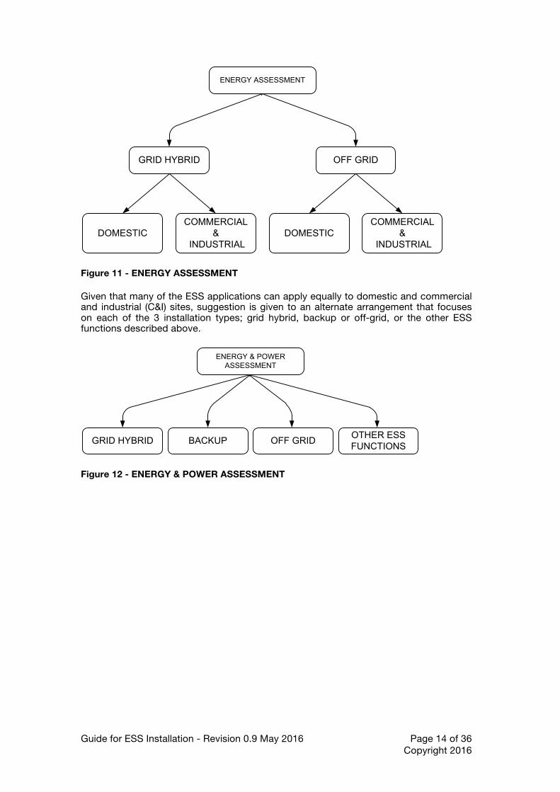
Figure 11 - ENERGY ASSESSMENT Given that many of the ESS applications can apply equally to domestic and commercial and industrial (C&I) sites, suggestion is given to an alternate arrangement that focuses on each of the 3 installation types; grid hybrid, backup or off-grid, or the other ESS functions described above.
ENERGY & POWER ASSESSMENT
GRID HYBRID OFF GRIDBACKUPOTHER ESS FUNCTIONS
Figure 12 - ENERGY & POWER ASSESSMENT

Guide for ESS Installation - Revision 0.9 May 2016 Page 15 of 36 Copyright 2016
3 Specifying — Energy Storage System Performance
Figure 13 - ESS SYSTEMS NOT EQUAL The specifying of performance parameters for an energy storage system shall be done using the following common minimum set of parameters. The common parameters allow for comparisons between system vendors quotes. The common parameters include; The Energy storage system shall be capable of at least the following;.
• Usable Energy (kWh) • Maximum Power output (kW) over what pf range (if AC output) • If AC output, operating pf range (leading to lagging) • Battery System - life time to be minimum of 8 years • ESS Maximum Surge Load (kVA) • ESS Maximum Power output • ESS output Power, time period of 1s, 30s, 1min, 30min and continuous • Maximum Recharge Power available from source or Maximum or Minimum
Recharge power allowed / required by storage device. • Battery Total Energy Throughput (MWh) • Standby SOC for storage device • Response Time in ms. • Storage Device self-discharge rate (usually %/month) • Energy Storage Device maximum prospective fault current and protective device
capability • Energy Storage Device operating DC Voltage range (if applicable) • Energy Storage Device maximum heat dissipation during operation • Backup up Power - Yes /No • Days of Autonomy - how long will the system support the load without
renewable energy input. • Warranty on equipment • Warranty on battery (including temperature ranges) • Operating temperature range • For AC Converters, fault clearance capability and protection devices included • Standards compliance eg AS3000, AS5033, AS4777, AS5603

Guide for ESS Installation - Revision 0.9 May 2016 Page 16 of 36 Copyright 2016
4 System Configuration The ESS system configuration is defined by a number of factors;
• Customers' Requirements • Manufactures Documentation and Intended use • Australian Standards & Utility Requirements
Examples of possible configurations for each system type are provided in this section. It should be noted the ESS system installation and intended use follows manufactures documentation.
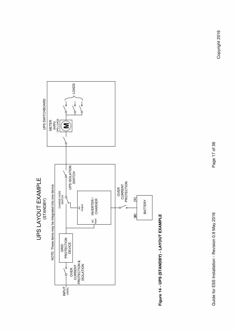
4.1 UPS UPS can be generally split into two categories;
• Standby • Online (with optional renewable generation)
The following diagrams show some of the possible methods that UPS system may be integrated into existing electrical systems.
Gui
de
for
ES
S In
stal
latio
n -
Rev
isio
n 0.
9 M
ay 2
016
Pag
e 17
of
36
Co
pyr
ight
201
6
UP
S L
AY
OU
T E
XA
MP
LE(S
TA
ND
BY
)
INV
ER
TE
R /
CH
AR
GE
R
CH
AN
GE
OV
ER
S
WIT
CH
BA
TT
ER
Y
INP
UT
(GR
ID)
UP
S IS
OLA
TIO
N
SW
ITC
HLO
AD
S
OV
ER
C
UR
RE
NT
P
RO
TE
CT
ION
GR
ID
PR
OT
EC
TIO
N
DE
VIC
EO
VE
R
CU
RR
EN
T
PR
OT
EC
TIO
N &
IS
OLA
TIO
N
UP
S S
WIT
CH
BO
AR
D
NO
TE
: The
se it
ems
may
be
inte
grat
ed in
to o
ne d
evic
eM
ET
ER
(kW
h)U
PS
LO
AD
S
M
AC
In
put
AC
O
utpu
t
Fig
ure
14
- U
PS
(ST
AN
DB
Y) -
LA
YO
UT
EX
AM
PL
E
Gui
de
for
ES
S In
stal
latio
n -
Rev
isio
n 0.
9 M
ay 2
016
Pag
e 18
of
36
Co
pyr
ight
201
6
UP
S (
ES
S)
LA
YO
UT
EX
AM
PLE
(with
OP
TIO
NA
L R
EN
EW
AB
LE G
EN
ER
AT
ION
)
INV
ER
TE
R /
CH
AR
GE
R
BA
TT
ER
Y
INP
UT
(GR
ID)
UP
S IS
OLA
TIO
N
SW
ITC
H
OV
ER
C
UR
RE
NT
P
RO
TE
CT
ION
GR
ID
PR
OT
EC
TIO
N
DE
VIC
EO
VE
R
CU
RR
EN
T
PR
OT
EC
TIO
N &
IS
OLA
TIO
N
NO
TE
: The
se it
ems
may
be
inte
grat
ed in
to o
ne d
evic
e
OP
TIO
NA
L D
C
CO
UP
LED
R
EN
EW
AB
LEG
EN
ER
AT
ION
(PV
, WIN
D, H
YD
RO
) N
OT
E 3
LOA
DS
(not
bac
ked
up b
y U
PS
)
ME
TE
R(k
Wh)
M
MA
INS
WIT
CH
[GR
ID]
ME
TE
RIS
OLA
TO
R
NO
RM
AL
SU
PP
LY S
WIT
CH
BO
AR
D
OP
TIO
NA
L U
NC
ON
TR
OLL
ED
AC
CO
UP
LED
R
EN
EW
AB
LEG
EN
ER
AT
ION
(PV
, WIN
D, H
YD
RO
)
MA
INS
WIT
CH
[UP
S IN
VE
RT
ER
S
UP
PLY
]
[UP
S
INV
ER
TE
R]
LOA
DS
(bac
ked
up
by U
PS
)
UP
S S
WIT
CH
BO
AR
D OP
TIO
NA
L A
C
CO
UP
LED
R
EN
EW
AB
LEG
EN
ER
AT
ION
(PV
, WIN
D, H
YD
RO
)N
OT
E 1
ME
TE
R(k
Wh)
UP
S L
OA
DS
M
NO
TE
3: D
C D
IRE
CT
BA
TT
ER
Y C
HA
RG
ING
from
O
PT
ION
AL
RE
NE
WA
BLE
GE
NE
RA
TIO
N m
ay o
nly
be
avai
labl
e on
cer
tain
bra
nds
/ mod
els
of E
SS
INV
ER
TE
R
and
batte
ry ty
pes.
NO
TE
1: T
he O
PT
ION
AL
DC
DIR
EC
T C
ON
NE
CT
ED
R
EN
EW
AB
LE G
EN
ER
AT
ION
may
onl
y be
ava
ilabl
e on
ce
rtai
n br
ands
/ m
odel
s of
ES
S IN
VE
RT
ER
.
OP
TIO
NA
L D
C
RE
NE
WA
BLE
GE
NE
RA
TIO
N(P
V, W
IND
, HY
DR
O)
NO
TE
2
NO
TE
2: T
he O
PT
ION
AL
DC
DIR
EC
T
CO
NN
EC
TE
D R
EN
EW
AB
LE G
EN
ER
AT
ION
m
ay o
nly
be a
vaila
ble
on c
erta
in b
rand
s /
mod
els
of E
SS
INV
ER
TE
R.
AC
In
put
AC
O
utpu
t
Fig
ure
15
- U
PS
(ES
S),
WIT
H R
EN
EW
AB
LE
- L
AY
OU
T E
XA
MP
LE

Gui
de
for
ES
S In
stal
latio
n -
Rev
isio
n 0.
9 M
ay 2
016
Pag
e 19
of
36
Co
pyr
ight
201
6
4.2
ES
S T
Co
nfi
gu
rati
on
T
he E
SS
sys
tem
pro
vid
es s
upp
ort
fo
r th
e lo
ad, i
f th
e m
ains
fai
l the
ES
S s
huts
do
wn.
ES
S s
yste
ms
sup
po
rt a
bi-
dire
ctio
nal e
nerg
y flo
w, s
our
ce /
load
to
bat
tery
and
bat
tery
to
so
urce
/ lo
ad. O
ptio
nal r
enew
able
gen
erat
ion
may
be
add
ed d
epen
dan
t o
n m
anuf
actu
res
equi
pm
ent
and
cus
tom
er
req
uire
men
ts.
ES
S T
CO
NF
IGU
RA
TIO
N L
AY
OU
T E
XA
MP
LE(w
ith O
PT
ION
AL
RE
NE
WA
BLE
GE
NE
RA
TIO
N)
INV
ER
TE
R /
CH
AR
GE
R
BA
TT
ER
Y
OV
ER
C
UR
RE
NT
P
RO
TE
CT
ION
GR
ID
PR
OT
EC
TIO
N
DE
VIC
EO
VE
R
CU
RR
EN
T
PR
OT
EC
TIO
N &
IS
OLA
TIO
N
NO
TE
: The
se it
ems
may
be
inte
grat
ed in
to o
ne d
evic
e
OP
TIO
NA
L D
C
RE
NE
WA
BLE
GE
NE
RA
TIO
N(P
V, W
IND
, HY
DR
O)
NO
TE
1
OP
TIO
NA
L D
C
CO
UP
LED
R
EN
EW
AB
LEG
EN
ER
AT
ION
(PV
, WIN
D, H
YD
RO
)N
OT
E 2
LOA
DS
(not
bac
ked
up b
y U
PS
)
ME
TE
R(k
Wh)
M
MA
INS
WIT
CH
[GR
ID]
ME
TE
RIS
OLA
TO
R
NO
RM
AL
SU
PP
LY S
WIT
CH
BO
AR
D
OP
TIO
NA
L U
NC
ON
TR
OLL
ED
AC
CO
UP
LED
R
EN
EW
AB
LEG
EN
ER
AT
ION
(PV
, WIN
D, H
YD
RO
)
MA
INS
WIT
CH
[ES
S IN
VE
RT
ER
S
UP
PLY
]
ME
TE
R(k
Wh)
ES
S L
OA
DS
M
NO
TE
2: D
C D
IRE
CT
BA
TT
ER
Y C
HA
RG
ING
from
O
PT
ION
AL
RE
NE
WA
BLE
GE
NE
RA
TIO
N m
ay o
nly
be
avai
labl
e on
cer
tain
bra
nds
/ mod
els
of E
SS
INV
ER
TE
R
and
batte
ry ty
pes.
NO
TE
1: T
he O
PT
ION
AL
DC
DIR
EC
T C
ON
NE
CT
ED
R
EN
EW
AB
LE G
EN
ER
AT
ION
may
onl
y be
ava
ilabl
e on
ce
rtai
n br
ands
/ m
odel
s of
ES
S IN
VE
RT
ER
.
F
igu
re 1
6 -
ES
S T
CO
NF
IGU
RA
TIO
N -
LA
YO
UT
EX
AM
PL
E
Gui
de
for
ES
S In
stal
latio
n -
Rev
isio
n 0.
9 M
ay 2
016
Pag
e 20
of
36
Co
pyr
ight
201
6
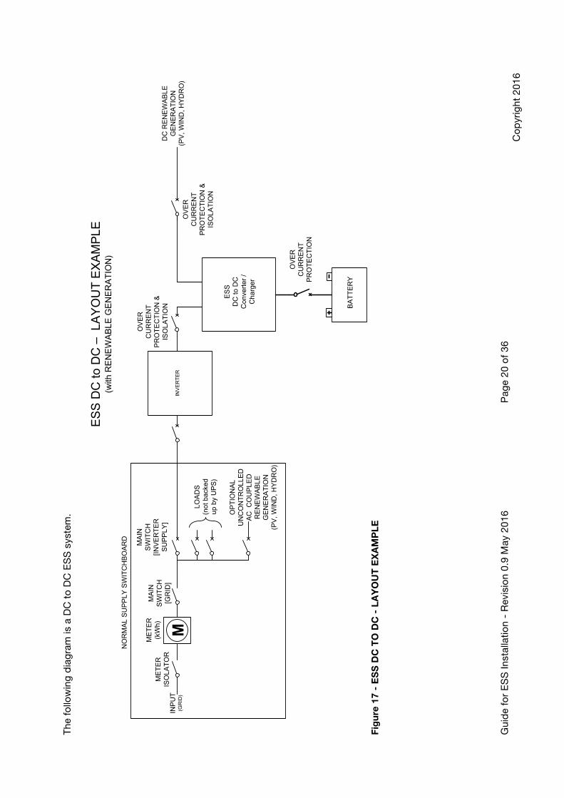
The
fo
llow
ing
dia
gra
m is
a D
C t
o D
C E
SS
sys
tem
.
ES
S D
C to
DC
– L
AY
OU
T E
XA
MP
LE(w
ith R
EN
EW
AB
LE G
EN
ER
AT
ION
)
ES
SD
C to
DC
C
onve
rter
/ C
harg
er
BA
TT
ER
Y
INP
UT
(GR
ID)
OV
ER
C
UR
RE
NT
P
RO
TE
CT
ION
INV
ER
TE
R
OV
ER
C
UR
RE
NT
P
RO
TE
CT
ION
&
ISO
LAT
ION
LOA
DS
(not
bac
ked
up b
y U
PS
)
ME
TE
R(k
Wh)
M
MA
INS
WIT
CH
[GR
ID]
ME
TE
RIS
OLA
TO
R
NO
RM
AL
SU
PP
LY S
WIT
CH
BO
AR
D
OP
TIO
NA
L U
NC
ON
TR
OLL
ED
AC
CO
UP
LED
R
EN
EW
AB
LEG
EN
ER
AT
ION
(PV
, WIN
D, H
YD
RO
)
MA
INS
WIT
CH
[INV
ER
TE
R
SU
PP
LY]
DC
RE
NE
WA
BLE
GE
NE
RA
TIO
N(P
V, W
IND
, HY
DR
O)
OV
ER
C
UR
RE
NT
P
RO
TE
CT
ION
&
ISO
LAT
ION
F
igu
re 1
7 -
ES
S D
C T
O D
C -
LA
YO
UT
EX
AM
PL
E
Gui
de
for
ES
S In
stal
latio
n -
Rev
isio
n 0.
9 M
ay 2
016
Pag
e 21
of
36
Co
pyr
ight
201
6
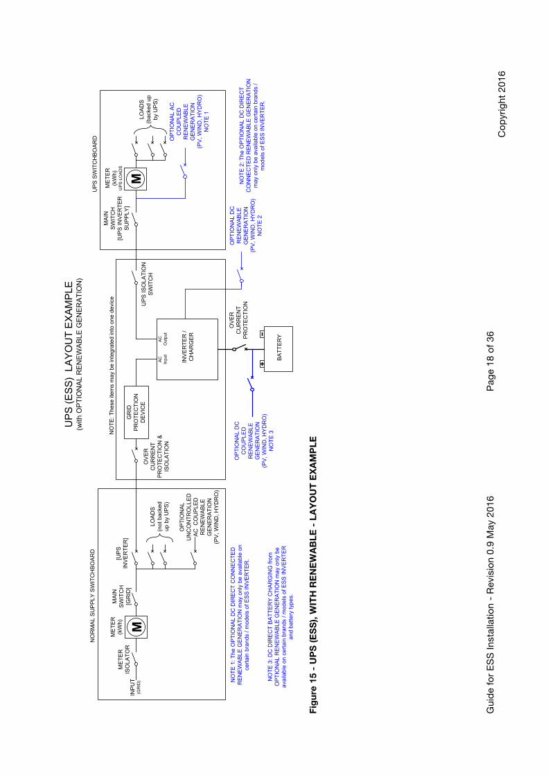
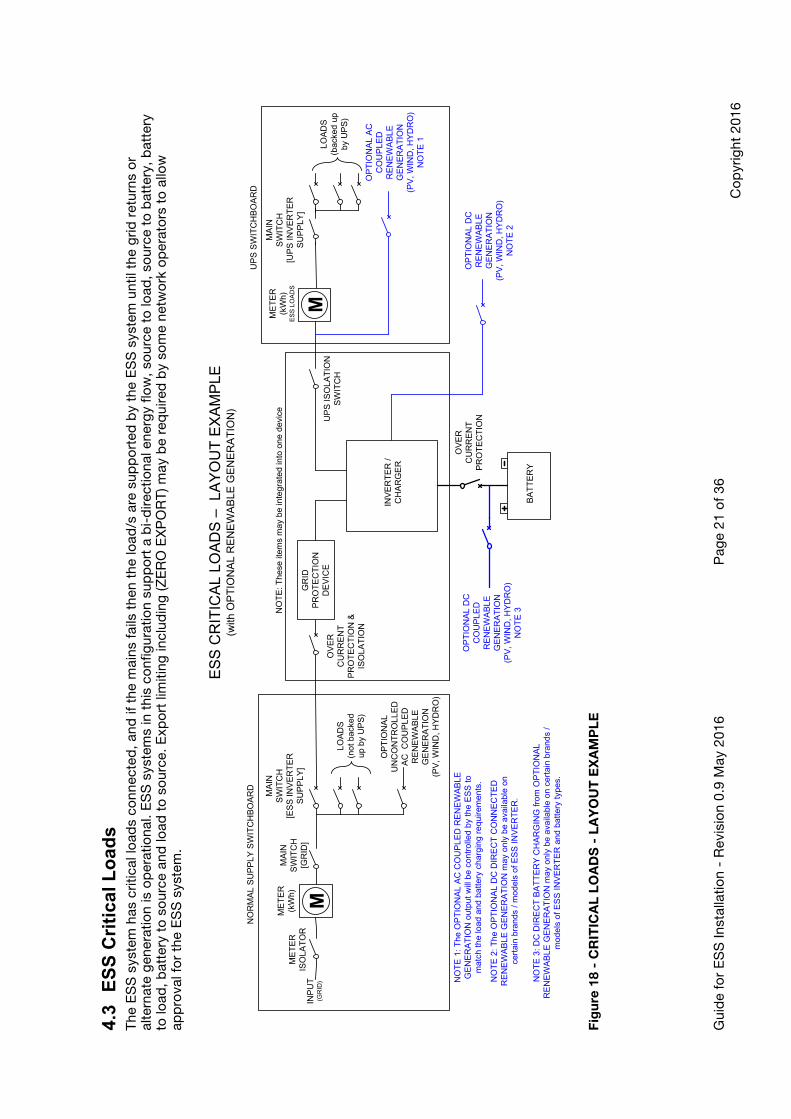
4.3
ES
S C
riti
cal L
oad
s T
he E
SS
sys
tem
has
crit
ical
load
s co
nnec
ted
, and
if t
he m
ains
fai
ls t
hen
the
load
/s a
re s
upp
ort
ed b
y th
e E
SS
sys
tem
unt
il th
e g
rid r
etur
ns o
r al
tern
ate
gen
erat
ion
is o
per
atio
nal.
ES
S s
yste
ms
in t
his
conf
igur
atio
n su
pp
ort
a b
i-d
irect
iona
l ene
rgy
flow
, so
urce
to
load
, so
urce
to
bat
tery
, bat
tery
to
load
, bat
tery
to
so
urce
and
load
to
so
urce
. Exp
ort
lim
iting
incl
udin
g (Z
ER
O E
XP
OR
T) m
ay b
e re
qui
red
by
som
e ne
two
rk o
per
ato
rs t
o a
llow
ap
pro
val f
or
the
ES
S s
yste
m.
ES
S C
RIT
ICA
L LO
AD
S –
LA
YO
UT
EX
AM
PLE
(with
OP
TIO
NA
L R
EN
EW
AB
LE G
EN
ER
AT
ION
)
INV
ER
TE
R /
CH
AR
GE
R
BA
TT
ER
Y
INP
UT
(GR
ID)
UP
S IS
OLA
TIO
N
SW
ITC
H
LOA
DS
(bac
ked
up
by U
PS
)
OV
ER
C
UR
RE
NT
P
RO
TE
CT
ION
GR
ID
PR
OT
EC
TIO
N
DE
VIC
EO
VE
R
CU
RR
EN
T
PR
OT
EC
TIO
N &
IS
OLA
TIO
N
UP
S S
WIT
CH
BO
AR
D
NO
TE
: The
se it
ems
may
be
inte
grat
ed in
to o
ne d
evic
e
OP
TIO
NA
L A
C
CO
UP
LED
R
EN
EW
AB
LEG
EN
ER
AT
ION
(PV
, WIN
D, H
YD
RO
)N
OT
E 1
OP
TIO
NA
L D
C
CO
UP
LED
R
EN
EW
AB
LEG
EN
ER
AT
ION
(PV
, WIN
D, H
YD
RO
)N
OT
E 3
LOA
DS
(not
bac
ked
up b
y U
PS
)
ME
TE
R(k
Wh)
M
MA
INS
WIT
CH
[GR
ID]
ME
TE
RIS
OLA
TO
R
NO
RM
AL
SU
PP
LY S
WIT
CH
BO
AR
D
OP
TIO
NA
L U
NC
ON
TR
OLL
ED
AC
CO
UP
LED
R
EN
EW
AB
LEG
EN
ER
AT
ION
(PV
, WIN
D, H
YD
RO
)
MA
INS
WIT
CH
[ES
S IN
VE
RT
ER
S
UP
PLY
]
MA
INS
WIT
CH
[UP
S IN
VE
RT
ER
S
UP
PLY
]
ME
TE
R(k
Wh)
ES
S L
OA
DS
M
OP
TIO
NA
L D
C
RE
NE
WA
BLE
GE
NE
RA
TIO
N(P
V, W
IND
, HY
DR
O)
NO
TE
2
NO
TE
1: T
he O
PT
ION
AL
AC
CO
UP
LED
RE
NE
WA
BLE
G
EN
ER
AT
ION
out
put w
ill b
e co
ntro
lled
by th
e E
SS
to
mat
ch th
e lo
ad a
nd b
atte
ry c
harg
ing
requ
irem
ents
.
NO
TE
2: T
he O
PT
ION
AL
DC
DIR
EC
T C
ON
NE
CT
ED
R
EN
EW
AB
LE G
EN
ER
AT
ION
may
onl
y be
ava
ilabl
e on
ce
rtai
n br
ands
/ m
odel
s of
ES
S IN
VE
RT
ER
.
NO
TE
3: D
C D
IRE
CT
BA
TT
ER
Y C
HA
RG
ING
from
OP
TIO
NA
L R
EN
EW
AB
LE G
EN
ER
AT
ION
may
onl
y be
ava
ilabl
e on
cer
tain
bra
nds
/ m
odel
s of
ES
S IN
VE
RT
ER
and
bat
tery
type
s.
Fig
ure
18
- C
RIT
ICA
L L
OA
DS
- L
AY
OU
T E
XA
MP
LE

Gui
de
for
ES
S In
stal
latio
n -
Rev
isio
n 0.
9 M
ay 2
016
Pag
e 22
of
36
Co
pyr
ight
201
6
4.4
ES
S O
ff G
rid
(S
tan
d A
lon
e P
ow
er S
yste
m)
The
ES
S s
yste
m d
oes
no
t ha
ve a
grid
co
nnec
tion.
Thu
s al
l the
ene
rgy
for
the
syst
em w
ill b
e su
pp
lied
fro
m r
enew
able
and
op
tiona
l alte
rnat
ive
gen
erat
ion.
Rec
om
men
dat
ions
fo
r sy
stem
des
ign
and
inst
alla
tion
are
out
lined
in A
S45
09. A
n ex
amp
le s
yste
m la
yout
is p
rovi
ded
in t
he f
ollo
win
g
dia
gra
m.
ES
S O
FF
-GR
ID –
LA
YO
UT
EX
AM
PLE
(with
OP
TIO
NA
L R
EN
EW
AB
LE G
EN
ER
AT
ION
)
INV
ER
TE
R /
CH
AR
GE
R
BA
TT
ER
Y
UP
S IS
OLA
TIO
N
SW
ITC
H
OV
ER
C
UR
RE
NT
P
RO
TE
CT
ION
SO
UR
CE
P
RO
TE
CT
ION
D
EV
ICE
OV
ER
C
UR
RE
NT
P
RO
TE
CT
ION
&
ISO
LAT
ION
NO
TE
: The
se it
ems
may
be
inte
grat
ed in
to o
ne d
evic
e
NO
TE
1: T
he O
PT
ION
AL
AC
CO
UP
LED
RE
NE
WA
BLE
G
EN
ER
AT
ION
out
put w
ill b
e co
ntro
lled
by th
e E
SS
to
mat
ch th
e lo
ad a
nd b
atte
ry c
harg
ing
requ
irem
ents
.O
PT
ION
AL
DC
C
OU
PLE
D
RE
NE
WA
BLE
GE
NE
RA
TIO
N(P
V, W
IND
, HY
DR
O)
NO
TE
3
ME
TE
R(k
Wh)
(GE
N)
M
SU
PP
LY C
HA
NG
E O
VE
R
SW
ITC
H
ES
S
OF
F
GE
NB
AC
KU
P
GE
NE
RA
TIO
NO
VE
R
CU
RR
EN
T
PR
OT
EC
TIO
N &
IS
OLA
TIO
NLO
AD
S
UP
S S
WIT
CH
BO
AR
D
OP
TIO
NA
L A
C
CO
UP
LED
R
EN
EW
AB
LEG
EN
ER
AT
ION
(PV
, WIN
D, H
YD
RO
)N
OT
E 1
MA
INS
WIT
CH
[UP
S IN
VE
RT
ER
S
UP
PLY
]
ME
TE
R(k
Wh)
TO
TA
L LO
AD
S
M
OF
F-G
RID
SW
ITC
HB
OA
RD
BA
CK
UP
GE
NE
RA
TO
R C
ON
TR
OL
NO
TE
2: T
he O
PT
ION
AL
DC
DIR
EC
T C
ON
NE
CT
ED
R
EN
EW
AB
LE G
EN
ER
AT
ION
may
onl
y be
ava
ilabl
e on
ce
rtai
n br
ands
/ m
odel
s of
ES
S IN
VE
RT
ER
.
OP
TIO
NA
L D
C
RE
NE
WA
BLE
GE
NE
RA
TIO
N(P
V, W
IND
, HY
DR
O)
NO
TE
2
NO
TE
3: D
C D
IRE
CT
BA
TT
ER
Y C
HA
RG
ING
from
O
PT
ION
AL
RE
NE
WA
BLE
GE
NE
RA
TIO
N m
ay o
nly
be
avai
labl
e on
cer
tain
bra
nds
/ mod
els
of E
SS
INV
ER
TE
R
and
batte
ry ty
pes.
OV
ER
C
UR
RE
NT
P
RO
TE
CT
ION
&
ISO
LAT
ION
NO
TE
4: T
he S
OU
RC
E p
rote
ctio
n de
vice
per
form
s th
e sa
me
func
tion
as th
e G
RID
Pro
tect
ion
Dev
ice
and
prev
ents
exp
ort o
f ene
rgy
to th
e S
OU
RC
E, o
nly
requ
ired
whe
n th
e S
OU
RC
E c
an’t
acce
pt r
ever
se e
nerg
y.
NO
TE
4
F
igu
re -
ES
S O
FF
-GR
ID -
LA
YO
UT
EX
AM
PL
E
Guide for ESS Installation - Revision 0.9 May 2016 Page 23 of 36 Copyright 2016
5 Selection of Battery Technology
5.1 General The ESS battery technology should be chosen to suit the application. Energy usage patterns, charge/discharge rates, and environmental characteristic are factors that need to be considered. ESS system safety shall be considered paramount in all phases of the system life cycle. The Safety Data Sheet (SDS) can provide valuable information with regards to the ESS potential hazards.
Safety Data Sheet(SDS)
v
5.2 Safety Data Sheet (SDS) The SDS shall be prepared in accordance with Safe Work Australia's "Code of Practice for Preparation of Safety Data Sheet for Hazardous Chemicals". The duty of manufacture and importer of a hazardous chemical / material. NOTES: Refer to Safe Work Australia's web site for more details, http://www.safeworkaustralia.gov.au/sites/swa/about/publications/pages/safety-data-sheets-hazardous-chemicals-cop

Guide for ESS Installation - Revision 0.9 May 2016 Page 24 of 36 Copyright 2016
5.2.1 SDS - Key Information Areas The SDS is used to provide information on hazards that may be a result of battery failure or normal operation. The key areas are detailed in Table 1.
Table 1 - SDS KEY INFORMATION AREAS
SDS Section Key Information Section 1 - Identification: Product identifier and chemical identity
Contact information for the importer / manufacture of battery technology
Section 2 – Hazard(s) identification Important information required for handling, transport and maintenance activities, this information would be an input to the Safe Method Work Statement
Section 3 - Composition and information on ingredients
The composition of the battery and in particular the electrolyte, the information from this is also critical as an input to assist with determining the battery category
Section 4 - First-aid measures Required information to provide first aid in the event of an incident
Section 5 - Fire-fighting measures The fire fighting measures provide information to the hazards created by the ESS during a fire. As fire is not part of normal operation of the ESS, this information is critical as an input to assist with determining the battery category.
Section 6 - Accidental Release Measures The accidental release measures provide information on the appropriate ways to respond to the release of chemicals, in the form of spills, leaks or other accidental release. This is so that the adverse effects on people, property and the environment at or near the incident can be prevented or minimised.
Section 14 - Transport Information This section provides basic classification information for the transportation or shipment of a hazardous chemical by road, rail, sea or air as required by relevant transport legislation. UN Number, Proper shipping name or Technical Name and Transport Hazard class
In addition to the key areas, the SDS also contains valuable information required during the ESS life cycle. As such the other sections of the SDS are required and are no less important than sections detailed in Table 1. The UN number is used in conjunction with HB 76, Dangerous Goods - Initial Emergency Response Guide, by fire fighters to expedite emergency response in the event of an accident involving dangerous goods.
Guide for ESS Installation - Revision 0.9 May 2016 Page 25 of 36 Copyright 2016
6 Hazards associated with batteries The main types of hazards associated with battery systems are:
• Electric shock hazard • Stored energy hazard • Chemical hazard • Flammable emission hazard • Thermal runaway • Transportation • Kinetic energy hazard • Manual Handling
Some hazards associated with batteries are not well documented or generally understood, the next revision of this guide will expand on the hazards mentioned above along with detail information in the following areas;
• Electric Shock - new requirements detailed IEC 62109 Standard • DC Arc Flash - no details or standards currently cover this area • Toxic atmosphere - no detail on which chemistries may product this hazard
under what conditions • Thermal runaway - Chemistry dependant, some are highly unstable, greater
detail required to understand the conditions that affect each chemistry • Transportation - transportation of dangerous goods is not well understood in
the energy storage industry.
7 Battery Classification The safety classification of batteries can be determined by the information obtained from key areas of the batteries SDS, in addition to results from battery / ESS system testing. The battery should be classified as belonging to at least one category, depending on the type of battery, internal chemistry and possible failure modes, multiple categories may be applicable depend on failure modes. Battery categories are —
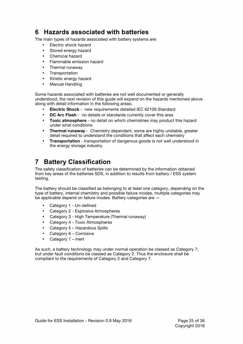
• Category 1 - Un-defined • Category 2 - Explosive Atmospheres • Category 3 - High Temperature (Thermal runaway) • Category 4 - Toxic Atmospheres • Category 5 – Hazardous Spills • Category 6 – Corrosive • Category 7 – Inert
As such, a battery technology may under normal operation be classed as Category 7, but under fault conditions be classed as Category 2. Thus the enclosure shall be compliant to the requirements of Category 2 and Category 7.
Guide for ESS Installation - Revision 0.9 May 2016 Page 26 of 36 Copyright 2016
Overall Enclosure Requirements
(Category / Categories)
Category 4(Toxic
Atmospheres)
Category 3(High
Temperature)
Category 2(Explosive
Atmospheres)
Category 1(Un-Defined)
Category 5(Hazardous
Spills)
Category 6(Corrosive)
Category 7(Inert)
Enslosure Requirements Flow Chart
Figure 19 - ENCLOSURE REQUIREMENTS FLOW CHART The requirements for each category flow up to the overall enclosure requirements.
7.1 Category 1 - Un-defined This category is used if insufficient information is provided in the SDS and battery performance testing, it is the catch all category, and enclosure capable of this type of battery shall be compliant to categories 2, 3, 4, 5, 6 and 7.
7.2 Category 2 - Explosive Atmospheres A category 2 battery will produce an explosive atmosphere during normal operation or under fault conditions.
7.3 Category 3 - High Temperature A category 3 battery will either operate at high temperatures or under fault conditions burn at very high temperatures. These types of batteries may also include chemistry that required specialised fire fighting equipment or materials to extinguish.
7.4 Category 4 - Toxic Atmospheres A category 4 battery will emit toxic fumes that would create a toxic atmosphere that is either fatal or causes long term medical condition even in very low consternations.
7.5 Category 5 - Hazardous Spills A category 5 battery will produce a hazardous spill if the battery electrolyte were to leak or be spilt. Toxic fumes or other issues may arise from the toxic spill that could cause long term health affects or be fatal. In general, the electrolyte will remain as a liquid and not vaporise completely upon leaking from the battery.
7.6 Category 6 - Corrosive A category 6 battery will produce a corrosive atmosphere if the electrolyte were to be leak or be spilt. Toxic fumes or other issues may arise from the corrosive atmosphere that could affect the battery storage enclosure or cause long term health effects or be fatal.
Guide for ESS Installation - Revision 0.9 May 2016 Page 27 of 36 Copyright 2016
7.7 Category 7 - Inert A category 7 battery system will not produce explosive atmosphere, emit toxic fumes, be subject to thermal runaway, produce toxic atmospheres, and produce hazardous spills or corrosive atmosphere. As such the battery still stores energy. There are other potential hazards that still require this category of battery to be protected.
8 Battery Accommodation Batteries should be protected by means of a suitable enclosure. This may take the form of a box, a room or a combination. It should be clean, dry, adequately ventilated, cooled, and provide and maintain protection against detrimental environmental conditions. The enclosure may be supplied by the battery manufacture as part of the overall ESS or be an additional component The following should be considered to determine the enclosure for the battery system;
• Cooling requirements - to maintain temperature within manufactures specifications
• Ventilation requirements - to maintain safety under normal operation and fault conditions
• Vermin - protection from. • Maintenance requirements
Some aspects associated with batteries are not well documented or generally understood with regards to the requirements for different chemistry, especially some of the more recent battery chemistries. The next revision of this guide will expand on the points mentioned above along with detail information in the following areas;;
• Ventilation - how should the enclosure be ventilate, where should the exhaust gas go
• Ventilation - of potentially toxic atmosphere for domestic installations • Cooling Requirements - how will the enclosure or ESS system maintain the
battery within a safe operation range in Australia's very hot climate. • Fire Protection - does an enclosure need a particular Fire Rating Level (FRL),
what conditions determine when an FRL is required. • Vermin - what level of vermin protection is required, with system having BMS
that maintain the system operation inside safe limits, do you need to prevent vermin from affecting the operation of the BMS and possible catastrophic failure of the ESS.
9 Battery Enclosure Requirements The battery enclosure shall provide suitable protection from the battery technology for the worst case, either during normal operation, during maintenance and under fault conditions. The battery enclosure may be provided by the battery manufacture or as an additional component. The battery enclosure is effectively the last line of defence, and provides the customer (user) and maintainer the PE (Protective Equipment) to remove the hazard. The Karlsruhe Institute of Technology (KIT), recommend for Li-Ion battery system be housed in a suitable enclosure.
Guide for ESS Installation - Revision 0.9 May 2016 Page 28 of 36 Copyright 2016
The specific requirements for each enclosure categories are not well documented for many of the newer chemistries. The next revision of this guide will provide detailed information in the following areas;
• FRL requirements • High temperature - requirements for time, thermal protection, what temperature • Toxic Atmospheres - levels of toxic atmosphere, controls to prevent the
enclosure being opened if a toxic atmosphere exists, alarms, ventilation. • Hazardous spill - how long is the spill need to be contained, are in built spill kits
/ controls required.
9.1 Enclosure Categories In general, a battery may be classified in one or more categories depending on the mode of operation (normal / fault condition). The enclosure for that battery may need to comply with the requirements of more than one category.
9.1.1 Category 1 - Un-defined The Battery Enclosure shall be designed to accommodate batteries of category 1 type.
9.1.2 Category 2 - Explosive Atmospheres The Battery Enclosure shall be designed to accommodate batteries of category 2 type.
9.1.3 Category 3 - High Temperature The Battery Enclosure shall be designed to accommodate batteries of category 3 type.
9.1.4 Category 4 - Toxic Atmospheres The Battery Enclosure shall be designed to accommodate batteries of category 4 type.
9.1.5 Category 5 - Hazardous Spills The Battery Enclosure shall be designed to accommodate batteries of category 5 type.
9.1.6 Category 6 - Corrosive The Battery Enclosure shall be designed to accommodate batteries of category 6 type.
9.1.7 Category 7 - Inert The Battery Enclosure shall be designed to accommodate batteries of category 7 type.
9.2 Enclosure - Egress and Access The Battery Enclosure shall have access to the batteries with sufficient space for safe installation, testing and maintenance. Suggest at least 900mm for batteries up to 150kg in weight, and 1200mm of space for battery cells / mono-blocks that weigh more than 150kg.
Guide for ESS Installation - Revision 0.9 May 2016 Page 29 of 36 Copyright 2016
10 Battery Room Requirements The Battery Room requirements are similar to the requirements of a battery enclosure, however as the battery room can be walked into, and then additional requirements may need to apply for some categories. The specific requirements for battery rooms are not well documented for many of the newer chemistries. The next revision of this guide will provide detailed information in the following areas;
• Toxic atmosphere - detection systems, which chemistries need this, and what levels are safe.
• Toxic / corrosive spill - requirements and other systems that need to be in place to mitigate disaster.
• High temperature batteries / faults - do rooms require fire suppression systems, and which type are suited to which chemistry
• Egress and Access - what requirements around larger batteries, some weights are up around 300kg per cell
• Remote shutdown • Remote monitoring - of system health and safety
11 Installation The current National Construction Code (NCC) divides buildings into classes. Class 1 & 10 are domestic dwellings where as class 2 through 9 are non-domestic dwellings. The NCC provides guidance for class 2 through 9 however does not cover class 1 & 10 in detail. The Australian Standard AS4086, AS3011 and AS4509 cover installation of battery systems. The standards are written around Lead Acid technology and don't account for the new chemistries and grid hybrid systems. The metrology detailed in the current standards can be applied, a chemistry non specific standard is required to cover a broad range of possibilities. The specific requirements for installation are not well documented for many of the newer chemistries. The next revision of this guide will provide detailed information in the following areas;
• Detailed requirements - domestic ESS installation locations, permissible locations
• Physical requirements - (size, weight), minimum area, access • Battery technology - additional requirements based on chemistry • Ventilation requirements - how venting is to be achieved, where is it
permissible and not permissible • Environmental considerations, e.g. temperature, exposure to direct sunlight,
weather, etc. • Intended use of the location • Access for emergency services • Remote shutdown capability - when is it required • Access control • Cabling - methods of protection, sizing • Electrical - installation, switchboards, control systems, layouts • Network - information required by network operators
Guide for ESS Installation - Revision 0.9 May 2016 Page 30 of 36 Copyright 2016
12 Labelling All electrical equipment shall be marked (labelled) according to the requirements for marking to local standards and regulations when applicable. The labelling for battery storage system is more extensive than a standard grid connected solar system. Also additional labels will be require for ESS system that are not currently covered by AS4777, AS5033 or AS4509. As such this section will provide guidance on how the ESS system should be labelled. The specific requirements for additional battery signage are not well documented for many of the newer chemistries. The next revision of this guide will provide detailed information in the following areas;
• Warning sign Battery - for use by emergency services • Labelling of switchboards - greater details and information on how UPS,
Normal Supply and Off-Grid switchboards should be labelled. • Labelling requirements - chemistry specific, what information needs to be
provided • Spark & Arc Flash Hazards - what signs and information is required. • Battery Rooms - requirements for additional information • Installer Guides - Quick Reference for labelling. • Label Quality - requirements on how long a label should last, UV, fire, heat
12.1 FIRE EMERGENCY SERVICES INFORMATION The introduction of different battery chemistries presents a significant risk to emergency service personal. As chemistry specific response methods are required. The Australian Standard HB76 Dangerous Goods - Initial Emergency Response Guide details how the emergency service should respond.
Guide for ESS Installation - Revision 0.9 May 2016 Page 31 of 36 Copyright 2016
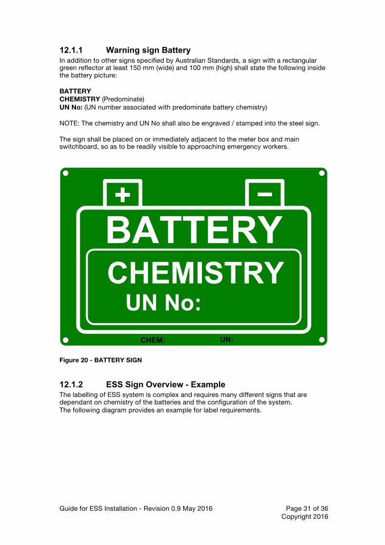
12.1.1 Warning sign Battery In addition to other signs specified by Australian Standards, a sign with a rectangular green reflector at least 150 mm (wide) and 100 mm (high) shall state the following inside the battery picture: BATTERY CHEMISTRY (Predominate) UN No: (UN number associated with predominate battery chemistry) NOTE: The chemistry and UN No shall also be engraved / stamped into the steel sign. The sign shall be placed on or immediately adjacent to the meter box and main switchboard, so as to be readily visible to approaching emergency workers.
BATTERYCHEMISTRY
UN No:
CHEM: UN:
Figure 20 - BATTERY SIGN
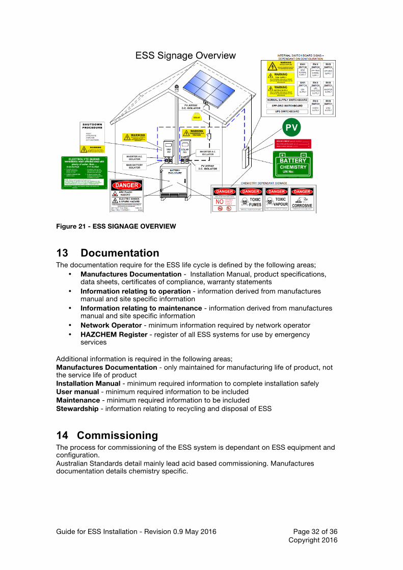
12.1.2 ESS Sign Overview - Example The labelling of ESS system is complex and requires many different signs that are dependant on chemistry of the batteries and the configuration of the system. The following diagram provides an example for label requirements.
Guide for ESS Installation - Revision 0.9 May 2016 Page 32 of 36 Copyright 2016
Figure 21 - ESS SIGNAGE OVERVIEW
13 Documentation The documentation require for the ESS life cycle is defined by the following areas;
• Manufactures Documentation - Installation Manual, product specifications, data sheets, certificates of compliance, warranty statements
• Information relating to operation - information derived from manufactures manual and site specific information
• Information relating to maintenance - information derived from manufactures manual and site specific information
• Network Operator - minimum information required by network operator • HAZCHEM Register - register of all ESS systems for use by emergency
services Additional information is required in the following areas; Manufactures Documentation - only maintained for manufacturing life of product, not the service life of product Installation Manual - minimum required information to complete installation safely User manual - minimum required information to be included Maintenance - minimum required information to be included Stewardship - information relating to recycling and disposal of ESS
14 Commissioning The process for commissioning of the ESS system is dependant on ESS equipment and configuration. Australian Standards detail mainly lead acid based commissioning. Manufactures documentation details chemistry specific.
Guide for ESS Installation - Revision 0.9 May 2016 Page 33 of 36 Copyright 2016
Additional detail covering the following areas will be provided in the next revision of this guide;
• Check List - covering chemistry non-specific checks • Check List - covering chemistry specific checks, this may include brand specific
checks • Audits - what level of auditing is required to ensure compliance and safety.
15 Maintenance The frequency of maintenance to be carried out on an ESS system is dependant of the type of technology, manufactures recommendations, customer site, network operator requirements and customer requirements. The current Australian Standards provide some guidance on the frequency of maintenance. Different network operators require different frequency of maintenance. Additional detail covering the following areas will be provided in the next revision of this guide;
• General Maintenance Requirements - non chemistry specific and chemistry specific
• Electrical equipment - manufactures, network operators and site specific requirements for particular types of ESS equipment.
• User Accessible Areas - maintenance is suitable for user, access & egress for user, requirements for hazard mitigation during user maintenance
• Maintainer Accessible Areas - access & egress for maintainer, requirements for hazard mitigation during maintainer maintenance activities, WHS requirements
• Training and accreditation for maintainer - manufacture specific and national accreditation
16 Stewardship At a point in time after the ESS system has been commissioned, the ESS system will reach the end of it's life. As a number of new chemistries currently don't have common recycling process in place it is difficult for the consumer to ensure the equipment is recycled correctly. Without a pre-defined process in place, hazardous materials may end up in land fill creating environmental issues. Product stewardship is critical to the ESS system life cycle, and planning for the disposal should be undertaken at the installation stage.

Guide for ESS Installation - Revision 0.9 May 2016 Page 34 of 36 Copyright 2016
Additional information is required in the following areas; • Chemistry specific stewardship guidelines • Lists of recycling centre/s - that will accept the various chemistry • Manufacture based recycling - fall back plan if manufacture / importer no
longer exists • Education and Training - training of existing recycling centres to understand
the various chemistries / equipment that may be presented to them and the associated hazards
17 Australian Standards The current Australian Standards don't cover many critical areas creating potential safety hazards for ESS installers, ESS owners / operators and the general public. The number of ESS systems are steadily increasing, the quality and safety of these systems ranges from barely adequate to systems that employ multiple levels of redundant safety systems. As a matter of urgency, a new Australian Standard is required to ensure that the barely adequate ESS systems are moved into an adequate safety zone. A non chemistry specific standard is required to address the impending safety issues associated with the increasing number of ESS systems being installed. The research conducted by CSIRO, KIT and DNVGL along with many other organisations indicates unless a new standard is developed and released soon the potential for damage to property and life will be much greater than the issues associated with installation of insulation in Australian houses. URGENT ACTION is required in the following areas;
• Development of ESS Best Practice Guide - interim standard for ESS sales, design and installation
• Development of ESS Australian Standards AS5139.1 - Sales, Design & Installation
• Development of ESS Battery Safety Testing - AS5139.2 - Chemistry specific safety tests for batteries, BMS, ESS systems
• Approved products list - whitelist of products approved for use in Australia and network operator areas

Guide for ESS Installation - Revision 0.9 May 2016 Page 35 of 36 Copyright 2016
This page has been left intentionally blank.
The Australian Battery Guide by
Copyright 2016