advanced battery storage systems testing at...
TRANSCRIPT
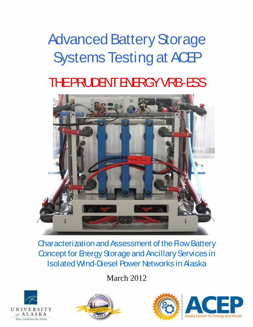
Advanced Battery Storage Systems Testing at ACEP
THE PRUDENT ENERGY VRB-ESS
Characterization and Assessment of the Flow Battery Concept for Energy Storage and Ancillary Services in
Isolated Wind-Diesel Power Networks in Alaska
March 2012

Cover photo of the 5 kw, 20 kWh Vanadium Redox Flow Battery System courtesy of Prudent Energy. Any comments or suggestions may be directed to the authors at the respective addresses below. Billy Muhando Asst Research Prof Alaska Center for Energy and Power (ACEP) University of Alaska Fairbanks [email protected] 1 907 474 7082 www.uaf.edu/acep Tom Johnson Research Engineer Alaska Center for Energy and Power (ACEP) University of Alaska Fairbanks [email protected] 1 907 474 5564 www.uaf.edu/acep Further information may be obtained by contacting: Gwen Holdmann Director Alaska Center for Energy and Power (ACEP) University of Alaska [email protected] 1 907 474 5402
Disclaimer
This report was prepared by the Alaska Center for Energy and Power (ACEP) as an account of work sponsored by an agency of the United States Government – the Denali Commission – and is disseminated in the interest of information exchange and general guidance only. Neither the United States Government nor any agency thereof, nor the state of Alaska, nor any of their employees, makes any warranty, express or implied, or assumes any legal liability or responsibility for the accuracy, completeness, or usefulness of any information, apparatus, product, or process disclosed, or represents that its use would not infringe privately owned rights. Reference herein to any specific commercial product, process, or service by trade name, trademark, manufacturer, or otherwise does not necessarily constitute or imply its endorsement, recommendation, or favoring by the United States Government, the state of Alaska, or any agency thereof.

Preface With the implementation of state and possibly federal renewable portfolio standards, there is a significant increase in the penetration of intermittent, non-dispatchable energy sources, as evidenced by the upsurge in the deployment of wind-diesel systems in the electricity generation infrastructure in various off-grid rural or village power applications in Alaska. The variability associated with these energy sources has a substantial impact on the respective power networks, and energy storage provides one approach for addressing some of the impacts. It is imperative to upgrade the current power systems to higher performance levels required to support continued economic growth and to improve productivity.
High penetration systems can be enabled significantly by developing managed, efficient, reliable, and economical energy storage technologies that eliminate the need for back-up utility baseload capacity to offset the intermittent and fluctuating nature of wind. Large-scale energy storage signifies there is ‘energy on demand’ that enhances the reliability of the power system, can defer or reduce transmission system investments, and can capture alternative energy generated off-hours for use during peak load periods. Optimally, the energy storage solution should be a low-maintenance, environmentally-friendly and modular construction to provide maximum benefit to the diverse set of stakeholders to address the issues at the electric grid now and in the future for purposes of planning and implementing investments needed to address impacts of alternative generation.
The Alaska center for Energy and Power (ACEP) has been involved in advanced battery research by testing and evaluating battery systems for integration with renewable energy projects on remote power grids in rural Alaska communities. The report documents the methodology, key assumptions, and results of a preliminary qualitative and quantitative analysis of a 5 kW, 20 kWh Prudent Energy flow battery system tested between September 2010 and December 2011. The primary goal of this report is to initiate stakeholder discussion regarding the deployment of flow battery energy storage in wind-diesel systems in Alaska and the investment needed to upgrade the current power systems to the higher performance levels required to support continued economic growth and to improve productivity.
TABLE OF CONTENTS
EXECUTIVE SUMMARY ............................................................. Error! Bookmark not defined.
ACKNOWLEDGMENTS ............................................................... Error! Bookmark not defined.
GLOSSARY ................................................................................. Error! Bookmark not defined.
INTRODUCTION ........................................................................................................................ 1
Background and Context .................................................. Error! Bookmark not defined. Fundamentals of Vanadium Redox Flow Battery Systems Error! Bookmark not defined. Previous Work .................................................................. Error! Bookmark not defined.
ANALYSIS ...................................................................... ERROR! BOOKMARK NOT DEFINED.
Lists .................................................................................. Error! Bookmark not defined. Figures ............................................................................. Error! Bookmark not defined. Tables .............................................................................. Error! Bookmark not defined. Display Equations ............................................................. Error! Bookmark not defined.
ANALYSIS ...................................................................... ERROR! BOOKMARK NOT DEFINED.
Characterization/Performance Testing.............................. Error! Bookmark not defined. Analysis of Results and Discussion .................................. Error! Bookmark not defined.
PERSPECTIVES ............................................................ ERROR! BOOKMARK NOT DEFINED.
VRB-ESS for Alaska? ....................................................... Error! Bookmark not defined. Cost Analysis .................................................................... Error! Bookmark not defined. R & D, Demonstration Projects ......................................... Error! Bookmark not defined. Future Work...................................................................... Error! Bookmark not defined.
APPENDIX ...................................................................... ERROR! BOOKMARK NOT DEFINED.
Specifications of the VRB-ESS ......................................... Error! Bookmark not defined. Additional Resources ........................................................ Error! Bookmark not defined.

LIST OF FIGURES
Figure 1. ...................................................................................... Error! Bookmark not defined.
LIST OF TABLES
Table 1. ....................................................................................... Error! Bookmark not defined.

Executive Summary Project Background The use of alternative and renewable energy sources on a large scale requires new technologies such as advanced energy storage systems. Multiple integration studies have suggested that the challenge of integrating renewables increases in a non-linear fashion as penetration levels exceed 20%. Alaska is already home to several systems pairing wind turbines with diesel power plants, and one of the challenges for these systems is the unpredictable wind system dynamics. Bulk storage is one of the major limitations in today’s “just in time” electricity delivery system and one of the great opportunities for Smart Grid development in the future. In perspective, and for Alaska in particular, storage—as both an end user and electric utility energy management resource —will become possible due to a confluence of high penetration wind-diesel systems deployment, dynamic pricing, and lower cost energy storage systems.
The genesis of this project was a proposal for the Alaska Center for Energy and Power (ACEP), partnering with the UAF Chukchi Campus, to assess small-scale advanced storage systems in support of the Kotzebue Electric Association (KEA) Premium Power Battery Project. Funding was provided through the Denali Commission Emerging Technologies Grant Fund for obtaining and testing the flow battery system. The funding for this project was intended as a subaward to KEA’s larger grant in recognition of the need to support ACEP’s research program in assessing other battery storage options appropriate for Alaskan markets. The research project involved characterization of a 5 kW, 20 kWh vanadium redox flow battery (VRB) system supplied by Prudent Energy Systems. The project has been conducted at the ACEP facilities in collaboration with the UAF Chukchi Campus, who purchased the battery for testing and will use data generated from this work as part of their sustainability curriculum. The project begun in September 2010 and the first phase that involved verifying manufacturer specifications was completed in December 2011.
The program goals are twofold: 1) to provide early access of performance and durability data for utilities that manage isolated grid systems to make informed decisions about future deployment of large-scale energy storage systems in Alaska, and 2) to improve the academic research infrastructure at the University of Alaska Fairbanks related to distributed energy technologies. The overall analysis is based on testing and evaluation of the VRB unit to characterize the performance and durability of the technology by considering the duty cycle, discharge rate, dynamic voltage control on a distribution line, round-trip efficiency, cold climate operation, and other functioning issues. Initial results have been encouraging – there is strong indication that vanadium redox flow battery systems are potentially suitable for distribution grid support applications.
The VRB System Prudent Energy’s VRB storage system is an advanced flow battery technology designed to store and supply large amounts of electricity on demand. The VRB contains two different electrolyte solutions of vanadium and sulphuric acid, each in a separate tank (positive and negatively charged, respectively). To provide power, the VRB electrolytes flow through a fuel cell stack on opposite sides of an ionic exchange membrane, where their opposite charges create a gradient that powers an external current.
Scalability: unlike conventional batteries, power output is independent from energy storage capacity—output depends on the size of the fuel cell stack, while the energy storage capacity depends on the size of the electrolyte tanks. This unique characteristic enables flow battery systems to sustain utility-scale storage and power at potentially competitive prices. Note, however, that the ratio of storage to power determines how long the batteries can run without recharging (power can flow undiminished as long as there is fresh electrolyte to circulate through the stack).
Pertinent Issues and Perspectives Wind energy is a critical component of ACEP’s larger energy storage program objectives, both because many of the issues addressed as part of the program are unique to Alaska, and because the existing need is greatest in the energy sector based on total installed and planned projects. Some crucial areas ACEP is focusing on include:
1. Economic considerations – an assessment of the overall cost, in relation to other storage media and to other manufacturers/suppliers will determine whether the flow battery is justified in larger communities in conjunction with a wind turbine to stabilize delivered power (the VRB unit is $$$/kWh).
2. Battery life and maintenance – reliability of the battery rely on the maintenance of the system, while the maintenance schedule intervals (cycles or service life hours) determine the offline duration. The design life of the battery is pegged at slightly over 10,000 cycles (and/or a service life of 100,000 hrs). Warranty issues and technical support need to be explored and established.
3. Cold climate and operational limits – with regard to suitability for Alaska, the electrolyte is fairly robust but is not to be exposed to extreme temperatures. Recommended electrolyte temperature range is 10 to 35 degC (during operation), while the allowable storage temperature range is -25 to 70 degC.
Alaska is an ideal test bed for emerging energy technology; given the momentum of wind-diesel systems developments, flow battery energy storage can prove economically viable. To address issues specifically related to operation of wind-diesel systems and showcase storage technologies that have the potential for spinning reserve and ancillary service provision, ACEP will integrate the VRB system with the wind turbine simulator test bed as part of the test protocols for the next phase of the research.
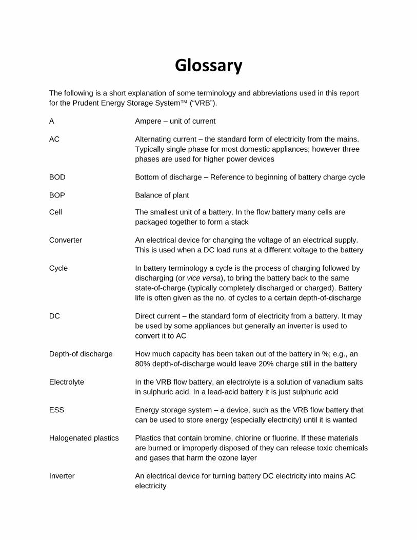
Glossary The following is a short explanation of some terminology and abbreviations used in this report for the Prudent Energy Storage System™ (“VRB”).
A Ampere – unit of current
AC Alternating current – the standard form of electricity from the mains. Typically single phase for most domestic appliances; however three phases are used for higher power devices
BOD Bottom of discharge – Reference to beginning of battery charge cycle
BOP Balance of plant
Cell The smallest unit of a battery. In the flow battery many cells are packaged together to form a stack
Converter An electrical device for changing the voltage of an electrical supply. This is used when a DC load runs at a different voltage to the battery
Cycle In battery terminology a cycle is the process of charging followed by discharging (or vice versa), to bring the battery back to the same state-of-charge (typically completely discharged or charged). Battery life is often given as the no. of cycles to a certain depth-of-discharge
DC Direct current – the standard form of electricity from a battery. It may be used by some appliances but generally an inverter is used to convert it to AC
Depth-of discharge How much capacity has been taken out of the battery in %; e.g., an 80% depth-of-discharge would leave 20% charge still in the battery
Electrolyte In the VRB flow battery, an electrolyte is a solution of vanadium salts in sulphuric acid. In a lead-acid battery it is just sulphuric acid
ESS Energy storage system – a device, such as the VRB flow battery that can be used to store energy (especially electricity) until it is wanted
Halogenated plastics Plastics that contain bromine, chlorine or fluorine. If these materials are burned or improperly disposed of they can release toxic chemicals and gases that harm the ozone layer
Inverter An electrical device for turning battery DC electricity into mains AC electricity
ii
kW Kilowatt (thousand watt) – unit of power. Mathematically it is equal to the current multiplied by the voltage
kWh Kilowatt-hour – unit of energy. Mathematically it is equal to the power multiplied by the usage time
Load Anything that takes electricity to work. In this description it is any appliance connected to the flow battery
Oxidation state A numerical measure of how far a substance has reacted. Vanadium in the VRB can have oxidation states +2 (little reacted), +3, +4 or +5 (fully reacted)
Redox Reduction-oxidation chemical reaction
Smart controller An essential device in the VRB that continuously monitors the state of the battery and power to the loads. It controls the speed of the pumps, number of stages in operation, responds to alarm signals and can communicate with the user
SOC State-of-charge – how much capacity (%) remains in the battery
Stack A group of cells through which the electrolytes flow. At both ends of the stack are electrical connectors, through which the battery may be charged and discharged
Stage In the VRB not all of the stacks must be active at the same time, especially when the power is low. The controller can decide to activate or deactivate groups of stacks together, known as a stage
String A group of batteries that are connected in series, i.e. positive to negative terminals
Thermal mass A measure of how difficult it is to raise the temperature of an object. The VRB has a higher thermal mass than an equivalent amount of lead-acid batteries
TOC Top of charge
V Volt – unit of voltage/ potential difference
Vanadium A common metal that is widely distributed in nature. It reacts to form brightly colored salts that are used in solution in the VRB
VRB Vanadium Redox Battery

RR XX-XX | Dec 2011
Introduction BACKGROUND AND CONTEXT
Proposal and Award
In August 2009, the University of Alaska applied for funding from the Denali Commission Emerging Technologies Grant Fund to test advanced battery systems. The 5 kW, 20 kWh vanadium redox battery was purchased from Prudent Energy Systems for laboratory testing at ACEP for both performance data collection and assessment of validity of the claims made by the supplier with regard to performance. The project was carried out for joint research and educational purposes – a cooperative partnership between the Chukchi Campus, University of Alaska Fairbanks, and the Alaska Center for Energy and Power (ACEP), University of Alaska-Fairbanks.
The battery unit was commissioned in September 2010, and ACEP has performed the requisite tests as outlined in the grant proposal. Collection of clean performance data to assess the validity of the claims made by the supplier is still ongoing at the ACEP facility, and the next step is to integrate the flow battery into a wind turbine simulator test bed as part of the program to assess energy storage options appropriate for Alaskan markets.
This report documents the testing and analysis of the project.
Project Objectives/ Scope of Work
The Chukchi Campus and ACEP entered into a cooperative arrangement such that the Chukchi campus would purchase a Prudent Energy 5 kW system, and have it shipped to the ACEP laboratory in Fairbanks for performance testing. The specific responsibilities for ACEP were set out as follows:
1. Test the unit for up to 6 months. The purpose would be to verify manufacturer performance claims in a controlled environment with managed charge/discharge cycles, and to determine if any significant maintenance issues exist.
2. ACEP would work with the Chukchi Campus to integrate the battery testing into the classroom by a) sending a researcher to Kotzebue to present a lecture(s) on energy storage; and b) show the battery in testing configuration and give a ‘tour’ of it via distance education technologies.

ACEP 11-03 | Dec 2011
ADVANCED ENERGY STORAGE RESEARCH 2 | P a g e
3. ACEP researchers would assist the Chukchi Campus in selecting an appropriate location in Arctic Northwest Alaska served by the Chukchi Campus, where the system would be integrated with an existing renewable energy project. This decision would be made in consultation with local utilities, particularly the Kotzebue Electric Association, and take into account both future educational opportunities for working with the battery as well as the ability to continue long-term performance monitoring in the field. The Chukchi Campus, as the owner of the battery system, would have the final decision making authority in this mater.
4. ACEP would work to prepare and ship the unit as appropriate. 5. ACEP would install remote monitoring and data collection equipment on the
system in the field (included in project budget). The goal was to have monitoring feeds installed at both Fairbanks and the Chukchi Campus via internet link.
Project Timeline
It was anticipated that the project would be undertaken over a period of 19 months, with the following specific milestones:
March 1st, 2010: Project start date March, 2010: Procurement for the 5 kW Prudent Energy System initiated July, 2010: Delivery of Prudent Battery in Fairbanks August, 2010: Installation of battery at ACEP facility September, 2011: Commissioning by Prudent Energy Systems personnel December, 2011: Project closeout; final Report.
Progress reports were completed quarterly throughout the project. Budget The project operated under a budget of $$$. Major project costs were divided as follows:
1. Each organization (ACEP and Chukchi Campus) supported its own representatives working on the project in terms of time and travel. The majority of this cost was borne by ACEP, at a cost to the organization of $75,001.
2. The Chukchi Campus covered all equipment costs, including the battery and remote monitoring and data logging equipment that allow performance data to be transmitted from the battery location.
In the event that the system would be relocated from the ACEP facility (for, e.g., field testing), Chukchi Campus is obligated to cover shipping of the unit.
ACEP 11-03 | Dec 2011
ADVANCED ENERGY STORAGE RESEARCH 3 | P a g e
Delivery
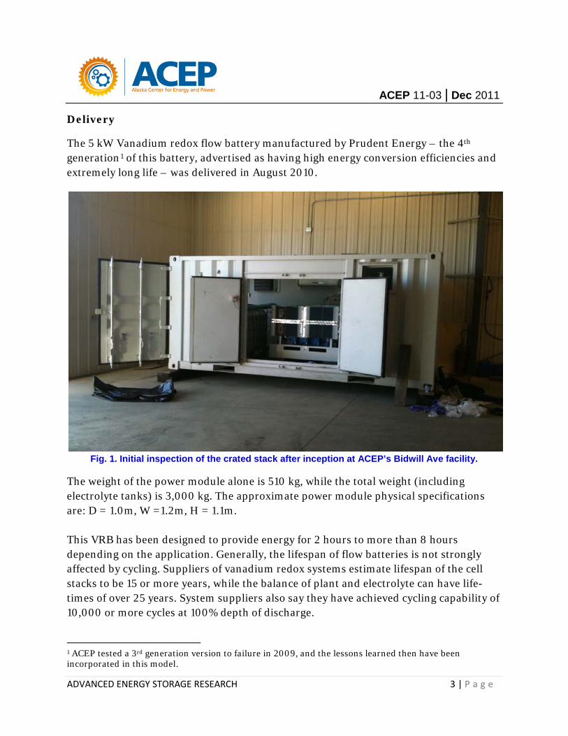
The 5 kW Vanadium redox flow battery manufactured by Prudent Energy – the 4th generation1 of this battery, advertised as having high energy conversion efficiencies and extremely long life – was delivered in August 2010.
Fig. 1. Initial inspection of the crated stack after inception at ACEP’s Bidwill Ave facility.
The weight of the power module alone is 510 kg, while the total weight (including electrolyte tanks) is 3,000 kg. The approximate power module physical specifications are: D = 1.0m, W =1.2m, H = 1.1m. This VRB has been designed to provide energy for 2 hours to more than 8 hours depending on the application. Generally, the lifespan of flow batteries is not strongly affected by cycling. Suppliers of vanadium redox systems estimate lifespan of the cell stacks to be 15 or more years, while the balance of plant and electrolyte can have life-times of over 25 years. System suppliers also say they have achieved cycling capability of 10,000 or more cycles at 100% depth of discharge. 1 ACEP tested a 3rd generation version to failure in 2009, and the lessons learned then have been incorporated in this model.
ACEP 11-03 | Dec 2011
ADVANCED ENERGY STORAGE RESEARCH 4 | P a g e
Commissioning
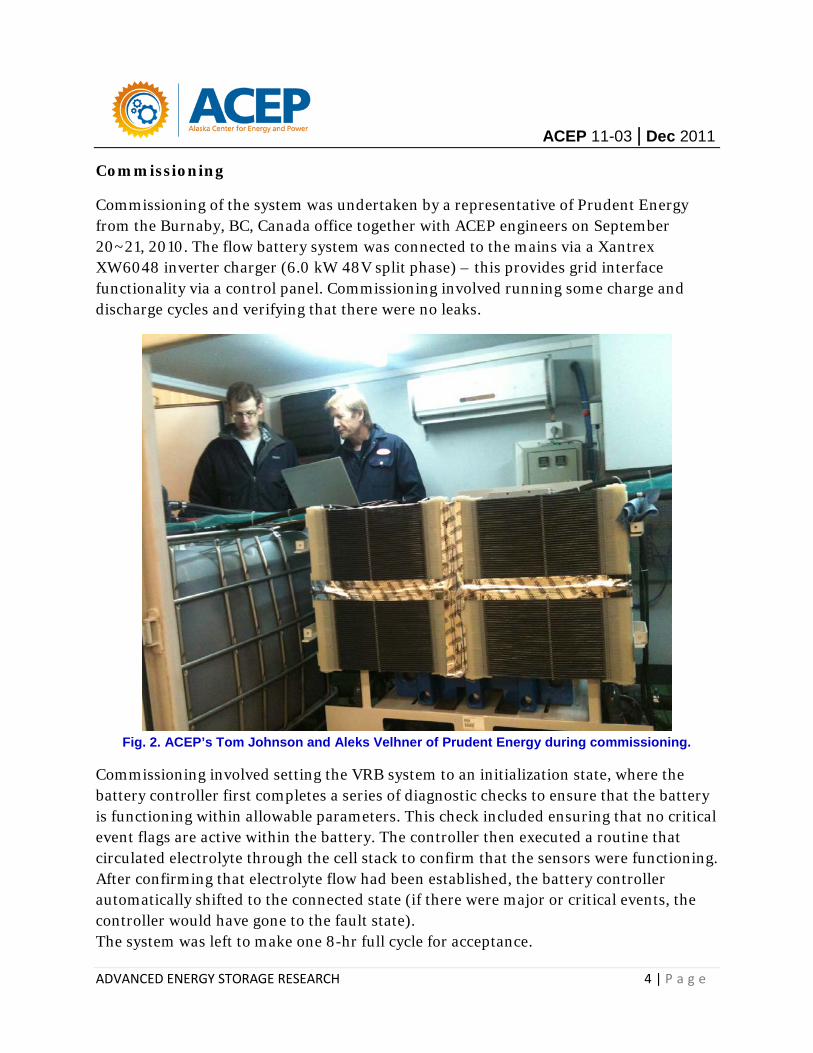
Commissioning of the system was undertaken by a representative of Prudent Energy from the Burnaby, BC, Canada office together with ACEP engineers on September 20~21, 2010. The flow battery system was connected to the mains via a Xantrex XW6048 inverter charger (6.0 kW 48V split phase) – this provides grid interface functionality via a control panel. Commissioning involved running some charge and discharge cycles and verifying that there were no leaks.
Fig. 2. ACEP’s Tom Johnson and Aleks Velhner of Prudent Energy during commissioning.
Commissioning involved setting the VRB system to an initialization state, where the battery controller first completes a series of diagnostic checks to ensure that the battery is functioning within allowable parameters. This check included ensuring that no critical event flags are active within the battery. The controller then executed a routine that circulated electrolyte through the cell stack to confirm that the sensors were functioning. After confirming that electrolyte flow had been established, the battery controller automatically shifted to the connected state (if there were major or critical events, the controller would have gone to the fault state). The system was left to make one 8-hr full cycle for acceptance.

ACEP 11-03 | Dec 2011
ADVANCED ENERGY STORAGE RESEARCH 5 | P a g e
Characterization: Performance Testing and Analysis
After commissioning, the battery system was instrumented and preliminary testing commenced – cycling with troubleshooting. The system did not come with data storage capability, thus it was necessary to have internet connectivity for data collection. ACEP developed the user interface program for analyzing data from the performance testing, as shown in Fig. 3. The VRB unit has several independent operating states that are automatically controlled through the battery controller’s state logic. Transitions between states occur because of either an external command from the operator or internal parameter changes observed by the battery’s process monitoring sensors.
Fig. 3. User interface. Schematic represents the flow battery system circuit (L). Remote PC display (R).
ACEP performed custom performance and safety testing with full data acquisition and analysis. The data shall is streamed live via an ftp address to designated access computers. Performance analyses have included:
• Cycle life • Discharge rate • Duty cycle • Environmental conditions (temperature).
Battery qualification is still an ongoing process that involves investigation of standby losses, capacity, etc. Some testing procedures e.g., accelerated life and storage analysis that typically involve deep cycling, have not been started. Overall, battery system performance specifications based on preliminary testing have shown very little deviation from the manufacturer specifications.
ACEP 11-03 | Dec 2011
ADVANCED ENERGY STORAGE RESEARCH 6 | P a g e
Previous Work
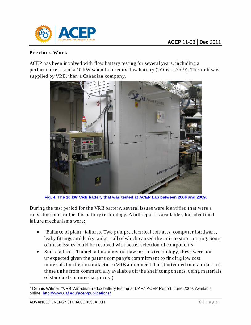
ACEP has been involved with flow battery testing for several years, including a performance test of a 10 kW vanadium redox flow battery (2006 – 2009). This unit was supplied by VRB, then a Canadian company.
Fig. 4. The 10 kW VRB battery that was tested at ACEP Lab between 2006 and 2009.
During the test period for the VRB battery, several issues were identified that were a cause for concern for this battery technology. A full report is available2, but identified failure mechanisms were:
• “Balance of plant” failures. Two pumps, electrical contacts, computer hardware, leaky fittings and leaky tanks – all of which caused the unit to stop running. Some of these issues could be resolved with better selection of components.
• Stack failures. Though a fundamental flaw for this technology, these were not unexpected given the parent company’s commitment to finding low cost materials for their manufacture (VRB announced that it intended to manufacture these units from commercially available off the shelf components, using materials of standard commercial purity.)
2 Dennis Witmer, “VRB Vanadium redox battery testing at UAF,” ACEP Report, June 2009. Available online: http://www.uaf.edu/acep/publications/
ACEP 11-03 | Dec 2011
ADVANCED ENERGY STORAGE RESEARCH 7 | P a g e
FUNDAMENTALS OF VANADIUM REDOX FLOW BATTERY SYSTEMS
Need for Energy Storage
Storage is essential for electricity consumers where power quality and reliability is critical, such as at airports, broadcasting operations, hospitals, financial services, data centers, telecommunications, and many finely tuned industrial processes. For grid systems that have a significant amount of renewable generation, a means to provide ancillary services is necessary to ensure power quality. Alaska has a number of isolated power systems that rely on diesel generators, wind turbines, or a combination of both. Hybrid wind-diesel systems, especially the high penetration types, require some spinning reserve component to ensure power quality. Generally speaking, it is relatively difficult for the conventional generator to keep good power quality in a closed grid because the generator output cannot follow the demand change quickly.
Developing the means to manage intermittent electricity generation from wind power farms has been a key challenge for grid operators. Whereas most power networks in the lower 48 have various solutions in dealing with grid imbalances caused by wind e.g., network interconnection and demand management, energy storage remains the most viable alternative for wind-diesel systems in Alaska. Storage also incurs energy losses, around 20-50% depending on the technology, which can put a dent in generating revenues. Energy loss during any of the conversion phases, as well as during storage, poses problems.
Energy storage technologies are not an alternative to any particular resource decision, but rather, a valuable adjunct to all resources, and they allow increased capacity to be derived from any given quantity of physical resources. The goal for energy storage technologies is to stockpile massive amounts of energy by transforming it into different but conveniently stored forms. Storage systems rely on three key components:
• An input energy-conversion module that receives energy from the grid and converts it to a storable form
• An energy-storage module that warehouses the energy, and • An output-conversion module that turns the stored energy back into electricity
and returns it to the grid.
Lead-acid batteries represent the most prevalent form of electric energy storage for residential, commercial and industrial customers wanting to maintain an uninterruptible power supply (UPS) system. However, storing massive amounts of energy from renewable resources requires rechargeable systems like flow batteries.
ACEP 11-03 | Dec 2011
ADVANCED ENERGY STORAGE RESEARCH 8 | P a g e
History of the Development of Flow Batteries
Flow batteries date back to the 19th century. They are best described as: ‘…a form of battery in which electrolyte containing one or more dissolved electro-active species flows through a power cell / reactor in which chemical energy is converted to electricity.
Full-scale development of the batteries started in the 1970s. The principle of the redox flow (RF) battery system was presented by L. H. Thaller of the National Aeronautics and Space Administration (NASA) in 19743. NASA mainly conducted research on the Fe/Cr system, discontinuing it in 1984 with the publication of the Final Report4. At the same time in Japan, the Electrotechnical Lab. (ETL; currently the National Institute of Advanced Industrial Science and Technology) was conducting basic research, and the development of the Fe/Cr system made progress as a project of the New Energy and Industrial Technology Development Organization (NEDO).
Flow batteries suitable for large scale energy storage have currently been developed at various organizations around the world. The Vanadium type of flow battery has become a mature technology – this is a rechargeable flow battery that employs vanadium redox couples in both half-cells, thereby eliminating the problem of cross contamination by diffusion of ions across the membrane. Although the use of vanadium redox couples in flow batteries had been suggested earlier by Pissoort5, by NASA researchers and by Pellegri and Spaziante6 in 1978, the first successful demonstration and commercial development was by Prof Maria Skyllas-Kazacos and co-workers at the University of New South Wales (UNSW) in Australia in the 1980's7,8. UNSW proceeded to develop the vanadium redox battery patented it9,10 – this resembled the present form (with sulfuric acid electrolytes). It is noteworthy that vanadium resources are abundantly available in Australia.
3 L. H. Thaller, “Electrically Rechargeable Redox Flow Cells,” Proc. Of the 9th IECEC, P.924 (1974). 4 N. H. Hagedorn, “NASA Redox Storage System Development Project Final Report,” DOE/NASA/12726-24, NASA TM-83677 (1984). 5 P. A. Pissoort, in FR Patent 754065 (1933). 6 A. Pelligri and P. M. Spaziante, in GB Patent 2030349 (1978), to Oronzio de Nori Impianti Elettrochimici S.p.A. 7 B. Sun, M. Skyllas-Kazacos, “A Study of the V(II)/V(III) Redox Couple for Redox Cell Application,” J. of Power Sources,15, P.179-190 (1985) 8 M. Rychcik and M. Skyllas-Kazacos, “Characteristics of a new all-vanadium redox flow battery,” Journal of Power Sources, 22, P.59-67, 1988. 9 M. Skyllas-Kazacos, M. Rychcik, and R. Robins, in AU Patent 575247 (1986), to Unisearch Ltd. 10 M. Skyllas-Kazacos, M. Rychick, R. Robins, All-vanadium redox bat tery, US Patent 4,786,567 (November 1988).
ACEP 11-03 | Dec 2011
ADVANCED ENERGY STORAGE RESEARCH 9 | P a g e
Vanadium Redox Flow Battery System
The word redox is a combination of, and thus stands for, reduction and oxidation. A redox battery refers to an electrochemical system that generates oxidation and reduction between two active materials, forming a redox system, on the surface of inactive electrodes. A redox flow battery has the electrolyte including these active materials in external containers, and charges and discharges electricity by supplying the electrolyte to the flow type cell by pumps or other means.
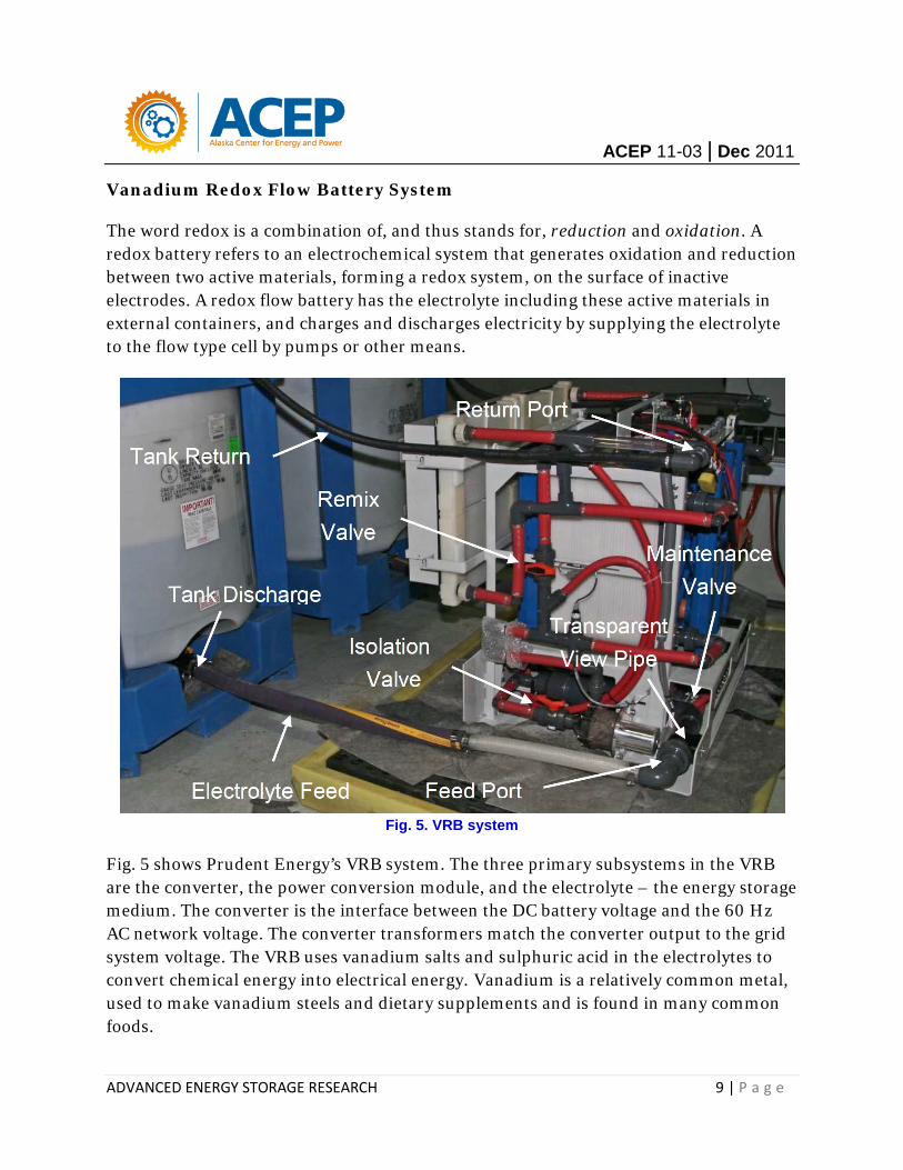
Fig. 5. VRB system
Fig. 5 shows Prudent Energy’s VRB system. The three primary subsystems in the VRB are the converter, the power conversion module, and the electrolyte – the energy storage medium. The converter is the interface between the DC battery voltage and the 60 Hz AC network voltage. The converter transformers match the converter output to the grid system voltage. The VRB uses vanadium salts and sulphuric acid in the electrolytes to convert chemical energy into electrical energy. Vanadium is a relatively common metal, used to make vanadium steels and dietary supplements and is found in many common foods.

ACEP 11-03 | Dec 2011
ADVANCED ENERGY STORAGE RESEARCH 10 | P a g e
Fig. 6. Construction of the cell stack (Courtesy SEI).
Generally the cells are grouped together in blocks known as stacks. In each stack the cells are connected electrically in series by bipolar plates, i.e. conducting plates that have positive electrolyte on one side and negative on the other. Each cell of a flow battery is practically identical, because they share the same electrolytes. Therefore, the stack voltage is the sum of the voltage of the individual cells. The main components of a cell stack are shown in Fig. 6. Fig. 7 is a schematic of the operation of the VRB. The philosophy of operation is based on the fact that when connected to the electrical network, the battery cells store energy through charging; this energy is later released to the power system during the discharge cycles – ideal for storage of excess generation from distributed resources (wind turbines).
During charging, electrolyte flow is forced across both sides of an ionic exchange membrane as electrical current is applied to the VRB-ESS cell stack. This results in an electrochemical reaction forcing protons to pass through the membrane causing a change in the vanadium valence. This change in valence represents stored chemical energy that can be recovered by reversing the process through the VRB-ESS cell stack. Control of flow conditions and electrical performance is automatically maintained by the battery controller.

ACEP 11-03 | Dec 2011
ADVANCED ENERGY STORAGE RESEARCH 11 | P a g e
Oxidation States
Fig. 8. Principle of the Vanadium Redox flow battery (Courtesy SEI).
Fig. 8 shows the concept of operation of the VRB. This consists of an assembly of power cells in which the two electrolyte solutions with a different ‘redox’ potential are kept separated by an ion exchange membrane. This membrane allows one electrolyte to ionize the other by exchanging electrons while preventing the two solutions to physically mix.
Both electrolytes are vanadium based – the electrolyte in the positive half-cells contains VO2+ and VO2+ ions, the electrolyte in the negative half-cells, V3+ and V2+ ions. The electrolytes are typically prepared by a number of processes, including electrolytically dissolving vanadium pentoxide (V2O5) in sulfuric acid (H2SO4). The solution remains strongly acidic in use. Both half-cells are additionally connected to storage tanks and pumps so that very large volumes of the electrolytes can be circulated through the cell.
Generally, metal ions that change valence can be used in a redox system, and the vanadium (V2+/V3+ – VO2+/VO2+) platform is among the best redox systems when such factors as energy density and economics are considered. The Vanadium redox battery exploits the ability of vanadium to exist in 4 different oxidation states, and uses this property to make a battery that has just one electroactive element instead of two.
ACEP 11-03 | Dec 2011
ADVANCED ENERGY STORAGE RESEARCH 12 | P a g e
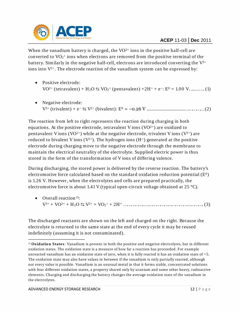
When the vanadium battery is charged, the VO2+ ions in the positive half-cell are converted to VO2+ ions when electrons are removed from the positive terminal of the battery. Similarly in the negative half-cell, electrons are introduced converting the V3+ ions into V2+. The electrode reaction of the vanadium system can be expressed by:
• Positive electrode: VO2+ (tetravalent) + H2O ⇆ VO2+ (pentavalent) +2H+ + e−: E0 = 1.00 V….....…. (1)
• Negative electrode: V3+ (trivalent) + e− ⇆ V2+ (bivalent): E0 = −0.26 V ……………………………………… (2)
The reaction from left to right represents the reaction during charging in both equations. At the positive electrode, tetravalent V ions (VO2+) are oxidized to pentavalent V ions (VO2+) while at the negative electrode, trivalent V ions (V3+) are reduced to bivalent V ions (V2+). The hydrogen ions (H+) generated at the positive electrode during charging move to the negative electrode through the membrane to maintain the electrical neutrality of the electrolyte. Supplied electric power is thus stored in the form of the transformation of V ions of differing valence.
During discharging, the stored power is delivered by the reverse reaction. The battery’s electromotive force calculated based on the standard oxidation reduction potential (E0) is 1.26 V. However, when the electrolytes and cells are prepared practically, the electromotive force is about 1.41 V (typical open-circuit voltage obtained at 25 °C).
• Overall reaction11: V3+ + VO2+ + H2O ⇆ V2+ + VO2+ + 2H+ ……………..………………………………………. (3)
The discharged reactants are shown on the left and charged on the right. Because the electrolyte is returned to the same state at the end of every cycle it may be reused indefinitely (assuming it is not contaminated). 11 Oxidation States: Vanadium is present in both the positive and negative electrolytes, but in different oxidation states. The oxidation state is a measure of how far a reaction has proceeded. For example unreacted vanadium has an oxidation state of zero, when it is fully reacted it has an oxidation state of +5. The oxidation state may also have values in between if the vanadium is only partially reacted, although not every value is possible. Vanadium is an unusual metal in that it forms stable, concentrated solutions with four different oxidation states, a property shared only by uranium and some other heavy, radioactive elements. Charging and discharging the battery changes the average oxidation state of the vanadium in the electrolytes.

RR XX-XX | Dec 2011
Analysis CHARACTERIZATION/PERFORMANCE TESTING
Characteristics of the 5 Kw, 20 kWh Vanadium Redox Flow Battery
As per the project objectives, performance testing was undertaken to verify manufacturer performance claims in a controlled environment with managed charge/discharge cycles, and to determine if any significant maintenance issues exist. It is important to mention that the battery was not subjected to rigorous tests that would otherwise test the limits of performance
Fig. 5 kW Prudent Energy Battery (without electrolyte tanks).
The quantities used in validating the battery system include:
• Efficiency (power converter efficiency, cell stacks efficiency, overall efficiency) • Auxiliary power consumption; other storage losses • Storage capacity and State of Charge • Starting and stopping ; response time and transients • Degradation.
ACEP 11-03 | Dec 2011
ADVANCED ENERGY STORAGE RESEARCH 2 | P a g e
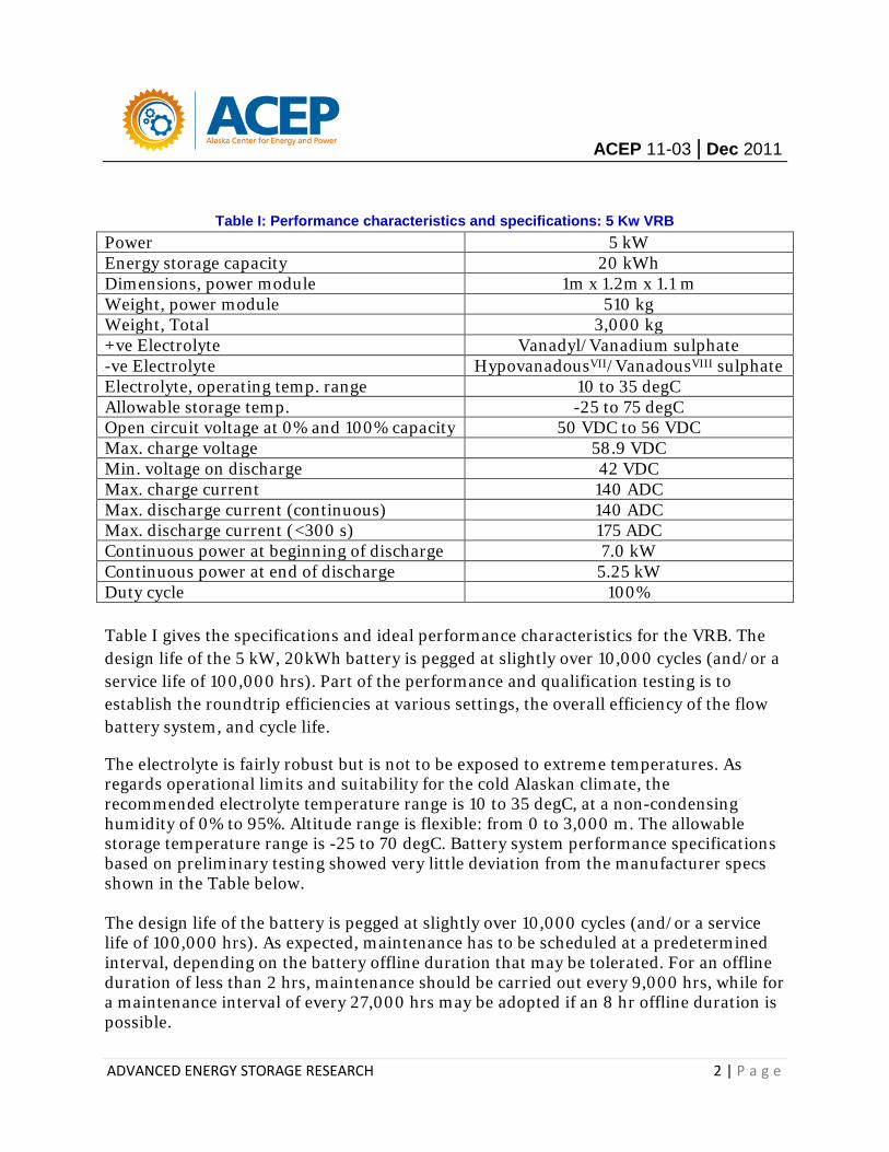
Table I: Performance characteristics and specifications: 5 Kw VRB Power 5 kW Energy storage capacity 20 kWh Dimensions, power module 1m x 1.2m x 1.1 m Weight, power module 510 kg Weight, Total 3,000 kg +ve Electrolyte Vanadyl/Vanadium sulphate -ve Electrolyte HypovanadousVII/VanadousVIII sulphate Electrolyte, operating temp. range 10 to 35 degC Allowable storage temp. -25 to 75 degC Open circuit voltage at 0% and 100% capacity 50 VDC to 56 VDC Max. charge voltage 58.9 VDC Min. voltage on discharge 42 VDC Max. charge current 140 ADC Max. discharge current (continuous) 140 ADC Max. discharge current (<300 s) 175 ADC Continuous power at beginning of discharge 7.0 kW Continuous power at end of discharge 5.25 kW Duty cycle 100%
Table I gives the specifications and ideal performance characteristics for the VRB. The design life of the 5 kW, 20kWh battery is pegged at slightly over 10,000 cycles (and/or a service life of 100,000 hrs). Part of the performance and qualification testing is to establish the roundtrip efficiencies at various settings, the overall efficiency of the flow battery system, and cycle life.
The electrolyte is fairly robust but is not to be exposed to extreme temperatures. As regards operational limits and suitability for the cold Alaskan climate, the recommended electrolyte temperature range is 10 to 35 degC, at a non-condensing humidity of 0% to 95%. Altitude range is flexible: from 0 to 3,000 m. The allowable storage temperature range is -25 to 70 degC. Battery system performance specifications based on preliminary testing showed very little deviation from the manufacturer specs shown in the Table below. The design life of the battery is pegged at slightly over 10,000 cycles (and/or a service life of 100,000 hrs). As expected, maintenance has to be scheduled at a predetermined interval, depending on the battery offline duration that may be tolerated. For an offline duration of less than 2 hrs, maintenance should be carried out every 9,000 hrs, while for a maintenance interval of every 27,000 hrs may be adopted if an 8 hr offline duration is possible.
ACEP 11-03 | Dec 2011
ADVANCED ENERGY STORAGE RESEARCH 3 | P a g e
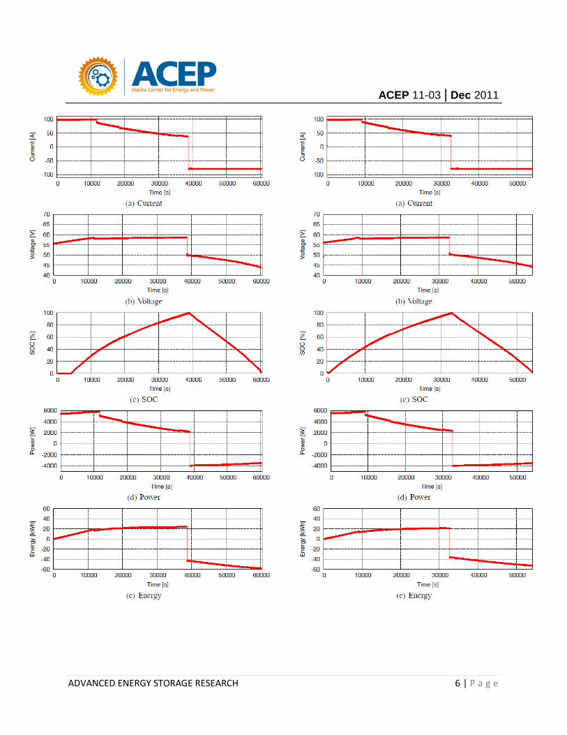
Charge and Discharge Parameters for Test #50
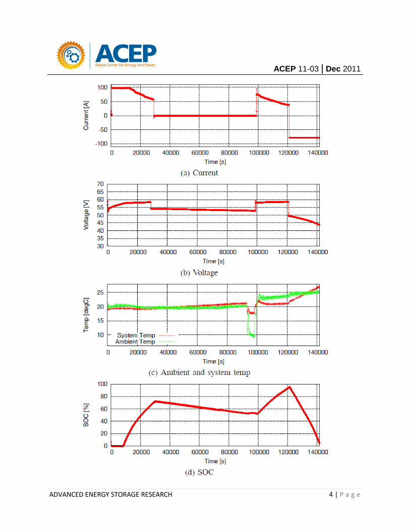
Fig. XX shows results for test no. 50 conducted for about 40 hours continuously (between 3/24/2011 10:06:53 and 3/26/2011 01:27:21). The battery was on charge for about 8 hours, when it attained a peak voltage of 58.361 V. It was then left to discharge by feeding power back to the grid for another 19.4 hours, after which charging was resumed at the minimum set value for the state of charge (SOC) at 52% – this was arbitrarily set to monitor other parameters. There have been instances when the charge voltage has attained the maximum value of 58.9 V. It can be observed that under normal conditions the battery operates as per the specifications detailed in Table II. Generally the FBESS has been performing well since its commissioning. It is seen from Figs. XX(c) and (d) that with time, the system temperature tends to rise with each successive discharge of the battery. The system has a self-regulatory power conditioning system that stabilizes this situation to ensure the limits of electrolyte operating temperature are respected. Fig. XX shows that when linked to the grid, the FBESS operates within specified limits in Table II, and more importantly, seamlessly draws power from, and discharges back to the network at the right frequency and with minimal losses. The essence of the performance testing is to verify that aside from large installations that require storage (load shifting), cascaded use of this battery technology may be implemented. This involves utilizing the flow batteries for more than one application, e.g., UPS, electric vehicle charging, laptop charging station, and efficient energy storage at minutes to hours duration to firm ramping balance. These results are just a synopsis of a few trial runs but are representative of the capability of the technology to charge and discharge appropriately when integrated with a power system. Rate of charge can be set by the operator, based on either voltage or SOC levels. Based on the expected life time costs, the FBESS offers an attractive solution with both economic and technical benefits for an installation in Alaska, in the form of peak shaving/load balancing, where spikes of demand are met by the battery; stand-alone off-grid power system that could meet remote area energy requirements; and back-up power solution to protect sensitive systems.
ACEP 11-03 | Dec 2011
ADVANCED ENERGY STORAGE RESEARCH 4 | P a g e
ACEP 11-03 | Dec 2011
ADVANCED ENERGY STORAGE RESEARCH 5 | P a g e
Charge and Discharge Parameters for Test #51 and #52
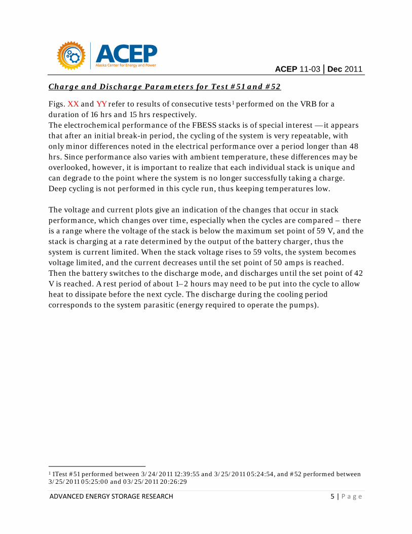
Figs. XX and YY refer to results of consecutive tests1 performed on the VRB for a duration of 16 hrs and 15 hrs respectively. The electrochemical performance of the FBESS stacks is of special interest — it appears that after an initial break-in period, the cycling of the system is very repeatable, with only minor differences noted in the electrical performance over a period longer than 48 hrs. Since performance also varies with ambient temperature, these differences may be overlooked, however, it is important to realize that each individual stack is unique and can degrade to the point where the system is no longer successfully taking a charge. Deep cycling is not performed in this cycle run, thus keeping temperatures low. The voltage and current plots give an indication of the changes that occur in stack performance, which changes over time, especially when the cycles are compared – there is a range where the voltage of the stack is below the maximum set point of 59 V, and the stack is charging at a rate determined by the output of the battery charger, thus the system is current limited. When the stack voltage rises to 59 volts, the system becomes voltage limited, and the current decreases until the set point of 50 amps is reached. Then the battery switches to the discharge mode, and discharges until the set point of 42 V is reached. A rest period of about 1–2 hours may need to be put into the cycle to allow heat to dissipate before the next cycle. The discharge during the cooling period corresponds to the system parasitic (energy required to operate the pumps).
1 1Test #51 performed between 3/24/2011 12:39:55 and 3/25/2011 05:24:54, and #52 performed between 3/25/2011 05:25:00 and 03/25/2011 20:26:29
ACEP 11-03 | Dec 2011
ADVANCED ENERGY STORAGE RESEARCH 6 | P a g e
ACEP 11-03 | Dec 2011
ADVANCED ENERGY STORAGE RESEARCH 7 | P a g e
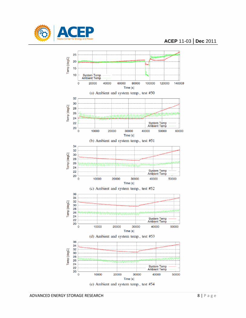
Ambient and System temperature: Tests #50 - 54
Fig. XX shows the progression in the system temperature over the 4-day operation. The experiments are carried out in a controlled facility, thus there is little deviation in the ambient temperature. As expected, the system temperature tends to rise with time, but more so with the discharge cycle. By Arrhenius Law, the rate at which the chemical reaction proceeds increases exponentially as temperature rises, allowing more instantaneous power to be extracted from the battery — higher temperatures improve ion mobility reducing the cell’s internal impedance and increasing its capacity. However, thermal management is necessary so that both charge capacity and cycle life can be optimized since high temperatures may also initiate irreversible chemical reactions that can cause permanent damage or complete failure of the battery. Typically, the temperature of the electrolyte is managed internally by the VRB-ESS. There are two issues worth mention: at high temperatures (say above 40 degC which is NOT an Alaskan concern) and at low temperatures say below 10 degC which is an Alaskan concern. At low temperatures the electrolyte must be warmed, and this is accomplished automatically if the system is operating (cycling). The reason for this is not so much a case of freezing since the electrolyte does not freeze until below about -20 degC, but is more a case of viscosity. It is hard to pump the thicker electrolyte given the pump designs in use. Generally the capacity of the system is not affected by the cold. If it is extremely cold then the system has to be designed for it. Similarly, in very hot climates the system must be so designed as to cool the electrolyte to below 40 degC (105 degF).
ACEP 11-03 | Dec 2011
ADVANCED ENERGY STORAGE RESEARCH 8 | P a g e
ACEP 11-03 | Dec 2011
ADVANCED ENERGY STORAGE RESEARCH 9 | P a g e
Efficiecy and Life-Cycle
Efficiency and cycle life are two important parameters to consider along with other parameters before selecting a storage technology. Both of these parameters affect the overall storage cost: low efficiency increases the effective energy cost as only a fraction of the stored energy can be utilized, while low cycle life also increases the total cost as the storage device needs to be replaced more often. The present values of these expenses need to be considered along with the capital cost and operating expenses to obtain a better picture of the total ownership cost for a storage technology.

ACEP 11-03 | Dec 2011
ADVANCED ENERGY STORAGE RESEARCH 1 | P a g e
Perspectives VRB FOR ALASKA?
Cost Considerations
Fig. XX. Major cost components of the energy storage system: the power conversion unit ($/kW), and the storage unit ($/kWh). The balance of plant is typically costed with the storage unit.
It’s hard to sort out the cost of electricity stored by flow batteries, because there are too many variables. Nonetheless, indications are favorable. Witmer1 calculates that providing electricity using VRBs, assuming 15,000 charge–discharge cycles, should cost 10 U.S. cents per kilowatt-hour—the more cycles, though, the lower the cost per kilowatt-hour. That would definitely prove competitive in off-grid Alaskan villages, where the rising cost of oil has pushed the fuel cost of diesel-fired electricity to around 16 to 17 cents per kilowatt-hour. In general, present worth is based on ownership of the device over 10 years for a given application and includes the following factors:
1 Dennis Witmer

ACEP 11-03 | Dec 2011
ADVANCED ENERGY STORAGE RESEARCH 2 | P a g e
• Efficiency • Cycle Life • Initial Capital Costs • Operations and Maintenance • Storage-device Replacement
Thus the present worth (or present value) calculation includes not only capital cost, but operating costs as well. The most important characteristics include round-trip electrical energy efficiency (kWh out/kWh in) and cycle life. Because cycle life, or number of 8 discharges before replacement is required, is an important cost driver, the use of the system, as defined by the planned application, must be considered.
Cost is calculated for a system by adding the cost of the storage unit and the power conditioning system. These subsystems are treated separately because they provide different functions and are priced by different ratings. Power components are priced in $/kW. Energy storage units are priced in $/kWh. For this reason, the individual subsystem costs are needed, although they are often difficult to separate from vendor system prices. The values used in this update are listed in Table 4, along with references. The costs in Table XX are based on certain standard assumptions for the applications and technologies considered, and on expert opinion. They are meant to be used for comparative purposes. The actual costs of any storage system depend on many factors and the assumptions and means of calculating some of the values used are subjective.
Table: Cost and Performance Assumptions2
Technology
Cost Round-
trip Efficiency
%
Cycles
Power Subsystem
$/kW
Energy Storage
Subsystem $/kWh
Advanced Lead-acid Batteries (2000 cycle life) 400 330 80 2000 Sodium/sulfur Batteries 350 350 75 3000 Lead-acid Batteries (w/Carbon-enhanced Electrodes) 400 330 75 20000 Zinc/bromine Batteries 400 400 70 3000 Vanadium Redox Batteries 400 600 65 5000 Lithium-ion Batteries (large) 400 600 85 4000 CAES 700 5 N/A (70) 25000 Pumped hydro 1200 75 85 25000 Flywheels (high speed composite) 600 1600 95 25000 Supercapacitors 500 10000 95 25000 2 SANDIA Report: Energy Storage Systems Cost Update – A Study for the DOE Energy Storage Systems Program, SAND2011-2730, April 2011.
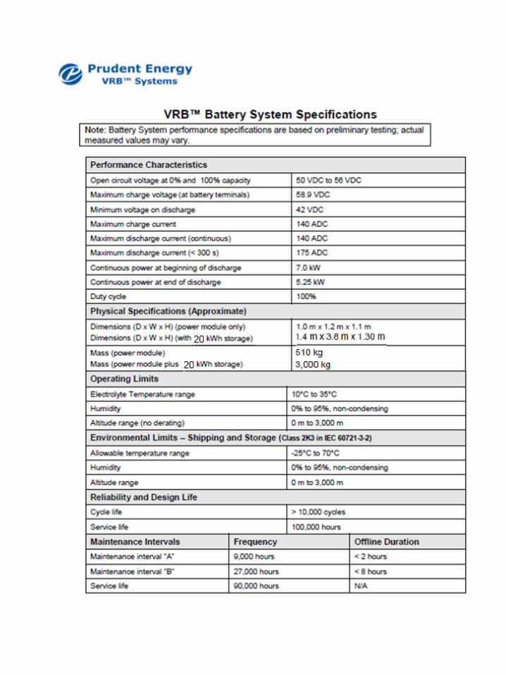
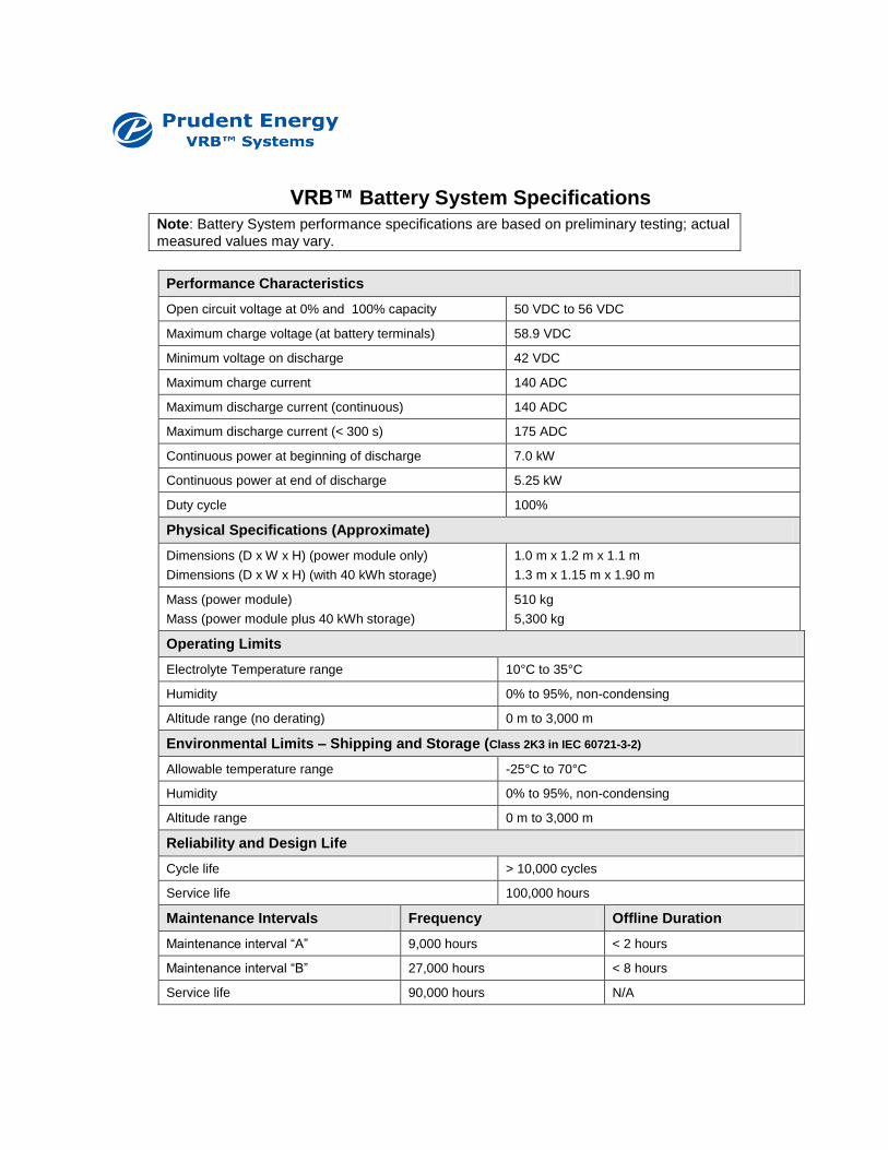
VRB™ Battery System Specifications
Note: Battery System performance specifications are based on preliminary testing; actual
measured values may vary.
Performance Characteristics
Open circuit voltage at 0% and 100% capacity 50 VDC to 56 VDC
Maximum charge voltage (at battery terminals) 58.9 VDC
Minimum voltage on discharge 42 VDC
Maximum charge current 140 ADC
Maximum discharge current (continuous) 140 ADC
Maximum discharge current (< 300 s) 175 ADC
Continuous power at beginning of discharge 7.0 kW
Continuous power at end of discharge 5.25 kW
Duty cycle 100%
Physical Specifications (Approximate)
Dimensions (D x W x H) (power module only)
Dimensions (D x W x H) (with 40 kWh storage)
1.0 m x 1.2 m x 1.1 m
1.3 m x 1.15 m x 1.90 m
Mass (power module)
Mass (power module plus 40 kWh storage)
510 kg
5,300 kg
Operating Limits
Electrolyte Temperature range 10°C to 35°C
Humidity 0% to 95%, non-condensing
Altitude range (no derating) 0 m to 3,000 m
Environmental Limits – Shipping and Storage (Class 2K3 in IEC 60721-3-2)
Allowable temperature range -25°C to 70°C
Humidity 0% to 95%, non-condensing
Altitude range 0 m to 3,000 m
Reliability and Design Life
Cycle life > 10,000 cycles
Service life 100,000 hours
Maintenance Intervals Frequency Offline Duration
Maintenance interval “A” 9,000 hours < 2 hours
Maintenance interval “B” 27,000 hours < 8 hours
Service life 90,000 hours N/A

Advanced Battery Storage Systems Testing at ACEP
5 kW, 20 kWh PRUDENT ENERGY VRB-ESS
ACEP ENERGY STORAGE RESEARCH