the 0rqb-d0w12l is an isolated dc/dc converter that ... · the 0rqb-d0w12l is an isolated dc/dc...
TRANSCRIPT
0RQB-D0W12L Isolated DC-DC Converter
belfuse.com/power-solutions
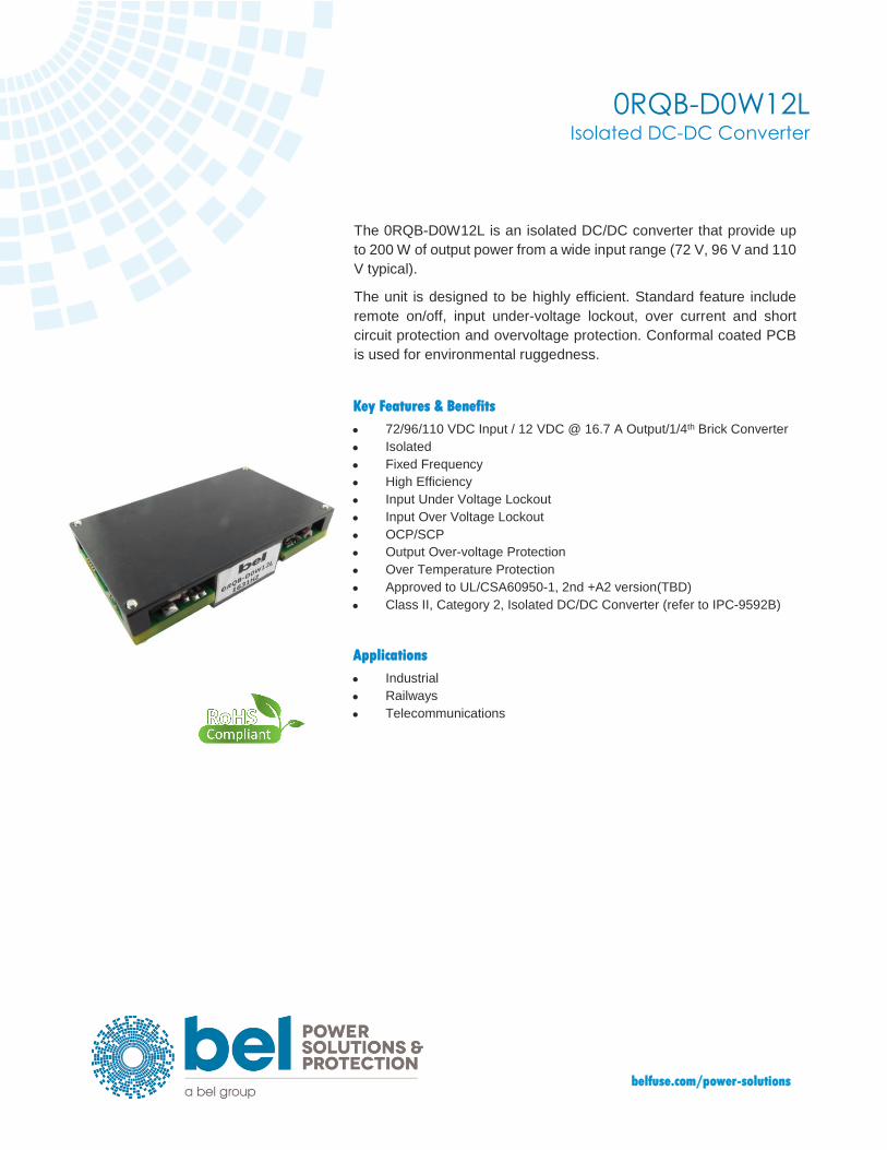
The 0RQB-D0W12L is an isolated DC/DC converter that provide up
to 200 W of output power from a wide input range (72 V, 96 V and 110
V typical).
The unit is designed to be highly efficient. Standard feature include
remote on/off, input under-voltage lockout, over current and short
circuit protection and overvoltage protection. Conformal coated PCB
is used for environmental ruggedness.
Key Features & Benefits
• 72/96/110 VDC Input / 12 VDC @ 16.7 A Output/1/4th Brick Converter
• Isolated
• Fixed Frequency
• High Efficiency
• Input Under Voltage Lockout
• Input Over Voltage Lockout
• OCP/SCP
• Output Over-voltage Protection
• Over Temperature Protection
• Approved to UL/CSA60950-1, 2nd +A2 version(TBD)
• Class II, Category 2, Isolated DC/DC Converter (refer to IPC-9592B)
Applications
• Industrial
• Railways
• Telecommunications
2
0RQB-D0W12L
belfuse.com/power-solutions
1. MODEL SELECTION
MODEL NUMBER
OUTPUT VOLTAGE
INPUT VOLTAGE
MAX. OUTPUT CURRENT
MAX. OUTPUT POWER
TYPICAL EFFICIENCY
0RQB-D0W12L 12 VDC 72/96/110V VDC 16.7 A 200 W 93%
NOTE: Add “G” suffix at the end of the model number to indicate Tray Packaging.
PART NUMBER EXPLANATION
0 R QB - D0 W 12 L x
Mounting Type RoHS Status
Series Name Output Power
Input Range
Output Voltage
Active Logic Package Type
Through hole mount
RoHS DOSA
Quarter Brick 200 W 72/96/110V 12 V Active low, without HSK
G – Tray package
2. ABSOLUTE MAXIMUM RATINGS
PARAMETER DESCRIPTION MIN TYP MAX UNITS
Continuous non-operating Input Voltage -0.5 - 164 V
Remote On/Off -0.3 - 15 V
Current Sink 0 - 10 mA
Isolation voltage Input to output - - 2250 V
Operating Temperature Temperature measured at the center of the
baseplate, full load -40 - 95 C
Thermal resistance - 0.3 - C/W
Storage Temperature -55 - 125 C
Altitude - - 2000 m
NOTE: Ratings used beyond the maximum ratings may cause a reliability degradation of the converter or may permanently damage the device.
3. INPUT SPECIFICATIONS
All specifications are typical at 25°C unless otherwise stated.
PARAMETER DESCRIPTION MIN TYP MAX UNIT
Operating Input Voltage 1 Fully functioning for long term operation. 50 - 137.5 V
Operating Input Voltage 2 Fully functioning for 100ms operation. 43 - 50 V
Operating Input Voltage 3 Fully functioning for 100ms operation. Full function is not guaranteed but undamaged for 1s operation.
137.5 156 V
Input Current (full load) - - 5.7 A
Input Current (no load) - 50 - mA
Remoted Off Input Current - 2 5 mA
Input Reflected Ripple Current (rms) - 20 - mA
Input Reflected Ripple Current (pk-pk) - 50 - mA
Under-voltage Turn on Threshold Turn on Threshold 46 47 49 V
Under-voltage Turn off Threshold Turn off Threshold, non-latching 40 41 42.5 V
Over-voltage Shutdown Threshold Auto-recovery and non-latching. 161 163 165 V
Over-voltage Recovery Threshold 154 155 156 V

0RQB-D0W12L 3
Asia-Pacific
+86 755 298 85888 Europe, Middle East
+353 61 225 977 North America
+1 408 785 5200
© 2019 Bel Power Solutions & Protection Rev. AG
4. OUTPUT SPECIFICATIONS
All specifications are typical at nominal input, full load at 25°C unless otherwise stated.
PARAMETER DESCRIPTION MIN TYP MAX UNIT
Output Voltage Set Point Test condition of the output setpoint: Vin=110V, Io=100% load at 25°C ambient.
11.76 12 12.24 V
Load Regulation - - ±30 mV
Line Regulation - - ±30 mV
Regulation Over Temperature - ±60 ±200 mV
Ripple and Noise (pk-pk) 40KHz-100MHz BW, with 1µF ceramic capacitor and 220uF bulk electrolytic at output.
- - 250 mV Ripple and Noise (rms) - - 50 mV
Output Current Range 0 - 16.7 A
Output DC Current Limit Enter a hiccup mode, non-latching. 18 20 22 A
Rise time Vin=110V, Io=16.7A, with 1µF ceramic capacitor and 220uF bulk electrolytic at output.
- - 200 ms
Start-up time 300 500 ms
Overshoot at Turn on - 0 3 %
Undershoot at Turn off - 0 3 %
Output Capacitance 220 - 5000 uF
Transient Response
△V 50%~75% Load
di/dt=0.1A/us, with 1µF ceramic capacitor and 220uF bulk electrolytic at output.
- - 600 mV
Settling Time - - 2 ms
△V 75%~50% Load - - 600 mV
Settling Time - - 2 ms
5. GENERAL SPECIFICATIONS
PARAMETER DESCRIPTION MIN TYP MAX UNIT
Efficiency Io=60% Irate – 100% Irate
TA = 25°C 92 93 -
% Io=40% Irate - 60% Irate 90 92 -
Switching Frequency - 250 - kHz
Output Voltage Trim Range 10.8 - 13.2 V
Over Temperature Protection Temperature measured at the center of the baseplate, full load
- 110 - ℃
Output Over Voltage Protection Enter a latching. non-hiccup mode - - 15 V
Weight - 69 - g
FIT Calculated Per Bell Core SR-332 (Vin=110 V, Vo=12V, Io=13A, Ta = 25°C, FIT=109/MTBF)
- 190.48 - -
MTBF - 5.25 - Mhrs
Dimensions Inches (L × W × H) Millimeters (L × W × H)
2.45 x 1.45x 0.59 62.24 x 36.84 x15
Inches Millimeters
Isolation Characteristics
Input to Output - - 2250 Vdc
Input to Heatsink - - 2250 Vdc
Output to Heatsink - - 2250 Vdc
Isolation Resistance 10M - - Ohm
Isolation Capacitance - 2200 - pF
4
0RQB-D0W12L
belfuse.com/power-solutions
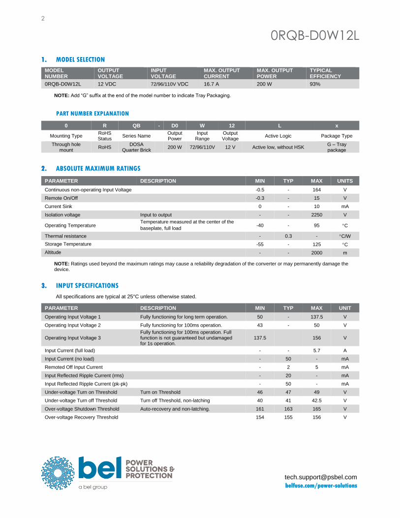
6. EFFICIENCY DATA
70.0%
75.0%
80.0%
85.0%
90.0%
95.0%
1.67 3.34 5.01 6.68 8.35 10.0211.6913.3615.03 16.7
EF
FIC
IEN
CY
OUTPUT CURRENT(A)
50V
66V
110
V
0RQB-D0W12L 5
Asia-Pacific
+86 755 298 85888 Europe, Middle East
+353 61 225 977 North America
+1 408 785 5200
© 2019 Bel Power Solutions & Protection Rev. AG
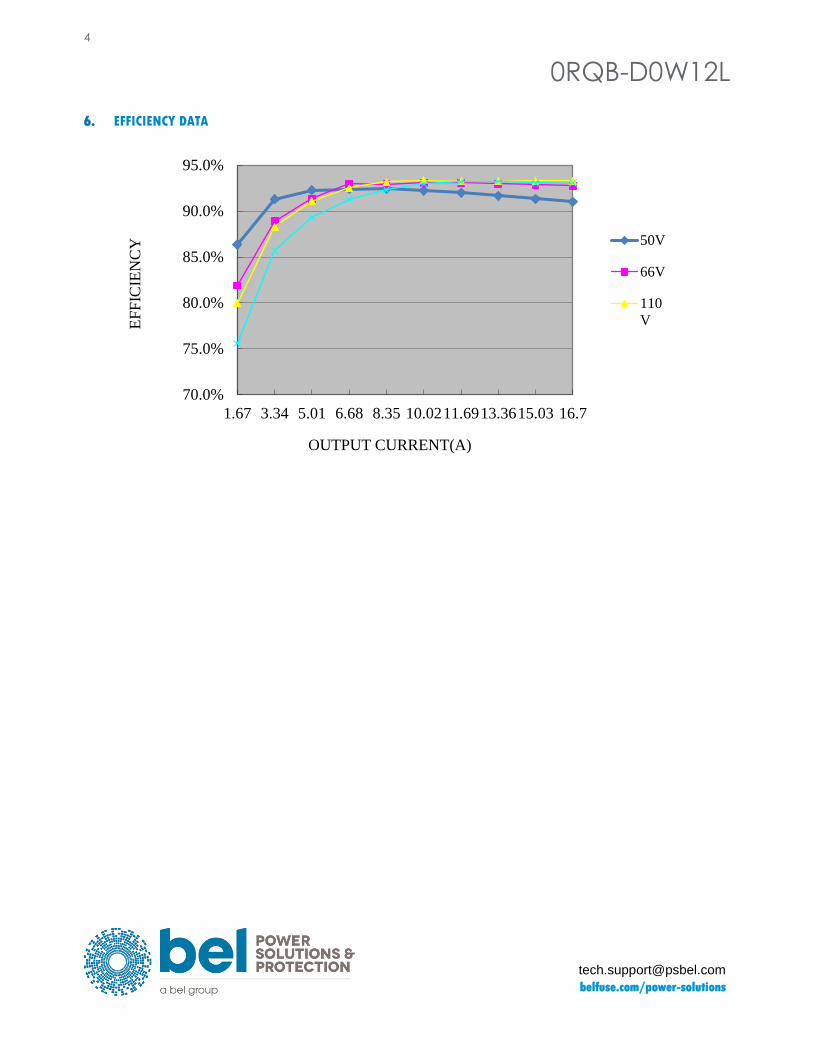
7. REMOVE ON/OFF
PARAMETER DESCRIPTION MIN TYP MAX UNIT
Signal Low (Unit On) Active Low Remote On/Off pin is open, the module is off
-0.3 - 0.8 V
Signal High (Unit Off) 2.4 - 18 V
Current Sink 0 - 1 mA
Recommended Remote On/Off Circuit for Active Low
Control with open collector/drain circuit Control with photocoupler circuit
Control with logic circuit Permanently on
Vin+
Vin-
On/off
Vin+
Vin-
On/off
Vin+
Vin-
On/off
VccVin+
Vin-
On/off
6
0RQB-D0W12L
belfuse.com/power-solutions
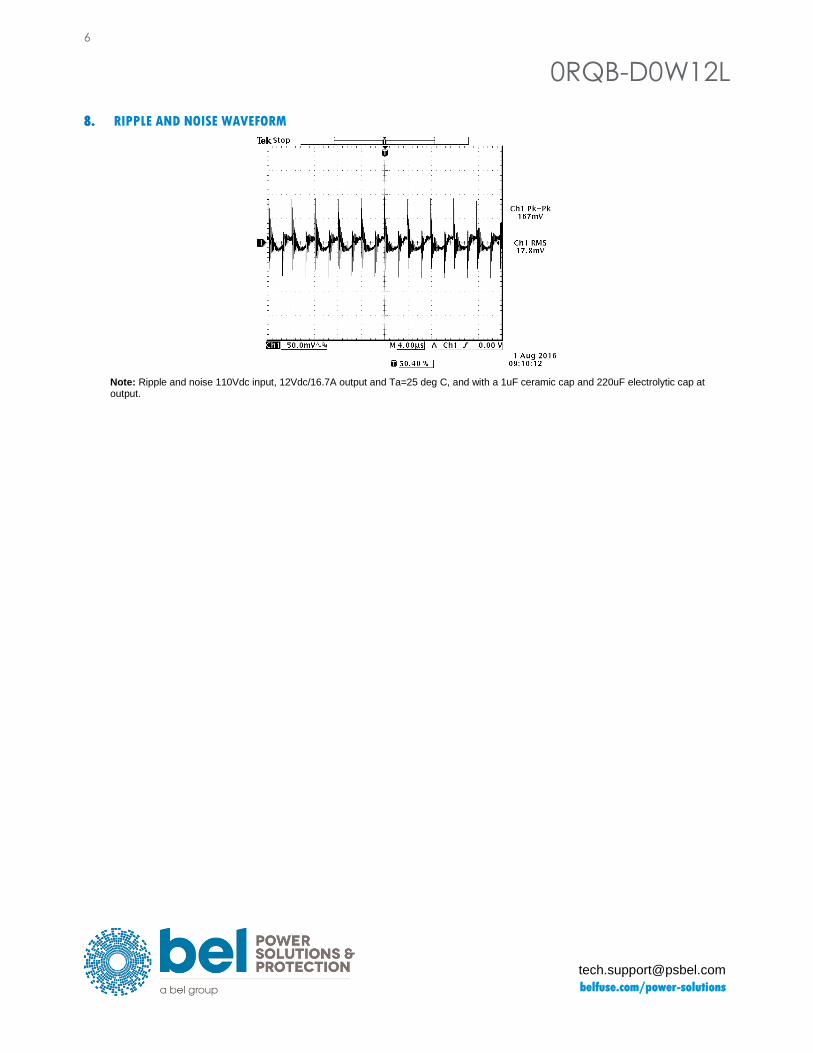
8. RIPPLE AND NOISE WAVEFORM
Note: Ripple and noise 110Vdc input, 12Vdc/16.7A output and Ta=25 deg C, and with a 1uF ceramic cap and 220uF electrolytic cap at output.
0RQB-D0W12L 7
Asia-Pacific
+86 755 298 85888 Europe, Middle East
+353 61 225 977 North America
+1 408 785 5200
© 2019 Bel Power Solutions & Protection Rev. AG
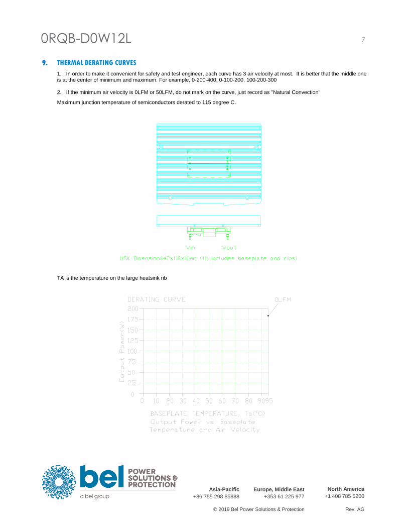
9. THERMAL DERATING CURVES
1. In order to make it convenient for safety and test engineer, each curve has 3 air velocity at most. It is better that the middle one is at the center of minimum and maximum. For example, 0-200-400, 0-100-200, 100-200-300 2. If the minimum air velocity is 0LFM or 50LFM, do not mark on the curve, just record as "Natural Convection"
Maximum junction temperature of semiconductors derated to 115 degree C.
TA is the temperature on the large heatsink rib

8
0RQB-D0W12L
belfuse.com/power-solutions
10. TRANSIENT RESPONSE WAVEFORMS
Transient Response: di/dt=0.1A/us, 1uF ceramic cap and 220uF electrolytic cap at output.
Vout= 12V 50%-75% Load Transients at Vin=110V, Ta=25 deg C Vout= 12V 75%-50% Load Transients at Vin=110V, Ta=25 deg C
0RQB-D0W12L 9
Asia-Pacific
+86 755 298 85888 Europe, Middle East
+353 61 225 977 North America
+1 408 785 5200
© 2019 Bel Power Solutions & Protection Rev. AG
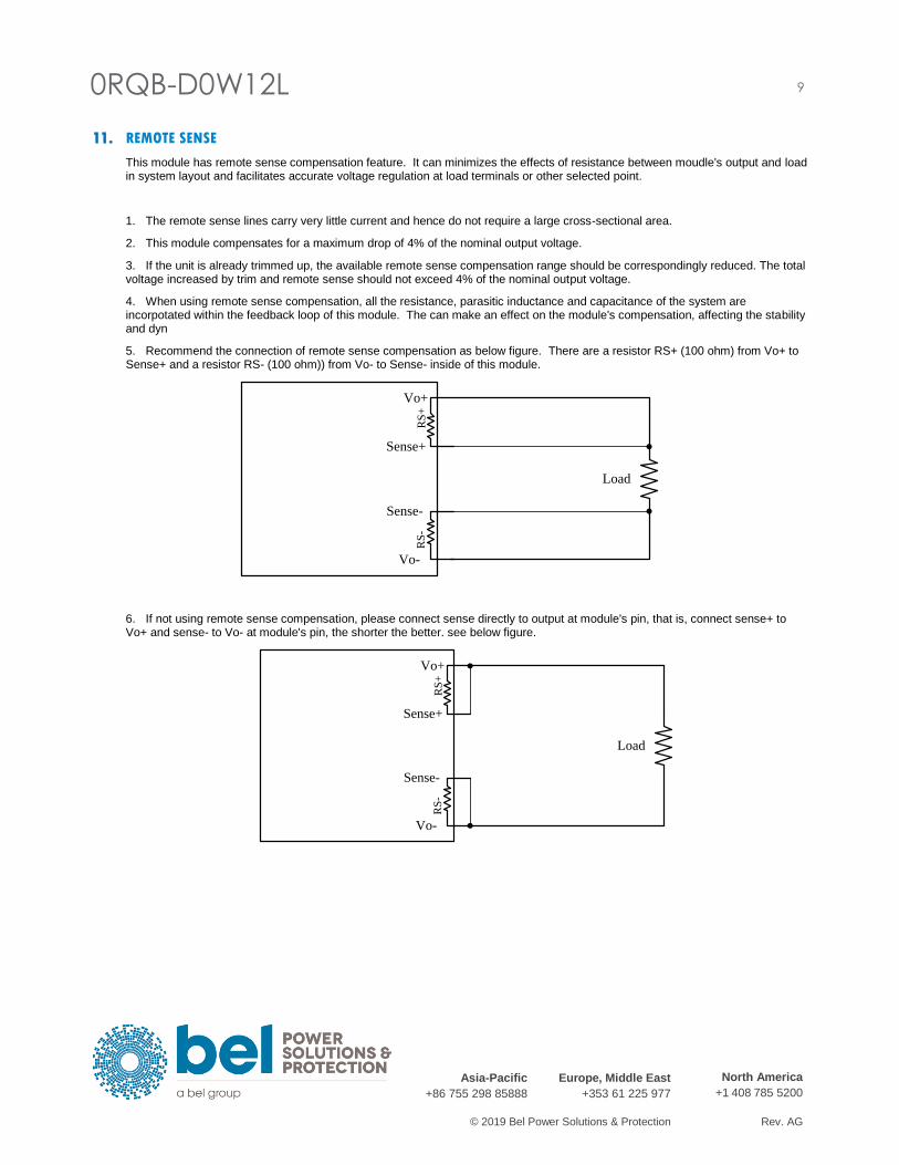
11. REMOTE SENSE
This module has remote sense compensation feature. It can minimizes the effects of resistance between moudle's output and load in system layout and facilitates accurate voltage regulation at load terminals or other selected point.
1. The remote sense lines carry very little current and hence do not require a large cross-sectional area.
2. This module compensates for a maximum drop of 4% of the nominal output voltage.
3. If the unit is already trimmed up, the available remote sense compensation range should be correspondingly reduced. The total voltage increased by trim and remote sense should not exceed 4% of the nominal output voltage.
4. When using remote sense compensation, all the resistance, parasitic inductance and capacitance of the system are incorpotated within the feedback loop of this module. The can make an effect on the module's compensation, affecting the stability and dyn
5. Recommend the connection of remote sense compensation as below figure. There are a resistor RS+ (100 ohm) from Vo+ to Sense+ and a resistor RS- (100 ohm)) from Vo- to Sense- inside of this module.
6. If not using remote sense compensation, please connect sense directly to output at module's pin, that is, connect sense+ to Vo+ and sense- to Vo- at module's pin, the shorter the better. see below figure.
Sense+
Sense-
RS
-
Vo-
Vo+
RS
+
Load
Sense+
Sense-
RS
-
Vo-
Vo+
RS
+
Load

10
0RQB-D0W12L
belfuse.com/power-solutions
12. OVER CURRENT PROTECTION
To provide protection in a fault output overload condition, the module is equipped with internal current-limiting circuitry and can
endure current limiting for a few mili-seconds. If the overcurrent condition persists beyond a few milliseconds, the module will shut
down into hiccup mode and restart once every 800mS. The module operates normally when the output current goes into specified
range. The typical average output current is 0.51A during hiccup.
0RQB-D0W12L 11
Asia-Pacific
+86 755 298 85888 Europe, Middle East
+353 61 225 977 North America
+1 408 785 5200
© 2019 Bel Power Solutions & Protection Rev. AG
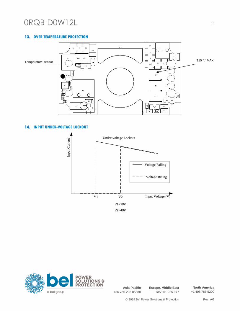
13. OVER TEMPERATURE PROTECTION
14. INPUT UNDER-VOLTAGE LOCKOUT
V1=38V
V2=40V
Input Voltage (V)
Inp
ut
Cu
rren
t
Voltage Falling
Voltage Rising
V1 V2
Under-voltage Lockout
115 ℃ MAX Temperature sensor

12
0RQB-D0W12L
belfuse.com/power-solutions
15. SAFETY & EMC
Safety:
1. Compliance to UL/CSA 60950-1
2. Compliance to IEC/EN 60950-1
EMC
Setup:
T1A CX1 RY11 RY12 CY11 CY12
330uF AL -
T2A CX2 RY21 RY22 CY21 CY22
1mH 1uF 0R 0R 2.2uF 2.2uF
CX3 RY31 RY32 CY31 CY32
1uF -
CX4 RY41 RY42 CY41 CY42
220uF AL -
0RQB-D0W12L 13
Asia-Pacific
+86 755 298 85888 Europe, Middle East
+353 61 225 977 North America
+1 408 785 5200
© 2019 Bel Power Solutions & Protection Rev. AG
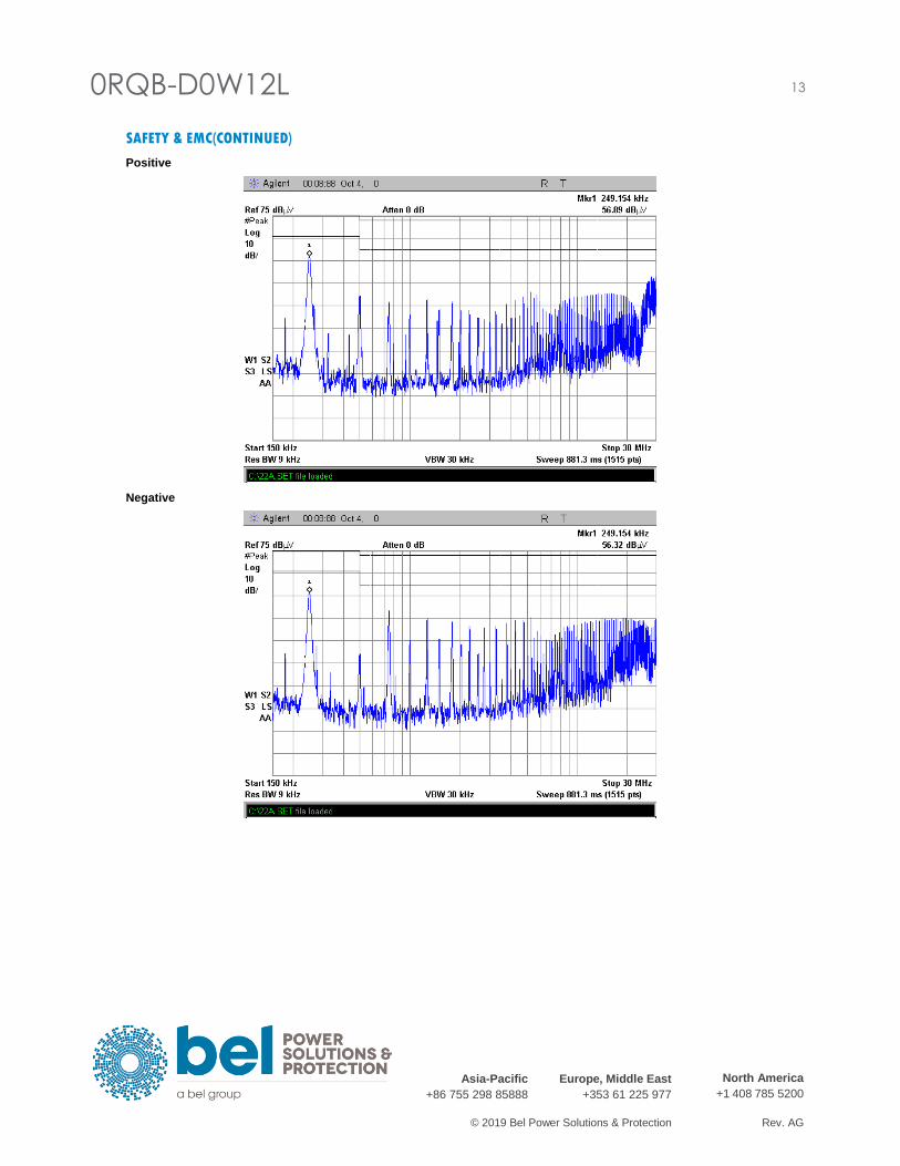
SAFETY & EMC(CONTINUED)
Positive
Negative
14
0RQB-D0W12L
belfuse.com/power-solutions
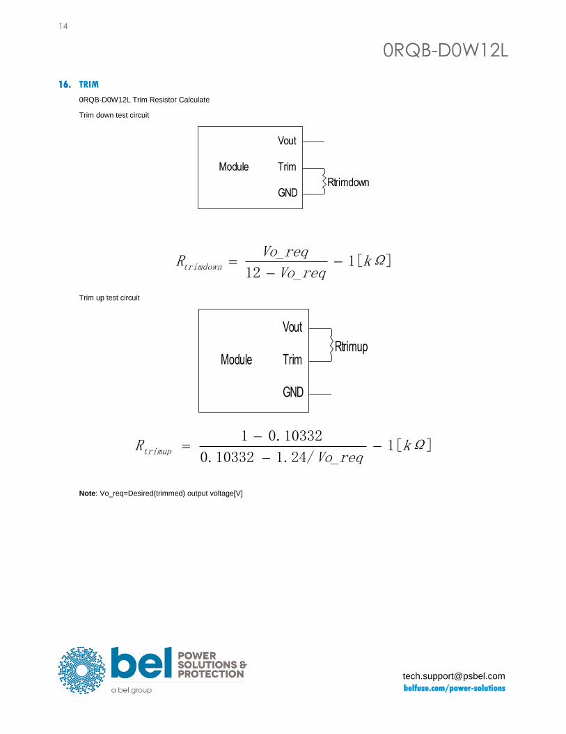
16. TRIM
0RQB-D0W12L Trim Resistor Calculate
Trim down test circuit
]1[21
kΩVo_req
Vo_reqRtrimdown −
−=
Trim up test circuit
Note: Vo_req=Desired(trimmed) output voltage[V]
Module
Vout
Trim
GNDRtrimdown
Module
Vout
Trim
GND
Rtrimup
]1[1.24/0.10332
0.103321kΩ
Vo_reqRtrimup −
−
−=
0RQB-D0W12L 15
Asia-Pacific
+86 755 298 85888 Europe, Middle East
+353 61 225 977 North America
+1 408 785 5200
© 2019 Bel Power Solutions & Protection Rev. AG
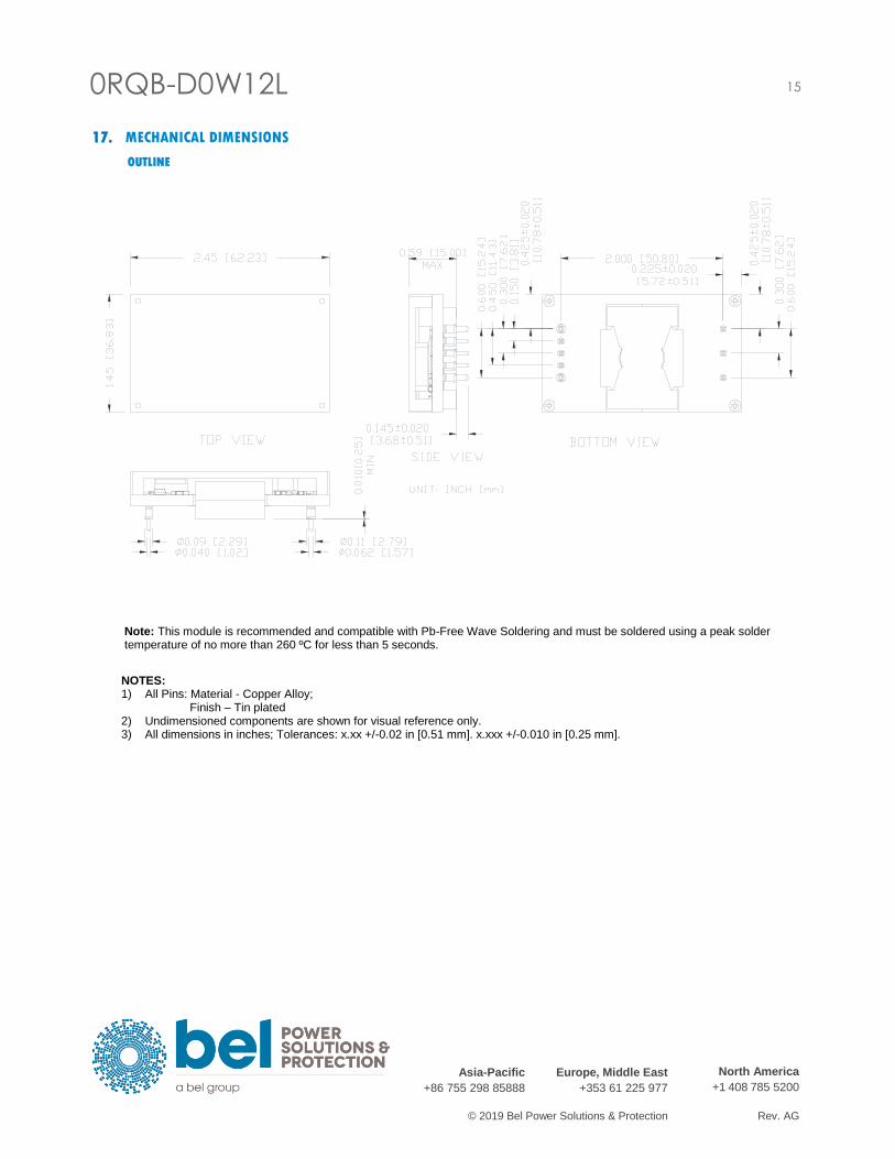
17. MECHANICAL DIMENSIONS
OUTLINE
Note: This module is recommended and compatible with Pb-Free Wave Soldering and must be soldered using a peak solder temperature of no more than 260 ºC for less than 5 seconds.
NOTES: 1) All Pins: Material - Copper Alloy; Finish – Tin plated 2) Undimensioned components are shown for visual reference only. 3) All dimensions in inches; Tolerances: x.xx +/-0.02 in [0.51 mm]. x.xxx +/-0.010 in [0.25 mm].
16
0RQB-D0W12L
belfuse.com/power-solutions
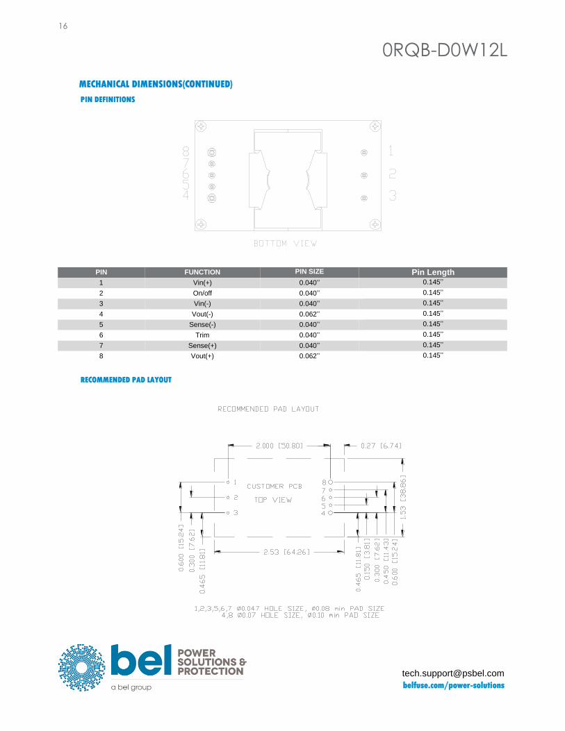
MECHANICAL DIMENSIONS(CONTINUED)
PIN DEFINITIONS
RECOMMENDED PAD LAYOUT
PIN FUNCTION PIN SIZE Pin Length
1 Vin(+) 0.040’’ 0.145’’
2 On/off 0.040’’ 0.145’’
3 Vin(-) 0.040’’ 0.145’’
4 Vout(-) 0.062’’ 0.145’’
5 Sense(-) 0.040’’ 0.145’’
6 Trim 0.040’’ 0.145’’
7 Sense(+) 0.040’’ 0.145’’
8 Vout(+) 0.062’’ 0.145’’

0RQB-D0W12L 17
Asia-Pacific
+86 755 298 85888 Europe, Middle East
+353 61 225 977 North America
+1 408 785 5200
© 2019 Bel Power Solutions & Protection Rev. AG
18. REVISION HISTORY
DATE REVISION CHANGES DETAIL APPROVAL
2016-09-09 AA First release Z Tang
2017-04-13 AB Update Input Voltage J Yan
2017-06-07 AC Update Input Specs J Yan
2017-08-04 AD Update Efficiency Data S Wang
2017-08-22 AE Update Operating Input Voltage S Wang
2018-03-07 AF Update MTBF S Wang
2019-04-25 AG Update Input Specifications and Mechanical Dimensions S Wang
For more information on these products consult: [email protected]
NUCLEAR AND MEDICAL APPLICATIONS - Products are not designed or intended for use as critical components in life support systems, equipment used in hazardous environments, or nuclear control systems. TECHNICAL REVISIONS - The appearance of products, including safety agency certifications pictured on labels, may change depending on the date manufactured. Specifications are subject to change without notice.