thank you for your order! - finescale.com/media/files/pdf/circulation/fspdf026.pdf · 2015. 10....
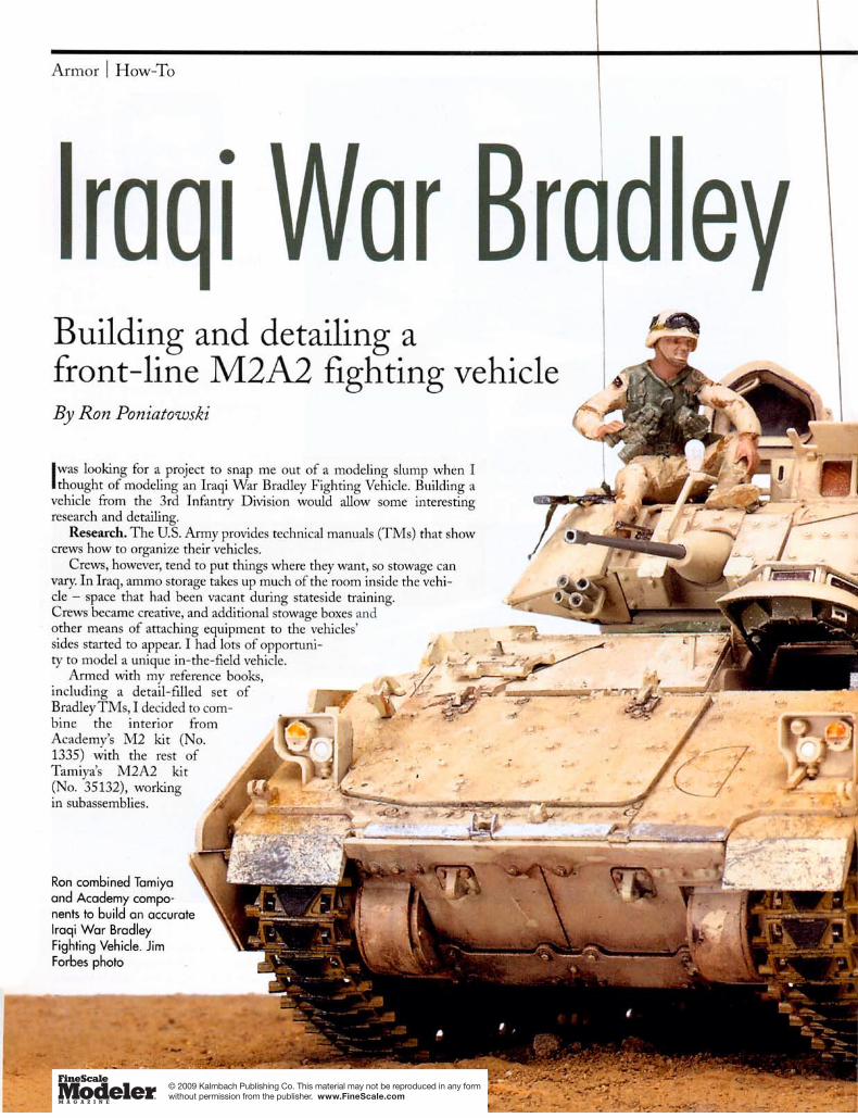
TRANSCRIPT

Thank you for your order! Enjoy your FSM Direct–Downloadable Article.
Please remember that this copyrighted material is for your use only. It’s unlawful to share or distribute this file to others in any way including e-mailing it, posting it online, or sharing paper copies with others.
Sincerely,
The staff of FineScale Modeler
Troubleshooting Guide:
Please note: Packages are color intensive. To save color ink in your printer, change your printer setting to grayscale.
SavinG packaGeSave the package when you download the PDF. Click on the computer disk icon in Adobe Acrobat, or go to File, Save.
My prinTer won’T prinT The TexT correcTlyClose all other programs/applications and print directly out of the Acrobat Reader program, not your Web browser. Printing problems are caused by not enough free system memory.
paGeS are noT prinTinG full SizeSet your printer to print 100% and make sure “print to fit” is not checked under printer setup or printer options.
If you have suggestions on how we can improve this product or have topics you’d like to see in future FSM Direct packages, please contact us at [email protected]
FSPDF026
8
www.FineScaleModeler.comP R O D U C T S

Model modern American armor
FSPDF026
FSM DirectDOWNLOADABLE ARTICLES
Like any detail-minded armor modeler, I enjoy examiningminutiae – counting bolts, looking at close-up photos, andfinding ways to improve a kit by adding a few easily mod-
eled features to make a vehicle more accurate or timely. It’s evenmore enjoyable when you start with a good kit right out of thebox, because you can go straight to the fun stuff – details!
One such build is Tamiya’s M2A2 Bradley (No. 35152), one ofa new generation of high-quality armor models. It’s a great kit –but I found ways to improve it with parts of Tamiya’s earlierBradley M2 (No. 35132), as well as bits and pieces from after-market detail sets, spare parts, and a few little scratchbuilt items.
Start with the hull. I veered off the kit instructions at aboutstep 4, leaving off the tow cable and other stowed items to paintthem separately. I also saved the armored side skirts for later, aftereverything else was painted but before weathering the vehicle;building and painting (especially the running gear) is much easi-er that way.
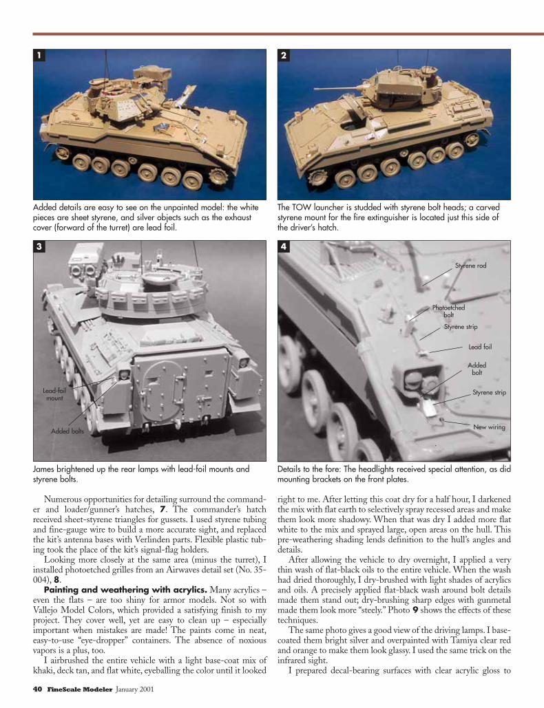
Photo 1 shows the scratchbuilt elevation arm I made for thedriver’s hatch, as well as a lead-foil exhaust cover detailed withstyrene bolt heads. Photo 2 shows more added bolts as well as acarved-styrene fire extinguisher mount.
The rear lamps received lead-foil mounts and hex nuts toreplicate bolt attachments, 3. I made these and other hex nutsfrom sheet styrene, using a Historex punch-and-die set.
What’s up front – and at the top. The driving lamps herewere detailed with styrene bolts and lead foil for conduit bracketsand electrical contacts, 4. Additional mounting brackets, madefrom styrene rod and strip and detailed with Nimix photoetchedbolts, also went up front.
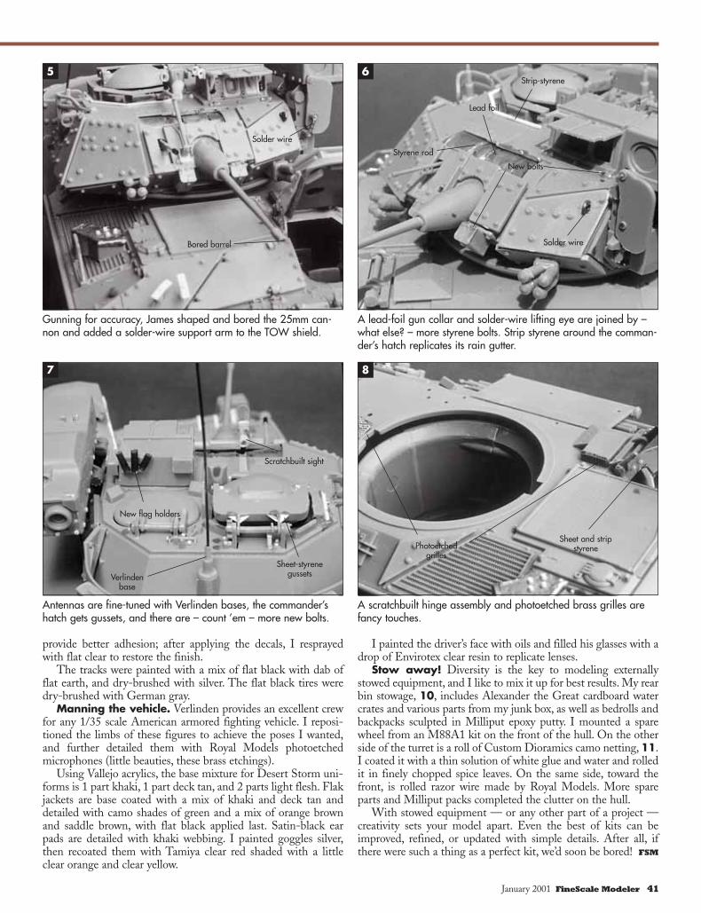
I made a support-arm for the TOW missile launcher shieldwith fine solder flattened on the ends, 5. Later, I bored out thefront of the launcher and armed it with the tips of two warheads(actually reshaped Italeri Nebelwerfer rockets).
I also reshaped the end of the main gun, sanding it round andboring it out with a mini-drill at low speed to avoid melting theplastic. Lead foil worked well as a gun collar, 6. The smokegrenade boxes each received three Grandt Line bolt heads. Stripstyrene depicts a rain gutter around the commander’s hatch. Alifting eye on the mantlet is made from flattened solder.
Decorate a Gulf War herowith accurate detailsBy James Welch Photos by the author
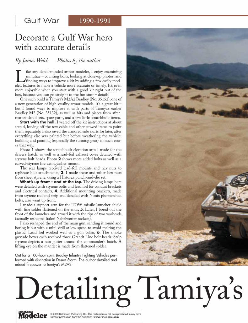
Out for a 100-hour spin: Bradley Infantry Fighting Vehicles per-formed with distinction in Desert Storm. The author detailed andadded firepower to Tamiya’s M2A2.
Detailing Tamiya’s
Gulf War 1990-1991
© 2009 Kalmbach Publishing Co. This material may not be reproduced in any form without permission from the publisher. www.FineScale.com

1/35 Scale
M2A2 BradleyJanuary 2001 FineScale Modeler 39
Numerous opportunities for detailing surround the command-er and loader/gunner’s hatches, 7. The commander’s hatchreceived sheet-styrene triangles for gussets. I used styrene tubingand fine-gauge wire to build a more accurate sight, and replacedthe kit’s antenna bases with Verlinden parts. Flexible plastic tub-ing took the place of the kit’s signal-flag holders.
Looking more closely at the same area (minus the turret), Iinstalled photoetched grilles from an Airwaves detail set (No. 35-004), 8.
Painting and weathering with acrylics. Many acrylics –even the flats – are too shiny for armor models. Not so withVallejo Model Colors, which provided a satisfying finish to myproject. They cover well, yet are easy to clean up – especiallyimportant when mistakes are made! The paints come in neat,easy-to-use “eye-dropper” containers. The absence of noxiousvapors is a plus, too.
I airbrushed the entire vehicle with a light base-coat mix ofkhaki, deck tan, and flat white, eyeballing the color until it looked
right to me. After letting this coat dry for a half hour, I darkenedthe mix with flat earth to selectively spray recessed areas and makethem look more shadowy. When that was dry I added more flatwhite to the mix and sprayed large, open areas on the hull. Thispre-weathering shading lends definition to the hull’s angles anddetails.
After allowing the vehicle to dry overnight, I applied a verythin wash of flat-black oils to the entire vehicle. When the washhad dried thoroughly, I dry-brushed with light shades of acrylicsand oils. A precisely applied flat-black wash around bolt detailsmade them stand out; dry-brushing sharp edges with gunmetalmade them look more “steely.” Photo 9 shows the effects of thesetechniques.
The same photo gives a good view of the driving lamps. I base-coated them bright silver and overpainted with Tamiya clear redand orange to make them look glassy. I used the same trick on theinfrared sight.
I prepared decal-bearing surfaces with clear acrylic gloss to
Added details are easy to see on the unpainted model: the whitepieces are sheet styrene, and silver objects such as the exhaustcover (forward of the turret) are lead foil.
James brightened up the rear lamps with lead-foil mounts andstyrene bolts.
The TOW launcher is studded with styrene bolt heads; a carvedstyrene mount for the fire extinguisher is located just this side ofthe driver’s hatch.
Details to the fore: The headlights received special attention, as didmounting brackets on the front plates.
1 2
4
Added bolt
New wiring
Styrene strip
Lead foil
Styrene strip
Photoetchedbolt
Styrene rod
40 FineScale Modeler January 2001
Added bolts
Lead-foilmount
3
provide better adhesion; after applying the decals, I resprayedwith flat clear to restore the finish.
The tracks were painted with a mix of flat black with dab offlat earth, and dry-brushed with silver. The flat black tires weredry-brushed with German gray.
Manning the vehicle. Verlinden provides an excellent crewfor any 1/35 scale American armored fighting vehicle. I reposi-tioned the limbs of these figures to achieve the poses I wanted,and further detailed them with Royal Models photoetchedmicrophones (little beauties, these brass etchings).
Using Vallejo acrylics, the base mixture for Desert Storm uni-forms is 1 part khaki, 1 part deck tan, and 2 parts light flesh. Flakjackets are base coated with a mix of khaki and deck tan anddetailed with camo shades of green and a mix of orange brownand saddle brown, with flat black applied last. Satin-black earpads are detailed with khaki webbing. I painted goggles silver,then recoated them with Tamiya clear red shaded with a littleclear orange and clear yellow.
I painted the driver’s face with oils and filled his glasses with adrop of Envirotex clear resin to replicate lenses.
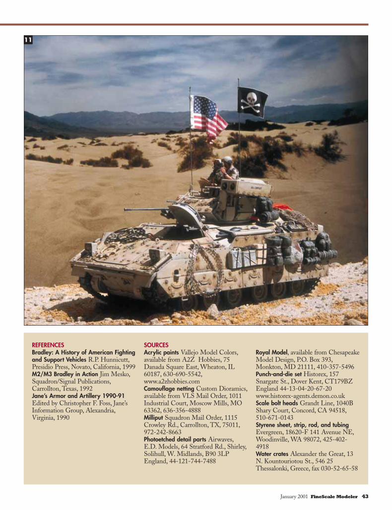
Stow away! Diversity is the key to modeling externallystowed equipment, and I like to mix it up for best results. My rearbin stowage, 10, includes Alexander the Great cardboard watercrates and various parts from my junk box, as well as bedrolls andbackpacks sculpted in Milliput epoxy putty. I mounted a sparewheel from an M88A1 kit on the front of the hull. On the otherside of the turret is a roll of Custom Dioramics camo netting, 11.I coated it with a thin solution of white glue and water and rolledit in finely chopped spice leaves. On the same side, toward thefront, is rolled razor wire made by Royal Models. More spareparts and Milliput packs completed the clutter on the hull.
With stowed equipment — or any other part of a project —creativity sets your model apart. Even the best of kits can beimproved, refined, or updated with simple details. After all, ifthere were such a thing as a perfect kit, we’d soon be bored! FSM
Gunning for accuracy, James shaped and bored the 25mm can-non and added a solder-wire support arm to the TOW shield.
A lead-foil gun collar and solder-wire lifting eye are joined by –what else? – more styrene bolts. Strip styrene around the comman-der’s hatch replicates its rain gutter.
Antennas are fine-tuned with Verlinden bases, the commander’shatch gets gussets, and there are – count ’em – more new bolts.
A scratchbuilt hinge assembly and photoetched brass grilles arefancy touches.
5 6
7 8
Bored barrel
Solder wire
Styrene rod
Solder wire
New bolts
Lead foil
Strip-styrene
Verlindenbase
New flag holders
Sheet-styrenegussets
Scratchbuilt sight
Sheet and stripstyrenePhotoetched
grilles
January 2001 FineScale Modeler 41
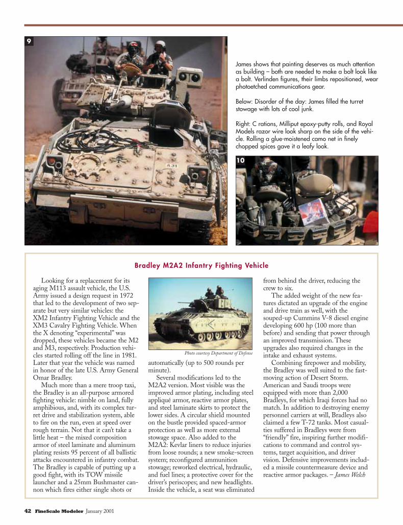
James shows that painting deserves as much attentionas building – both are needed to make a bolt look likea bolt. Verlinden figures, their limbs repositioned, wearphotoetched communications gear.
Right: C rations, Milliput epoxy-putty rolls, and RoyalModels razor wire look sharp on the side of the vehi-cle. Rolling a glue-moistened camo net in finelychopped spices gave it a leafy look.
Below: Disorder of the day: James filled the turretstowage with lots of cool junk.
9
10
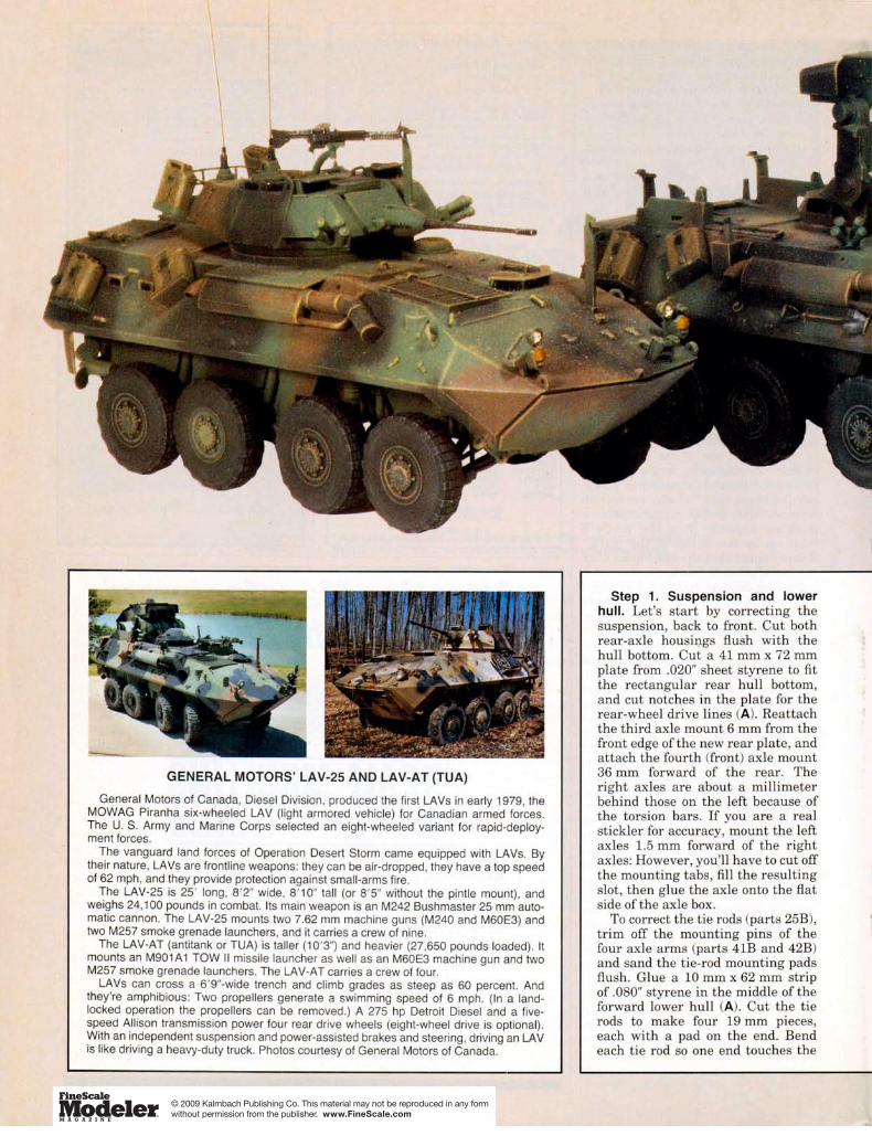
Looking for a replacement for itsaging M113 assault vehicle, the U.S.Army issued a design request in 1972that led to the development of two sep-arate but very similar vehicles: theXM2 Infantry Fighting Vehicle and theXM3 Cavalry Fighting Vehicle. Whenthe X denoting “experimental” wasdropped, these vehicles became the M2and M3, respectively. Production vehi-cles started rolling off the line in 1981.Later that year the vehicle was namedin honor of the late U.S. Army GeneralOmar Bradley.
Much more than a mere troop taxi,the Bradley is an all-purpose armoredfighting vehicle: nimble on land, fullyamphibious, and, with its complex tur-ret drive and stabilization system, ableto fire on the run, even at speed overrough terrain. Not that it can’t take alittle heat – the mixed compositionarmor of steel laminate and aluminumplating resists 95 percent of all ballisticattacks encountered in infantry combat.The Bradley is capable of putting up agood fight, with its TOW missilelauncher and a 25mm Bushmaster can-non which fires either single shots or
automatically (up to 500 rounds perminute).
Several modifications led to theM2A2 version. Most visible was theimproved armor plating, including steelappliqué armor, reactive armor plates,and steel laminate skirts to protect thelower sides. A circular shield mountedon the bustle provided spaced-armorprotection as well as more externalstowage space. Also added to theM2A2: Kevlar liners to reduce injuriesfrom loose rounds; a new smoke-screensystem; reconfigured ammunitionstowage; reworked electrical, hydraulic,and fuel lines; a protective cover for thedriver’s periscopes; and new headlights.Inside the vehicle, a seat was eliminated
from behind the driver, reducing thecrew to six.
The added weight of the new fea-tures dictated an upgrade of the engineand drive train as well, with thesouped-up Cummins V-8 diesel enginedeveloping 600 hp (100 more thanbefore) and sending that power throughan improved transmission. Theseupgrades also required changes in theintake and exhaust systems.
Combining firepower and mobility,the Bradley was well suited to the fast-moving action of Desert Storm.American and Saudi troops wereequipped with more than 2,000Bradleys, for which Iraqi forces had nomatch. In addition to destroying enemypersonnel carriers at will, Bradleys alsoclaimed a few T-72 tanks. Most casual-ties suffered in Bradleys were from“friendly” fire, inspiring further modifi-cations to command and control sys-tems, target acquisition, and drivervision. Defensive improvements includ-ed a missile countermeasure device andreactive armor packages. – James Welch
Bradley M2A2 Infantry Fighting Vehicle
Photo courtesy Department of Defense
42 FineScale Modeler January 2001
11
REFERENCESBradley: A History of American Fightingand Support Vehicles R.P. Hunnicutt,Presidio Press, Novato, California, 1999M2/M3 Bradley in Action Jim Mesko,Squadron/Signal Publications,Carrollton, Texas, 1992Jane’s Armor and Artillery 1990-91Edited by Christopher F. Foss, Jane’sInformation Group, Alexandria,Virginia, 1990
SOURCESAcrylic paints Vallejo Model Colors,available from A2Z Hobbies, 75Danada Square East, Wheaton, IL60187, 630-690-5542,www.a2zhobbies.comCamouflage netting Custom Dioramics,available from VLS Mail Order, 1011Industrial Court, Moscow Mills, MO63362, 636-356-4888Milliput Squadron Mail Order, 1115Crowley Rd., Carrollton, TX, 75011,972-242-8663Photoetched detail parts Airwaves,E.D. Models, 64 Stratford Rd., Shirley,Solihull, W. Midlands, B90 3LPEngland, 44-121-744-7488
Royal Model, available from ChesapeakeModel Design, P.O. Box 393,Monkton, MD 21111, 410-357-5496Punch-and-die set Historex, 157Snargate St., Dover Kent, CT179BZEngland 44-13-04-20-67-20 www.historex-agents.demon.co.ukScale bolt heads Grandt Line, 1040BShary Court, Concord, CA 94518,510-671-0143Styrene sheet, strip, rod, and tubingEvergreen, 18620-F 141 Avenue NE,Woodinville, WA 98072, 425-402-4918Water crates Alexander the Great, 13N. Kountouriotou St., 546 25Thessalonki, Greece, fax 030-52-65-58
January 2001 FineScale Modeler 43
© 2009 Kalmbach Publishing Co. This material may not be reproduced in any form without permission from the publisher. www.FineScale.com


W hen I bought the 1/35 scale Shanghai Dragon M1A2 Abrams kit, I found that most of the kit’s
details were accurate. But as nice as this kit is straightfrom the box, with just a bit of added effort, you can make amuch better model.
The hull. Because I planned to mount the Abrams on a dis-play pedestal, my first step was to drill a 5⁄32" hole in the centerof the lower hull. I epoxied a nut to the inside of the hull overthe hole, then ran a securing bolt through the bottom of the dis-play board into the model.
The front four feet or so of the real Abrams fenders are
hinged to swing up. There are wire torsion springs to hold themin the closed position, which the kit omits. I made the springsfrom .020" brass wire, and held them in place with small loopsof the same wire stock. The forward ends of the torsion springsare cradled in pieces of .004" shim brass. The brass was formed
Armor | How-To
AbramsDetailing Shanghai Dragon’s M1A2
Abrams main battle tank
Accurate
The U.S. Army asked General Dynamics Land Systems to make afew upgrades to the Abrams main battle tank – resulting in theM1A2. Author Greg Kolasa of Wantage, New Jersey, made surehis 1/35 scale model accurately reflected these changes. JimForbes photo.
By Greg Kolasa
Jim Forbes photo
52 FineScale Modeler July 2001© 2009 Kalmbach Publishing Co. This material may not be reproduced in any form without permission from the publisher. www.FineScale.com

over a piece of the wire, creating a “J” shape, 1.While I had the wire out, I replaced the upper-hull grab han-
dle with one made from wire. The grab handle nestled behindthe side-skirt latch mechanism would be nearly impossible tograb from ground level, so I changed its location. The outlet forthe hull bilge pump nestles under the turret. While the kit hasa nicely molded deep opening, the pipe on the actual Abrams iscovered with a rubber boot, its end “flattened” to keep water anddebris out of the pipe. I crimped the end of a 1⁄16" aluminumtube, then super-glued it in place. After the super glue cured, Idrilled a 1⁄16" hole through the fairing and into the hull. After theboot was attached, I checked the fit of the turret through fullrotation, 2.
Next I assembled of the rear face of the hull, leaving off theoptional box-like structure on the rear panel. The instructionsaren’t clear as to the orientation of the taillight guards. A look atmy references revealed that these openings are toward the insidetop when viewed from the rear, 3.
The two tabs flanking the lower tow hook on the rear faceshould have holes drilled in them, as they’re for mounting towlugs. On the upper surface of the rear face there are two liftinglugs (again, molded as tabs without holes in them). I replacedthem with brass stock, but relocated the one on the right to thecenter of the middle grille. With all the details added, I attachedthe rear face to the lower hull, where I had to fill and sand a largeseam.
This was where my assembly diverged from the planssequence; the kit order would have made painting difficult. Step3 instructed me to attach the side armor skirts to the upper hull;I saved this for later on, after the vehicle was painted.Meanwhile I joined the side skirts with several pieces of sheetstyrene on the backside for strength, 4. I made sure the glue setthe assembly straight by laying it flat, and before they totally setup, I checked that they aligned properly along the hull. Whilethe skirts dried, I went to the upper hull.
Directly aft of part A6 there should be a scale 3" x 5" well inwhich the engine compartment fire extinguisher system “T”handle sits. The side armor skirt was dry-fitted to the hull toserve as a guide for the well since it is directly aft of the hinge.I drilled a round hole, then filed it square. A piece of sheetstyrene was cemented to the backside, closing off the well, andthe tiny “T” handle was made from two pieces of strip styrene.The area on the hull side (A1) beneath the opening of A6 wasdrilled out to provide the look of a deeper opening when A6 wascemented in place over the holes.
The lower side skirt hinges are mounted to tubes (approxi-mately 4" in diameter) which project out from the hull betweenthe upper and lower tracks. I duplicated these tubes on the kitbecause they helped stiffen the side skirt mounting. Four 1⁄8"holes were drilled through the hull to correspond with theapproximate location of the skirt hinges. A word of caution:measure the location of the holes on one side of the hull, thenmeasure the location on the other side from a fixed point. Don’tdrill holes on the second side based on the spacing between theroad wheel axles – the road wheels aren’t in the same location onboth sides.
Once the holes were drilled, I dry-fitted the skirt assemblyon one side, and passed 1⁄8" styrene tubes through the holes untilthey just contacted the side skirts, 5. After cementing them inplace, I used a pair of dividers to measure and trim the tubes onthe other side to mount the skirts there. I also drilled out the
1/35 Scale
Thin brass wire is used to make the fender torsion springs. Theend nestles into a “J” bracket formed from brass sheet.
Greg used thin aluminum tubing (flattened at one end) for thebilge-pump outlet. Before gluing, ensure that it stays below theturret bottom by test-fitting the turret to the hull.
The two small lifting lugs were replaced with fine wire, and thepower cable running to the right rear taillight was added. Notethe position of the notches on the light shrouds.
1
2
3
July 2001 www.finescale.com 53
lightening holes in the track return rollers only to realize they’dbe virtually invisible under the armor skirts.
It’s important that all of the road wheels touch the groundsimultaneously, or the tracks won’t fit right. I opened up theholes in the wheels slightly, so they fit a bit loosely on the axles.When it came time to mount the road wheels, I cemented themto the axles with slow-setting cement, then placed the hull on alevel surface and filled it with lead shot. The added weightensured that all fourteen wheels touched the ground at the sametime. The upper and lower hulls were then cemented together,and the seam on the front glacis was filled. Next I moved top-side to the turret, an area which required a bit more effort.
Onwards and upwards. The driver’s hatch needed a bitof work. The areas where the driver looks through are moldedas open areas, and this is correct – however, the periscopic visionblocks are not provided. These features, on the driver’s hatchand up around the commander’s weapons station as well, allowthe crew to look through an opening indirectly through a seriesof prisms. To simulate the prisms, I carved three pieces of .030"styrene to fit loosely into the openings in the hatch, 6. Thereshould be air space around the blocks as they fit into the hatchrecesses. They’re small, so it’s easier to paint them outside theninstall them, which is best done after the tank is painted. Later,after painting, I also simulated two windshield wipers on thecenter pane with 1⁄64" black drafting tape.
Continuing upwards, I started the turret assembly. Theupper and lower turret parts needed filling and sanding. Becauseof the sharp angles of the Abrams turret, the kit parts weremolded so that the upper part fits over the base sections. Thetrick was not allowing the base to “sink” too far into the upperpart as the cement was setting, since this would cause the sidesof the turret to scrape the hull as the completed turret was tra-versed.
The side stowage boxes didn’t fit well to the turret. I outlinedthe location of the boxes on the turret side with a pencil, thenremoved the locating tabs and fit the boxes flush to the turretsides. I chose to replace the side basket rods with .031" brasswire, 7. The rearmost side brackets for the basket rods, wheninstalled as per the kit locating pins, were too close to the turretsides. As a result, the rods which should have intersected themwould pass right over the top. The cure was to make two small.070" thick styrene blocks which would space out the bracketsfrom the turret sides.
After the side baskets were dry, the vent stack was cut from1⁄8" plastic rod and cemented into place as shown, 8. A slightlylarger diameter “cap” was carved from scrap plastic and placed tocover the vent assembly. Notice that when it’s done, it should beapproximately the same height as the top of the stowage boxes.
The ammunition compartment bustle blowoff doors of thereal M1A2 do have the six flat discs on top, but they should beflat, without the relief details of the kit-supplied discs. Beforeinstalling them, I passed them over some sandpaper a few timesto reduce the raised detail. The doors fit within a recessedgroove in the turret roof, and the right door seat was molded“filled in,” and as a result the door didn’t fit properly into its seat.A bit of grinding with a motor tool opened up this channel, andthe door fit properly. The turret rear panel also required quite abit of sanding to get it to fit right.
The 120mm gun mantlet is nicely molded, but I had a prob-lem with the rear upper portion of the assembly. On the actualAbrams, this panel is hinged to allow it to move up or down asthe gun is elevated or lowered. This hinged panel fills the “gap”
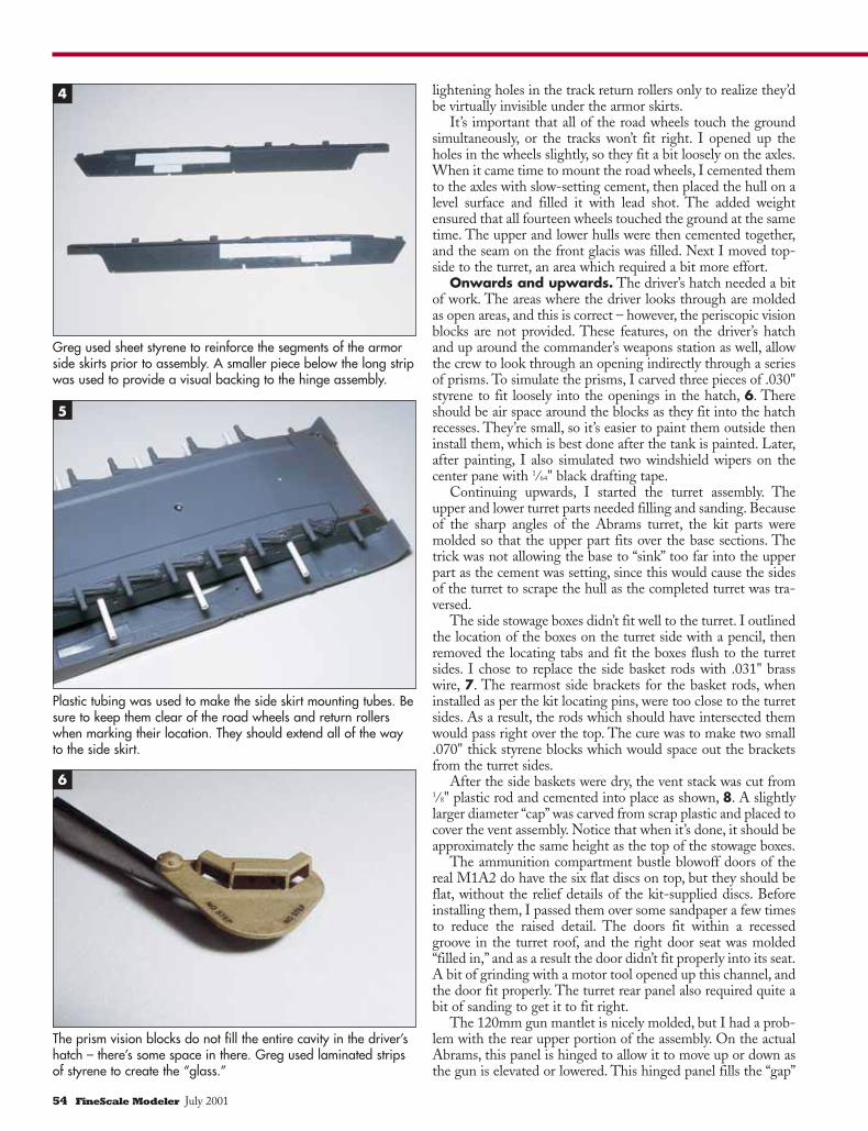
Plastic tubing was used to make the side skirt mounting tubes. Besure to keep them clear of the road wheels and return rollerswhen marking their location. They should extend all of the wayto the side skirt.
The prism vision blocks do not fill the entire cavity in the driver’shatch – there’s some space in there. Greg used laminated stripsof styrene to create the “glass.”
5
6
Greg used sheet styrene to reinforce the segments of the armorside skirts prior to assembly. A smaller piece below the long stripwas used to provide a visual backing to the hinge assembly.
4
54 FineScale Modeler July 2001
as the mantlet moves. The kit plans said to cement this part tothe forward mantlet top, but doing so would prevent the gunfrom elevating. A means of hinging the panel on the model wasneeded. I fit the two parts together and taped them into posi-tion, then smeared the back with silicone bathtub caulk. Thecaulk remained flexible after drying, allowing the filler panel tomove a bit.
Another problem was discovered – with the gun at the zeroelevation, the top of the mantlet should be flush with the top ofthe turret. On the kit, the mantlet is mounted 1⁄16" too high. Tocorrect the fit of the mantlet, I used a motor tool to thin thewalls of the receptacle on top. They were thick enough to takeit, and thinning them allowed me to mount the mantlet slight-ly lower on the trunion for a more realistic fit, 9.
Basket weaving. The very first step in the construction ofthe turret stowage basket was to cement the upper and lowerhalves of the main frame together. That done, the circular rodsmolded into the basket parts were cut out and replaced with the.031" brass wire. All the other places where wire was used toreplace the kit rods required only cutting and bending the wireto shape.
The bottom of the kit basket is formed with only two rods,but the Abrams has a diamond-patterned metal screen as thefloor of the basket, so I cut brass screen to fit. Once the finaltrimming of the screen was completed, it was secured with a fewtiny drops of super glue, 10.
Target acquired. The gunner’s thermal imager and laserrange finder were assembled next. While the instructions wouldhave you paint the inside of the thermal imager white, it shouldactually be tan, the color of the overall tank. Since the unit sim-ply sits atop the turret, I chose to paint it along with the turretand hull. I made a .020" brass wire grab handle and added it tothe loader’s hatch.
Next I tackled the ICWS (Improved Commander’sWeapons Station) and CITV (Commander’s IndependentThermal Viewer). The Abrams tank on the box sides show theCITV in the correct shape, but the item supplied in the kit is abit off. The real CITV, when viewed from directly above, lookslike a keyhole: circular, with a small rectangular protrusion atone edge. The kit shows it as rectangular with a rounded edge.I decided it would look much better if the front of the kit-supplied CITV were attached to a circular cylinder, so a visit tothe scrap box yielded me a drop tank half, type and scale unde-termined.
The drop tank had a fairly long straight cylindrical section,and when the halves were glued together, they appeared to bejust about the right diameter (.361"). I cut out a section just a bitlonger than 1⁄4", and trimmed the front half of the kit’s CITVfrom the remainder. It would be butt-welded to the cylinder, soa handful of passes over 400-grit sandpaper (wrapped aroundthe rest of the drop tank) provided the round edge to mate withthe new CITV body. After joining the two flush with the top ofthe kit-supplied CITV, I cut a small disc from sheet styrene andglued it into the open end, forming the top of the “new” CITV.The roof was then filled and sanded smooth. The new CITVwas passed repeatedly over 600-grit paper until the bottom ofthe cylinder was the same height as the front. The real CITVhas a welded-on panel on the rear side (opposite the view port);I simulated this with a piece of sheet plastic. It was formed overa paintbrush handle (to give it the proper curve) and was then“welded” in place with cement, 11.
The ICWS was next. The “real” unit features an octagonal
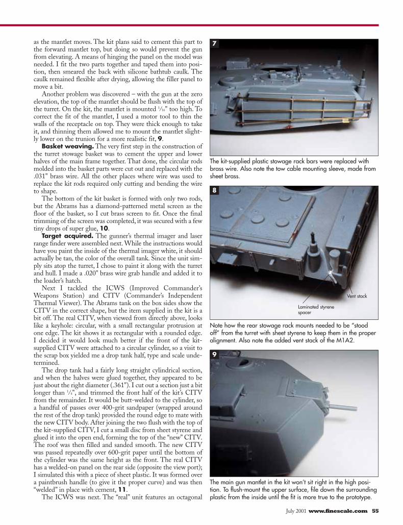
The kit-supplied plastic stowage rack bars were replaced withbrass wire. Also note the tow cable mounting sleeve, made fromsheet brass.
Note how the rear stowage rack mounts needed to be “stoodoff” from the turret with sheet styrene to keep them in the properalignment. Also note the added vent stack of the M1A2.
The main gun mantlet in the kit won’t sit right in the high posi-tion. To flush-mount the upper surface, file down the surroundingplastic from the inside until the fit is more true to the prototype.
7
8
9
Laminated styrenespacer
Vent stack
July 2001 www.finescale.com 55
ring of periscopic vision blocks surrounding the hatch. Forwhatever reason, the kit replaced the forward-facing visionblock with something that looks like the flip-up screen of a lap-top PC. To replace it I laminated a pile of sheet plastic to forma stack of the proper thickness, and trimmed this stack to theproper size and shape to fill in the gap on the vision block ring.Once a good fit was achieved, it was cemented in place, and a.010" piece of sheet plastic was cut to simulate the raised visionglass. A few passes over 600-grit sandpaper ensured that the topof the new piece was the same height as the remainder of thevision block ring. Finally, I drilled four tiny holes into the newvision block to match holes that appear in the remaining sevensegments of the vision block ring – a No. 75 drill bit was aboutthe right size.
I added tow cables along the bottom edge of the turret. Thekit-provided tow cables are okay for this model, but on the realAbrams the rear loops slide into steel “sleeves” welded to theturret sides. The kit’s sleeves are molded into the cable lugs, justshowing up as blobs of plastic on the cable loops. I cleaned upthe loops and cut new mounting sleeves from .008" brass sheetstock and formed them over the ends of the cable.
This kit was manufactured without the twin whip antennasthat are usually at the rear of the turret. The real antennas arefiberglass and have a taper to them, along with a small teardrop-shaped ball at the tip. I couldn’t figure out how to replicate thiseffectively, so I decided to leave the antennas off. What usuallydoes show up are the spring antenna bases, and the kit doesn’tprovide them, either. To make them, I wrapped very fine wirearound a piece of thin music wire,12, then compressed the coilsso they sat one atop the next, making a “spring” over the wirecore. These two springs were super glued to the top of theantenna base. The springs are black, and they have the tiny redshipping caps atop them (to keep water out of the connectors).
Finishing. I decided to show the Abrams in the desertscheme, overall U.S. Army/Marines Gulf Armor Sand. TheTestors Model Master line has this color already mixed underthis name. I decided to depict a clean M1A2 just as it left thetank plant. The roadwheels and main gun were painted with afew drops of white added to show just a tad of a color mismatch.The various intakes and grilles were picked out with a darkerwash to give the illusion of depth. DML did some pretty nicedetail molding on the rear deck area, and the wash highlightstheir efforts. The left rear grille was also given a dark wash toaccentuate the moldings. The center grille is the turbineexhaust, and on the real vehicle, it and the right grille are paint-ed black.
The molded-in mounting tabs on the backsides of the towcables didn’t match up with the mounting indentations, so Itrimmed them flush. Since the mounting indentations placedthe tow cables too high up the sides of the turret, I filled themand touched up the paint. The cables are 1⁄4" too long, and weretrimmed to fit (note that on the real Abrams, only half of therear tow hooks slide into the sleeves). Finally, a gentle curveneeds to be added to the tow cables where they follow the lowercontour of the turret. My reference photos of factory-freshM1A1s showed the cables painted the same tan color as the restof the tank, but the cables just looked unfinished in tan so Ipainted them a metallic-black color.
All the glass on the Abrams is periscopic, so when the visionblocks are viewed from ground level they take on a peculiarmetallic orange-purple color as the light passes through a seriesof mirrors. They actually change color (to slightly more orange),
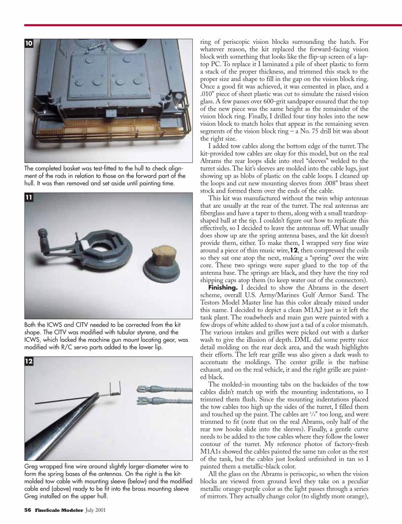
The completed basket was test-fitted to the hull to check align-ment of the rods in relation to those on the forward part of thehull. It was then removed and set aside until painting time.
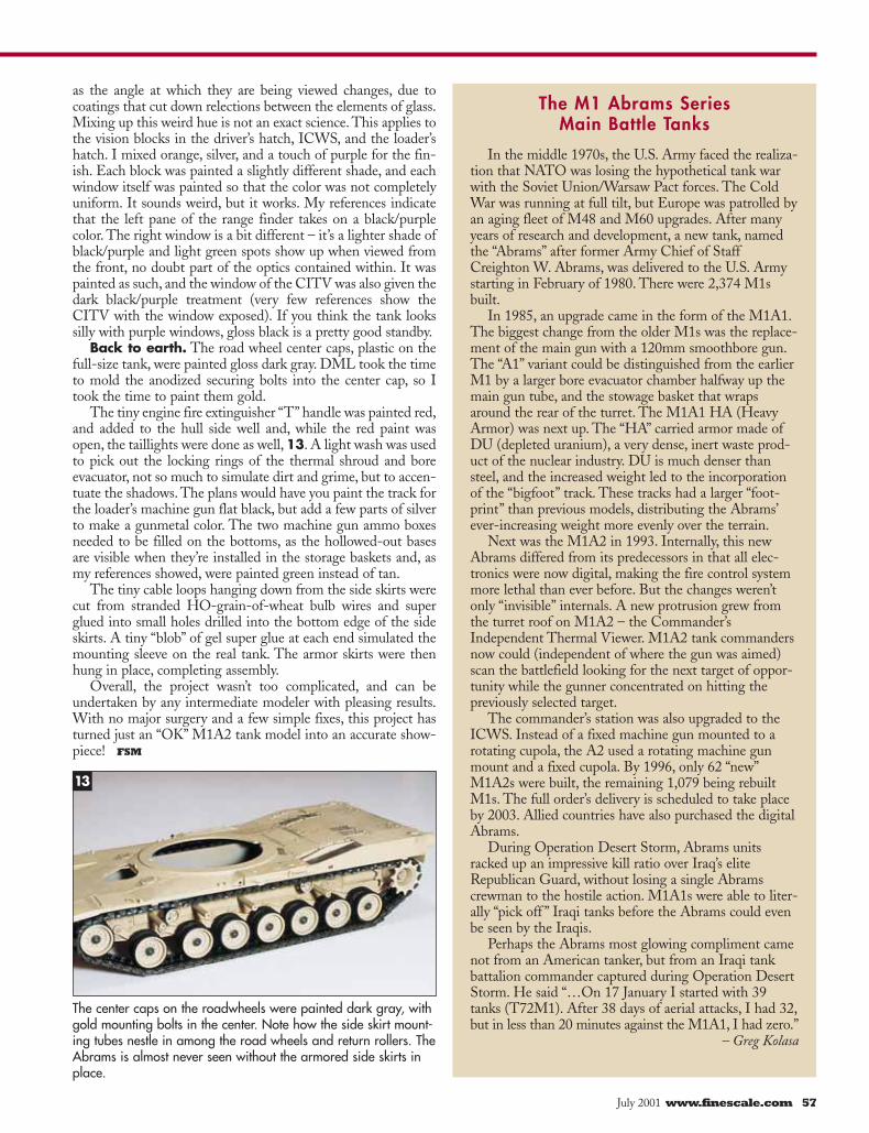
Both the ICWS and CITV needed to be corrected from the kitshape. The CITV was modified with tubular styrene, and theICWS, which lacked the machine gun mount locating gear, wasmodified with R/C servo parts added to the lower lip.
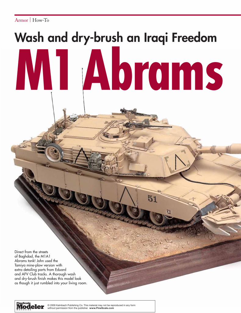
Greg wrapped fine wire around slightly larger-diameter wire toform the spring bases of the antennas. On the right is the kit-molded tow cable with mounting sleeve (below) and the modifiedcable end (above) ready to be fit into the brass mounting sleeveGreg installed on the upper hull.
10
11
12
56 FineScale Modeler July 2001
as the angle at which they are being viewed changes, due tocoatings that cut down relections between the elements of glass.Mixing up this weird hue is not an exact science. This applies tothe vision blocks in the driver’s hatch, ICWS, and the loader’shatch. I mixed orange, silver, and a touch of purple for the fin-ish. Each block was painted a slightly different shade, and eachwindow itself was painted so that the color was not completelyuniform. It sounds weird, but it works. My references indicatethat the left pane of the range finder takes on a black/purplecolor. The right window is a bit different – it’s a lighter shade ofblack/purple and light green spots show up when viewed fromthe front, no doubt part of the optics contained within. It waspainted as such, and the window of the CITV was also given thedark black/purple treatment (very few references show theCITV with the window exposed). If you think the tank lookssilly with purple windows, gloss black is a pretty good standby.
Back to earth. The road wheel center caps, plastic on thefull-size tank, were painted gloss dark gray. DML took the timeto mold the anodized securing bolts into the center cap, so Itook the time to paint them gold.
The tiny engine fire extinguisher “T” handle was painted red,and added to the hull side well and, while the red paint wasopen, the taillights were done as well, 13. A light wash was usedto pick out the locking rings of the thermal shroud and boreevacuator, not so much to simulate dirt and grime, but to accen-tuate the shadows. The plans would have you paint the track forthe loader’s machine gun flat black, but add a few parts of silverto make a gunmetal color. The two machine gun ammo boxesneeded to be filled on the bottoms, as the hollowed-out basesare visible when they’re installed in the storage baskets and, asmy references showed, were painted green instead of tan.
The tiny cable loops hanging down from the side skirts werecut from stranded HO-grain-of-wheat bulb wires and superglued into small holes drilled into the bottom edge of the sideskirts. A tiny “blob” of gel super glue at each end simulated themounting sleeve on the real tank. The armor skirts were thenhung in place, completing assembly.
Overall, the project wasn’t too complicated, and can beundertaken by any intermediate modeler with pleasing results.With no major surgery and a few simple fixes, this project hasturned just an “OK” M1A2 tank model into an accurate show-piece! FSM
In the middle 1970s, the U.S. Army faced the realiza-tion that NATO was losing the hypothetical tank warwith the Soviet Union/Warsaw Pact forces. The ColdWar was running at full tilt, but Europe was patrolled byan aging fleet of M48 and M60 upgrades. After manyyears of research and development, a new tank, namedthe “Abrams” after former Army Chief of StaffCreighton W. Abrams, was delivered to the U.S. Armystarting in February of 1980. There were 2,374 M1sbuilt.
In 1985, an upgrade came in the form of the M1A1.The biggest change from the older M1s was the replace-ment of the main gun with a 120mm smoothbore gun.The “A1” variant could be distinguished from the earlierM1 by a larger bore evacuator chamber halfway up themain gun tube, and the stowage basket that wrapsaround the rear of the turret. The M1A1 HA (HeavyArmor) was next up. The “HA” carried armor made ofDU (depleted uranium), a very dense, inert waste prod-uct of the nuclear industry. DU is much denser thansteel, and the increased weight led to the incorporationof the “bigfoot” track. These tracks had a larger “foot-print” than previous models, distributing the Abrams’ever-increasing weight more evenly over the terrain.
Next was the M1A2 in 1993. Internally, this newAbrams differed from its predecessors in that all elec-tronics were now digital, making the fire control systemmore lethal than ever before. But the changes weren’tonly “invisible” internals. A new protrusion grew fromthe turret roof on M1A2 – the Commander’sIndependent Thermal Viewer. M1A2 tank commandersnow could (independent of where the gun was aimed)scan the battlefield looking for the next target of oppor-tunity while the gunner concentrated on hitting thepreviously selected target.
The commander’s station was also upgraded to theICWS. Instead of a fixed machine gun mounted to arotating cupola, the A2 used a rotating machine gunmount and a fixed cupola. By 1996, only 62 “new”M1A2s were built, the remaining 1,079 being rebuiltM1s. The full order’s delivery is scheduled to take placeby 2003. Allied countries have also purchased the digitalAbrams.
During Operation Desert Storm, Abrams unitsracked up an impressive kill ratio over Iraq’s eliteRepublican Guard, without losing a single Abramscrewman to the hostile action. M1A1s were able to liter-ally “pick off ” Iraqi tanks before the Abrams could evenbe seen by the Iraqis.
Perhaps the Abrams most glowing compliment camenot from an American tanker, but from an Iraqi tankbattalion commander captured during Operation DesertStorm. He said “…On 17 January I started with 39tanks (T72M1). After 38 days of aerial attacks, I had 32,but in less than 20 minutes against the M1A1, I had zero.”
– Greg Kolasa
The center caps on the roadwheels were painted dark gray, withgold mounting bolts in the center. Note how the side skirt mount-ing tubes nestle in among the road wheels and return rollers. TheAbrams is almost never seen without the armored side skirts inplace.
The M1 Abrams Series Main Battle Tanks
13
July 2001 www.finescale.com 57
Armor | How-To
Wash and dry-brush an Iraqi Freedom
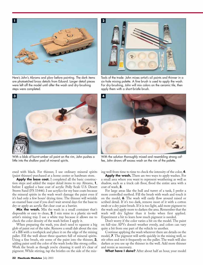
Direct from the streets of Baghdad, the M1A1 Abrams tank! John used the Tamiya mine-plow version with extra detailing parts from Eduard and AFV Club tracks. A thorough wash and dry-brush finish makes this model lookas though it just rumbled into your living room.
M1Abrams
© 2009 Kalmbach Publishing Co. This material may not be reproduced in any form without permission from the publisher. www.FineScale.com

The model. Building and detailing the model was straightforward. I started withthe version of the Tamiya M1A1 kit equipped with a mine plow (No. 35158). The kitis more than 10 years old, and though it’s fairly accurate, I decided to update it withEduard’s photoetched brass detail set (No. 35-333). Eduard even includes the louver-like protrusions on the turret for the infrared IFF (identification friend or foe) devicesused on Iraqi Freedom coalition vehicles – the kind of detail that benefits from thewash-and-dry-brush process.
The kit’s tracks have guide teeth incorrectly located in the middle of the trackblocks instead of between them, but fortunately I found an AFV Club set of T-158tracks (No. AF3512) that are more accurate for M1A1s in service today.
Despite extensive media coverage of the war, I had some difficulty coming up withmarkings for my M1A1. Eventually, I found a photo in a special edition of U.S. Newsand World Report showing several M1s apparently with the 2nd Brigade of the 3rdInfantry. Like their Desert Storm predecessors, Iraqi Freedom M1s are loaded withexternal stores that seem to include everything but the kitchen sink. I gave my Abramsa pile of accessories from Greif ’s “Modern U.S.Tank Crew Gear” set (No. GF004) andthe Academy “Tank Supplies II” set (No. 1383), but it still looks underdressed!
Coming out with the wash. The first phase in finishing my M1 was to applythe wash. A wash is simply highly thinned pigment – mostly thinner and only a touchof pigment – applied over the base coat. Just about any water- or oil-based paint canbe used in a wash – enamels, acrylics, watercolors, or artist’s oils. I’ve tried the exoticmixtures some modelers use, like chalk pastels diluted in lacquer thinner, but I preferthe artist’s oils.
Artist’s oils have several advantages that make them ideal for washes: opacity,intense colors, and finely ground pigments. Many modelers fear the long drying timesof oil paints, but when thinned as they are for a wash, they dry in a few hours.
Compared to modeling paints, artist’s oils are expensive, but only a small amount isneeded to do an entire model. One tube will usually last you for years, and you don’tneed many colors. Most of my washes are made using burnt umber (dark brown) dark-
July 2003 www.finescale.com 21
1/35 Scale
You’ve spent hours researching, building, anddetailing your latest kit only to watch all the
fine detail disappear when you paint it. Theproblem is that details on small objects likemodels don’t cast shadows large enough to dis-tinguish them from the surrounding area. The solution is to apply a wash and use dry-brushing to enhanceshadows and highlights on your model. These techniques will make that hidden detail pop out and repro-duce some of the effects of weathering at the same time.
The process requires no expensive tools and only a few supplies,some of which you already have on your workbench. I’ll demonstrateit on a timely subject: an M1A1 Abrams tank, the spearhead of U.S.armor forces in Operation Iraqi Freedom.
Finishing techniques reveal your hard-earned detailStory by John Plzak
Photos by William Zuback and Jim Forbes
22 FineScale Modeler July 2003
ened with black. For thinner, I use ordinary mineral spirits(paint thinner) purchased at a home center or hardware store.
Apply the base coat. I completed all the basic construc-tion steps and added the major detail items to my Abrams, 1,before I applied a base coat of acrylic Polly Scale U.S. DesertStorm Sand (FS 33446). I use acrylics for my base coats becausethe mineral spirits in the wash won’t damage the paint even ifit’s had only a few hours’ drying time. The thinner will wrinklean enamel base coat if you don’t wait several days for the base todry or apply an acrylic flat clear coat as a barrier.
Mix the wash. Mix the wash in a small container that’sdisposable or easy to clean, 2. I mix mine in a plastic six-wellartist’s mixing tray. I use a white tray because it allows me tocheck the color density of the wash before I apply it.
When preparing the wash, you don’t need to squeeze a bigglob of paint out of the tube. Remove a small dab about the sizeof a BB with a toothpick and place it on the edge of the mixingpallet. Fill the well about three-quarters full of mineral spirits.Using a fine brush, stir some of the paint into the thinner, 3,adding paint until the color of the wash looks like strong coffee.Work the brush as though you’re cleaning it until it’s clear ofpigment. While stirring, tap the bristles on the side of the mix-
ing well from time to time to check the intensity of the color, 4.Apply the wash. There are two ways to apply washes. For
a small area where you want to represent weathering as well asshadow, such as a truck cab floor, flood the entire area with acoat of wash, 5.
For large areas like the hull and turret of a tank, I prefer amore controlled method. Fill the brush with wash and touch iton the model, 6. The wash will easily flow around raised orscribed detail. If it’s too dark, remove most of it with a cottonswab or a dry paint brush. If it is too light, add more pigment tothe wash and apply more to darken the area. Remember that thewash will dry lighter than it looks when first applied.Experiment a bit to learn how much pigment is needed.
Don’t worry if the color varies a bit on the model. The painton full-size AFVs doesn’t weather evenly, and colors can varyquite a bit from one part of the vehicle to another.
Continue applying the wash wherever there are details on themodel, 7. The pigment will settle quickly in the mixing well, sostir often and test it frequently on the pallet. The wash will alsodarken as you use up the thinner in the well. Add more thinnerand remix as necessary.
What have I done? After about half an hour, your model
With a blob of burnt-umber oil paint on the rim, John pushes alittle into the shallow pool of mineral spirits.
With the solution thoroughly mixed and resembling strong cof-fee, John draws off excess wash on the rim of the palette.
Here’s John’s Abrams and plow before painting. The dark itemsare photoetched brass details from Eduard. Larger detail pieceswere left off the model until after the wash and dry-brushingsteps were completed.
Tools of the trade: John mixes artist’s oil paints and thinner in asix-hole mixing palette. A fine brush is used to apply the wash.For dry-brushing, John will mix colors on the ceramic tile, thenapply them with a short-bristle brush.
1 2
3 4
July 2003 www.finescale.com 23
will look awful – very uneven and blotchy. Don’t panic! Yourhard work is not ruined. Let it dry for another hour or two, thentake a cotton swab dampened with mineral spirits and carefullygo over the entire model, 8. Don’t rub too hard or you may rubthrough the paint. Pay particular attention to the large flat areasof the model. You just want to cover the model with a thin coatof thinner, and gently remove the wash from the areas where itdoesn’t belong.
When the thinner dries, the wash will be much more even.Let it all dry overnight before you move on to dry-brushing themodel.
Dry-brush fundamentals. The second phase of the fin-ishing process, dry-brushing, is almost the opposite of a wash.Paint is applied to the brush, then removed until almost none isleft. The brush should be dry, hence the term “dry-brush.” Asthe brush is passed over the model, small amounts of paint col-lect on the high points of the details (see photo 5).
Dry-brushing can be done with either enamels or acrylics. Iuse acrylics for small jobs like tires or road wheels, but for largeareas I find enamels mixed with artist’s oils work best. Enamelsgive me access to a wide variety of colors, while the oils willincrease the paint’s blending ability and working time.
The fine brush transfers the wash to the recessed detail of thehull. When properly thinned, the wash should flow quicklyaround hatches and along recessed panel lines.
The wash has been applied to all the topside detail on the hull. Itlooks messy now, but don’t fret! The excess will be cleaned up inthe next step.
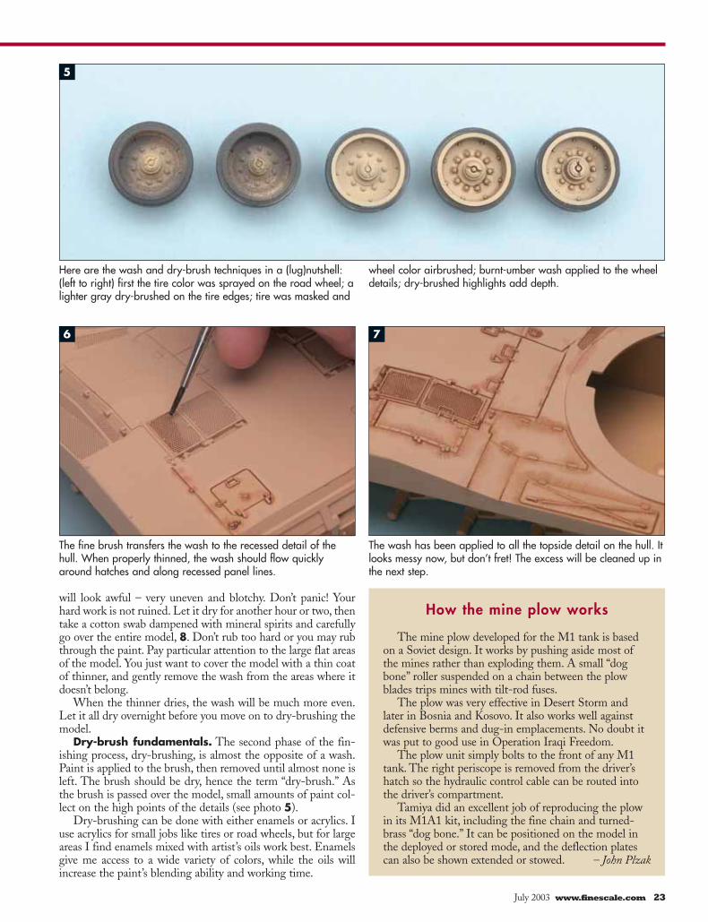
Here are the wash and dry-brush techniques in a (lug)nutshell:(left to right) first the tire color was sprayed on the road wheel; alighter gray dry-brushed on the tire edges; tire was masked and
wheel color airbrushed; burnt-umber wash applied to the wheeldetails; dry-brushed highlights add depth.
How the mine plow works
The mine plow developed for the M1 tank is basedon a Soviet design. It works by pushing aside most ofthe mines rather than exploding them. A small “dogbone” roller suspended on a chain between the plowblades trips mines with tilt-rod fuses.
The plow was very effective in Desert Storm andlater in Bosnia and Kosovo. It also works well againstdefensive berms and dug-in emplacements. No doubt itwas put to good use in Operation Iraqi Freedom.
The plow unit simply bolts to the front of any M1tank. The right periscope is removed from the driver’shatch so the hydraulic control cable can be routed intothe driver’s compartment.
Tamiya did an excellent job of reproducing the plowin its M1A1 kit, including the fine chain and turned-brass “dog bone.” It can be positioned on the model inthe deployed or stored mode, and the deflection platescan also be shown extended or stowed. – John Plzak
5
6 7

24 FineScale Modeler July 2003
You don’t need a lot of oil colors in your pallet; you’ll mainlyuse white. Yellow ochre is useful when working with greensbecause it will keep the white from bleaching out the color. I liketo mix the paint on an old piece of white glazed wall tile. Aswith the wash, the white surface helps me check the color. Thetile also won’t absorb paint and is easy to clean when I’m done.Small, stiff, flat brushes with short bristles work best.
Scrub-a-dub. Find a paint close to your base color (it does-n’t have to be a perfect match). A small amount is needed, so usea toothpick to scoop out a dab of the pigment that has settled tothe bottom of the bottle. Place a dab of white oil paint next tothe enamel and use your brush to mix in a bit of the white untilthe enamel is only slightly lighter than the base color.
Load the brush with the mixture and wipe off the excesspaint on a piece of paper, rag, or paper towel. You want toremove almost all of the paint from the brush.
Start brushing the model, paying particular attention toscrubbing over the raised detail and edges, 9. It takes a littlepractice to learn how much paint you should have on the brushand how much pressure you should apply to the brush. Use
more pressure if the results build up too slowly.Go over the entire model, then add more white to
the base and go over everything again, this timeusing less pressure. Add even more white and do alight third pass just on the high points. Take care: Ifyou put down too much of the final color, your model may endup looking frosted. Let it dry overnight, and if the finish looksa little too uneven the next day, apply a topcoat of your favoriteclear flat.
Make it metallic. One of the best ways to replicatemetal is to dry-brush the parts with metallic enamels.Two of my favorites are Testor steel from the bottle andTestor chrome silver from the paint marker.
Begin by applying a coat of flat black paint to theparts to be metalized. Put some of the metallic painton your pallet, pick up a bit with the brush, wipe thebrush almost dry, and work it over the details. To use thepaint from the pen, I simply push in the nib severaltimes on my tile pallet until I have a small puddle ofpaint to work with.
You’ll be amazed at how realistic items like shovels,tow cables, and track links can be made to look usingthis method, 10.
These finishing techniques are not difficult to learn.They will give the appearance of any model a shot ofrealism and show off the fine detail molded into modernkits. Practice them a bit, and soon people who see yourmodels will say, “Look at all the detail! How did you dothat?” FSM
REFERENCESM1 Abrams Main Battle Tank, 1982-92 (New VanguardNo. 2) Steve Zaloga and Peter Sarson, Osprey PublishingCo., 1993War Machines No. 6: M1-M1IP-M1A1 Abrams MainBattle Tank François Verlinden, Verlinden Productions, 1991M1 Abrams in Action Jim Mesko, Squadron/SignalPublications, Carrollton, Texas, 1991Missing Links M1/M1A1/M1A2 Abrams Tweaks List PeteBeccera, Maj. John Charvat, Matthew Malagorski, andStephen Tyliszczak, www.missing-lynx.com/library/modern/l-modern.htm
After waiting an hour or two for the mineral spirits to dry, Johnwipes off the excess wash with a thinner-dampened cotton swab.
With most of the pigment removed from the flat brush, a lightgrazing of Testor steel enamel on this tow cable shows howeffective a good dry-brush technique can be.
Here’s the finished mine plow, effectively washed and dry-brushed. Note the metallic sheen of the plow blades, createdwith a dry-brushing of Testor chrome silver.
8 9
10
July 2003 www.finescale.com 25
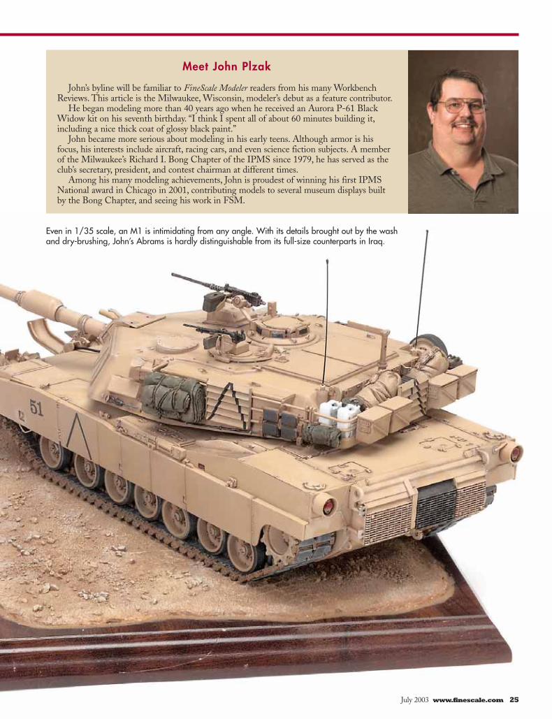
Meet John Plzak
John’s byline will be familiar to FineScale Modeler readers from his many WorkbenchReviews. This article is the Milwaukee, Wisconsin, modeler’s debut as a feature contributor.
He began modeling more than 40 years ago when he received an Aurora P-61 BlackWidow kit on his seventh birthday. “I think I spent all of about 60 minutes building it,including a nice thick coat of glossy black paint.”
John became more serious about modeling in his early teens. Although armor is hisfocus, his interests include aircraft, racing cars, and even science fiction subjects. A memberof the Milwaukee’s Richard I. Bong Chapter of the IPMS since 1979, he has served as theclub’s secretary, president, and contest chairman at different times.
Among his many modeling achievements, John is proudest of winning his first IPMSNational award in Chicago in 2001, contributing models to several museum displays builtby the Bong Chapter, and seeing his work in FSM.
Even in 1/35 scale, an M1 is intimidating from any angle. With its details brought out by the washand dry-brushing, John’s Abrams is hardly distinguishable from its full-size counterparts in Iraq.
© 2009 Kalmbach Publishing Co. This material may not be reproduced in any form without permission from the publisher. www.FineScale.com


an M109A6 PaladinCombine aftermarket parts and modeling
skills to transform a basic kit into a detailed masterpiece
By Bart Cusumano
Bart takes his Paladin to the next level with a few simple aftermarket parts.
Punch uP
© 2009 Kalmbach Publishing Co. This material may not be reproduced in any form without permission from the publisher. www.FineScale.com
1 2
43
Getting StartedI am amazed at the improvements in plas-tic kits over the years. Despite the new tooling and moldings, I still like to give my models extra details that are usually not provided with box-stock materials.
I decided to dress up Italeri’s 1/35 scale M109A6 Paladin (kit No. 372) with Eduard’s photoetched set (No. 35-319) made specifically for the Italeri kit, Skybow T-136 individual-link tracks (No. TP3502), along with scratchbuilt addi-tions of resin parts, sheet plastic, brass rod, and copper wire.
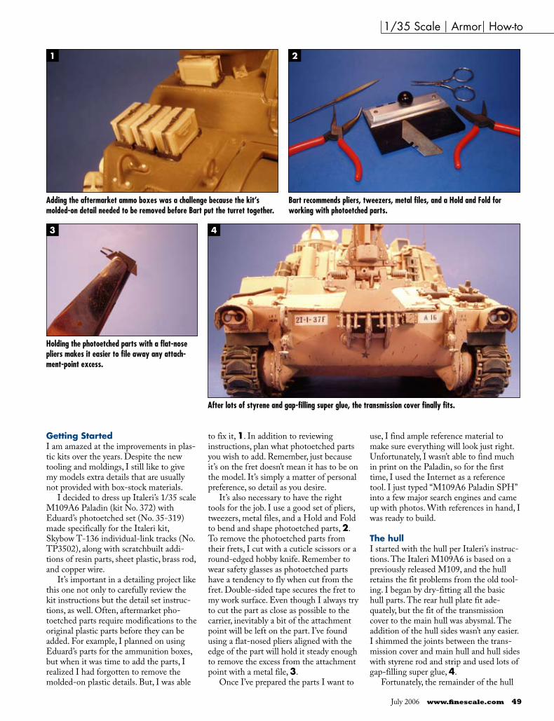
It’s important in a detailing project like this one not only to carefully review the kit instructions but the detail set instruc-tions, as well. Often, aftermarket pho-toetched parts require modifications to the original plastic parts before they can be added. For example, I planned on using Eduard’s parts for the ammunition boxes, but when it was time to add the parts, I realized I had forgotten to remove the molded-on plastic details. But, I was able
to fix it, 1. In addition to reviewing instructions, plan what photoetched parts you wish to add. Remember, just because it’s on the fret doesn’t mean it has to be on the model. It’s simply a matter of personal preference, so detail as you desire.
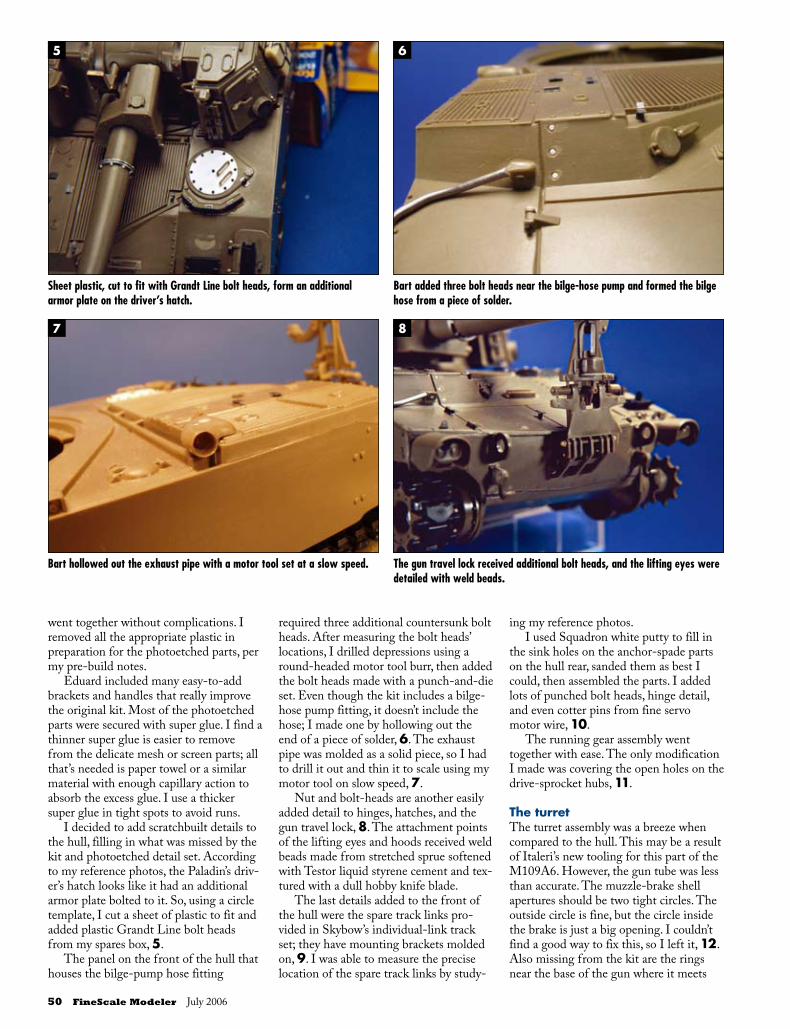
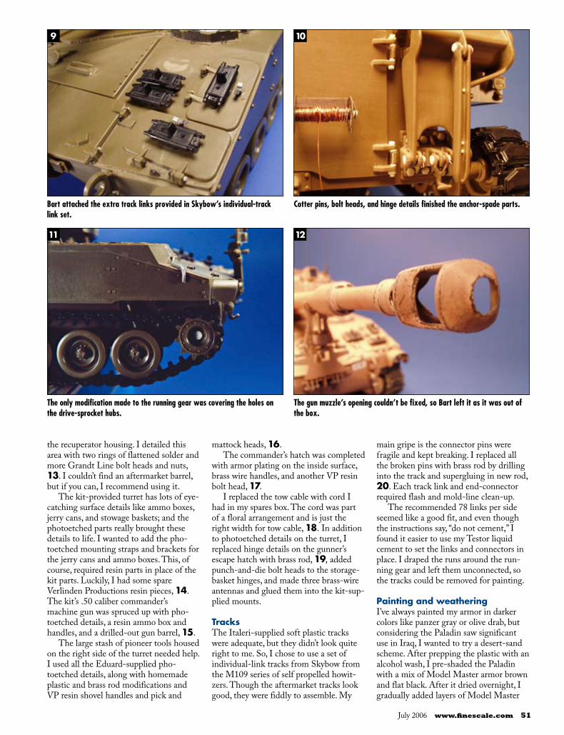
It’s also necessary to have the right tools for the job. I use a good set of pliers, tweezers, metal files, and a Hold and Fold to bend and shape photoetched parts, 2. To remove the photoetched parts from their frets, I cut with a cuticle scissors or a round-edged hobby knife. Remember to wear safety glasses as photoetched parts have a tendency to fly when cut from the fret. Double-sided tape secures the fret to my work surface. Even though I always try to cut the part as close as possible to the carrier, inevitably a bit of the attachment point will be left on the part. I’ve found using a flat-nosed pliers aligned with the edge of the part will hold it steady enough to remove the excess from the attachment point with a metal file, 3.
Once I’ve prepared the parts I want to
use, I find ample reference material to make sure everything will look just right. Unfortunately, I wasn’t able to find much in print on the Paladin, so for the first time, I used the Internet as a reference tool. I just typed “M109A6 Paladin SPH” into a few major search engines and came up with photos. With references in hand, I was ready to build.
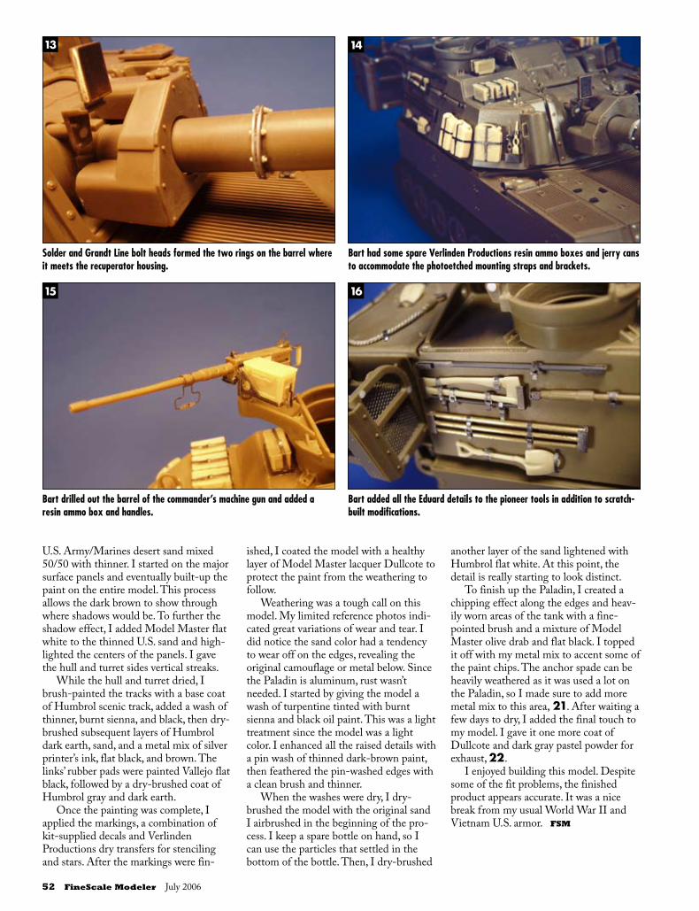
The hullI started with the hull per Italeri’s instruc-tions. The Italeri M109A6 is based on a previously released M109, and the hull retains the fit problems from the old tool-ing. I began by dry-fitting all the basic hull parts. The rear hull plate fit ade-quately, but the fit of the transmission cover to the main hull was abysmal. The addition of the hull sides wasn’t any easier. I shimmed the joints between the trans-mission cover and main hull and hull sides with styrene rod and strip and used lots of gap-filling super glue, 4.
Fortunately, the remainder of the hull
1/35 Scale | Armor| How-to
Adding the aftermarket ammo boxes was a challenge because the kit’s molded-on detail needed to be removed before Bart put the turret together.
Bart recommends pliers, tweezers, metal files, and a Hold and Fold for working with photoetched parts.
Holding the photoetched parts with a flat-nose pliers makes it easier to file away any attach-ment-point excess.
After lots of styrene and gap-filling super glue, the transmission cover finally fits.
July 2006 www.finescale.com 49
5 6
7 8
went together without complications. I removed all the appropriate plastic in preparation for the photoetched parts, per my pre-build notes.
Eduard included many easy-to-add brackets and handles that really improve the original kit. Most of the photoetched parts were secured with super glue. I find a thinner super glue is easier to remove from the delicate mesh or screen parts; all that’s needed is paper towel or a similar material with enough capillary action to absorb the excess glue. I use a thicker super glue in tight spots to avoid runs.
I decided to add scratchbuilt details to the hull, filling in what was missed by the kit and photoetched detail set. According to my reference photos, the Paladin’s driv-er’s hatch looks like it had an additional armor plate bolted to it. So, using a circle template, I cut a sheet of plastic to fit and added plastic Grandt Line bolt heads from my spares box, 5.
The panel on the front of the hull that houses the bilge-pump hose fitting
required three additional countersunk bolt heads. After measuring the bolt heads’ locations, I drilled depressions using a round-headed motor tool burr, then added the bolt heads made with a punch-and-die set. Even though the kit includes a bilge-hose pump fitting, it doesn’t include the hose; I made one by hollowing out the end of a piece of solder, 6. The exhaust pipe was molded as a solid piece, so I had to drill it out and thin it to scale using my motor tool on slow speed, 7.
Nut and bolt-heads are another easily added detail to hinges, hatches, and the gun travel lock, 8. The attachment points of the lifting eyes and hoods received weld beads made from stretched sprue softened with Testor liquid styrene cement and tex-tured with a dull hobby knife blade.
The last details added to the front of the hull were the spare track links pro-vided in Skybow’s individual-link track set; they have mounting brackets molded on, 9. I was able to measure the precise location of the spare track links by study-
ing my reference photos. I used Squadron white putty to fill in
the sink holes on the anchor-spade parts on the hull rear, sanded them as best I could, then assembled the parts. I added lots of punched bolt heads, hinge detail, and even cotter pins from fine servo motor wire, 10.
The running gear assembly went together with ease. The only modification I made was covering the open holes on the drive-sprocket hubs, 11.
The turretThe turret assembly was a breeze when compared to the hull. This may be a result of Italeri’s new tooling for this part of the M109A6. However, the gun tube was less than accurate. The muzzle-brake shell apertures should be two tight circles. The outside circle is fine, but the circle inside the brake is just a big opening. I couldn’t find a good way to fix this, so I left it, 12. Also missing from the kit are the rings near the base of the gun where it meets
Sheet plastic, cut to fit with Grandt Line bolt heads, form an additional armor plate on the driver’s hatch.
Bart added three bolt heads near the bilge-hose pump and formed the bilge hose from a piece of solder.
Bart hollowed out the exhaust pipe with a motor tool set at a slow speed. The gun travel lock received additional bolt heads, and the lifting eyes were detailed with weld beads.
50 FineScale Modeler July 2006
9 10
11 12
the recuperator housing. I detailed this area with two rings of flattened solder and more Grandt Line bolt heads and nuts, 13. I couldn’t find an aftermarket barrel, but if you can, I recommend using it.
The kit-provided turret has lots of eye-catching surface details like ammo boxes, jerry cans, and stowage baskets; and the photoetched parts really brought these details to life. I wanted to add the pho-toetched mounting straps and brackets for the jerry cans and ammo boxes. This, of course, required resin parts in place of the kit parts. Luckily, I had some spare Verlinden Productions resin pieces, 14. The kit’s .50 caliber commander’s machine gun was spruced up with pho-toetched details, a resin ammo box and handles, and a drilled-out gun barrel, 15.
The large stash of pioneer tools housed on the right side of the turret needed help. I used all the Eduard-supplied pho-toetched details, along with homemade plastic and brass rod modifications and VP resin shovel handles and pick and
mattock heads, 16.The commander’s hatch was completed
with armor plating on the inside surface, brass wire handles, and another VP resin bolt head, 17.
I replaced the tow cable with cord I had in my spares box. The cord was part of a floral arrangement and is just the right width for tow cable, 18. In addition to photoetched details on the turret, I replaced hinge details on the gunner’s escape hatch with brass rod, 19, added punch-and-die bolt heads to the storage-basket hinges, and made three brass-wire antennas and glued them into the kit-sup-plied mounts.
TracksThe Italeri-supplied soft plastic tracks were adequate, but they didn’t look quite right to me. So, I chose to use a set of individual-link tracks from Skybow from the M109 series of self propelled howit-zers. Though the aftermarket tracks look good, they were fiddly to assemble. My
main gripe is the connector pins were fragile and kept breaking. I replaced all the broken pins with brass rod by drilling into the track and supergluing in new rod, 20. Each track link and end-connector required flash and mold-line clean-up.
The recommended 78 links per side seemed like a good fit, and even though the instructions say, “do not cement,” I found it easier to use my Testor liquid cement to set the links and connectors in place. I draped the runs around the run-ning gear and left them unconnected, so the tracks could be removed for painting.
Painting and weatheringI’ve always painted my armor in darker colors like panzer gray or olive drab, but considering the Paladin saw significant use in Iraq, I wanted to try a desert-sand scheme. After prepping the plastic with an alcohol wash, I pre-shaded the Paladin with a mix of Model Master armor brown and flat black. After it dried overnight, I gradually added layers of Model Master
Bart attached the extra track links provided in Skybow’s individual-track link set.
Cotter pins, bolt heads, and hinge details finished the anchor-spade parts.
The only modification made to the running gear was covering the holes on the drive-sprocket hubs.
The gun muzzle’s opening couldn’t be fixed, so Bart left it as it was out of the box.
July 2006 www.finescale.com 51
13 14
15 16
U.S. Army/Marines desert sand mixed 50/50 with thinner. I started on the major surface panels and eventually built-up the paint on the entire model. This process allows the dark brown to show through where shadows would be. To further the shadow effect, I added Model Master flat white to the thinned U.S. sand and high-lighted the centers of the panels. I gave the hull and turret sides vertical streaks.
While the hull and turret dried, I brush-painted the tracks with a base coat of Humbrol scenic track, added a wash of thinner, burnt sienna, and black, then dry-brushed subsequent layers of Humbrol dark earth, sand, and a metal mix of silver printer’s ink, flat black, and brown. The links’ rubber pads were painted Vallejo flat black, followed by a dry-brushed coat of Humbrol gray and dark earth.
Once the painting was complete, I applied the markings, a combination of kit-supplied decals and Verlinden Productions dry transfers for stenciling and stars. After the markings were fin-
ished, I coated the model with a healthy layer of Model Master lacquer Dullcote to protect the paint from the weathering to follow.
Weathering was a tough call on this model. My limited reference photos indi-cated great variations of wear and tear. I did notice the sand color had a tendency to wear off on the edges, revealing the original camouflage or metal below. Since the Paladin is aluminum, rust wasn’t needed. I started by giving the model a wash of turpentine tinted with burnt sienna and black oil paint. This was a light treatment since the model was a light color. I enhanced all the raised details with a pin wash of thinned dark-brown paint, then feathered the pin-washed edges with a clean brush and thinner.
When the washes were dry, I dry-brushed the model with the original sand I airbrushed in the beginning of the pro-cess. I keep a spare bottle on hand, so I can use the particles that settled in the bottom of the bottle. Then, I dry-brushed
another layer of the sand lightened with Humbrol flat white. At this point, the detail is really starting to look distinct.
To finish up the Paladin, I created a chipping effect along the edges and heav-ily worn areas of the tank with a fine-pointed brush and a mixture of Model Master olive drab and flat black. I topped it off with my metal mix to accent some of the paint chips. The anchor spade can be heavily weathered as it was used a lot on the Paladin, so I made sure to add more metal mix to this area, 21. After waiting a few days to dry, I added the final touch to my model. I gave it one more coat of Dullcote and dark gray pastel powder for exhaust, 22.
I enjoyed building this model. Despite some of the fit problems, the finished product appears accurate. It was a nice break from my usual World War II and Vietnam U.S. armor. FSM
Solder and Grandt Line bolt heads formed the two rings on the barrel where it meets the recuperator housing.
Bart had some spare Verlinden Productions resin ammo boxes and jerry cans to accommodate the photoetched mounting straps and brackets.
Bart drilled out the barrel of the commander’s machine gun and added a resin ammo box and handles.
Bart added all the Eduard details to the pioneer tools in addition to scratch-built modifications.
52 FineScale Modeler July 2006

17 18
19 20 21
22
An armor plate, brass-wire handles, and a Verlinden Productions resin bolt head finished the commander’s hatch.
A piece of floral arranging cord was the right size for the tow cable.
A brass rod replaced the hinge on the gunner’s escape hatch.
Bart substituted brass rod for the fragile connector pins.
The anchor spade was used often on the Paladin, so Bart weathered this area heavily.
Exhaust made of dark-gray pastel powder pro-vided the finishing touch on Bart’s Paladin.
With some photoetched parts, resin pieces, and planning, Bart completed a precisely detailed M109A6.
SOuRcESEduard photoetched set (No. 35-319), 420-47-611-8259, www.eduard.comThe Small Shop Hold and Fold, (44) (0)1747 825 646, www.smallshopu.comGrandt Line Bolts, 925-671-0143, www.grandtline.comSkybow T-136 individual link tracks (No. TP3502), 142 Nanyuan St., Tainan City, TaiwanVerlinden Productions various resin pieces, 636-379-0077, www.verlinden-productions.com
July 2006 www.finescale.com 53

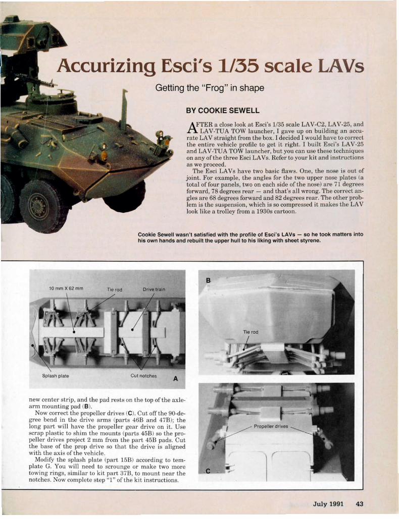
18 FineScale Modeler October 2007 October 2007 www.finescale.com 1918 FineScale Modeler October 2007 October 2007 www.finescale.com 19
Up-armoring Tamiya’s HumveeScratchbuilding armor and other details for a 2004 Baghdad patroller
By Aaron Skinner
As the Huey helicopter was in Vietnam, the Humvee is ubiquitous in the Iraq War. Early in the conflict,
many Humvees went into action with little or no armor. In late 2003 and early 2004, insurgent attacks had the military looking for ways to boost protection for soldiers. While production of the M1114 Up-Armored Humvee ramped up, kits for armoring the older, unprotected vehicles began arriving in the Middle East.
Scratchbuilt armor, detailed weapons, and extra stow-age mark Aaron’s model as a Humvee which served with the Arkansas National Guard in Iraq in 2004.
© 2009 Kalmbach Publishing Co. This material may not be reproduced in any form without permission from the publisher. www.FineScale.com

1 2 3
4 5
6 7 8
18 FineScale Modeler October 2007 October 2007 www.finescale.com 1918 FineScale Modeler October 2007 October 2007 www.finescale.com 19
One of these was the ASK (Armor Survivability Kit) developed by the Army’s Research Development and Engineering Command.
I wanted to model a Humvee of Arkansas’ 39th Infantry Brigade during 2004, including ASK, extra stowage, and correct armament, 1. Scratchbuilding seemed the best approach because the vehicle I was modeling – a four-door hardtop of Delta Company, 3rd Battalion, with Sally emblazoned above the wind-shield – had several unique features not included in aftermarket detail sets.
Setting aside my trepidation about a project this large, I commenced building, starting with Tamiya’s 1/35 scale M1025 Humvee Armament Carrier (Kit No.
MM-263) and Eduard’s photoetched-metal detail set.
Low riderThe ASK’s steel armor added 1,300 pounds to the vehicle, causing these Humvees to sit noticeably lower.
Tamiya’s suspension components are molded into place on the frames. Starting with a saw, I cut between the upper wish-bone arms and their brackets, 2. After opening up holes with a small bit, I used a piece of thread to complete the cut, 3, then cleaned up the brackets.
The join between the lower arms and their frames is more complicated, so I decided to sacrifice a second kit. I clipped the arms off below the bracket, 4. This
leaves two beams for front and back that are easily cleaned up before being glued onto the chassis. Lower arms were cut from the suspension of the second Humvee kit, 5.
Tamiya molded the springs as single pieces with mounts and shock absorbers. I cut the spring from the mount, then drilled a locating hole for the shock absorber in the mount. Telescoping sec-tions of brass round make up the shock absorbers, 6. For springs, I wound straightened paper clips around a .10" sec-tion of Mission Models’ small Multi-Tool, 7. I cut the axles from the differentials.
I installed the new shocks, then reas-sembled the other suspension components around them, 8.
Paper clips, straightened then wound around a mandrel, produced scale springs that were eas-ily compressed to fit their space.
The inspiration: A Humvee of Delta Company, 3rd Battalion, Arkansas’ 39th Infantry Brigade, seen here at a base in Baghdad in June 2004.
To lower the suspension, Aaron separates the suspension arms from their brackets with a razor saw.
Sewing thread completes the cut to remove the arm from the chassis. The thread is easy to con-trol and reaches areas a saw can’t.
Using side clippers, Aaron removes a lower wishbone from the frame. Doing this necessi-tated opening a second kit for more arms.
The suspension components laid out after the modifying cuts were made: The suspension parts looked similar and were easy to confuse, so Aaron labeled each part to ensure it ended up in the right location when he reassembled the Humvee’s chassis.
A 7mm section of 1⁄16" brass rod telescoped inside a 5mm section of 3⁄32" brass round to make the shock absorbers.
Springs and shock absorbers in position: The bowed, unevenly compressed springs match Aaron’s photos of Iraq War vehicles.
1/35 Scale | Armor | How To
9
20 FineScale Modeler October 2007 October 2007 www.finescale.com 2120 FineScale Modeler October 2007 October 2007 www.finescale.com 21
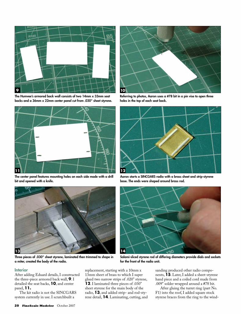
InteriorAfter adding Eduard details, I constructed the three-piece armored back wall, 9. I detailed the seat backs, 10, and center panel, 11.
The kit radio is not the SINCGARS system currently in use. I scratchbuilt a
replacement, starting with a 10mm x 13mm sheet of brass to which I super glued two narrow strips of .020" styrene, 12. I laminated three pieces of .030" sheet styrene for the main body of the radio, 13, and added strip- and rod-sty-rene detail, 14. Laminating, cutting, and
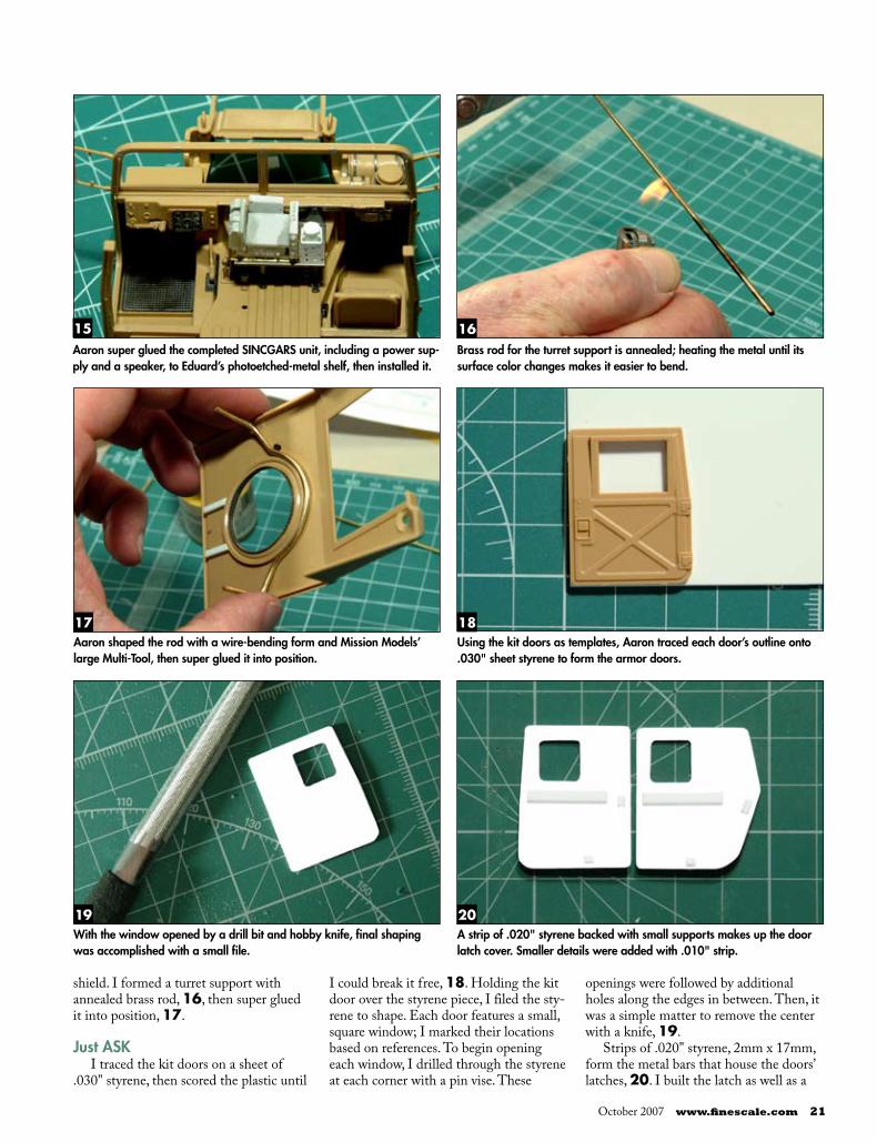
sanding produced other radio compo-nents, 15. Later, I added a sheet-styrene hand piece and a coiled cord made from .009" solder wrapped around a #78 bit.
After gluing the turret ring (part No. F1) into the roof, I added square stock styrene braces from the ring to the wind-
10
11 12
13 14
Referring to photos, Aaron uses a #78 bit in a pin vise to open three holes in the top of each seat back.
The center panel features mounting holes on each side made with a drill bit and opened with a knife.
Aaron starts a SINCGARS radio with a brass sheet and strip-styrene base. The ends were shaped around brass rod.
Three pieces of .030" sheet styrene, laminated then trimmed to shape in a miter, created the body of the radio.
Salami-sliced styrene rod of differing diameters provide dials and sockets for the front of the radio unit.
The Humvee’s armored back wall consists of two 14mm x 33mm seat backs and a 36mm x 22mm center panel cut from .030" sheet styrene.
20 FineScale Modeler October 2007 October 2007 www.finescale.com 2120 FineScale Modeler October 2007 October 2007 www.finescale.com 21
shield. I formed a turret support with annealed brass rod, 16, then super glued it into position, 17.
Just ASKI traced the kit doors on a sheet of
.030" styrene, then scored the plastic until
I could break it free, 18. Holding the kit door over the styrene piece, I filed the sty-rene to shape. Each door features a small, square window; I marked their locations based on references. To begin opening each window, I drilled through the styrene at each corner with a pin vise. These
openings were followed by additional holes along the edges in between. Then, it was a simple matter to remove the center with a knife, 19.
Strips of .020" styrene, 2mm x 17mm, form the metal bars that house the doors’ latches, 20. I built the latch as well as a
15 16
17 18
Brass rod for the turret support is annealed; heating the metal until its surface color changes makes it easier to bend.
Aaron super glued the completed SINCGARS unit, including a power sup-ply and a speaker, to Eduard’s photoetched-metal shelf, then installed it.
Aaron shaped the rod with a wire-bending form and Mission Models’ large Multi-Tool, then super glued it into position.
Using the kit doors as templates, Aaron traced each door’s outline onto .030" sheet styrene to form the armor doors.
19 20With the window opened by a drill bit and hobby knife, final shaping was accomplished with a small file.
A strip of .020" styrene backed with small supports makes up the door latch cover. Smaller details were added with .010" strip.
22 FineScale Modeler October 2007 October 2007 www.finescale.com 2322 FineScale Modeler October 2007 October 2007 www.finescale.com 23
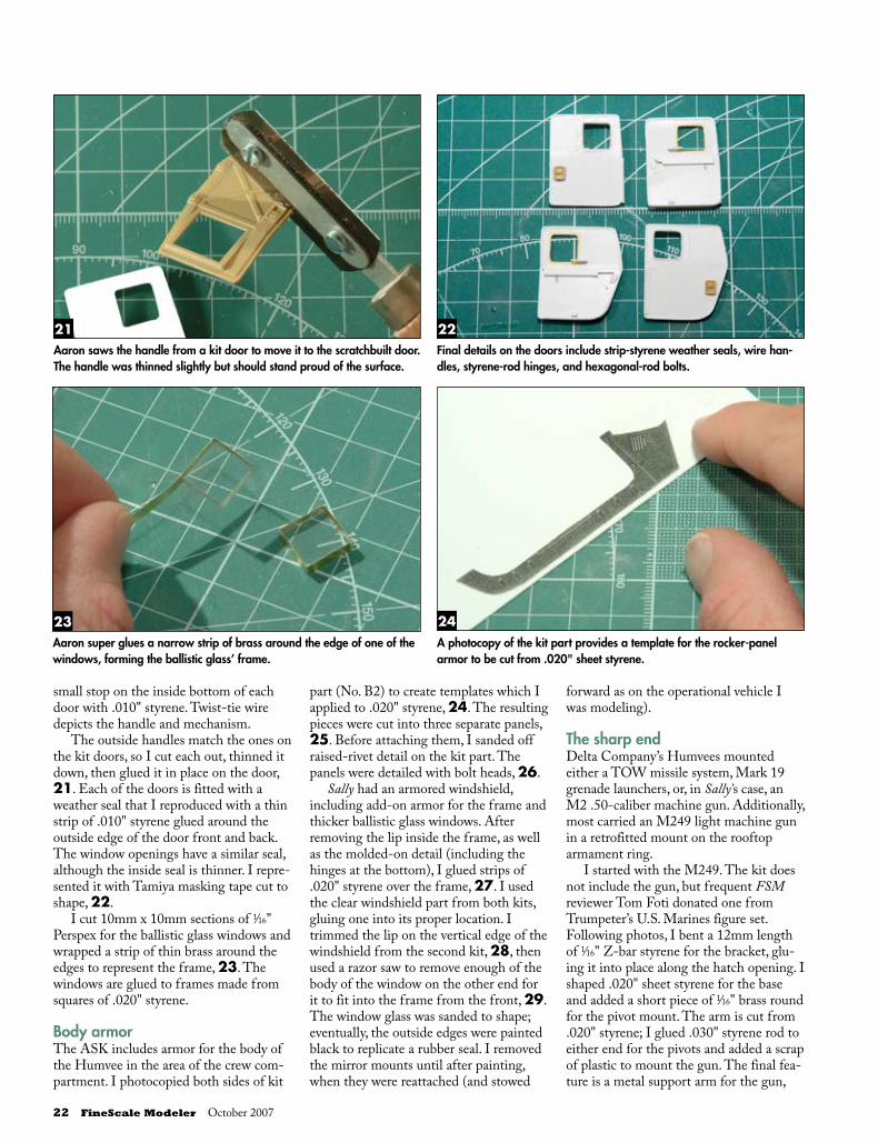
small stop on the inside bottom of each door with .010" styrene. Twist-tie wire depicts the handle and mechanism.
The outside handles match the ones on the kit doors, so I cut each out, thinned it down, then glued it in place on the door, 21. Each of the doors is fitted with a weather seal that I reproduced with a thin strip of .010" styrene glued around the outside edge of the door front and back. The window openings have a similar seal, although the inside seal is thinner. I repre-sented it with Tamiya masking tape cut to shape, 22.
I cut 10mm x 10mm sections of 1⁄16" Perspex for the ballistic glass windows and wrapped a strip of thin brass around the edges to represent the frame, 23. The windows are glued to frames made from squares of .020" styrene.
Body armorThe ASK includes armor for the body of the Humvee in the area of the crew com-partment. I photocopied both sides of kit
part (No. B2) to create templates which I applied to .020" styrene, 24. The resulting pieces were cut into three separate panels, 25. Before attaching them, I sanded off raised-rivet detail on the kit part. The panels were detailed with bolt heads, 26.
Sally had an armored windshield, including add-on armor for the frame and thicker ballistic glass windows. After removing the lip inside the frame, as well as the molded-on detail (including the hinges at the bottom), I glued strips of .020" styrene over the frame, 27. I used the clear windshield part from both kits, gluing one into its proper location. I trimmed the lip on the vertical edge of the windshield from the second kit, 28, then used a razor saw to remove enough of the body of the window on the other end for it to fit into the frame from the front, 29. The window glass was sanded to shape; eventually, the outside edges were painted black to replicate a rubber seal. I removed the mirror mounts until after painting, when they were reattached (and stowed
forward as on the operational vehicle I was modeling).
The sharp endDelta Company’s Humvees mounted either a TOW missile system, Mark 19 grenade launchers, or, in Sally’s case, an M2 .50-caliber machine gun. Additionally, most carried an M249 light machine gun in a retrofitted mount on the rooftop armament ring.
I started with the M249. The kit does not include the gun, but frequent FSM reviewer Tom Foti donated one from Trumpeter’s U.S. Marines figure set. Following photos, I bent a 12mm length of 1⁄16" Z-bar styrene for the bracket, glu-ing it into place along the hatch opening. I shaped .020" sheet styrene for the base and added a short piece of 1⁄16" brass round for the pivot mount. The arm is cut from .020" styrene; I glued .030" styrene rod to either end for the pivots and added a scrap of plastic to mount the gun. The final fea-ture is a metal support arm for the gun,
21 22
23 24
Aaron saws the handle from a kit door to move it to the scratchbuilt door. The handle was thinned slightly but should stand proud of the surface.
Final details on the doors include strip-styrene weather seals, wire han-dles, styrene-rod hinges, and hexagonal-rod bolts.
Aaron super glues a narrow strip of brass around the edge of one of the windows, forming the ballistic glass’ frame.
A photocopy of the kit part provides a template for the rocker-panel armor to be cut from .020" sheet styrene.
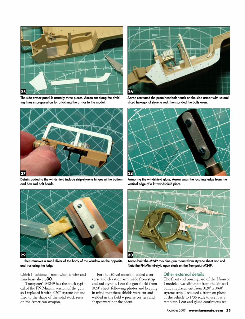
22 FineScale Modeler October 2007 October 2007 www.finescale.com 2322 FineScale Modeler October 2007 October 2007 www.finescale.com 23
28
29 30
Armoring the windshield glass, Aaron saws the locating ledge from the vertical edge of a kit windshield piece …
… then removes a small sliver of the body of the window on the opposite end, restoring the ledge.
Aaron built the M249 machine-gun mount from styrene sheet and rod. Note the FN Minimi-style open stock on the Trumpeter M249.
25 26
27
The side armor panel is actually three pieces. Aaron cut along the divid-ing lines in preparation for attaching the armor to the model.
Aaron recreated the prominent bolt heads on the side armor with salami-sliced hexagonal styrene rod, then sanded the bolts even.
Details added to the windshield include strip-styrene hinges at the bottom and hex-rod bolt heads.
which I fashioned from twist-tie wire and thin brass sheet, 30.
Trumpeter’s M249 has the stock typi-cal of the FN Minimi version of the gun, so I replaced it with .020" styrene cut and filed to the shape of the solid stock seen on the American weapon.
For the .50-cal mount, I added a tra-verse and elevation arm made from strip and rod styrene. I cut the gun shield from .020" sheet, following photos and keeping in mind that these shields were cut and welded in the field – precise corners and shapes were not the norm.
Other external detailsThe front end brush guard of the Humvee I modeled was different from the kit, so I built a replacement from .020" x .060" styrene strip. I reduced a front-on photo of the vehicle to 1/35 scale to use it as a template. I cut and glued continuous sec-
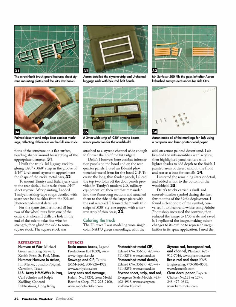
24 FineScale Modeler October 2007 October 2007 www.finescale.com 2524 FineScale Modeler October 2007 October 2007 www.finescale.com 25
31 32 33The scratchbuilt brush guard features sheet sty-rene mounting plates and the kit’s tow hooks.
Aaron detailed the styrene-strip and U-channel luggage rack with hex-rod bolt heads.
Mr. Surfacer 500 fills the gaps left after Aaron kitbashed Tamiya accessories for side CIPs.
34 35 36Painted desert-sand strips bear combat mark-ings, reflecting differences on the full-size truck.
A 2mm-wide strip of .020" styrene boosts armor protection for the windshield.
Aaron made all of the markings for Sally using a computer and laser-printer decal paper.
tions of the structure on a flat surface, bending shapes around brass tubing of the appropriate diameter, 31.
I built the trunk-lid luggage rack by gluing .020" x .060" strip in the groove of 1/16" U-channel styrene to approximate the shape of the rack’s metal bars, 32.
To mount Tamiya and Italeri jerry cans to the rear deck, I built racks from .010" sheet styrene. After painting, I added Tamiya masking-tape straps detailed with spare seat-belt buckles from the Eduard photoetched-metal detail set.
For the spare tire, I removed all but two of the wheel nuts from one of the extra kit’s wheels. I drilled a hole in the end of the axle to take fine wire for strength, then glued the axle to some square stock. The square stock was
attached to a styrene channel wide enough to fit over the lip of the kit tailgate.
Delta’s Humvees bore combat informa-tion panels on the hood and on the rear quarter panels. I used an Eduard pho-toetched-metal item for the hood CIP. To create the long, thin fender panels, I sliced the top two folds off the door panels pro-vided in Tamiya’s modern U.S. military equipment set, then cut that remainder into two 8mm-long sections and attached them to the side of the larger piece with the rail removed. I framed them with thin strips of .030" styrene topped with a nar-row strip of thin brass, 33.
Coloring the truckThe Humvee I was modeling wore single-color NATO green camouflage, with the
add-on armor painted desert sand. I air-brushed the subassemblies with acrylics, then highlighted panel centers with lighter shades to add depth to the finish. I painted areas of desert sand on the front and rear as a base for stencils, 34.
I inserted the remaining interior detail, and added armor to the bottom of the windshield, 35.
Delta’s trucks carried a skull-and-crossed-missiles symbol during the first few months of the 39th’s deployment. I found a clear photo of the symbol, con-verted it to black-and-white using Adobe Photoshop, increased the contrast, then reduced the image to 1/35 scale and saved it. I replicated the image, making minor changes to its outline to represent irregu-larities in its spray application. I used the
REFERENCESHumvee at War, Michael Green and Greg Stewart, Zenith Press, St. Paul, Minn.Hummer Humvee in action, Jim Mesko, Squadron/Signal, Carrolton, TexasU.S. Army HMMWVs in Iraq, Carl Schulze and Ralph Zwilling, Concord Publications, Hong Kong
SOURCESResin ammo boxes, Legend Productions (LF1039), www.www-legend.co.krStowage and CIP, Tamiya (MM-266), 800-826-4922, www.tamiyausa.comJerry cans and stowage, Italeri (No. 6423), from Model Rectifier Corp., 732-225-2100, www.modelrectifier.com
Photoetched-metal CIP, Eduard (No. 35659), 420-47-611-8259, www.eduard.czPhotoetched-metal details, Eduard (No. 35629), 420-47-611-8259, www.eduard.czStyrene sheet, strip, and rod, Evergreen Scale Models, 425-402-4918, www.evergreen-scalemodels.com
Styrene rod, hexagonal rod, and channel, Plastruct, 626-912-7016, www.plastruct.comBrass rod and sheet, K&S Engineering, 773-586-8503, www.ksmetals.comClear decal paper, Experts-Choice (No.123 or 124),248-477-0813,www.bare-metal.com
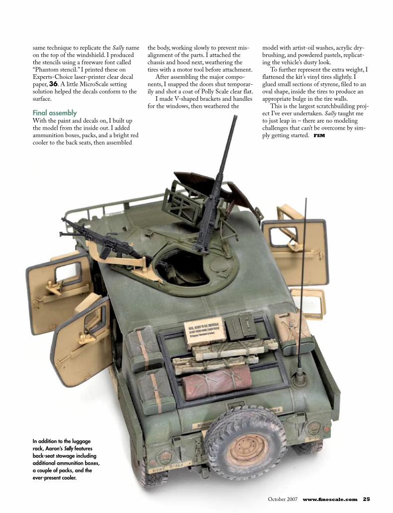
24 FineScale Modeler October 2007 October 2007 www.finescale.com 2524 FineScale Modeler October 2007 October 2007 www.finescale.com 25
In addition to the luggage rack, Aaron’s Sally features back-seat stowage including additional ammunition boxes, a couple of packs, and the ever-present cooler.
same technique to replicate the Sally name on the top of the windshield. I produced the stencils using a freeware font called “Phantom stencil.” I printed these on Experts-Choice laser-printer clear decal paper, 36. A little MicroScale setting solution helped the decals conform to the surface.
Final assemblyWith the paint and decals on, I built up the model from the inside out. I added ammunition boxes, packs, and a bright red cooler to the back seats, then assembled
the body, working slowly to prevent mis-alignment of the parts. I attached the chassis and hood next, weathering the tires with a motor tool before attachment.
After assembling the major compo-nents, I snapped the doors shut temporar-ily and shot a coat of Polly Scale clear flat.
I made V-shaped brackets and handles for the windows, then weathered the
model with artist-oil washes, acrylic dry-brushing, and powdered pastels, replicat-ing the vehicle’s dusty look.
To further represent the extra weight, I flattened the kit’s vinyl tires slightly. I glued small sections of styrene, filed to an oval shape, inside the tires to produce an appropriate bulge in the tire walls.
This is the largest scratchbuilding proj-ect I’ve ever undertaken. Sally taught me to just leap in – there are no modeling challenges that can’t be overcome by sim-ply getting started. FSM
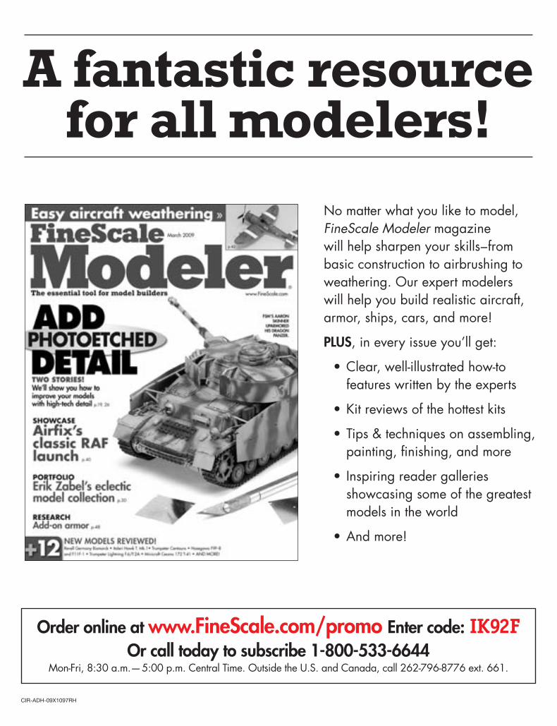
CIR-ADH-09X1097RH
No matter what you like to model,
FineScale Modeler magazine
will help sharpen your skills – from
basic construction to airbrushing to
weathering. Our expert modelers
will help you build realistic aircraft,
armor, ships, cars, and more!
PLUS, in every issue you’ll get:
Clear, well-illustrated how-to
features written by the experts
Kit reviews of the hottest kits
Tips & techniques on assembling,
painting, fi nishing, and more
Inspiring reader galleries
showcasing some of the greatest
models in the world
And more!
•
•
•
•
•
A fantastic resource for all modelers!
Order online at www.FineScale.com/promo Enter code: IK92FOr call today to subscribe 1-800-533-6644
Mon-Fri, 8:30 a.m.— 5:00 p.m. Central Time. Outside the U.S. and Canada, call 262-796-8776 ext. 661.