tests on extruded cables - pesicctests on extruded cables pierre argaut chairman of cigre sc b1...
TRANSCRIPT

Fall ICC, 2011, Denver, Colorado
Tests on Extruded Cables
Pierre Argaut Chairman of CIGRE SC B1
October 26 th, 2011

Fall ICC, 2011, Denver, Colorado
At least, once in your life, you have heard these words: – Development Tests
– Long-term Tests
– Prequalification Tests
– Extension of Qualification Tests
– TypeTests
– Factory Production (Routine) Tests
– Sample tests
– After-installation Tests
– Maintenance or Assessment Tests
– Special-purpose Tests
For a HV or EHV extruded cable system, all of them mean something

Fall ICC, 2011, Denver, Colorado
Design
Construction
Operation
Removal
System design
Rating, Ampacity
Cable & Accessories design
Construction, Installation
Monitoring, Diagnostics
Testing
Operation, Maintenance, Reliability
The 40 years Cable Life Cycle
Manufacturing

Fall ICC, 2011, Denver, Colorado
Contents
1 Introduction
2 What is Electrical Stress?
3 Design of the Insulation of a cable
Development tests
4 How to prove the design of the cable system?
Type Test
Prequalification Test
5 How to control the quality of manufacturing?
Routine Test
Sample Test
6 How to check to correct installation of accessories?
7 Some specific puposes tests
8 Extension of Qualification Tests

Fall ICC, 2011, Denver, Colorado
Design
Construction
Operation
Removal
System design
Rating, Ampacity
Cable & Accessories design
Construction, Installation
Monitoring, Diagnostics
Testing
Operation, Maintenance, Reliability
The Cable Life Cycle
Manufacturing
Material
Selection
Electrical
Stress
Adoption
PQ Testing
Type Testing
Routine Testing
Sample Testing
After
Installation
Study of
breakdown
and ageing
mechanisms

Fall ICC, 2011, Denver, Colorado
1 Introduction

Fall ICC, 2011, Denver, Colorado
LIFETIME CURVE
log t
log E
1
requiredlifetime
safety marginoperating
stress
designstress
designtime
n

Fall ICC, 2011, Denver, Colorado
Life Time Curve
• For a given insulation material, this lifetime
curve can be established through
development tests on:
– Material samples (tapes/plates)
– Model cables
– Full size cables

Fall ICC, 2011, Denver, Colorado
Development tests

10
Electrical Field (or Stress)
• Electrical field on the
conductor:
– to establish the lifetime curve
of the extruded insulation
– to determine the B.I.L
performance
• Electrical field over
insulation:
– to determine the interface
between cable and accessory

Fall ICC, 2011, Denver, Colorado
Cables with lapped insulation
Low Pressure Oil-Filled
cables (LPOF)
High Pressure Oil-Filled
cables (HPOF)
High Pressure Gas-Filled
cables (HPGF)
Up to
Um =170 kV
Above
Um =170 kV
Up to
Um =170 kV
Above
Um =170 kV
Up to
Um =170 kV
Above
Um =170 kV
kV/mm kV/mm kV/mm kV/mm kV/mm kV/mm
AC voltage 10 15 10 14 8 10
Lightning Impulse
(design criteria)
85 95 80 90 60 80
Switching Impulse 75 85 70 80 50 70

Fall ICC, 2011, Denver, Colorado
Cables with extruded insulation
Polyethylene (PE) Cross-linked Polyethylene
(XLPE)
Ethylene Propylene
Rubber (EPR)Up to
Um=170 kV
161 kV
<Um<
300 kV
Above
Um=300 kV
Up to
Um=170 kV
161 kV
<Um<
300 kV
Above
Um=300 kV
Up to
Um=170 kV
Above
Um=170 kV
kV/mm kV/mm kV/mm kV/mm kV/mm kV/mm kV/mm kV/mm
AC voltage
(design criteria)
7 11-12 16 7 11-12 16 7 12
Lightning Impulse 70 80 80 70 80 80 70 80
Switching Impulse 60 70 70 60 70 70 60 70

Fall ICC, 2011, Denver, Colorado
Large
400 kV
projects
Project CableCablelength(km)
Conductor
ElectricalstressesIN/OUT(kV/mm)
Metallicscreen
Outersheath
Joints TerminationsInstallation
type
A 35 1600 mm2
Cu
5 segments
11.5/5.4 Cu wires
Al laminatedsheath
PE withflame
retardantvarnish
39 compositepre-fabricated
12 GIS Tunnel +forced
ventilation
B 16 1600 mm2
Cu
5 segments
12.5/6.2 Cu wires
Al laminatedsheath
PE withflame
retardantvarnish
15premouldedone piece
6 GIS Tunnel +forced
ventilation
Berlin
C 19 1600 mm2
Cu
6 segments
12.5/6.2 Corrugated Al PE withflame
retardantvarnish
24premouldedone piece
6 GIS Tunnel +forced
ventilation
Copenhagen 104 1600 mm2
Cukeystone
11.5/4,9 ExtrudedLead
PE withsemi
conductinglayer
72 compositepre-fabricated
42premouldedone piece
24 GIS
12 outdoorporcelain
Directburied
(concrete &weak mix)
A 39 2500 mm2
Cu
6 segments
11.6/6.5 Cu wires
Al laminatedsheath
PE withflame
retardantlayer
48 compositepre-fabricated
6 outdoorporcelain
Tunnel +forced
ventilation
Madrid
B 39 2500 mm2
Cu
6 segments
12.5/7.2 Al Weldedlaminated
sheath
PE flameretardant
48premouldedone piece
6 outdoorporcelain
Tunnel +forced
ventilation
London 60 2500 mm2
Cu
6 segments
11.6/6.5 Cu wires
Al laminatedsheath
PE withflame
retardantlayer
60 compositepre-fabricated
6 GIS Tunnel +forced
ventilation
Jutland 84 1200 mm2
Al stranded12.6/6 Al wires
Al laminatedsheath
PE withsemi
conductinglayer
96premouldedone piece
36 outdoorcomposite
Directburied and
ducts

Fall ICC, 2011, Denver, Colorado
2 What is
Electrical Stress?

Fall ICC, 2011, Denver, Colorado
2. What is Electrical Stress? • A screened core is effectively a cylindrical capacitor, with
the conductor as the inner electrode and the core screen as
the outer electrode
x
qDx
2
roro
xx
x
qDE
2
For a conductor carrying a charge of q, an
electrical flux emanates from the conductor
radially giving a flux density at radius x from
the center of the conductor, defined by:

Fall ICC, 2011, Denver, Colorado
Work done in moving a unit charge from conductor surface to outer surface of
insulation is determined as follows:
r
R
xdxEV
r
Rro x
dxq
2
r
Rq
ro
ln2
(V)
dxEdW x dxEdV x
r
R
Vq
ro ln2
Rearranging
: ro
xx
qE
2Since :
Then:
r
Rx
VEx
ln(kV/mm)
*2.1
2. What is Electrical Stress?

Fall ICC, 2011, Denver, Colorado
mmkV
d
Dd
UE /.......
ln.
.2 0max
*1
mmkV
d
DD
UE /.......
ln.
.2 0min
Emax
Emin
D
d
Uo = phase voltage to earth
D = 2R = diameter over XLPE insulation
d = 2r = diameter over s/c conductor
screen *2.2
*2.3
2. What is Electrical Stress?

Fall ICC, 2011, Denver, Colorado
• Example: 76/132(145) kV, 630mm² Copper XLPE cable
Uo = 145/3= 83.716 kV, D = 2R = 80mm, d = 2r = 40 mm
mmkVE /0.6
40
80ln40
716.832max
mmkVE /0.3
40
80ln80
716.832min
2. What is Electrical Stress?

Fall ICC, 2011, Denver, Colorado
Electrical Stress Distribution
distance from conductor axis (mm)
34333231302928272625242322212019181716
ele
ctr
ical str
ess (
kV
/mm
)
6
5
4
• Relationship between Electrical Stress and distance from
conductor (AC voltage 76/132(145) kV)
2. What is Electrical Stress?

Fall ICC, 2011, Denver, Colorado
3 Design of Insulation thickness ?

Fall ICC, 2011, Denver, Colorado
3. Design of Insulation thickness
• Design of insulation thickness for HV and EHV cables is
based on maximum stress or mean stress
• Two field strengths are generally considered:
1) the AC field strength
2) the lightning impulse field strength
• The most complete approach is based on a statistical
analysis of the reference strength
• Statistical method takes into account the volume effect for
the insulation breakdown and will be discussed later

Fall ICC, 2011, Denver, Colorado
• For design reliability, the following constraints should also
be considered:
- external stress allowed by the accessories (Emin)
- acceptable AC breakdown risk level in service
- AC voltage level for the routine test
3. Design of Insulation thickness

Fall ICC, 2011, Denver, Colorado
mmedDEd
Uo
........ max.
.2
Previously we derived the equation for maximum stress (Emax).
Rearranging, we can solve for insulation thickness:
mmdD
t .......2
Thus Insulation thickness:
3. Design of Insulation thickness
*2.2
*3.1
*3.2

Fall ICC, 2011, Denver, Colorado
16 mm
18 mm
20 mm
22 mm
24 mm
Maximum Stress (internal diameter)
conductor diameter (mm)
605550454035302520
ele
ctr
ical str
ess (
kV
/mm
)
8,5
8
7,5
7
6,5
6
5,5
5
240 300 400 500 630 800 1000 1200 1600 2000
• Curves of insulation thickness as a function of the conductor
diameter and the maximum stress (AC voltage Um = 145kV)
3. Design of Insulation thickness

Fall ICC, 2011, Denver, Colorado
• Curves of insulation thickness as a function of the conductor
diameter and the external electrical stress (Emin) (Um = 145kV)
16 mm
18 mm
20 mm
22 mm
24 mm
External Stress (external diameter)
conductor diameter (mm)
605550454035302520
ele
ctr
ical str
ess (
kV
/mm
)
4
3,5
3
2,5
2
240 300 400 500 630 800 1000 1200 1600 2000
3. Design of Insulation thickness

Fall ICC, 2011, Denver, Colorado
i
i
r
r
tE
Vt
1lnmin
• If design criteria is based on external stress (Emin or stress
at the accessory interface), the following equation for
insulation thickness can be easily solved with a few
iterations:
t = insulation thickness (mm)
ri = internal radius of the insulation (mm)
V = applied voltage (kV)
Emin = external stress at accessory interface (minimum stress) (kV/mm)
3. Design of Insulation thickness
*3.3

Fall ICC, 2011, Denver, Colorado
• When maximum stress and external stress are both considered, it
is possible to plot insulation thickness as a function of the
conductor diameter
insulation thickness
insulation diameter
Design of the Insulation Layer
conductor diameter (mm)
605550454035302520
insu
lati
on
th
ickn
ess (
mm
)
23,5
23
22,5
22
21,5
21
20,5
20
19,5
19
18,5
18
17,5
17
16,5
16
insu
lati
on
dia
mete
r (m
m)
95
90
85
80
75
70
65
60
55
50
45
40
35
30
25
20
15
10
5
0
240 300 400 500 630 800 1000 1200 1600 2000
AC volt U=145 kV,
E(ri)=7 kV/mm,
E(re)=4 kV/mm.
3. Design of Insulation thickness

Fall ICC, 2011, Denver, Colorado
• The maximum stress is predominant for small conductors
• The external stress or minimum stress prevails for large
conductors
• For a voltage U and a minimum stress Emin, insulation
diameter can be expressed as a function of the inner
radius of the insulation, thus, it is possible to determine an
optimal cross-sectional area for which:
minE
Uri
iie rrer 718.2.1 and
3. Design of Insulation thickness
Fall ICC, 2011, Denver, Colorado
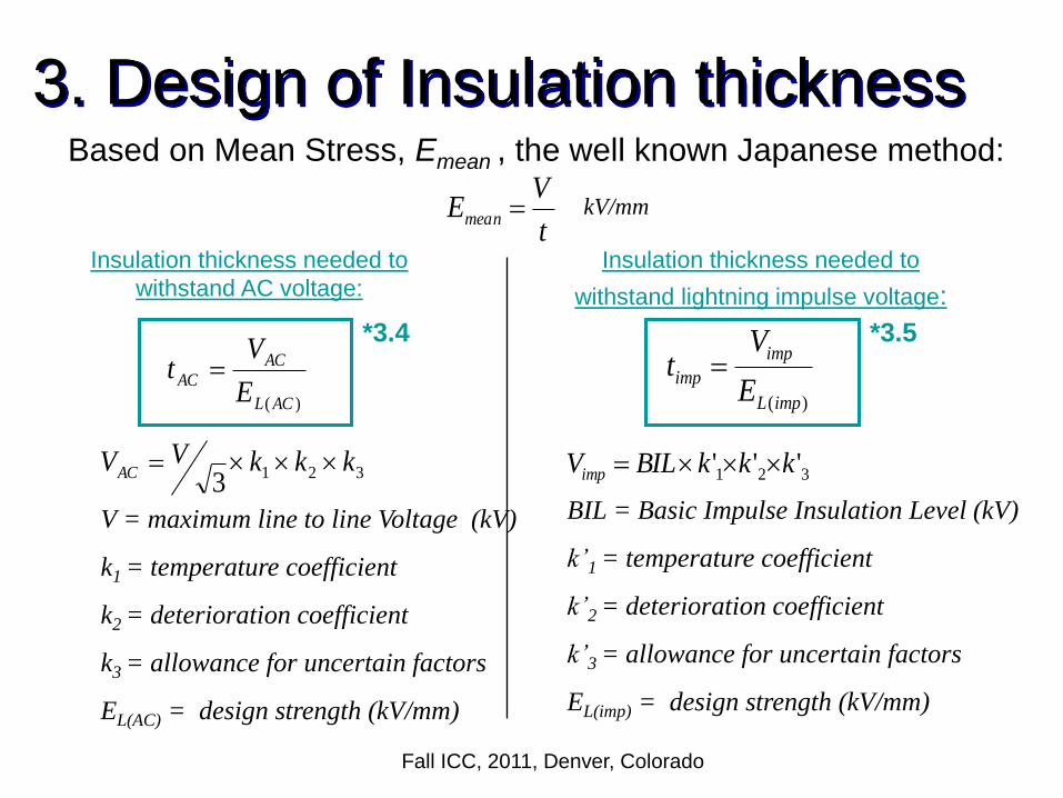
t
VEmean
Based on Mean Stress, Emean , the well known Japanese method:
Insulation thickness needed to
withstand AC voltage:
)( ACL
AC
ACE
Vt
)(impL
imp
impE
Vt
3213
kkkVVAC
V = maximum line to line Voltage (kV)
k1 = temperature coefficient
k2 = deterioration coefficient
k3 = allowance for uncertain factors
EL(AC) = design strength (kV/mm)
kV/mm
Insulation thickness needed to
withstand lightning impulse voltage:
321 ''' kkkBILVimp
BIL = Basic Impulse Insulation Level (kV)
k’1 = temperature coefficient
k’2 = deterioration coefficient
k’3 = allowance for uncertain factors
EL(imp) = design strength (kV/mm)
3. Design of Insulation thickness
*3.4 *3.5
Fall ICC, 2011, Denver, Colorado
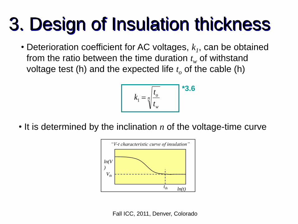
• Deterioration coefficient for AC voltages, k1, can be obtained
from the ratio between the time duration tw of withstand
voltage test (h) and the expected life to of the cable (h)
ln(V
)
ln(t)
Vth
tth
“V-t characteristic curve of insulation”
n
w
o
t
tk 1
• It is determined by the inclination n of the voltage-time curve
3. Design of Insulation thickness
*3.6

Fall ICC, 2011, Denver, Colorado
• Temperature coefficient, k2, can be obtained from the ratio
between breakdown strength at room temperature to the
breakdown strength at 90°C
• k3 gives allowance for unknown factors
• Values of k2 = 1.1 and k3 = 1.1 are commonly adopted
• For a reasonable value of n = 12 for XLPE cables, an
expected cable life of 30 years and a one-hour withstand
voltage test:
83.21
243653012
1
k
3. Design of Insulation thickness

Fall ICC, 2011, Denver, Colorado
• EL(AC) and EL(imp) can be obtained from cable insulation
breakdown data which confirm to a Weibull distribution as
shown:
bE
EE
o
L
eEF
1)(
F(E) = Probability of breakdown occuring before stress E
EL = Location parameter
Eo = Scale parameter
b = Shape parameter
3. Design of Insulation thickness
*3.7

Fall ICC, 2011, Denver, Colorado
3. Design of Insulation thickness • Example of test data plotted on Weibull distribution paper:

Fall ICC, 2011, Denver, Colorado
4 How to prove the correct
design ?

Fall ICC, 2011, Denver, Colorado
Experience with HV extruded cables
The evolution of XLPE MV and HV systems commenced in the 1960s. In the 1970s, the first commercial 90-132-154 kV XLPE systems were installed in Europe and in Japan .
CIGRE WG 21.10 has published in Electra 137 a survey on the service performance on HV AC cable systems. The failure rate of extruded cable systems was very low (0.1 failures per 100 circuit km per year on cables and accessories - external failures were not included).
There are a number of designs of joints and terminations currently in use. At voltages up to and including 150 kV extruded insulation has largely
superseded paper-insulated cables for new installations Much of the ‘good’ experience with HV XLPE cable systems is based on
older cable construction with moderate design stresses.
.
Hence historical service experience with HV cable systems is not necessarily a good guide for the design of future systems. International Tests requirements were necessary.

Fall ICC, 2011, Denver, Colorado
How to prove the correct design ?
• IEC test requirements have evolved over the years from the component based approach in IEC 840 to the system based approach, where accessories are considered together with the cable, in IEC 62067 and the most recent edition of IEC 60840.
• The IEC has published series of test specifications for HV and EHV cables, accessories and cable systems:
• In 1988, the first specification was published. IEC 840 (renamed later as IEC 60840) is for cables up to 150 kV (Um=170 kV). In this specification, type tests, routine and sample tests were prescribed for cables only.

Fall ICC, 2011, Denver, Colorado
How to prove the correct design ?
• In 1999 IEC revised this specification and
IEC 60840 Ed2 was published, in which
accessories were included in type testing .
• In 2004 IEC published a third edition, IEC
60840 Ed3, in which type tests on cable
system and routine and sample tests on
prefabricated accessories were introduced

Fall ICC, 2011, Denver, Colorado
How to prove the correct design ?
• As cable makers started to develop EHV XLPE cable systems, they needed testing programmes both to monitor their own progress and to give customers confidence in the products being developed.
• Initially, these testing programmes were agreed on a local or national basis. – For example, France used a 250-cycles test for 6000 hours at
U0, (this test was also performed on HV cables)
– Belgium adopted a 100-cycles test at 2U0.
– Japan used a half-year test at relatively low electrical stress based on the degradation factor of the insulation system.

Fall ICC, 2011, Denver, Colorado
Service experience with EHV extruded cable
systems before publication of international Standard
Late 1970s: First 220-275 kV XLPE systems installed
1980s: Start-up of widespread commercial use of XLPE cables up to
230 kV 1989: The first 275 kV XLPE systems with joints installed in Japan .
Qualification using Japanese utility specifications
1969: In France first installation of 225 kV low-density polyethylene
(LDPE) cable, followed by more than 1000 km of LDPE cable with field-
moulded joints and around 600 km of high-density polyethylene (HDPE)
cables with good service experience.
1985: in France first installation of 400 kV LDPE cables. In total, 40
km of cable and 21 back-to-back joints have been installed.
1999: in France first installation of 400 kV XLPE cable
1988: Commissioning in Japan of the world’s first 500 kV XLPE
system followed by two subsequent circuits in 1988 and 1991 (short
circuits without joints) .

Fall ICC, 2011, Denver, Colorado
How to prove the correct design ?
• Plans to install major 400 kV cable systems (Berlin, Copenhagen) led CIGRE to set up a Working Group to consider an international test specification. The tests were developed to give confidence that cable system passing the tests would have a fault rate in service lower than 0.2 faults/100km/year.
• In 1993 CIGRE WG 21-03 published a test program for cable systems above 150 (170) kV and IEC published a specification based on these documents IEC 62067 in late 2001.

Fall ICC, 2011, Denver, Colorado
Preamble of the 2001 Standard
• Such cables form part of the backbone of the
transmission system and therefore, reliability
considerations are of the highest priority ;
• These cables and their accessories operate with higher
electrical stresses than cables up to 150 kV and, as a
result, have a smaller safety margin with respect to the
intrinsic performance boundaries of the cable system;
• Such cables and accessories have a thicker insulation
wall than those up to 150 kV and, as a result, are
subjected to greater thermomechanical effects ;
• The design and coordination of the cables and
accessories becomes more difficult with increasing
system voltages

Fall ICC, 2011, Denver, Colorado
Background of CIGRE input
• While the type, special and routine test which are specified have been adequate at voltages up to 150 kV, and indeed operating experiences have proven this, they are not adequate on their own to cover the extension to higher voltage cables.
• It is considered that in order to gain some indication of the long term reliability of the proposed cable system, it is necessary to carry out a long term accelerated ageing test.
• The test should be performed on the complete cable system comprising cable, joints and terminations.
• The concept of performing such a test is well established in many countries
The test shall be called a prequalification test. This test is to be performed only once

Fall ICC, 2011, Denver, Colorado
Prequalification Test as per IEC
62067
As it could have been difficult to understand what is a substantial change, on request
from IEC, CIGRE WG B1.06 has issued recommendations on how to handle changes.
These recommendations are published in CIGRE Technical Brochure TB 303.
Electrical Stresses are the basis of these recommendations

Fall ICC, 2011, Denver, Colorado
Prequalification Test
• The prequalification test shall comprise the electrical tests on the complete cable system with approximately 100 m of full sized cable including accessories. The normal sequence of tests shall be:
a) heating cycle voltage test;
b) lightning impulse voltage test on cable samples
c) examination of the cable system after completion of the tests above.
• NOTE - The prequalification test may be omitted if an alternative long term test has been carried out and satisfactory service experience can be demonstrated.

Fall ICC, 2011, Denver, Colorado
Pre-qualification test
• The pre-qualification test shall
comprise the electrical tests on the
complete cable system with
approximately 100m of full sized
cable including accessories. One
year at 1.7 Uo with 180 heat cycles

Fall ICC, 2011, Denver, Colorado
Range of approval PQ
• This Long Term Testing has been introduced as a "prequalification test PQ", which is described in paragraph 13 of IEC 62067.
• As indicated in paragraph 13.1, this test "qualifies the manufacturer as a supplier of cable systems with the same or lower voltage ratings as long as the calculated electrical stresses at the insulation screen are equal to or lower than for the cable system tested.
• Note: It is recommended to carry out a prequalification test using cable of a large conductor cross section in order to cover thermo mechanical aspects.”

Fall ICC, 2011, Denver, Colorado
Type Tests
Tests made before supplying on a general commercial basis a type of cable system, in order to demonstrate satisfactory performance characteristics to meet the intended application. Once successfully completed, these tests need not be repeated, unless changes are made in the cable or accessory materials, or design or manufacturing process which might change the performance characteristics.

Fall ICC, 2011, Denver, Colorado
Type Tests
Bending test on the cable
Partial discharge test at ambient temperature
Tang measurement
Heating cycle voltage test
Switching impulse voltage test
Lightning impulse voltage test
Partial discharge tests
- at ambient temperature and
- at high temperature
Test of outer protection for buried joint

Fall ICC, 2011, Denver, Colorado
Range of approval TT
In § 12.2 of IEC 62067 - 2001 Range of type approval, it is stated that :
"When the type tests have been successfully performed on one cable system of specific cross section, rated voltage and construction, the type approval shall be accepted as valid for cable systems within the scope of this standard with other cross-sections, rated voltages and constructions if the following conditions are all met :
• The voltage group is not higher than that of the tested cable system;
• The conductor cross-section is not larger than that of the tested cable;
• The cable and the accessories have the same or a similar construction as that of the tested cable system;
• Calculated maximum electrical stresses on the conductor and insulation screens, in the main insulation part of the accessory and in boundaries are equal to or lower than for the tested cable and accessory.

50
Electrical Stresses (or fields)
• Electrical field on the
conductor:
– to establish the lifetime curve
of the extruded insulation
– to determine the B.I.L
performance
• Electrical field over
insulation:
– to determine the interface
between cable and accessory

Fall ICC, 2011, Denver, Colorado
Large
400 kV projects
Following
recommendations of
CIGRE or IEC 62067
Project CableCablelength(km)
Conductor
ElectricalstressesIN/OUT(kV/mm)
Metallicscreen
Outersheath
Joints TerminationsInstallation
type
A 35 1600 mm2
Cu
5 segments
11.5/5.4 Cu wires
Al laminatedsheath
PE withflame
retardantvarnish
39 compositepre-fabricated
12 GIS Tunnel +forced
ventilation
B 16 1600 mm2
Cu
5 segments
12.5/6.2 Cu wires
Al laminatedsheath
PE withflame
retardantvarnish
15premouldedone piece
6 GIS Tunnel +forced
ventilation
Berlin
C 19 1600 mm2
Cu
6 segments
12.5/6.2 Corrugated Al PE withflame
retardantvarnish
24premouldedone piece
6 GIS Tunnel +forced
ventilation
Copenhagen 104 1600 mm2
Cukeystone
11.5/4,9 ExtrudedLead
PE withsemi
conductinglayer
72 compositepre-fabricated
42premouldedone piece
24 GIS
12 outdoorporcelain
Directburied
(concrete &weak mix)
A 39 2500 mm2
Cu
6 segments
11.6/6.5 Cu wires
Al laminatedsheath
PE withflame
retardantlayer
48 compositepre-fabricated
6 outdoorporcelain
Tunnel +forced
ventilation
Madrid
B 39 2500 mm2
Cu
6 segments
12.5/7.2 Al Weldedlaminated
sheath
PE flameretardant
48premouldedone piece
6 outdoorporcelain
Tunnel +forced
ventilation
London 60 2500 mm2
Cu
6 segments
11.6/6.5 Cu wires
Al laminatedsheath
PE withflame
retardantlayer
60 compositepre-fabricated
6 GIS Tunnel +forced
ventilation
Jutland 84 1200 mm2
Al stranded12.6/6 Al wires
Al laminatedsheath
PE withsemi
conductinglayer
96premouldedone piece
36 outdoorcomposite
Directburied and
ducts

Fall ICC, 2011, Denver, Colorado
5 How to control the
quality of the
manufacturing?

Fall ICC, 2011, Denver, Colorado
How to control the quality of the manufacturing?
Through routine tests and sample tests
Routine tests
• Tests made by the manufacturer on all manufactured components (length of cable or accessory) to check that the component meets the specified requirements.
Sample tests
• Tests made by the manufacturer on samples of complete cable or components taken from a complete cable or accessory, at a specified frequency, so as to verify that the finished product meets the specified requirements.

Fall ICC, 2011, Denver, Colorado
Routine Test
The following tests shall be carried out on each manufactured length of cable and on the main insulation of each prefabricated accessory, to check that the whole of each length and that the main insulation of each prefabricated accessory complies with the requirements.
a) partial discharge test ;
b) voltage test ;
c) electrical test on oversheath of the cable, if required .

Fall ICC, 2011, Denver, Colorado
Partial Discharge/Voltage Test
• The voltage test shall be made at ambient
temperature using an alternating test voltage at
power frequency.
• The test voltage shall be raised gradually to the
specified value which shall then be held for the
specified time between the conductor and
metallic screen/sheath according to specified
value
• No breakdown of the insulation shall occur.

Fall ICC, 2011, Denver, Colorado
Sample Tests
The following tests shall be carried out on samples which, for the tests in items b) and g), may be complete drum lengths of cable, taken to represent batches.
a) conductor examination ;
b) measurement of electrical resistance of conductor ;
c) measurement of thickness of insulation and oversheath;
d) measurement of thickness of metallic sheath (see 10.7);
e) measurement of diameters, if required;
f) hot set test for XLPE and EPR insulations;
g) measurement of capacitance;
h) measurement of density of HDPE insulation;
i)lightning impulse voltage test followed by a power frequency voltage test;
j) water penetration test, if required.

Fall ICC, 2011, Denver, Colorado
Sample Tests: frequency
• The sample tests in items a) to h) shall be carried out on one length from each batch of the same type and cross-section of cable, but shall be limited to not more than 10 % of the number of lengths in any contract, rounded to the nearest whole number.
• The frequency of the tests in items i) and j) shall be at the discretion of the manufacturer but shall at least comply with the following:
Size of the order – above 4 km and up to and including 20 km: I sample
– above 20 km : 2 samples

Fall ICC, 2011, Denver, Colorado
Routine and Sample Tests
Faraday cage and Transformer for Routine Testing

Fall ICC, 2011, Denver, Colorado
Equipment for Sample Testing
Sample testing cable+accessories of a 400 kV cable system

Fall ICC, 2011, Denver, Colorado
6 How to check the
quality of the installation
of accessories?

Fall ICC, 2011, Denver, Colorado
Commissioning tests
• Proving the wiring that provides remote control, signalling and
measurement equipment.
• Tests for correct operation of remote control, signalling and
measurement equipment.
• Checking the electrical clearances and conductor sag for the
jumpers
• When use of DTS, taking the initial Route Temperature Profile of the
system
• Tests after installation of underground sections
• test of the oversheath
• electrical test of the main insulation

Fall ICC, 2011, Denver, Colorado
Electrical Tests After Installation
Tests on new installations are carried out when the
installation of the cable and its accessories has
been completed.
An oversheath test and/or an a.c. insulation test
is recommended. For installations where the
oversheath test is carried out, quality assurance
procedures during installation of accessories
may, by agreement between the purchaser and
contractor, replace the insulation test.

Fall ICC, 2011, Denver, Colorado
Electrical Tests after Installation
DC voltage test of the oversheath
The voltage level and duration specified in clause 5 of IEC 60229 shall be applied between each metal sheath or concentric wires or tapes and the ground. For the test to be effective, it is necessary that the ground makes good contact with all of the outer surface of the oversheath. A conductive layer on the oversheath can assist in this respect.
AC voltage test of the insulation
The a.c. test voltage (20 Hz to 300 Hz) to be applied shall be subject to agreement between the purchaser and the contractor. The waveform shall be substantially sinusoidal. The voltage shall be applied for 1 h, either with a voltage according to table 10 or with 1,7 U0, depending on practical operational conditions.
Alternatively, a voltage of U0 may be applied for 24 h.

Fall ICC, 2011, Denver, Colorado
Tests of the underground section
(ref: Electra 173,1997 by WG 21-
09/2 and IEC 62067
– 24 Hours at Uo
– Higher test voltages
from 1.1 to 1.7 Uo with
dedicated equipment
• access in the vicinity
of termination
• distances between
live parts and
surrounding
equipment

Fall ICC, 2011, Denver, Colorado
Electrical tests on HV/EHV cable circuits

Fall ICC, 2011, Denver, Colorado
Electrical Tests

Fall ICC, 2011, Denver, Colorado
7 Some Special Purpose
Tests

Fall ICC, 2011, Denver, Colorado
Some Special Purpose Tests
Corrosion test on laminate coverings
Short Circuit Test

Fall ICC, 2011, Denver, Colorado
8 Extension of
qualification Tests
Fall ICC, 2011, Denver, Colorado
Extension of qualification
• This item will be addressed in a further
Educational Session

Fall ICC, 2011, Denver, Colorado
Thank You for your attention
Questions?