cenelec - dxdlw.com02\26\1324331871\德国hd 603 s1-a2... · iec 60183 guide of the selection of...
TRANSCRIPT
HARMONIZATION DOCUMENT HD 603 S1/A2
DOCUMENT D'HARMONISATION
HARMONISIERUNGSDOKUMENT June 2003
CENELEC European Committee for Electrotechnical Standardization
Comité Européen de Normalisation Electrotechnique Europäisches Komitee für Elektrotechnische Normung
Central Secretariat: rue de Stassart 35, B - 1050 Brussels
© 2003 CENELEC - All rights of exploitation in any form and by any means reserved worldwide for CENELEC members.
Ref. No. HD 603 S1:1994/A2:2003 E
ICS 29.060.20
English version
Distribution cables of rated voltage 0,6/1 kV Câbles de distribution de tension nominale 0,6/1 kV
Energieverteilungskabel mit Nennspannungen 0,6/1 kV
This amendment A2 modifies the Harmonization Document HD 603 S1:1994; it was approved by CENELEC on 2003-02-01. CENELEC members are bound to comply with the CEN/CENELEC Internal Regulations which stipulate the conditions for implementation of this amendment on a national level. Up-to-date lists and bibliographical references concerning such national implementation may be obtained on application to the Central Secretariat or to any CENELEC member. This amendment exists in one official version (English). CENELEC members are the national electrotechnical committees of Austria, Belgium, Czech Republic, Denmark, Finland, France, Germany, Greece, Hungary, Iceland, Ireland, Italy, Luxembourg, Malta, Netherlands, Norway, Portugal, Slovakia, Spain, Sweden, Switzerland and United Kingdom.

Page 0-2 HD 603 S1:1994/A2:2003
Foreword
This amendment to the Harmonization Document HD 603 S1:1994 was prepared by WG9 of Technical Committee CENELEC TC 20, Electric cables. The Technical Committee CENELEC TC 20 confirmed at its Lucerne meeting (May 2000) that the amendment should go to the Unique Acceptance Procedure. As well as the listed additions and amendments to the particular sections of Parts 3-8, the whole of Part 1 has been re-issued, especially to the extensive changes to cross-references. Users of HD 603 should note that, in the particular sections, cross-references have only been updated where the complete section has been re-issued. This Part 0 of HD 603 contains a list of relevant changes to cross-references, which should be consulted in conjunction with the particular section. National standards implementing one or more particular sections of HD 603 may update cross-references in advance of changes to the published version of the HD. By decision of the Technical Board (D81/139 extended by D104/118 & D114/076) this HD exists only in English. The text of the draft was submitted to the Unique Acceptance Procedure and was approved by CENELEC as amendment A2 to HD 603 S1:1994 on 2003-02-01. The following dates were fixed: - latest date by which the existence of the amendment has
to be announced at national level (doa) 2003-08-01 - latest date by which the amendment has to be implemented at national
level by publication of an harmonized national standard or by endorsement (dop) 2004-02-01
- latest date by which the national standards conflicting with the
amendment have to be withdrawn (dow) 2006-02-01 __________

Page 0-3 HD 603 S1:1994/A2:2003
CONTENTS
(HD 603 S1:1994 plus A1 and A2)
Part 1 1) 5) GENERAL REQUIREMENTS Part 3 PVC INSULATED CABLES - UNARMOURED 3A 1) Cables with (type 3A-1) and without (type 3A-2) concentric conductor
3B Cables without concentric conductor (type 3B-1)
3C Cables (type 3C-1) with concentric conductor, PVC sheath
3D Cables (type 3D-1) without concentric conductor, PE sheath
3E Cables (type 3E-1) without concentric conductor, PVC sheath
3F 1) 4) Cables with (type 3F-1)and without (type 3F-2)concentric conductor
3G 1) 5) Cables with (type 3G-1) and without (type 3G-2) concentric conductor
3H Cables with (type 3H-1)and without (type 3H-2) concentric conductor
3I 1) 5) Cables with (type 3I-1) and without (types 3I-2 and 3I-3) concentric conductor
3J 1) Cables with concentric conductor (type 3J-1)
3K 6) Cables without concentric conductor (type 3K-1)
3L 1) 5) Cables with concentric conductor (type 3L-1)
3M 2) Unarmoured cables (type 3M-1)
3N 5) Unarmoured cables (type 3N)
3O Cables without (type 3O-1) concentric conductor
Part 4 PVC INSULATED CABLES - ARMOURED 4A 1) Cables with concentric conductor (screen) (type 4A)
4B 1) 5) Cables with braided (type 4B-1) or helically applied (type 4B-2) armour
4C 2) Cables without concentric conductor (type 4C)
4D (1) Armoured cables without (type 4D-1) concentric conductor
Part 5 XLPE INSULATED CABLES - UNARMOURED 5A Cables without concentric conductor (type 5A)
5B Cables (type 5B) without concentric conductor, PE sheath
5C Cables (type 5C) without concentric conductor, PVC sheath
5D 1) 4) Cables with and without concentric conductor (types 5D-1 and 5D-2)
5E 1) Cables (for energy boards) with concentric conductor (type 5E)
5F 1) Cables with concentric screen and uninsulated neutral (type 5F)
5G 1) 5) Cables with (type 5G-1) and without (type 5G-2) concentric conductor
5H Cables without concentric conductor (type 5H)
5I 1) 5) Cables without concentric conductor (type 5I)
5J 1) Cables with concentric conductor (type 5J)
5K 1) Cables with concentric screen (type 5K)
5L 1) Cables with concentric screen (type 5L)

Page 0-4 HD 603 S1:1994/A2:2003 5M 1) Cables without concentric conductor (type 5M)
5N 1) Cables without concentric conductor (type 5N)
5O 5) Cables without concentric conductor, PVC sheath (type 5O)
5P 1) 5) Cables with concentric conductor, PVC or PE sheath (type 5P-1 and 5P-2)
5Q 1) 7) CNE cables with solid neutral/earth conductor (type 5Q)
5R 1) 5) CNE cables with concentric waveform neutral/earth conductor (type 5R)
5S 1) 5) Service cables with concentric conductor (type 5S)
5T 1) Cables with (type 5T-1) and without (type 5T-2) concentric conductor
5U Cables with (type 5T-1) concentric waveform neutral conductor
5V 3) Unarmoured cables (type 5V)
5W 3) Cables with concentric conductor (type 5W)
Part 6 XLPE INSULATED CABLES - ARMOURED 6A 1) 5) Cables with braided (type 6A-1) or helically applied (type 6A-2) armour
6B 6) Cables without concentric conductor (type 6B)
6C 1) Armoured cables with (type 6C-1) and without (type 6C-2) concentric conductor
6D 3) Steel tape armoured cables (type 6D)
Part 7 EPR INSULATED CABLES - UNARMOURED 7A 5) Cables with and without concentric conductor (type 7A)
7B 5) Pre-assembled cables without concentric conductor (type 7B)
7C 1) Cables without concentric conductor (type 7C)
7D 1) 7) Cables with concentric waveform neutral/earth conductor (type 7D)
7E 1) Cables with (type 7E-1) and without (type 7E-2) concentric conductor
Part 8 EPR INSULATED CABLES - ARMOURED 8A 6) Cables without concentric conductor (type 8A)
8B 1) Armoured cables with (type 8B-1) and without (type 8B-2) concentric conductor
NOTES 1) Amendment A1 introduces some changes to the text. 2) Amendment A1 completely revises the particular section. 3) New section introduced by amendment A1. 4) Amendment A2 introduces some changes to the text. 5) Amendment A2 completely revises the particular section. 6) Amendment A1 withdraws the section. 7) Amendment A2 withdraws the section.

Page 0-5 HD 603 S1:1994/A2:2003
List of updated cross-references
Original Ref Original title New Ref New title
HD 186 Marking by inscription for the identification of cores of electric cables having more than five cores
EN 50334 Marking by inscription for the identification of cores of electric cables
HD 405 (series) Test on electric cables under fire condition
EN 50265 (series) Common test methods for cables under fire conditions Test for resistance to vertical flame propagation for a single insulated conductor or cable.
HD 405.1 Tests on electric cables under fire conditions Part 1: Test on a single vertical insulated wire or cable
EN 50265-2-1 Common test methods for cables under fire conditions Test for resistance to vertical flame propagation for a single insulated conductor or cable Part 2-1: Procedure 1 kW pre-mixed flame
HD 405.3 Tests on electric cables under fire conditions Part 3: Tests on bunched wires or cables
EN 50266 (series) Common test methods for cables under fire conditions Test for vertical flame spread of vertically-mounted bunched wires or cables
HD 505 (series) Common test methods for insulating and sheathing materials of electric cables
EN 60811 (series) Insulating and sheathing materials of electric cables Common test methods
HD 606 (series) Measurement of smoke density of electric cables burning under defined conditions
EN 50268 (series) Common test methods for cables under fire conditions Measurement of smoke density of cables burning under defined conditions
IEC 183 Guide to the selection of high-voltage cables
IEC 60183 Guide of the selection of high-voltage cables
IEC 60502 Extruded solid dielectric insulated power cables for rated voltages from 1 kV to 30 kV
IEC 60502-1 Power cables with extruded insulation and their accessories for rated voltages from 1 kV (Um = 1,2 kV) up to 30 kV (Um = 36 kV) Part 1: Cables for rated voltages of 1 kV (Um = 1,2 kV) and 3 kV (Um = 3,6 kV)
IEC 754-1 Tests on gases evolved during combustion of materials from cables Part 1: Determination of the amount of halogen acid gas
EN 50267-2-1 Common test methods for cables under fire conditions Tests on gases evolved during combustion of materials from cables Part 2-1: Procedures Determination of the amount of halogen acid gas

Page 0-6 HD 603 S1:1994/A2:2003
BLANK PAGE

Page 1-0 HD 603 S1:1994/A2:2003
Part 1
PART 1: GENERAL REQUIREMENTS
Replace the complete part by the following:


Page 1-1 HD 603 S1:1994/A2:2003
Part 1
HD 603 S1:1994/A2:2003
DISTRIBUTION CABLES OF RATED VOLTAGE 0,6/1 KV
PART 1: GENERAL REQUIREMENTS

Page 1-2 HD 603 S1:1994/A2:2003 Part 1
CONTENTS General..........................................................................................................................................................4
1.1 Scope ....................................................................................................................................4
1.2 Object....................................................................................................................................4
2 Definitions ..............................................................................................................................................4
2.1 Definitions concerning the insulating and sheathing compounds .........................................4
2.2 Definitions relating to the tests ..............................................................................................5
2.3 Rated voltage ........................................................................................................................6
3 Marking...................................................................................................................................................6
3.1 Indication of origin .................................................................................................................6
3.2 Additional marking.................................................................................................................7
3.3 Durability ...............................................................................................................................7
3.4 Legibility ................................................................................................................................7
3.5 Common marking..................................................................................................................7
3.6 Use of the name CENELEC..................................................................................................7
4 Core identification .................................................................................................................................7
5 General requirements for the construction of cables........................................................................8
5.1 Conductors............................................................................................................................8
5.2 Insulation...............................................................................................................................8
5.3 Assembly of conductors ........................................................................................................9
5.4 Fillers and tapes....................................................................................................................9
5.5 Inner covering (bedding) .......................................................................................................9
5.6 Innersheath .........................................................................................................................10
5.7 Metallic coverings................................................................................................................10
5.8 Oversheath..........................................................................................................................10
6 Tests on completed cables.................................................................................................................11
7 Sealing and packing............................................................................................................................11
8 Current ratings.....................................................................................................................................11
9 Guide to use and selection of cables ................................................................................................12
Page 1-3 HD 603 S1:1994/A2:2003
Part 1
REFERENCES
References are made in this Part 1 to other parts of HD 603 and to other Harmonization Documents as follows:
HD 383 Conductors of insulated cables First supplement: Guide to the dimensional limits of circular conductors (endorsing IEC 60228 and IEC 60228A)
HD 605 Electric cables Additional test methods
EN 50265 (series) Common test methods for cables under fire conditions Test for resistance to vertical flame propagation for a single insulated conductor or cable
EN 50334 Marking by inscription for the identification of cores of electric cables
EN 60811 (series) Insulating and sheathing materials of electric cables Common test methods
IEC 60287 (series) Electric cables Calculation of current rating In all cases reference to another HD or International Standard implies the latest edition of that document.

Page 1-4 HD 603 S1:1994/A2:2003 Part 1
1 General
1.1 Scope
HD 603 applies to cables of rated voltage Uo/U = 0,6/1 kV used in underground power distribution systems mainly for public distribution, of nominal voltage not exceeding 0,6/1 kV a.c.
This part (Part 1) specifies the general requirements applicable to these cables, unless otherwise specified in the particular sections of this HD.
Test methods are specified in HD 605 and in HD 383, EN 50265 and EN 60811.
The particular types of cables are specified in Parts 3 to 8.
1.2 Object
The objects of this Harmonization Document are:
− to standardise cables that are safe and reliable when properly used, in relation to the technical requirements of the system of which they form a part;
− to state the characteristics and manufacturing requirements which have a direct or indirect bearing on safety,
− and to specify methods for checking conformity with those requirements.
2 Definitions
2.1 Definitions concerning the insulating and sheathing compounds
2.1.1 Insulating and sheathing compounds
The types of insulating and sheathing compounds covered by this HD are listed below, together with their abbreviated designations:

Page 1-5 HD 603 S1:1994/A2:2003
Part 1
Table 2.1.1 Insulating and sheathing compounds
Insulating and sheathing compounds See: Insulation a) Thermoplastic: Insulating compounds based on: - polyvinyl chloride or copolymers (PVC) Table 1 - polyolefin (PO) Table 4C b) Cross-linked: Insulating compounds based on: - cross-linked polyethylene (XLPE) Table 2A - ethylene propylene rubber (EPR) Table 2B - hard ethylene propylene
rubber (HEPR) Table 2C
Sheathing a) Elastomeric Sheathing compound based on: - Polychloroprene (PCP) Table 3 - Chlorosulfonated polyethylene (CSP) or similar polymer b) Thermoplastic: Sheathing compounds based on: - polyvinyl chloride (PVC) Table 4A - polyethylene (PE) Table 4B - polyolefin (PO) Table 4C
2.1.2 Type of compound
The category in which a compound is placed according to its properties is determined by specific tests. The type designation is not directly related to the composition of the compound.
2.2 Definitions relating to the tests
NOTE Tests classified as sample (S) or routine (R) may be required as part of any type approval schemes.
2.2.1 Type tests (Symbol T)
Tests required to be made before supplying a type of cable covered by this HD on a general commercial basis in order to demonstrate satisfactory performance characteristics to meet the intended application. These tests are of such a nature that, after they have been made, they need not be repeated unless changes are made in the cable material, design or type of manufacturing process which might change the performance characteristics.
2.2.2 Sample tests (Symbol S)
Tests made on samples of completed cable, or components taken from a completed cable adequate to verify that the finished product meets the design specifications.
2.2.3 Routine tests (Symbol R)
Tests made on all production cable lengths to demonstrate compliance with requirements.
2.2.4 Tests after installation
Test intended to demonstrate the integrity of the cable and its accessories as installed.
Page 1-6 HD 603 S1:1994/A2:2003 Part 1 2.3 Rated voltage
The rated voltage of a cable is the reference voltage for which the cable is designed, and which serves to define the electrical tests.
The rated voltage is expressed by the combination of the following values Uo/U(Um) expressed in kV.
Uo is the rms. value between any insulated conductor and earth (metal covering of the cable or the surrounding medium); Uo = 0,6 kV
U is the rms. value between any two phase-conductors of a multicore cable or of a system of single-core cables; U = 1,0 kV
Um is the maximum rms. value of the highest system voltage for which the equipment may be used; Um = 1,2 kV.
In an alternating current system, the rated voltage of a cable shall be at least equal to the nominal voltage of the system for which it is intended.
If used in d.c. Systems, the cables of this HD shall have a maximum voltage against earth not exceeding 1,8 kV.
3 Marking
3.1 Indication of origin
Cables shall be provided with an identification of origin consisting of:
a) either the manufacturer's identification thread b) or the continuous marking of the manufacturer's name or trademark, or (if legally protected)
identification number by one of the three following alternative methods: a) printed tape within the cable, b) printing in a contrasting colour on the insulation of at least one core, c) printing, indenting or embossing on the outer surface of the cable.
3.1.1 Continuity of marks
Unless otherwise specified in the particular sections, each specified mark shall be regarded as continuous if the distance between the end of the mark and the beginning of the next identical mark does not exceed:
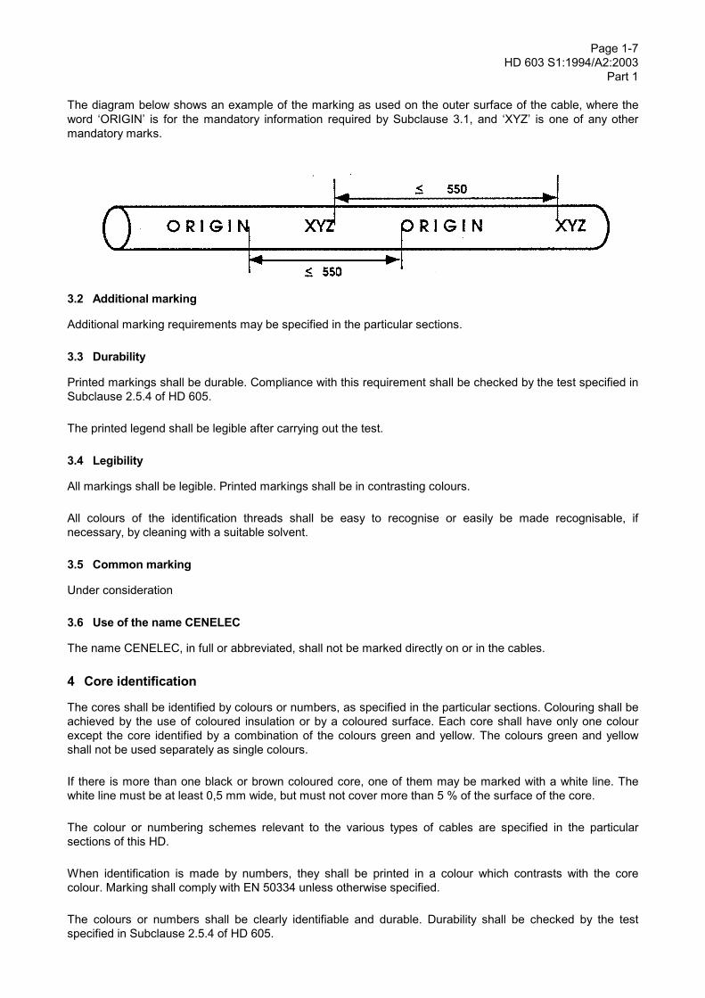
− 550 mm if the marking is on the outer surface of the cable,
− 275 mm if the marking is:
1) on the insulation of a sheathed cable,
2) on a tape within a sheathed cable.
NOTE A specified mark is any mandatory mark covered by this part of the HD or by the particular requirements of Part 3 onwards of this HD.
Page 1-7 HD 603 S1:1994/A2:2003
Part 1
The diagram below shows an example of the marking as used on the outer surface of the cable, where the word ORIGIN is for the mandatory information required by Subclause 3.1, and XYZ is one of any other mandatory marks.
3.2 Additional marking
Additional marking requirements may be specified in the particular sections.
3.3 Durability
Printed markings shall be durable. Compliance with this requirement shall be checked by the test specified in Subclause 2.5.4 of HD 605.
The printed legend shall be legible after carrying out the test.
3.4 Legibility
All markings shall be legible. Printed markings shall be in contrasting colours.
All colours of the identification threads shall be easy to recognise or easily be made recognisable, if necessary, by cleaning with a suitable solvent.
3.5 Common marking
Under consideration
3.6 Use of the name CENELEC
The name CENELEC, in full or abbreviated, shall not be marked directly on or in the cables.
4 Core identification
The cores shall be identified by colours or numbers, as specified in the particular sections. Colouring shall be achieved by the use of coloured insulation or by a coloured surface. Each core shall have only one colour except the core identified by a combination of the colours green and yellow. The colours green and yellow shall not be used separately as single colours.
If there is more than one black or brown coloured core, one of them may be marked with a white line. The white line must be at least 0,5 mm wide, but must not cover more than 5 % of the surface of the core.
The colour or numbering schemes relevant to the various types of cables are specified in the particular sections of this HD.
When identification is made by numbers, they shall be printed in a colour which contrasts with the core colour. Marking shall comply with EN 50334 unless otherwise specified.
The colours or numbers shall be clearly identifiable and durable. Durability shall be checked by the test specified in Subclause 2.5.4 of HD 605.

Page 1-8 HD 603 S1:1994/A2:2003 Part 1 The distribution of the colours for the core coloured green and yellow shall comply with the following condition: for every 15 mm length of core, one of these colours shall cover at least 30 % and not more than 70 % of the surface of the core, the other colour covering the remainder.
NOTE The colours green and yellow, when they are combined as specified above are recognised exclusively as a means of identification of the core intended for use as earth connection or similar protection.
Compliance with these requirements shall be verified by visual examination.
5 General requirements for the construction of cables
Compliance with the requirements specified in Subclauses 5.1 to 5.8 and in the particular sections of this HD shall be checked by inspection and by measurements according to the test methods listed in the particular sections.
5.1 Conductors
5.1.1 Material
Conductors shall be either plain or metal-coated annealed copper or plain aluminium or aluminium alloy in accordance with HD 383 and with particular requirements in particular sections of this HD.
Conductors shall be either circular or sector in shape, and of solid metal or stranded.
5.1.2 Electrical resistance
The resistance of each conductor at 20 ºC shall be in accordance with the requirements in HD 383 for the given class of conductor.
5.1.3 Separator tape
A separator tape may be placed between the conductor and insulation. Unless otherwise specified, it shall be non-hygroscopic.
It shall be easily removable from the conductor.
5.2 Insulation
5.2.1 Material
The insulation shall be an extruded solid compound of one of the types listed in Subclause 2.1.1 and as specified for each type of cable in the particular sections of this HD.
The test requirements for the insulating compounds are specified in Tables 1 and 2, and the reference to the test methods are specified in the particular sections.
The maximum conductor temperature in normal operation and the short-circuit temperature for each insulation are specified in the particular sections.
5.2.2 Application
The insulation may consist of one or more bonded layers. It shall be so applied that it fits closely on the conductor or over the separator tape, and it shall be possible to remove it without damage to the insulation itself, to the conductor or to the metal coating if any. The insulation shall be applied by a suitable extrusion process, cross-linked where required, and shall form a compact and homogeneous body.
5.2.3 Thickness
Unless otherwise specified in the particular sections, insulation thickness values are in Table 5 for each cable type and size.

Page 1-9 HD 603 S1:1994/A2:2003
Part 1
The mean value of the thickness of insulation shall be not less than the specified value.
However, the thickness at any place may be less than the specified value provided that the difference does not exceed 0,1 mm + 10 % of the specified value.
Compliance shall be checked by the test method specified in Subclause 2.1.1 of HD 605.
5.2.4 Mechanical properties before and after ageing
The insulation material shall have the characteristics specified in Tables 1 or 2 as appropriate.
5.2.5 Additional properties
These are specified in the particular sections.
5.3 Assembly of conductors
In multicore cables, the cores shall be cabled helically or with another suitable method.
Auxiliary cores, if any, shall be laid up in the interstices between main cores. Allowed number and requirements thereof are specified in the particular sections.
5.4 Fillers and tapes
For each type of cable, the particular sections detail whether that cable includes fillers or tapes, or whether the sheath or inner covering may penetrate between the cores, thus forming a filling.
A centre filler may be used in multicore cables, and the assembly of cores and fillers may be held together by a binder tape.
5.4.1 Material
The material used for fillers and binder tapes, if any, shall be suitable for the maximum conductor temperature in normal operation of the cable and compatible with the cable components with which they are in contact. The requirements and the reference to the test method are specified in the particular sections.
5.4.2 Application
Where fillers are used these may be applied either separately or as a part of the inner covering or the innersheath to form a compact and reasonably circular cable. It shall be possible to strip the fillers, if any, from the cable without damaging the insulation of cores.
5.5 Inner covering (bedding)
The inner covering, if any, may be extruded or lapped, or a combination of the two.
5.5.1 Material
The material used for inner coverings, if any, shall be suitable for the maximum conductor temperature in normal operation of the cable and compatible with the cable components with which it is in contact. The requirements and the reference to the test method are specified in the particular sections.
5.5.2 Application
The extruded inner covering shall surround the core assembly completely and may penetrate the spaces between them, giving the assembly a reasonably circular shape. The extruded inner covering shall be easily separable from the cores.

Page 1-10 HD 603 S1:1994/A2:2003 Part 1 Lapped bedding shall consist of one or more layers of tape covering the entire outer surface of the core assembly.
For each type of cable, the particular sections indicate whether that cable includes an extruded inner covering or a lapped bedding, or a combination of these.
5.5.3 Thickness
Unless otherwise specified for the particular type, the thickness of lapped bedding need not be checked by measurement.
The minimum thickness of extruded inner covering for each type and size of cable shall be as specified in the particular sections.
5.6 Innersheath
An innersheath may be specified in the particular sections.
5.6.1 Material
The material used for innersheath, if any, shall be suitable for the maximum conductor temperature in normal operation of the cable and compatible with the cable components with which it is in contact. The requirements and the reference to the test method are specified in the particular sections.
5.6.2 Application
The innersheath shall be extruded in a single layer. The sheath may be applied over an inner covering or directly over the core assembly. The sheath shall not adhere to the cores.
5.6.3 Thickness
The thickness of the extruded innersheath shall be as specified in the particular sections.
5.7 Metallic coverings
5.7.1 Type of metallic layers
The following types of metallic layers may be specified in particular sections:
a) metallic screen; b) concentric conductor; c) metallic armour; d) a combination of the aboveDetailed constructions of metallic coverings, together with the test
methods and requirements, are specified in the particular sections.
5.7.2 Application
The metallic covering may be applied over an inner covering or an innersheath or directly over the insulation.
5.8 Oversheath
5.8.1 Material
The oversheath shall be a compound suitable for the maximum conductor temperature in normal operation and of the type specified in the particular sections.
The test requirements for these compounds are specified in Tables 3 and 4 unless stated otherwise in the particular sections.

Page 1-11 HD 603 S1:1994/A2:2003
Part 1
5.8.2 Application
The oversheath shall be extruded and may consist of one or more layers.
For unarmoured cables the sheath shall not adhere to the cores. A separator, consisting of a film or tape, may be placed under the oversheath.
5.8.3 Thickness
Unless otherwise specified in the particular sections the following requirements shall apply.
5.8.3.1 Sheath applied over a smooth surface
For a sheath applied on a smooth cylindrical surface, such as an inner covering, a metal sheath or the insulation of a single-core, the mean value of the thickness of the oversheath shall be not less than the specified value for each type and size of cable in the particular sections.
However, the thickness at any place may be less than the specified value provided that the difference does not exceed 0,1 mm + 15 % of the specified value.
Test methods are specified in Subclause 2.1.2 of HD 605.
5.8.3.2 Sheath applied over an uneven surface
For a sheath applied on an irregular cylindrical surface, such as a penetrating sheath on an unarmoured cable without inner covering or a sheath applied directly over armour, metallic screen or concentric conductor, the smallest thickness at any point, of the oversheath shall not fall below the value specified in the appropriate particular sections by more than 0,2 mm + 20 % of the specified value.
Test methods are specified in Subclause 2.1.2 of HD 605.
5.8.4 Mechanical properties before and after ageing
The sheath material shall have the characteristics specified in Tables 3 or 4, as appropriate.
5.8.5 Additional properties
These are specified in the particular sections.
6 Tests on completed cables
All cables shall comply with the requirements specified in Subclauses 5.1 to 5.8 and in the particular sections of this HD and shall be checked by inspection and by measurements according to the test methods in documents listed in the particular sections.
7 Sealing and packing
Prior to storage or shipment, cable ends shall be sealed by appropriate measures so that water ingress is efficiently prevented.
Cables shall be packed as coils or on drums, according to the particular sections.
8 Current ratings
The current intensity that cables to this document can carry is determined by different conditions, either electrical (voltage drop) or thermal, whichever is most demanding.

Page 1-12 HD 603 S1:1994/A2:2003 Part 1 The maximum current ratings resulting from thermal limitations are calculated according IEC 60287 or equivalent existing methods.
These calculations shall take into account the actual installation and operating conditions.
Tabulated current rating values according to the cable type for typical installation conditions may be found in particular sections.
9 Guide to use and selection of cables
For guidance on the use of cables see particular sections of this HD.
When selecting the cables, attention is drawn to the fact that national conditions or regulations covering, e.g. climatic conditions or installation requirements, may exist. These should therefore be followed in conjunction of this HD.

Page 1-13 HD 603 S1:1994/A2:2003
Part 1
Table 1 Requirements of insulating compounds: PVC
1 2 3 4 5 6 7 8 9 10 11 12 13 14 15
Compound no. (spare) Unit DIV 1 DIV 2 DIV 4 DIV 5 DIV 6 DIV 7 DIV 8 DIV 9 DIV 10 DIV 11 DIV 12 DIV 13
Type PVC insulation
PVC insulation
PVC insulation
PVC insulation
PVC insulation
PVC insulation
PVC insulation
PVC insulation
PVC insulation
PVC insulation
PVC insulation lead free
PVC insulation
Maximum operating temperature of the conductor
ºC 70 70 70 70 70 70 70 70 70 70 70 70
Mechanical Properties
- before ageing on sample
minimum tensile strength MPa 12,5 12,5 12,5 12,5 12,5 12,5 12,5 12,5 12,5 12,5 12,5 12,5
minimum elongation at break % 125 150 175 125 150 150 150 125 150 150 150 125
- after ageing on sample
temperature ºC 80 100 100 80 100 100 100 90 100 100 100 80
duration T1 h 168 168 168 168 168 168 168 240 168 168 168 168
minimum tensile strength MPa 12,5 12,5 12,5 12,5 12,5 12,5 12,5 15 12,5 12,5 12,5 12,5
maximum variation T1/T0 % ± 20 ± 25 ± 20 ± 20 ± 25 ± 25 ± 25 ± 25 ± 25 ± 25 ± 25 ± 20
minimum elongation at break % 125 150 175 125 150 150 150 125 150 150 150 125
maximum variation T1/T0 % ± 20 ± 25 ± 20 ± 20 ± 25 ± 25 ± 25 ± 25 ± 25 ± 25 ± 25 ± 20
- after ageing on complete cable
(non contamination test)
temperature ºC 80 80 90 80 80 80 80 80 80 80 80 80
duration T1 h - - - - - - - - - - - -
duration T2 h 168 168 168 168 168 168 168 168 168 168 168 168
minimum tensile strength MPa - 12,5 12,5 12,5 12,5 12,5 - - - - - 12,5
maximum variation T2/T0 % ± 25 ± 25 ± 25 ± 20 ± 25 ± 25 ± 25 ± 25 ± 25 ± 25 ± 25 ± 20
maximum variation T2/T1 % - - - - - - - - - - - -
minimum elongation at break % - 150 175 125 150 150 150 125 150 150 150 125
maximum variation T2/T0 % ± 25 ± 25 ± 25 ± 20 ± 25 ± 25 ± 25 ± 25 ± 25 ± 25 ± 25 ± 20
maximum variation T2/T1 % - - - - - - - - - - -
Page 1-13H
D 603 S1:1994/A2:2003
Part 1
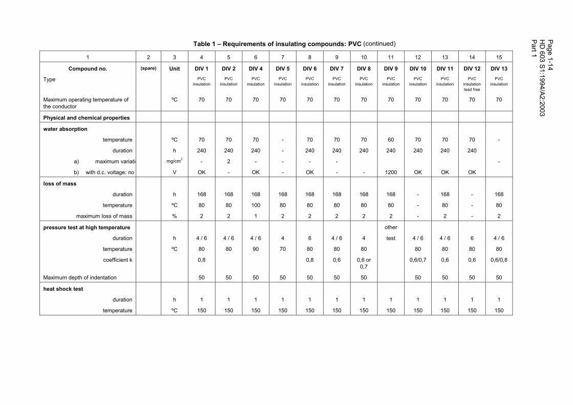
Table 1 Requirements of insulating compounds: PVC (continued)
1 2 3 4 5 6 7 8 9 10 11 12 13 14 15
Compound no. (spare) Unit DIV 1 DIV 2 DIV 4 DIV 5 DIV 6 DIV 7 DIV 8 DIV 9 DIV 10 DIV 11 DIV 12 DIV 13
Type PVC insulation
PVC insulation
PVC insulation
PVC insulation
PVC insulation
PVC insulation
PVC insulation
PVC insulation
PVC insulation
PVC insulation
PVC insulation lead free
PVC insulation
Maximum operating temperature of the conductor
ºC 70 70 70 70 70 70 70 70 70 70 70 70
Physical and chemical properties
water absorption
temperature ºC 70 70 70 - 70 70 70 60 70 70 70 -
duration h 240 240 240 - 240 240 240 240 240 240 240
a) maximum variatio mg/cm2 - 2 - - - - -
b) with d.c. voltage: no V OK - OK - OK - - 1200 OK OK OK
loss of mass
duration h 168 168 168 168 168 168 168 168 - 168 - 168
temperature ºC 80 80 100 80 80 80 80 80 - 80 - 80
maximum loss of mass % 2 2 1 2 2 2 2 2 - 2 - 2
pressure test at high temperature other
duration h 4 / 6 4 / 6 4 / 6 4 6 4 / 6 4 test 4 / 6 4 / 6 6 4 / 6
temperature ºC 80 80 90 70 80 80 80 80 80 80 80
coefficient k 0,8 0,8 0,6 0,6 or 0,7
0,6/0,7 0,6 0,6 0,6/0,8
Maximum depth of indentation 50 50 50 50 50 50 50 50 50 50 50
heat shock test
duration h 1 1 1 1 1 1 1 1 1 1 1 1
temperature ºC 150 150 150 150 150 150 150 150 150 150 150 150
Page 1-14 H
D 603 S1:1994/A2:2003
Part 1

Page 1-15 HD 603 S1:1994/A2:2003
Part 1
Table 1 Requirements of insulating compounds: PVC (concluded)
1 2 3 4 5 6 7 8 9 10 11 12 13 14 15
Compound no. Unit DIV 1 DIV 2 DIV 4 DIV 5 DIV 6 DIV 7 DIV 8 DIV 9 DIV 10 DIV 11 DIV 12 DIV 13
Type PVC insulation
PVC insulation
PVC insulation
PVC insulation
PVC insulation
PVC insulation
PVC insulation
PVC insulation
PVC insulation
PVC insulation
PVC insu lead free
PVC insulation
Maximum operating temperature of the conductor
ºC 70 70 70 70 70 70 70 70 70 70 70 70
Physical and chemical properties
tests at low temperature
elongation test at low temperature
temperature ºC - 15 - 15 - 20 - 15 - 25 - 15 - 15 - 15 - 15 - 20 - 15 - 15
minimum elongation % 20 20 40 20 20 20 20 20 20 20 20 20
impact test at low temp. on complete cable
temperature ºC - 15 - - - 15 - 20 - 15 - 15 - 25 - 15 - 20 - 15
bending test at low temperature
temperature ºC - 15 - 15 - 20 - 15 or - 20
- 25 - 15 - 15 - 15 - 15 - 20 - 15 - 15
thermal stability
temperature ºC 200 - 200 - - -
duration min 60 - 100 - - -
insulation resistance (minimum value)
volume resistivity at 20 ºC Ω.cm - 1013 - 1014 - 1013 1013 1013 -
at 60 ºC Ω.cm - - - 5.1010 - - -
at 70 ºC Ω.cm 1010 1010 1010 - 1010 1010 1010 1011 1010 1010 1010 1010
at 90 ºC Ω.cm - - - - - -
Insulation constant Ki at 70 ºC MΩ.cm
NOTE 1 MPa = 1 N/mm²
Remark: The tolerance on temperature values is given in HD 605, Subclause 1.5.2, but may be varied if specified in the particular sections.
Page 1-15H
D 603 S1:1994/A2:2003
Part 1

Table 2A Requirements of insulating compounds: XLPE
1 2 3 4 5 6 7 8 9 10
Compound no. (spare) Unit DIX 1 DIX 3 DIX 4 DIX 5 DIX 6 DIX 7 DIX 10
Type XLPE insulation
XLPE insulation
XLPE insulation
XLPE insulation
XLPE insulation
XLPE insulation
XLPE insulation
Maximum operating temperature of the conductor
ºC 90 90 90 90 90 90 90
Mechanical properties
- before ageing on sample
minimum tensile strength MPa 12,5 12,5 12,5 12,5 12,5 12,5 12,5
minimum elongation at break % 200 200 200 200 200 200 200
- after ageing on sample
temperature ºC 135 135 135 135 135 135 135
duration T1 h 168 168 168 168 168 168 168
minimum tensile strength MPa - - - 12,5 12,5 - -
maximum variation T1/T0 % ± 25 ± 25 ± 25 ± 25 ± 25 ± 25 ± 25
minimum elongation at break % - - - 200 200 - -
maximum variation T1/T0 % ± 25 ± 25 ± 25 ± 25 ± 25 ± 25 ± 25
- after ageing on complete cable
(non contamination test)
temperature ºC - 100 100 100 100 100 90
duration T1 h - - - - - 336 -
duration T2 h - 168 168 168 168 1008 168
minimum tensile strength MPa - - - 12,5 12,5 - -
maximum variation T2/T0 % - ± 25 ± 25 ± 25 ± 25 ± 40 ± 25
maximum variation T2/T1 % - - - - - ± 25 -
minimum elongation at break % - - - 200 200 - -
maximum variation T2/T0 % - ± 25 ± 25 ± 25 ± 25 ± 40 ± 25
maximum variation T2/T1 % - - - - - ± 25
Page 1-16 H
D 603 S1:1994/A2:2003
Part 1

Page 1-17 HD 603 S1:1994/A2:2003
Part 1
Table 2A Requirements of insulating compounds: XLPE (continued)
1 2 3 4 5 6 7 8 9 10
Compound no. (spare) Unit DIX 1 DIX 3 DIX 4 DIX 5 DIX 6 DIX 7 DIX 10
Type XLPE insulation
XLPE insulation
XLPE insulation
XLPE insulation
XLPE insulation
XLPE insulation
XLPE insulation
Maximum operating temperature of the conductor
ºC 90 90 90 90 90 90 90
Physical and chemical properties
hot set test
temperature ºC 150 200 200 200 200 200 200
duration min 15 15 15 15 15 15 15
mechanical stress MPa 0,2 or 0,4 0,2 0,2 0,2 0,2 0,2 0,2
maximum elongation under load % 200 175 175 175 175 100 175
maximum residual elongation % 25 15 15 15 15 15 15
water absorption
temperature ºC - 85 85 85 85 85 85
duration h - 336 336 336 336 336 336
a) maximum variation of mass Mg/cm² - 1/5 * 1 1 1 1 1
b) with d.c. voltage: no breakdown
Shrinkage test
duration h - 1 1 1 1 1 1
temperature ºC - 130 130 130 130 130 130
maximum shrinkage % - 4 4 4 4 4 4
* for density ≤ 1,02 g/ml: 1 for density > 1,02 g/ml: 5 NOTE 1 MPa = 1 N/mm² Remark: The tolerance on temperature values is given in HD 605, Subclause 1.5.2, but may be varied if specified in the particular sections. Page 1-17
HD
603 S1:1994/A2:2003Part 1
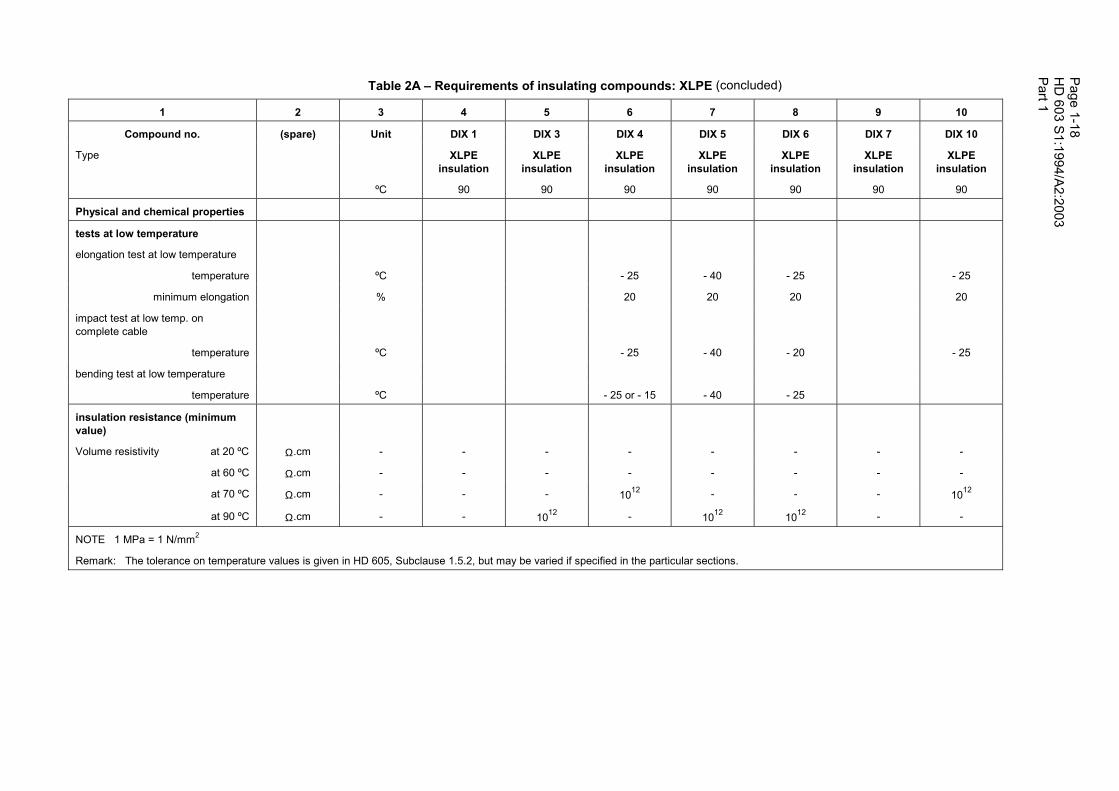
Table 2A Requirements of insulating compounds: XLPE (concluded)
1 2 3 4 5 6 7 8 9 10
Compound no. (spare) Unit DIX 1 DIX 3 DIX 4 DIX 5 DIX 6 DIX 7 DIX 10
Type XLPE insulation
XLPE insulation
XLPE insulation
XLPE insulation
XLPE insulation
XLPE insulation
XLPE insulation
ºC 90 90 90 90 90 90 90
Physical and chemical properties
tests at low temperature
elongation test at low temperature
temperature ºC - 25 - 40 - 25 - 25
minimum elongation % 20 20 20 20
impact test at low temp. on complete cable
temperature ºC - 25 - 40 - 20 - 25
bending test at low temperature
temperature ºC - 25 or - 15 - 40 - 25
insulation resistance (minimum value)
Volume resistivity at 20 ºC Ω.cm - - - - - - - -
at 60 ºC Ω.cm - - - - - - - -
at 70 ºC Ω.cm - - - 1012 - - - 1012
at 90 ºC Ω.cm - - 1012 - 1012 1012 - -
NOTE 1 MPa = 1 N/mm2
Remark: The tolerance on temperature values is given in HD 605, Subclause 1.5.2, but may be varied if specified in the particular sections.
Page 1-18 H
D 603 S1:1994/A2:2003
Part 1
Page 1-19 HD 603 S1:1994/A2:2003
Part 1
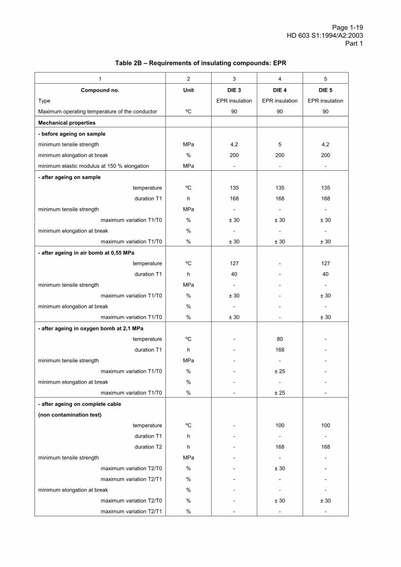
Table 2B Requirements of insulating compounds: EPR
1 2 3 4 5
Compound no. Unit DIE 3 DIE 4 DIE 5
Type EPR insulation EPR insulation EPR insulation
Maximum operating temperature of the conductor ºC 90 90 90
Mechanical properties
- before ageing on sample
minimum tensile strength MPa 4,2 5 4,2
minimum elongation at break % 200 200 200
minimum elastic modulus at 150 % elongation MPa - - -
- after ageing on sample
temperature ºC 135 135 135
duration T1 h 168 168 168
minimum tensile strength MPa - - -
maximum variation T1/T0 % ± 30 ± 30 ± 30
minimum elongation at break % - - -
maximum variation T1/T0 % ± 30 ± 30 ± 30
- after ageing in air bomb at 0,55 MPa
temperature ºC 127 - 127
duration T1 h 40 - 40
minimum tensile strength MPa - - -
maximum variation T1/T0 % ± 30 - ± 30
minimum elongation at break % - - -
maximum variation T1/T0 % ± 30 - ± 30
- after ageing in oxygen bomb at 2,1 MPa
temperature ºC - 80 -
duration T1 h - 168 -
minimum tensile strength MPa - - -
maximum variation T1/T0 % - ± 25 -
minimum elongation at break % - - -
maximum variation T1/T0 % - ± 25 -
- after ageing on complete cable
(non contamination test)
temperature ºC - 100 100
duration T1 h - - -
duration T2 h - 168 168
minimum tensile strength MPa - - -
maximum variation T2/T0 % - ± 30 -
maximum variation T2/T1 % - - -
minimum elongation at break % - - -
maximum variation T2/T0 % - ± 30 ± 30
maximum variation T2/T1 % - - -

Page 1-20 HD 603 S1:1994/A2:2003 Part 1
Table 2B Requirements of insulating compounds: EPR (concluded)
1 2 3 4 5
Compound no. Unit DIE 3 DIE 4 DIE 5
Type EPR insulation EPR insulation EPR insulation
Maximum operating temperature of the conductor ºC 90 90 90
Physical and chemical properties
hot set test
temperature ºC 250 250 250
duration min 15 15 15
mechanical stress MPa 0,2 0,2 0,2
maximum elongation under load % 175 175 175
maximum residual elongation % 15 15 15
hot modulus
duration min - 15 -
temperature ºC - 130 -
minimum strength at 100 % MPa - 1,75 -
water absorption
temperature ºC 85 70 85
duration h 336 336 336
a) maximum variation of mass mg/cm2 5 0,8 5
b) with d.c. voltage: no breakdown
insulation resistance Ki (minimum value)
at 20 ºC Ω.km - - -
at 60 ºC Ω.km - - -
at 70 ºC Ω.km - - -
at 90 ºC Ω.km - - 0,367
ozone resistance test
duration h 24 24 30
concentration of ozone % (250 to 300) 10-8 (250 to 300) 10-8 (250 to 300) 10-8
temperature ºC
NOTE 1 MPa = 1 N/mm2.
Remark: The tolerance on temperature values is given in HD 605, Subclause 1.5.2, but may be varied if specified in the particular sections.

Page 1-21 HD 603 S1:1994/A2:2003
Part 1
Table 2C Requirements of insulating compounds: HEPR
1 2 3 4 5
Compound no. Unit DIH 1 DIH 2 DIH 3
Type HEPR insulation
HEPR insulation
HEPR insulation
Maximum operating temperature of the conductor ºC 90 90 90
Mechanical properties
- before ageing on sample
minimum tensile strength MPa 8,5 8,5 8,5
minimum elongation at break % 200 200 200
minimum elastic modulus at 150 % elongation MPa 4,5 - -
- after ageing on sample
temperature ºC 150 135 135
duration T1 h 168 168 168
minimum tensile strength MPa - - -
maximum variation T1/T0 % ± 30 ± 30 ± 30
minimum elongation at break % - - -
maximum variation T1/T0 % ± 30 ± 30 ± 30
- after ageing in air bomb at 0,55 MPa
temperature ºC 127 127 127
duration T1 h 40 40 40
minimum tensile strength MPa - - -
maximum variation T1/T0 % ± 30 ± 30 ± 30
minimum elongation at break % - - -
maximum variation T1/T0 % ± 30 ± 30 ± 30
- after ageing on complete cable
(non contamination test)
temperature ºC 100 100 100
duration T1 h - - -
duration T2 h 168 168 168
minimum tensile strength MPa - - -
maximum variation T2/T0 % ± 30 ± 30 ± 30
maximum variation T2/T1 % - - -
minimum elongation at break % - - -
maximum variation T2/T0 % ± 30 ± 30 ± 30
maximum variation T2/T1 % - - -
Physical and chemical properties
hot set test
temperature ºC 250 250 250
duration min 15 15 15
mechanical stress MPa 0,2 0,2 0,2
maximum elongation under load % 100 100 100
maximum residual elongation % 10 15 25
Page 1-22 HD 603 S1:1994/A2:2003 Part 1
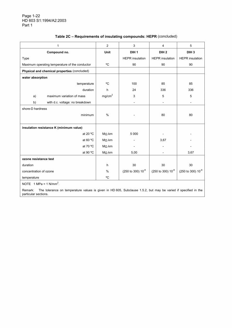
Table 2C Requirements of insulating compounds: HEPR (concluded)
1 2 3 4 5
Compound no. Unit DIH 1 DIH 2 DIH 3
Type HEPR insulation HEPR insulation HEPR insulation
Maximum operating temperature of the conductor ºC 90 90 90
Physical and chemical properties (concluded)
water absorption
temperature ºC 100 85 85
duration h 24 336 336
a) maximum variation of mass mg/cm2 3 5 5
b) with d.c. voltage: no breakdown - - -
shore-D hardness
minimum % - 80 80
insulation resistance K (minimum value)
at 20 ºC MΩ.km 5 000 - -
at 60 ºC MΩ.km - 3,67 -
at 70 ºC MΩ.km - - -
at 90 ºC MΩ.km 5,00 - 3,67
ozone resistance test
duration h 30 30 30
concentration of ozone % (250 to 300) 10-8 (250 to 300) 10-8 (250 to 300) 10-8
temperature ºC
NOTE 1 MPa = 1 N/mm2.
Remark: The tolerance on temperature values is given in HD 605, Subclause 1.5.2, but may be varied if specified in the particular sections.

Page 1-23 HD 603 S1:1994/A2:2003
Part 1
Table 3 Requirements of sheathing compounds: PCP
1 2 3
Compound no. Unit DMR 1
Type PCP sheath
Maximum operating temperature of the conductor ºC 90
Mechanical properties
- before ageing on sample
minimum tensile strength MPa 10
minimum elongation at break % 300
- after ageing on sample
temperature ºC 100
duration T1 h 168
minimum tensile strength MPa -
maximum variation T1/T0 % ± 30
minimum elongation at break % -
maximum variation T1/T0 % -
- after ageing in oil
temperature ºC 70
duration T1 h 4
minimum tensile strength MPa -
maximum variation T1/T0 % 80
minimum elongation at break % -
maximum variation T1/T0 % 80
Physical and chemical properties
hot set test
temperature ºC -
duration min -
mechanical stress MPa -
maximum elongation under load % -
maximum residual elongation % -
water absorption
temperature ºC 70
duration h 336
a) maximum variation of mass mg/cm2 4,65
b) with d.c. voltage: no breakdown
carbon black
minimum %
NOTE 1 MPa = 1 N/mm2.
Remark: The tolerance on temperature values is given in HD 605, Subclause 1.5.2, but may be varied if specified in the particular sections.
Page 1-24 HD 603 S1:1994/A2:2003 Part 1
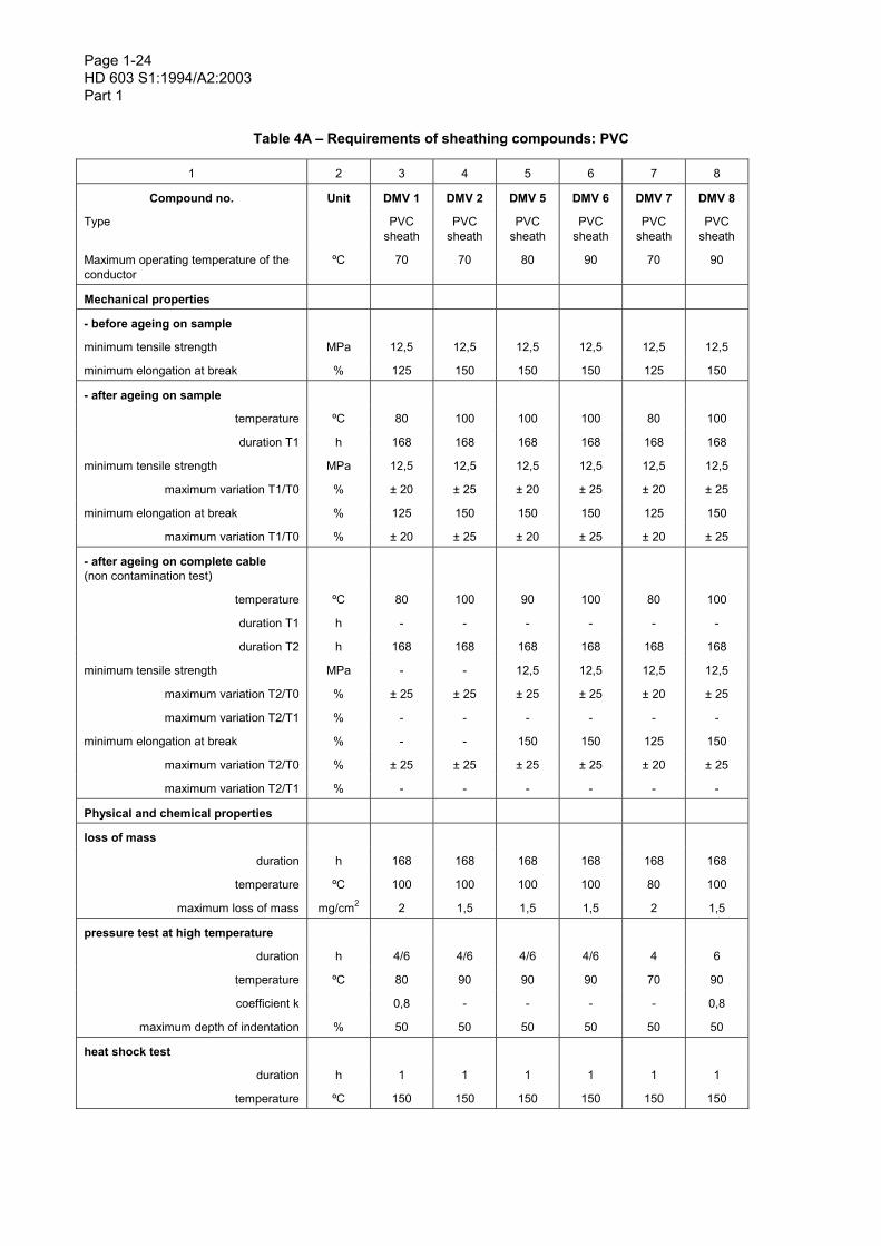
Table 4A Requirements of sheathing compounds: PVC
1 2 3 4 5 6 7 8
Compound no. Unit DMV 1 DMV 2 DMV 5 DMV 6 DMV 7 DMV 8
Type PVC sheath
PVC sheath
PVC sheath
PVC sheath
PVC sheath
PVC sheath
Maximum operating temperature of the conductor
ºC 70 70 80 90 70 90
Mechanical properties
- before ageing on sample
minimum tensile strength MPa 12,5 12,5 12,5 12,5 12,5 12,5
minimum elongation at break % 125 150 150 150 125 150
- after ageing on sample
temperature ºC 80 100 100 100 80 100
duration T1 h 168 168 168 168 168 168
minimum tensile strength MPa 12,5 12,5 12,5 12,5 12,5 12,5
maximum variation T1/T0 % ± 20 ± 25 ± 20 ± 25 ± 20 ± 25
minimum elongation at break % 125 150 150 150 125 150
maximum variation T1/T0 % ± 20 ± 25 ± 20 ± 25 ± 20 ± 25
- after ageing on complete cable (non contamination test)
temperature ºC 80 100 90 100 80 100
duration T1 h - - - - - -
duration T2 h 168 168 168 168 168 168
minimum tensile strength MPa - - 12,5 12,5 12,5 12,5
maximum variation T2/T0 % ± 25 ± 25 ± 25 ± 25 ± 20 ± 25
maximum variation T2/T1 % - - - - - -
minimum elongation at break % - - 150 150 125 150
maximum variation T2/T0 % ± 25 ± 25 ± 25 ± 25 ± 20 ± 25
maximum variation T2/T1 % - - - - - -
Physical and chemical properties
loss of mass
duration h 168 168 168 168 168 168
temperature ºC 100 100 100 100 80 100
maximum loss of mass mg/cm2 2 1,5 1,5 1,5 2 1,5
pressure test at high temperature
duration h 4/6 4/6 4/6 4/6 4 6
temperature ºC 80 90 90 90 70 90
coefficient k 0,8 - - - - 0,8
maximum depth of indentation % 50 50 50 50 50 50
heat shock test
duration h 1 1 1 1 1 1
temperature ºC 150 150 150 150 150 150
Page 1-25 HD 603 S1:1994/A2:2003
Part 1
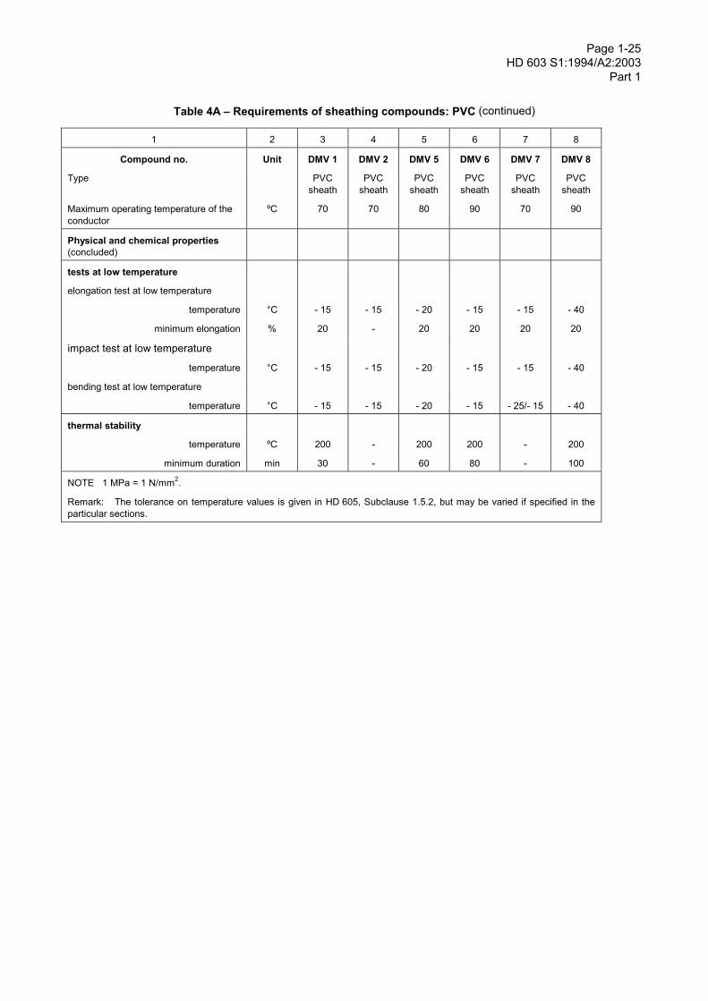
Table 4A Requirements of sheathing compounds: PVC (continued)
1 2 3 4 5 6 7 8
Compound no. Unit DMV 1 DMV 2 DMV 5 DMV 6 DMV 7 DMV 8
Type PVC sheath
PVC sheath
PVC sheath
PVC sheath
PVC sheath
PVC sheath
Maximum operating temperature of the conductor
ºC 70 70 80 90 70 90
Physical and chemical properties (concluded)
tests at low temperature
elongation test at low temperature
temperature °C - 15 - 15 - 20 - 15 - 15 - 40
minimum elongation % 20 - 20 20 20 20
impact test at low temperature
temperature °C - 15 - 15 - 20 - 15 - 15 - 40
bending test at low temperature
temperature °C - 15 - 15 - 20 - 15 - 25/- 15 - 40
thermal stability
temperature ºC 200 - 200 200 - 200
minimum duration min 30 - 60 80 - 100
NOTE 1 MPa = 1 N/mm2.
Remark: The tolerance on temperature values is given in HD 605, Subclause 1.5.2, but may be varied if specified in the particular sections.

Page 1-26 HD 603 S1:1994/A2:2003 Part 1
Table 4A Requirements of sheathing compounds: PVC (continued)
1 2 10 11 12 13 14 15
Compound no. Unit DMV 9 DMV 10 DMV 11 DMV 12 DMV 13 DMV 14
Type PVC sheath
PVC sheath
PVC sheath
PVC sheath
PVC sheath
PVC sheath
Maximum operating temperature of the conductor
ºC 70 90 90 80 90 70
Mechanical properties
- before ageing on sample
minimum tensile strength MPa 12,5 12,5 12,5 12,5 12,5 12,5
minimum elongation at break % 150 150 200 150 125 125
- after ageing on sample
temperature ºC 100 100 100 100 100 80
duration T1 h 168 168 168 168 168 168
minimum tensile strength MPa 12,5 12,5 17,5 12,5 12,5 12,5
maximum variation T1/T0 % ± 25 ± 25 ± 25 ± 25 ± 20 ± 25
minimum elongation at break % 150 150 200 150 125 125
maximum variation T1/T0 % ± 25 ± 25 ± 25 ± 25 ± 20 ± 25
- after ageing on complete cable (non contamination test)
temperature ºC 80 100 100 90 100 80
duration T1 h - - 336 - - -
duration T2 h 168 168 1008 168 168 168
minimum tensile strength MPa 12,5 12,5 - 12,5 - -
maximum variation T2/T0 % ± 25 ± 25 ± 40 ± 25 ± 20 ± 25
maximum variation T2/T1 % - - ± 25 - - -
minimum elongation at break % 150 150 - 150 - -
maximum variation T2/T0 % ± 25 ± 25 ± 40 ± 25 ± 20 ± 25
maximum variation T2/T1 % - - ± 25 - - -
Physical and chemical properties
loss of mass
duration h 168 168 168 168 - 168
temperature ºC 80 100 100 80 - 80
maximum loss of mass mg/cm2 2 1,5 2 2 - 2
pressure test at high temperature
duration h 6 6 4/6 4/6 4/6 4
temperature ºC 80 90 80 80 90 80
coefficient k 0,8 0,8 0,8 0,8 0,6/0,7 0,6 or 0,7
maximum depth of indentation % 50 50 50 50 50 50
heat shock test
duration h 1 1 1 1 1 1
temperature ºC 150 150 150 150 150 150
Page 1-27 HD 603 S1:1994/A2:2003
Part 1
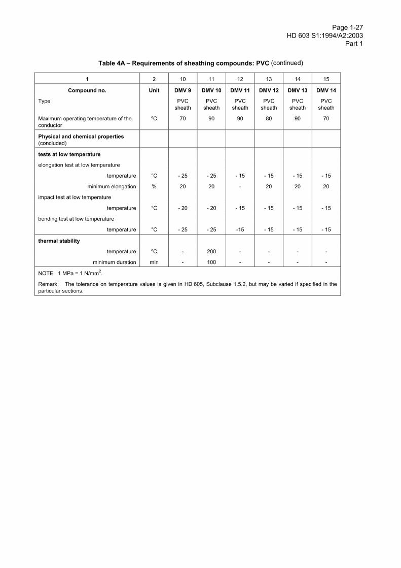
Table 4A Requirements of sheathing compounds: PVC (continued)
1 2 10 11 12 13 14 15
Compound no. Unit DMV 9 DMV 10 DMV 11 DMV 12 DMV 13 DMV 14
Type PVC sheath
PVC sheath
PVC sheath
PVC sheath
PVC sheath
PVC sheath
Maximum operating temperature of the conductor
ºC 70 90 90 80 90 70
Physical and chemical properties (concluded)
tests at low temperature
elongation test at low temperature
temperature °C - 25 - 25 - 15 - 15 - 15 - 15
minimum elongation % 20 20 - 20 20 20
impact test at low temperature
temperature °C - 20 - 20 - 15 - 15 - 15 - 15
bending test at low temperature
temperature °C - 25 - 25 -15 - 15 - 15 - 15
thermal stability
temperature ºC - 200 - - - -
minimum duration min - 100 - - - -
NOTE 1 MPa = 1 N/mm2.
Remark: The tolerance on temperature values is given in HD 605, Subclause 1.5.2, but may be varied if specified in the particular sections.

Page 1-28 HD 603 S1:1994/A2:2003 Part 1
Table 4A Requirements of sheathing compounds: PVC (continued)
1 2 16 17 18 19 20
Compound no. Unit DMV 15 DMV 16 DMV 17 DMV 18 DMV 19
Type PVC sheath
PVC sheath
PVC sheath
PVC sheath
lead free
PVC sheath
Maximum operating temperature of the conductor
ºC 90 90 80 90 80
Mechanical properties
- before ageing on sample
minimum tensile strength MPa 12,5 15 12,5 12,5 12,5
minimum elongation at break % 150 150 150 150 150
- after ageing on sample
temperature ºC 100 90 100 100 100
duration T1 h 168 168 168 168 168
minimum tensile strength MPa 12,5 15 12,5 12,5 12,5
maximum variation T1/T0 % ± 25 ± 25 ± 25 ± 25 ± 25
minimum elongation at break % 150 150 150 150 150
maximum variation T1/T0 % ± 25 ± 25 ± 25 ± 25 ± 25
- after ageing on complete cable (non contamination test)
temperature ºC 100 90 80 100 80
duration T1 h - - - - -
duration T2 h 168 168 168 168 168
minimum tensile strength MPa - -15 - - -
maximum variation T2/T0 % ± 25 ± 25 ± 25 ± 25 ± 25
maximum variation T2/T1 % - - - - -
minimum elongation at break % - 150 - - -
maximum variation T2/T0 % ± 25 ± 25 ± 25 ± 25 ± 25
maximum variation T2/T1 % - - - - -
Physical and chemical properties
loss of mass
duration h 168 168 - 168 168
temperature ºC 100 100 - 100 80
maximum loss of mass mg/cm2 1,5 1,5 - 1,5 2
pressure test at high temperature
duration h 6 4 4/6 4/6 4/6
temperature ºC 90 80 80 80 80
coefficient k 0,6 or 0,7 0,8 0,6 or 0,7 0,8 0,8
maximum depth of indentation % 50 50 50 50 50
heat shock test
duration h 1 1 1 1 1
temperature ºC 150 150 150 150 150
Page 1-29 HD 603 S1:1994/A2:2003
Part 1
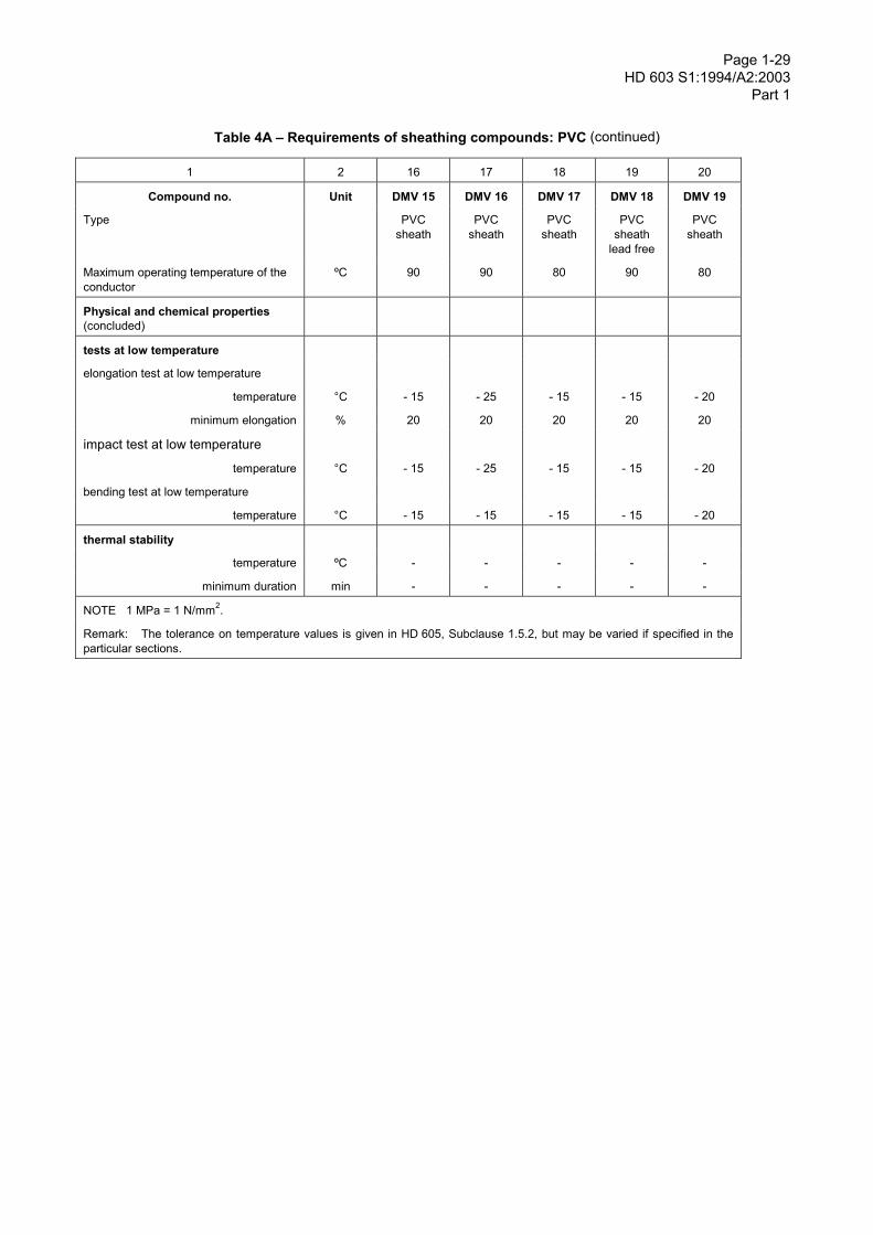
Table 4A Requirements of sheathing compounds: PVC (continued)
1 2 16 17 18 19 20
Compound no. Unit DMV 15 DMV 16 DMV 17 DMV 18 DMV 19
Type PVC sheath
PVC sheath
PVC sheath
PVC sheath
lead free
PVC sheath
Maximum operating temperature of the conductor
ºC 90 90 80 90 80
Physical and chemical properties (concluded)
tests at low temperature
elongation test at low temperature
temperature °C - 15 - 25 - 15 - 15 - 20
minimum elongation % 20 20 20 20 20
impact test at low temperature
temperature °C - 15 - 25 - 15 - 15 - 20
bending test at low temperature
temperature °C - 15 - 15 - 15 - 15 - 20
thermal stability
temperature ºC - - - - -
minimum duration min - - - - -
NOTE 1 MPa = 1 N/mm2.
Remark: The tolerance on temperature values is given in HD 605, Subclause 1.5.2, but may be varied if specified in the particular sections.

Page 1-30 HD 603 S1:1994/A2:2003 Part 1
Table 4A Requirements of sheathing compounds: PVC (continued)
1 2 21 22 23 24 25
Compound no. Unit DMV 20 DMV 21 DMV 22 DMV 23 DMV 24
Type PVC sheath
PVC sheath
PVC sheath
PVC sheath
PVC sheath
Maximum operating temperature of the conductor
ºC 90 90 90 90 70
Mechanical properties
- before ageing on sample
minimum tensile strength MPa 12,5 12,5 12,5 12,5 15
minimum elongation at break % 150 150 125 150 150
- after ageing on sample
temperature ºC 100 100 80 100 90
duration T1 h 168 168 168 168 240
minimum tensile strength MPa 12,5 12,5 12,5 12,5 15
maximum variation T1/T0 % ± 25 ± 25 ± 20 ± 25 ± 25
minimum elongation at break % 150 150 125 150 150
maximum variation T1/T0 % ± 25 ± 25 ± 20 ± 25 ± 25
- after ageing on complete cable (non contamination test)
temperature ºC 100 100 80 100 80
duration T1 h - - - - -
duration T2 h 168 168 168 168 168
minimum tensile strength MPa - - 12,5 - -
maximum variation T2/T0 % ± 25 ± 25 ± 20 ± 25 ± 25
maximum variation T2/T1 % - - - - -
minimum elongation at break % - - 125 - -
maximum variation T2/T0 % ± 25 ± 25 ± 20 ± 25 ± 25
maximum variation T2/T1 % - - - - -
Physical and chemical properties
loss of mass
duration h 168 168 168 168 168
temperature ºC 100 100 80 100 100
maximum loss of mass mg/cm2 1,5 1,5 2 1,5 2
pressure test at high temperature
duration h 4/6 4/6 4/6 4/6 4
temperature ºC 90 90 80 90 80
coefficient k 0,8 0,8 0,6/0,8 - 0,8
maximum depth of indentation % 50 50 50 50 50
heat shock test
duration h 1 1 1 1 1
temperature ºC 150 150 150 150 150
Page 1-31 HD 603 S1:1994/A2:2003
Part 1
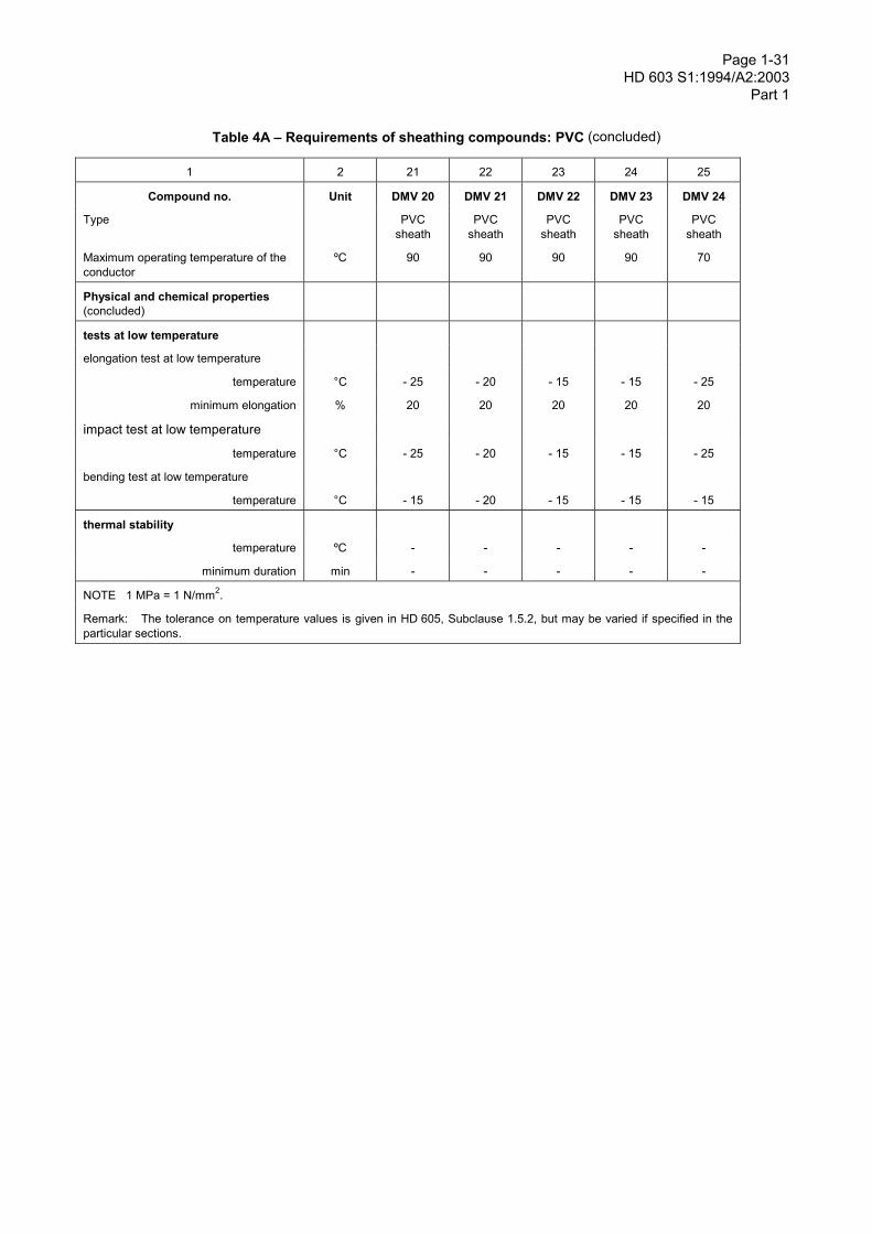
Table 4A Requirements of sheathing compounds: PVC (concluded)
1 2 21 22 23 24 25
Compound no. Unit DMV 20 DMV 21 DMV 22 DMV 23 DMV 24
Type PVC sheath
PVC sheath
PVC sheath
PVC sheath
PVC sheath
Maximum operating temperature of the conductor
ºC 90 90 90 90 70
Physical and chemical properties (concluded)
tests at low temperature
elongation test at low temperature
temperature °C - 25 - 20 - 15 - 15 - 25
minimum elongation % 20 20 20 20 20
impact test at low temperature
temperature °C - 25 - 20 - 15 - 15 - 25
bending test at low temperature
temperature °C - 15 - 20 - 15 - 15 - 15
thermal stability
temperature ºC - - - - -
minimum duration min - - - - -
NOTE 1 MPa = 1 N/mm2.
Remark: The tolerance on temperature values is given in HD 605, Subclause 1.5.2, but may be varied if specified in the particular sections.

Page 1-32 HD 603 S1:1994/A2:2003 Part 1
Table 4B Requirements of sheathing compounds: PE
1 2 3 4 5 6 7 8 9 10
Compound no. Unit DMP 1 DMP 2 DMP 3 DMP 4 DMP 5 DMP 6 DMP 7 DMP 8
Type PE sheath PE sheath PE sheath PE sheath PE sheath PE sheath PE sheath PE sheath
Maximum operating temperature of the conductor
ºC 70 90 80 80 90 90 90 90
Mechanical properties
- before ageing on sample
minimum tensile strength MPa 18 18 10 10 12,5 10 10 10
minimum elongation at break % 300 300 300 300 300 300 300 300
- after ageing on sample
temperature ºC 110 110 100 1O0 110 100 100 100
duration T1 h 336 336 240 240 336 240 240 240
minimum tensile strength MPa - - 10 10 - - - 10
maximum variation T1/T0 % - - - - - - - -
minimum elongation at break % 300 300 300 300 300 300 300 300
maximum variation T1/T0 % - - - - - - - -
- after ageing on complete cable (non contamination test)
temperature ºC 80 100 - - 100 90 100 100
duration T1 h - - - - - - - -
duration T2 h 168 168 - - 168 168 168 168
minimum tensile strength MPa - - - - - - - -
maximum variation T2/T0 % ± 25 - - - - - - -
maximum variation T2/T1 % - - - - - - - -
minimum elongation at break % - 300 - - 300 300 300 300
maximum variation T2/T0 % ± 25 - - - - - - -
maximum variation T2/T1 % - - - - - - - -
Page 1-32 H
D 603 S1:1994/A2:2003
Part 1
Page 1-33 HD 603 S1:1994/A2:2003
Part 1
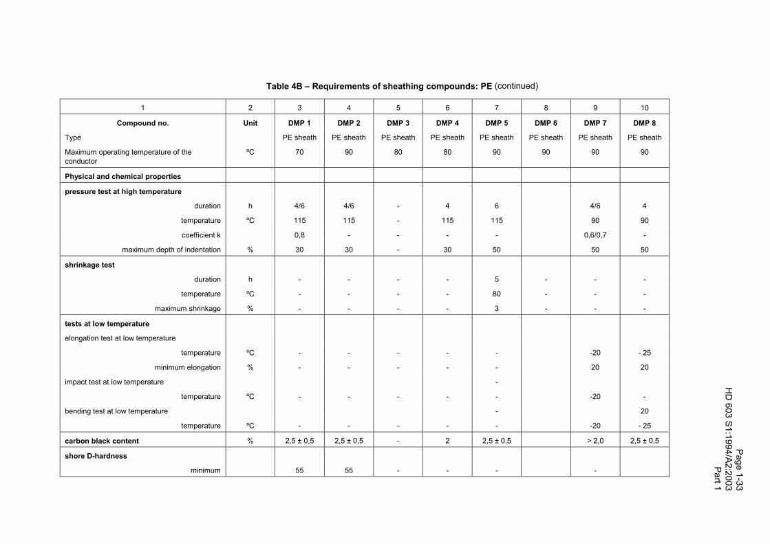
Table 4B Requirements of sheathing compounds: PE (continued)
1 2 3 4 5 6 7 8 9 10
Compound no. Unit DMP 1 DMP 2 DMP 3 DMP 4 DMP 5 DMP 6 DMP 7 DMP 8
Type PE sheath PE sheath PE sheath PE sheath PE sheath PE sheath PE sheath PE sheath
Maximum operating temperature of the conductor
ºC 70 90 80 80 90 90 90 90
Physical and chemical properties
pressure test at high temperature
duration h 4/6 4/6 - 4 6 4/6 4
temperature ºC 115 115 - 115 115 90 90
coefficient k 0,8 - - - - 0,6/0,7 -
maximum depth of indentation % 30 30 - 30 50 50 50
shrinkage test
duration h - - - - 5 - - -
temperature ºC - - - - 80 - - -
maximum shrinkage % - - - - 3 - - -
tests at low temperature
elongation test at low temperature
temperature ºC - - - - - -20 - 25
minimum elongation % - - - - - 20 20
impact test at low temperature -
temperature ºC - - - - - -20 -
bending test at low temperature - 20
temperature ºC - - - - - -20 - 25
carbon black content % 2,5 ± 0,5 2,5 ± 0,5 - 2 2,5 ± 0,5 > 2,0 2,5 ± 0,5
shore D-hardness
minimum 55 55 - - - -
Page 1-33H
D 603 S1:1994/A2:2003
Part 1

Page 1-34 HD 603 S1:1994/A2:2003 Part 1
Table 4B Requirements of sheathing compounds: PE (concluded)
1 2 3 4 5 6 7 8 9 10
Compound no. Unit DMP 1 DMP 2 DMP 3 DMP 4 DMP 5 DMP 6 DMP 7 DMP 8
Type PE sheath PE sheath PE sheath PE sheath PE sheath PE sheath PE sheath PE sheath
Maximum operating temperature of the conductor
ºC 70 90 80 80 90 90 90 90
Physical and chemical properties (concluded)
melt index - - - - - - - -
maximum - - 0,4 0,4 - - -
stress cracking resistance
requirement no cracks no cracks - - - - - -
duration h 48 1 000 - - - - - -
NOTE 1 MPa = 1 N/mm2.
Remark: The tolerance on temperature values is given in HD 605, Subclause 1.5.2, but may be varied if specified in the particular sections.
Page 1-34 H
D 603 S1:1994/A2:2003
Part 1

Page 1-35 HD 603 S1:1994/A2:2003
Part 1
Table 4C Requirements of sheathing compound: PO
1 2 3
Compound no. Unit DMO 1
Type PO sheath
Maximum operating temperature of the conductor ºC 90
Mechanical properties
- before ageing on sample
minimum tensile strength MPa 15
minimum elongation at break % 500
- after ageing on sample
temperature ºC 110 ± 2
duration T1 h 168
minimum tensile strength MPa -
maximum variation T1/T0 % -
minimum elongation at break % 300
maximum variation T1/T0 % -
- after ageing on complete cable (non contamination test)
temperature ºC 110 ± 2
duration T1 h -
duration T2 h 336
minimum tensile strength MPa -
maximum variation T2/T1 % -
minimum elongation at break % 300
maximum variation T2/T1 % -
Physical and chemical properties
loss of mass
duration h 168
temperature ºC 100 ± 2
maximum loss of mass mg/cm2 0,5
pressure test at high temperature
duration h 6
temperature ºC 115 ± 2
coefficient k - 0,7
maximum depth of identation % 50
tear resistance test
temperature ºC 20 ± 5
minimum resistance % 24
shrinkage test
duration h 5 x 5
temperature ºC 80 ± 2
0maximum shrinkage % 7
NOTE 1 MPa = 1 N/mm2.
Remark: The tolerance on temperature values is given in HD 605, Subclause 1.5.2, but may be varied if specified in the particular sections.
Page 1-36 HD 603 S1:1994/A2:2003 Part 1
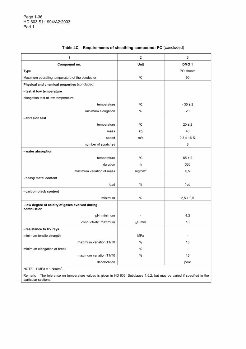
Table 4C Requirements of sheathing compound: PO (concluded)
1 2 3
Compound no. Unit DMO 1
Type PO sheath
Maximum operating temperature of the conductor ºC 90
Physical and chemical properties (concluded)
- test at low temperature
elongation test at low temperature
temperature ºC - 30 ± 2
minimum elongation % 20
- abrasion test
temperature ºC 20 ± 2
mass kg 48
speed m/s 0,3 ± 15 %
number of scratches 8
- water absorption
temperature ºC 85 ± 2
duration h 336
maximum variation of mass mg/cm2 0,5
- heavy metal content
lead % free
- carbon black content
minimum % 2,5 ± 0,5
- low degree of acidity of gases evolved during combustion
pH: minimum - 4,3
conductivity: maximum µS/mm 10
- resistance to UV rays
minimum tensile strength MPa -
maximum variation T1/T0 % 15
minimum elongation at break % -
maximum variation T1/T0 % 15
decoloration poor
NOTE 1 MPa = 1 N/mm2.
Remark: The tolerance on temperature values is given in HD 605, Subclause 1.5.2, but may be varied if specified in the particular sections.

Page 1-37 HD 603 S1:1994/A2:2003
Part 1
Table 5 Thickness of insulation
1 2 3 4
Nominal cross-sectional area of conductor
Thickness of insulation mm
mm2 PVC XLPE and HEPR EPR
1,5 and 2,5 0,8 0,7 1,0
4 and 6 1,0 0,7 1,0
10 and 16 1,0 0,7 1,0
25 and 35 1,2 0,9 1,2
50 1,4 1,0 1,4
70 1,4 1,1 1,4
95 1,6 1,1 1,6
120 1,6 1,2 1,6
150 1,8 1,4 1,8
185 2,0 1,6 2,0
240 2,2 1,7 2,2
300 2,4 1,8 2,4
400 2,6 2,0 2,6
500 2,8 2,2 2,8
630 2,8 2,4 2,8
800 2,8 2,6 2,8
1 000 3,0 2,8 3,0

Page 1-38 HD 603 S1:1994/A2:2003 Part 1
BLANK PAGE

Page 3-F-0 HD 603 S1:1994/A2:2003
Part 3 Section F
SECTION 3-F - CABLES WITH AND WITHOUT CONCENTRIC CONDUCTOR (TYPE 3F)
Replace pages
3-F-4; 3-F-8 and 3-F-11
by the following A2 referred new pages
3-F-4; 3-F-8 and 3-F-11:


Page 3-F-4 HD 603 S1:1994/A2:2003 Part 3 Section F
2 Design requirements (continued)
Cable component Requirements
HD Additional
5.1 Design One layer of copper wires with a copper contact tape touching the wires. A separation layer of suitable material may be put on the concentric conductor. The lay length of the wires shall not be more than 50 times the diameter measured under the wires. If the copper wires have been laid in wave form, the angle of lay has to be such that the length of the wire is the same as calculated from the condition above. Contact tape may be solid copper or a flat bundle of copper wires.The lay length contact tape shall not be more than 20 times the diameter under contact tape. Optional: Use of an additional metallic layer, which shall be lapped and in contact with copper wires.
5.2 DC resistance, maximum Appendix, Tables 1 and 2
5.3 Cross section of concentric conductor
Appendix, Tables 1 and 2
5.4 Distance between wires a) measured mean clearance between individual (adjacent) wires b) number of clearances comprised between 4 mm and 8 mm maximum
≤ 4,0 mm less than 5 % of the clearances
5.5 Size of contact tape Thickness: ≥ 0,1 mm Width: ≥ 3 mm
6 Outer sheath HD 603-1 Subclause 5.8
6.1 Material HD 603-1, Table 4A - type DMV 9
Weather resistant PVC
6.2 Colour Black, throughout the entire thickness
6.3 Thickness a) nominal thickness b) minimum thickness c) average thickness
Appendix, Tables 3 and 4 The thickness shall at no point be less than the nominal thickness by more than 0,1 mm + 15 % of the nominal value Not less than the nominal thickness
7 Marking HD 603-1 Subclause 3
All code designation markings have to be embossed, engraved or printed on the outer sheath. Sequential cable length marking in meter on the outersheath is required as mandatory. Additional markings are accepted.
7.1 Indication of origin on the outer sheath
Manufacturers name or trademark which shall be legally protected and from which the manufacturer can be identified

Page 3-F-8 HD 603 S1:1994/A2:2003 Part 3 Section F
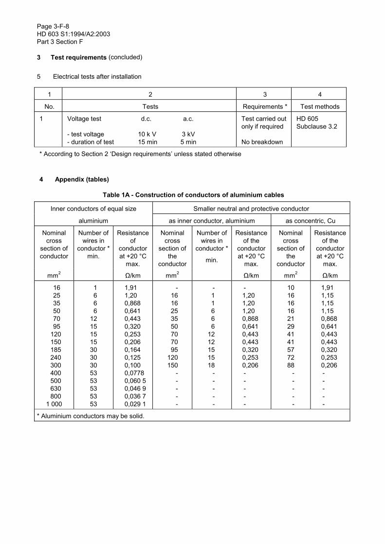
3 Test requirements (concluded) 5 Electrical tests after installation
1 2 3 4
No. Tests Requirements * Test methods
1
Voltage test d.c. a.c. - test voltage 10 k V 3 kV - duration of test 15 min 5 min
Test carried out only if required No breakdown
HD 605 Subclause 3.2
* According to Section 2 Design requirements unless stated otherwise
4 Appendix (tables)
Table 1A - Construction of conductors of aluminium cables
Inner conductors of equal size Smaller neutral and protective conductor
aluminium as inner conductor, aluminium as concentric, Cu
Nominal cross
section of conductor
Number of wires in
conductor * min.
Resistance of
conductor at +20 °C
max.
Nominal cross
section of the
conductor
Number of wires in
conductor *
min.
Resistance of the
conductorat +20 °C
max.
Nominal cross
section of the
conductor
Resistance of the
conductorat +20 °C
max.
mm2 Ω/km mm2 Ω/km mm2 Ω/km
16 25 35 50 70 95 120 150 185 240 300 400 500 630 800 1 000
1 6 6 6
12 15 15 15 30 30 30 53 53 53 53 53
1,91 1,20 0,868 0,641 0,443 0,320 0,253 0,206 0,164 0,125 0,100 0,0778 0,060 5 0,046 9 0,036 7 0,029 1
- 16 16 25 35 50 70 70 95
120 150
- - - - -
- 1 1 6 6 6
12 12 15 15 18
- - - - -
- 1,20 1,20 1,20 0,868 0,641 0,443 0,443 0,320 0,253 0,206 - - - - -
10 16 16 16 21 29 41 41 57 72 88
- - - - -
1,91 1,15 1,15 1,15 0,868 0,641 0,443 0,443 0,320 0,253 0,206 - - - - -
* Aluminium conductors may be solid.

Page 3-F-11 HD 603 S1:1994/A2:2003
Part 3 Section F
4 Appendix (continued)
Table 3 - Thickness of inner covering and outer sheath of aluminium cables
Cable type Number and cross section
of the conductors
Approximate value of the thickness
of the inner covering
Nominal thickness of the outer sheath
mm2 lapped, mm extruded, mm mm
AMMK AMMK AMMK AMCMK AMCMK
1 x 35 1 x 50 1 x 70 1 x 95 1 x 120 1 x 150 1 x 185 1 x 240 1 x 300 1 x 400 1 x 500 1 x 630 1 x 800 1 x 1 000 3 x 50 + 25 3 x 70 + 35 3 x 95 + 50 3 x 120 + 70 3 x 150 + 70 3 x 185 + 95 3 x 240 + 120 3 x 300 + 150 4 x 16 4 x 35 4 x 70 4 x 120 4 x 185 4 x 300 3 x 16 Al + 10 Cu 3 x 25 Al + 16 Cu 3 x 35 Al + 16 Cu 3 x 50 Al + 16 Cu 3 x 70 Al + 21 Cu 3 x 95 Al + 29 Cu 3 x 120 Al + 41 Cu 3 x 150 Al + 41 Cu 3 x 185 Al + 57 Cu 3 x 240 Al + 72 Cu 3 x 300 Al + 88 Cu 3 x 50 Al + 25 Al + 16 Cu 3 x 70 Al + 35 Al + 21 Cu 3 x 95 Al + 50 Al + 29 Cu 3 x 120 Al + 70 Al + 41 Cu 3 x 150 Al + 70 Al + 41 Cu 3 x 185 Al + 95 Al + 57 Cu 3 x 240 Al + 120 Al + 72 Cu 3 x 300 Al + 150 Al + 88 Cu
- - - - - - - - - - - - - -
0,4 0,4 0,4 0,4 0,4 0,6 0,6 0,6
0,4 0,4 0,4 0,4 0,6 0,6
0,4 0,4 0,4 0,4 0,4 0,4 0,4 0,4 0,6 0,6 0,6
0,4 0,4 0,4 0,4 0,4 0,6 0,6 0,6
- - - - - - - - - - - - -
1,0 1,2 1,2 1,4 1,4 1,4 1,6 1,6
1,0 1,0 1,2 1,4 1,6 1,6
1,0 1,0 1,0 1,0 1,2 1,2 1,2 1,4 1,4 1,6 1,6
1,0 1,2 1,2 1,2 1,4 1,4 1,6 1,6
1,4 1,4 1,4 1,5 1,5 1,6 1,7 1,8 1,9 2,0 2,1 2,2 2,3 2,5
1,9 2,0 2,2 2,3 2,4 2,6 2,8 2,9
1,8 1,8 2,1 2,3 2,7 3,1
1,8 1,8 1,8 1,9 2,0 2,2 2,3 2,4 2,6 2,8 3,0
1,9 2,0 2,2 2,3 2,4 2,6 2,8 3,0


Page 3-G-0 HD 603 S1:1994/A2:2003
Part 3 Section G
SECTION 3-G - CABLES WITH (TYPE 3G-1) OR WITHOUT (TYPE 3G-2) CONCENTRIC CONDUCTOR
Replace Section 3-G
by the following A2 referred new Section 3-G:


Page 3-G-1 HD 603 S1:1994/A2:2003
Part 3 Section G
SECTION 3-G - CABLES WITH (TYPE 3G-1) OR WITHOUT (TYPE 3G-2) CONCENTRIC CONDUCTOR

Page 3-G-2 HD 603 S1:1994/A2:2003 Part 3 Section G
CONTENTS
1 General--------------------------------------------------------------------------------------------------------------------------- 4
2 Design requirements---------------------------------------------------------------------------------------------------------- 5
1 Conductor ------------------------------------------------------------------------------------------------------------- 5 1.1 Material 1.2 Dimensions of stranded circular conductors 1.3 Dimensions of sector-shaped conductors 1.4 Tensile strength for aluminium conductors 1.5 Crossing points for stranded conductors 1.6 Conductor resistance 1.7 Permissible conductor types 1.8 Conductors with reduced cross-sectional area 1.9 Additional core with 1,5 mm2 conductor
2 Insulation -------------------------------------------------------------------------------------------------------------- 6 2.1 Material 2.2 Insulation thickness 2.3 Core identification
3 Assembly of cores--------------------------------------------------------------------------------------------------- 6 3.1 Assembly 3.2 Interstice fillers
4 Inner covering -------------------------------------------------------------------------------------------------------- 7 4.1 Design 4.2 Thickness
5 Concentric conductor----------------------------------------------------------------------------------------------- 7 5.1 Design 5.2 DC resistance 5.3 Copper binder tapes 5.4 Distance between wires
6 Outer sheath---------------------------------------------------------------------------------------------------------- 8 6.1 Material 6.2 Colour 6.3 Thickness
7 Outer diameter ------------------------------------------------------------------------------------------------------- 8
8 Marking on outer sheath------------------------------------------------------------------------------------------- 8 8.1 Indication of origin and year of manufacturing 8.2 Code designation of design and rated voltage U (kV) 8.3 Continuity of marks 8.4 Durability 8.5 Legibility 8.6 Compliance with HD 603-3G 8.7 Meter marking
9 Type designation ---------------------------------------------------------------------------------------------------- 9
3 Test requirements ------------------------------------------------------------------------------------------------------------- 9
1 Routine tests --------------------------------------------------------------------------------------------------------- 9
2 Sample tests---------------------------------------------------------------------------------------------------------10
3 Type tests, electrical-----------------------------------------------------------------------------------------------11
4 Type tests, non-electrical -----------------------------------------------------------------------------------------11
5 Electrical tests after installation ---------------------------------------------------------------------------------13

Page 3-G-3 HD 603 S1:1994/A2:2003
Part 3 Section G
4 Guide to use -------------------------------------------------------------------------------------------------------------------14
1 Recommendations for use --------------------------------------------------------------------------------------14
2 Recommendations for storage and transport ---------------------------------------------------------------14
3 Recommendations for cable laying----------------------------------------------------------------------------15
4 Recommendations for fault detection-------------------------------------------------------------------------17
5 Current-carrying capacity (recommended values) --------------------------------------------------------------------18
6 Appendix (tables) -------------------------------------------------------------------------------------------------------------20 REFERENCES References are made in Section 3-G of HD 603, to other parts of this HD and to other Harmonization Documents and International Standards as follows:
HD 383 Conductors of insulated cables First supplement: Guide to the dimensional limits of circular conductors (endorsing IEC 60228 and 60228A)
HD 402 Standard colours for insulation for low-frequency cables and wires
HD 605 Electric cables Additional test methods
EN 50265 (series) Common test methods for cables under fire conditions Test for resistance to vertical flame propagation for a single insulated conductor or cable
EN 60811 (series) Insulating and sheathing materials of electric cables Common test methods
IEC 60183 Guide to the selection of high-voltage cables
IEC 60502-1 Power cables with extruded insulation and their accessories for rated voltages from 1 kV (Um = 1,2 kV) up to 30 kV (Um = 36 kV) Part 1: Cables for rated voltages from 1 kV (Um = 1,2 kV) and 3 kV (Um = 3,6 kV)
In all cases reference to another HD or International Standard implies the latest edition of that document.

Page 3-G-4 HD 603 S1:1994/A2:2003 Part 3 Section G
1 General
This standard specifies the construction, dimensions and test requirements of power cables with PVC insulation and with (type 3G-1)or without (3G-2) concentric conductor for rated voltage U0/U of 0,6/1 kV.
(a) Insulating materials
The insulation covered by this standard shall consist of polyvinyl chloride and correspond to HD 603-1, Table 1, DIV 4.
(b) Rated voltage
0,6/1 kV
(i) Definitions: see HD 603-1, Subclause 2.3 and HD 603-3G, Section 4, Subclause 1.2.
(ii) Cables covered by this standard are suitable to Category B according to IEC 60183. The duration of an earth fault may not exceed 8 h. The total duration of earth faults in any year should not exceed 125 h.
(c) Highest rated temperatures for the insulating compound
(i) Normal operation 70 °C
(ii) Short-circuit for cross sections area ≤ 300 mm2 160 °C (5 sec. maximum duration) for cross sections area > 300 mm2 140 °C
(d) Sheathing material
The sheathing materials shall be suitable for the maximum rated conductor temperature. It shall consist of PVC and correspond to HD 603-1, Table 4A, DMV 5.
(e) Test conditions
See HD 605

Page 3-G-5 HD 603 S1:1994/A2:2003
Part 3 Section G
2 Design requirements
No. Cable component Requirements
HD Additional
1 Conductor HD 603-1 Subclause 5.1
1.1 Material
a) General b) Purity of Aluminium
HD 603-1 Subclause 5.1.1
≥ 99,5 %
1.2 Dimensions of circular conductors (diameter) a) solid - copper conductor - aluminium conductor b) stranded, compacted c) stranded, non compacted copper conductor
HD 383 Table 1, column 2 Table 2, columns 2, 3 Table 2, columns 4, 5 Table 1, column 3
All cross sections ≥ 50 mm2 shall be compacted
1.3 Dimensions of sector-shaped conductors a) solid aluminium 90/120° b) stranded 90/120° 60/100°
Appendix, Table 1 Appendix, Table 2 Appendix, Table 3
1.4 Tensile strength for aluminium conductors a) wires for stranded conductors before stranding b) solid conductors after cabling up to 25 mm2 35 and 50 mm2 70 mm2 and above
between 130 and 200 N/mm2 100 to 130 N/mm2 80 to 110 N/mm2 60 to 90 N/mm2
1.5 Crossing points for stranded conductors Length of area of contact of two crossing wires of the two outer layers (only for layers laid-up in the same direction)
≤ 12 times wire diameter
NOTE The area of contact is the projection of one wire onto the underneath (theoretical value).
1.6 Conductor Resistance HD 383
1.7 Permissible conductor types Appendix, Table 4

Page 3-G-6 HD 603 S1:1994/A2:2003 Part 3 Section G
2 Design requirements (continued)
No. Cable component Requirements
HD Additional
1.8 Conductor with reduced cross-sectional area a) number b) cross-sectional area c) arrangement
1 Appendix, Table 5 Insulated, laid-up or concentric without insulation applied over inner covering
1.9 Additional core of 1,5 mm2 with solid conductor a) allowed number b) arrangement
1 In an outer interstice within projection from the diameter of the laid-up cores and no distortion of the core-insulation
2 Insulation HD 603-1 Subclause 5.2
2.1 Material HD 603-1, Table 1 compound DIV 4
2.2 Insulation thickness a) nominal value b) mean, minimum value
HD 603-1 Table 5 HD 603-1 Subclause 5.2.3
NOTE The thickness of any separating tape over the insulation shall not be included in the thickness of the insulation.
2.3 Core identification a) colour of cores of multi- core cables without concentric conductor b) colour of cores of multi- core cables with concentric conductor (only cores) c) colour of add. core with 1,5 mm2 conductor d) colour of cores of single- core cables
HD 603-1 Subclause 4
Appendix, Table 6 columns 2 and 3 Appendix, Table 6 column 4 black black or green/yellow
3 Assembly of cores
3.1 Assembly HD 603-1 Subclause 5.3
Cores of multi-core cables shall be laid-up; binder tapes are permitted
3.2 Interstice fillers a) inner interstices three-core cables with concentric conductor and four-core cables both with cross sections ≥ 35 mm2
and extruded inner covering b) outer interstices
HD 603-1 Subclause 5.4
Non-hygroscopic filler to be applied in the inner interstice The central filler shall well fill the inner interstice Fillers are permitted

Page 3-G-7 HD 603 S1:1994/A2:2003
Part 3 Section G
2 Design requirements (continued)
No. Cable component Requirements
HD Additional
4 Inner covering HD 603-1 Subclause 5.5
4.1 Design for cables with a) copper conductor b) aluminium conductor
Taped paper or synthetic or extruded bedding Extruded bedding
4.2 Thickness a) for cables with extruded inner covering - without concentric conductor - with concentric conductor
Appendix, Table 7 column 2 (minimum value according to column 3) Strong penetration of wires into the extruded inner covering is not considered as faulty but the inner covering shall cover the laid-up cores without gaps
b) cables with lapped inner covering for fictitious diameters 1)
over laid-up cores - up to and including 40 mm - above 40 mm
0,4 mm (approx. value) 0,6 mm (approx. value) The thickness shall at no point fall be-low this value by more than 50 %.
5 Concentric conductor (if required)
HD 603-1 Subclause 5.7
5.1 Design Copper wires with one or two copper binder tapes over the inner covering
5.2 DC resistance HD 383 For cables with aluminium conductor (phase) the d.c. resistance of the concentric copper conductor shall not exceed that of an Al-conductor of the nominal cross-sectional area given.
5.3 Copper binder tapes, a) number, minimum cross- sectional area and maximum clearance between two adjacent copper binder tapes b) thickness
Appendix, Table 8 0,1 mm to 0,3 mm
5.4 Clearance between adjacent wires a) mean clearance between individual (adjacent) wires b) maximum clearance between two adjacent wires
4 mm (calculated value) 8 mm
1) According to IEC 60502-1, Annex A.

Page 3-G-8 HD 603 S1:1994/A2:2003 Part 3 Section G
2 Design requirements (continued)
No. Cable component Requirements
HD Additional
6 Outer sheath HD 603-1 Subclause 5.8
6.1 Material HD 603-1 Table 4A compound DMV 5
6.2 Colour Black, throughout the entire thickness
6.3 Thickness a) nominal thickness b) minimum thickness
ts = 0,035 DA + 1,0 mm DA = fictitious diameter 1) under the sheath The nominal thickness shall not be less than 1,8 mm The thickness shall at no point be less than the nominal thickness
7 Outer diameter (minimum and maximum values)
For preferred cable types Appendix, Tables 9 -11 For cables with additional components, for example to improve short-circuit protection, the indicated values may be exceeded.
8 Marking on the outer sheath HD 603-1 Subclause 3
8.1 Indication of origin and Year of manufacturing
HD 603-1 Subclause 3.1
Manufacturers name or trademark which shall be legally protected and from which the manufacturer can be identified
8.2 Code designation of design and rated voltage U (kV)
Appendix, Table 12
8.3 Continuity of marks HD 603-1 Subclause 3.2
Distance between the beginning of one mark and the beginning of the next ≤ 50 cm
8.4 Durability HD 603-1 Subclause 3.3
8.5 Legibility HD 603-1 Subclause 3.4
8.6 Compliance with HD 603-3G Approval marking according to agreed system
1) According to IEC 60502-1, Annex A.
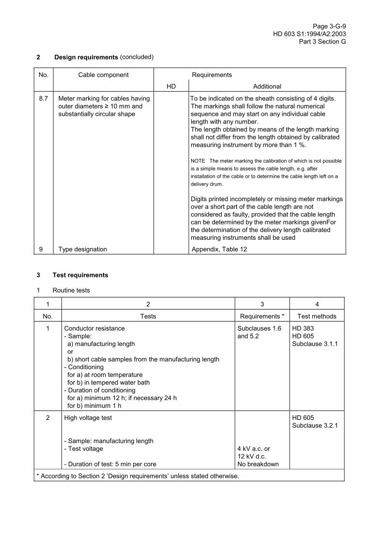
Page 3-G-9 HD 603 S1:1994/A2:2003
Part 3 Section G
2 Design requirements (concluded)
No. Cable component Requirements
HD Additional
8.7 Meter marking for cables having outer diameters ≥ 10 mm and substantially circular shape
To be indicated on the sheath consisting of 4 digits. The markings shall follow the natural numerical sequence and may start on any individual cable length with any number. The length obtained by means of the length marking shall not differ from the length obtained by calibrated measuring instrument by more than 1 %. NOTE The meter marking the calibration of which is not possible is a simple means to assess the cable length, e.g. after installation of the cable or to determine the cable length left on a delivery drum. Digits printed incompletely or missing meter markings over a short part of the cable length are not considered as faulty, provided that the cable length can be determined by the meter markings givenFor the determination of the delivery length calibrated measuring instruments shall be used
9 Type designation Appendix, Table 12
3 Test requirements
1 Routine tests
1 2 3 4
No. Tests Requirements * Test methods
1 Conductor resistance - Sample: a) manufacturing length or b) short cable samples from the manufacturing length - Conditioning for a) at room temperature for b) in tempered water bath - Duration of conditioning for a) minimum 12 h; if necessary 24 h for b) minimum 1 h
Subclauses 1.6 and 5.2
HD 383 HD 605 Subclause 3.1.1
2 High voltage test - Sample: manufacturing length - Test voltage - Duration of test: 5 min per core
4 kV a.c. or 12 kV d.c. No breakdown
HD 605 Subclause 3.2.1
* According to Section 2 Design requirements unless stated otherwise.

Page 3-G-10 HD 603 S1:1994/A2:2003 Part 3 Section G
3 Test requirements (continued) 2 Sample tests 1)
1 2 3 4
No. Tests Requirements * Test methods
1 Construction of conductor Subclauses 1.2 to 1.5
EN 60811-1-1 Subclause 8.3 and by inspection
2 Insulation - Thickness 2) 3)
Subclause 2.2
EN 60811-1-1 Subclause 8.1
3 Inner covering - Thickness
Subclause 4 EN 60811-1-1 Subclause 8.2
4 Concentric conductor - Dimensions of copper binder tapes - Clearance between wires
Subclause 5.3 Subclause 5.4
HD 605 Subclause 2.1.4.2 HD 603-3G, Section 2 (Design), item 5.4
5 Sheath - Thickness 3)
Subclause 6.3 EN 60811-1-1 Subclause 8.2
6 Outer diameter Subclause 7 EN 60811-1-1 Subclause 8.3
7 Marking Subclause 8 Test by inspection 1) Sample tests shall be carried out on 10 % of a manufacturing lot of the same cable type, i.e. at least on one cable length.
If any ample should fail in any of the sample tests requested it is permitted to choose one or two additional sample(s) from the same cable length and to submit the additional sample(s) to the test or tests in which the original sample failed.
The samples shall be taken at least 0,5 m from the cable end(s).
For the resampling procedure, the following rules apply:
- number of samples to be taken as for the first test,
- if for the first test one sample from both cable ends has to be taken, is it deemed sufficient to resample one additional sample from the cable end the first sample of which failed. 2) Measurement at 10 % of the cores, at least at 4 cores. 3) One sample of each end of the cable in a distance of approximate 50 cm from the ends.
* According to Section 2 Design requirements unless stated otherwise.
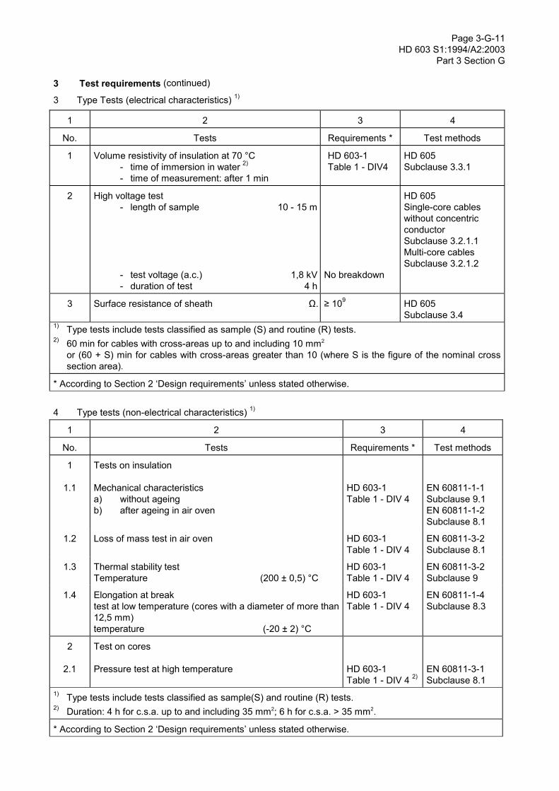
Page 3-G-11 HD 603 S1:1994/A2:2003
Part 3 Section G
3 Test requirements (continued) 3 Type Tests (electrical characteristics) 1)
1 2 3 4
No. Tests Requirements * Test methods
1 Volume resistivity of insulation at 70 °C - time of immersion in water 2) - time of measurement: after 1 min
HD 603-1 Table 1 - DIV4
HD 605 Subclause 3.3.1
2 High voltage test - length of sample 10 - 15 m - test voltage (a.c.) 1,8 kV - duration of test 4 h
No breakdown
HD 605 Single-core cables without concentric conductor Subclause 3.2.1.1 Multi-core cables Subclause 3.2.1.2
3 Surface resistance of sheath Ω. ≥ 109 HD 605 Subclause 3.4
1) Type tests include tests classified as sample (S) and routine (R) tests. 2) 60 min for cables with cross-areas up to and including 10 mm2
or (60 + S) min for cables with cross-areas greater than 10 (where S is the figure of the nominal cross section area).
* According to Section 2 Design requirements unless stated otherwise. 4 Type tests (non-electrical characteristics) 1)
1 2 3 4
No. Tests Requirements * Test methods
1
1.1
Tests on insulation Mechanical characteristics a) without ageing b) after ageing in air oven
HD 603-1 Table 1 - DIV 4
EN 60811-1-1 Subclause 9.1 EN 60811-1-2 Subclause 8.1
1.2 Loss of mass test in air oven HD 603-1 Table 1 - DIV 4
EN 60811-3-2 Subclause 8.1
1.3 Thermal stability test Temperature (200 ± 0,5) °C
HD 603-1 Table 1 - DIV 4
EN 60811-3-2 Subclause 9
1.4 Elongation at break test at low temperature (cores with a diameter of more than12,5 mm) temperature (-20 ± 2) °C
HD 603-1 Table 1 - DIV 4
EN 60811-1-4 Subclause 8.3
2
2.1
Test on cores Pressure test at high temperature
HD 603-1 Table 1 - DIV 4 2)
EN 60811-3-1 Subclause 8.1
1) Type tests include tests classified as sample(S) and routine (R) tests. 2) Duration: 4 h for c.s.a. up to and including 35 mm2; 6 h for c.s.a. > 35 mm2.
* According to Section 2 Design requirements unless stated otherwise.

Page 3-G-12 HD 603 S1:1994/A2:2003 Part 3 Section G
3 Test requirements (continued) 4 Type tests (non-electrical characteristics) (continued)
1 2 3 4
No. Tests Requirements * Test methods
2.2 Heat shock test HD 603-1 Table 1 - DIV 4 No cracks
EN 60811-3-1 Subclause 9.1
2.3 Bending test at low temperature on cores with a diameter up to and including 12,5 mm Temperature (-20 ± 2) °C
HD 603-1 Table 1 - DIV 4 No cracks
EN 60811-1-4 Subclause 8.1
2.4 Water absorption Electrical test procedure Temperature of water bath (70 ± 3) °C a) Pre-test at a.c. voltage Duration of immersion 24 h Duration of test 5 min Test voltage 6 kV b) Main test with d.c. voltage Duration of test 10 x 24 h for insulation thicknesses with a nominal value of 0,8 mm 1 kV 1,0 mm 1,2 kV 1,2 and 1,4 mm 1,5 kV 1,6 and 1,8 mm 2,0 kV 2,0 to 3,0 mm 2,5 kV
HD 603-1 Table 1 -DIV 4 No breakdown no breakdown
EN 60811-1-3 Subclause 9.1 (but test requirements according to column 2)
3
3.1
Tests on sheath Mechanical properties a) without ageing b) after ageing in air oven
HD 603-1 Table 4A - DMV 5
EN 60811-1-1 Subclause 9.2 EN 60811-1-2 Subclause 8.1 (ageing)
3.2 Pressure test at high temperature HD 603-1 Table 4A - DMV 5 1)
EN 60811-3-1 Subclause 8.2
3.3 Thermal stability test Temperature (200 ± 0,5) °C
HD 603-1 Table 4A - DMV 5
EN 60811-3-2 Subclause 9
3.4 Elongation test at low temperature for cables with a diameter over 12,5 mm Temperature: (-20 ± 2) °C
HD 603-1 Table 4A - DMV 5 Elongation at break ≥ 20 %
EN 60811-1-4 Subclause 8.4
3.5 Loss of mass test in air oven HD 603-1 Table 4A - DMV 5
EN 60811-3-2 Subclause 8.2
3.6 Heat shock test HD 603-1 Table 4A - DMV 5
EN 60811-3-1 Subclause 9.2
1) Duration: 4 h for outer diameters of the cable ≤ 12,5 mm, 6 h for outer diameters of the cable > 12,5 mm.
* According to Section 2 Design requirements unless stated otherwise.

Page 3-G-13 HD 603 S1:1994/A2:2003
Part 3 Section G
3 Test requirements (concluded) 4 Type tests (non-electrical characteristics; concluded)
1 2 3 4
No. Tests Requirements * Test methods
4
4.1
Tests on complete cable Bending test at low temperature for cables with diameters up to and including 12,5 mm Temperature: (- 20 ± 2) °C
No cracks
EN 60811-1-4 Subclause 8.2
4.2 Impact test at low temperature Temperature (-20 ± 2) °C
HD 603-1 Table 4A - DMV 5 No cracks
EN 60811-1-4 Subclause 8.5.
4.3 Ageing of complete cable HD 603-1 Table 1 - DIV 4 Table 4A - DMV 5
EN 60811-1-2 Subclause 8.1.4
4.4
Performance at high temperature Duration 7 x 24 h Temperature (120 ± 2) °C
HD 605 Subclause 2.4.13
4.5 Test under fire conditions Flame propagation
EN 50265-1 EN 50265-1
* According to Section 2 Design requirements unless stated otherwise. 5 Electrical tests after installation, if required
1 2 3 4
No. Tests Requirements * Test methods
1
DC voltage test - test voltage 5,6 - 8 kV - duration of test 15 - 30 min
No breakdown
* According to Section 2 Design requirements unless stated otherwise.

Page 3-G-14 HD 603 S1:1994/A2:2003 Part 3 Section G
4 Guide to use 1 Recommendations for use
1 2 3
No. Terms Basic requirements
1 Permissible applications Cables specified according to this HD may be laid: - indoors and outdoors - in soil - in water - in concrete
2 Highest permissible voltage - DC systems 1,8 kV - AC systems - single-phase both conductors insulated 1,4 kV one conductor earthed 0,7 kV - three-phase cables system 1,2 kV however three-phase cables with concentric conductor and cross-sectional area from 240 mm2 upwards 3,6 kV
3 Precautions against electric shock Cables without metallic covering are suitable for Class II equipment.
4 Concentric conductor May be used as PE-conductor, PEN conductor or as a screen.
2 Recommendations for storage and transport
1 2 3
No. Terms Basic requirements
1
1.1
1.2
1.3
Delivery Distance between the outer cable layer and the head of the flange Barrel of delivery drum Cable sealing end
- 2 x cable diameter but at least 5 cm - According to Appendix, Table 13 - The cable ends have to be sealed during transport, storage and laying, to prevent ingress of water.
2
2.1
2.2
2.3
2.4
2.5
Transport Carriers Drum axis position Loading and unloading Rolling of cable drums Cable rings
The cables ends shall be tightened properly. - Only suitable carriers shall be used. - Cable drums with flange diameters exceeding 1 m have to be transported with horizontal drum axis. - Only suitable carriers shall be used. - Filled-up cable drums shall be rolled only on short distances over plain solid ground in the direction indicated. - Short cable lengths may be coiled to rings and transported and stored horizontally. The permissible bending radii shall not fall short of the values given in this section, Clause 3, item 4.
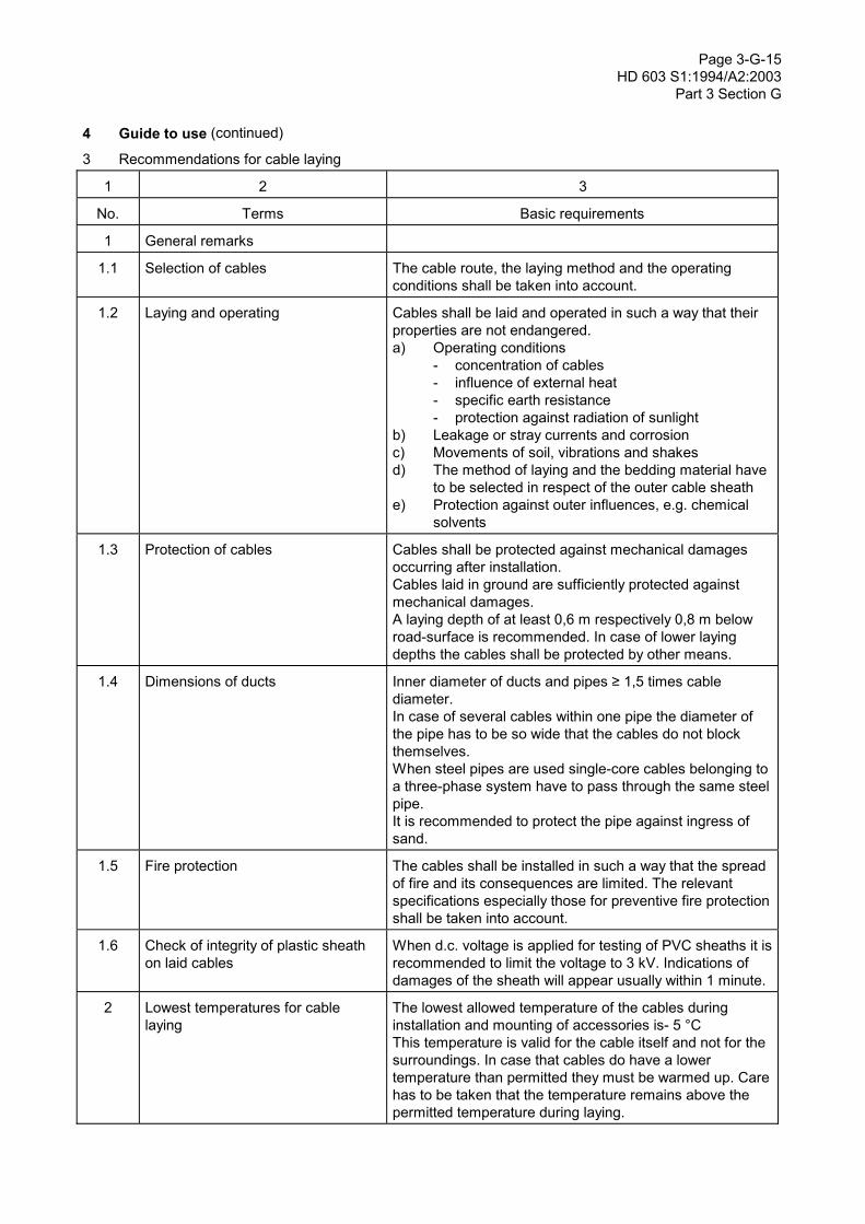
Page 3-G-15 HD 603 S1:1994/A2:2003
Part 3 Section G
4 Guide to use (continued) 3 Recommendations for cable laying
1 2 3
No. Terms Basic requirements
1 General remarks
1.1 Selection of cables The cable route, the laying method and the operating conditions shall be taken into account.
1.2 Laying and operating Cables shall be laid and operated in such a way that their properties are not endangered. a) Operating conditions - concentration of cables - influence of external heat - specific earth resistance - protection against radiation of sunlight b) Leakage or stray currents and corrosion c) Movements of soil, vibrations and shakes d) The method of laying and the bedding material have to be selected in respect of the outer cable sheath e) Protection against outer influences, e.g. chemical solvents
1.3 Protection of cables Cables shall be protected against mechanical damages occurring after installation. Cables laid in ground are sufficiently protected against mechanical damages. A laying depth of at least 0,6 m respectively 0,8 m below road-surface is recommended. In case of lower laying depths the cables shall be protected by other means.
1.4 Dimensions of ducts Inner diameter of ducts and pipes ≥ 1,5 times cable diameter. In case of several cables within one pipe the diameter of the pipe has to be so wide that the cables do not block themselves. When steel pipes are used single-core cables belonging to a three-phase system have to pass through the same steel pipe. It is recommended to protect the pipe against ingress of sand.
1.5 Fire protection The cables shall be installed in such a way that the spread of fire and its consequences are limited. The relevant specifications especially those for preventive fire protection shall be taken into account.
1.6 Check of integrity of plastic sheath on laid cables
When d.c. voltage is applied for testing of PVC sheaths it is recommended to limit the voltage to 3 kV. Indications of damages of the sheath will appear usually within 1 minute.
2 Lowest temperatures for cable laying
The lowest allowed temperature of the cables during installation and mounting of accessories is- 5 °C This temperature is valid for the cable itself and not for the surroundings. In case that cables do have a lower temperature than permitted they must be warmed up. Care has to be taken that the temperature remains above the permitted temperature during laying.

Page 3-G-16 HD 603 S1:1994/A2:2003 Part 3 Section G
4 Guide to use (continued) 3 Recommendations for cable laying (continued)
1 2 3
No. Terms Basic requirements
3 Pulling loads
3.1 Pulling force a) Pulling head b) Pulling grip
Maximum pulling force P = S σ where cross-sectional area of conductor S in mm2 and permissible tensile stress σ = 50N/mm2 for cables with copper conductors σ = 30N/mm2 for cables with aluminium conductors With this pulling force it is guaranteed that the permitted elongation of 0,2 % for the conductor will not be exceeded.The maximum permissible pulling force (P in N) is calculated from the total of the nominal cross-sectional area. The nominal cross-sectional area of the screens and of the concentric conductors shall not be considered in this calculation. For the pulling of cables having no metallic sheath and no armouring the pulling force can be transmitted by a pulling grip via a frictional connection between the pulling grip and the conductor of the cable. Therefore the same pulling loads apply as for the pulling head.
3.2 Types of laying Cables may be dug in also by means of a plough or they may be laid by a flushing-in method.
3.3 Preparation of cable route It is assumed that the cable route is well designed for the laying procedure with well-established curves and a sufficient number of cable rollers. Special attention shall be paid to the required minimum bending radii (see Clause 4).The pulling force shall be permanently supervised during the pull-in procedure.
4 Bending radii a) Permissible bending radius b) Reduction of bending radius
During installation - single-core cables: 15 times the cable diameter - multi-core cables: 12 times the cable diameter By 50 % provided that - single-time bending - the work is made by skilled workers - the cable is heated up to 30 °C - the cable is bent by means of a template

Page 3-G-17 HD 603 S1:1994/A2:2003
Part 3 Section G
4 Guide to use (concluded) 3 Recommendations for cable laying (concluded)
1 2 3
No. Terms Basic requirements
5 Cable fixing Single-core cables may be laid alone or systemwise in bundles. A system of bundled cables may be treated as a multi-core cable. In case of separate laying of single-core cables, cleats made of plastics or cleats consisting of non-magnetic metals have to be used. Steel cleats may be used if the magnetic circuit is not closed. Cables and bundles of cables are to be tightened in such a way that damages in form of indentation marks by pressure caused by heat expansion are avoided.
5.1 Horizontal distance between cleats 20 times the cable diameter. This distance is also valid between points of support in case of laying on cable racks or inside cable trays. In any case a distance of 80 cm should not be exceeded.
5.2 Vertical distance between cleats For vertical cable laying on walls higher distance between the cleats is permitted. The distance of 1,5 m, however, should not be exceeded.
4 Recommendations for fault detection
1 2 3
No. Tests Basic requirements
1 2
Fault detection on a cable Fault detection on the sheath
- By d.c. voltage up to the relevant test voltage according to HD 603 -3G, Section 3, Clause 5, so far permanently connected equipment permits this - By impulse voltage up to d.c. test voltage (HD 603-3G, Section 3, Clause 5) When d.c. voltage is applied for fault location on PVC sheaths it is recommended to limit the voltage to 3 kV. Appropriate test procedures have to be chosen to prevent secondary damages of the cable, e.g. by the energy content of impulse waves.

Page 3-G-18 HD 603 S1:1994/A2:2003 Part 3 Section G
5 Current-carrying capacity (recommended values)
1 2 3 4
No. Terms Requirements Table, quantity
1 General This section applies to the current-carrying capacity under both standard and deviating provisions provided that the cables are in three-phase operation with three conductors loaded or one single-core cable in d.c.-operation
2 2.1 2.2 2.3 2.4
Temperatures Bonding Frequency Operating conditions
Basic provisions Maximum permissible operating temperature Maximum short-circuit temperature for Sn ≤ 300 mm2 Maximum short-circuit temperature for Sn > 300 mm2 Concentric conductors bonded at both ends Power frequency The tabulated rated current-carrying capacities are based on standard provisions such as: - operating mode - laying conditions - environmental conditions For deviating operating conditions the current-carrying capacities in the tables are to be multiplied by appropriate conversion factors 1) which shall be based on the same calculation method and operating conditions as used for the current-carrying capacity given in this clause.
70 °C 160 °C 140 °C 50 Hz See Appendix Tables 14, 15
3 3.1 3.1.1 3.1.2 3.1.3
Operating mode Laying conditions Environmental conditions
Cables in earth Rated current-carrying capacity Ir under standard provisions Cyclic load load factor (Definition of load factor, see Appendix, Table 16) Laying depth One multicore cable laid single. Three single-core cables in close trefoil formation laid throughout the cable length with one system only. Ambient temperature, soil Soil thermal resistivity, dried-out soil Soil thermal resistivity, moist soil
See Appendix, Table 14 0,7 0,7 m 20 °C 2,5 K.m/W 1,0 K.m/W
3.2 3.2.1 3.2.2 3.2.3
Operating mode Laying conditions Environmental conditions
Current-carrying capacity under deviating provisions 1) Load factor ⇒ factors f1 x f2 Laying depth Grouping of cables ⇒ factors f1 x f2 Ambient temperature ⇒ factors f1 x f2 Soil thermal resistivity, moist soil ⇒ factors f1 x f2
0,5... 1 0,7... 1.2 m 5 °C... 40 °C 0,7.. 2,5 K.m/W
1) To be agreed between purchaser and producer.

Page 3-G-19 HD 603 S1:1994/A2:2003
Part 3 Section G
5 Current-carrying capacity (concluded)
1 2 3 4
No. Terms Requirements Table, quantity
4 4.1 4.1.1 4.1.2 4.1.3 4.2 4.2.1 4.2.2 4.2.3
Operating mode Laying conditions Environmental conditions Operating mode Laying conditions Environmental conditions
Cables in air Rated current-carrying capacity Ir under standard provisions Continuous operation, load factor Free in air One multicore cable laid single. Three single-core cables laid throughout the cable length in close trefoil formation with one system only. protection against direct thermal radiation due to sun etc. Ambient temperature, air Current-carrying capacity under deviating provisions 1) -- Grouping of cables on trays and ladders Ambient temperature, air
See Appendix, Table 15 1,0 30 °C -- 10 °C... 50 °C
5 5.1 5.2 5.3
Rated short-circuit current (thermal) Permissible short-circuit current (thermal) Permissible short-circuit current (dynamic)
Short-circuit During a short-circuit cables are loaded thermally and mechanically as well. Therefore the nominal cross-sectional area Sn, the cable type and if necessary the fixing of cables are to be selected carefully such that the cables are not overloaded. The following provisions are valid for a short-circuit duration up to 5 s. The rated short-circuit current for a short-circuit duration of 1 s is calculated by multiplying the rated short-time current density with the nominal cross-sectional area of the conductor. For short-circuit durations deviating from 1 s the permissible short-circuit current is to be calculated by dividing the rated short-circuit current with the square root of the short-circuit duration (in s). For multicore cables special measures are not required up to 40 kA (peak value). Single-core cables shall be safety fixed to withstand the effects of peak short-circuit currents.
See Appendix, Table 17
1) To be agreed between purchaser and producer.
.
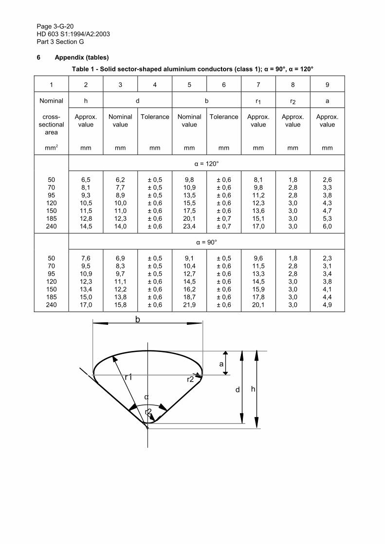
Page 3-G-20 HD 603 S1:1994/A2:2003 Part 3 Section G
6 Appendix (tables)
Table 1 - Solid sector-shaped aluminium conductors (class 1); α = 90°, α = 120°
1 2 3 4 5 6 7 8 9
Nominal h d b r1 r2 a
cross-sectional
area
Approx. value
Nominal value
Tolerance Nominal value
Tolerance Approx. value
Approx. value
Approx. value
mm2 mm mm mm mm mm mm mm mm
α = 120°
50 70 95 120 150 185 240
6,5 8,1 9,3 10,5 11,5 12,8 14,5
6,2 7,7 8,9 10,0 11,0 12,3 14,0
± 0,5 ± 0,5 ± 0,5 ± 0,6 ± 0,6 ± 0,6 ± 0,6
9,8 10,9 13,5 15,5 17,5 20,1 23,4
± 0,6 ± 0,6 ± 0,6 ± 0,6 ± 0,6 ± 0,7 ± 0,7
8,1 9,8 11,2 12,3 13,6 15,1 17,0
1,8 2,8 2,8 3,0 3,0 3,0 3,0
2,6 3,3 3,8 4,3 4,7 5,3 6,0
α = 90°
50 70 95 120 150 185 240
7,6 9,5 10,9 12,3 13,4 15,0 17,0
6,9 8,3 9,7 11,1 12,2 13,8 15,8
± 0,5 ± 0,5 ± 0,5 ± 0,6 ± 0,6 ± 0,6 ± 0,6
9,1 10,4 12,7 14,5 16,2 18,7 21,9
± 0,5 ± 0,6 ± 0,6 ± 0,6 ± 0,6 ± 0,6 ± 0,6
9,6 11,5 13,3 14,5 15,9 17,8 20,1
1,8 2,8 2,8 3,0 3,0 3,0 3,0
2,3 3,1 3,4 3,8 4,1 4,4 4,9
b
hα
r2
r2
r1d
a

Page 3-G-21 HD 603 S1:1994/A2:2003
Part 3 Section G
6 Appendix (tables) (continued)
Table 2 Stranded sector-shaped aluminium or copper conductors (class 2); α = 90°, α = 120°
1 2 3 4 5 6 7 8
Nominal h d b r1 r2 a
cross-sectional area
Approx. value
Nominal value
Tolerance Nominal value
Approx. value
Approx. value
Approx. value
mm2 mm mm mm mm mm mm mm
Α = 120°
35 1) 50 70 95 120 150 185 240
300 1)
6,1 7,1 8,6 10,0 11,2 12,6 14,0 16,0 17,8
5,9 6,8 8,2 9,6 10,8 12,2 13,6 15,6 17,4
± 0,7 ± 0,7 ± 0,7 ± 0,7 ± 0,8 ± 0,8 ± 0,8 ± 0,8 ± 0,8
9,5 10,9 13,1 15,6 17,7 20,3 23,1 26,7 29,5
7,5 8,7 10,3 12,0 13,0 14,6 16,0 18,2 20,5
1,5 1,8 2,3 2,4 2,4 2,5 2,5 2,6 2,9
2,5 2,9 3,5 4,1 4,7 5,3 5,9 6,8 7,6
α = 90°
35 1) 50 70 95 120 150 185 240
300 1)
7,2 8,3 10,0 11,7 13,2 14,6 16,2 18,6 20,6
6,5 7,6 9,0 10,7 12,1 13,5 15,1 17,4 19,4
± 0,7 ± 0,7 ± 0,7 ± 0,8 ± 0,8 ± 0,8 ± 0,8 ± 0,8 ± 0,8
8,9 10,4 12,1 14,7 16,4 18,4 20,8 24,3 27,3
9,0 10,3 12,3 14,1 15,5 17,2 19,0 21,6 24,0
1,6 1,7 2,3 2,3 2,7 2,7 2,7 2,8 2,8
2,1 2,4 3,0 3,4 3,9 4,3 4,7 5,3 5,8
1) Copper conductors only.
h
α
r2
r2
r1
d
a
b

Page 3-G-22 HD 603 S1:1994/A2:2003 Part 3 Section G
6 Appendix (tables; continued)
Table 3 - Stranded sector-shaped aluminium or copper conductors (class 2); α = 60°, α = 100°
1 2 3 4 5 6 7 8
Nominal h d b r1 r2 a
cross-sectional area
Approx. value
Nominal value
Tolerance Nominal value
Approx. value
Approx. value
Approx. value
mm2 mm mm mm mm mm mm mm
α = 100°
50 70 95 120 150 185 240
300 1)
8,1 9,5 11,2 12,5 14,0 15,5 17,8 20,0
7,6 8,8 10,5 11,6 13,2 14,6 16,9 19,2
± 0,7 ± 0,7 ± 0,8 ± 0,8 ± 0,8 ± 0,8 ± 0,8 ± 0,8
11,0 12,5 15,3 17,0 19,4 22,0 25,5 29,1
9,9 11,3 13,3 14,6 16,3 18,1 20,7 23,1
1,7 2,3 2,3 2,7 2,7 2,7 2,8 2,8
2,7 3,2 3,7 4,1 4,6 5,0 5,8 6,5
α = 60°
35 1) 50 70 95 120 150 185
9,2 10,9 13,2 15,2 17,0 19,0 20,5
7,6 9,2 10,9 12,9 14,3 16,3 17,8
± 0,7 ± 0,7 ± 0,8 ± 0,8 ± 0,8 ± 0,8 ± 0,8
7,9 9,6 11,4 13,5 14,9 16,9 18,7
11,3 13,3 16,3 18,1 20,7 23,1 26,5
1,6 1,7 2,3 2,3 2,7 2,7 2,7
1,9 2,1 2,7 2,9 3,4 3,6 3,6
1) Copper conductors only.
h
α
r2
r2
r1
d
a
b

Page 3-G-23 HD 603 S1:1994/A2:2003
Part 3 Section G
6 Appendix (tables) (continued)
Table 4 - Permissible conductor types
1 2
Type of conductor Range of cross-sectional area
Copper mm2
Aluminium mm2
Circular, solid Circular, stranded
Shaped, solid Shaped, stranded
1,5 to 16 1,5 to 500 1)
-- 35 to 300
25 to 50 50 to 630 1) 50 to 240 50 to 240
1) For single-core cables up to and including 1 000 mm².
Table 5 - Allocation of conductors with a reduced cross-sectional area
Nominal cross-sectional area of the phase conductors
mm²
Nominal cross-sectional area of the conductor with a reduced cross-sectional area
mm²
25 35 50 70 95 120 150 185 240 300 400 500
16 16 25 35 50 70 70 95 120 150 185 240

Page 3-G-24 HD 603 S1:1994/A2:2003 Part 3 Section G
6 Appendix (tables) (continued)
Table 6 - Core identification in multi-core cables by colours 3) 4)
1 2 3 4
Number of cores With green-yellow marked core
Without green-yellow marked core
With concentric conductor
2 green-yellow black 1)
acc. to HD 308 acc. to HD 308
3 acc. to HD 308 acc. to HD 308 acc. to HD 308
4 acc. to HD 308 2) acc. to HD 3082) acc. to HD 308
5 2) acc. to HD 308 2) acc. to HD 308 2)
1) This two-core design is only permissible for conductor cross-sectional area equal or greater than 10 mm2 copper or 16 mm2 aluminium. 2) Where cables have a core with a reduced conductor cross section, this core shall be marked green-yellow in designs according to column 2 and blue in designs according to column 3. 3) If the core is marked on the surface only, the insulation under the surface shall have no colour additives, except in the case of a two-coloured identification. The specified colours shall correspond to HD 402. Precise compliance of the colours can be impeded by various influences (for example the type of material, running colour of material, texture of the surface, manufacturing methods, interference by adjacent colours, etc.). Therefore deviations from the specified colour are permissible, as long as the colours cannot be confused with another colour in daylight or artificial lighting. 4) The sequence of colours as given in the table shall be observed.

Page 3-G-25 HD 603 S1:1994/A2:2003
Part 3 Section G
6 Appendix (tables) (continued)
Table 7 - Thickness of the extruded inner covering
1 2 3
Fictitious diameter over the laid-up cores
mm
Thickness of the extruded inner covering (approx. value)
mm
Minimum thickness
mm
up to 25 over 25 to 35 over 35 to 45 over 45 to 60 over 60 to 80
over 80
1,0 1,2 1,4 1,6 1,8 2,0
0,5 0,6 0,7 0,8 0,9 1,0
Table 8 - Number, minimum cross-sectional areas and maximum distances between windings of copper binder tapes
1 2 3 4
Diameter D 1) under screen or concentric
conductor
Number of copper binder tapes
Minimum cross-sectional area of each copper
binder tape
Maximum distance 2) between windings of copper binder tapes
up to 15 mm 1 2
0,5 mm2 0,5 mm2
4 D 4 D
over 15 mm 1 2
1,0 mm2 0,5 mm2
4 D 2 D
1) D is the fictitious diameter under the screen or concentric conductor according to IEC 60502-1, Annex A. 2) Clearance between two adjacent windings in the longitudinal direction of the cable.
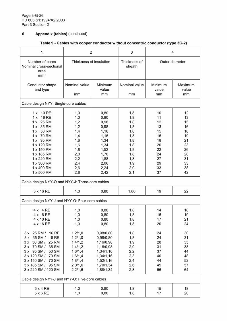
Page 3-G-26 HD 603 S1:1994/A2:2003 Part 3 Section G
6 Appendix (tables) (continued)
Table 9 - Cables with copper conductor without concentric conductor (type 3G-2)
1 2 3 4
Number of cores Nominal cross-sectional
area mm2
Thickness of insulation Thickness of sheath
Outer diameter
Conductor shape and type
Nominal value
mm
Minimum value mm
Nominal value
mm
Minimum value mm
Maximum value mm
Cable design NYY: Single-core cables
1 x 10 RE 1 x 16 RE 1 x 25 RM 1 x 35 RM 1 x 50 RM 1 x 70 RM 1 x 95 RM 1 x 120 RM 1 x 150 RM 1 x 185 RM 1 x 240 RM 1 x 300 RM 1 x 400 RM 1 x 500 RM
1,0 1,0 1,2 1,2 1,4 1,4 1,6 1,6 1,8 2,0 2,2 2,4 2,6 2,8
0,80 0,80 0,98 0,98 1,16 1,16 1,34 1,34 1,52 1,70 1,88 2,06 2,24 2,42
1,8 1,8 1,8 1,8 1,8 1,8 1,8 1,8 1,8 1,8 1,8 1,9 2,0 2,1
10 11 12 13 15 16 18 20 22 24 27 29 33 37
12 13 15 16 18 19 21 23 26 28 31 33 38 42
Cable design NYY-O and NYY-J: Three-core cables
3 x 16 RE 1,0 0,80 1,80 19 22
Cable design NYY-J and NYY-O: Four-core cables
4 x 4 RE 4 x 6 RE 4 x 10 RE 4 x 16 RE
3 x 25 RM / 16 RE 3 x 35 SM / 16 RE 3 x 50 SM / 25 RM 3 x 70 SM / 35 SM 3 x 95 SM / 50 SM 3 x 120 SM / 70 SM 3 x 150 SM / 70 SM 3 x 185 SM / 95 SM 3 x 240 SM / 120 SM
1,0 1,0 1,0 1,0
1,2/1,0 1,2/1,0 1,4/1,2 1,4/1,2 1,6/1,4 1,6/1,4 1,8/1,4 2,0/1,6 2,2/1,6
0,80 0,80 0,80 0,80
0,98/0,80 0,98/0,80 1,16/0,98 1,16/0,98 1,34/1,16 1,34/1,16 1,52/1,16 1,70/1,34 1,88/1,34
1,8 1,8 1,8 1,8
1,8 1,8 1,9 2,0 2,2 2,3 2,4 2,6 2,8
14 15 17 20
24 24 28 31 37 40 44 49 56
18 19 21 24
30 31 35 38 44 48 52 57 64
Cable design NYY-J and NYY-O: Five-core cables
5 x 4 RE 5 x 6 RE
1,0 1,0
0,80 0,80
1,8 1,8
15 17
18 20

Page 3-G-27 HD 603 S1:1994/A2:2003
Part 3 Section G
6 Appendix (tables) (continued)
Table 10 - Cables with copper conductor with concentric conductor (type 3G-1)
1 2 3 4
Number of cores Nominal cross-sectional
area mm2
Thickness of insulation Thickness of sheath
Outer diameter
Conductor shape and type
Nominal value
mm
Minimum value mm
Nominal value
mm
Minimum value mm
Maximum value mm
Cable design NYCY and NYCWY: Three-core cables
3 x 4 RE / 4 3 x 6 RE / 6
3 x 10 RE / 10 3 x 16 RE / 16 3 x 25 RM / 25 3 x 25 RM / 16 3 x 35 RM / 35 3 x 35 RM / 16 3 x 35 SM / 35 3 x 35 SM / 16 3 x 50 SM / 50 3 x 50 SM / 25 3 x 70 SM / 70 3 x 70 SM / 35 3 x 95 SM / 95 3 x 95 SM / 50 3 x 120 SM / 120 3 x 120 SM / 70 3 x 150 SM / 150 3 x 150 SM / 70 3 x 185 SM / 95 3 x 240 SM / 120
1,0 1,0
1,0 1,0 1,2 1,2 1,2 1,2 1,2 1,2 1,4 1,4 1,4 1,4 1,6 1,6 1,6 1,6 1,8 1,8 2,0 2,2
0,80 0,80
0,80 0,80 0,98 0,98 0,98 0,98 0,98 0,98 1,16 1,16 1,16 1,16 1,34 1,34 1,34 1,34 1,52 1,52 1,70 1,88
1,8 1,8
1,8 1,8 1,8 1,8 1,8 1,8 1,8 1,8 1,9 1,9 2,0 2,0 2,2 2,2 2,3 2,3 2,4 2,4 2,6 2,8
15 16
19 21 25 25 27 27 25 25 28 28 33 32 37 37 41 40 45 44 49 56
19 20
23 25 31 31 33 33 32 32 35 35 40 39 44 44 48 47 52 51 56 63
Cable design NYCY and NYCWY: Four-core cables
4 x 4 RE / 4 4 x 4 RE / 6
4 x 10 RE / 10 4 x 16 RE / 16 4 x 25 RM / 16 4 x 35 SM / 16 4 x 50 SM / 25 4 x 70 SM / 35 4 x 95 SM / 50 4 x 120 SM / 70 4 x 150 SM / 70
1,0 1,0
1,0 1,0 1,2 1,2 1,4 1,4 1,6 1,6 1,8
0,80 0,80
0,80 0,80 0,98 0,98 1,16 1,16 1,34 1,34 1,52
1,8 1,8
,8 1,8 1,8 1,8 2,0 2,1 2,3 2,4 2,6
16 17
20 23 27 28 32 36 42 46 50
20 21
24 27 34 35 39 43 49 53 57

Page 3-G-28 HD 603 S1:1994/A2:2003 Part 3 Section G
6 Appendix (tables) (continued)
Table 11 - Cables with aluminium conductors without concentric conductor (type 3G-2) with concentric conductor (type 3G-1)
1 2 3 4
Number of cores Nominal cross-sectional
area mm2
Thickness of insulation Thickness of sheath
Outer diameter
Conductor shape and type
Nominal value
mm
Minimum value mm
Nominal value
mm
Minimum value mm
Maximum value mm
Cables design NAYY-O and NAYY-J: Four-core cables
4 x 25 RE 4 x 35 RE 4 x 50 RE 4 x 50 SE 4 x 70 SE 4 x 95 SE 4 x 120 SE 4 x 150 SE 4 x 185 SE
1,2 1,2 1,4 1,4 1,4 1,6 1,6 1,8 2,0
0,98 0,98 1,16 1,16 1,16 1,34 1,34 1,52 1,70
1,8 1,8 1,9 1,9 2,1 2,2 2,4 2,5 2,7
24 27 31 28 33 37 41 44 49
28 31 35 33 38 42 46 49 54
Cable design NAYCWY: Three-core cables with concentric conductor
3 x 25 RE / 25 3 x 35 RE / 35 3 x 50 SE / 50 3 x 70 SE / 70 3 x 95 SE / 95 3 x 120 SE / 120 3 x 150 SE / 150 3 x 185 SE / 185
1,2 1,2 1,4 1,4 1,6 1,6 1,8 2,0
0,98 0,98 1,16 1,16 1,34 1,34 1,52 1,70
1,8 1,8 1,9 2,0 2,2 2,3 2,4 2,6
24 26 27 31 35 38 42 47
28 31 33 37 42 45 49 54

Page 3-G-29 HD 603 S1:1994/A2:2003
Part 3 Section G
6 Appendix (tables) (continued)
Table 12 - Type designations (provisional) Cables are designated with:
- abbreviated code description of the cable design,
N A
Y C
CW Y
-J -O
Cable according to this specification Aluminium conductor Copper conductor (no abbreviation) PVC insulation Concentric conductor (helically) Concentric conductor (wave form) PVC sheath With green-yellow core Without green-yellow core
- number of cores by nominal cross-sectional area of conductor in mm2, - indications of shape type of conductor,
R S E M
Circular conductor Sector-shaped conductor Solid conductor Stranded conductor
- where applicable nominal cross-sectional area of screen or concentric conductor in mm2, - rated voltage in kV.
Table 13 - Barrel diameter of delivery drums
Cable type
Barrel diameter of cable drum 1)
Cables without concentric conductor - single-core - multi-core S ≤ 95 mm2 - multi-core S > 95 mm2 Cables with concentric conductor
18 d 15 d 18 d
20 d
d S 1)
- Outer diameter of the cable: maximum value according to Tables 9 to 11 or manufacturer's values. - Nominal cross sectional area of insulated conductor. - There is no direct relationship between the barrel diameter of the cable drum, according to this table and the permissible radius, given in Section 4, Clause 3, item 4, for cable laying because the stresses (loads) are completely different.

Page 3-G-30 HD 603 S1:1994/A2:2003 Part 3 Section G
6 Appendix (tables) (continued)
Table 14 - Rated current-carrying capacity, cables in earth (recommended values)
1 2 3 4 5 6 7 8 9 10 11 Insulating material
PVC
Permissible operating temperature
70 °C
Designation NYY NYCWY; NYCY NAYY NAYCWY; NAYCY
Arrangement 1)
1)
Number of loaded conductors
1
3
3
3
3
1
3
3
3
3
Cross-sectional area in mm2
Copper conductor Rated current in A
Aluminium conductor Rated current in A
1,5 2,5 4 6 10 16 25 35 50 70 95 120 150 185 240 300 400 500 630 800 1000
41 55 71 90 124 160 208 250 296 365 438 501 563 639 746 848 975 1125 1304 1507 1715
27 36 47 59 79 102 133 159 188 232 280 318 359 406 473 535 613 687 - - -
30 39 50 62 83 107 138 164 195 238 325 365 413 479 541 614 693 777 859 936
27 36 47 59 79 102 133 160 190 234 280 319 357 402 463 518 579 624 - - -
31 40 51 63 84 108 139 166 196 238 281 315 347 385 432 473 521 574 636 - -
- - - - - - 160 193 230 283 340 389 436 496 578 656 756 873 1011 1166 1332
- - - - - - 102 123 144 179 215 245 275 313 364 419 484 553 - - -
- - - - - - 106 127 151 185 222 253 284 322 375 425 487 558 635 716 796
- - - - - - 103 123 145 180 216 246 276 313 362 415 474 528 - - -
- - - - - - 108 129 153 187 223 252 280 314 358 397 441 489 539 - -
1) Rated current for cables in d.c. systems with return conductor far away.
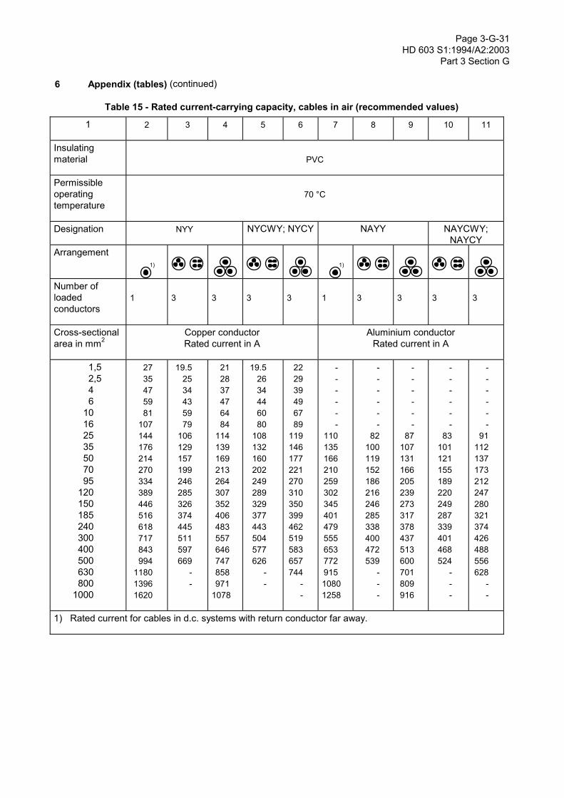
Page 3-G-31 HD 603 S1:1994/A2:2003
Part 3 Section G
6 Appendix (tables) (continued)
Table 15 - Rated current-carrying capacity, cables in air (recommended values)
1 2 3 4 5 6 7 8 9 10 11
Insulating material
PVC
Permissible operating temperature
70 °C
Designation NYY NYCWY; NYCY NAYY NAYCWY; NAYCY
Arrangement 1)
1)
Number of loaded conductors
1
3
3
3
3
1
3
3
3
3
Cross-sectional area in mm2
Copper conductor Rated current in A
Aluminium conductor Rated current in A
1,5 2,5 4 6 10 16 25 35 50 70 95 120 150 185 240 300 400 500 630 800 1000
27 35 47 59 81 107 144 176 214 270 334 389 446 516 618 717 843 994 1180 1396 1620
19.5 25 34 43 59 79 106 129 157 199 246 285 326 374 445 511 597 669 - -
21 28 37 47 64 84 114 139 169 213 264 307 352 406 483 557 646 747 858 971 1078
19.5 26 34 44 60 80 108 132 160 202 249 289 329 377 443 504 577 626 - -
22 29 39 49 67 89 119 146 177 221 270 310 350 399 462 519 583 657 744 - -
- - - - - - 110 135 166 210 259 302 345 401 479 555 653 772 915 1080 1258
- - - - - - 82 100 119 152 186 216 246 285 338 400 472 539 - - -
- - - - - - 87 107 131 166 205 239 273 317 378 437 513 600 701 809 916
- - - - - - 83 101 121 155 189 220 249 287 339 401 468 524 - - -
- - - - - - 91 112 137 173 212 247 280 321 374 426 488 556 628 - -
1) Rated current for cables in d.c. systems with return conductor far away.
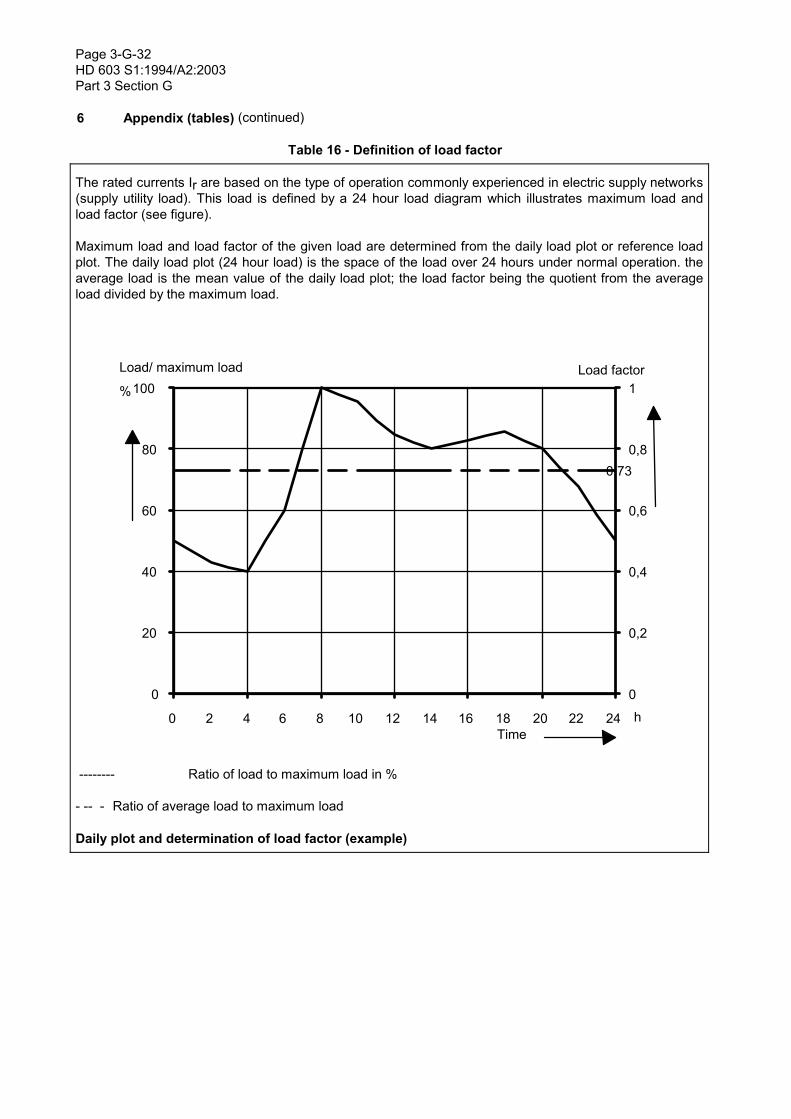
Page 3-G-32 HD 603 S1:1994/A2:2003 Part 3 Section G
6 Appendix (tables) (continued)
Table 16 - Definition of load factor
The rated currents Ir are based on the type of operation commonly experienced in electric supply networks (supply utility load). This load is defined by a 24 hour load diagram which illustrates maximum load and load factor (see figure).
Maximum load and load factor of the given load are determined from the daily load plot or reference load plot. The daily load plot (24 hour load) is the space of the load over 24 hours under normal operation. the average load is the mean value of the daily load plot; the load factor being the quotient from the average load divided by the maximum load.
0
20
40
60
80
100
0 2 4 6 8 10 12 14 16 18 20 22 24
0
0,2
0,4
0,6
0,8
1
0,73
Load/ maximum load
%Load factor
Timeh
-------- Ratio of load to maximum load in %
- -- - Ratio of average load to maximum load
Daily plot and determination of load factor (example)

Page 3-G-33 HD 603 S1:1994/A2:2003
Part 3 Section G
6 Appendix (tables) (concluded)
Table 17 - Permissible short-circuit temperatures and rated short-time current densities
1 2 3 4 5 6 7 8
Cables with Permissible short-circuit temperature in °C
Conductor temperature at the beginning of short-circuit in °C
70 60 50 40 30 20
Rated short-time current density in A/mm² for a rated short-circuit duration of 1 s
Copper conductors ≤ 300 mm² > 300 mm²
160 140
115 103
122 111
129 118
136 126
143 133
150 140
Aluminium conductors ≤ 300 mm² > 300 mm²
160 140
76 68
81 73
85 78
90 83
95 88
99 93

Page 3-G-34 HD 603 S1:1994/A2:2003 Part 3 Section G
BLANK PAGE

Page 3-I-0 HD 603 S1:1994/A2:2003
Part 3 Section I
SECTION 3-I - CABLES WITH (TYPE 3I-1) AND WITHOUT (TYPES 3I-2 AND 3I-3) CONCENTRIC CONDUCTOR
Replace Section 3-I
by the following A2 referred new Section 3-I:


Page 3-I-1 HD 603 S1:1994/A2:2003
Part 3 Section I
SECTION 3-I - CABLES WITH (TYPE 3I-1) AND WITHOUT (TYPES 3I-2 AND 3I-3) CONCENTRIC CONDUCTOR

Page 3-I-2 HD 603 S1:1994/A2:2003 Part 3 Section I
CONTENTS
1 General -----------------------------------------------------------------------------------------------------------4
2 Design requirements -------------------------------------------------------------------------------------------------5
1 Conductor -----------------------------------------------------------------------------------------------------5 1.1 Material 1.2 Main conductors 1.3 Mechanical properties of aluminium conductors 1.4 Auxiliary conductors 1.5 Conductor resistance 1.6 Permissible conductor types 1.7 Dimensions of sector-shaped conductors
2 Insulation ------------------------------------------------------------------------------------------------------5 2.1 Material 2.2 Insulation thickness 2.3 Core identification
3 Assembly of cores and fillers -----------------------------------------------------------------------------6 3.1 Assembly of cores 3.2 Fillers
4 Inner covering ------------------------------------------------------------------------------------------------6 4.1 Material 4.2 Thickness
5 Innersheath ---------------------------------------------------------------------------------------------------6 5.1 Material 5.2 Thickness 5.3 Colour
6 Concentric Conductor --------------------------------------------------------------------------------------7 6.1 Design 6.2 Cross section 6.3 DC Resistance 6.4 Dimensions
7 Outer sheath--------------------------------------------------------------------------------------------------8 7.1 Material 7.2 Thickness 7.3 Colour
8 Marking --------------------------------------------------------------------------------------------------------8 8.1 Indication of origin 8.2 Year of manufacture 8.3 Code designation 8.4 Continuity of marks 8.5 Durability 8.6 Legibility 8.7 Meter marking
9 Code designation--------------------------------------------------------------------------------------------8
3 Test requirements ----------------------------------------------------------------------------------------------------9 1 Routine tests -----------------------------------------------------------------------------------------9 2 Sample tests---------------------------------------------------------------------------------------- 10 3 Type tests, electrical------------------------------------------------------------------------------ 13 4 Type tests, non-electrical------------------------------------------------------------------------ 14
4 Appendix (tables and Guide to use) ---------------------------------------------------------------------------- 16

Page 3-I-3 HD 603 S1:1994/A2:2003
Part 3 Section I
REFERENCES References are made in Section 3-I of HD 603, to other parts of this HD and to other Harmonization Documents and International Standards as follows:
HD 383 Conductors of insulated cables First supplement: Guide to the dimensional limits of circular conductors (endorsing IEC 60228 and 60228A)
HD 605 Electric cables Additional test methods
EN 50265 (series) Common test methods for cables under fire conditions Test for resistance to vertical flame propagation for a single insulated conductor or cable
EN 60811 (series) Insulating and sheathing materials of electric cables Common test methods
In all cases reference to another HD or International Standard implies the latest edition of that document.

Page 3-I-4 HD 603 S1:1994/A2:2003 Part 3 Section I
1 General
This standard specifies the construction, dimensions and test requirements of power cables with PVC-insulation, with or without concentric conductor and with PVC-sheath for rated voltage (U) of 1 kV for fixed installations. Both cable types may be provided with auxiliary cores
(a) Insulating materials
The insulation covered by this standard shall consist of polyvinyl chloride and correspond to Table 1 of HD 603-1, type DIV 8.
(b) Rated voltage
0,6/1 kV
Definitions: see HD 603-1, Subclause 2.3
(c) Highest rated temperature for the insulating compound
(i) Normal operation 70 °C
(d) Sheathing material
Shall be suitable for the maximum rated conductor temperature. It shall consist of PVC and correspond to Table 4A of HD 603-1, type DMV 14.
(e) Test requirements
Type test (symbol T): validity of a type test is 5 years.
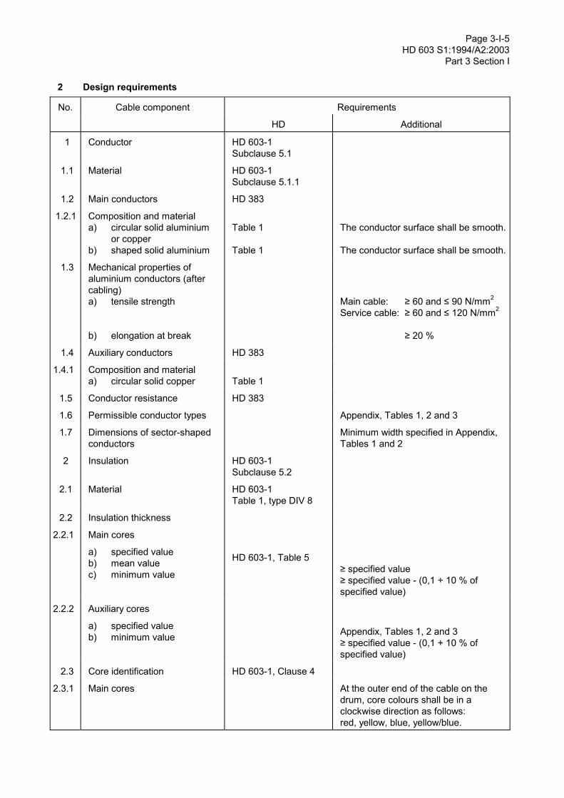
Page 3-I-5 HD 603 S1:1994/A2:2003
Part 3 Section I
2 Design requirements
No. Cable component Requirements
HD Additional
1 Conductor HD 603-1 Subclause 5.1
1.1 Material HD 603-1 Subclause 5.1.1
1.2 Main conductors HD 383
1.2.1 Composition and material a) circular solid aluminium or copper b) shaped solid aluminium
Table 1 Table 1
The conductor surface shall be smooth. The conductor surface shall be smooth.
1.3 Mechanical properties of aluminium conductors (after cabling) a) tensile strength b) elongation at break
Main cable: ≥ 60 and ≤ 90 N/mm2 Service cable: ≥ 60 and ≤ 120 N/mm2 ≥ 20 %
1.4 Auxiliary conductors HD 383
1.4.1 Composition and material a) circular solid copper
Table 1
1.5 Conductor resistance HD 383
1.6 Permissible conductor types Appendix, Tables 1, 2 and 3
1.7 Dimensions of sector-shaped conductors
Minimum width specified in Appendix, Tables 1 and 2
2 Insulation HD 603-1 Subclause 5.2
2.1 Material HD 603-1 Table 1, type DIV 8
2.2 Insulation thickness
2.2.1 Main cores
a) specified value b) mean value c) minimum value
HD 603-1, Table 5
≥ specified value ≥ specified value - (0,1 + 10 % of specified value)
2.2.2 Auxiliary cores
a) specified value b) minimum value
Appendix, Tables 1, 2 and 3 ≥ specified value - (0,1 + 10 % of specified value)
2.3 Core identification HD 603-1, Clause 4
2.3.1 Main cores At the outer end of the cable on the drum, core colours shall be in a clockwise direction as follows: red, yellow, blue, yellow/blue.

Page 3-I-6 HD 603 S1:1994/A2:2003 Part 3 Section I
2 Design requirements (continued)
No. Cable component Requirements
HD Additional
2.3.2 Auxiliary cores Colours shall be as follows: a) four aux. cores of equal cross- sectional area: same as main cores; b) two aux. cores: red, blue; c) four aux. cores, two groups of different cross-sectional area: - larger cross-sectional area: red, blue, - smaller cross-sectional area: yellow, yellow/blue.
Each auxiliary core at the outer end of the cable on the cable drum, is situated on the right hand side of the main core with the same colour.
2.3.3 Colour combination yellow/blue
The colour stripes shall be applied to the core in longitudinal direction. The distribution of the colours shall be such that each colour covers at least 20 % of the surface of the core. On any 50 mm length of the outer side of the twisted cores both colours shall be discernible.
3 Assembly of cores HD 603-1 Subclause 5.3
For main cable the approximate length of lay is 40 times the diameter over the core assembly with a minimum of 1,1 m. The main cores shall be laid up with a left hand direction of lay, auxiliary cores shall be laid in the interstices of the main cores.
4 Filler
4.1 Centre filler HD 603-1 Subclause 5.4
A centre filler shall of non hygroscopic material be applied.
4.2 Inner covering HD 603-1 Subclause 5.5
The inner covering shall be extruded and shall fill the interstices.
4.2.1 Thickness
Cables types 3I-2 and 3I-3 a) specified value b) mean value c) minimum value
Appendix, Tables 2 and 3 ≥ specified value ≥ 2,0 mm
4.2.2 Cables type 3I-1 Thickness not specified, if the nominal thickness is ≥ 1,0 mm the inner covering shall cover the assembled cores totally.
5 Innersheath for cables with concentric conductor (type 3I-1), if present
HD 603-1 Subclause 5.6
5.1 Material HD 603-1 Table 4A, type DMV 14

Page 3-I-7 HD 603 S1:1994/A2:2003
Part 3 Section I
2 Design requirements (continued)
No. Cable component Requirements
HD Additional
5.2 Thickness a) specified value b) mean value c) minimum value
Appendix Table 1 ≥ specified value ≥ specified value - (0,1 + 15 % of specified value)
5.3 Colour Black or grey
6 Concentric conductor
6.1 Design Copper wires with one or two copper tapes as counter helix applied as an S-shaped concentric conductor around the circumference of the innersheath, laid in a bedding of unvulcanised rubber.
The wavelength of the wave form shall be ≤ 240 mm. The amplitude shall be in such way, that removing the outer sheath over a length of 160 mm and dividing the copper wire in four bunches the distance between each bunch of wires and the innersheath is at least 35 mm over a length of 30 mm. The lay length of the counter helix shall be less than or equal to 4 times the mean diameter of the concentric conductor. When 2 tapes are used, the distance between them shall not exceed 2 times the mean diameter of the concentric conductor.
6.2 Cross-sectional area a) specified value b) minimum value
Appendix, Table 1 The geometrical cross-sectional area of the concentric conductor without the copper tapes shall be ≥ specified value.
In case of one counter helix the cross-sectional area shall be ≥ 1 mm². In the case of two counter helixes the cross-sectional area of each shall be ≥ 0,5 mm².
6.3 DC resistance HD 383
6.4 Dimensions The diameter of copper wires shall be: ≥ 1,0 mm and ≤ 1,4 mm. The thickness of the copper tape shall be: ≥ 0,1 mm and ≤ 0,3 mm.
The gaps between the copper wires shall be less than 4 mm, tolerance: maximum 5 % of the gaps, measured in one cross section, may have a wider gap but not more than 8 mm.

Page 3-I-8 HD 603 S1:1994/A2:2003 Part 3 Section I
2 Design requirements (continued)
No. Cable component Requirements
HD Additional
7 Outer sheath HD 603-1 Subclause 5.8
7.1 Material HD 603-1 Table 4A, type DMV 14
7.2 Thickness a) specified value b) mean value c) minimum value for types 3I-2 and 3I-3 for type 3I-1
Appendix Tables 1, 2 and 3 ≥ specified value ≥ specified value - (0,1 + 15 % of specified value) ≥ specified value - (0,3 + 15 % of specified value)
7.3 Colour Grey
8 Marking HD 603-1 Clause 3
Marking shall be applied by embossing or printing.
8.1 Indication of origin Manufacturers name or trademark on the sheath
8.2 Year of manufacture To be indicated on the sheath.
8.3 Code designation To be indicated on the sheath.
8.4 Continuity of marks (except meter marking)
Distance between the end of one set of marks and the beginning of the next ≤ 0,50 m
8.5 Durability HD 603-1 Subclause 3.3
8.6 Legibility HD 603-1 Subclause 3.4
8.7 Meter marking Either by a tape in the cable or by embossing or printing on the sheath
9 Code designation Examples (*):
9.1 Cables without concentric conductor (types 3I-2 and 3I-3)
a) cable without auxiliary cores VMvK/0,6/1 kV 4 x 50 Alsvm NEN 3616 b) cable with auxiliary cores VMvKh/0,6/1 kV 4 x 50 Alrm + 4 x 6 NEN 3616
c) cable without auxiliary cores VMvK/0,6/1 kV 4 x 16 Alrm NEN 3616 d) cable with auxiliary cores VMvKh/0,6/1 kV 4 x 16 Alrm + 4 x 1,5 NEN 3616
(*): Alsvm = shaped solid aluminium Alrm = circular solid aluminium

Page 3-I-9 HD 603 S1:1994/A2:2003
Part 3 Section I
2 Design requirements (concluded)
No. Cable component Requirements
HD Additional
Examples (*):
9.2 cld
Cables with concentric conductor (type 3I-1)
a) cable without auxiliaty cores V-VMvksas 0,6/1 kV 4 x 50 Alsvm + sas 25 NEN 3616 b) cable with auxiliary cores V-VMvksas 0,6/1 kV 4 x 50Alsvm + sas 25 NEN 3616 Alrm + 4 x 6 + sas 25 NEN 3616
(*): Alsvm = shaped solid aluminium Alrm = circular solid aluminium 3 Test requirements 1 Routine tests
1 2 3 4
No. Tests Requirements * Test methods
1 Conductor resistance Ref. no. 1.5
HD 605 Subclause 3.1.1
2 Resistance of concentric conductor
Ref. no. 6.3 HD 605 Subclause 3.1.1
3 High voltage test (on complete cable) ** - Test voltage - Duration of test - Test result
4 kV a.c. 5 min per core No breakdown
Four core cable without auxiliary cores: a) red and blue yellow, yellow/blue and earth b) yellow and yellow/blue red, blue and earth c) two adjacent cores remaining cores and earth
Four core cable with auxiliary cores: a) red and blue yellow, yellow/blue, all auxiliary cores and earth b) yellow and yellow/blue red, blue, all auxiliary cores and earth c) two adjacent cores and all auxiliary cores remaining cores and earth
4 Construction characteristics See Section 2 and HD 603-1, Clause 5
4.1 General construction of cable Visual inspection
4.2 Core identification Ref. no. 2.3
4.3 Marking Ref. no. 8 and HD 603-1, Clause 3
* According to Section 2 Design requirements unless stated otherwise. ** Concentric conductor or armour, if present, shall be connected to earth.
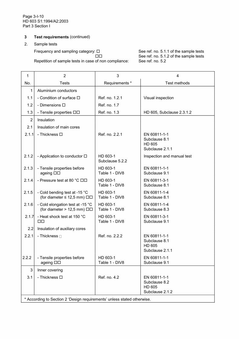
Page 3-I-10 HD 603 S1:1994/A2:2003 Part 3 Section I
3 Test requirements (continued) 2. Sample tests
Frequency and sampling category: See ref. no. 5.1.1 of the sample tests See ref. no. 5.1.2 of the sample tests Repetition of sample tests in case of non compliance: See ref. no. 5.2
1 2 3 4
No. Tests Requirements * Test methods
1 Aluminium conductors
1.1 - Condition of surface Ref. no. 1.2.1 Visual inspection
1.2 - Dimensions Ref. no. 1.7
1.3 - Tensile properties Ref. no. 1.3 HD 605, Subclause 2.3.1.2
2 Insulation
2.1 Insulation of main cores
2.1.1 - Thickness Ref. no. 2.2.1 EN 60811-1-1 Subclause 8.1 HD 605 Subclause 2.1.1
2.1.2 - Application to conductor HD 603-1 Subclause 5.2.2
Inspection and manual test
2.1.3 - Tensile properties before ageing
HD 603-1 Table 1 - DIV8
EN 60811-1-1 Subclause 9.1
2.1.4 - Pressure test at 80 °C HD 603-1 Table 1 - DIV8
EN 60811-3-1 Subclause 8.1
2.1.5 - Cold bending test at -15 °C (for diameter ≤ 12,5 mm)
HD 603-1 Table 1 - DIV8
EN 60811-1-4 Subclause 8.1
2.1.6 - Cold elongation test at -15 °C (for diameter > 12,5 mm)
HD 603-1 Table 1 - DIV8
EN 60811-1-4 Subclause 8.3
2.1.7 - Heat shock test at 150 °C
HD 603-1 Table 1 - DIV8
EN 60811-3-1 Subclause 9.1
2.2 Insulation of auxiliary cores
2.2.1 - Thickness Ref. no. 2.2.2 EN 60811-1-1 Subclause 8.1 HD 605 Subclause 2.1.1
2.2.2 - Tensile properties before ageing
HD 603-1 Table 1 - DIV8
EN 60811-1-1 Subclause 9.1
3 Inner covering
3.1 - Thickness Ref. no. 4.2 EN 60811-1-1 Subclause 8.2 HD 605 Subclause 2.1.2
* According to Section 2 Design requirements unless stated otherwise.
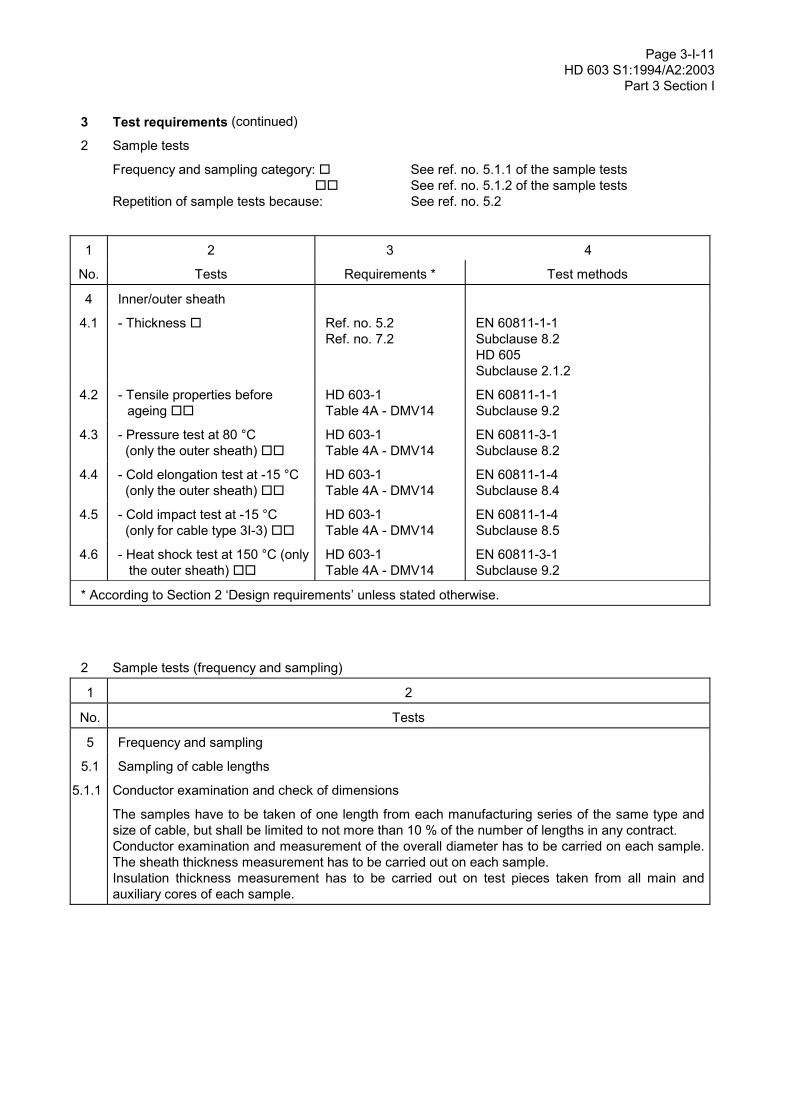
Page 3-I-11 HD 603 S1:1994/A2:2003
Part 3 Section I
3 Test requirements (continued) 2 Sample tests
Frequency and sampling category: See ref. no. 5.1.1 of the sample tests See ref. no. 5.1.2 of the sample tests Repetition of sample tests because: See ref. no. 5.2
1 2 3 4
No. Tests Requirements * Test methods
4 Inner/outer sheath
4.1 - Thickness Ref. no. 5.2 Ref. no. 7.2
EN 60811-1-1 Subclause 8.2 HD 605 Subclause 2.1.2
4.2 - Tensile properties before ageing
HD 603-1 Table 4A - DMV14
EN 60811-1-1 Subclause 9.2
4.3 - Pressure test at 80 °C (only the outer sheath)
HD 603-1 Table 4A - DMV14
EN 60811-3-1 Subclause 8.2
4.4 - Cold elongation test at -15 °C (only the outer sheath)
HD 603-1 Table 4A - DMV14
EN 60811-1-4 Subclause 8.4
4.5 - Cold impact test at -15 °C (only for cable type 3I-3)
HD 603-1 Table 4A - DMV14
EN 60811-1-4 Subclause 8.5
4.6 - Heat shock test at 150 °C (only the outer sheath)
HD 603-1 Table 4A - DMV14
EN 60811-3-1 Subclause 9.2
* According to Section 2 Design requirements unless stated otherwise.
2 Sample tests (frequency and sampling)
1 2
No. Tests
5 Frequency and sampling
5.1 Sampling of cable lengths
5.1.1 Conductor examination and check of dimensions
The samples have to be taken of one length from each manufacturing series of the same type and size of cable, but shall be limited to not more than 10 % of the number of lengths in any contract. Conductor examination and measurement of the overall diameter has to be carried on each sample.The sheath thickness measurement has to be carried out on each sample. Insulation thickness measurement has to be carried out on test pieces taken from all main and auxiliary cores of each sample.
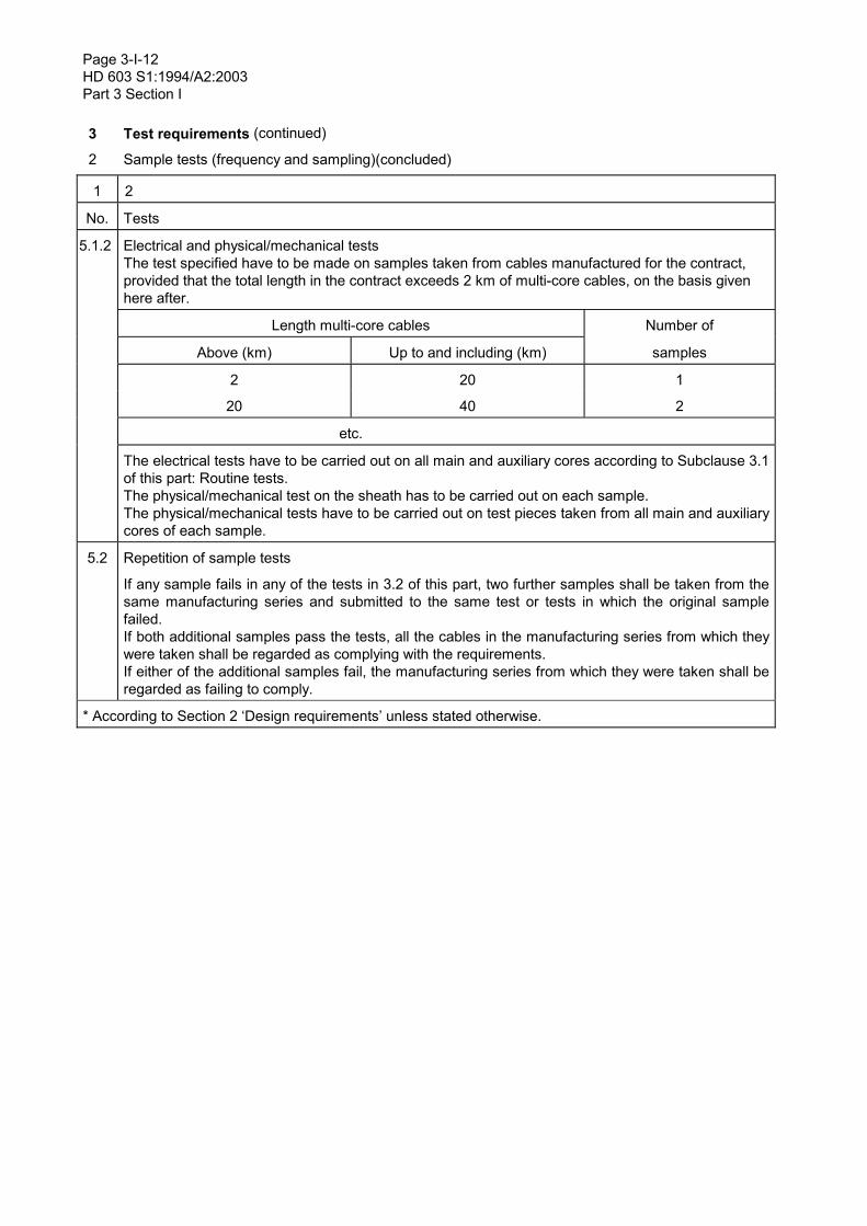
Page 3-I-12 HD 603 S1:1994/A2:2003 Part 3 Section I
3 Test requirements (continued) 2 Sample tests (frequency and sampling)(concluded)
1 2
No. Tests
5.1.2 Electrical and physical/mechanical tests The test specified have to be made on samples taken from cables manufactured for the contract, provided that the total length in the contract exceeds 2 km of multi-core cables, on the basis given here after.
Length multi-core cables Number of
Above (km) Up to and including (km) samples
2 20 1
20 40 2
etc.
The electrical tests have to be carried out on all main and auxiliary cores according to Subclause 3.1 of this part: Routine tests. The physical/mechanical test on the sheath has to be carried out on each sample. The physical/mechanical tests have to be carried out on test pieces taken from all main and auxiliary cores of each sample.
5.2 Repetition of sample tests
If any sample fails in any of the tests in 3.2 of this part, two further samples shall be taken from the same manufacturing series and submitted to the same test or tests in which the original sample failed. If both additional samples pass the tests, all the cables in the manufacturing series from which they were taken shall be regarded as complying with the requirements. If either of the additional samples fail, the manufacturing series from which they were taken shall be regarded as failing to comply.
* According to Section 2 Design requirements unless stated otherwise.

Page 3-I-13 HD 603 S1:1994/A2:2003
Part 3 Section I
3 Type tests (electrical)
1 2 3 4
No. Tests Requirements * Test methods
1 Conductor resistance Ref. no. 1.5 HD 605 Subclause 3.1.1
2 Resistance of concentric conductor
Ref. no. 6.3 HD 605 Subclause 3.1.1
3 High voltage test on complete cable ** - Test voltage (a.c.) - Duration of test - Test results
4 kV 5 min No breakdown
HD 605, Subclause 3.2.1 Four core cable without auxiliary cores: a) red and blue yellow, yellow/blue and earth b) yellow and yellow/blue red, blue and earth c) two adjacent cores remaining cores and earth
Four core cable with auxiliary cores: a) red and blue yellow, yellow/blue, all auxiliary cores and earth b) yellow and yellow/blue red, blue, all auxiliary cores and earth c) two adjacent cores and all auxiliary cores remaining cores and earth
4 High voltage test on all cores in water - Length of sample - Temperature of water - Duration of water immersion Test voltage (a.c.) - Main cores - Auxiliary cores - Duration of voltage test - Test result
10 m 20 ± 5 °C ≥ 16 h and ≤ 24 h 2,5 kV 1,5 kV 15 min No breakdown
HD 605 Subclause 3.2.2.2
5 Insulation resistance at 20 and 70° Test at 20 °C length of sample duration of water immersion water temperature Test at 70 °C length of sample duration of water immersion water temperature Results to be obtained at 20 °C and 70 °C
10 m ≥ 1 h (20 + 2) °C 10 m ≥ 2 h (70 + 2) °C Appendix, Table 4
HD 605 Subclause 3.3.1
* According to Section 2 Design requirements unless stated otherwise. ** Concentric conductor or armour, if present, shall be connected to earth.

Page 3-I-14 HD 603 S1:1994/A2:2003 Part 3 Section I
4 Type tests (non-electrical)
1 2 3 4
No. Tests Requirements * Test methods
1 Constructional characteristics See Section 2 and HD 603-1, Clause 5
Visual inspection
1.1 General construction of cable
1.2 Core identification Ref. no. 2.3
1.3 Marking Ref. no. 8 and HD 603-1, Clause 3
2 Aluminium conductors
2.1 - Condition of surface Ref. no. 1.2.1 Visual inspection
2.2 - Dimensions Ref. no. 1.7
2.3 - Tensile properties Ref. no. 1.3 HD 605, Subclause 2.3.1.2
3 Insulation
3.1 Insulation of main cores
3.1.1 - Thickness Ref. no. 2.2.1 EN 60811-1-1, Subclause 8.1 HD 605, Subclause 2.1.1
3.1.2 - Application to conductor HD 603-1 Subclause 5.2.2
Inspection and manual test
3.1.3 - Tensile properties before ageing
HD 603-1 Table 1 - DIV8
EN 60811-1-1, Subclause 9.1
3.1.4 - Tensile properties after ageing
HD 603-1 Table 1 - DIV8
EN 60811-1-1, Subclause 9.1 and EN 60811-1-2, Subclause 8.1.3.1
3.1.5 - Mechanical properties after ageing of complete cable
HD 603-1 Table 1 - DIV8
EN 60811-1-2, Subclause 8.1.4 and EN 60811-1-1, Subclause 9.1
3.1.6 - Loss of mass HD 603-1 Table 1 - DIV8
EN 60811-3-2, Subclause 8.1
3.1.7 - Pressure test at 80 °C HD 603-1 Table 1 - DIV8
EN 60811-3-1, Subclause 8.1
3.1.8 - Cold bending test at 15 °C (for diameter ≤ 12,5 mm)
HD 603-1 Table 1 - DIV8
EN 60811-1-4, Subclause 8.1
3.1.9 - Cold elongation test at 15 °C (for diameter > 12,5 mm)
HD 603-1 Table 1 - DIV8
EN 60811-1-4, Subclause 8.3
3.1.10 - Heat shock test at 150 °C HD 603-1 Table 1 - DIV8
EN 60811-3-1, Subclause 9.1
3.1.11 Water absorption HD 603-1 Table 1 - DIV8
EN 60811-1-3, Subclause 9.1
* According to Section 2 Design requirements" unless stated otherwise.

Page 3-I-15 HD 603 S1:1994/A2:2003
Part 3 Section I
3 Test requirements (continued) 4 Type tests (non-electrical, continued)
1 2 3 4
No. Tests Requirements * Test methods
3.2 Insulation of auxiliary cores
3.2.1 - Thickness Ref. no. 2.2.2 EN 60811-1-1, Subclause 8.1 HD 605, Subclause 2.1.1
3.2.2 - Tensile properties before ageing
HD 603-1 Table 1 - DIV8
EN 60811-1-1, Subclause 9.1
4 Inner covering
4.1 - Thickness Ref. no. 4.1 EN 60811-1-1, Subclause 8.2 HD 605, Subclause 2.1.2
5 Inner and outer sheath Ref. N° 5.5 to 5.9 not applicable to innersheath
5.1 - Thickness Ref. no. 5.2 Ref. no. 7.2
EN 60811-1-1, Subclause 8.2 HD 605, Subclause 2.1.2
5.2 - Tensile properties before ageing
HD 603-1 Table 4A - DMV14
EN 60811-1-1, Subclause 9.2-
5.3 - Tensile properties after ageing
HD 603-1 Table 4A - DMV14
EN 60811-1-1, Subclause 9.2 and EN 60811-1-2, Subclause 8.1
5.4 - Mechanical properties after ageing of complete cable
HD 603-1 Table 4A - DMV14
EN 60811-1-2, Subclause 8.1.4 and EN 60811-1-1, Subclause 9.2
5.5 - Loss of mass HD 603-1 Table 4A - DMV14
EN 60811-3-2, Subclause 8.2
5.6 - Pressure test at 80 °C HD 603-1 Table 4A - DMV14
EN 60811-3-1, Subclause 8.2
5.7 - Cold elongation test at 15 °C HD 603-1 Table 4A - DMV14
EN 60811-1-4, Subclause 8.4
5.8 - Cold impact test at 15 °C (for cable type 3I-3 only)
HD 603-1 Table 4A - DMV14
EN 60811-1-4, Subclause 8.5
5.9 - Heat shock test at 150 °C HD 603-1 Table 4A DMV14
EN 60811-3-1, Subclause 9.2
6 Bending test on complete cable at 0 °C followed by voltage test of 7,5 kV a.c. for 10 min
No breakdown and no visible damage
HD 605 Subclause 2.4.1.1 but at 0 ± 2 °C, 3 complete turns and cylinder diameter 12 x cable diameter
7 Flame retardance test on complete cable
EN 50265-1 and EN 50265-2-1
EN 50265-1 and EN 50265-2-1
* According to Section 2 Design requirements unless stated otherwise.

Page 3-I-16 HD 603 S1:1994/A2:2003 Part 3 Section I
4 Appendix (tables)
Main cable with four shaped solid aluminium conductors, PVC insulated, PVC sheathed, with concentric conductor, with or without auxiliary cores.
Code designation: V-VMvKsas 0,6/1 kV for cables without auxiliary cores V-VMvKhsas 0,6/1 kV for cables with auxiliary cores
Table 1 - General data for cables with concentric conductors (type 3I-1)
Number of cores and nominal cross-sectional area
Width of shaped
conductors
Protective earth concentric conductors
Thickness of insulation
Thickness of
innersheath
Thickness of
oversheath
Overall diameter
Main cores
Auxiliary cores 1)
Cross sectional
area
Resistance
Main cores
Auxiliary
cores
mm²
mm²
minimum
mm
nominal
mm²
maximum
Ω/km
specified values
mm
specified values
mm
specified values
mm
specified values
mm
nominal
mm
4 x 50 - 8,6 25 0,727 1,4 - 1,0 2,0 35
4 x 50 4 x 2,5 8,6 25 0,727 1,4 0,4 1,0 2,0 35
4 x 50 2) 4 x 6 - 25 0,727 1,4 0,4 1,0 2,2 37
4 x 95 - 11,9 35 0,524 1,6 - 1,2 2,3 47
4 x 95 4 x 2,5 11,9 35 0,524 1,6 0,4 1,2 2,3 47
4 x 95 4 x 6 11,9 35 0,524 1,6 0,4 1,2 2,3 47
4 x 150 - 15,7 50 0,387 1,8 - 1,4 2,6 55
4 x 150 4 x 2,5 15,7 50 0,387 1,8 0,4 1,4 2,6 55
4 x 150 4 x 6 15,7 50 0,387 1,8 0,4 1,4 2,6 55
4 x 240 - 21,2 70 0,268 2,2 - 1,6 3,0 65
4 x 240 4 x 2,5 21,2 70 0,268 2,2 0,4 1,6 3,0 65
4 x 240 4 x 6 21,2 70 0,268 2,2 0,4 1,6 3,0 65 1) If requested, the four auxiliary cores may be divided in two cores having the smaller and two having the marger cross-sectional area; the cables may be also provided with two auxiliary cores. 2) Circular conductors. Remark: The specified values for the thickness on insulation for the main cores are in accordance with the values given in HD 603-1, Table 5.

Page 3-I-17 HD 603 S1:1994/A2:2003
Part 3 Section I
4 Appendix (tables) (continued)
Main cable with four shaped solid aluminium conductors, PVC insulated, PVC sheathed, with or without auxiliary cores
Code designation: VMvK 0,6/1 kV for cables without auxiliary cores VMvKh 0,6/1 kV for cables with auxiliary cores
Table 2 General data for cables without concentric conductors (type 3I-2)
Number of cores and nominal
cross-sectional area
Width of shaped
conductors
Thickness of insulation Thickness of inner-covering
Thickness of sheath
Overall diameter
Main cores
Auxiliary cores 1)
Main cores
Auxiliary
cores
mm²
mm²
minimum
mm
specified values
mm
specified values
mm
specified values
mm
specified values
mm
nominal
mm
4 x 50 - 8,6 1,4 - 3,0 3,0 36
4 x 50 4 x 2,5 8,6 1,4 0,4 3,0 3,0 36
4 x 50 2) 4 x 6 - 1,4 0,4 3,0 3,0 38
4 x 95 - 11,9 1,6 - 3,0 3,0 43
4 x 95 4 x 2,5 11,9 1,6 0,4 3,0 3,0 43
4X95 4 x 6 11,9 1,6 0,4 3,0 3,0 43
4 x 150 - 15,7 1,8 - 3,0 3,0 49
4 x 150 4 x 2,5 15,7 1,8 0,4 3,0 3,0 49
4 x 150 4 x 6 15,7 1,8 0,4 3,0 3,0 49
4 x 240 - 21,2 2,2 - 3,0 3,0 59
4 x 240 4 x 2,5 21,2 2,2 0,4 3,0 3,0 59
4 x 240 4 x 6 21,2 2,2 0,4 3,0 3,0 59
1) If requested, the four auxiliary cores may be divided in two cores having the smaller and two having the marger cross-sectional area; the cables may be also provided with two auxiliary cores. 2) Circular conductors. Remark: The specified values for the thickness on insulation for the main cores are in accordance with the values given in HD 603-1, Table 5.

Page 3-I-18 HD 603 S1:1994/A2:2003 Part 3 Section I
4 Appendix (tables) (continued)
Service cable with four conductors, PVC insulated, PVC sheathed, with or without auxiliary cores
Code designation: VMvK 0,6/1 kV for cables without auxiliary cores VMvKh 0,6/1 kV for cables with auxiliary cores
Table 3 - General data for cables without concentric conductors (type 3I-3)
Number of cores and nominal cross sectional area
Main conductor HD 383 class
Thickness of insulation
Thickness of inner-covering
Thickness of sheath
Overall diameter
Main cores
Auxiliary cores 1)
Copper
Aluminium
Main cores
Auxiliary
cores
mm²
mm²
specified values
mm
specified values
mm
specified values
mm
specified values
mm
nominal
mm
4 x 6 - 1 1,0 - 3,0 3,0 26
4 x 6 4 x 1,5 1 1,0 0,4 3,0 3,0 26
4 x 6 4 x 2,5 1 1,0 0,4 3,0 3,0 26
4 x 10 - 1 1,0 - 3,0 3,0 28
4 x 10 4 x 2,5 1 1,0 0,4 3,0 3,0 28
4 x 16 - 2 1 1,0 - 3,0 3,0 29
4 x 16 4 x 1,5 2 1 1,0 0,4 3,0 3,0 29
4 x 25 - 2 1,2 - 3,0 3,0 35
4 x 25 4 x 2,5 2 1,2 0,4 3,0 3,0 35
1) If requested, the four auxiliary cores may be divided in two cores having the smaller and two having the larger cross-sectional area; the cables may be also provided with two auxiliary cores. Remark: The specified values for the thickness on insulation for the main cores are in accordance with the values given in HD 603-1, Table 5.

Page 3-I-19 HD 603 S1:1994/A2:2003
Part 3 Section I
4 Appendix (tables, concluded)
Table 4 Insulation resistance of PVC insulated cores in water
Nominal cross-sectional area mm²
Minimum insulation resistances MΩ.km
20 °C 70 °C
1,5 auxiliary cores 5,1 5,1 x 10-³
2,5 auxiliary cores 4,1 4,1 x 10-³
6 auxiliary cores 2,7 2,7 x 10-³
6 main cores 8,0 8,0 x 10-³
10 main cores 7,1 7,1 x 10-³
16 main cores 5,8 5,8 x 10-³
25 main cores 5,6 5,6 x 10-³
50 main cores 4,8 4,8 x 10-³
95 main cores 4,1 4,1 x 10-³
150 main cores 3,7 3,7 x 10-³
240 main cores 3,6 3,6 x 10-³
The minimum insulation resistances are based on a volume resistivity of:
1013 Ω.cm at 20 °C 1010 Ω.cm at 70 °C
4 Appendix Guide to use 1 Scope
This "Guide to use" is applicable to cables according to Section 3-I of HD 603.
2 Object
The object of this "Guide to use" is to provide recommendations for the storage, transport and handling of the cables.
3 Recommendations for storage, transport and handling
3.1 Delivery
When delivered on a drum the core diameter of the drum shall not be less than:
- 15 times the outer diameter of the cable.
The distance between the outer cable layer and the head of the drum flange shall be sufficiently high to avoid damages to the cable.
Short cable lengths may be coiled to rings and transported and stored horizontally. The bending radii shall not be less than the above mentioned values.

Page 3-I-20 HD 603 S1:1994/A2:2003 Part 3 Section I
4 Appendix Guide to use (continued) 3.2 Cable end sealing
The cable ends shall be sealed waterproof during transport, storage and laying.
3.3 Transport
For the transport of filled up cable reels only suitable carriers shall be used.
Cables stored at temperatures which fall below those recommended for installation shall not be subject to any mechanical stress including shocks, impact, bending and torsion.
It shall be prevented that drum flanges come in touch with the cable of another drum.
For loading and unloading of cable drums suitable lifting and hoisting equipment shall be used; never drop a drum on the ground or on a buffer.
See also relevant figures.
Filled up cable drums shall be rolled only on short distances over plain solid ground in the direction indicated.
The cable end shall be tightened.
3.4 Lowest temperature for cable laying and installation
Insulation and sheath of PVC is liable to cracking at low temperatures in case of strokes against the cable or excessive bending. Care should therefore be taken during transport, laying and installation.
Lowest temperature of cable during installation is 2 °C under normal conditions of care.
This temperature is valid for the cable itself and not for the environment. If possible, the temperature of the cable shall be raised to at least + 10 °C before laying, e.g. in a heated building, to facilitate handling and to reduce the risk of damages.
3.5 Pulling loads
It is assumed that the cable route is well designed for the laying procedure with well established curves and a sufficient number of cable rollers. Special attention shall be paid to the required minimum bending radii (see Subclause 3.6 of this appendix). The pulling forces shall be permanently supervised during the pull-in procedure.
The pulling force shall be evenly divided over the main conductors.
The maximum pulling force (P) shall be calculated as follows:
P = S σ where P is in N σ is maximum tensile stress in conductor, viz. 50 N / mm² for copper conductor 20 N / mm² for aluminium conductors (solid)
S is total cross-sectional area in mm² of the main conductors (ignoring screens, concentric conductors and auxiliary conductors).
In case of using a cable stocking, the total pulling force shall not exceed 3 D² in N, where D is cable diameter in mm however has to have a smaller value for the pulling force as determined by the conductors.
3.6 Bending radius
During installation the internal bending radius of the cable shall not be smaller than 12 D, where D is the overall diameter of the cable. This value may be reduced to 10 D in case of a careful, one single time bending of the cable end.
Bending nearby the temperature limits given in Subclause 3.4 of this appendix should be carried out extra carefully.
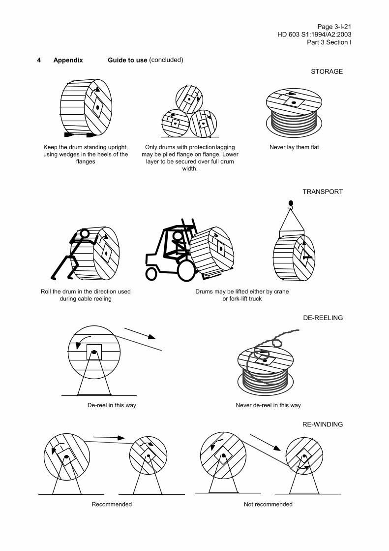
Page 3-I-21 HD 603 S1:1994/A2:2003
Part 3 Section I
4 Appendix Guide to use (concluded) STORAGE
Keep the drum standing upright, using wedges in the heels of the
flanges
Only drums with protection lagging may be piled flange on flange. Lower
layer to be secured over full drum width.
Never lay them flat
TRANSPORT
Roll the drum in the direction used
during cable reeling Drums may be lifted either by crane
or fork-lift truck DE-REELING
De-reel in this way Never de-reel in this way
RE-WINDING
Recommended Not recommended
Page 3-I-22 HD 603 S1:1994/A2:2003 Part 3 Section I
BLANK PAGE

Page 3-L-0 HD 603 S1:1994/A2:2003
Part 3 Section L
SECTION 3-L - CABLES WITH CONCENTRIC CONDUCTOR (TYPE 3L)
Replace Section 3-L
by the following A2 referred new Section 3-L:


Page 3-L-1 HD 603 S1:1994/A2:2003
Part 3 Section L
SECTION 3-L - CABLES WITH CONCENTRIC CONDUCTOR (TYPE 3L)

Page 3-L-2 HD 603 S1:1994/A2:2003 Part 3 Section L
CONTENTS
1 General-------------------------------------------------------------------------------------------------------------------------- 4
2 Design requirements --------------------------------------------------------------------------------------------------------- 5
1 Conductor ------------------------------------------------------------------------------------------------------------- 5 1.1 Material 1.2 Dimensions of circular conductors 1.3 Dimensions of sector-shaped conductors 1.4 Conductor resistance 1.5 Permissible conductor types 1.6 Preferred number of conductors and conductor cross sections
2 Insulation -------------------------------------------------------------------------------------------------------------- 5 2.1 Material 2.2 Insulation thickness 2.3 Form of insulation on sector shaped conductors 2.4 Core identification
3 Assembly of cores--------------------------------------------------------------------------------------------------- 5 3.1 Assembly
4 Inner covering -------------------------------------------------------------------------------------------------------- 5 4.1 Design 4.2 Thickness
5 Concentric conductor----------------------------------------------------------------------------------------------- 6 5.1 Design 5.2 Inner layer 5.3 Binder wire and binder tape 5.4 Nominal cross section 5.5 Resistance
6 Oversheath ----------------------------------------------------------------------------------------------------------- 7 6.1 Material 6.2 Colour 6.3 Thickness
7 Outer diameter ------------------------------------------------------------------------------------------------------- 7
8 Marking ---------------------------------------------------------------------------------------------------------------- 7 8.1 Indication of origin 8.2 Additional marking 8.3 Continuity of marks 8.4 Durability 8.5 Legibility 8.6 Meter marking
9 Code designation---------------------------------------------------------------------------------------------------- 7
3 Test requirements ------------------------------------------------------------------------------------------------------------ 8 1 Routine tests --------------------------------------------------------------------------------------------------------- 8 2 Sample tests---------------------------------------------------------------------------------------------------------- 8 3 Type tests, electrical------------------------------------------------------------------------------------------------ 8 4 Type tests, non-electrical ------------------------------------------------------------------------------------------ 9
4 Appendix 11
Appendix 1 (tables)------------------------------------------------------------------------------------------------------11 Appendix 2 (Lead content determination test) --------------------------------------------------------------------15
5 Guide to use ------------------------------------------------------------------------------------------------------------------17
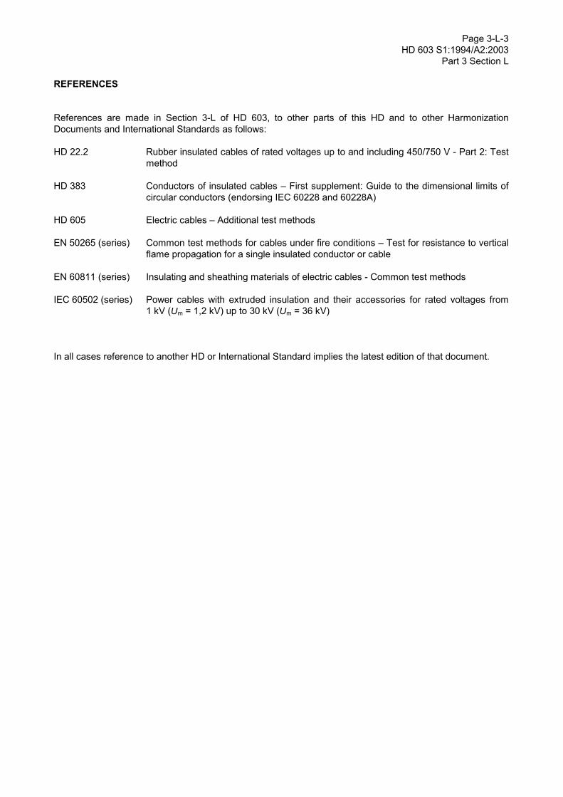
Page 3-L-3 HD 603 S1:1994/A2:2003
Part 3 Section L
REFERENCES
References are made in Section 3-L of HD 603, to other parts of this HD and to other Harmonization Documents and International Standards as follows:
HD 22.2 Rubber insulated cables of rated voltages up to and including 450/750 V - Part 2: Test method
HD 383 Conductors of insulated cables First supplement: Guide to the dimensional limits of circular conductors (endorsing IEC 60228 and 60228A)
HD 605 Electric cables Additional test methods
EN 50265 (series) Common test methods for cables under fire conditions Test for resistance to vertical flame propagation for a single insulated conductor or cable
EN 60811 (series) Insulating and sheathing materials of electric cables - Common test methods
IEC 60502 (series) Power cables with extruded insulation and their accessories for rated voltages from 1 kV (Um = 1,2 kV) up to 30 kV (Um = 36 kV)
In all cases reference to another HD or International Standard implies the latest edition of that document.

Page 3-L-4 HD 603 S1:1994/A2:2003 Part 3 Section L
1 General
This standard specifies the construction, dimensions and test requirements of power cables with PVC insulation and with concentric conductor for rated voltage (U) of 1 kV for fixed installations. All components shall be lead free
(a) Insulating materials
The insulation covered by this standard shall consist of polyvinyl chloride and correspond to Table 1of HD 603-1, type DIV 11.
(b) Rated voltage
0,6/1kV
Definitions: see HD 603-1, Subclause 2.3
(c) Highest rated temperatures for the different types of insulating compound
Normal operation 70 °C
(d) Sheathing material
Shall be suitable for the maximum rated conductor temperature. It shall consist of PVC and correspond to Table 4A of HD 603-1, type DMV 19.

Page 3-L-5 HD 603 S1:1994/A2:2003
Part 3 Section L
2 Design requirements
Cable component Requirements
HD Additional
1 Conductor HD 603-1 Subclause 5.1
1.1 Material HD 603-1 Subclause 5.1.1
Aluminium conductors shall be annealed
1.2 Dimensions of circular conductors
HD 383
1.3 Dimensions of sector-shaped conductors
1.4 Conductor resistance HD 383
1.5 Permissible conductor types Appendix, Table 1
1.6 Preferred number of conductors and conductor cross sections
Appendix, Tables 2 and 3
2 Insulation HD 603-1 Subclause 5.2
2.1 Material HD 603-1, Table 1, compound DIV 11, lead free
2.2 Insulation thickness a) nominal value b) mean value c) minimum value
HD 603-1 Table 5
≥ nominal value ≥ nominal value - (0,1 + 10 % of nominal value)
NOTE The thickness of any separator on the conductor or over the insulation shall not be included in the thickness of the insulation.
2.3 Form of insulation on sector-shaped conductors
To prevent moisture penetration in joints, the insulation on the plain faces of a sector-shaped conductor may not curve in.
2.4 Core identification Appendix, Table 7
3 Assembly of cores
3.1 Assembly Cores of multi-core cables shall be cabled, helically or oscillating with an average length of lay not more than 50 times the diameter over the cabled cores.
4 Inner covering HD 603-1 Subclause 5.5
The material used for inner coverings and fillers shall be suitable for the operating temperature of the cable and compatible with and not sticking to adjacent materials

Page 3-L-6 HD 603 S1:1994/A2:2003 Part 3 Section L
2 Design requirements (continued)
No. Cable component Requirements
HD Additional
4.1 Design for a) single-core cables b) multi-core cables with round conductors c) multi-core cables with sector shaped conductors
No inner covering required An extruded covering shall be applied over the cabled cores and substantially fill the interstices between the cores As an alternative a lapped inner covering is permitted when the interstices are substantially filled by seperate filler strings A lapped inner covering shall be applied over the cabled cores. As an alternative an extruded inner covering is permitted. In the latter case a helically applied tape, lapped or in open helix, may be applied over the cable cores.
4.2 Thickness HD 603-1 Subclause 5.5.3
Appendix, Table 4
5 Concentric conductor
5.1 Design In single-core cables the concentric conductor may be applied directly over the insulation. In multi-core cables, the concentric conductor shall be applied over the inner covering. The concentric conductor shall consist of an inner layer of annealed, round or flat copper wires applied concentrically on the cable cores, and an outer layer with one or more spiral binder wires or tapes of copper in contact with the wires in the inner layer.
5.2 Inner layer The inner layer shall have an average length of lay not more than 50 times the diameter over the cabled cores. The average gap between individual wires in the inner layer may not exceed 4 mm
5.3 Binder wire and binder tape A binder wire in the outer layer shall have at least the same cross section as a wire in the inner layer. A binder tape shall have a thickness of at least 0,1 mm and a width of at least 10 mm. The lay of length shall be: - for binder tape not more than 20 times - for binder wire not more than 50 times the diameter over the cabled cores.
5.4 Nominal cross section Appendix, Table 5
5.5 Resistance The electrical resistance shall be as specified in HD 383 for a Class 2 copper conductor of the same cross section. For cross sections not specified in HD 383 the resistance values are given in Appendix, Table 6

Page 3-L-7 HD 603 S1:1994/A2:2003
Part 3 Section L
2 Design requirements (concluded)
No. Cable component Requirements
HD Additional
6 Oversheath HD 603-1 Subclause 5.8
6.1 Material HD 603-1, Table 4A compound DMV 19, lead free
6.2 Colour Black
6.3 Thickness a) nominal thickness b) mean value c) minimum thickness
Appendix, Tables 2 and 3 For cables not specified in Tables 2 or 3, the thickness shall be calculated in accordance with the formula in IEC 60502, Subclause 12.3 a. ≥ nominal value ≥ nominal value - (0,1 mm + 15 % of nominal value)
7 Outer diameter Appendix, Tables 2 and 3
8 Marking HD 603-1 Subclause 3
8.1 Indication of origin on the oversheath
Manufacturers name or trademark which shall be legally protected and from which the manufacturer can be identified. A registered identification thread in the cable is permitted.
8.2 Additional marking Type designation, number and size of conductors, size of concentric conductor, rated voltage and year of manufacture (2 last digits)
8.3 Continuity of marks Distance between the end of one mark and the beginning of the next ≤ 1 m
8.4 Durability HD 603-1 Subclause 3.3
Marking on the oversheath must be resistant to conditions in the ground.
8.5 Legibility HD 603-1 Subclause 3.4
8.6 Meter marking A meter marking with reasonable accuracy shall be applied on the oversheath and in such way that it does not interfere with the markings above
9 Code designation (provisional)
Cables with: - solid copper conductor (EKKJ)- stranded copper conductor (FKKJ)- stranded aluminium conductor (AKKJ)
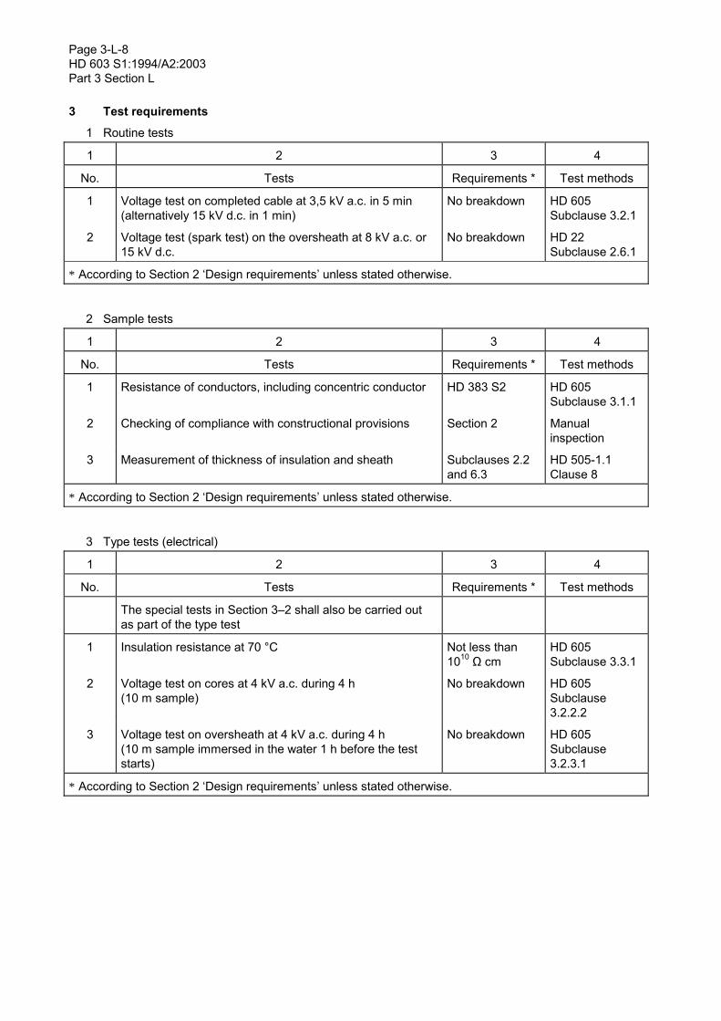
Page 3-L-8 HD 603 S1:1994/A2:2003 Part 3 Section L
3 Test requirements 1 Routine tests
1 2 3 4
No. Tests Requirements * Test methods
1 Voltage test on completed cable at 3,5 kV a.c. in 5 min (alternatively 15 kV d.c. in 1 min)
No breakdown HD 605 Subclause 3.2.1
2 Voltage test (spark test) on the oversheath at 8 kV a.c. or 15 kV d.c.
No breakdown HD 22 Subclause 2.6.1
* According to Section 2 Design requirements unless stated otherwise.
2 Sample tests
1 2 3 4
No. Tests Requirements * Test methods
1 Resistance of conductors, including concentric conductor HD 383 S2 HD 605 Subclause 3.1.1
2 Checking of compliance with constructional provisions Section 2 Manual inspection
3 Measurement of thickness of insulation and sheath Subclauses 2.2 and 6.3
HD 505-1.1 Clause 8
* According to Section 2 Design requirements unless stated otherwise.
3 Type tests (electrical)
1 2 3 4
No. Tests Requirements * Test methods
The special tests in Section 32 shall also be carried out as part of the type test
1 Insulation resistance at 70 °C Not less than 1010 Ω cm
HD 605 Subclause 3.3.1
2 Voltage test on cores at 4 kV a.c. during 4 h (10 m sample)
No breakdown HD 605 Subclause 3.2.2.2
3 Voltage test on oversheath at 4 kV a.c. during 4 h (10 m sample immersed in the water 1 h before the test starts)
No breakdown HD 605 Subclause 3.2.3.1
* According to Section 2 Design requirements unless stated otherwise.

Page 3-L-9 HD 603 S1:1994/A2:2003
Part 3 Section L
3 Test requirements (continued) 4 Type tests (non-electrical)
1 2 3 4
No. Tests Requirements * Test methods
The special tests in Section 3 2 shall also be carried out as part of the type test
1
1.1
Tests on insulation Mechanical properties before and after ageing
HD 603-1 Table 1 DIV 11
EN 60811-1-1 Subclause 9.1 EN 60811-1-2 Subclause 8.1
1.2 Loss of mass test EN 60811-3-2 Subclause 8.1
1.3 Elongation test at low temperature (cores with a diameter over 12,5 mm)
HD 603-1 Table 1 DIV 11
EN 60811-1-4 Subclause 8.3
2 2.1
Test on cores Pressure test at high temperature
HD 603-1 Table 1 DIV 11
EN 60811-3-1 Subclause 8.1
2.2 Heat shock test HD 603-1 Table 1 DIV 11
EN 60811-3-1 Subclause 9.1
2.3 Bending test at low temperature on cores with a diameter up to 12,5 mm
HD 603-1 Table 1 DIV 11
EN 60811-1-4 Subclause 8.1
2.4 Water absorption HD 603-1 Table 1 DIV 11
EN 60811-1-3 Subclause 9.1
3 3.1
Tests on fillers and tapes Lead content detrermination test
HD 603-3 Section L Appendix 2
HD 603-3 Section L Appendix 2
4 4.1
Tests on sheath Mechanical properties before and after ageing
HD 603-1 Table 4A DMV 19
EN 60811-1-1 Subclause 9.2 EN 60811-1-2 Subclause 8.1
4.2 Loss of mass test HD 603-1 Table 4A DMV 19
EN 60811-3-2 Subclause 8.2
4.3 Pressure test at high temperature HD 603-1 Table 4A DMV 19
EN 60811-3-1 Subclause 8.2
4.4 Heat shock test HD 603-1 Table 4A DMV 19
EN 60811-3-1 Subclause 9.2
4.5 Elongation test at low temperature HD 603-1 Table 4A DMV 19
EN 60811-1-4 Subclause 8.4
4.6 Lead content determination test HD 603-3 Section L Appendix 2
HD 603-3 Section L Appendix 2
* According to Section 2 Design requirements unless stated otherwise.
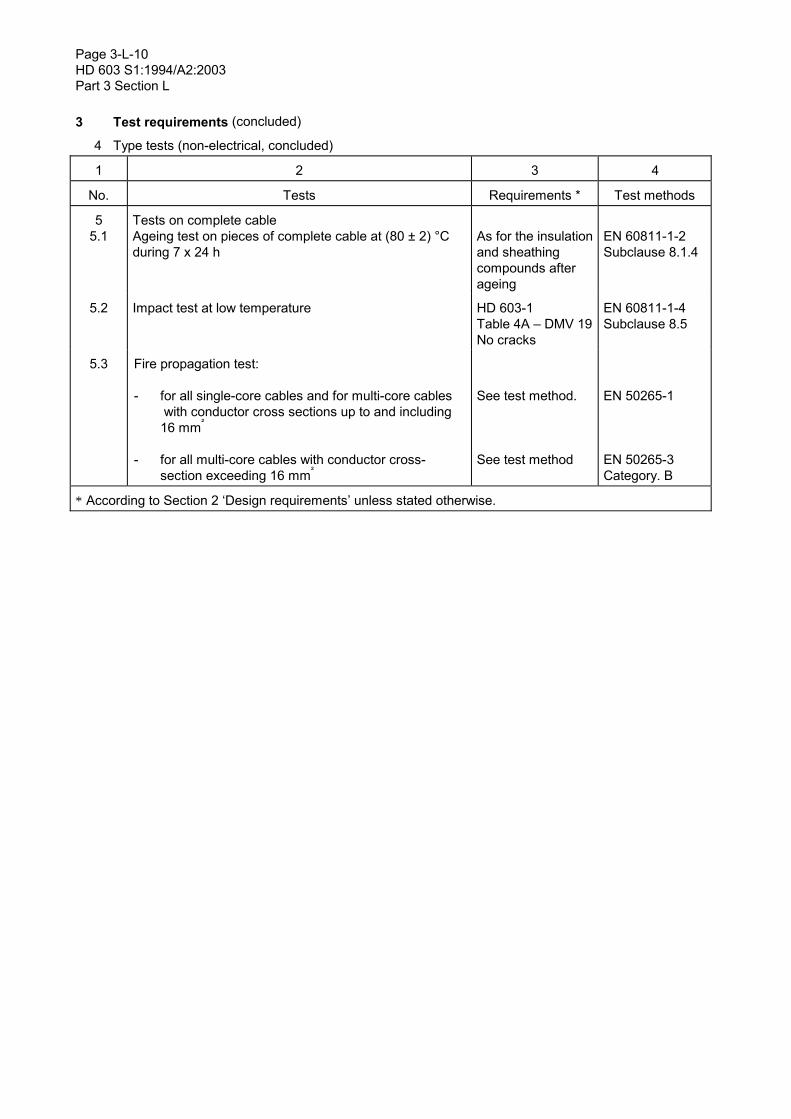
Page 3-L-10 HD 603 S1:1994/A2:2003 Part 3 Section L
3 Test requirements (concluded) 4 Type tests (non-electrical, concluded)
1 2 3 4
No. Tests Requirements * Test methods
5 5.1
Tests on complete cable Ageing test on pieces of complete cable at (80 ± 2) °C during 7 x 24 h
As for the insulation and sheathing compounds after ageing
EN 60811-1-2 Subclause 8.1.4
5.2 Impact test at low temperature HD 603-1 Table 4A DMV 19 No cracks
EN 60811-1-4 Subclause 8.5
5.3 Fire propagation test: - for all single-core cables and for multi-core cables with conductor cross sections up to and including 16 mm² - for all multi-core cables with conductor cross- section exceeding 16 mm²
See test method. See test method
EN 50265-1 EN 50265-3 Category. B
* According to Section 2 Design requirements unless stated otherwise.

Page 3-L-11 HD 603 S1:1994/A2:2003
Part 3 Section L
4 Appendix 1
Table 1 - Range of conductor types, sizes and shapes and number of conductors covered by the specification
Conductor material Number of conductors Cross section mm²
Shape
1 2,5 - 1 000 Round
2 2,5 - 16 Round
3 2,5 - 16 Round
Copper 25 - 400 Sector 1)
4 2,5 - 16 Round
25 - 400 Sector 1)
1 16 - 1 000 Round
2 16 Round
3 16 Round
Aluminium 25 - 400 Sector 1)
4 16 Round
25 - 400 Sector 1) 1) 25 mm² and 35 mm² conductors may be round as alternative.
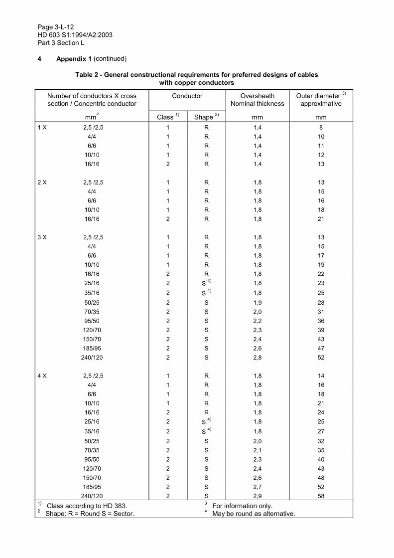
Page 3-L-12 HD 603 S1:1994/A2:2003 Part 3 Section L
4 Appendix 1 (continued)
Table 2 - General constructional requirements for preferred designs of cables with copper conductors
Number of conductors X cross section / Concentric conductor
Conductor
Oversheath Nominal thickness
Outer diameter 3) approximative
mm² Class 1) Shape 2) mm mm 1 X 2,5 /2,5 1 R 1,4 8
4/4 1 R 1,4 10 6/6 1 R 1,4 11
10/10 1 R 1,4 12 16/16 2 R 1,4 13
2 X 2,5 /2,5 1 R 1,8 13
4/4 1 R 1,8 15 6/6 1 R 1,8 16
10/10 1 R 1,8 18 16/16 2 R 1,8 21
3 X 2,5 /2,5 1 R 1,8 13
4/4 1 R 1,8 15 6/6 1 R 1,8 17
10/10 1 R 1,8 19 16/16 2 R 1,8 22 25/16 2 S 4) 1,8 23 35/16 2 S 4) 1,8 25 50/25 2 S 1,9 28 70/35 2 S 2,0 31 95/50 2 S 2,2 36
120/70 2 S 2,3 39 150/70 2 S 2,4 43 185/95 2 S 2,6 47
240/120 2 S 2,8 52 4 X 2,5 /2,5 1 R 1,8 14
4/4 1 R 1,8 16 6/6 1 R 1,8 18
10/10 1 R 1,8 21 16/16 2 R 1,8 24 25/16 2 S 4) 1,8 25 35/16 2 S 4) 1,8 27 50/25 2 S 2,0 32 70/35 2 S 2,1 35 95/50 2 S 2,3 40
120/70 2 S 2,4 43 150/70 2 S 2,6 48 185/95 2 S 2,7 52
240/120 2 S 2,9 58 1) Class according to HD 383. 3 For information only. 2 Shape: R = Round S = Sector . 4 May be round as alternative.

Page 3-L-13 HD 603 S1:1994/A2:2003
Part 3 Section L
4 Appendix 1 (continued)
Table 3 - General constructional requirements for preferred designs of cables with sector shaped alumunium conductors
Number of conductors X cross section / concentric conductor 1)
Oversheath nominal thickness
Outer diameter 2) approximative
mm² mm mm 3 X 50/15 1,9 28
70/21 (*) 2,0 31
95/29 2,1 35
120/41 (*) 2,3 38
150/41 2,4 42
185/57 (*) 2,6 47
240/72 2,8 52
300/88 (*) 3,0 57 4 X 50/15 2,0 31
70/21 (*) 2,1 34
95/29 2,3 40
120/41 (*) 2,4 43
150/41 2,6 48
185/57 (*) 2,7 52
240/72 2,9 58
300/88 (*) 3,2 65 1) Cable with (*) should only be chosen as a second alternative. 2) For information only.
Table 4 - Thickness of extruded or lapped inner covering
Fictitious diameter over laid up cores Thickness of extruded inner covering
Above Up to and including (approximate values)
mm mm mm
- 25 1,0
25 35 1,2
35 45 1,4
45 60 1,6
60 80 1,8
80 - 2,0
The approximate thickness of lapped covering shall be 0,4 mm for fictitious diameters over laid-up cores up to and including 40 mm and 0,6 mm for larger diameters.
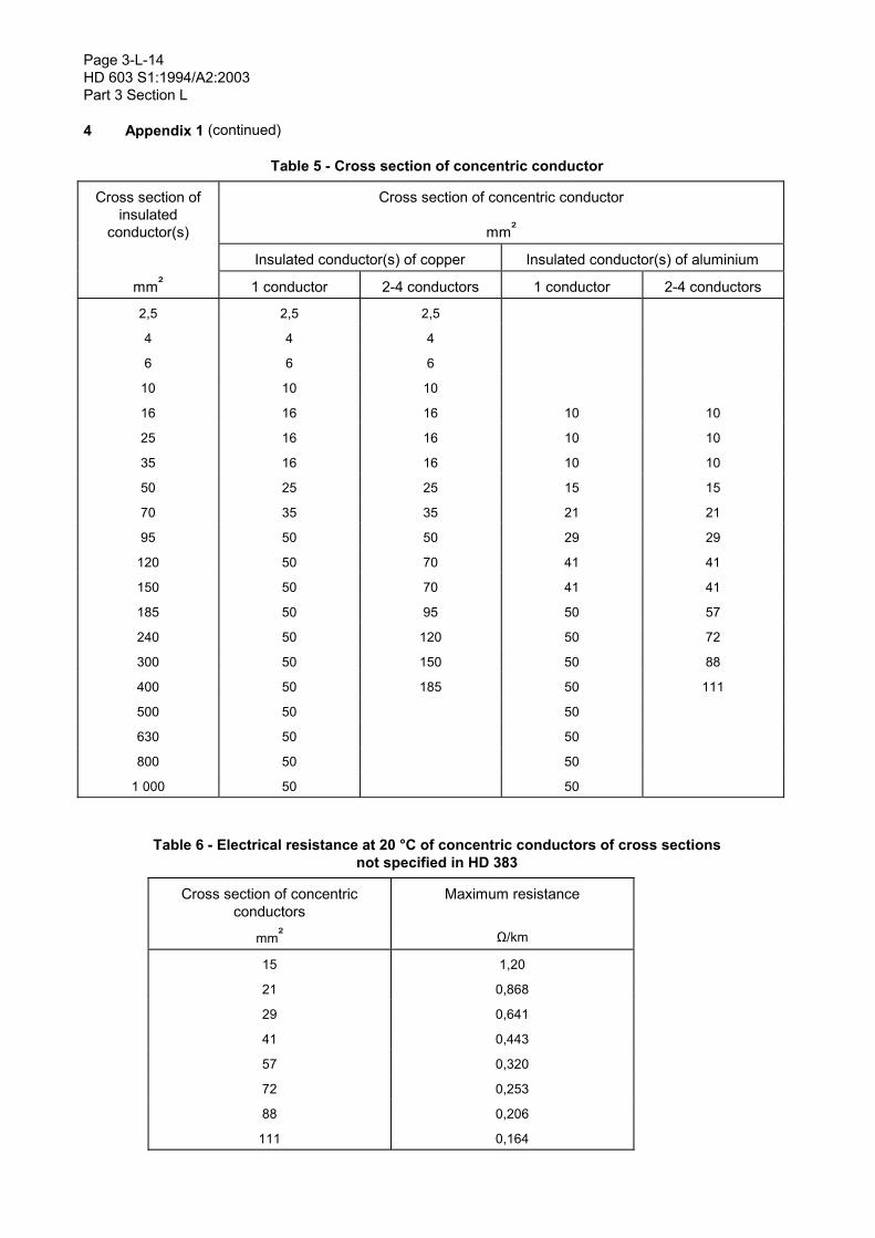
Page 3-L-14 HD 603 S1:1994/A2:2003 Part 3 Section L
4 Appendix 1 (continued)
Table 5 - Cross section of concentric conductor
Cross section of insulated
conductor(s)
Cross section of concentric conductor
mm²
Insulated conductor(s) of copper Insulated conductor(s) of aluminium
mm² 1 conductor 2-4 conductors 1 conductor 2-4 conductors
2,5 2,5 2,5
4 4 4
6 6 6
10 10 10
16 16 16 10 10
25 16 16 10 10
35 16 16 10 10
50 25 25 15 15
70 35 35 21 21
95 50 50 29 29
120 50 70 41 41
150 50 70 41 41
185 50 95 50 57
240 50 120 50 72
300 50 150 50 88
400 50 185 50 111
500 50 50
630 50 50
800 50 50
1 000 50 50
Table 6 - Electrical resistance at 20 °C of concentric conductors of cross sections not specified in HD 383
Cross section of concentric conductors
Maximum resistance
mm² Ω/km
15 1,20
21 0,868
29 0,641
41 0,443
57 0,320
72 0,253
88 0,206
111 0,164
Page 3-L-15 HD 603 S1:1994/A2:2003
Part 3 Section L
4 Appendix 1 (concluded)
Table 7 - Core identification The cores shall be identified by the following colours and numbering on the insulation:
- black cores with figure printing 1-2-3-4, depending on the number of conductors; (Requirements according to HD186 S2, Clause 5) Single-core cables need no figure.
- alternatively colour identification without figures is permitted with the following colours:
for figure:
1: black (marking with a white stripe may be used) 2: brown 3: black 4: blue.
If marking with a white stripe is used, the width of the stripe shall not be less than 0,5 mm and not more than 5 % of the circumference of the core.
4 Appendix 2 - Lead content determination test in PVC-materials
1 Measuring the lead content
Insulation, bedding and sheath shall be lead free. Below two test methods can be used to measure the lead content: simplified and extended test method. The extended test method must be chosen when the simplified test method indicates a lead content. When the extended test method is chosen the allowed maximum lead content is 400 ppm (0,04 %).
2 Simplified test method for detecting lead
General
The method is a non-quantitative test for determining the occurrence of lead in PVC, i.e. the amount can not be determined. The method shows, after approximately 10 minutes, if there is any lead stabiliser in the product. The specimen will then be discoloured darker.
The result is due to a reaction where sulphur hydrogen, H2S, reacts with lead and forms lead sulphide, which is black. Other metal sulphides, for example copper sulphide, are black as well and accordingly does the method not exclusively indicate the occurrence of lead.
As the occurrence of lead is disclosed by a dark discoloration of the specimen, the method can be difficult to verify when testing black coloured specimens.
If there are any doubts, the extended test method should be used.
(Sulphur hydrogen is a poisonous gas with unpleasant scent. The used chemicals, hydrochloric acid and sodium sulphide, are corrosive. Use protective goggles and avoid skin contact with the chemicals).
Page 3-L-16 HD 603 S1:1994/A2:2003 Part 3 Section L
4 Appendix 2 - Lead content determination test in PVC-materials (continued)
Equipment
fume cupboard
glass bowl, 200 ml, to place in the exsiccator
10 % solution of hydrochloric acid
35 % solution of sodium sulphide (35 g Na2S hydrate in 100 ml water)
graduated glass for measuring 10 ml of liquid
Procedure
The examination is made in a fume cupboard with evacuation. The specimen is cut out and put in glass bowls. To facilitate the visual judgement a gauge with the known lead content can be made, preferably in the same colour as the specimen. 10 ml solution of sodium sulphide is poured in a empty glass bowl, then is 10 ml solution of hydrochloric acid poured in the same bowl. Sulphur hydrogen is evolved at once, so put on the lid on the exsiccator immediately.
Demands
The specimens shall not show any dark discoloration after 30 minutes.
NOTE A dark discoloration occurs after 10 minutes on products with normal content of lead stabiliser. After twenty-four hours will even products with lower lead content (< 400 ppm) be discoloured dark. However, at these low levels the discoloration will be difficult to detect without help form a gauge.
3 Extended test method for detecting the lead content
General
2 x 5 grams of specimen is carefully weighed. The specimen is incinerated in an oven at 450 °C for 16 hours.
After that approximately 1 gram of the ash is dissolved in HNO3, the solution is placed in an autoclave for 5 hours in 185 °C.
The samples are cooled down, filtered and transfered to 100 ml graduated flasks. The lead content is determined by atomic absorption spectrophotometry, where the measurement is made at 217,0 nm wave length.
Demands
The lead content shall not exceed 400 ppm.

Page 3-L-17 HD 603 S1:1994/A2:2003
Part 3 Section L
5 Guide to use 1 Scope
This "Guide to use" is applicable to cables according to Section 3-L of HD 603.
2 Object
The object of this "Guide to use" is to provide recommendations for the selection, storage, transportation and installation of the cables type 3L of HD 603.
NOTE Safety regulations are not covered in this guide as they are covered by the relevant national regulations and laws.
3 Recommendations for use
3.1 Permissible applications
The cables may be installed indoors and outdoors and may be laid in the ground and in water.
3.2 Permissible voltage
The rated voltage of the cable, expressed as Uo/U, is 0,6/1 kV.
Uo is the r.m.s. value between any insulated conductor and "earth" (metal covering of the cable or the surrounding medium);
U is the r.m.s. value between any two-phase conductors of a multicore cable or of a system of single-core cables.
In an alternating current system, the nominal voltage of the system shall be not higher than the rated voltage of the cable. This condition applies both to the value Uo and to the value U.
In a direct current system, the nominal voltage of the system shall be not higher than 1,5 times the rated voltage of the cable.
NOTE The operating voltage of a system may permanently exceed the nominal voltage of such a system by 10 %. A cable can be used at 10 % higher operating voltage than its rated voltage if the latter is at least equal to the nominal voltage of the system.
3.3 Concentric conductor
The concentric conductor may be used as neutral, PE-conductor, PEN-conductor or as a screen
4 Recommendations for storage and transport
4.1 Delivery
When delivered on a drum the core diameter of the drum shall not be less than
- 16 times the outer diameter of the cable for multi-core cables,
- 20 times the outer diameter of the cable for single-core cables.
The distance between the outer cable layer and the head of the drum flange shall be sufficiently high to avoid damages to the cable.
Short cable lengths may be coiled to rings and transported and stored horizontally. The bending radii shall not be less than the values given in Subclause 5.4 below.
4.2 Cable end sealing
The cable ends shall be sealed waterproof during transport, storage and laying.

Page 3-L-18 HD 603 S1:1994/A2:2003 Part 3 Section L
5 Guide to use (continued) 4.3 Transport
For the transport of filled up cable reels only suitable carriers shall be used.
Cable drums with a total weight exceeding 2,5 tons have to be transported with the drum-axis in horizontal position. The drums have to be protected against movement. Loading and unloading shall be made by suitable devices to avoid damages of the cables and of the cable-drums.
Filled-up cable-drums shall be rolled only short distances over plain solid ground in the direction indicated. The cable ends have to be tightened.
5 Recommendations for cable laying and installation
5.1 General recommendations
The cable route, the laying method and the service conditions shall be taken into account when selecting the type of cable.
5.1.1 Cables shall be laid and operated in such a way that their properties are not endangered. In this context the following items are exemples of what shall be taken into account:
- The service conditions like cable concentrations, external heat, solar radiation, heat resistance of soil, etc
- Vibrations and movements of soil
- Protection against other outer influences like chemical solvents
- Stray currents and corrosion
- Method of laying and choice of bedding material
5.1.2 Cables shall be protected against mechanical damages that may occur after installation. For cables laid in ground local regulations for laying depth and external protection shall be followed.
5.1.3 Inner diameters of ducts and pipes shall be chosen wide enough (1,5 - 2 times cable diameter) to allow for free movement and replacement of the cable(s).
If single-core cables of a three-phase system are installed in steel pipes or through steel constructions, all cables belonging to the same system have to pass through the same pipe or hole.
5.1.4 The cables shall be installed in such a way that the spread of fire and its consequences are limited.
5.2 Lowest temperature for cable laying
Insulation and sheath of PVC is liable to cracking at low temperatures in case of strokes against the cable or excessive bending. Care should therefore be taken during transport, laying and installation.
Lowest temperature of cable
0 °C under normal conditions of care
- 10 °C with special care in handling to avoid any strokes against the cable and with only moderate bending radius
These temperatures are valid for the cable itself and not for the environment. If possible the temperature of the cable shall be raised to at least + 10 °C before laying, e.g. in a heated building, to facilitate handling and to reduce the risk for damages.

Page 3-L-19 HD 603 S1:1994/A2:2003
Part 3 Section L
5 Guide to use (concluded) 5.3 Pulling loads
It is assumed that the cable route is well designed for the laying procedure with well established curves and a sufficient number of cable rollers. Special attention shall be paid to the required minimum bending radii (see Subclause 5.4). The pulling forces shall be permanently supervised during the pull-in procedure.
The following pulling loads shall not be exceeded:
a. Pulling in the conductors of the cable
P = 50 x S N (Copper conductors)
P = 30 x S N (Aluminium conductors)
where S is the total cross section in mm² of the conductors (concentric conductor not included).
b. Pulling grip around the cable oversheath
P = 5 x D² N
where D is the outer diameter of the cable in mm.
5.4 Bending radius
During installation the bending radius shall not fall below the following values:
15 times the cable diameter for single-core cables;
12 times the cable diameter for multi-core core cables.
In case of single time bending - for example in front of a terminal - it is permitted to reduce the bending radius to
10 times the cable diameter for single-core cables,
8 times the cable diameter for multi-core core cables,
provided the work is made by skilled personnel, e.g. the cable is warmed up to 30 °C and the cable is bent by means of a template.

Page 3-L-20 HD 603 S1:1994/prA2:2002 Part 3 Section L
BLANK PAGE

Page 3-N-0 HD 603 S1:1994/A2:2003
Part 3 Section N
SECTION 3-N UNARMOURED CABLES (TYPE 3N)
Replace Section 3-N by the following A2 referred new Section 3-N:


Page 3-N-1 HD 603 S1:1994/A2:2003
Part 3 Section N
SECTION 3-N UNARMOURED CABLES (TYPE 3N)
Page 3-N-2 HD 603 S1:1994/A2:2003 Part 3 Section N
CONTENTS
1 General-------------------------------------------------------------------------------------------------------------------------- 3 2 Design requirements--------------------------------------------------------------------------------------------------------- 4
1 Phase conductors ---------------------------------------------------------------------------------------------------- 4 2 Insulation --------------------------------------------------------------------------------------------------------------- 4 3 Assembly of cores --------------------------------------------------------------------------------------------------- 5 4 Bedding ----------------------------------------------------------------------------------------------------------------- 5 5 Neutral/earth concentric conductor ------------------------------------------------------------------------------ 5 6 Oversheath ------------------------------------------------------------------------------------------------------------ 7 7 Marking ----------------------------------------------------------------------------------------------------------------- 7 8 Sealing --------------------------------------------------------------------------------------------------------------- 7
3 Test requirements ------------------------------------------------------------------------------------------------------------ 8 1 Routine tests ---------------------------------------------------------------------------------------------------------- 8 2 Sample tests----------------------------------------------------------------------------------------------------------- 9 3 Type tests -------------------------------------------------------------------------------------------------------------10 4 Appendices--------------------------------------------------------------------------------------------------------------------10 1 Table 1-----------------------------------------------------------------------------------------------------------------10 2 Marking ----------------------------------------------------------------------------------------------------------------13

Page 3-N-3 HD 603 S1:1994/A2:2003
Part 3 Section N
REFERENCES References are made in Section 3N of HD 603, to other parts of this HD, Harmonization Documents, European and International Standards as follows: HD 383 Conductors of insulated cables First supplement: Guide to the dimensional limits of
circular conductors (endorsing IEC 60228 and IEC 60228A)
HD 605 Electric cables Additional test methods
EN 50265 (series) Common test methods for cables under fire conditions - Test for resistance to vertical flame propagation for a single insulated conductor or cable
EN 60811 (series) Insulating and sheathing materials of electric cables - Common test methods
In all cases reference to another Harmonization Document, European or International Standard implies the latest edition of that document.
1 General
This standard specifies the construction, principal dimensions and test requirements for PVC insulated service cables having either a combined concentric neutral/earth (CNE) conductor or a split concentric neutral/earth conductor and a PVC oversheath.
(a) Construction types
Type 3N-1 Single-core stranded copper phase conductor with a combined concentric copper neutral/earth.
Type 3N-2 Single-core solid aluminium phase conductor with a combined concentric copper neutral/earth.
Type 3N-3 Single-core stranded copper phase conductor with split concentric copper neutral/earth.
Type 3N-4 Single-core solid aluminium phase conductor with split concentric copper neutral/earth.
Type 3N-5 Three-core stranded copper phase conductors with a combined concentric copper neutral/earth.
Type 3N-6 Three-core solid aluminium phase conductors with a combined concentric copper neutral/earth.
(b) Rated voltage
0,6/1 kV Definitions: see HD 603-1, Subclause 2.3
(c) Highest rated temperature for the cable
Normal operation 70 °C Maximum short-circuit temperature 160 °C

Page 3-N-4 HD 603 S1:1994/A2:2003 Part 3 Section N
(d) Insulating material
The insulation of the phase conductors shall be PVC corresponding to HD 603-1, Table 1, type DIV 13.
(e) Sheathing material
The oversheath shall consist of PVC and correspond to HD 603-1, Table 4A, type DMV 22.
(f) Sampling and thickness measurements
Measurements of thickness of insulation and oversheath listed in the test requirements shall be made on a sample taken from one end of each drum length of cable selected for the test, having discarded any portion which may have suffered damage. If any of the thickness measured does not comply with Subclauses 2.1.1 and 6.3 of this part, then two further samples shall be checked for the non-compliant items. If both samples meet the specified requirements the cable is deemed to comply, but if either does not meet the requirements, the cable is deemed not to comply.
2 Design requirements
Requirements No. Cable component HD Additional
1 Phase conductors
HD 603-1 Subclause 5.1
1.1 Material
1.1.1 Types 3N-1, 3N-3 and 3N-5
HD 603-1 Subclause 5.1
Stranded plain copper conductors of the form given in Appendix 1, Table 1
1.1.2 Types 3N-2, 3N-4 and 3N-6
HD 603-1 Subclause 5.1
Solid aluminium conductors of the form given in Appendix 1, Table 1
1.2 Dimensions HD 383
1.3 Tensile strength of solid aluminium conductors.
125 N/mm2 max..
1.4 DC resistance The d.c. resistance shall conform to the values given in Appendix 1, Table 1
2 Insulation HD 603-1 Subclause 5.2
2.1 Material HD 603-1 Subclause 5.2.1 Table 1 - DIV 13
2.2 Thickness HD 603-1 Subclause 5.2.3
Appendix 1, Table 1

Page 3-N-5 HD 603 S1:1994/A2:2003
Part 3 Section N
2 Design requirements (continued)
Requirements No. Cable component HD Additional
2.3 Core identification
The cores shall be identifiable by colour as follows: - single-core: red - three-cores: red, yellow and blue
3 Assembly of cores: Types 3N-5 and 3N-6
HD 603-1 Subclauses 5.3 and 5.4
Cores of 3-core cables shall be laid-up with a right hand lay and a minimum lay length of 550 mm. Fillers of suitable synthetic material may be used where necessary.
4 Bedding: Types 3N-5 and 3N-6
HD 603-1 Subclause 5.5
PVC or synthetic tape bedding having an approximate total thickness of 0,5mm shall be applied over the laid-up cores of 3-core cables.
5 5.1
Neutral/earth concentric Conductor Combined: Types 3N-1, 3N-2, 3N-5 and 3N-6. a) material b) application c) construction d) binders
HD603-1 Subclause 5.7
Plain annealed copper wires. The wires shall be applied either with either a right or left hand direction of lay or an alternating right and left hand lay. The gap between adjacent wires shall not exceed 4 mm. The d.c. resistance shall conform to the values given in Appendix 1, Table 1 Examples of the number and diameter of wires and the minimum lay length are given in Appendix 1, Table 1. One or more overlapped synthetic binder tapes may be applied immediately over the concentric layer.

Page 3-N-6 HD 603 S1:1994/A2:2003 Part 3 Section N
2 Design requirements (continued)
Requirements No. Cable component HD Additional
5.2 Split: Types 3N-3 and 3N-4 a) neutral conductor: - material - covering b) earth continuity
conductor: - material
Plain annealed copper wires. To distinguish the neutral from the earth continuity conductor each wire shall be covered with black polymeric compound, conforming to the requirements of 3.3.2, to a diameter approximately the same as that of the individual wires in the earth continuity conductor. This covering should not be regarded as insulation. Plain annealed copper wires
c) separators
Non-hygroscopic string separators shall be approximately the same diameter as the individual wires forming the earth continuity conductor.
d) application e) construction
The concentric layer shall be applied with a right hand direction of lay. The wires forming the neutral conductor and earth continuity conductor shall be applied in individual groups over the insulation with non-hygroscopic string separators. Either one or two non-hygroscopic string separator(s) shall be located on either side of the group of bare copper wires to separate it from the group of covered wires. The length of lay and the number of strings shall be such that a coverage of approximately 90 % is achieved. The d.c. resistance shall conform to the values given in Appendix 1, Table 1. Examples of the number and diameter of wires are given in Appendix 1, Table 1.
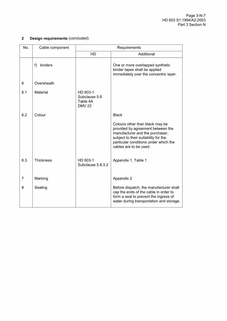
Page 3-N-7 HD 603 S1:1994/A2:2003
Part 3 Section N
2 Design requirements (concluded)
Requirements No. Cable component
HD Additional
f) binders
One or more overlapped synthetic binder tapes shall be applied immediately over the concentric layer.
6 6.1
Oversheath Material
HD 603-1 Subclause 5.8 Table 4A DMV 22
6.2 Colour Black Colours other than black may be provided by agreement between the manufacturer and the purchaser, subject to their suitability for the particular conditions under which the cables are to be used.
6.3
Thickness
HD 603-1 Subclause 5.8.3.2
Appendix 1, Table 1
7 Marking Appendix 2
8 Sealing Before dispatch, the manufacturer shall cap the ends of the cable in order to form a seal to prevent the ingress of water during transportation and storage.

Page 3-N-8 HD 603 S1:1994/A2:2003 Part 3 Section N
3 Test requirements 1 Routine tests No. Tests Requirements * Test methods
1
Conductor resistance: - phase - combined neutral/earth (3N-1,
3N-2, 3N-5 and 3N-6) - neutral (3N-3 and 3N-4) - earth continuity (3N-3 and 3N-4)
Appendix 1, Table 1
HD 605, Subclause 3.1.1
2 Voltage test on complete cable: - test voltage - acceptance criteria - duration
3,5 kV rms No failure 5 min
HD 605 Subclause 3.2.1
For types 3N-3 and 3N-4 an additional voltage test shall be applied between the bare earth continuity wires and the covered neutral wires in the concentric layer: - test voltage - acceptance criteria - duration
500 V d.c. No failure 1 min
3 Insulation resistance Size in mm2 4 16 25 and 35
MΩ per km at 20°C 8 6 5
After completion of voltage test and after application of 500 V d.c. for 1 min, the insulation resistance shall be measured between each phase conductor and between the phase conductors and all the wires in the concentric layer.
4
Spark test on insulation
No failure
HD 605 Subclause 3.6.1
5 Spark test on oversheath
No failure
HD 605 Subclause 3.6.1
6 Marking and measurement Appendix 2 Visual examination and measurement
* According to Section 2 Design requirements unless stated otherwise.

Page 3-N-9 HD 603 S1:1994/A2:2003
Part 3 Section N
3 Test requirements (continued)
2 Sample tests
No. Tests Requirements * Test methods 1
Phase conductor material and construction.
Clause 1
HD 605 Subclause 2.3.1.2 and by visual examination.
2 Concentric neutral/earth conductor material and construction.
Clause 5 Visual examination
3
Insulation: - application - thickness - colour
Clause 2 Appendix 1, Table 1 Subclause 2.3
Visual examination HD 605 Subclause 2.1.1 HD605 Subclause 2.5.4
4 Oversheath: - application - thickness
Clause 6 Appendix 1, Table 1
Visual examination HD 605 Subclause 2.1.2
5 Flame propagation on single cable
EN 50265-2-1 EN 50265-2-1
* According to Section 2 Design requirements unless stated otherwise.
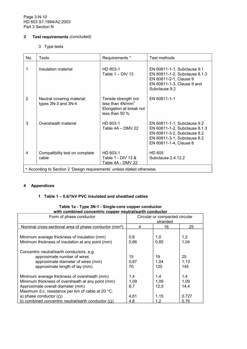
Page 3-N-10 HD 603 S1:1994/A2:2003 Part 3 Section N
3 Test requirements (concluded)
3 Type tests No. Tests Requirements * Test methods 1
Insulation material
HD 603-1 Table 1 DIV 13
EN 60811-1-1, Subclause 9.1 EN 60811-1-2, Subclause 8.1.3 EN 60811-2-1, Clause 9 EN 60811-1-3, Clause 9 and Subclause 9.2
2 Neutral covering material: types 3N-3 and 3N-4
Tensile strength not less than 4N/mm2 Elongation at break not less than 50 %
EN 60811-1-1
3 Oversheath material HD 603-1 Table 4A DMV 22
EN 60811-1-1, Subclause 9.2 EN 60811-1-2, Subclause 8.1.3 EN 60811-3-2, Subclause 8.2 EN 60811-3-1, Subclause 8.2 EN 60811-1-4, Clause 8
4 Compatibility test on complete cable
HD 603-1 Table 1 - DIV 13 & Table 4A - DMV 22
HD 605 Subclause 2.4.12.2
* According to Section 2 Design requirements unless stated otherwise. 4 Appendices
1 Table 1 0,6/1kV PVC insulated and sheathed cables
Table 1a - Type 3N-1 - Single-core copper conductor with combined concentric copper neutral/earth conductor
Form of phase conductor Circular or compacted circular stranded
Nominal cross-sectional area of phase conductor (mm²) 4 16 25 Minimum average thickness of insulation (mm) 0,8 1,0 1,2 Minimum thickness of insulation at any point (mm)
0,66 0,85 1,04
Concentric neutral/earth conductors, e,g: approximate number of wires 15 19 25 approximate diameter of wires (mm) 0,67 1,04 1,13 approximate length of lay (mm)
70 120 145
Minimum average thickness of oversheath (mm) 1,4 1,4 1,4 Minimum thickness of oversheath at any point (mm) 1,09 1,09 1,09 Approximate overall diameter (mm) 8,7 12,5 14,4 Maximum d.c. resistance per km of cable at 20 °C: a) phase conductor (Ω) 4,61 1,15 0,727 b) combined concentric neutral/earth conductor (Ω) 4,8 1,2 0,76

Page 3-N-11 HD 603 S1:1994/A2:2003
Part 3 Section N
4 Appendices
1 Table 1 (continued)
Table 1b - Type 3N-2 - Single-core aluminium conductor with combined concentric copper neutral/earth conductor
Form of phase conductor Circular solid Nominal cross-sectional area of phase conductor (mm2) 25 35
Minimum average thickness of insulation (mm) 1,2 1,2 Minimum thickness of insulation at any point (mm)
1,04 1,04
Concentric neutral/earth conductor, e,g: approximate number of wires 27 25 approximate diameter of wires (mm) 0,85 1,04 approximate length of lay (mm)
125 145
Minimum average thickness of oversheath (mm) 1,4 1,4 Minimum thickness of oversheath at any point (mm) 1,09 1,09 Approximate overall diameter (mm) 13,0 14,4 Maximum d.c. resistance per km of cable at 20 °C: a) phase conductor(Ω) 1,2 0,868 b) combined concentric neutral/earth conductor (Ω) 1,3 0,91
Table 1c - Type 3N-3 - Single-core copper conductor
with split concentric copper neutral/earth conductors
Form of phase conductor Circular or compacted circular stranded
Nominal cross-sectional area of phase conductor (mm2) 4 16 25 Minimum average thickness of insulation (mm) 0,8 1,0 1,2 Minimum thickness of insulation at any point (mm)
0,66 0,85 1,04
Approximate number and diameter of wires for concentric conductors, e,g:
Neutral no./mm 7/0,85 7/1,70 11/1,70 Earth continuity no./mm
3/1,35 4/2,25 4/2,25
Minimum average thickness of oversheath (mm) 1,4 1,4 1,5 Minimum thickness of oversheath at any point (mm) 1,09 1,09 1,17 Approximate overall diameter (mm) 9,8 15,0 18,3 Maximum d.c. resistance per km of cable at 20ºC: (a) phase conductor (Ω) 4,61 1,15 0,727 (b) neutral conductor (Ω) 4,8 1,2 0,76 (c) earth continuity conductor (Ω) 4,8 1,2 1,2
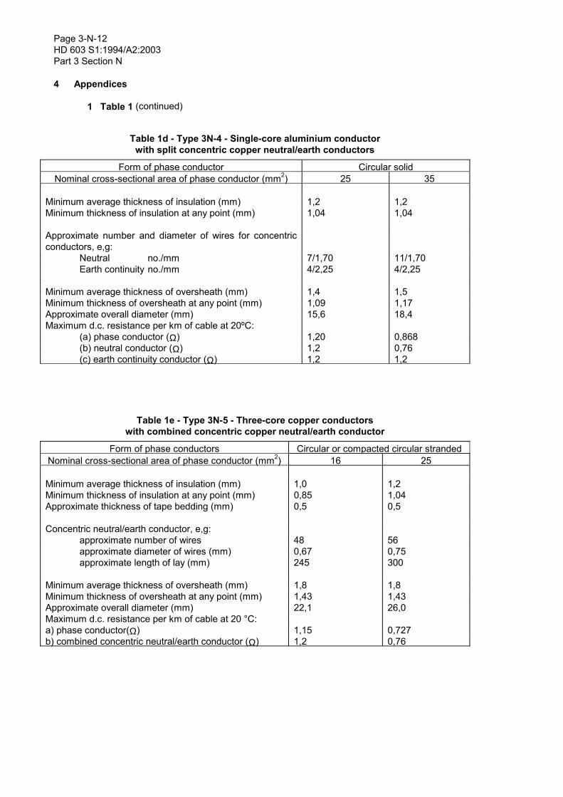
Page 3-N-12 HD 603 S1:1994/A2:2003 Part 3 Section N
4 Appendices
1 Table 1 (continued)
Table 1d - Type 3N-4 - Single-core aluminium conductor with split concentric copper neutral/earth conductors
Form of phase conductor Circular solid Nominal cross-sectional area of phase conductor (mm2) 25 35
Minimum average thickness of insulation (mm) 1,2 1,2 Minimum thickness of insulation at any point (mm)
1,04 1,04
Approximate number and diameter of wires for concentric conductors, e,g:
Neutral no./mm 7/1,70 11/1,70 Earth continuity no./mm
4/2,25 4/2,25
Minimum average thickness of oversheath (mm) 1,4 1,5 Minimum thickness of oversheath at any point (mm) 1,09 1,17 Approximate overall diameter (mm) 15,6 18,4 Maximum d.c. resistance per km of cable at 20ºC: (a) phase conductor (Ω) 1,20 0,868 (b) neutral conductor (Ω) 1,2 0,76 (c) earth continuity conductor (Ω) 1,2 1,2
Table 1e - Type 3N-5 - Three-core copper conductors with combined concentric copper neutral/earth conductor
Form of phase conductors Circular or compacted circular stranded Nominal cross-sectional area of phase conductor (mm2) 16 25 Minimum average thickness of insulation (mm) 1,0 1,2 Minimum thickness of insulation at any point (mm) 0,85 1,04 Approximate thickness of tape bedding (mm)
0,5 0,5
Concentric neutral/earth conductor, e,g: approximate number of wires 48 56 approximate diameter of wires (mm) 0,67 0,75 approximate length of lay (mm)
245 300
Minimum average thickness of oversheath (mm) 1,8 1,8 Minimum thickness of oversheath at any point (mm) 1,43 1,43 Approximate overall diameter (mm) 22,1 26,0 Maximum d.c. resistance per km of cable at 20 °C: a) phase conductor(Ω) 1,15 0,727 b) combined concentric neutral/earth conductor (Ω) 1,2 0,76

Page 3-N-13 HD 603 S1:1994/A2:2003
Part 3 Section N
4 Appendices
1 Table 1 (concluded)
Table 1f - Type 3N-6 - Three-core aluminium conductors with combined concentric copper neutral/earth conductor Form of phase conductors Circular solid
Nominal cross-sectional area of phase conductor (mm2) 25 35 Minimum average thickness of insulation (mm) 1,2 1,2 Minimum thickness of insulation at any point (mm) 1,04 1,04 Approximate thickness of tape bedding
0,5 0,5
Concentric neutral/earth conductor, e,g: approximate number of wires 45 61 approximate diameter of wires (mm) 0,67 0,67 approximate length of lay (mm)
270 300
Minimum average thickness of oversheath (mm) 1,8 1,8 Minimum thickness of oversheath at any point (mm) 1,43 1,43 Approximate overall diameter (mm) 24,1 26,2 Maximum d.c. resistance per km of cable at 20 °C: a) phase conductor (Ω) 1,2 0,868 b) combined concentric neutral/earth conductor (Ω) 1,3 0,91
4 Appendices 2 Marking
1 External Marking The external surface of all cables conforming to this standard shall be legibly marked with the following elements. Element Example of marking
a) Electric cable: ELECTRIC CABLE
b) Voltage designation: 600/1000V
c) Standard number: HD 603-3N
d) Manufacturers identification: XYZ
e) Number of cores, type and nominal area of phase conductors, e.g.
1) 3 x 25 AL shall indicate a three-core cable with a 25 mm2 aluminium phase conductor, 2) 1 x 25 shall indicate a single-core cable with a 25 mm2 copper phase conductor.
The marking of the elements a) to d) shall be by embossing or indenting on the oversheath.
Page 3-N-14 HD 603 S1:1994/A2:2003 Part 3 Section N
For cables with tabulated approximate overall diameters greater than 15 mm, elements a), b) and c) shall appear, in any sequence that is deemed neither to confuse nor conflict, on two or more primary lines along the axis of the cable, approximately equally spaced around the circumference of the cable. Elements d) and e) shall appear, together or separately, in any sequence that is deemed neither to confuse nor conflict, on either one of the primary lines, or on a secondary line or lines. For cables with tabulated approximate overall diameters of 15 mm or less, the elements shall be arranged as for cables of greater than 15 mm diameter, except that the marking for elements a), b) and c) shall appear on one or more primary lines. The letters and figures shall consist of upright block characters. The characters shall have a minimum height of 3 mm. The distance between the end of one element of marking and the beginning of the next identical element shall be not greater than 550 mm for elements a), b) and c), and not greater than 1 100 mm for elements d) and e).
2 Identification of year of manufacture A means of identifying the year of manufacture of the cable shall be provided throughout the length of the cable, either internally or by marking on the surface of the cable. If the identification mark is internal, the distance between the end of one mark and the beginning of the next mark shall be not greater than 550 mm. NOTE An identification thread may be used as an alternative to internal marking. If the identification is by marking on the surface it shall conform to the requirements given in 1d) and e) in respect of the maximum distance between marks.
3 The mark of an approval organization If the mark of an approval organisation is used, it shall be provided throughout the length of the cable, either as a mark on the surface of the cable, or as an identification thread, as specified by the approval organisation. If the mark is applied to the cable, it shall be on the surface in the form of the symbol(s) specified by the approval between marks.
4 Additional marking Where additional marking is made, it organisation, and shall conform to the requirements given in 1d) and e) in respect of the maximum distance shall be throughout the length of the cable, and on the external surface of the cable, or by means of a tape or thread within the cable, or by a combination of these methods. If the additional marking is applied to the surface of the cable it shall not render illegible the marking specified in 1 to 3. The additional marking, however made, shall be repeated at intervals not exceeding 1 100 mm.
5 End markings The end of each drum length of three-phase cable at which the sequence of core colours is clockwise shall be marked red. The other end shall be marked green.
Page 4-B-0 HD 603 S1:1994/A2:2003
Part 4 Section B
SECTION 4-B- CABLES WITH BRAIDED (TYPE 4B-1) OR HELICALLY APPLIED (TYPE 4B-2) ARMOUR
Replace Section 4-B
by the following A2 referred new Section 4-B:


Page 4-B-1 HD 603 S1:1994/A2:2003
Part 4 Section B
SECTION 4-B CABLES WITH BRAIDED (TYPE 4B-1) OR HELICALLY APPLIED (TYPE 4B-2) ARMOUR

Page 4-B-2 HD 603 S1:1994/A2:2003 Part 4 Section B
CONTENTS
1 General--------------------------------------------------------------------------------------------------------------------------- 3
2 Design requirements---------------------------------------------------------------------------------------------------------- 4
1 Conductor ------------------------------------------------------------------------------------------------------------- 4 1.1 Material 1.2 Main conductors 1.3 Mechanical properties of aluminium conductors 1.4 Auxiliary conductors 1.5 Conductor resistance 1.6 Permissible conductor types
2 Insulation -------------------------------------------------------------------------------------------------------------- 4 2.1 Material 2.2 Insulation thickness 2.3 Core identification
3 Assembly of cores and fillers ------------------------------------------------------------------------------------- 5 3.1 Assembly of cores 3.2 Fillers
4 Inner covering -------------------------------------------------------------------------------------------------------- 5 4.1 Thickness
5 Innersheath ----------------------------------------------------------------------------------------------------------- 5 5.1 Material 5.2 Thickness 5.3 Colour
6 Metallic layers -------------------------------------------------------------------------------------------------------- 6 6.1 Steel wire braid armour and protective earth conductor (type 4B-1) 6.2 Helically applied armour and protective earth conductor (type 4B-2)
7 Oversheath ----------------------------------------------------------------------------------------------------------- 6 7.1 Material 7.2 Thickness 7.3 Colour
8 Marking ---------------------------------------------------------------------------------------------------------------- 7 8.1 Indication of origin 8.2 Year of manufacture 8.3 Code designation 8.4 Continuity of marks 8.5 Durability 8.6 Legibility 8.7 Meter marking
9 Code designation---------------------------------------------------------------------------------------------------- 7
3 Test requirements ------------------------------------------------------------------------------------------------------------- 8 1 Routine tests --------------------------------------------------------------------------------------------------------- 8 2 Sample tests---------------------------------------------------------------------------------------------------------- 9 3 Type tests, electrical-----------------------------------------------------------------------------------------------12 4 Type tests, non-electrical -----------------------------------------------------------------------------------------13
4 Appendix (tables and Guide to use)--------------------------------------------------------------------------------------15
Page 4-B-3 HD 603 S1:1994/A2:2003
Part 4 Section B
REFERENCES
References are made in Section 4-B of HD 603, to other parts of this HD and to other Harmonization Documents and International Standards as follows:
HD 383 Conductors of insulated cables First supplement: Guide to the dimensional limits of circular conductors (endorsing IEC60228 and 60228A)
HD 605 Electric cables Additional test methods
EN 50265 (series) Common test methods for cables under fire conditions Test for resistance to vertical flame propagation for a single insulated conductor or cable
EN 60811 (series) Insulating and sheathing materials of electric cables Common test methods
In all cases reference to another HD or International Standard implies the latest edition of that document.
1 General
This standard specifies the construction, dimensions and test requirements of power cables with PVC-insulation, with a combined armour/protective earth conductor and with PVC sheath for rated voltage (U) of 1 kV for fixed installations 1). The cables may be provided with auxiliary cores.
(a) Insulating materials
The insulation covered by this standard shall consist of polyvinyl chloride and correspond to Table 1 of HD 603-1, compound DIV 8.
(b) Rated voltage
0,6/1 kV
Definitions: see HD 603-1, Subclause 2.3
(c) Highest rated temperature for the insulating compound
Normal operation 70 °C
(d) Sheathing material
Shall be suitable for the maximum rated conductor temperature. It shall consist of PVC and correspond to Table 4A of HD 603-1 - DMV 14.
(e) Test requirements
Type test (symbol T): validity of a type test is 5 years.
1) The cables in this section are service cables; an armoured main cable is not included in this HD. Instead of an armoured cable, the cable with concentric conductor as mentioned in Table 1 of Part 3, Section 1 can be applied. That cable type will also give some mechanical protection.

Page 4-B-4 HD 603 S1:1994/A2:2003 Part 4 Section B
2 Design requirements
No. Cable component Requirements
HD Additional
1 Conductor HD 603-1 Subclause 5.1
1.1 Material HD 603-1 Subclause 5.1.1
1.2 Main conductors HD 383
1.2.1 Composition and material a) circular solid aluminium and copper b) circular non-compacted stranded copper c) solid shaped aluminium
Table 1 Table 2 Table 1
The surface of aluminium conductors shall be smooth The surface of aluminium conductors shall be smooth
1.3 Mechanical properties of aluminium conductors (after cabling) a) tensile strength b) elongation at break
≥ 60 ≤ 120 N/mm2 ≥ 20 %
1.4 Auxiliary conductors HD 383
1.4.1 Composition and material a) circular solid copper
Table 1
1.5 Conductor resistance HD 383
1.6 Permissible conductor types Appendix, Tables 1 and 2
2 Insulation HD 603-1 Subclause 5.2
2.1 Material HD 603-1 Table 1 - DIV 8
2.2 Insulation thickness
2.2.1 Main cores a) specified value b) mean value c) minimum value
HD 603-1, Table 5
≥ specified value ≥ specified value - (0,1 + 10 % of specified value)
2.2.2 Auxiliary cores a) specified value b) minimum value
Appendix, Tables 1 and 2 ≥ specified value - (0,1 + 10 % of specified value)
2.3 Core identification HD 603-1, Clause 4
2.3.1 Main cores At the outer end of the cable on the drum, core colours shall be in a clockwise direction as follows: red, yellow, blue, yellow/blue.

Page 4-B-5 HD 603 S1:1994/A2:2003
Part 4 Section B
2 Design requirements (continued)
No. Cable component Requirements
HD Additional
2.3.2 Auxiliary cores Colours shall be as follows: a) four auxiliary cores of equal cross- sectional area: same as main cores b) two auxiliary cores: red, blue c) four auxiliary cores, two groups of different cross-sectional area: - larger cross-sectional area: red, blue - smaller cross-sectional area: yellow, yellow/blue
Each auxiliary core at the outer end of the cable on the cable drum, is situated on the right hand side of the main core with the same colour.
2.3.3 Colour combination yellow/blue
The colour stripes shall be applied to the core in longitudinal direction. The distribution of the colours shall be such that each colour covers at least 20 % of the surface of the core. On any 50 mm length of the outer side of the twisted cores both colours shall be discernable.
3 Assembly of cores HD 603-1 Subclause 5.3
Cores shall be laid up. Auxiliary cores shall be laid in the interstices of the main cores.
4 Filler
4.1 Centre filler HD 603-1 Subclause 5.4
A centre filler shall of non hygroscopic material be applied
4.2 Inner covering HD 603-1 Subclause 5.5
The inner covering shall be extruded and shall fill the interstices.
4.2.1 Thickness Thickness not specified
5 Innersheath HD 603-1 Subclause 5.6
5.1 Material HD 603-1 Table 4A DMV 14
5.2 Thickness a) specified value b) mean value c) minimum value
Appendix, Tables 1 and 2 ≥ specified value ≥ specified value - (0,1 mm + 15 % of specified value)
5.3 Colour Black or grey

Page 4-B-6 HD 603 S1:1994/A2:2003 Part 4 Section B
2 Design requirements (continued)
No. Cable component Requirements
HD Additional
6 Metallic layers
6.1 For cable type with steel wire braid armour/protective earth (PE) conductor (type 4B-1)
6.1 a The steel wire braid armour/PE-conductor shall be applied to the innersheath. It shall consist of braiding of galvanised steel wires with one or more continuous flat braided conductors of tinned copper wires underneath. The nominal diameter of the steel wires shall be 0,3 mm with a minimum of 0,27 mm. The nominal diameter of the copper wires shall be 0,25 mm with a minimum of 0,20 mm. The percentage of coverage of the innersheath by the steel wire braiding shall be ≥ 80 %. The nominal copper equivalent cross-sectional area of the steel wire braid armour/PE-conductor is given in Table 1, the total cross-sectional area of the flat braided copper conductor(s) shall be at last 80 % of this value. In case of more than one flat braided copper conductor, the cross-sectional area of each conductor shall be at least 1 mm²
The resistance of the steel wire braid armour/PE-conductor shall comply with the value given in Table 1. 6.1 b Additionally the resistance of the steel wire braid armour/ PE-conductor measured on a length of 20 m with the current source at one side connected to 5 % of the steel wires shall not exceed 2,5 % of the specified maximum value in Table 1.
6.2 For cable type with helically applied armour and protective earth (PE) conductor (type 4B-2)
6.2 a The combined armour/PE-conductor shall be applied helically to the innersheath and shall be manufactured of galvanised steel wires and annealed copper wires with a counter helix of copper tape. The minimum diameter of the steel and copper wires shall be 1,0 mm. The total covering on the innersheath by the steel and copper wires shall be ≥ 80 %. The gap between adjacent wires shall be ≤ 2 mm. The nominal copper equivalent cross-sectional area of the combined armour/PE-conductor is given in Table 2, the total cross-sectional area of the copper wires shall be at least 60 % of this value. The resistance of the combined armour/PE-conductor shall comply with the value given in Table 2. 6.2 b Additionally the resistance of the combined armour/earthing shield measured on a length of 20 m with the current source at one side connected to 2 steel wires shall not exceed 2,5 % of the specified maximum value in Table 2.
7 Oversheath HD 603-1 Subclause 5.8
7.1 Material HD 603-1 Table 4A - DMV 14
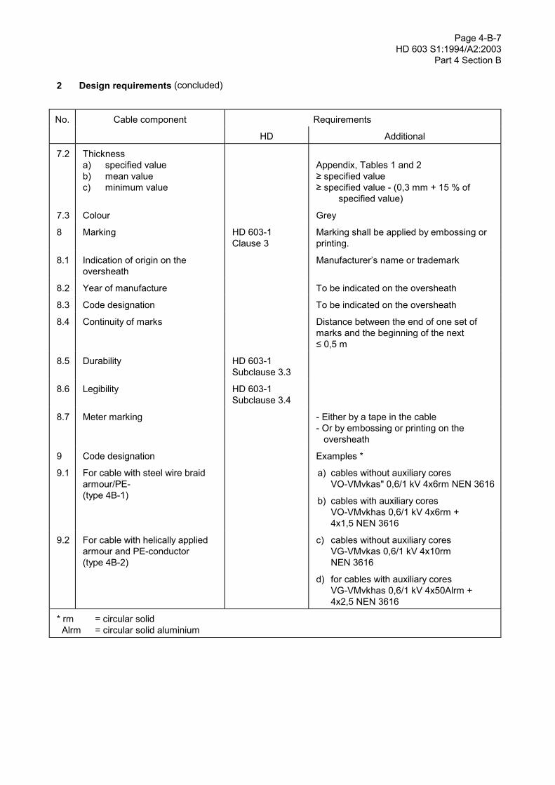
Page 4-B-7 HD 603 S1:1994/A2:2003
Part 4 Section B
2 Design requirements (concluded)
No. Cable component Requirements
HD Additional
7.2 Thickness a) specified value b) mean value c) minimum value
Appendix, Tables 1 and 2 ≥ specified value ≥ specified value - (0,3 mm + 15 % of specified value)
7.3 Colour Grey
8 Marking HD 603-1 Clause 3
Marking shall be applied by embossing or printing.
8.1 Indication of origin on the oversheath
Manufacturers name or trademark
8.2 Year of manufacture To be indicated on the oversheath
8.3 Code designation To be indicated on the oversheath
8.4 Continuity of marks Distance between the end of one set of marks and the beginning of the next ≤ 0,5 m
8.5 Durability HD 603-1 Subclause 3.3
8.6 Legibility HD 603-1 Subclause 3.4
8.7 Meter marking - Either by a tape in the cable - Or by embossing or printing on the oversheath
9 Code designation Examples *
9.1 For cable with steel wire braid armour/PE- (type 4B-1)
a) cables without auxiliary cores VO-VMvkas" 0,6/1 kV 4x6rm NEN 3616
b) cables with auxiliary cores VO-VMvkhas 0,6/1 kV 4x6rm + 4x1,5 NEN 3616
9.2 For cable with helically applied armour and PE-conductor (type 4B-2)
c) cables without auxiliary cores VG-VMvkas 0,6/1 kV 4x10rm NEN 3616
d) for cables with auxiliary cores VG-VMvkhas 0,6/1 kV 4x50Alrm + 4x2,5 NEN 3616
* rm = circular solid Alrm = circular solid aluminium

Page 4-B-8 HD 603 S1:1994/A2:2003 Part 4 Section B
3 Test requirements 1 Routine tests
1 2 3 4
No. Tests Requirements * Test methods
1 Electrical resistance
1.1 Conductor resistance Ref. no. 1.5 HD 605, Subclause 3.1.1
1.2 Resistance of steel wire braid armour and protective earth conductor (type 4B-1)
Ref. no. 6.1 and Table I
HD 605, Subclause 3.1.3.1
1.3 Resistance of helically applied armour and protective earth conductor (type 4B-2)
Ref. no. 6.2 and Table 2
HD 605, Subclause 3.1.3.2
2 High voltage test (on complete cable) ** - Test voltage - Duration of test, - Test result
4 kV a.c. 5 min per core No breakdown
Four core cable without auxiliary cores: a) red and blue yellow, yellow/blue and earth b) yellow and yellow/blue red, blue and earth c) two adjacent cores remaining cores and earth
Four core cable with auxiliary cores: a) red and blue yellow, yellow/blue, all auxiliary cores and earth b) yellow and yellow/blue red, blue, all auxiliary cores and earth c) two adjacent cores and all auxiliary cores remaining cores and earth
3 Constructional characteristics Section 2 and HD 603-1, Clause 5
3.1 General construction of cable Visual inspection
3.2 Core identification Ref. no. 2.3
3.3 Marking HD 603-1, Clause 3 and Ref. no. 8
* According to Section 2 Design requirements unless stated otherwise. ** Concentric conductor or armour, if present, shall be connected to earth.

Page 4-B-9 HD 603 S1:1994/A2:2003
Part 4 Section B
3 Test requirements (continued) 2 Sample tests
Frequency and sampling category: See ref. no. 7.1.1 of the sample tests See ref. no. 7.1.2 of the sample tests Repetition of sample tests in case of noncompliance: See ref. no. 7.2
1 2 3 4
No. Tests Requirements * Test methods
1 Aluminium conductors
1.1 - Condition of surface Ref. no. 1.2.1 a and c Visual inspection
1.2 - Tensile properties Ref. no. 1.3 HD 605, Subclause 2.3.1.2
2 Insulation Tests applicable to main and auxiliary cores
2.1 - Thickness Ref. no. 2.2 EN 60811-1-1, Subclause 8.1 and HD 605, Subclause 2.1.1
2.2 - Tensile properties before ageing
HD 603-1 Table 1 - DIV 8
EN 60811-1-1 Subclause 9.1
Tests 2.3 2.7 applicable to main cores only
2.3 - Application to conductor HD 603-1 Subclause 5.2.2
Inspection and manual test
2.4 - Pressure test at 80 °C HD 603-1 Table 1 - DIV 8
EN 60811-3-1 Subclause 8.1
2.5 - Cold bending test at -15 °C (for diameter ≤ 12,5 mm)
HD 603-1 Table 1 - DIV 8
EN 60811-1-4 Subclause 8.1
2.6 - Cold elongation test at -15 °C (for diameter > 12,5 mm)
HD 603-1 Table 1 - DIV 8
EN 60811-1-4 Subclause 8.3
2.7 - Heat shock test HD 603-1 Table 1 - DIV 8
EN 60811-3-1 Subclause 9.1
3 Innersheath
3.1 - Thickness Ref. no. 5.2 EN 60811-1-1, Subclause 8.2 and HD 605, Subclause 2.1.2
3.2 - Tensile properties before ageing
HD 603-1 Table 3 - DMV 14
EN 60811-1-1 Subclause 9.2
4 Steel wire braid armour/PE-conductor (type 4B-1)
4.1 Constructional characteristics Ref. no. 6.1 Visual inspection and measurement
4.2 Coverage density of braid Ref. no. 6.1 HD 605, Subclause 2.1.7
* According to Section 2 Design requirements unless stated otherwise.

Page 4-B-10 HD 603 S1:1994/A2:2003 Part 4 Section B
3 Test requirements (continued)
2 Sample tests (continued)
Frequency and sampling category: See ref. no. 7.1.1 of the sample tests See ref. no. 7.1.2 of the sample tests Repetition of sample tests because: See ref. no. 7.2
1 2 3 4
No. Tests Requirements * Test methods
5 Helically applied armour and PE-conductor (type 4B-2)
5.1 Constructional characteristics Ref. no. 6.2 Visual inspection and measurement
6 Oversheath
6.1 - Thickness Ref. no. 7.2 EN 60811-1-1, Subclause 8.2 HD 605, Subclause 2.1.2
6.2 - Tensile properties before ageing
HD 603-1 Table 4A - DMV 14
EN 60811-1-1, Subclause 9.2
6.3 - Pressure test at 80 °C " EN 60811-3-1, Subclause 8.2
6.4 - Cold elongation test at -15 °C
EN 60811-1-4, Subclause 8.4
6.5 - Cold impact test at -15 °C EN 60811-1-4, Subclause 8.5
6.6 Heat shock test at 150 °C EN 60811-3-1, Subclause 9.2
* According to Section 2 Design requirements unless stated otherwise.
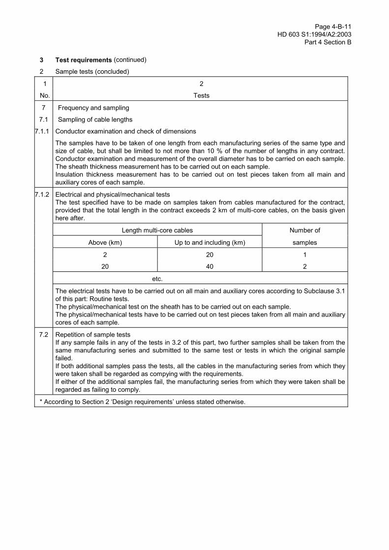
Page 4-B-11 HD 603 S1:1994/A2:2003
Part 4 Section B
3 Test requirements (continued) 2 Sample tests (concluded)
1 2
No. Tests
7 Frequency and sampling
7.1 Sampling of cable lengths
7.1.1 Conductor examination and check of dimensions
The samples have to be taken of one length from each manufacturing series of the same type and size of cable, but shall be limited to not more than 10 % of the number of lengths in any contract.Conductor examination and measurement of the overall diameter has to be carried on each sample.The sheath thickness measurement has to be carried out on each sample. Insulation thickness measurement has to be carried out on test pieces taken from all main and auxiliary cores of each sample.
7.1.2 Electrical and physical/mechanical tests The test specified have to be made on samples taken from cables manufactured for the contract, provided that the total length in the contract exceeds 2 km of multi-core cables, on the basis given here after.
Length multi-core cables Number of
Above (km) Up to and including (km) samples
2 20 1
20 40 2
etc.
The electrical tests have to be carried out on all main and auxiliary cores according to Subclause 3.1 of this part: Routine tests. The physical/mechanical test on the sheath has to be carried out on each sample. The physical/mechanical tests have to be carried out on test pieces taken from all main and auxiliary cores of each sample.
7.2 Repetition of sample tests If any sample fails in any of the tests in 3.2 of this part, two further samples shall be taken from the same manufacturing series and submitted to the same test or tests in which the original sample failed. If both additional samples pass the tests, all the cables in the manufacturing series from which they were taken shall be regarded as compying with the requirements. If either of the additional samples fail, the manufacturing series from which they were taken shall be regarded as failing to comply.
* According to Section 2 Design requirements unless stated otherwise.
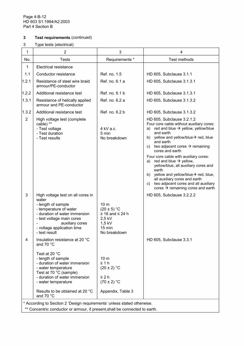
Page 4-B-12 HD 603 S1:1994/A2:2003 Part 4 Section B
3 Test requirements (continued) 3 Type tests (electrical)
1 2 3 4
No. Tests Requirements * Test methods
1 Electrical resistance
1.1 Conductor resistance Ref. no. 1.5 HD 605, Subclause 3.1.1
1.2.1 Resistance of steel wire braid armour/PE-conductor
Ref. no. 6.1 a HD 605, Subclause 3.1.3.1
1.2.2 Additional resistance test Ref. no. 6.1 b HD 605, Subclause 3.1.3.1
1.3.1 Resistance of helically applied armour and PE-conductor
Ref. no. 6.2 a HD 605, Subclause 3.1.3.2
1.3.2 Additional resistance test Ref. no. 6.2 b HD 605, Subclause 3.1.3.2
2 High voltage test (complete cable) ** - Test voltage - Test duration - Test results
4 kV a.c. 5 min No breakdown
HD 605, Subclause 3.2.1.2 Four core cable without auxiliary cores: a) red and blue yellow, yellow/blue and earth b) yellow and yellow/blue red, blue and earth c) two adjacent cores remaining cores and earth Four core cable with auxiliary cores: a) red and blue yellow, yellow/blue, all auxiliary cores and earth b) yellow and yellow/blue red, blue, all auxiliary cores and earth c) two adjacent cores and all auxiliary cores remaining cores and earth
3 High voltage test on all cores in water - length of sample - temperature of water - duration of water immersion - test voltage main cores - auxiliary cores - voltage application time - test result
10 m (20 ± 5) °C ≥ 16 and ≤ 24 h 2,5 kV 1,5 kV 15 min No breakdown
HD 605, Subclause 3.2.2.2
4 Insulation resistance at 20 °C and 70 °C Test at 20 °C - length of sample - duration of water immersion - water temperature Test at 70 °C (sample) - duration of water immersion - water temperature Results to be obtained at 20 °C and 70 °C
10 m ≥ 1 h (20 ± 2) °C ≥ 2 h (70 ± 2) °C Appendix, Table 3
HD 605, Subclause 3.3.1
* According to Section 2 Design requirements unless stated otherwise. ** Concentric conductor or armour, if present,shall be connected to earth.

Page 4-B-13 HD 603 S1:1994/A2:2003
Part 4 Section B
3 Test requirements (continued)
4 Type tests (non-electrical)
1 2 3 4
No. Tests Requirements * Test methods
1 Constructional characteristics Section 2 and HD 603-1, Clause 5
Visual inspection
1.1 General construction of cable
1.2 Core identification Ref. no. 2.3
1.3 Marking Ref. no. 8 and HD 603-1, Clause 3
2 Aluminium conductors
2.1 Condition of surface Ref. no. 1.2.1 a) and c)
Visual inspection
2.2 Tensile properties Ref. no. 1.3 HD 605, Subclause 2.3.1.2
3 Tests on insulation of main conductors
3.1 Application to conductor HD 603-1 Subclause 5.2.2
Inspection and manual test
3.2 Thickness Ref. no. 2.2 EN 60811-1-1, Subclause 8.1 HD 605, Subclause 2.1.1
3.3 Mechanical properties - before ageing - after ageing
HD 603-1 Table 1 - DIV 8
EN 60811-1-1, Subclause 9.1 EN 60811-1-2, Subclause 8.1.3.1 and EN 60811-1-1, Subclause 9.1
3.4 Mechanical properties after ageing of complete cable
" EN 60811-1-2, Subclause 8.1.4 and EN 60811-1-1, Subclause 9.1
3.5 Loss of mass " EN 60811-3-2, Subclause 8.1
3.6 Pressure test at 80 °C EN 60811-3-1, Subclause 8.1
3.7 Cold bending test at -15 °C (for diameter ≤ 12,5 mm)
EN 60811-1-4, Subclause 8.1
3.8 Cold elongation test at -15 °C (for diameter > 12,5 mm)
HD 603-1 Table 1 - DIV 8
EN 60811-1-4, Subclause 8.3
3.9 Heat shock test EN 60811-3-1, Subclause 9.1
3.10 Water absorption " EN 60811-1-3, Subclause 9.1
4 Tests on insulation of auxiliary conductors
4.1 Thickness Ref. no. 2.2 EN 60811-1-1, Subclause 8.1 and HD 605, Subclause 2.1.1
4.2 Mechanical properties - before ageing
HD 603-1 Table 1 - DIV 8
EN 60811-1-1, Subclause 9.1
* According to Section 2 Design requirements" unless stated otherwise.

Page 4-B-14 HD 603 S1:1994/A2:2003 Part 4 Section B
3 Test requirements (concluded) 4 Type tests (non-electrical, concluded)
1 2 3 4
No. Tests Requirements * Test methods
5 Tests on innersheath
5.1 Thickness Ref. no. 5.2 EN 60811-1-1, Subclause 8.2 and HD 605, Subclause 2.1.2
5.2 Mechanical properties - before ageing - after ageing
HD 603-1 Table 4A - DMV 14
EN 60811-1-1, Subclause 9.2 EN 60811-1-2, Subclause 8.1 and EN 60811-1-1, Subclause 9.2
5.3 Mechanical properties after ageing of complete cable
" EN 60811-1-2, Subclause 8.1.4 and EN 60811-1-2 2, Subclause 9.2
6 Steel wire braid armour / PE-conductor (type 4B-1)
6.1 Constructional characteristics Ref. no. 6.1 Visual inspection and measurement
6.2 Coverage density of braid Ref. no. 6.1 HD 605, Subclause 2.1.7
7 Helically applied armour and PE-conductor (type 4B-2)
7.1 Constructional characteristics Ref. no. 6.2 Visual inspection and measurement
8 Tests on oversheath
8.1 Thickness Ref. no. 7.2 EN 60811-1-1 Subclause 8.2 and HD 605, Subclause 2.1.2
8.2 Mechanical properties - before ageing - after ageing
HD 603-1 Table 4A - DMV 14
EN 60811-1-1, Subclause 9.2 EN 60811-1-2, Subclause 8.1 and EN 60811-1-1, Subclause 9.2
8.3 Mechanical properties after ageing of complete cable
" EN 60811-1-2- Subclause 8.1.4 and EN 60811-1-1, Subclause 9.2
8.4 Loss of mass " EN 60811-3-2, Subclause 8.2
8.5 Pressure test at 80 °C EN 60811-3-1 Subclause 8.2
8.6 Cold elongation test at -15 °C EN 60811-1-4 Subclause 8.4
8.7 Cold impact test at -15 °C EN 60811-1-4, Subclause 8.5
8.8 Heat shock test at 150 °C EN 60811-3-1, Subclause 9.2
9 Bending test on complete cable at 0 °C, followed by voltage test of 7,5 kV for 10 min
No breakdown and no visible damage
HD 605, Subclause 2.4.1 1, but at (0 ± 2) °C, 3 complete turns and cylinder diameter 12 x cable diameter
10 Flame retardance test on complete cable
EN 50265-1 and EN 50265-2-1
EN 50265-1 and EN 50265-2-1
* According to Section 2 Design requirements" unless stated otherwise.
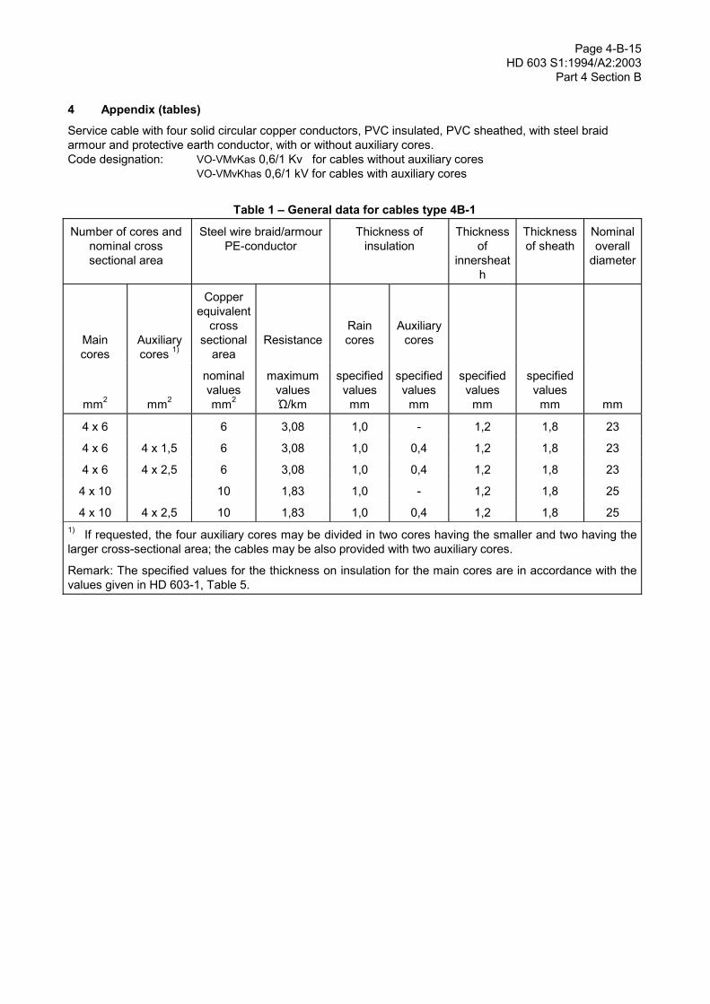
Page 4-B-15 HD 603 S1:1994/A2:2003
Part 4 Section B
4 Appendix (tables) Service cable with four solid circular copper conductors, PVC insulated, PVC sheathed, with steel braid armour and protective earth conductor, with or without auxiliary cores. Code designation: VO-VMvKas 0,6/1 Kv for cables without auxiliary cores VO-VMvKhas 0,6/1 kV for cables with auxiliary cores
Table 1 General data for cables type 4B-1
Number of cores and nominal cross sectional area
Steel wire braid/armourPE-conductor
Thickness of insulation
Thickness of
innersheath
Thickness of sheath
Nominal overall
diameter
Main cores
Auxiliary cores 1)
Copper equivalent
cross sectional
area
Resistance
Rain cores
Auxiliary cores
mm2
mm2
nominal values mm2
maximum values Ώ/km
specified values
mm
specifiedvalues
mm
specified values
mm
specified values
mm
mm
4 x 6 6 3,08 1,0 - 1,2 1,8 23
4 x 6 4 x 1,5 6 3,08 1,0 0,4 1,2 1,8 23
4 x 6 4 x 2,5 6 3,08 1,0 0,4 1,2 1,8 23
4 x 10 10 1,83 1,0 - 1,2 1,8 25
4 x 10 4 x 2,5 10 1,83 1,0 0,4 1,2 1,8 25 1) If requested, the four auxiliary cores may be divided in two cores having the smaller and two having the larger cross-sectional area; the cables may be also provided with two auxiliary cores.
Remark: The specified values for the thickness on insulation for the main cores are in accordance with the values given in HD 603-1, Table 5.
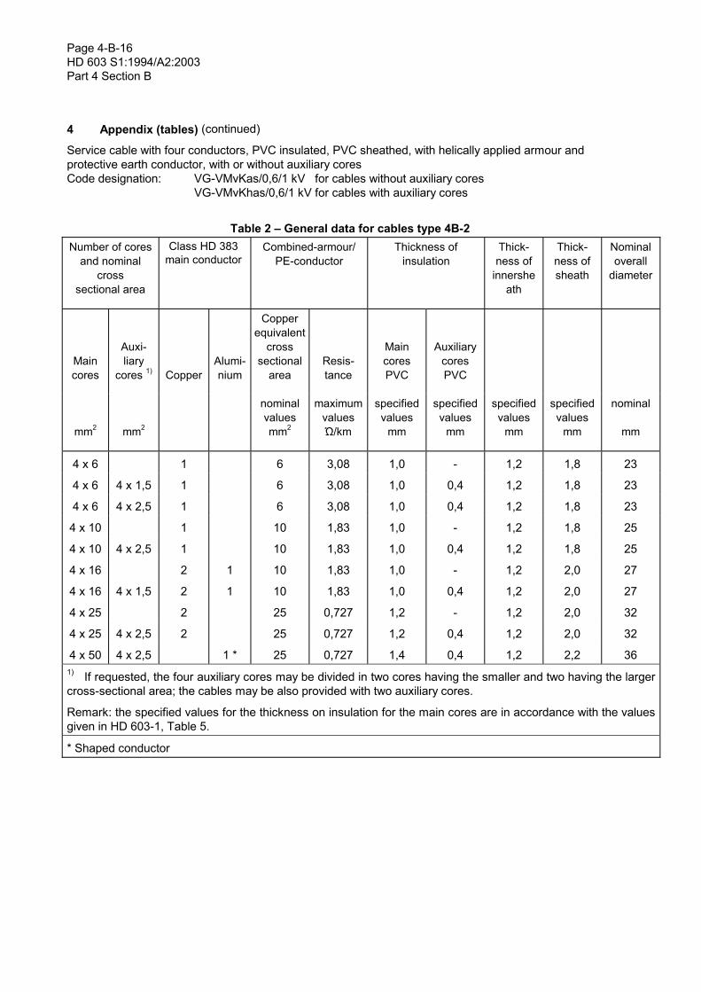
Page 4-B-16 HD 603 S1:1994/A2:2003 Part 4 Section B
4 Appendix (tables) (continued) Service cable with four conductors, PVC insulated, PVC sheathed, with helically applied armour and protective earth conductor, with or without auxiliary cores Code designation: VG-VMvKas/0,6/1 kV for cables without auxiliary cores VG-VMvKhas/0,6/1 kV for cables with auxiliary cores
Table 2 General data for cables type 4B-2 Number of cores
and nominal cross
sectional area
Class HD 383 main conductor
Combined-armour/ PE-conductor
Thickness of insulation
Thick-ness of
innersheath
Thick-ness of sheath
Nominal overall
diameter
Main cores
Auxi-liary
cores 1)
Copper
Alumi-nium
Copper equivalent
cross sectional
area
Resis-tance
Main cores PVC
Auxiliary cores PVC
mm2
mm2
nominal values mm2
maximumvalues Ώ/km
specified values
mm
specified values
mm
specified values
mm
specified values
mm
nominal
mm
4 x 6 1 6 3,08 1,0 - 1,2 1,8 23
4 x 6 4 x 1,5 1 6 3,08 1,0 0,4 1,2 1,8 23
4 x 6 4 x 2,5 1 6 3,08 1,0 0,4 1,2 1,8 23
4 x 10 1 10 1,83 1,0 - 1,2 1,8 25
4 x 10 4 x 2,5 1 10 1,83 1,0 0,4 1,2 1,8 25
4 x 16 2 1 10 1,83 1,0 - 1,2 2,0 27
4 x 16 4 x 1,5 2 1 10 1,83 1,0 0,4 1,2 2,0 27
4 x 25 2 25 0,727 1,2 - 1,2 2,0 32
4 x 25 4 x 2,5 2 25 0,727 1,2 0,4 1,2 2,0 32
4 x 50 4 x 2,5 1 * 25 0,727 1,4 0,4 1,2 2,2 36 1) If requested, the four auxiliary cores may be divided in two cores having the smaller and two having the larger cross-sectional area; the cables may be also provided with two auxiliary cores.
Remark: the specified values for the thickness on insulation for the main cores are in accordance with the values given in HD 603-1, Table 5.
* Shaped conductor
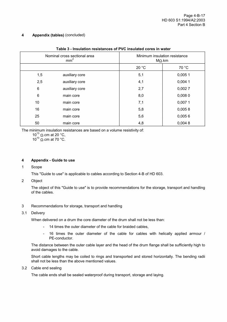
Page 4-B-17 HD 603 S1:1994/A2:2003
Part 4 Section B
4 Appendix (tables) (concluded)
Table 3 - Insulation resistances of PVC insulated cores in water
Nominal cross sectional area mm2
Minimum insulation resistance MΩ.km
20 °C 70 °C
1,5 auxiliary core 5,1 0,005 1
2,5 auxiliary core 4,1 0,004 1
6 auxiliary core 2,7 0,002 7
6 main core 8,0 0,008 0
10 main core 7,1 0,007 1
16 main core 5,8 0,005 8
25 main core 5,6 0,005 6
50 main core 4,8 0,004 8
The minimum insulation resistances are based on a volume resistivity of: 1013 Ω.cm at 20 °C, 1010 Ω.cm at 70 °C.
4 Appendix - Guide to use 1 Scope
This "Guide to use" is applicable to cables according to Section 4-B of HD 603.
2 Object
The object of this "Guide to use" is to provide recommendations for the storage, transport and handling of the cables.
3 Recommendations for storage, transport and handling
3.1 Delivery
When delivered on a drum the core diameter of the drum shall not be less than:
- 14 times the outer diameter of the cable for braided cables,
- 16 times the outer diameter of the cable for cables with helically applied armour / PE-conductor.
The distance between the outer cable layer and the head of the drum flange shall be sufficiently high to avoid damages to the cable.
Short cable lengths may be coiled to rings and transported and stored horizontally. The bending radii shall not be less than the above mentioned values.
3.2 Cable end sealing
The cable ends shall be sealed waterproof during transport, storage and laying.

Page 4-B-18 HD 603 S1:1994/A2:2003 Part 4 Section B
4 Appendix - Guide to use (continued)
3.3 Transport
For the transport of filled up cable reels only suitable carriers shall be used.
Cables stored at temperatures which fall below those recommended for installation shall not be subject to any mechanical stress including shocks, impact, bending and torsion.
It shall be prevented that drum flanges come in touch with the cable of another drum.
For loading and unloading of cable drums suitable lifting and hoisting equipment shall be used; never drop a drum on the ground or on a buffer.
See also relevant figures.
Filled up cable drums shall be rolled only on short distances over plain solid ground in the direction indicated.
The cable end shall be tightened.
3.4 Lowest temperature for cable laying and installation
Insulation and sheath of PVC is liable to cracking at low temperatures in case of strokes against the cable or excessive bending. Care should therefore be taken during transport, laying and installation.
Lowest temperature of cable during installation is 0 °C under normal conditions of care.
This temperature is valid for the cable itself and not for the environment. If possible, the temperature of the cable shall be raised to at least + 10 °C before laying, e.g. in a heated building, to facilitate handling and to reduce the risk of damages.
3.5 Pulling loads
It is assumed that the cable route is well designed for the laying procedure with well established curves and a sufficient number of cable rollers. Special attention shall be paid to the required minimum bending radii (see Subclause 3.6 of this appendix). The pulling forces shall be permanently supervised during the pull-in procedure.
The pulling force shall be evenly divided over the main conductors.
The maximum pulling force (P) shall be calculated as follows:
P = S σ
where P is in N
σ is maximum tensile stress in conductor, viz.
50 N / mm2 for copper conductor
30 N / mm2 for aluminium conductors
S is total cross-sectional area in mm2 of the main conductors (ignoring screens, concentric conductors and auxiliary conductors).
In case of using a cable stocking, the total pulling force shall not exceed 1 000 N.
3.6 Bending radius
During installation the internal bending radius of the cable shall not be smaller than 10 D, where D is the overall diameter of the cable. This value may be reduced to 8 D in case of a careful, one single time bending of the cable end.
Bending nearby the temperature limits given in Subclause 3.4 of this appendix should be carried out extra carefully.
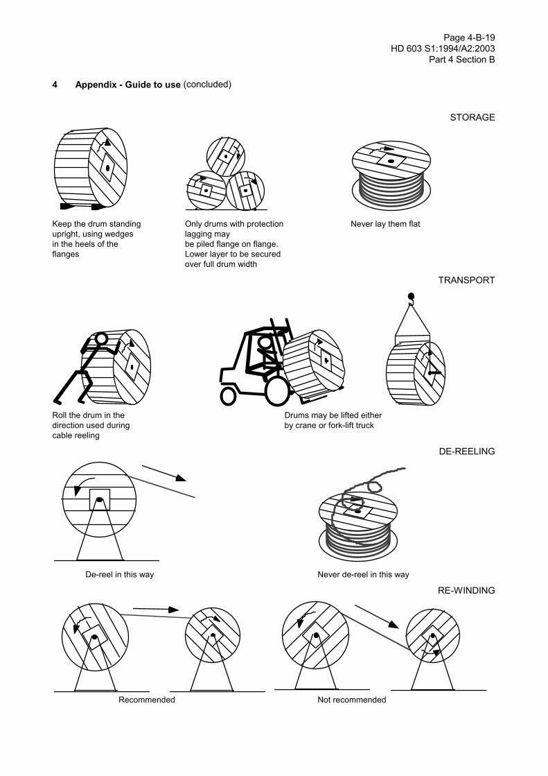
Page 4-B-19 HD 603 S1:1994/A2:2003
Part 4 Section B
4 Appendix - Guide to use (concluded)
STORAGE
Keep the drum standing Only drums with protection Never lay them flat upright, using wedges lagging may in the heels of the be piled flange on flange. flanges Lower layer to be secured over full drum width
TRANSPORT
Roll the drum in the Drums may be lifted either direction used during by crane or fork-lift truck cable reeling
DE-REELING
De-reel in this way Never de-reel in this way
RE-WINDING
Recommended Not recommended

Page 4-B-20 HD 603 S1:1994/A2:2003 Part 4 Section B
BLANK PAGE

Page 5-D-0 HD 603 S1:1994/A2:2003
Part 5 Section D
SECTION 5-D - CABLES WITH (TYPE 5D-1) AND WITHOUT (TYPE 5D-2) CONCENTRIC CONDUCTOR
Replace page
5-D-3
by the following A2 referred new page
5-D-3:


Page 5-D-3 HD 603 S1:1994/A2:2003
Part 5 Section D
2 Design requirements
No. Cable component Requirements
HD Additional
1 Conductor HD 603-1 Subclause 5.1
1.1 Material HD 603-1 Subclause 5.1.1
1.2 Design a) Multi-core cabling cross- section of 16 mm2 and 25 mm2
b) Multi-core cabling other cross sections c) Single-core cables
HD 383 16 mm2: round, class 1 solid or class 2 stranded 25 mm2: class 2 stranded, compacted round or compacted sector-shaped Class 2, compacted sector-shaped Class 2, round stranded and compacted
1.3 Conductor Resistance HD 383 Appendix, Table 1
2 Insulation HD 603-1 Subclause 5.2
2.1 Material HD 603-1 Tables 2A type DIX6
2.2 Insulation thickness a) nominal value b) mean value c) minimum value
Appendix, Table 2 ≥ nominal value ≥ nominal value - (0,1 mm + 10 % of nominal value)
NOTE The thickness of any separator on the conductor or over the insulation shall not be included in the thickness of the insulation.
2.3 Core identification a) colour combination green/yellow b) order
HD 603-1 Subclause 4.1
Appendix, Table 5 Appendix, Table 5
3 Assembly of cores
3.1 Assembly Cores of multi-core cables shall be laid-up and have a lapped or extruded inner covering.
3.2 Interstice fillers HD 603-1 Subclause 5.4
Yarn of appropriate material or other means to ensure that construction is sufficiently compact
4 Inner covering HD 603-1 Subclause 5.5
Material compatible with others and with service temperature
4.1 Design Lapped or extruded
4.2 Thickness Appendix, Table 3


Page 5-G-0 HD 603 S1:1994/A2:2003
Part 5 Section G
SECTION 5-G - CABLES WITH (TYPE 5G-1) OR WITHOUT (TYPE 5G-2) CONCENTRIC CONDUCTOR
Replace Section 5-G
by the following referred A2 new Section 5-G:


Page 5-G-1 HD 603 S1:1994/A2:2003
Part 5 Section G
SECTION 5-G - CABLES WITH (TYPE 5G-1) OR WITHOUT (TYPE 5G-2) CONCENTRIC CONDUCTOR

Page 5-G-2 HD 603 S1:1994/A2:2003 Part 5 Section G
CONTENTS
1 General--------------------------------------------------------------------------------------------------------------------------- 4
2 Design requirements---------------------------------------------------------------------------------------------------------- 5
1 Conductor ------------------------------------------------------------------------------------------------------------- 5
1.1 Material 1.2 Dimensions of stranded circular conductors 1.3 Dimensions of sector-shaped conductors 1.4 Tensile strength for aluminium conductors 1.5 Crossing points for stranded conductors 1.6 Conductor resistance 1.7 Permissible conductor types 1.8 Conductors with reduced cross-sectional area 1.9 Additional core with 1,5 mm² conductor 1.10 Tape over conductor
2 Insulation -------------------------------------------------------------------------------------------------------------- 6
2.1 Material 2.2 Insulation thickness 2.3 Core identification 2.4 Separation of sheath and insulation
3 Assembly of cores--------------------------------------------------------------------------------------------------- 6
3.1 Assembly 3.2 Interstice fillers
4 Inner covering -------------------------------------------------------------------------------------------------------- 7
4.1 Design 4.2 Thickness 4.3 Tape over inner covering
5 Concentric conductor----------------------------------------------------------------------------------------------- 7
5.1 Design 5.2 DC resistance 5.3 Copper binder tapes 5.4 Clearance between adjacent wires
6 Outer sheath---------------------------------------------------------------------------------------------------------- 8
6.1 Material 6.2 Colour 6.3 Thickness
7 Outer diameter ------------------------------------------------------------------------------------------------------- 8
8 Marking on outer sheath------------------------------------------------------------------------------------------- 8 8.1 Indication of origin and year of manufacturing 8.2 Code designation of design and rated voltage U (kV) 8.3 Continuity of marks 8.4 Durability 8.5 Legibility 8.6 Compliance with HD 603-5G 8.7 Meter marking
9 Type designation ---------------------------------------------------------------------------------------------------- 9

Page 5-G-3 HD 603 S1:1994/A2:2003
Part 5 Section G
3 Test requirements ------------------------------------------------------------------------------------------------------------- 9
1 Routine tests ------------------------------------------------------------------------------------------------- 9
2 Sample tests-------------------------------------------------------------------------------------------------10
3 Type tests, electrical---------------------------------------------------------------------------------------11
4 Type tests, non-electrical---------------------------------------------------------------------------------11
5 Electrical tests after installation -------------------------------------------------------------------------13
4 Guide to use -------------------------------------------------------------------------------------------------------------------13
1 Recommendations for use
2 Recommendations for storage and transport
3 Recommendations for cable laying
4 Recommendations for fault detection
5 Current-carrying capacity (recommended values) --------------------------------------------------------------------17
6 Appendix (tables) -------------------------------------------------------------------------------------------------------------19
REFERENCES References are made in Section 5-G of HD 603, to other parts of this HD and to other Harmonization Documents and International Standards as follows:
HD 383 Conductors of insulated cables First supplement: Guide to the dimensional limits of circular conductors (endorsing IEC 60228 and 60228A)
HD 402 Standard colours for insulation for low-frequency cables and wires
HD 605 Electric cables Additional test methods
EN 50265 (series) Common test methods for cables under fire conditions Test for resistance to vertical flame propagation for a single insulated conductor or cable
EN 60811 (series) Insulating and sheathing materials of electric cables Common test methods
IEC 60183 Guide to the selection of high-voltage cables
IEC 60502-1 Power cables with extruded insulation and their accessories for rated voltages from 1 kV (Um = 1,2 kV) up to 30 kV (Um = 36 kV) Part 1: Cables for rated voltages from 1 kV (Um = 1,2 kV) and 3 kV (Um = 3,6 kV)
In all cases reference to another HD or International Standard implies the latest edition of that document.
Page 5-G-4 HD 603 S1:1994/A2:2003 Part 5 Section G
1 General
This standard specifies the construction, dimensions and test requirements of power cables with XLPE-insulation and with (type 5G-1) or without (type 5G-2) concentric conductor for rated voltage Uo/U of 0,6/1 kV.
(a) Insulating materials
The insulation covered by this standard shall consist of cross-linked polyethylene and correspond to HD 603-1, Table 2A , DIX 3.
(b) Rated voltage
0,6/1 kV
(i) Definitions: see HD 603-1, Subclause 2.3 and HD 603-5G, Section 4, Subclause 1.2.
(ii) Cables covered by this standard are suitable to Category B according to IEC 60183. The duration of an earth fault may not exceed 8 h. the total duration of earth faults in any year should not exceed 125 h.
(c) Highest rated temperatures for the insulating compound
(i) Normal operation 90 °C
(ii) Short-circuit (5 sec max. duration) 250 °C
(d) Sheathing material
The sheathing materials shall be suitable for the maximum rated temperature. It shall consist of PVC or PE and correspond to HD 603-1, Tables 4A or 4B, DMV 6 or DMP 2.
(e) Test conditions
See HD 605

Page 5-G-5 HD 603 S1:1994/A2:2003
Part 5 Section G
2 Design requirements
No. Cable component Requirements
HD Additional
1 Conductor HD 603-1 Subclause 5.1
1.1 Material a) General b) Purity of aluminium
HD 603-1 Subclause 5.1.1
Copper conductors may have a tin-coating. ≥ 99,5 %
1.2 Dimensions of circular conductors (diameter) a) solid - copper conductor - aluminium conductor b) stranded, compacted c) stranded, non compacted copper conductor
HD 383 Table 1, column 2 Table 2, columns 2, 3 Table 2, columns 4, 5 Table 1, column 3
All cross sections ≥ 50 mm² shall be compacted
1.3 Dimensions of sector-shaped conductors a) solid aluminium 90/120°
b) stranded 90/120° 60/100°
Appendix, Table 1 Appendix, Table 2 Appendix, Table 3
1.4 Tensile strength for aluminium conductors a) wires for stranded conductors before stranding b) solid conductors after cabling up to 25 mm² 35 and 50 mm² 70 mm² and above
Between 130 and 200 N/mm² 100 to 130 N/mm² 80 to 110 N/mm² 60 to 90 N/mm²
1.5 Crossing points for stranded conductors length of area of contact of two crossing wires of the two outer layers (only for layers laid up in the same direction)
≤ 12 times wire diameter
NOTE The area of contact is the projection of one wire onto the underneath (theoretical value).
1.6 Conductor resistance HD 383
1.7 Permissible conductor types Appendix, Table 4
1.8 Conductor with reduced cross-sectional area a) number b) cross-sectional area c) arrangement
1 Appendix, Table 5 Insulated, laid-up, or concentric without insulation over inner covering

Page 5-G-6 HD 603 S1:1994/A2:2003 Part 5 Section G
2 Design requirements (continued)
No. Cable component Requirements
HD Additional
1.9 Additional core of 1,5 mm² solid conductor a) allowed number b) arrangement
1 In an outer interstice within projection from the diameter of the laid-up cores and no distortion of the core-insulation.
1.10 Tape over conductor Tape or foil may be applied over the conductor.
2 Insulation HD 603-1 Subclause 5.2
When required, the surface of the insulation shall have appropriate adhesion performance characteristics to filling compounds for accessories.
2.1 Material HD 603-1, Table 2A compound DIX 3
2.2 Insulation thickness a) nominal value b) mean, minimum value
HD 603-1 Table 5 HD 603-1 Subclause 5.2.3
NOTE The thickness of any separating tape on the conductor or over the insulation shall not be included in the thickness of the insulation.
2.3 Core identification a) colour of cores of multi- core cables without concentric conductor b) colour of cores of multi- core cables with concentric conductor (only cores) c) colour of add. core with 1,5 mm2 conductor d) colour of cores of single-core cables
HD 603-1 Clause 4
Appendix, Table 6 columns2 and 3 Appendix, Table 6 column 4 black black or green/yellow
2.4 Separation of sheath and insulation
For single-core cables the sheath must be separated from the insulation.
3 Assembly of cores
3.1 Assembly HD 603-1, Subclause 5.3
Cores of multi-core cables shall be laid-up; binder tapes are permitted.
3.2 Interstice fillers a) Inner interstices three-core cables with concentric conductor and four-core cables both with cross sections ≥ 35 mm and extruded inner covering b) Outer interstices
HD 603-1 Subclause 5.4
Non-hygroscopic filler to be applied in the inner interstice. The central filler shall well fill the inner interstice and shall be rubber-elastic if required. Fillers are permitted.

Page 5-G-7 HD 603 S1:1994/A2:2003
Part 5 Section G
2 Design requirements (continued)
No. Cable component Requirements
HD Additional
4 Inner covering HD 603-1 Subclause 5.5
4.1 Design for cables with a) copper conductors b) aluminium conductors
Taped paper or synthetic or extruded bedding Extruded bedding
4.2 Thickness a) for cables with extruded inner covering - without concentric conductor - with concentric conductor
Appendix, Table 7 column 2 (minimum value according to column 3) Strong penetration of wires into the extruded inner covering is not considered as faulty but the inner covering shall cover the laid-up cores without gaps.
b) cables with lapped inner covering for fictitious diameters 1) over laid-up cores - up to and including 40 mm - above 40 mm
0,4 mm (approx. value) 0,6 mm (approx. value) The thickness shall at no point fall below this value by more than 50 %.
4.3 Tape over inner covering A tape may be applied over the inner covering
5 Concentric conductor (if required)
HD 603-1 Subclause 5.7
5.1 Design Copper wires with one or two copper binder tapes over the inner covering
5.2 DC resistance HD 383 For cables with aluminium conductor (phase) the d.c. resistance of the concentric copper conductor shall not exceed that of an Al-conductor of the nominal cross-sectional area given.
5.3 Copper binder tapes, a) number, minimum cross- sectional area and maximum clearance between two adjacent copper binder tapes b) thickness
Appendix, Table 8 0,1mm to 0,3 mm
5.4 Clearance between adjacent wires a) mean clearance between individual (adjacent) wires b) maximum clearance between two adjacent wires
4 mm (calculated value) 8 mm
1) According to IEC 60502-1, Annex A.

Page 5-G-8 HD 603 S1:1994/A2:2003 Part 5 Section G
2 Design requirements (continued)
No. Cable component Requirements
HD Additional
6 Outer Sheath HD 603-1 Subclause 5.8
6.1 Material HD 603-1 Table 4A compound DMV 6 & Table 4B compound DMP 2
6.2 Colour Black, throughout the entire thickness
6.3 Thickness a) nominal thickness b) minimum thickness
ts = 0,035 DA + 1,0 mm DA = fictitious diameter 1) under the sheath The nominal thickness shall not be less than 1,8 mm. The thickness shall at no point be less than the nominal thickness.
7 Outer diameter (minimum and maximum values)
For preferred cable types Appendix, Tables 9 -11 For cables with additional components, for example to improve short-circuit protection, the indicated values may be exceeded.
8 Marking on the outer sheath HD 603-1 Subclause 3
8.1 Indication of origin and year of manufacturing
HD 603-1 Subclause 3.1
Manufacturers name or trademark which shall be legally protected and from which the manufacturer can be identified.
8.2 Code designation of design and rated voltage U (kV)
Appendix, Table 12
8.3 Continuity of marks HD 603-1 Subclause 3.2
Distance between the beginning of one mark and the beginning of the next ≤ 50 cm
8.4 Durability HD 603-1 Subclause 3.3
8.5 Legibility HD 603-1 Subclause 3.4
8.6 Compliance with HD 603-5G Approval marking according to the agreed system
1) According to IEC 60502-1, Annex A.
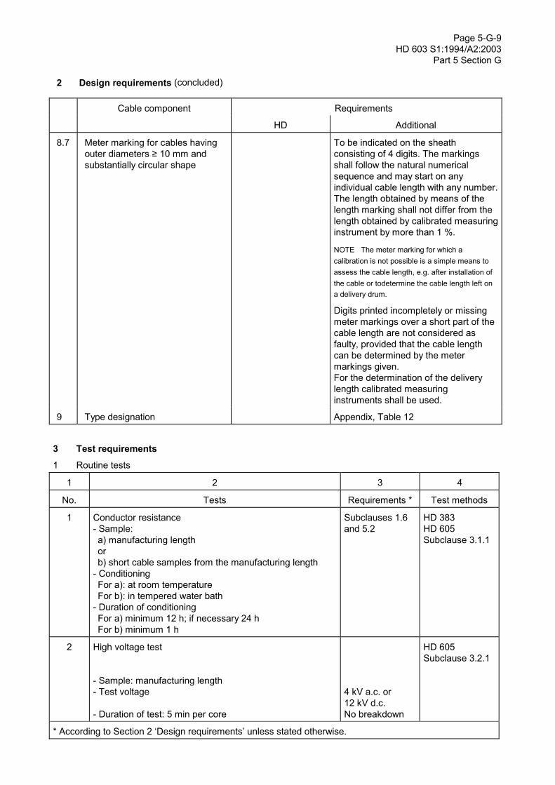
Page 5-G-9 HD 603 S1:1994/A2:2003
Part 5 Section G
2 Design requirements (concluded)
Cable component Requirements
HD Additional
8.7 Meter marking for cables having outer diameters ≥ 10 mm and substantially circular shape
To be indicated on the sheath consisting of 4 digits. The markings shall follow the natural numerical sequence and may start on any individual cable length with any number.The length obtained by means of the length marking shall not differ from the length obtained by calibrated measuring instrument by more than 1 %.
NOTE The meter marking for which a calibration is not possible is a simple means to assess the cable length, e.g. after installation of the cable or todetermine the cable length left on a delivery drum.
Digits printed incompletely or missing meter markings over a short part of the cable length are not considered as faulty, provided that the cable length can be determined by the meter markings given. For the determination of the delivery length calibrated measuring instruments shall be used.
9 Type designation Appendix, Table 12
3 Test requirements 1 Routine tests
1 2 3 4
No. Tests Requirements * Test methods
1 Conductor resistance - Sample: a) manufacturing length or b) short cable samples from the manufacturing length - Conditioning For a): at room temperature For b): in tempered water bath - Duration of conditioning For a) minimum 12 h; if necessary 24 h For b) minimum 1 h
Subclauses 1.6 and 5.2
HD 383 HD 605 Subclause 3.1.1
2 High voltage test - Sample: manufacturing length - Test voltage - Duration of test: 5 min per core
4 kV a.c. or 12 kV d.c. No breakdown
HD 605 Subclause 3.2.1
* According to Section 2 Design requirements unless stated otherwise.

Page 5-G-10 HD 603 S1:1994/A2:2003 Part 5 Section G
3 Test requirements (continued) 2 Sample tests 1)
1 2 3 4
No. Tests Requirements * Test methods
1 Construction of conductor Subclauses 1.2 to 1.5
EN 60811-1-1 Subclause 8.3 and by inspection
2 Insulation - Thickness 2) 3)
Subclause 2.2
EN 60811-1-1 Subclause 8.1
3 Inner covering - Thickness
Subclause 4 EN 60811-1-1 Subclause 8.2
4 Concentric conductor - Dimensions of copper binder tapes - Clearance between wires
Subclause 5.3 Subclause 5.4
HD 605 Subclause 2.1.4.2 HD 603-5G Section 2 (Design) item 5.4
5 Sheath - Thickness 3)
Subclause 6.3 EN 60811-1-1 Subclause 8.2
6 Hot set test on insulation HD 603-1 Table 2 compound DIX 3
EN 60811-2-1 Subclause 9
7 Shrinkage test of PE outer sheath - Sample: specimen (500 ± 5) mm in length - Conditioning: 24 h at (23 ± 10) °C - Temperature cycles laying in an oven at: (80 ± 1) °C for a min. of 5 h - Cooling to ambient temperature of (23 ± 10) °C - Number of cycles 5
Shrinkage ≤ 7 mm
HD 605 Subclause 2.4.4.1 method 1
8 Outer diameter Subclause 7 EN 60811-1-1 Subclause 8.3
9 Marking Subclause 8 Test by inspection 1) Sample tests shall be carried out on 10 % of a manufacturing lot of the same cable type, i.e. at least on one cable length.
If any sample should fail in any of the sample tests requested it is permitted to choose one or two additional sample(s) from the same cable length and to submit the additional sample(s) to the test or tests in which the original sample failed.
The samples shall be taken at least 0,5 m from the cable end(s).
For the resampling procedure, the following rules apply:
- number of samples to be taken as for the first test,
- if for the first test one sample from both cable ends has to be taken, is it deemed sufficient to resample one additional sample from the cable end the first sample of which failed. 2) Measurement at 10 % of the cores, at least at 4 cores. 3) One sample of each end of the cable in a distance of approximate 50 cm from the ends.
* According to Section 2 Design requirements unless stated otherwise.

Page 5-G-11 HD 603 S1:1994/A2:2003
Part 5 Section G
3 Test requirements (continued) 3 Type Tests (electrical characteristics) 1)
1 2 3 4
No. Tests Requirements * Test methods
1 Volume resistivity of insulation at 90 °C - time of immersion in water 2) - time of measurement: after 1 min
HD 603-1 Table 2A, DIX 3
HD 605 Subclause 3.3.1
2 High voltage test - length of sample 10 - 15 m - Test voltage (a.c.) 1,8 kV - Duration of test 4 h
No breakdown
HD 605 Single-core cables without concentric conductor: Subclause 3.2.1.1 Multi-core cables: Subclause 3.2.1.2
3 Surface resistance of sheath Ω ≥ 109 HD 605 Subclause 3.4
1) Type tests include tests classified as sample (S) or routine (R) tests. 2) 60 min for cables with cross-areas up to and including 10 mm2 or (60 + S) min for cables with cross-areas greater than 10 mm2 where S is the figure of the nominal cross section area.
* According to Section 2 Design requirements unless stated otherwise.
4 Type tests (non-electrical characteristics) 1)
1 2 3 4
No. Tests Requirements * Test methods
1 Tests on insulation
1.1 Mechanical characteristics a) Without ageing b) After ageing in air oven
HD 603-1 Table 2A - DIX 3
EN 60811-1-1 Subclause 9.1 EN 60811-1-2 Subclause 8.1
1.2 Water absorption - Duration of test 14 d - Test temperature (85 ± 3) °C
HD 603-1 Table 2A - DIX 3
EN 60811-1-3 Subclause 9.2
1) Type tests include tests classified as sample (S) or routine (R) tests.
* According to Section 2 Design requirements unless stated otherwise.

Page 5-G-12 HD 603 S1:1994/A2:2003 Part 5 Section G
3 Test requirements (continued) 4 Type tests (non-electrical characteristics, continued)
1 2 3 4
No. Tests Requirements * Test methods
2 Test on cores
2.1 Mechanical characteristics EN 60811-1-2 Subclause 8.1
2.1.1 After ageing with copper conductor followed by tensile testa) Treatment Temperature (150 ± 3) °C Duration 7 d b) Tensile strength Variation, maximum c) Elongation at break Variation, maximum
± 30 % ± 30 %
EN 60811-1-2 Amendment 1
2.1.2 After ageing with copper conductor followed by bending test (only if 2.1.1 is not practicable) a) Treatment Temperature (150 ± 3) °C Duration 10 d b) Results to be obtained
No cracks
EN 60811-1-2 Amendment 1
2.2 Shrinkage test Length of the test sample: 300 mm
HD 603-1 Table 2A - DIX 3
EN 60811-1-3 Subclause 10
3 Tests on sheath
3.1 Mechanical characteristics a) Without ageing b) After ageing in air oven
HD 603-1 Table 4A or 4B DMV 6 or DMP 2 respectively
EN 60811-1-1 Subclause 9.2 EN 60811-1-2 Subclause 8.1
3.2 Pressure test at high temperature HD 603-1 Table 4A or 4B DMV 6 or DMP 2 respectively 2)
EN 60811-3-1 Subclause 8.2
3.3 Elongation test at low temperature for cables with PVC sheath and diameter of more than 12,5 mm Temperature (-15 ± 2) °C
HD 603-1 Table 4A DMV 6 Elongation at break ≥ 20 %
EN 60811-1-4 Subclause 8.4
3.4 Loss of mass test in air oven for PVC sheath HD 603-1 Table 4A - DMV 6
EN 60811-3-2 Subclause 8.2
3.5 Heat shock test for PVC sheath HD 603-1 Table 4A - DMV 6
EN 60811-3-1 Subclause 9.2
3.6 Thermal stability test for PVC sheath Temperature (200 ± 0,5) °C
HD 603-1 Table 4A - DMV 6
EN 60811-3-2 Subclause 9
3.7 Stress-cracking resistance for PE-sheath HD 603-1 Table 4B - DMP 2
EN 60811-4-1 Clause 8 Procedure B but with a duration of 1 000 h
2) For outer diameter ≤ 12,5 mm: 4 h; > 12,5 mm: 6 h.
* According to Section 2 Design requirements unless stated otherwise.
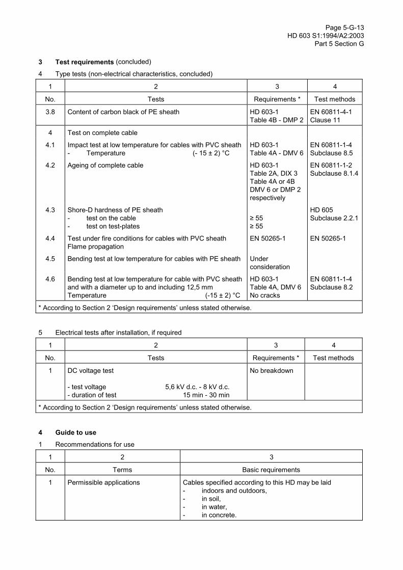
Page 5-G-13 HD 603 S1:1994/A2:2003
Part 5 Section G
3 Test requirements (concluded) 4 Type tests (non-electrical characteristics, concluded)
1 2 3 4
No. Tests Requirements * Test methods
3.8 Content of carbon black of PE sheath HD 603-1 Table 4B - DMP 2
EN 60811-4-1 Clause 11
4 Test on complete cable
4.1 Impact test at low temperature for cables with PVC sheath- Temperature (- 15 ± 2) °C
HD 603-1 Table 4A - DMV 6
EN 60811-1-4 Subclause 8.5
4.2 Ageing of complete cable HD 603-1 Table 2A, DIX 3 Table 4A or 4B DMV 6 or DMP 2 respectively
EN 60811-1-2 Subclause 8.1.4
4.3 Shore-D hardness of PE sheath - test on the cable - test on test-plates
≥ 55 ≥ 55
HD 605 Subclause 2.2.1
4.4 Test under fire conditions for cables with PVC sheath Flame propagation
EN 50265-1 EN 50265-1
4.5 Bending test at low temperature for cables with PE sheath Under consideration
4.6 Bending test at low temperature for cable with PVC sheathand with a diameter up to and including 12,5 mm Temperature (-15 ± 2) °C
HD 603-1 Table 4A, DMV 6 No cracks
EN 60811-1-4 Subclause 8.2
* According to Section 2 Design requirements unless stated otherwise.
5 Electrical tests after installation, if required
1 2 3 4
No. Tests Requirements * Test methods
1
DC voltage test - test voltage 5,6 kV d.c. - 8 kV d.c. - duration of test 15 min - 30 min
No breakdown
* According to Section 2 Design requirements unless stated otherwise.
4 Guide to use 1 Recommendations for use
1 2 3
No. Terms Basic requirements
1 Permissible applications Cables specified according to this HD may be laid - indoors and outdoors, - in soil, - in water, - in concrete.

Page 5-G-14 HD 603 S1:1994/A2:2003 Part 5 Section G
4 Guide to use (continued) 1 Recommendations for use (concluded)
1 2 3
No. Terms Basic requirements
2 Highest permissible voltage - DC systems 1,8 kV - AC systems - single-phase both conductors insulated 1,4 kV one conductor earthed 0,7 kV - three-phase cables system 1,2 kV however three-phase cables with concentric conductor and cross-sectional area from 240 mm2 upwards 3,6 kV
3 Precautions against electric shock
Cables without metallic covering are suitable for Class II equipment.
4 Concentric conductor May be used as PE-conductor, PEN conductor or as a screen.
2 Recommendations for storage and transport
1 2 3
No. Terms Basic requirements
1
1.1
1.2
1.3
Delivery Distance between the outer cable layer and the head of the flange Barrel of delivery drums Cable sealing end
- 2 x cable diameter but at least 5 cm According to Appendix, Table 13 The cable ends have to be sealed during transport, storage and laying to prevent ingress of water.
2
2.1
2.2
2.3
2.4
2.5
Transport Carriers Drum axis position Loading and unloading Rolling of cable drums Cable rings
The cable ends shall be tightened properly. Only suitable carriers shall be used. Cable drums with flange diameters exceeding 1 m have to be transported with horizontal drum axis. Only suitable carriers shall be used. Filled-up cable drums shall be rolled only on short distances over plain solid ground in the direction indicated. Short cable lengths may be coiled to rings and transported and stored horizontally.. The permissible bending radii shall not fall short of the values given in this section, Clause 3, item 4.
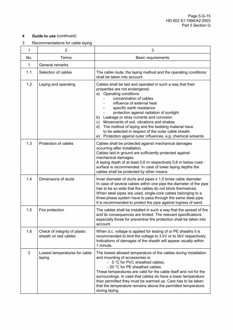
Page 5-G-15 HD 603 S1:1994/A2:2003
Part 5 Section G
4 Guide to use (continued) 3 Recommendations for cable laying
1 2 3
No. Terms Basic requirements
1 General remarks
1.1 Selection of cables The cable route, the laying method and the operating conditions shall be taken into account
1.2 Laying and operating Cables shall be laid and operated in such a way that their properties are not endangered. a) Operating conditions - concentration of cables - influence of external heat - specific earth resistance - protection against radiation of sunlight b) Leakage or stray currents and corrosion c) Movements of soil, vibrations and shakes d) The method of laying and the bedding material have to be selected in respect of the outer cable sheath. e) Protection against outer influences, e.g. chemical solvents
1.3 Protection of cables Cables shall be protected against mechanical damages occurring after installation. Cables laid in ground are sufficiently protected against mechanical damages. A laying depth of at least 0,6 m respectively 0,8 m below road-surface is recommended. In case of lower laying depths the cables shall be protected by other means.
1.4 Dimensions of ducts Inner diameter of ducts and pipes ≥ 1,5 times cable diameter. In case of several cables within one pipe the diameter of the pipe has to be so wide that the cables do not block themselves. When steel pipes are used, single-core cables belonging to a three-phase system have to pass through the same steel pipe. It is recommended to protect the pipe against ingress of sand.
1.5 Fire protection The cables shall be installed in such a way that the spread of fire and its consequences are limited. The relevant specifications especially those for preventive fire protection shall be taken into account.
1.6 Check of integrity of plastic sheath on laid cables
When d.c. voltage is applied for testing of or PE sheaths it is recommended to limit the voltage to 3 kV or to 5kV respectively. Indications of damages of the sheath will appear usually within 1 minute.
2 Lowest temperatures for cable laying
The lowest allowed temperature of the cables during installation and mounting of accessories is: - 5 °C for PVC sheathed cables, - 20 °C for PE sheathed cables. These temperatures are valid for the cable itself and not for the surroundings. In case that cables do have a lower temperature than permitted they must be warmed up. Care has to be taken that the temperature remains above the permitted temperature during laying.

Page 5-G-16 HD 603 S1:1994/A2:2003 Part 5 Section G
4 Guide to use (continued) 3 Recommendations for cable laying (concluded)
1 2 3
No. Terms Basic requirements
3 Pulling loads
3.1 Pulling force a) Pulling head b) Pulling grip
Maximum pulling force P = S σ where cross-sectional area of conductor S in mm2 and permissible tensile stress σ = 50 N/mm2 for cables with copper conductors σ = 30 N/mm2 for cables with aluminium conductors With this pulling force it is guaranteed that the permitted elongation of 0,2 % for the conductor will not be exceeded. The maximum permissible pulling force (P in N) is calculated from the total of the nominal cross-sectional area. The nominal cross-sectional area of the screens and of the concentric conductors shall not be considered in this calculation. For the pulling of cables having no metallic sheath and no armouring the pulling force can be transmitted by a pulling grip via a frictional connection between the pulling grip and the conductor of the cable. Therefore the same pulling loads apply as for the pulling head.
3.2 Types of laying Cables may be dug in also by means of a plough or they may be laid by a flushing-in method.
3.3 Preparation of cable route It is assumed that the cable route is well designed for the laying procedure with well-established curves and a sufficient number of cable rollers. Special attention shall be paid to the required minimum bending radii (see Clause 4). The pulling force shall be permanently supervised during the pull-in procedure.
4 Bending radii a) Permissible bending radius b) Reduction of bending radius
During installation - single-core cables: 15 times the cable diameter - multi-core cables: 12 times the cable diameter By 50 % provided that - single-time bending, - the work is made by skilled workers, - the cable is heated up to 30 °C, - the cable is bent by means of a template.
5 Cable fixing Single-core cables may be laid alone or systemwise in bundles. A system of bundled cables may be treated as a multi-core cable. In case of separate laying of single-core cables, cleats made of plastics or cleats consisting of non-magnetic metals have to be used. Steel cleats may be used if the magnetic circuit is not closed. Cables and bundles of cables are to be tightened in such a way that damages in form of indentation marks by pressure caused by heat expansion are avoided.
5.1 Horizontal distance between cleats
20 times the cable diameter. This distance is also valid between points of support in case of laying on cable racks or inside cable trays. In any case a distance of 80 cm should not be exceeded.
5.2 Vertical distance between cleats
For vertical cable laying on walls higher distance between the cleats is permitted. The distance of 1,5 m, however, should not be exceeded.

Page 5-G-17 HD 603 S1:1994/A2:2003
Part 5 Section G
4 Guide to use (concluded) 4 Recommendations for fault detection
1 2 3
No. Tests Basic requirements
1 Fault detection on a cable - By d.c. voltage up to the relevant test voltage according to HD 603 -5G, Section 3, Subclause 5, so far permanently connected equipment permits this - By impulse voltage up to d.c. test voltage (HD 603-5G, Section 3, Subclause 5)
2 Fault detection on the sheath When d.c. voltage is applied for fault location on PVC sheaths it is recommended to limit the voltage to 3 kV. Appropriate test procedures have to be chosen to prevent secondary damages of the cable, e.g. by the energy content of impulse waves.
5 Current-carrying capacity (recommended values)
1 2 3 4
N° Terms Requirements Quantity
1 General This section applies to the current-carrying capacity under both standard and deviating provisions provided that the cables are in three-phase operation with three conductors loaded or one single-core cable in d.c.-operation
2 2.1 2.2 2.3 2.4
Temperatures Bonding Frequency Operating conditions
Basic provisions Maximum permissible operating temperature Maximum short-circuit temperature Concentric conductors bonded at both ends Power frequency The tabulated rated current-carrying capacities are based on standard provisions such as: - operating mode - laying conditions - environmental conditions For deviating operating conditions the current-carrying capacities in the tables are to be multiplied by appropriate conversion factors 1) which shall be based on the same calculation method and operating conditions as used for the current-carrying capacity given in this clause.
90 °C 250 °C 50 Hz See Appendix, Tables 14, 15
3 3.1 3.1.1 3.1.2 3.1.3
Operating mode Laying conditions Environmental conditions
Cables in earth Rated current-carrying capacity Ir under standard provisions Cyclic load load factor (Definition of load factor, see Appendix, Table 16) Laying depth One multicore cable laid single Three single-core cables in close trefoil formation laid throughout the cable length with one system only. Ambient temperature, soil Soil thermal resistivity, dried-out soil Soil thermal resistivity, moist soil
See Appendix, Table 14 0,7 0,7 m 20 °C 2,5 K.m/W 1,0 K.m/W
1) To be agreed between purchaser and producer.

Page 5-G-18 HD 603 S1:1994/A2:2003 Part 5 Section G
5 Current-carrying capacity (concluded)
1 2 3 4
N° Terms Requirements Quantity
3.2 3.2.1 3.2.2 3.2.3
Operating mode Laying conditions Environmental conditions
Current-carrying capacity under deviating provisions 1) Load factor ⇒ factors f1 x f2 Laying depth Grouping of cables ⇒ factors f1 x f2 Ambient temperature ⇒ factors f1 x f2 Soil thermal resistivity, moist soil ⇒ factors f1 x f2
0,5... 1 0,7... 1,2 m 5 °C... 40 °C 0,7.. 2,5 K.m/W
4 4.1 4.1.1 4.1.2 4.1.3 4.2 4.2.1 4.2.2 4.2.3
Operating mode Laying conditions Environmental conditions Operating mode Laying conditions Environmental conditions
Cables in air - Rated current-carrying capacity Ir under standard provisions Continuous operation, load factor - Free in air - One multicore cable laid singly. Three single-core cables laid throughout the cable length in close trefoil formation with one system only. protection against direct thermal radiation due to sun etc. - Ambient temperature, air Current-carrying capacity under deviating provisions 1) -- - Grouping of cables on trays and ladders - Ambient temperature, air
See Appendix, Table 15 1,0 30 °C -- 10 °C... 50 °C
5 5.1 5.2
Rated short-circuit current (thermal) Permissible short-circuit current (thermal)
Short-circuit During a short-circuit cables are loaded thermally and mechanically as well. Therefore the nominal cross-sectional area Sn, the cable and if necessary the fixing of cables are to be selected carefully such that the cables are not overloaded. The following provisions are valid for a short-circuit duration up to 5 s. The rated short-circuit current for a short-circuit duration of 1 s is calculated by multiplying the rated short-time current density with the nominal cross-sectional area of the conductor. For short-circuit durations deviating from 1 s the permissible short-circuit current is to be calculated by dividing the rated short-circuit current with the square root of the short-circuit duration (in s).
See Appendix, Table 17
5.3 Permissible short-circuit current (dynamic)
For multicore cables special measures are not required up to 40 kA (peak value). Single-core cables shall be safety fixed to withstand the effects of peak short-circuit currents.
1) To be agreed between purchaser and producer.

Page 5-G-19 HD 603 S1:1994/A2:2003
Part 5 Section G
6 Appendix (tables)
Table 1 - Solid sector-shaped aluminium conductors (class 1); α = 90°, α = 120°
1 2 3 4 5 6 7 8 9
Nominal h d b r1 r2 a
cross-sectional
area
approx. value
nominal value
tolerance nominal value
tolerance approx. value
approx. value
approx. value
mm2 mm mm mm mm mm mm mm mm
α = 120°
50 70 95 120 150 185 240
6,5 8,1 9,3 10,5 11,5 12,8 14,5
6,2 7,7 8,9 10,0 11,0 12,3 14,0
± 0,5 ± 0,5 ± 0,5 ± 0,6 ± 0,6 ± 0,6 ± 0,6
9,8 10,9 13,5 15,5 17,5 20,1 23,4
± 0,6 ± 0,6 ± 0,6 ± 0,6 ± 0,6 ± 0,7 ± 0,7
8,1 9,8 11,2 12,3 13,6 15,1 17,0
1,8 2,8 2,8 3,0 3,0 3,0 3,0
2,6 3,3 3,8 4,3 4,7 5,3 6,0
α = 90°
50 70 95 120 150 185 240
7,6 9,5 10,9 12,3 13,4 15,0 17,0
6,9 8,3 9,7 11,1 12,2 13,8 15,8
± 0,5 ± 0,5 ± 0,5 ± 0,6 ± 0,6 ± 0,6 ± 0,6
9,1 10,4 12,7 14,5 16,2 18,7 21,9
± 0,5 ± 0,6 ± 0,6 ± 0,6 ± 0,6 ± 0,6 ± 0,6
9,6 11,5 13,3 14,5 15,9 17,8 20,1
1,8 2,8 2,8 3,0 3,0 3,0 3,0
2,3 3,1 3,4 3,8 4,1 4,4 4,9
b
hα
r2
r2
r1d
a

Page 5-G-20 HD 603 S1:1994/A2:2003 Part 5 Section G
6 Appendix (tables) (continued)
Table 2 - Stranded sector-shaped aluminium or copper conductors (class 2); α = 90°, α = 120°
1 2 3 4 5 6 7 8
Nominal h d b r1 r2 a
cross-sectional area
approx. value
nominal value
tolerance nominal value
approx. value
approx. value
approx. value
mm2 mm mm mm mm mm mm mm
α = 120°
35 1) 50 70 95 120 150 185 240
300 1)
6,1 7,1 8,6 10,0 11,2 12,6 14,0 16,0 17,8
5,9 6,8 8,2 9,6 10,8 12,2 13,6 15,6 17,4
± 0,7 ± 0,7 ± 0,7 ± 0,7 ± 0,8 ± 0,8 ± 0,8 ± 0,8 ± 0,8
9,5 10,9 13,1 15,6 17,7 20,3 23,1 26,7 29,5
7,5 8,7 10,3 12,0 13,0 14,6 16,0 18,2 20,5
1,5 1,8 2,3 2,4 2,4 2,5 2,5 2,6 2,9
2,5 2,9 3,5 4,1 4,7 5,3 5,9 6,8 7,6
α = 90°
35 1) 50 70 95 120 150 185 240
300 1)
7,2 8,3 10,0 11,7 13,2 14,6 16,2 18,6 20,6
6,5 7,6 9,0 10,7 12,1 13,5 15,1 17,4 19,4
± 0,7 ± 0,7 ± 0,7 ± 0,8 ± 0,8 ± 0,8 ± 0,8 ± 0,8 ± 0,8
8,9 10,4 12,1 14,7 16,4 18,4 20,8 24,3 27,3
9,0 10,3 12,3 14,1 15,5 17,2 19,0 21,6 24,0
1,6 1,7 2,3 2,3 2,7 2,7 2,7 2,8 2,8
2,1 2,4 3,0 3,4 3,9 4,3 4,7 5,3 5,8
1) Copper conductors only.
h
α
r2
r2
r1
d
a
b

Page 5-G-21 HD 603 S1:1994/A2:2003
Part 5 Section G
6 Appendix (tables) (continued)
Table 3 - Stranded sector-shaped aluminium or copper conductors (class 2); α = 60°, α = 100°
1 2 3 4 5 6 7 8
Nominal h d b r1 r2 a
cross-sectional area
approx. value
nominal value
tolerance nominal value
approx. value
approx. value
approx. value
mm2 mm mm mm mm mm mm mm
α = 100°
50 70 95 120 150 185 240
300 1)
8,1 9,5 11,2 12,5 14,0 15,5 17,8 20,0
7,6 8,8 10,5 11,6 13,2 14,6 16,9 19,2
± 0,7 ± 0,7 ± 0,8 ± 0,8 ± 0,8 ± 0,8 ± 0,8 ± 0,8
11,0 12,5 15,3 17,0 19,4 22,0 25,5 29,1
9,9 11,3 13,3 14,6 16,3 18,1 20,7 23,1
1,7 2,3 2,3 2,7 2,7 2,7 2,8 2,8
2,7 3,2 3,7 4,1 4,6 5,0 5,8 6,5
α = 60°
35 1) 50 70 95 120 150 185
9,2 10,9 13,2 15,2 17,0 19,0 20,5
7,6 9,2 10,9 12,9 14,3 16,3 17,8
± 0,7 ± 0,7 ± 0,8 ± 0,8 ± 0,8 ± 0,8 ± 0,8
7,9 9,6 11,4 13,5 14,9 16,9 18,7
11,3 13,3 16,3 18,1 20,7 23,1 26,5
1,6 1,7 2,3 2,3 2,7 2,7 2,7
1,9 2,1 2,7 2,9 3,4 3,6 3,6
1) Copper conductors only.
h
α
r2
r2
r1
d
a
b

Page 5-G-22 HD 603 S1:1994/A2:2003 Part 5 Section G
6 Appendix (tables) (continued)
Table 4 - Permissible conductor types
1 2
Type of conductor Range of cross-sectional area
Copper mm2
Aluminium mm2
Circular, solid Circular, stranded
Shaped, solid Shaped, stranded
1,5 to 16 1,5 to 500 1)
-- 35 to 300
25 to 50 50 to 630 1) 50 to 240 50 to 240
1) For single-core cables up to and including 1 000 mm2.
Table 5 - Allocation of conductors with a reduced cross-sectional area
Nominal cross-sectional area of the phase conductors
mm2
Nominal cross-sectional area of the conductor with a reduced cross-sectional area
mm2
25 35 50 70 95 120 150 185 240 300 400 500
16 16 25 35 50 70 70 95 120 150 185 240

Page 5-G-23 HD 603 S1:1994/A2:2003
Part 5 Section G
6 Appendix (tables) (continued)
Table 6 - Core identification in multi-core cables by colours 3) 4)
1 2 3 4
Number of cores With green-yellow marked core
Without green-yellow marked core
With concentric conductor
2 green-yellow black 1)
acc. to HD 308 acc. to HD 308
3 acc. to HD 308 acc. to HD 308 acc. to HD 308
4 acc. to HD 308 2) acc. to HD 308 2) acc. to HD 308
5 2) acc. to HD 308 2) acc. to HD 308 2) 1) This two-core design is only permissible for conductor cross-sectional area equal or greater than 10 mm2 copper or 16 mm2 aluminium. 2) Where cables have a core with a reduced conductor cross section, this core shall be marked green-yellow in designs according to column 2 and blue in designs according to column 3. 3) If the core is marked on the surface only, the insulation under the surface shall have no colour additives, except in the case of a two-coloured identification. The specified colours shall correspond to HD 402. Precise compliance of the colours can be impeded by various influences (for example the type of material, running colour of material, texture of the surface, manufacturing methods, interference by adjacent colours, etc.). Therefore deviations from the specified colour are permissible, as long as the colours cannot be confused with another colour in daylight or artificial lighting. 4) The sequence of colours as given in the table shall be observed.
Table 7 - Thickness of the extruded inner covering
1 2 3
Fictitious diameter over the laid-up cores
mm
Thickness of the extruded inner covering (approx. value)
mm
Minimum thickness
mm
up to 25 over 25 to 35 over 35 to 45 over 45 to 60 over 60 to 80
over 80
1,0 1,2 1,4 1,6 1,8 2,0
0,5 0,6 0,7 0,8 0,9 1,0
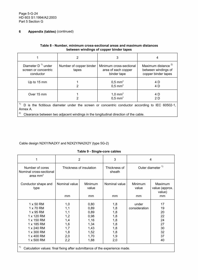
Page 5-G-24 HD 603 S1:1994/A2:2003 Part 5 Section G
6 Appendix (tables) (continued)
Table 8 - Number, minimum cross-sectional areas and maximum distances between windings of copper binder tapes
1 2 3 4
Diameter D 1) under screen or concentric
conductor
Number of copper binder tapes
Minimum cross-sectional area of each copper
binder tape
Maximum distance 2) between windings of copper binder tapes
Up to 15 mm 1 2
0,5 mm2 0,5 mm2
4 D 4 D
Over 15 mm 1 2
1,0 mm2 0,5 mm2
4 D 2 D
1) D is the fictitious diameter under the screen or concentric conductor according to IEC 60502-1, Annex A. 2) Clearance between two adjacent windings in the longitudinal direction of the cable.
Cable design N2XY/NA2XY and N2X2Y/NA2X2Y (type 5G-2)
Table 9 - Single-core cables
1 2 3 4
Number of cores Nominal cross-sectional
area mm2
Thickness of insulation Thickness of sheath
Outer diameter 1)
Conductor shape and type
Nominal value
mm
Minimum value
mm
Nominal value
mm
Minimum value
mm
Maximum value (approx.
value) mm
1 x 50 RM 1 x 70 RM 1 x 95 RM 1 x 120 RM 1 x 150 RM 1 x 185 RM 1 x 240 RM 1 x 300 RM 1 x 400 RM 1 x 500 RM
1,0 1,1 1,1 1,2 1,4 1,6 1,7 1,8 2,0 2,2
0,80 0,89 0,89 0,98 1,16 1,34 1,43 1,52 1,70 1,88
1,8 1,8 1,8 1,8 1,8 1,8 1,8 1,8 1,9 2,0
under consideration
17 19 20 22 24 27 30 32 37 40
1) Calculation values: final fixing after submittance of the experience made.

Page 5-G-25 HD 603 S1:1994/A2:2003
Part 5 Section G
6 Appendix (tables) (continued)
Cable design N2XY and N2X2Y (type 5G-2)
Table 10 - Four-core cables with copper conductors
1 2 3 4
Number of cores Nominal cross-sectional
area mm2
Thickness of insulation Thickness of sheath
Outer diameter 1)
Conductor shape and type
Nominal value
mm
Minimum value
mm
Nominal value
mm
Minimum value
mm
Maximum value (approx.
value) mm
4 x 16 RE 4 x 25 RM 4 X 35 RM
4 x 35 SM 4 x 50 SM 4 x 70 SM
4 x 95 SM 4 x 120 SM 4 x 150 SM 4 x 185 SM
0,7 0,9 0,9
0,9 1,0 1,1
1,1 1,2 1,4 1,6
0,53 0,71 0,71
0,71 0,80 0,89
0,89 0,98 1,16 1,34
1,8 1,8 1,8
1,8 1,9 2,0
2,1 2,3 2,4 2,6
under consideration
24 31 34
32 35 40
44 48 53 58
1) Calculation values: final fixing after submittance of the experience made.

Page 5-G-26 HD 603 S1:1994/A2:2003 Part 5 Section G
6 Appendix (tables) (continued)
Cable design NA2XY and NA2X2Y (type 5G-2)
Table 11 - Four-core cables with aluminium conductors
1 2 3 4
Number of cores Nominal cross-sectional
area mm2
Thickness of insulation Thickness of sheath
Outer diameter 1)
Conductor shape and type
Nominal value
mm
Minimum value
mm
Nominal value
mm
Minimum value
mm
Maximum value (approx.
value) mm
4 x 25 RE 4 x 35 RE 4 x 50 RE
4 x 50 SE 4 x 70 SE 4 x 95 SE 4 x 120 SE 4 x 150 SE
4 x 185 SE 4 x 185 SM 4 x 240 SE 4 x 240 SM
0,9 0,9 1,0
1,0 1,1 1,1 1,2 1,4
1,6 1,6 1,7 1,7
0,71 0,71 0,80
0,80 0,89 0,89 0,98 1,16
1,34 1,34 1,43 1,43
1,8 1,8 1,9
1,9 2,0 2,1 2,3 2,4
2,6 2,6 2,8 2,8
under consideration
28 30 33
33 38 41 45 49
54 58 59 64
1) Calculation values: final fixing after submittance of the experience made.
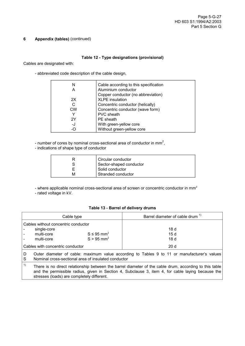
Page 5-G-27 HD 603 S1:1994/A2:2003
Part 5 Section G
6 Appendix (tables) (continued)
Table 12 - Type designations (provisional) Cables are designated with:
- abbreviated code description of the cable design,
N A
2X C
CW Y 2Y -J -O
Cable according to this specification Aluminium conductor Copper conductor (no abbreviation) XLPE insulation Concentric conductor (helically) Concentric conductor (wave form) PVC sheath PE sheath With green-yellow core Without green-yellow core
- number of cores by nominal cross-sectional area of conductor in mm2, - indications of shape type of conductor
R S E M
Circular conductor Sector-shaped conductor Solid conductor Stranded conductor
- where applicable nominal cross-sectional area of screen or concentric conductor in mm2 - rated voltage in kV.
Table 13 - Barrel of delivery drums
Cable type Barrel diameter of cable drum 1)
Cables without concentric conductor - single-core - multi-core S ≤ 95 mm2 - multi-core S > 95 mm2
Cables with concentric conductor
18 d 15 d 18 d
20 d
D S
Outer diameter of cable: maximum value according to Tables 9 to 11 or manufacturers valuesNominal cross-sectional area of insulated conductor
1) There is no direct relationship between the barrel diameter of the cable drum, according to this table and the permissible radius, given in Section 4, Subclause 3, item 4, for cable laying because the stresses (loads) are completely different.
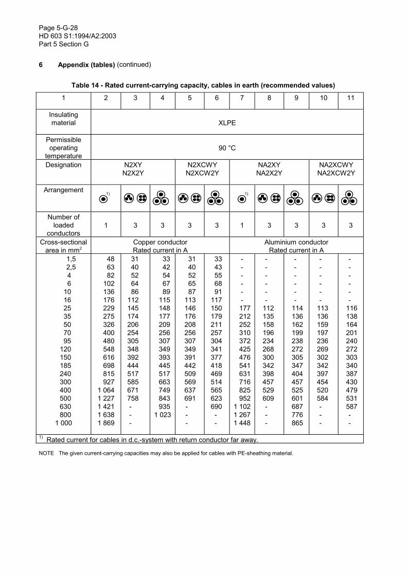
Page 5-G-28 HD 603 S1:1994/A2:2003 Part 5 Section G
6 Appendix (tables) (continued)
Table 14 - Rated current-carrying capacity, cables in earth (recommended values)
1 2 3 4 5 6 7 8 9 10 11
Insulating material
XLPE
Permissible operating
temperature
90 °C
Designation N2XY N2X2Y
N2XCWY N2XCW2Y
NA2XY NA2X2Y
NA2XCWY NA2XCW2Y
Arrangement 1)
1)
Number of loaded
conductors
1
3
3
3
3
1
3
3
3
3
Cross-sectional area in mm2
Copper conductor Rated current in A
Aluminium conductor Rated current in A
1,5 2,5
4 6 10 16 25 35 50 70 95 120 150 185 240 300 400 500 630 800 1 000
48 63 82 102 136 176 229 275 326 400 480 548 616 698 815 927 1 064 1 227 1 421 1 638 1 869
31 40 52 64 86 112 145 174 206 254 305 348 392 444 517 585 671 758 - - -
33 42 54 67 89 115 148 177 209 256 307 349 393 445 517 663 749 843 9351 023
31 40 52 65 87 113 146 176 208 256 307 349 391 442 509 569 637 691 - - -
33 43 55 68 91 117 150 179 211 257 304 341 377 418 469 514 565 623 690 - -
- - - - - -
177 212 252 310 372 425 476 541 631 716 825 9521 1021 2671 448
- - - - - - 112 135 158 196 234 268 300 342 398 457 529 609 - - -
- - - - - - 114 136 162 199 238 272 305 347 404 457 525 601 687 776 865
- - - - - - 113 136 159 197 236 269 302 342 397 454 520 584 - - -
- - - - - - 116 138 164 201 240 272 303 340 387 430 479 531 587 - -
1) Rated current for cables in d.c.-system with return conductor far away.
NOTE The given current-carrying capacities may also be applied for cables with PE-sheathing material.
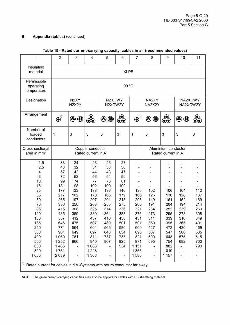
Page 5-G-29 HD 603 S1:1994/A2:2003
Part 5 Section G
6 Appendix (tables) (continued)
Table 15 - Rated current-carrying capacity, cables in air (recommended values)
1 2 3 4 5 6 7 8 9 10 11
Insulating material
XLPE
Permissible operating
temperature
90 °C
Designation N2XY N2X2Y
N2XCWY N2XCW2Y
NA2XY NA2X2Y
NA2XCWY NA2XCW2Y
Arrangement 1)
1)
Number of loaded
conductors
1
3
3
3
3
1
3
3
3
3
Cross-sectional area in mm2
Copper conductor Rated current in A
Aluminium conductor Rated current in A
1,5 2,5
4 6 10 16 25 35 50 70 95 120 150 185 240 300 400 500 630 800 1 000
33 43 57 72 99 131 177 217 265 336 415 485 557 646 774 901 1 060 1 252 1 486 1 751 2 039
24 32 42 53 74 98 133 162 197 250 308 359 412 475 564 649 761 866 - - -
26 34 44 56 77 102 138 170 207 263 325 380 437 507 604 697 811 9401 0831 2281 368
25 33 43 54 75 100 136 165 201 255 314 364 416 480 565 643 737 807 - - -
27 36 47 59 81 109 146 179 218 275 336 388 438 501 580 654 733 825 934 - -
- - - - - -
136 166 205 260 321 376 431 501 600 696 821 9711 1511 3551 580
- - - - - - 102 126 149 191 234 273 311 360 427 507 600 695 - - -
- - - - - -
106 130 161 204 252 295 339 395 472 547 643 754 882 1 019 1 157
- - - - - - 104 128 152 194 239 278 316 365 430 506 575 682 - - -
- - - - - - 112 137 169 214 263 308 349 401 469 535 615 700 790 - -
1) Rated current for cables in d.c.-Systems with return conductor far away.
NOTE The given current-carrying capacities may also be applied for cables with PE-sheathing material.
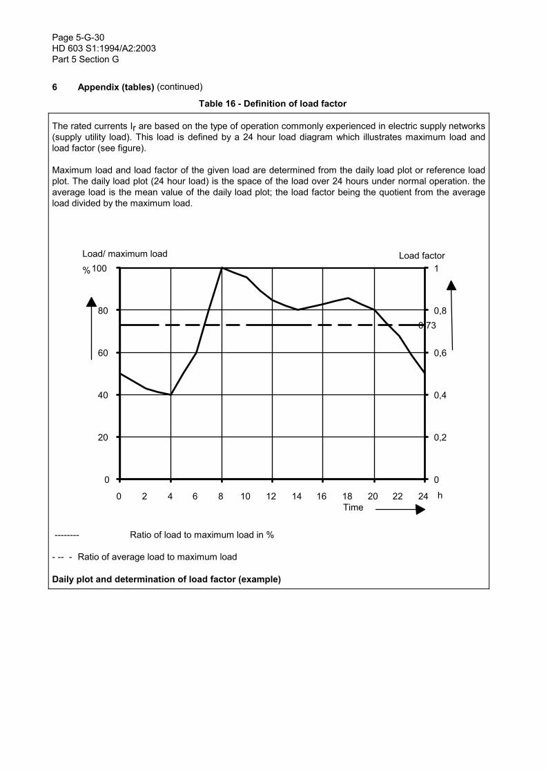
Page 5-G-30 HD 603 S1:1994/A2:2003 Part 5 Section G
6 Appendix (tables) (continued)
Table 16 - Definition of load factor
The rated currents Ir are based on the type of operation commonly experienced in electric supply networks (supply utility load). This load is defined by a 24 hour load diagram which illustrates maximum load and load factor (see figure).
Maximum load and load factor of the given load are determined from the daily load plot or reference load plot. The daily load plot (24 hour load) is the space of the load over 24 hours under normal operation. the average load is the mean value of the daily load plot; the load factor being the quotient from the average load divided by the maximum load.
0
20
40
60
80
100
0 2 4 6 8 10 12 14 16 18 20 22 24
0
0,2
0,4
0,6
0,8
1
0,73
Load/ maximum load
%Load factor
Timeh
-------- Ratio of load to maximum load in %
- -- - Ratio of average load to maximum load
Daily plot and determination of load factor (example)

Page 5-G-31 HD 603 S1:1994/A2:2003
Part 5 Section G
6 Appendix (tables) (concluded)
Table 17 - Permissible short-circuit temperatures and rated short-time current densities
1 2 3 4 5 6 7 8 9 10
Cables with Permissible short-circuit temperature
in °C
Conductor temperature at the beginning of short-circuit in °C
90 80 70 60 50 40 30 20
Rated short-time current density in A/mm2 for a rated short-circuit duration of 1 s
Copper conductors 250 143 149 154 159 165 170 176 181
Aluminium conductors
250 94 98 102 105 109 113 116 120

Page 5-G-32 HD 603 S1:1994/A2:2003 Part 5 Section G
BLANK PAGE
Page 5-I-0 HD 603 S1:1994/A2:2003
Part 5 Section I
SECTION 5-I - CABLES WITHOUT CONCENTRIC CONDUCTOR (TYPE 5I)
Replace Section 5-I
by the following A2 referred new Section 5-I:

Page 5-I-1 HD 603 S1:1994/A2:2003
Part 5 Section I
SECTION 5-I - CABLES WITHOUT CONCENTRIC CONDUCTOR (TYPE 5I)

Page 5-I-2 HD 603 S1:1994/A2:2003 Part 5 Section I
CONTENTS
1 General ------------------------------------------------------------------------------------------------------------------- 3
2 Design requirements---------------------------------------------------------------------------------------------------------- 4
1 Conductor ------------------------------------------------------------------------------------------------------------- 4 1.1 Material 1.2 Main conductors 1.3 Mechanical properties of aluminium conductors 1.4 Auxiliary conductors 1.5 Conductor resistance 1.6 Permissible conductor types
2 Insulation -------------------------------------------------------------------------------------------------------------- 4 2.1 Material 2.2 Insulation thickness 2.3 Core identification
3 Assembly of cores and fillers ------------------------------------------------------------------------------------- 5 3.1 Assembly of cores 3.2 Fillers
4 Inner covering -------------------------------------------------------------------------------------------------------- 5 4.1 Thickness
5 Sheath ----------------------------------------------------------------------------------------------------------------- 5 5.1 Material 5.2 Thickness 5.3 Colour
6 Marking ---------------------------------------------------------------------------------------------------------------- 5 6.1 Indication of origin 6.2 Year of manufacture 6.3 Code designations 6.4 Continuity of marks 6.5 Durability 6.6 Legibility 6.7 Meter marking
7 Code designation---------------------------------------------------------------------------------------------------- 6
3 Test requirements ------------------------------------------------------------------------------------------------------------- 6 1 Routine tests ------------------------------------------------------------------------------------------------- 6 2 Sample tests-------------------------------------------------------------------------------------------------- 7 3 Type tests, electrical---------------------------------------------------------------------------------------- 9 4 Type tests, non-electrical---------------------------------------------------------------------------------- 9
4 Appendix (tables and Guide to use)--------------------------------------------------------------------------------------12

Page 5-I-3 HD 603 S1:1994/A2:2003
Part 5 Section I
REFERENCES References are made in Section 5-I of HD 603, to other parts of this HD and to other Harmonization Documents and International Standards as follows:
HD 383 Conductors of insulated cables First supplement: Guide to the dimensional limits of circular conductors (endorsing IEC 60228 and 60228A)
HD 605 Electric cables Additional test methods
EN 50265 (series) Common test methods for cables under fire conditions Test for resistance to vertical flame propagation for a single insulated conductor or cable
EN 60811 (series) Insulating and sheathing materials of electric cables Common test methods
In all cases reference to another HD or International Standard implies the latest edition of that document.
1 General
This standard specifies the construction, dimensions and test requirements of XLPE-insulated power cables without concentric conductor and with PVC sheath (type 5I) for rated voltage (U) of 1 kV for fixed installations
The cables may be provided with auxiliary cores.
(a) Insulating materials
The insulation covered by this standard shall consist of cross-linked polyethylene and correspond to Table 2A, type DIX3 of HD 603-1.
(b) Rated voltage
0,6/1 kV
Definitions: see HD 603-1, Subclause 2.3
(c) Highest rated temperatures for the insulating compound
Normal operation 90 °C
(d) Sheathing material
Shall be suitable for the maximum rated conductor temperature. It shall consist of PVC and correspond to Table 4A, type DMV15 of HD 603-1.
(e) Test requirements
Type test (symbol T): validity of a type test is 5 years.

Page 5-I-4 HD 603 S1:1994/A2:2003 Part 5 Section I
2 Design requirements
No. Cable component Requirements
HD Additional
1 Conductor HD 603-1 Subclause 5.1
1.1 Material HD 603-1 Subclause 5.1.1
1.2 Main conductors HD 383
1.2.1 Composition and material a) Circular solid aluminium or copper b) Circular non- compacted stranded copper
Table 1 Table 2
The surface of aluminium conductors shall be smooth
1.3 Mechanical properties of aluminium conductors (after cabling) a) Tensile strength b) Elongation at break
≥ 60 and ≤ 120 N/mm2 ≥ 20 %
1.4 Auxiliary conductors HD 383
1.4.1 Composition and material Circular solid copper
Table 1
1.5 Conductor resistance HD 383
1.6 Permissible conductor types
Appendix, Table 1
2 Insulation HD 603-1 Subclause 5.2
2.1 Material HD 603-1 Table 2A type DIX3
2.2 Insulation thickness
2.2.1 Main cores
a) Specified values b) Mean value c) Minimum value
HD 603-1, Table 5
≥ specified value ≥ specified value - (0,1 mm + 10 % of specified value)
2.2.2 Auxiliary cores a) Specified value b) Minimum value
Appendix, Table 1 ≥ specified value - (0,1 mm + 10 % of specified value)
2.3 Core identification
2.3.1 Main cores At the outer end of the cable on the drum, core colours shall be in a clockwise direction as follows: red, yellow, blue, yellow/blue.

Page 5-I-5 HD 603 S1:1994/A2:2003
Part 5 Section I
2 Design requirements (continued)
No. Cable component Requirements
HD Additional
2.3.2 Auxiliary cores Colours shall be as follows: a) Four auxiliary cores of equal cross- sectional area: same as main cores b) Two auxiliary cores: red, blue c) Four auxiliary cores, two groups of different cross-sectional area: - larger cross-sectional area: red, blue - smaller cross-sectional area: yellow, yellow/blue
Each auxiliary core at the outer end of the cable on the cable drum, is situated on the right hand side of the main core with the same colour.
2.3.3 Colour combination yellow/blue
The colour stripes shall be applied to the corein longitudinal direction. The distribution of the colours shall be such that each colour covers at least 20 % of the surface of the core. On any 50 mm length of the outer side of the twisted cores both colours shall be discernible.
3 Assembly of cores HD 603-1 Subclause 5.3
Cores shall be laid up. Auxiliary cores shall be laid in the interstices of the main cores.
4 Filler
4.1 Centre filler HD 603-1 Subclause 5.4
A centre filler shall of non hygroscopic material be applied
4.2 Inner covering HD 603-1 Subclause 5.5
The inner covering shall be extruded and shall fill the interstices
4.2.1 Thickness a) Specified value b) Mean value c) Minimum value
a) Appendix, Table 1 b) ≥ specified value c) ≥ 2,0 mm
5 Sheath HD 603-1 Subclause 5.8
5.1 Material HD 603-1 Table 4A type DMV15
5.2 Thickness a) Specified value b) Mean value c) Minimum value
Appendix, Table 1 ≥ specified value ≥ specified value - (0,1 mm + 15 % of specified value)
5.3 Colour grey
6 Marking HD 603-1 Clause 3
Marking shall be applied by embossing or printing.

Page 5-I-6 HD 603 S1:1994/A2:2003 Part 5 Section I
2 Design requirements (concluded)
No. Cable component Requirements
HD Additional
6.1 Indication of origin on the sheath
Manufacturers name or trademark
6.2 Year of manufacture To be indicated on the sheath
6.3 Code designation To be indicated on the sheath
6.4 Continuity of marks (except meter marking)
Distance between the end of one set of marks and the beginning of the next ≤ 0,5 m
65 Durability HD 603-1 Subclause 3.3
6.6 Legibility HD 603-1 Subclause 3.4
6.7 Meter marking - Either by a tape in the cable - Or by embossing or printing on the sheath
7 Code designation Examples *:
a) for cables without auxiliary cores YMvK 0,6/1 4x10rm NEN 3616 b) for cables with auxiliary cores YMvkh 0,6/1 kV 4x25rs + 4x2,5 NEN 3616
* rm = circular solid conductor - rs = circular stranded conductor.
3 Test requirements 1 Routine tests
1 2 3 4
No. Tests Requirements * Test methods
1 Conductor resistance Ref.No.1.5 HD 605, Subclause 3.1.1
2 High voltage test on complete cable ** - Test voltage - Duration of test - Test result
4 kV a.c. 5 min per core No breakdown
Four core cable without auxiliary cores: a) red and blue yellow, yellow/blue and earth b) yellow and yellow/blue red, blue and earth c) two adjacent cores remaining cores and earth Four core cable with auxiliary cores: a) red and blue yellow, yellow/blue, all auxiliary cores and earth b) yellow and yellow/blue red, blue, all auxiliary cores and earth c) two adjacent cores and all auxiliary cores remaining cores and earth
3 Constructional characteristics
Section 2 and HD 603-1, Clause 5
3.1 General construction of cable
Visual inspection
3.2 Core identification Ref. no.2.3
3.3 Marking HD 603, Clause 3 & Ref. no. 6
* According to Section 2 Design requirements unless stated otherwise. ** Concentric conductor or armour, if present, shall be connected to earth.

Page 5-I-7 HD 603 S1:1994/A2:2003
Part 5 Section I
3 Test requirements (continued) 2 Sample tests
Frequency and sampling category: see ref. no. 5.1.1 of the sample tests see ref. no. 5.1.2 of the sample tests Repetition of sample tests in case of non compliance: see ref. no. 5.2
1 2 3 4
No. Tests Requirements * Test methods
1 Aluminium conductors
1.1 - Condition of surface Ref. no. 1.2.1a Visual inspection
1.2 - Tensile properties Ref. no. 1.3 HD 605, Subclause 2.3.1.2
2 Insulation (test applicable to main and auxiliary cores)
2.1 - Thickness Ref. no. 2.2 EN 60811-1-1, Subclause 8.1 and HD 605, Subclause 2.1.1
2.2 - Tensile properties before ageing¤¤(test applicable to main cores only)
HD 603-1 Table 2A, type DIX3
EN 60811-1-1, Subclause 9.1
2.3 - Application to conductor HD 603-1 Subclause 5.2.2
Inspection and manual test
2.4 - Hot set test at 150 °C HD 603-1 Table 2A, type DIX3
EN 60811-2-1 Subclause 9.1
3 Inner covering
3.1 - Thickness Ref. no. 4.1 EN 60811-1-1, Subclause 8.2 and HD 605, Subclause 2.1.2
4 Sheath
4.1 - Thickness Ref. no. 5.2 EN 60811-1-1, Subclause 8.2 and HD 605, Subclause 2.1.2
4.2 - Tensile properties before ageing
HD 603-1 Table 4A, type DMV15
EN 60811-1-1, Subclause 9.2
4.3 - Pressure test at 90 °C EN 60811-3-1, Subclause 8.2
4.4 - Cold elongation test at -15 °C
EN 60811-1-4, Subclause 8.4
4.5 - Cold impact test at -15 °C EN 60811-1-4, Subclause 8.5
4.6 Heat shock test at 150 °C EN 60811-3-1, Subclause 9.2
* According to Section 2 Design requirements unless stated otherwise.
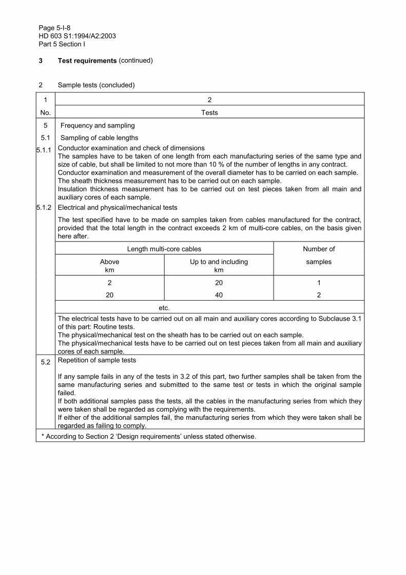
Page 5-I-8 HD 603 S1:1994/A2:2003 Part 5 Section I
3 Test requirements (continued)
2 Sample tests (concluded)
1 2
No. Tests
5 Frequency and sampling
5.1 Sampling of cable lengths
5.1.1 Conductor examination and check of dimensions The samples have to be taken of one length from each manufacturing series of the same type and size of cable, but shall be limited to not more than 10 % of the number of lengths in any contract. Conductor examination and measurement of the overall diameter has to be carried on each sample. The sheath thickness measurement has to be carried out on each sample. Insulation thickness measurement has to be carried out on test pieces taken from all main and auxiliary cores of each sample.
5.1.2 Electrical and physical/mechanical tests
The test specified have to be made on samples taken from cables manufactured for the contract, provided that the total length in the contract exceeds 2 km of multi-core cables, on the basis given here after.
Length multi-core cables Number of
Above km
Up to and including km
samples
2 20 1
20 40 2
etc.
The electrical tests have to be carried out on all main and auxiliary cores according to Subclause 3.1 of this part: Routine tests. The physical/mechanical test on the sheath has to be carried out on each sample. The physical/mechanical tests have to be carried out on test pieces taken from all main and auxiliary cores of each sample.
5.2 Repetition of sample tests If any sample fails in any of the tests in 3.2 of this part, two further samples shall be taken from the same manufacturing series and submitted to the same test or tests in which the original sample failed. If both additional samples pass the tests, all the cables in the manufacturing series from which they were taken shall be regarded as complying with the requirements. If either of the additional samples fail, the manufacturing series from which they were taken shall be regarded as failing to comply.
* According to Section 2 Design requirements unless stated otherwise.

Page 5-I-9 HD 603 S1:1994/A2:2003
Part 5 Section I
3 Test requirements (continued) 3 Type tests (electrical)
1 2 3 4
No. Tests Requirements * Test methods
1 Conductor resistance Ref. no. 1.5 HD 605 Subclause 3.1.1
2 High voltage test on complete cable ** - Test voltage (a.c.) - Duration of test - Test results
4 kV 5 min No breakdown
Four core cable without auxiliary cores: a) red and blue yellow, yellow/blue and earth b) yellow and yellow/blue red, blue and earth c) two adjacent cores remaining cores and earth
Four core cable with auxiliary cores: a) red and blue yellow, yellow/blue, all auxiliary cores and earth b) yellow and yellow/blue red, blue, all auxiliary cores and earth c) two adjacent cores and all auxiliary cores remaining cores and earth
3 High voltage test on all cores in water - Length of sample - Temperature of water - Duration of water immersion - Test voltage main cores auxiliary cores - Voltage application time - Test result
10 m 20 ± 5 °C ≥ 16 and ≤ 24 h 2,5 kV 1,5 kV 15 min No breakdown
HD 605 Subclause 3.2.2.2
4 Insulation resistance test at 90 °C - Length of sample - Temperature of water - Duration of water immersion - Test result
10 m 90 + 2 °C ≥ 2 h HD 603-1 Table 2A, type DIX3.
HD 605 Subclause 3.3.1
* According to Section 2 Design requirements unless stated otherwise. ** Concentric conductor or armour, if present, shall be connected to earth.
4 Type tests (non-electrical)
1 2 3 4
No. Tests Requirements * Test methods
1 Constructional characteristics Section 2 and HD 603-1, Clause 5
Visual inspection
1.1 General construction of cable
1.2 Core identification Ref. No. 2.3
1.3 Marking HD 603-1, Clause 3 and ref. no. 6
2 Aluminium conductors
2.1 Condition of surface Ref. no. 1.2.1a Visual inspection
2.2 Tensile properties Ref. no. 1.3 HD 605, Subclause 2.3.1.2
* According to Section 2 Design requirements unless stated otherwise.

Page 5-I-10 HD 603 S1:1994/A2:2003 Part 5 Section I
3 Test requirements (continued) 4 Type tests (non-electrical, continued)
1 2 3 4
No. Tests Requirements * Test methods
3 Tests on insulation of main conductors
3.1 Application to conductor HD 603-1 Subclause 5.2.2
Inspection and manual test
3.2 Thickness Ref. no. 2.2. EN 60811-1-1, Subclause 8.1 and HD 605, Subclause 2.1.1
3.3 Mechanical properties - before ageing - after ageing
HD 603-1 Table 2A, type DIX3
EN 60811-1-1, Subclause 9.1 EN 60811-1-2, Subclause 8.1 3.1 and EN 60811-1-1, Subclause 9.1
3.4 3.4.1 3.4.2
Ageing on complete cores followed by low temperature test duration: 7 X 24h temperature: (150 ± 3) °C - Cold elongation test at -25 °C (for diameter > 12,5 mm) - Cold bending test at -25 °C (for diameter ≤ 12,5 mm)
HD 603-1 Table 2A, type DIX3 ≥ 30 % Absence of cracks
EN 60811-1-2, Subclause 8.1 3.4.a) and b) or Subclause 8.1.3.5 depending on core diameter EN 60811-1-4, Subclause 8.3 EN 60811-1-4, Subclause 8.1
3.5 Mechanical properties after ageing of complete cable
HD 603-1 Table 2A, type DIX3
EN 60811-1-2, Subclause 8.1.4 and EN 60811-1-2, Subclause 9.1
3.6 Hot set test HD 603-1 Table 2A, type DIX3
EN 60811-2-1, Clause 9
3.7 Water absorption test HD 603-1 Table 2A, type DIX3
EN 60811-1-3, Subclause 9.2
3.8 Shrinkage test HD 603-1 Table 2A, type DIX3
EN 60811-1-3, Clause 10
4 Tests on insulation of auxiliary conductors
4.1 Thickness Ref. no. 2.2 EN 60811-1-1, Subclause 8.1 and HD 605, Subclause 2.1.1
4.2 Mechanical properties - before ageing
HD 603-1 Table 2A, type DIX3
EN 60811-1-1, Subclause 9.1
5 Tests on inner covering
5.1 Thickness Ref. no. 4.1 EN 60811-1-1, Subclause 8.2 and HD 605, Subclause 2.1.2

Page 5-I-11 HD 603 S1:1994/A2:2003
Part 5 Section I
3 Test requirements (concluded) 4 Type tests (non-electrical) (concluded)
1 2 3 4
No. Tests Requirements * Test methods
6 Tests on sheath
6.1 Thickness Ref. no. 5.2 EN 60811-1-1, Subclause 8.2 and HD 605, Subclause 2.1.2
6.2 Mechanical properties - before ageing - after ageing
HD 603-1, Table 4Atype DMV15
EN 60811-1-1 Subclause 9.2 EN 60811-1-2, Subclause 8.1 and EN 60811-1-1, Subclause 9.2
6.3 Mechanical properties - after ageing of complete cable
HD 603-1, Table 4Atype DMV15
EN 60811-1-2, Subclause 8.1 4 and EN 60811-1-1, Subclause 9.2
6.4 Loss of mass HD 603-1, Table 4Atype DMV15
EN 60811-3-2, Subclause 8.2
6.5 Pressure test at 90 °C HD 603-1, Table 4Atype DMV15
EN 60811-3-1, Subclause 8.2
6.6 Cold elongation test at -15 °C HD 603-1, Table 4Atype DMV15
EN 60811-1-4, Subclause 8.4
6.7 Cold impact test at -15 °C HD 603-1, Table.4A. type DMV15
EN 60811-1-4, Subclause 8.5
6.8 Heat shock test at 150 °C HD 603-1 Table 4Atype DMV15
EN 60811-3-1, Subclause 9.2
7 Bending test on complete cable at 0 °C, followed by voltage test of 7,5 kV for 10 min
No breakdown and no visible damage
HD 605, Subclause 2.4.1.1. but at (0 ± 2) °C, 3 complete turns and on a cylinder diameter 12 x cable diameter
8 Flame retardance test on complete cable
EN 50265-1 and EN 50265-2-1
EN 50265-1 and EN 50265-2-1
* According to Section 2 Design requirements unless stated otherwise.
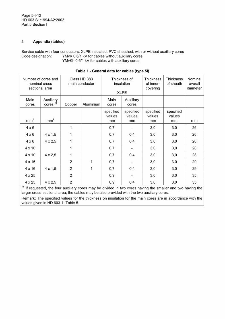
Page 5-I-12 HD 603 S1:1994/A2:2003 Part 5 Section I
4 Appendix (tables) Service cable with four conductors, XLPE insulated, PVC sheathed, with or without auxiliary cores Code designation: YMvK 0,6/1 kV for cables without auxiliary cores YMvKh 0,6/1 kV for cables with auxiliary cores
Table 1 - General data for cables (type 5I)
Number of cores and nominal cross sectional area
Class HD 383 main conductor
Thickness of insulation
XLPE
Thickness of inner-covering
Thickness of sheath
Nominal overall
diameter
Main cores
Auxiliary cores 1)
Copper
Aluminium
Main cores
Auxiliary cores
mm2
mm2
specified values
mm
specified values
mm
specified values
mm
specified values
mm
mm
4 x 6 1 0,7 - 3,0 3,0 26
4 x 6 4 x 1,5 1 0,7 0,4 3,0 3,0 26
4 x 6 4 x 2,5 1 0,7 0,4 3,0 3,0 26
4 x 10 1 0,7 - 3,0 3,0 28
4 x 10 4 x 2,5 1 0,7 0,4 3,0 3,0 28
4 x 16 2 1 0,7 - 3,0 3,0 29
4 x 16 4 x 1,5 2 1 0,7 0,4 3,0 3,0 29
4 x 25 2 0,9 - 3,0 3,0 35
4 x 25 4 x 2,5 2 0,9 0,4 3,0 3,0 35 1) If requested, the four auxiliary cores may be divided in two cores having the smaller and two having the larger cross-sectional area; the cables may be also provided with the two auxiliary cores. Remark: The specified values for the thickness on insulation for the main cores are in accordance with the values given in HD 603-1, Table 5.

Page 5-I-13 HD 603 S1:1994/A2:2003
Part 5 Section I
4 Appendix Guide to use
1 Scope
This "Guide to use" is applicable to cables according to Section 5-I of HD 603.
2 Object
The object of this "Guide to use" is to provide recommendations for the storage, transport and handling of the cables.
3 Recommendations for storage, transport and handling
3.1 Delivery
When delivered on a drum the core diameter of the drum shall not be less than:
- 14 times the outer diameter of the cable.
The distance between the outer cable layer and the head of the drum flange shall be sufficiently high to avoid damages to the cable.
Short cable lengths may be coiled to rings and transported and stored horizontally. The bending radii shall not be less than the above mentioned values.
3.2 Cable end sealing
The cable ends shall be sealed waterproof during transport, storage and laying.
3.3 Transport
For the transport of filled up cable reels only suitable carriers shall be used.
Cables stored at temperatures which fall below those recommended for installation shall not be subject to any mechanical stress including shocks, impact, bending and torsion.
It shall be prevented that drum flanges come in touch with the cable of another drum.
For loading and unloading of cable drums suitable lifting and hoisting equipment shall be used; never drop a drum on the ground or on a buffer.
See also relevant figures.
Filled up cable drums shall be rolled only on short distances over plain solid ground in the direction indicated.
The cable end shall be tightened.
3.4 Lowest temperature for cable laying and installation
Sheath of PVC is liable to cracking at low temperatures in case of blows to the cable or excessive bending. Care should therefore be taken during transport, laying and installation. Lowest temperature of cable during installation is 0 °C under normal conditions of care.
This temperature is valid for the cable itself and not for the environment. If possible, the temperature of the cable shall be raised to at least + 10 °C before laying, e.g. in a heated building, to facilitate handling and to reduce the risk of damages.
3.5 Pulling loads
It is assumed that the cable route is well designed for the laying procedure with well established curves and a sufficient number of cable rollers. Special attention shall be paid to the required minimum bending radii (see Subclause 3.6 of this appendix). The pulling forces shall be permanently supervised during the pull-in procedure.
The pulling force shall be evenly divided over the main conductors.
The maximum pulling force (P) shall be calculated as follows:
P = S σ

Page 5-I-14 HD 603 S1:1994/A2:2003 Part 5 Section I
4 Appendix Guide to use (continued)
where P is in N
σ is maximum tensile stress in conductor, viz.
50 N / mm2 for copper conductor
30 N / mm2 for aluminium conductors
S is total cross-sectional area in mm2 of the main conductors (ignoring screens, concentric conductors and auxiliary conductors).
In case of using a cable stocking, the total pulling force shall not exceed 1 000 N.
3.6 Bending radius
During installation the internal bending radius of the cable shall not be smaller than 10 D, where D is the overall diameter of the cable. This value may be reduced to 8 D in case of a careful, one single time bending of the cable end.
Bending nearby the temperature limits given in Subclause 3.4 of this appendix should be carried out extra carefully.

Page 5-I-15 HD 603 S1:1994/A2:2003
Part 5 Section I
4 Appendix -Guide to use (concluded) STORAGE
Keep the drum standing Only drums with protection Never lay them flat upright, using wedges lagging may in the heels of the be piled flange on flange. flanges Lower layer to be secured over full drum width.
TRANSPORT
Roll the drum in the Drums may be lifted either direction used during by crane or fork-lift truck cable reeling
DE-REELING
De-reel in this way Never de-reel in this way
RE-WINDING
Recommended Not recommended

Page 5-I-16 HD 603 S1:1994/A2:2003 Part 5 Section I
BLANK PAGE

Page 5-O-0 HD 603 S1:1994/A2:2003
Part 5 Section O
SECTION 5-O - CABLES WITHOUT CONCENTRIC CONDUCTOR (TYPE 5O)
Replace Section 5-O
by the following A2 referred new Section 5-O:


Page 5-O-1 HD 603 S1:1994/A2:2003
Part 5 Section O
SECTION 5-O - CABLES WITHOUT CONCENTRIC CONDUCTOR (TYPE 5O)

Page 5-O-2 HD 603 S1:1994/A2:2003 Part 5 Section O
CONTENTS 1 General--------------------------------------------------------------------------------------------------------------------------- 3
2 Design requirements---------------------------------------------------------------------------------------------------------- 4
1 Conductor ------------------------------------------------------------------------------------------------------------- 4 1.1 Material 1.2 Dimensions of circular conductors 1.3 Dimensions of sector-shaped conductors 1.4 Conductor resistance 1.5 Permissible conductor types 1.6 Preferred number of conductors and conductor cross sections
2 Insulation -------------------------------------------------------------------------------------------------------------- 4 2.1 Material 2.2 Insulation thickness 2.3 Form of insulation on sector shaped conductors 2.4 Core identification
3 Assembly of cores--------------------------------------------------------------------------------------------------- 4 3.1 Assembly
4 Inner covering -------------------------------------------------------------------------------------------------------- 4 4.1 Design 4.2 Thickness
5 Oversheath ----------------------------------------------------------------------------------------------------------- 5 5.1 Material 5.2 Colour 5.3 Thickness
6 Over-diameter-------------------------------------------------------------------------------------------------------- 5
7 Marking ---------------------------------------------------------------------------------------------------------------- 5 7.1 Indication of origin 7.2 Additional marking 7.3 Continuity of marks 7.4 Durability 7.5 Legibility 7.6 Meter marking
8 Code designation---------------------------------------------------------------------------------------------------- 6
3 Test requirements ------------------------------------------------------------------------------------------------------------- 6
1 Routine tests --------------------------------------------------------------------------------------------------------- 6
2 Sample tests---------------------------------------------------------------------------------------------------------- 6
3 Type tests, electrical------------------------------------------------------------------------------------------------ 7
4 Type tests, non-electrical ------------------------------------------------------------------------------------------ 8
4 Appendix (tables) -------------------------------------------------------------------------------------------------------------10
5 Guide to use -------------------------------------------------------------------------------------------------------------------11

Page 5-O-3 HD 603 S1:1994/A2:2003
Part 5 Section O
REFERENCES
References are made in Section 5-O of HD 603, to other parts of this HD and to other Harmonization Documents and International Standards as follows:
HD 383 Conductors of insulated cables First supplement: Guide to the dimensional limits of circular conductors (endorsing IEC 60228 and 60228A)
HD 605 Electric cables Additional test methods
EN 50265 (series) Common test methods for cables under fire conditions Test for resistance to vertical flame propagation for a single insulated conductor or cable
EN 50334 Marking by inscription for the identification of cores of electric cables
EN 60811 (series) Insulating and sheathing materials of electric cables Common test methods
In all cases reference to another HD or International Standard implies the latest edition of that document.
1 General This standard specifies the construction, dimensions and test requirements of power cables with XLPE-insulation and without concentric conductor for rated voltage (U) of 1 kV for fixed installations. The design with PE sheath (SE-N1XE) shall be designed with non halogenated materials. All components shall be lead free.
(a) Conductors
Cables with cross sections of 10 and 16 mm2 shall be made with four or five conductors. Cables with cross sections of 50, 95, 150 or 240 mm2 shall be made with four conductors. See appendix, Table 1.
(b) Insulating materials
The insulation covered by this standard shall consist of cross-linked polyethylene DIX 3 and correspond to Table 2A of HD 603-1.
(c) Rated voltage
0,6/1 kV
Definitions: see HD 603-1, Subclause 2.3
(d) Highest rated temperatures for the different types of insulating compound
Normal operation 90 °C
(e) Sheathing material
Shall be suitable for the maximum rated conductor temperature. It shall consist of PVC DMV 21, lead free, or PE type DMP 7 and correspond to Table 4A or 4B of HD 603-1 (Subclause 5.1).
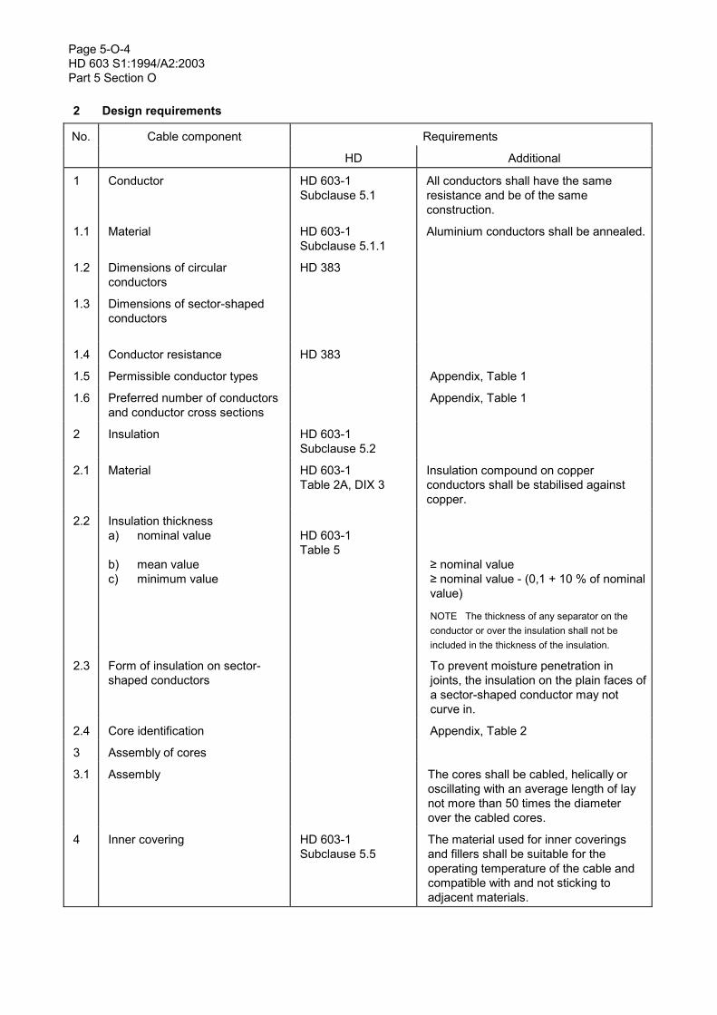
Page 5-O-4 HD 603 S1:1994/A2:2003 Part 5 Section O
2 Design requirements
No. Cable component Requirements
HD Additional
1 Conductor HD 603-1 Subclause 5.1
All conductors shall have the same resistance and be of the same construction.
1.1 Material HD 603-1 Subclause 5.1.1
Aluminium conductors shall be annealed.
1.2 Dimensions of circular conductors
HD 383
1.3 Dimensions of sector-shaped conductors
1.4 Conductor resistance HD 383
1.5 Permissible conductor types Appendix, Table 1
1.6 Preferred number of conductors and conductor cross sections
Appendix, Table 1
2 Insulation HD 603-1 Subclause 5.2
2.1 Material HD 603-1 Table 2A, DIX 3
Insulation compound on copper conductors shall be stabilised against copper.
2.2 Insulation thickness a) nominal value b) mean value c) minimum value
HD 603-1 Table 5
≥ nominal value ≥ nominal value - (0,1 + 10 % of nominal value)
NOTE The thickness of any separator on the conductor or over the insulation shall not be included in the thickness of the insulation.
2.3 Form of insulation on sector-shaped conductors
To prevent moisture penetration in joints, the insulation on the plain faces of a sector-shaped conductor may not curve in.
2.4 Core identification Appendix, Table 2
3 Assembly of cores
3.1 Assembly The cores shall be cabled, helically or oscillating with an average length of lay not more than 50 times the diameter over the cabled cores.
4 Inner covering HD 603-1 Subclause 5.5
The material used for inner coverings and fillers shall be suitable for the operating temperature of the cable and compatible with and not sticking to adjacent materials.
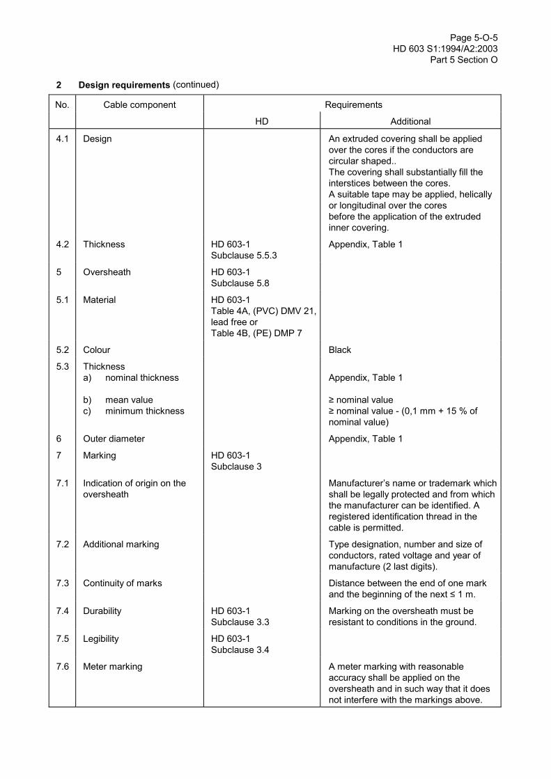
Page 5-O-5 HD 603 S1:1994/A2:2003
Part 5 Section O
2 Design requirements (continued)
No. Cable component Requirements
HD Additional
4.1 Design An extruded covering shall be applied over the cores if the conductors are circular shaped.. The covering shall substantially fill the interstices between the cores. A suitable tape may be applied, helically or longitudinal over the cores before the application of the extruded inner covering.
4.2 Thickness HD 603-1 Subclause 5.5.3
Appendix, Table 1
5 Oversheath HD 603-1 Subclause 5.8
5.1 Material HD 603-1 Table 4A, (PVC) DMV 21, lead free or Table 4B, (PE) DMP 7
5.2 Colour Black
5.3 Thickness a) nominal thickness b) mean value c) minimum thickness
Appendix, Table 1 ≥ nominal value ≥ nominal value - (0,1 mm + 15 % of nominal value)
6 Outer diameter Appendix, Table 1
7 Marking HD 603-1 Subclause 3
7.1 Indication of origin on the oversheath
Manufacturers name or trademark which shall be legally protected and from which the manufacturer can be identified. A registered identification thread in the cable is permitted.
7.2 Additional marking Type designation, number and size of conductors, rated voltage and year of manufacture (2 last digits).
7.3 Continuity of marks Distance between the end of one mark and the beginning of the next ≤ 1 m.
7.4 Durability HD 603-1 Subclause 3.3
Marking on the oversheath must be resistant to conditions in the ground.
7.5 Legibility HD 603-1 Subclause 3.4
7.6 Meter marking A meter marking with reasonable accuracy shall be applied on the oversheath and in such way that it does not interfere with the markings above.
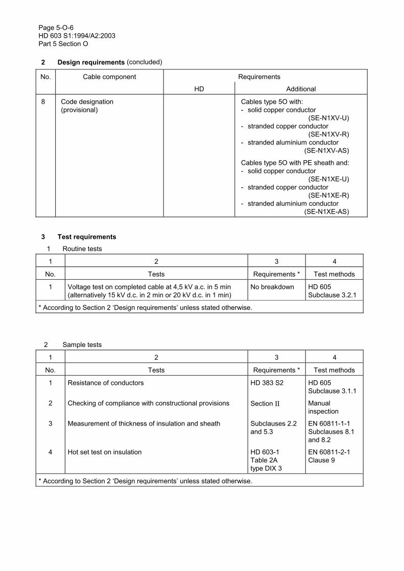
Page 5-O-6 HD 603 S1:1994/A2:2003 Part 5 Section O
2 Design requirements (concluded)
No. Cable component Requirements
HD Additional
8 Code designation (provisional)
Cables type 5O with: - solid copper conductor (SE-N1XV-U) - stranded copper conductor (SE-N1XV-R) - stranded aluminium conductor (SE-N1XV-AS)
Cables type 5O with PE sheath and: - solid copper conductor (SE-N1XE-U) - stranded copper conductor (SE-N1XE-R) - stranded aluminium conductor (SE-N1XE-AS)
3 Test requirements 1 Routine tests
1 2 3 4
No. Tests Requirements * Test methods
1 Voltage test on completed cable at 4,5 kV a.c. in 5 min (alternatively 15 kV d.c. in 2 min or 20 kV d.c. in 1 min)
No breakdown HD 605 Subclause 3.2.1
* According to Section 2 Design requirements unless stated otherwise.
2 Sample tests
1 2 3 4
No. Tests Requirements * Test methods
1 Resistance of conductors HD 383 S2 HD 605 Subclause 3.1.1
2 Checking of compliance with constructional provisions Section II Manual inspection
3 Measurement of thickness of insulation and sheath Subclauses 2.2 and 5.3
EN 60811-1-1 Subclauses 8.1 and 8.2
4 Hot set test on insulation HD 603-1 Table 2A type DIX 3
EN 60811-2-1 Clause 9
* According to Section 2 Design requirements unless stated otherwise.

Page 5-O-7 HD 603 S1:1994/A2:2003
Part 5 Section O
3 Test requirements (continued) 3 Type tests (electrical)
1 2 3 4
No. Tests Requirements * Test methods
The special tests in Section 3-2 shall also be carried out as part of the type test
1 Insulation resistance at 90 °C ≥ 1012 Ω. cm HD 605 Subclause 3.3.1
2 Voltage test on cores at 4 kV a.c. during 4 h (10 m sample)
No breakdown HD 605 Subclause 3.2.2.2
3 Surface resistance of oversheath Not less than 109 Ω
HD 605 Subclause 3.4
* According to Section 2 Design requirements unless stated otherwise.

Page 5-O-8 HD 603 S1:1994/A2:2003 Part 5 Section O
3 Test requirements (continued) 4 Type tests (non-electrical)
1 2 3 4
No. Tests Requirements * Test methods
The special tests in Section 3-2 shall also be carried out as part of the type test
1
1.1
Tests on insulation Mechanical properties before and after ageing
HD 603-1 Table 2A type DIX 3
EN 60811-1-1 Subclause 9.1 EN 60811-1-2 Subclause 8.1
2
2.1
Test on cores Shrinkage test
HD 603-1 Table 2A type DIX 3
EN 60811-1-3 Subclause 10
2.2 Water absorption HD 603-1 Table 2A type DIX 3
EN 60811-1-3 Subclause 9.2
3
3.1
Test on fillers and tapes Lead content determination test
HD 603-3, Section L Appendix 2
HD 603-3 Section L Appendix 2
4
4.1
Tests on PVC sheath Mechanical properties before and after ageing
HD 603-1 Table 4A DMV 21
EN 60811-1-1 Subclause 9.2 EN 60811-1-2 Subclause 8.1
4.2 Loss of mass test HD 603-1 Table 4A DMV 21
EN 60811-3-1 Subclause 8.2
4.3 Pressure test at high temperature HD 603-1 Table 4A DMV 21
EN 60811-3-1 Subclause 8.2
4.4 Heat shock test HD 603-1 Table 4A DMV 21
EN 60811-3-1 Subclause 9.2
4.5 Elongation test at low temperature - Samples: one set of unaged test pieces and one set of aged test pieces
HD 603-1 Table 4A DMV 21
EN 60811-1-4 Subclause 8.4 with ageing in accordance with EN 60811-1-2 Subclause 8.1.4
4.6 Lead content determination test HD 603-3 Section L Appendix 2
HD 603-3 Section L Appendix 2
* According to Section 2 Design requirements unless stated otherwise.
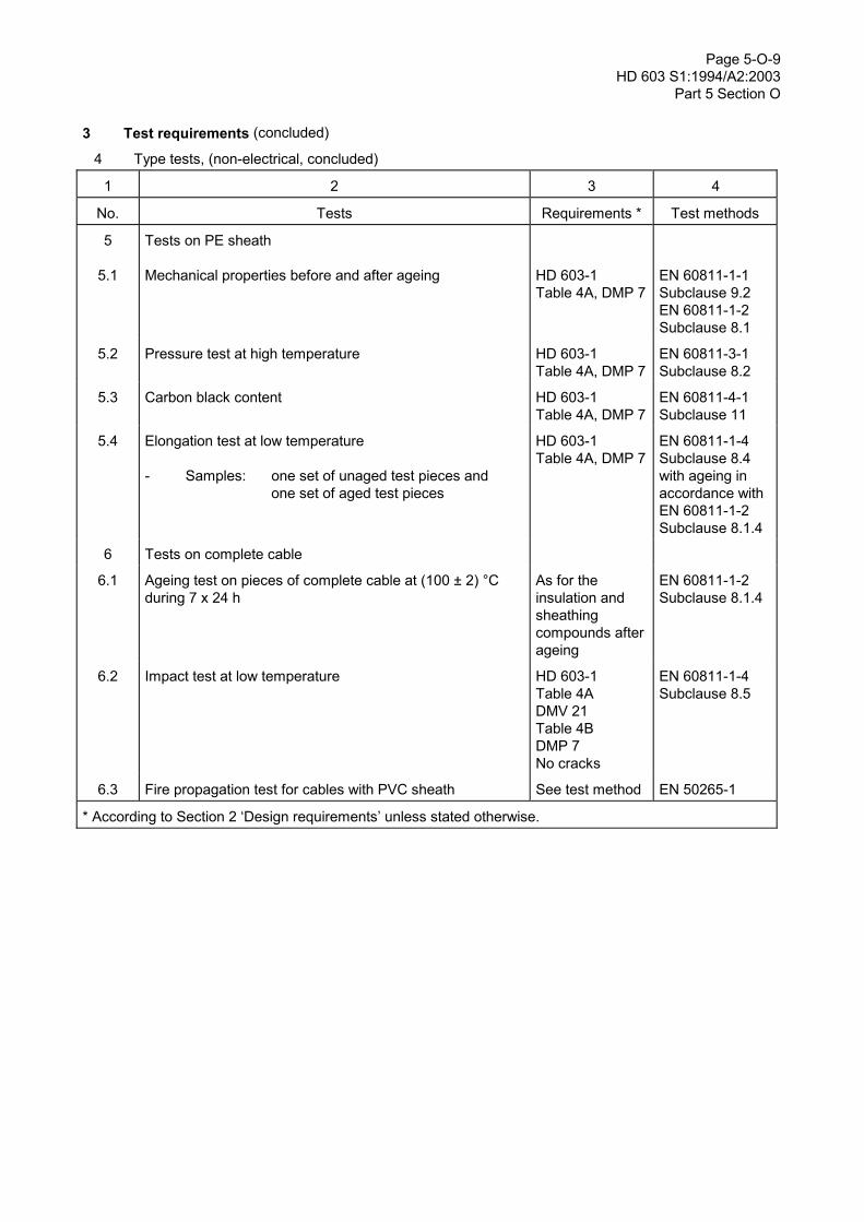
Page 5-O-9 HD 603 S1:1994/A2:2003
Part 5 Section O
3 Test requirements (concluded) 4 Type tests, (non-electrical, concluded)
1 2 3 4
No. Tests Requirements * Test methods
5
5.1
Tests on PE sheath Mechanical properties before and after ageing
HD 603-1 Table 4A, DMP 7
EN 60811-1-1 Subclause 9.2 EN 60811-1-2 Subclause 8.1
5.2 Pressure test at high temperature HD 603-1 Table 4A, DMP 7
EN 60811-3-1 Subclause 8.2
5.3 Carbon black content HD 603-1 Table 4A, DMP 7
EN 60811-4-1 Subclause 11
5.4 Elongation test at low temperature - Samples: one set of unaged test pieces and one set of aged test pieces
HD 603-1 Table 4A, DMP 7
EN 60811-1-4 Subclause 8.4 with ageing in accordance with EN 60811-1-2 Subclause 8.1.4
6 Tests on complete cable
6.1 Ageing test on pieces of complete cable at (100 ± 2) °C during 7 x 24 h
As for the insulation and sheathing compounds after ageing
EN 60811-1-2 Subclause 8.1.4
6.2 Impact test at low temperature HD 603-1 Table 4A DMV 21 Table 4B DMP 7 No cracks
EN 60811-1-4 Subclause 8.5
6.3 Fire propagation test for cables with PVC sheath See test method EN 50265-1
* According to Section 2 Design requirements unless stated otherwise.
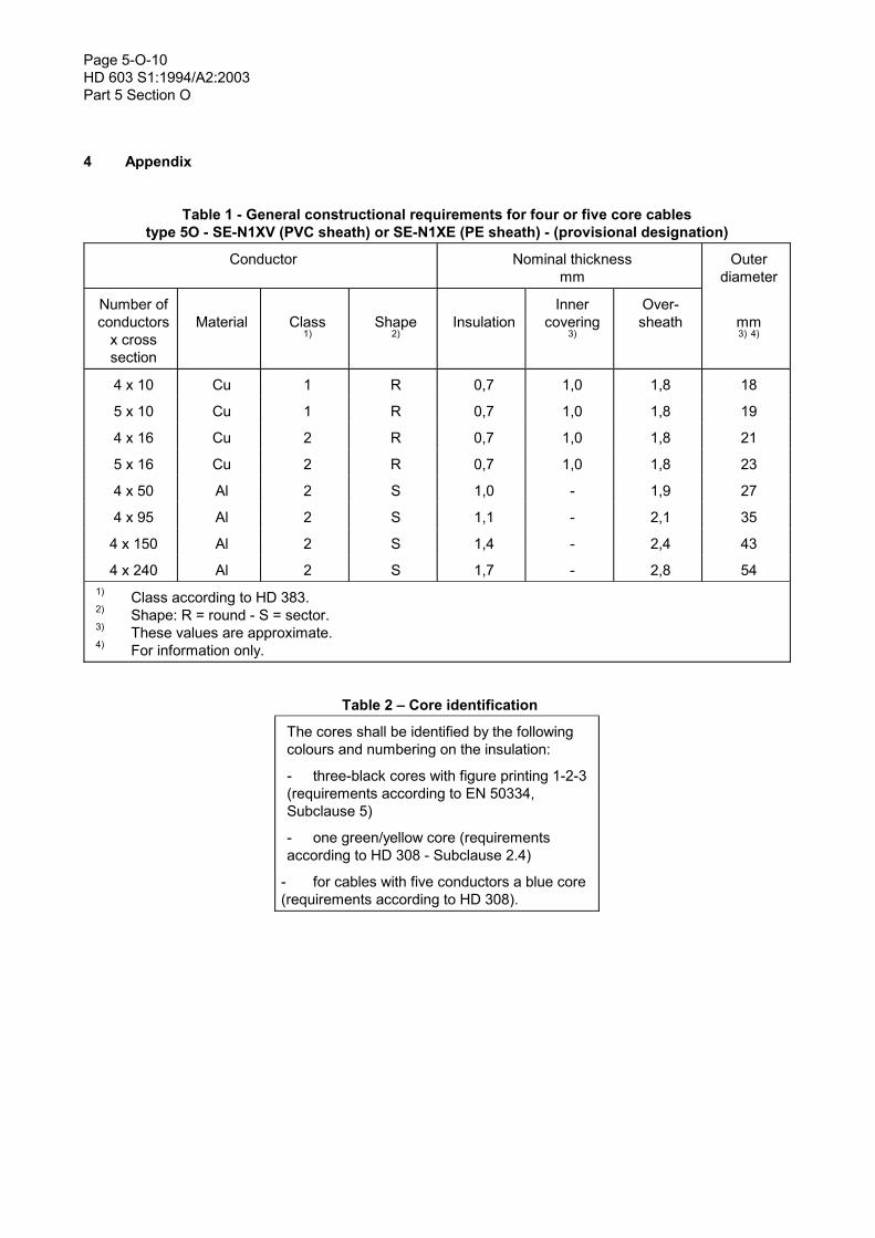
Page 5-O-10 HD 603 S1:1994/A2:2003 Part 5 Section O
4 Appendix
Table 1 - General constructional requirements for four or five core cables type 5O - SE-N1XV (PVC sheath) or SE-N1XE (PE sheath) - (provisional designation)
Conductor Nominal thickness mm
Outer diameter
Number of conductors
x cross section
Material
Class
1)
Shape
2)
Insulation
Inner covering
3)
Over- sheath
mm 3) 4)
4 x 10 Cu 1 R 0,7 1,0 1,8 18
5 x 10 Cu 1 R 0,7 1,0 1,8 19
4 x 16 Cu 2 R 0,7 1,0 1,8 21
5 x 16 Cu 2 R 0,7 1,0 1,8 23
4 x 50 Al 2 S 1,0 - 1,9 27
4 x 95 Al 2 S 1,1 - 2,1 35
4 x 150 Al 2 S 1,4 - 2,4 43
4 x 240 Al 2 S 1,7 - 2,8 54 1) Class according to HD 383. 2) Shape: R = round - S = sector. 3) These values are approximate. 4) For information only.
Table 2 Core identification
The cores shall be identified by the following colours and numbering on the insulation:
- three-black cores with figure printing 1-2-3 (requirements according to EN 50334, Subclause 5)
- one green/yellow core (requirements according to HD 308 - Subclause 2.4)
- for cables with five conductors a blue core (requirements according to HD 308).
Page 5-O-11 HD 603 S1:1994/A2:2003
Part 5 Section O
5 Guide to use
1 Scope
This "Guide to use" is applicable to cables according to Section 5-O of HD 603.
2 Object
The object of this "Guide to use" is to provide recommendations for the selection, storage, transportation and installation of the cables type 5O of HD 603.
NOTE Safety regulations are not covered in this guide as they are covered by the relevant national regulations and laws.
3 Recommendations for use
3.1 Permissible applications
The cables may be installed indoors and outdoors and may be laid in the ground and in water.
3.2 Permissible voltage
The rated voltage of the cable, expressed as Uo/U is 0,6/1 kV.
Uo is the r.m.s. value between any insulated conductor and "earth" (metal covering of the cable or the surrounding medium).
U is the r.m.s. value between any two-phase conductors of a multicore cable or of a system of single-core cables.
In an alternating current system, the nominal voltage of the system shall be not higher than the rated voltage of the cable. This condition applies both to the value Uo and to the value U.
In a direct current system, the nominal voltage of the system shall be not higher than 1,5 times the rated voltage of the cable. NOTE The operating voltage of a system may permanently exceed the nominal voltage of such a system by 10 %. A cable can be used at 10 % higher operating voltage than its rated voltage if the latter is at least equal to the nominal voltage of the system.
4 Recommendations for storage and transport
4.1 Delivery
When delivered on a drum the core diameter of the drum shall not be less than
- 16 times the outer diameter of the cable for multi-core cables,
- 20 times the outer diameter of the cable for single-core cables.
The distance between the outer cable layer and the head of the drum flange shall be sufficiently high to avoid damages to the cable.
Short cable lengths may be coiled to rings and transported and stored horizontally. The bending radii shall not be less than the values given in Subclause 5.4 below.
4.2 Cable end sealing
The cable ends shall be sealed waterproof during transport, storage and laying.
Page 5-O-12 HD 603 S1:1994/A2:2003 Part 5 Section O
5 Guide to use (continued) 4.3 Transport
For the transport of filled up cable reels only suitable carriers shall be used.
Cable drums with a total weight exceeding 2,5 tons have to be transported with the drum-axis in horizontal position. The drums have to be protected against movement. Loading and unloading shall be made by suitable devices to avoid damages of the cables and of the cable-drums.
Filled-up cable-drums shall be rolled only short distances over plain solid ground in the direction indicated. The cable ends have to be tightened.
5 Recommendations for cable laying and installation
5.1 General recommendations
The cable route, the laying method and the service conditions shall be taken into account when selecting the type of cable.
5.1.1 Cables shall be laid and operated in such a way that their properties are not endangered. In this context the following items are examples of what shall be taken into account:
- the service conditions like cable concentrations, external heat, solar radiation, heat resistance of soil, etc.;
- vibrations and movements of soil;
- protection against other outer influences like chemical solvents;
- stray currents and corrosion;
- method of laying and choice of bedding material.
5.1.2 Cables shall be protected against mechanical damages that may occur after installation. For cables laid in ground local regulations for laying depth and external protection shall be followed.
5.1.3 Inner diameters of ducts and pipes shall be chosen wide enough (1,5 - 2 times cable diameter) to allow for free movement and replacement of the cable(s).
If single-core cables of a three-phase system are installed in steel pipes or through steel constructions, all cables belonging to the same system have to pass through the same pipe or hole.
5.1.4 The cables shall be installed in such a way that the spread of fire and its consequences are limited.
5.2 Lowest temperature for cable laying
Insulation and sheath of PVC is liable to cracking at low temperatures in case of strokes against the cable or excessive bending. Care should therefore be taken during transport, laying and installation.
Lowest temperature of cable
0 °C under normal conditions of care
- 10 °C with special care in handling to avoid any strokes against the cable and with only moderate bending radius
These temperatures are valid for the cable itself and not for the environment. If possible the temperature of the cable shall be raised to at least + 10 °C before laying, e.g. in a heated building, to facilitate handling and to reduce the risk for damages.

Page 5-O-13 HD 603 S1:1994/A2:2003
Part 5 Section O
5 Guide to use (concluded) 5.3 Pulling loads
It is assumed that the cable route is well designed for the laying procedure with well established curves and a sufficient number of cable rollers. Special attention shall be paid to the required minimum bending radii (see Subclause 5.4). The pulling forces shall be permanently supervised during the pull-in procedure.
The following pulling loads shall not be exceeded:
a) pulling in the conductors of the cable
P = 50 x S N (Copper conductors)
P = 30 x S N (Aluminium conductors)
where S is the total cross section in mm2 of the conductors;
b) pulling grip around the cable oversheath
P = 5 x D2 N
where D is the outer diameter of the cable in mm.
5.4 Bending radius
During installation the bending radius shall not fall below the following values:
15 times the cable diameter for single-core cables;
12 times the cable diameter for multi-core cables.
In case of single time bending - for example in front of a terminal - it is permitted to reduce the bending radius to
10 times the cable diameter for single-core cables,
8 times the cable diameter for multi-core cables,
provided the work is made by skilled personnel, e.g. the cable is warmed up to 30 °C and the cable is bent by means of a template.

Page 5-O-14 HD 603 S1:1994/A2:2003 Part 5 Section O
BLANK PAGE
Page 5-P-0 HD 603 S1:1994/A2:2003
Part 5 Section P
SECTION 5P - CABLES WITH CONCENTRIC CONDUCTOR (TYPE 5P)
Replace Section 5-P
by the following A2 referred new Section 5-P:


Page 5-P-1 HD 603 S1:1994/A2:2003
Part 5 Section P
SECTION 5-P - CABLES WITH CONCENTRIC CONDUCTOR (TYPE 5P)

Page 5-P-2 HD 603 S1:1994/A2:2003 Part 5 Section P
CONTENTS
1 General--------------------------------------------------------------------------------------------------------------------------- 3
2 Design requirements---------------------------------------------------------------------------------------------------------- 4
1 Conductor ------------------------------------------------------------------------------------------------------------- 4 1.1 Material 1.2 Dimensions of circular conductors 1.3 Dimensions of sector-shaped conductors 1.4 Conductor resistance 1.5 Permissible conductor types 1.6 Preferred number of conductors and conductor cross sections
2 Insulation -------------------------------------------------------------------------------------------------------------- 4 2.1 Material 2.2 Insulation thickness 2.3 Form of insulation on sector shaped conductors 2.4 Core identification
3 Assembly of cores--------------------------------------------------------------------------------------------------- 4 3.1 Assembly
4 Inner covering -------------------------------------------------------------------------------------------------------- 4 4.1 Design 4.2 Thickness
5 Concentric conductor----------------------------------------------------------------------------------------------- 5 5.1 Design 5.2 Inner layer 5.3 Binder wire and binder tape 5.4 Nominal cross section 5.5 Resistance
6 Oversheath ----------------------------------------------------------------------------------------------------------- 6 6.1 Material 6.2 Colour 6.3 Thickness
7 Outer-diameter------------------------------------------------------------------------------------------------------- 6
8 Marking ---------------------------------------------------------------------------------------------------------------- 6 8.1 Indication of origin 8.2 Additional marking 8.3 Continuity of marks 8.4 Durability 8.5 Legibility 8.6 Meter marking
9 Code designation---------------------------------------------------------------------------------------------------- 7
3 Test requirements ------------------------------------------------------------------------------------------------------------- 7
1 Routine tests --------------------------------------------------------------------------------------------------------- 7
2 Sample tests---------------------------------------------------------------------------------------------------------- 7
3 Type tests, electrical------------------------------------------------------------------------------------------------ 8
4 Type tests, non-electrical ------------------------------------------------------------------------------------------ 8
4 Appendix (tables) -------------------------------------------------------------------------------------------------------------10
5 Guide to use -------------------------------------------------------------------------------------------------------------------14
Page 5-P-3 HD 603 S1:1994/A2:2003
Part 5 Section P
REFERENCES References are made in Section 5-P of HD 603, to other parts of this HD and to other Harmonization Documents and International Standards as follows:
HD 383 Conductors of insulated cables First supplement: Guide to the dimensional limits of circular conductors (endorsing IEC 60228 and 60228A)
HD 605 Electric cables Additional test methods
EN 50334 Marking by inscription for the identification of cores of electric cables
EN 60811 (series) Insulating and sheathing materials of electric cables Common test methods
IEC 60502 Power cables with extruded insulation and their accessories for rated voltages from 1kV (Um = 1,2 kV) up to 30 kV (Um = 36 kV)
In all cases reference to another HD or International Standard implies the latest edition of that document.
1 General
This standard specifies the construction, dimensions and test requirements of power cables with XLPE-insulation and with concentric conductor for rated voltage (U) of 1 kV for fixed installations.
(a) Insulating materials
The insulation covered by this standard shall consist of cross-linked polyethylene DIX 3 and correspond to Table 2A of HD 603-1.
(b) Rated voltage
0,6/1 kV
Definitions: see HD 603-1, Subclause 2.3
(c) Highest rated temperatures for the different types of insulating compound
Normal operation 90 °C
(d) Sheathing material
Shall be suitable for the maximum rated conductor temperature. It shall consist of PVC type DMV 21 or PE type DMP7 and correspond to Table 4A or 4B of HD 603-1 (see Subclause 6.1 page 5-P-6).
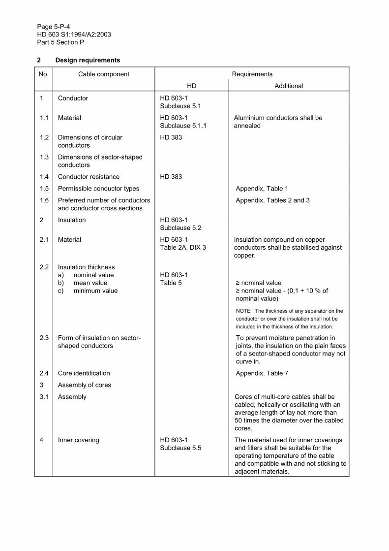
Page 5-P-4 HD 603 S1:1994/A2:2003 Part 5 Section P
2 Design requirements
No. Cable component Requirements
HD Additional
1 Conductor HD 603-1 Subclause 5.1
1.1 Material HD 603-1 Subclause 5.1.1
Aluminium conductors shall be annealed
1.2 Dimensions of circular conductors
HD 383
1.3 Dimensions of sector-shaped conductors
1.4 Conductor resistance HD 383
1.5 Permissible conductor types Appendix, Table 1
1.6 Preferred number of conductors and conductor cross sections
Appendix, Tables 2 and 3
2 Insulation HD 603-1 Subclause 5.2
2.1 Material HD 603-1 Table 2A, DIX 3
Insulation compound on copper conductors shall be stabilised against copper.
2.2 Insulation thickness a) nominal value b) mean value c) minimum value
HD 603-1 Table 5
≥ nominal value ≥ nominal value - (0,1 + 10 % of nominal value)
NOTE The thickness of any separator on the conductor or over the insulation shall not be included in the thickness of the insulation.
2.3 Form of insulation on sector-shaped conductors
To prevent moisture penetration in joints, the insulation on the plain faces of a sector-shaped conductor may not curve in.
2.4 Core identification Appendix, Table 7
3 Assembly of cores
3.1 Assembly Cores of multi-core cables shall be cabled, helically or oscillating with an average length of lay not more than 50 times the diameter over the cabled cores.
4 Inner covering HD 603-1 Subclause 5.5
The material used for inner coverings and fillers shall be suitable for the operating temperature of the cable and compatible with and not sticking to adjacent materials.

Page 5-P-5 HD 603 S1:1994/A2:2003
Part 5 Section P
2 Design requirements (continued)
No. Cable component Requirements
HD Additional
4.1 Design for a) single-core cables b) multi-core cables with round conductors c) multi-core cables with sector-shaped conductors
No inner covering required An extruded covering shall be applied over the cabled cores and substantially fill the interstices between the cores. As an alternative a lapped inner covering is permitted when the interstices are substantially filled by separate filler strings. A lapped inner covering shall be applied over the cabled cores. As an alternative an extruded inner covering is permitted. In the latter case, a helically applied tape, lapped or in open helix, may be applied over the cable cores.
4.2 Thickness HD 603-1 Subclause 5.5.3
Appendix, Table 4
5 Concentric conductor
5.1 Design In single-core cables the concentric conductor may be applied directly over the insulation. In multi-core cables, the concentric conductor shall be applied over the inner covering. The concentric conductor shall consist of an inner layer of annealed, round or flat copper wires, applied concentrically on the cable core, and an outer layer with one or more spiral binder wires or tapes of copper in contact with the wires in the inner layer.
5.2 Inner layer The inner layer shall have an average length of lay not more than 50 times the diameter over the cabled cores. The average gap between individual wires in the inner layer may not exceed 4 mm.
5.3 Binder wire and binder tape A binder wire in the outer layer shall have at least the same cross section as a wire in the inner layer. A binder tape shall have a thickness of at least 0,1 mm and width of at least 10 mm. The lay of length shall be: - for binder tape not more than 20 times - for binder wire not more than 50 times the diameter over the cabled cores.
5.4 Nominal cross section Appendix, Table 5

Page 5-P-6 HD 603 S1:1994/A2:2003 Part 5 Section P
2 Design requirements (continued)
No. Cable component Requirements
HD Additional
5.5 Resistance The electrical resistance shall be as specified in HD 383 for a Class II copper conductor of the same cross section. For cross sections not specified in HD 383 the resistance values are given in Appendix, Table 6.
6 Oversheath HD 603-1 Subclause 5.8
6.1 Material HD 603-1 preferably Table 4A, DMV 21
HD 603-1 preferably Table 4A, DMV 21, lead free
6.2 Colour Black
6.3 Thickness a) nominal thickness b) mean value c) minimum thickness
Appendix, Tables 2 and 3 For cables not specified in Tables 2 or 3, the thickness shall be calculated in accordance with the formula in IEC 60502, Subclause 12.3 a ≥ nominal value ≥ nominal value - (0,1 mm + 15 % of nominal value)
7 Outer diameter Appendix, Tables 2 and 3
8 Marking HD 603-1 Subclause 3
8.1 Indication of origin on the oversheath
Manufacturers name or trademark which shall be legally protected and from which the manufacturer can be identified. A registered identification thread in the cable is permitted.7
8.2 Additional marking Type designation, number and size of conductors, size of concentric conductor, rated voltage and year of manufacture (2 last digits)
8.3 Continuity of marks Distance between the end of one mark and the beginning of the next ≤ 1 m
8.4 Durability HD 603-1 Subclause 3.3
Marking on the oversheath must be resistant to conditions in the ground
8.5 Legibility HD 603-1 Subclause 3.4
8.6 Meter marking A meter marking with reasonable accuracy shall be applied on the oversheath and in such way that it does not interfere with the markings above.

Page 5-P-7 HD 603 S1:1994/A2:2003
Part 5 Section P
2 Design requirements (concluded)
No. Cable component Requirements
HD Additional
9 Code designation (provisional)
Cables type 5P with PVC sheath and: - solid copper conductor (EXKJ) - stranded copper conductor (FXKJ) - stranded aluminium conductor (AXKJ) Cables type 5P with PE sheath and: - solid copper conductor (EXLJ) - stranded copper conductor (FXLJ) - stranded aluminium conductor (AXLJ)
3 Test requirements 1 Routine tests
1 2 3 4
No. Tests Requirements * Test methods
1 Voltage test on completed cable at 3,5 kV a.c. in 5 min (alternatively 15 kV d.c. in 1 min)
No breakdown HD 605 Subclause 3.2.1
2 Voltage test (spark test) on the oversheath at 8 kV a.c. or 15 kV d.c.
No breakdown HD 21.2 Subclause 2.6.1
* According to Section 2 Design requirements unless stated otherwise.
2 Sample tests
1 2 3 4
No. Tests Requirements * Test methods
1 Resistance of conductors, including concentric conductors HD 383 S2 HD 605 Subclause 3.1.1
2 Checking of compliance with constructional provisions Section II Manual inspection
3 Measurement of thickness of insulation and sheath Subclauses 2.2 and 6.3
IEC 60811-1.1 Clause 8
4 Hot set test on insulation HD 603-1 Table 2A type DIX 3
IEC 60811-2.1 Clause 9
* According to Section 2 Design requirements unless stated otherwise.

Page 5-P-8 HD 603 S1:1994/A2:2003 Part 5 Section P
3 Test requirements (continued) 3 Type tests (electrical)
1 2 3 4 No. Tests Requirements * Test methods
The special tests in Section 3-2 shall also be carried out as part of the type test
1 Insulation resistance at 90 °C ≥1012 Ω.cm HD 605 Subclause 3.3.1
2 Voltage test on cores at 4 kV a.c. during 4 h (10 m sample)
No breakdown HD 605 Subclause 3.2.2.2
3 Voltage test on oversheath at 4 kV a.c. during 4 h (10 m sample immersed in the water 1 h before the test starts)
No breakdown HD 605 Subclause 3.2.3.1
* According to Section 2 Design requirements unless stated otherwise.
4 Type tests (non-electrical)
1 2 3 4 No. Tests Requirements * Test methods
The special tests in Section 3- 2 shall also be carried out as part of the type test
1
1.1
Tests on insulation Mechanical properties before and after ageing
HD 603-1 Table 2A type DIX 3
IEC 60811.1.1 Subclause 9.1 IEC 60811.1.2 Subclause 8.1
2 2.1
Test on cores Shrinkage test
HD 603-1 Table 2A type DIX 3
IEC 60811.1.3 Subclause 10
2.2 Water absorption test HD 603-1 Table 2A type DIX 3
IEC 60811.1.3 Subclause 9.1
3 3.1
Test on fillers and tapes Lead content determination test
HD 603-3 Section L Appendix 2
HD 603-3 Section L Appendix 2
4 4.1
Tests on PVC sheath Mechanical properties before and after ageing
HD 603-1 Table 4A DMV 21
IEC 60811.1.1 Subclause 9.2 IEC 60811.1.2 Subclause 8.1
4.2 Loss of mass test HD 603-1 Table 4A DMV 21
IEC 60811.3.2 Subclause 8.2
4.3 Pressure test at high temperature HD 603-1 Table 4A DMV 21
IEC 60811.3.1 Subclause 8.2
4.4 Heat shock test HD 603-1 Table 4A DMV 21
IEC 60811.3.1 Subclause 9.2
* According to Section 2 Design requirements unless stated otherwise.

Page 5-P-9 HD 603 S1:1994/A2:2003
Part 5 Section P
3 Test requirements (concluded) 4 Type tests, (non-electrical) (concluded)
1 2 3 4
No. Tests Requirements * Test methods
4.5 Elongation test at low temperature HD 603-1 Table 4A, DMV 21
IEC 60811.1.4 Subclause 8.4
4.6 Lead content determination test HD 603-3 Section L Appendix 2
HD 603-3 Section L Appendix 2
5 Tests on PE sheath
5.1 Mechanical properties before and after ageing HD 603-1 Table 4B, DMP 7
IEC 60811.1.1 Subclause 9.2 & IEC 60811.1.2 Subclause 8.1
5.2 Pressure test at high temperature HD 603-1 Table 4B, DMP 7
IEC 60811.3.1 Subclause 8.2
5.3 Carbon black content HD 603-1 Table 4B, DMP 7
IEC 60811.4.1 Subclause 11
5.4 Elongation test at low temperature HD 603-1 Table 4B, DMP 7
IEC 60811.1.4 Subclause 8.4
6 Tests on complete cable
6.1 Ageing test on pieces of complete cable at (100 ± 2) °C during 7 x 24 h
As for the insulation and sheathing compounds after ageing
IEC 60811.1.2 Subclause 8.1.4
6.2 Impact test at low temperature HD 603-1 Table 4A, DMV 21Table 4B, DMP 7 No cracks
IEC 60811.1.4 Subclause 8.5
6.3 Fire propagation test for cables with PVC sheath
No visible damages on test specimen within 300 mm from its upper end (soot, changes in colour, brittleness or cracks, as well as marks from the fixing devices are not considered to be damaged).
HD 605 Subclause 4.1.5

Page 5-P-10 HD 603 S1:1994/A2:2003 Part 5 Section P
4 Appendix
Table 1 - Range of conductor types, sizes and shapes and number of conductors covered by the specification
Conductor material Number of conductors Cross section mm2
Shape
1 2,5 - 1 000 Round 2 2,5 - 16 Round 3 2,5 - Round
Copper 25 - 400 Sector 1) 4 2,5 - 16 Round 25 - 400 Sector 1) 1 16 - 1 000 Round 2 16 Round 3 16 Round
Aluminium 25 - 400 Sector 1) 4 16 Round 25 - 400 Sector 1)
1) 25 and 35 mm2 conductors may be round as alternative.

Page 5-P-11 HD 603 S1:1994/A2:2003
Part 5 Section P
4 Appendix (continued) Table 2 - General constructional requirements for preferred designs of cables
with copper conductors Number of conductors x cross section / concentric conductor
Conductor
Oversheath nominal thickness
Outer diameter 3) approximate
mm2 Class 1) Shape 2) mm mm 1 x 2,5 /2,5 1 R 1,4 8
4/4 1 R 1,4 10 6/6 1 R 1,4 11
10/10 1 R 1,4 12 16/16 2 R 1,4 13
2 x 2,5 /2,5 1 R 1,8 13
4/4 1 R 1,8 15 6/6 1 R 1,8 16
10/10 1 R 1,8 18 16/16 2 R 1,8 21
3 x 2,5 /2,5 1 R 1,8 13
4/4 1 R 1,8 15 6/6 1 R 1,8 17
10/10 1 R 1,8 19 16/16 2 R 1,8 22 25/16 2 S 4) 1,8 23 35/16 2 S 4) 1,8 25 50/25 2 S 1,9 28 70/35 2 S 2,0 31 95/50 2 S 2,2 36
120/70 2 S 2,3 39 150/70 2 S 2,4 43 185/95 2 S 2,6 47
240/120 2 S 2,8 52 4 x 2,5 /2,5 1 R 1,8 14
4/4 1 R 1,8 16 6/6 1 R 1,8 18
10/10 1 R 1,8 21 16/16 2 R 1,8 24 25/16 2 S 4) 1,8 25 35/16 2 S 4) 1,8 27 50/25 2 S 2,0 32 70/35 2 S 2,1 35 95/50 2 S 2,3 40
120/70 2 S 2,4 43 150/70 2 S 2,6 48 185/95 2 S 2,7 52
240/120 2 S 2,9 58 1) Class according to HD 383 3) For information only 2) Shape: R = Round S = Sector 4) May be round as alternative

Page 5-P-12 HD 603 S1:1994/A2:2003 Part 5 Section P
4 Appendix (continued) Table 3 - General constructional requirements for preferred designs of cables with sector shaped aluminium conductors and with PVC sheath
Number of conductors x cross section / concentric conductor 1)
Oversheath nominal thickness
Outer diameter 2) approximate
mm2 mm mm 3 x 50/15 1,9 28
70/21 (*) 2,0 31 95/29 2,1 35
120/41 (*) 2,3 38 150/41 2,4 42
185/57 (*) 2,6 47 240/72 2,8 52
300/88 (*) 3,0 57 4 x 50/15 2,0 31
70/21 (*) 2,1 34 95/29 2,3 40
120/41 (*) 2,4 43 150/41 2,6 48
185/57 (*) 2,7 52 240/72 2,9 58
300/88 (*) 3,2 65 1) Cable with (*) should only be chosen as a second alternative. 2) For information only.
Table 4 Thickness of extruded or lapped inner covering
Fictitious diameter over laid up cores
Thickness of extruded inner covering
(approximate values)
Above Up to and including
mm mm mm
- 25 1,0
25 35 1,2
35 45 1,4
45 60 1,6
60 80 1,8
80 - 2,0
The approximate thickness of lapped covering shall be 0,4 mm for fictitious diameters over laid-up cores up to and including 40 mm and 0,6 mm for larger diameters.

Page 5-P-13 HD 603 S1:1994/A2:2003
Part 5 Section P
4 Appendix (continued)
Table 5 - Cross section of concentric conductor
Cross section of insulated
conductor(s)
Cross section of concentric conductor mm2
Insulated conductor(s) of copper Insulated conductor(s) of aluminium
mm2 1 conductor 2-4 conductors 1 conductor 2-4 conductors
2,5 2,5 2,5
4 4 4
6 6 6
10 10 10
16 16 16 10 10
25 16 16 10 10
35 16 16 10 10
50 25 25 15 15
70 35 35 21 21
95 50 50 29 29
120 50 70 41 41
150 50 70 41 41
185 50 95 50 57
240 50 120 50 72
300 50 150 50 88
400 50 185 50 111
500 50 50
630 50 50
800 50 50
1 000 50 50
Table 6 - Electrical resistance at 20 °C of concentric conductors of cross sections not specified in HD 383
Cross section of concentric conductors
Maximum resistance
mm2 Ω/km
15 1,20
21 0,868
29 0,641
41 0,443
57 0,320
72 0,253
88 0,206
111 0,164

Page 5-P-14 HD 603 S1:1994/A2:2003 Part 5 Section P
4 Appendix (concluded)
Table 7 - Core identification The cores shall be identified by the following colours and numbering on the insulation:
- black cores with figure printing 1-2-3-4, depending on the number of conductors (requirements according to EN 50334, Clause 5.), single-core cables need no figure;
- alternatively colour identification without figures is permitted with the following colours
for figure:
1: black (marking with a white stripe may be used); 2: brown; 3: black; 4: blue.
If marking with a white stripe is used, the width of the stripe shall not be less than 0,5 mm and not more than 5 % of the circumference of the core.
5 Guide to use 1 Scope
This "Guide to use" is applicable to cables according to 5-P of HD 603.
2 Object
The object of this "Guide to use" is to provide recommendations for the selection, storage, transportation and installation of the cables type 5P.
NOTE Safety regulations are not covered in this guide as they are covered by the relevant national regulations and laws.
3 Recommendations for use
3.1 Permissible applications
The cables may be installed indoors and outdoors and may be laid in the ground and in water.
3.2 Permissible voltage
The rated voltage of the cable, expressed as Uo/U, is 0,6/1 kV.
Uo is the r.m.s. value between any insulated conductor and "earth" (metal covering of the cable or the surrounding medium);
U is the r.m.s. value between any two-phase conductors of a multicore cable or of a system of single-core cables.
In an alternating current system, the nominal voltage of the system shall be not higher than the rated voltage of the cable. This condition applies both to the value Uo and to the value U.
In a direct current system, the nominal voltage of the system shall be not higher than 1,5 times the rated voltage of the cable.
NOTE The operating voltage of a system may permanently exceed the nominal voltage of such a system by 10 %. A cable can be used at 10 % higher operating voltage than its rated voltage if the latter is at least equal to the nominal voltage of the system.
Page 5-P-15 HD 603 S1:1994/A2:2003
Part 5 Section P
5 Guide to use (continued) 3.3 Concentric conductor
The concentric conductor may be used as neutral, PE-conductor, PEN-conductor or as a screen.
4 Recommendations for storage and transport
4.1 Delivery
When delivered on a drum the core diameter of the drum shall not be less than
- 16 times the outer diameter of the cable for multi-core cables,
- 20 times the outer diameter of the cable for single-core cables.
The distance between the outer cable layer and the head of the drum flange shall be sufficiently high to avoid damages to the cable.
Short cable lengths may be coiled to rings and transported and stored horizontally. The bending radii shall not be less than the values given in Sublause 5.4 below.
4.2 Cable end sealing
The cable ends shall be sealed waterproof during transport, storage and laying.
4.3 Transport
For the transport of filled up cable reels only suitable carriers shall be used.
Cable drums with a total weight exceeding 2,5 tons have to be transported with the drum-axis in horizontal position. The drums have to be protected against movement. Loading and unloading shall be made by suitable devices to avoid damages of the cables and of the cable-drums.
Filled-up cable-drums shall be rolled only short distances over plain solid ground in the direction indicated. The cable ends have to be tightened.
5 Recommendations for cable laying and installation
5.1 General recommendations
The cable route, the laying method and the service conditions shall be taken into account when selecting the type of cable.
5.1.1 Cables shall be laid and operated in such a way that their properties are not endangered. In this context the following items are examples of what shall be taken into account:
- the service conditions like cable concentrations, external heat, solar radiation, heat resistance of soil, etc.;
- vibrations and movements of soil;
- protection against other outer influences like chemical solvents;
- stray currents and corrosion;
- method of laying and choice of bedding material.
5.1.2 Cables shall be protected against mechanical damages that may occur after installation. For cables laid in ground local regulations for laying depth and external protection shall be followed.
5.1.3 Inner diameters of ducts and pipes shall be chosen wide enough (1,5 - 2 times cable diameter) to allow for free movement and replacement of the cable(s).
If single-core cables of a three-phase system are installed in steel pipes or through steel constructions, all cables belonging to the same system have to pass through the same pipe or hole.
Page 5-P-16 HD 603 S1:1994/A2:2003 Part 5 Section P
5 Guide to use (concluded) 5.1.4 The cables shall be installed in such a way that the spread of fire and its consequences are limited.
5.2 Lowest temperature for cable laying
Sheath of PVC is liable to cracking at low temperatures in case of strokes against the cable or excessive bending. Care should therefore be taken during transport, laying and installation.
Lowest temperature of cable
0 °C under normal conditions of care
- 10 °C with special care in handling to avoid any strokes against the cable and with only moderate bending radius
These temperatures are valid for the cable itself and not for the environment. If possible the temperature of the cable shall be raised to at least + 10 °C before laying, e.g. in a heated building, to facilitate handling and to reduce the risk for damages.
5.3 Pulling loads
It is assumed that the cable route is well designed for the laying procedure with well established curves and a sufficient number of cable rollers. Special attention shall be paid to the required minimum bending radii (see Sublause 5.4). The pulling forces shall be permanently supervised during the pull-in procedure.
The following pulling loads shall not be exceeded:
a. pulling in the conductors of the cable
P = 50 x S N (Copper conductors)
P = 30 x S N (Aluminium conductors)
where S is the total cross section in mm2 of the conductors (concentric conductor not included);
b. pulling grip around the cable oversheath
P = 5 x D2 N
where D is the outer diameter of the cable in mm.
5.4 Bending radius
During installation the bending radius shall not fall below the following values:
15 times the cable diameter for single-core cables;
12 times the cable diameter for multi-core cables.
In case of single time bending - for example in front of a terminal - it is permitted to reduce the bending radius to
10 times the cable diameter for single-core cables,
8 times the cable diameter for multi-core cables,
provided the work is made by skilled personnel, e.g. the cable is warmed up to 30 °C and the cable is bent by means of a template.

Page 5-Q-0 HD 603 S1:1994/A2:2003
Part 5 Section Q
SECTION Q - CNE CABLES WITH SOLID NEUTRAL/EARTH CONDUCTOR (TYPE 5Q)
Delete Section 5-Q completely.


Page 5-R-0 HD 603 S1:1994/A2:2003
Part 5 Section R
SECTION 5-R XLPE UNARMOURED CABLES (TYPE 5R)
Replace Section 5-R by the following A2 referred new Section 5-R:

Page 5-R-1 HD 603 S1:1994/A2:2003
Part 5 Section R
SECTION 5-R - XLPE UNARMOURED CABLES (TYPE 5R)
Page 5-R-2 HD 603 S1:1994/A2:2003 Part 5 Section R
CONTENTS
1 General------------------------------------------------------------------------------------------------------------------------ 3 2 Design requirements------------------------------------------------------------------------------------------------------- 4
1 Core conductors-------------------------------------------------------------------------------------------------- 4
2 Insulation----------------------------------------------------------------------------------------------------------- 4 3 Assembly of cores ----------------------------------------------------------------------------------------------- 4 4 Neutral/earth concentric conductor ------------------------------------------------------------------------- 5
5 Oversheath-------------------------------------------------------------------------------------------------------- 5
6 Marking------------------------------------------------------------------------------------------------------------- 6
7 Sealing ------------------------------------------------------------------------------------------------------------- 6
3 Test requirements --------------------------------------------------------------------------------------------------------------- 6
1 Routine tests ------------------------------------------------------------------------------------------------------ 6
2 Sample tests ------------------------------------------------------------------------------------------------------ 7
3 Type tests --------------------------------------------------------------------------------------------------------- 8 4 Appendices------------------------------------------------------------------------------------------------------------------- 9
1 Table 1-------------------------------------------------------------------------------------------------------------- 9 2 Marking ------------------------------------------------------------------------------------------------------------10 3 Rubber layer------------------------------------------------------------------------------------------------------11
Page 5-R-3 HD 603 S1:1994/A2:2003
Part 5 Section R
REFERENCES References are made in Section 5R of HD 603, to other parts of this HD, other Harmonization Documents, European and International Standards as follows: HD 383 Conductors of insulated cables First supplement: Guide to the dimensional limits
of circular conductors (endorsing IEC 60228 and IEC 60228A)
HD 605 Electric cables Additional test methods
EN 60811 (series) Insulating and sheathing materials of electric cables Common test methods
In all cases reference to another HD, EN or International Standard implies the latest edition of that document.
1 General
This standard specifies the construction, principal dimensions and test requirements for waveform cables (type 5R) with solid aluminium core conductors, XLPE insulation and PVC oversheath.
(a) Construction types
Type 5R-1 Three-core cables with copper wire concentric neutral/earth.
Type 5R-2 Four core 3 phase cables with a separate neutral and a concentric earth conductor.
(b) Rated voltage
0,6/1 kV Definitions: see HD 603-1, Subclause 2.3
(c) Highest rated temperature for the cable
Normal operation 80 °C Short-circuit (5 sec max. duration) 250 °C
(d) Insulating material
The insulation of the phase conductors shall be XLPE corresponding to HD 603-1, Table 2A, type DIX 3.
(e) Neutral/earth conductor
The neutral/earth conductor shall comprise of copper wires laid on a single rubber layer.
(f) Sheathing material
The oversheath shall consist of PVC and correspond to HD 603-1, Table 4A, type DMV 23.
Page 5-R-4 HD 603 S1:1994/A2:2003 Part 5 Section R
(g) Sampling for thickness measurements
Measurements for thickness measurements of insulation, extruded inner covering and oversheath listed in the test requirements shall be made on a sample taken from one of each drum length of cable selected for the test, having discarded any portion which may have suffered damage. If any of the thickness measured does not comply with Subclauses 2.2, 4.3, 5.3 and 6.3 of this part, them two further samples shall be checked for the non-compliant items. If both samples met the specified requirements the cable is deemed to comply, but if either does not meet the requirements, the cable is deemed not to comply.
2 Design requirements
Requirements No. Cable component HD Additional
1. Core conductors HD 603-1 Subclause 5.1
1.1 Material HD 603-1 Subclause 5.1
Solid aluminium of the form given in Appendix 1, Table 1
1.2 Dimensions
HD 383
1.3 Tensile strength and elongation at break of solid aluminium conductor
Tensile strength: 80N/mm2
Maximum elongation at break: 25 % minimum For 35 mm2 conductors the tensile strength shall be between 95 N/mm2 and 125 N/mm2. There is no elongation requirement where the tensile strength exceeds 80 N/mm2.
1.4 DC resistance
The d.c. resistance shall conform to the values given in Appendix 1, Table 1.
2 Insulation HD 603-1 Subclause 5.2
2.1 Material HD 603-1 Subclause 5.2.1 Table 2A DIX 3
2.2 Thickness HD 603-1 Subclause 5.2.3
Appendix 1, Table 1
2.3 Core identification
The core shall be identifiable by colour as follows: - 3-core cables: red, yellow, blue, - 4-core cables: red, yellow, blue, black.
3 Assembly of cores
3.1 Laying up HD 603-1 Subclause 5.3
Cores shall be laid up with a right hand direction of lay in the sequence as given in Subclause 2.3. The lay of length of the cores is not specified. However, for cable types with 300 mm2 conductors it is recommended that a minimum lay of 1 600 mm be used.
3.2 Binder tape(s) HD 603-1 Subclause 5.4
Suitable binder tape(s) may be applied over the cores, to form a compact assembly.

Page 5-R-5 HD 603 S1:1994/A2:2003
Part 5 Section R
2 Design requirements (continued)
Requirements No. Cable component HD Additional
4 4.1
Neutral/earth concentric conductor Material
HD 603-1 Subclause 5.7
Plain annealed copper wires with a minimum elongation of 18 %
4.2 Application
The wires shall be applied concentrically with a waveform lay. The wires shall be applied such that the average gap between adjacent wires shall not exceed 4 mm and at any point the gap shall not exceed 8 mm. The developed length of each wire in the waveform wavelength shall be at least 106 %. The d.c. resistance shall conform to the values given in Appendix 1, Table 1. Example of the number and diameter of wires and the minimum lay length are given in Appendix 1, Table 1.
4.3
Copper wires bedded on a rubber layer
The copper wires shall be bedded on a layer of soft non-vulcanizable synthetic rubber which is compatible with the core insulation and PVC oversheath. The rubber layer shall be capable of being easily removed and shall fill the outer interstices of multi-core cables where these are not covered by binder tape(s). The wires shall be partially bedded in the rubber layer and the thickness of the rubber under the wires shall be approximately 1 mm.
5 Oversheath
5.1 Material HD 603-1 Subclause 5.8 Table 4A DMV 23

Page 5-R-6 HD 603 S1:1994/A2:2003 Part 5 Section R
2 Design requirements (concluded)
Requirements No. Cable component HD Additional
5.2 Colour Black
5.3 Thickness HD 603-1 Subclause 5.8.3
Appendix 1, Table 1
6 Marking Appendix 2
7 Sealing Before dispatch, the manufacturer shall cap the ends of the cable in order to form a seal to prevent the ingress of water during transportation and storage.
3 Test requirements
1 Routine tests No. Tests Requirements * Test methods 1 Conductor resistance:
- phase - combined neutral/earth (type 5R-1) - neutral (type 5R-2) - earth continuity (type 5R-2)
Appendix 1, Table 1
HD 605, Subclause 3.1.1
2 Voltage test on complete cable: - test voltage
3,5 kV a.c.
HD 605
- duration
5 min
Subclause 3.2.1
3 Spark test on insulation No failure HD 605 Subclause 3.6.1
5 Spark test on oversheath No failure HD 605 Subclause 3.6.1
6
Marking Appendix 2 Visual examination
* According to Section 2 Design requirements unless stated otherwise.

Page 5-R-7 HD 603 S1:1994/A2:2003
Part 5 Section R
3 Test requirements (continued) 2 Sample tests
No. Tests Requirements * Test methods 1 Core conductor material and construction
Clause 1 HD 605
Subclause 2.3.1.2 and by visual examination
2 Insulation: - application - thickness - colour
Clause 2 Appendix 1, Table 1 Subclause 2.3
Visual examination HD 605 Subclause 2.1.1 HD 605 Subclause 2.5.4
3
Concentric neutral/earth conductor material, construction and application
Clause 4 Visual examination and measurement
4
Rubber layer: - application - removal
Subclause 4.4 Appendix 3A
Visual examination and by measurement Appendix 3A
5 Oversheath: - application - thickness
Clause 6 Appendix 1, Table 1
Visual examination HD 605 Subclause 2.1.2
* According to Section 2 Design requirements unless stated otherwise.

Page 5-R-8 HD 603 S1:1994/A2:2003 Part 5 Section R
3 Test requirements (continued)
3 Type tests Tests Requirements Test methods 1 Insulation
- material - shrinkage
HD 603-1 Table 2A - DIX 3 Shall not exceed 4 %
EN 60811-1-1, Subclause 9.1 EN 60811-1-2, Subclause 8.1.3 EN 60811-2-1, Clause 9 EN 60811-1-3, Clause 10 and Subclause 9.2 EN 60811-1-3
2
Rubber layer: - quality - bend test
Appendix 3B No penetration of the underlying rubber
HD 605 Subclause 2.2.7 HD 605 Subclause 2.4.1.1
3 Oversheath
HD 603-1 Table 4A - DMV 23
EN 60811-1-1, Subclause 9.2 EN 60811-1-2, Subclause 8.1.3 EN 60811-3-2, Subclause 8.2 EN 60811-3-1, Subclause 8.2 EN 60811-1-4, Clause 8
4 Compatibility of complete cable
HD 603-1 Table 2A - DIX 3 & HD 603-1 Table 4A- DMV 23
HD 605, Subclause 2.4.12.2

Page 5-R-9 HD 603 S1:1994/A2:2003
Part 5 Section R
4 Appendices
1 Table 1 0,6/1kV XLPE insulated and PVC sheathed cables
Table 1a - Type 5R-1 - Three phase 3-core cables Form of phase conductor Circular Sector shaped
Nominal area of phase conductor (mm2) 35 70 95 120 185 240 300
Minimum average thickness of insulation (mm) 0,9 1,1 1,1 1,2 1,6 1,7 1,8 Minimum thickness of insulation at any point (mm) 0,71 0,89 0,89 0,98 1,34 1,43 1,52 Concentric neutral/earth conductor, e,g: approximate number of wires 26 30 30 30 42 42 42 approximate diameter of wires (mm) 1,04 1,35 1,58 1,78 1,87 1,87 1,87 approximate waveform lay length (mm) 220 220 250 270 300 375 440 Minimum average thickness of oversheath (mm) 1,8 1,9 2,1 2,2 2,5 2,7 2,8 Minimum thickness of oversheath at any point (mm) 1,43 1,51 1,68 1,77 2,02 2,19 2,28 Approximate overall diameter (mm) 26,5 30,7 34,5 38,0 45,9 50,7 55,2 Maximum d.c. resistance per km of cable at 20ºC: phase conductor (Ω) 0,868 0,443 0,320 0,253 0,164 0,125 0,100 concentric neutral/earth conductor (Ω) 0,868 0,443 0,320 0,253 0,164 0,164 0,164
Table 1b - Type 5R-2 - Three phase 4 core cables Form of core conductor Sector shaped
Nominal cross-sectional area of core conductor (mm2) 95 185 240 300
Minimum average thickness of insulation (mm) 1,1 1,6 1,7 1,8 Minimum thickness of insulation at any point (mm) 0,89 1,34 1,43 1,52 Concentric earth conductor, e,g: approximate number of wires 30 42 42 42 approximate diameter of wires (mm) 1,58 1,87 1,87 1,87 approximate waveform lay length (mm) 250 300 375 440 Minimum average thickness of oversheath (mm) 2,2 2,6 2,8 3,1 Minimum thickness of oversheath at any point (mm) 1,77 2,11 2,28 2,88 Approximate overall diameter (mm) 38,3 53,2 57,8 63,0 Maximum d.c. resistance per km of cable at 20ºC: core conductors (Ω) 0,320 0,164 0,125 0,100 concentric earth conductor (Ω) 0,320 0,164 0,164 0,164
Page 5-R-10 HD 603 S1:1994/A2:2003 Part 5 Section R
4 Appendices (contuinued)
2 Marking
1 External marking The external surface of all cables conforming to this standard shall be legibly marked with the following elements. Element Example of marking
a) Electric cable: ELECTRIC CABLE
b) Voltage designation: 600/1 000V
c) Standard number: HD 603-5R
d) Manufacturers identification XYZ
e) Number of cores, type and nominal area of phase conductors, e.g.
1) 3 x 70 AL shall indicate a 3-core cable with 70mm² aluminium phase conductors having a copper concentric neutral/earth conductor. 2) 4 x 95 AL shall indicate a 4-core cable with 95 mm² aluminium phase conductors having a copper concentric earth conductor.
The marking of the elements a) to d) shall be by embossing or indenting on the oversheath. For cables with tabulated approximate overall diameters greater than 15 mm, elements a), b) and c) shall appear, in any sequence that is deemed neither to confuse nor conflict, on two or more primary lines along the axis of the cable, approximately equally spaced around the circumference of the cable. Elements d) and e) shall appear, together or separately, in any sequence that is deemed neither to confuse nor conflict, on either one of the primary lines, or on a secondary line or lines. For cables with tabulated approximate overall diameters of 15 mm or less, the elements shall be arranged as for cables of greater than 15 mm diameter, except that the marking for elements a), b) and c) shall appear on one or more primary lines. The letters and figures shall consist of upright block characters. The characters shall have a minimum height of 3 mm. The distance between the end of one element of marking and the beginning of the next identical element shall be not greater than 550 mm for elements a), b) and c), and not greater than 1 100 mm for elements d) and e).
2 Identification of year of manufacture A means of identifying the year of manufacture of the cable shall be provided throughout the length of the cable, either internally or by marking on the surface of the cable. If the identification mark is internal, the distance between the end of one mark and the beginning of the next mark shall be not greater than 550 mm. NOTE An identification thread may be used as an alternative to internal marking. If the identification is by marking on the surface it shall conform to the requirements given in 1d) and e) in respect of the maximum distance between marks.

Page 5-R-11 HD 603 S1:1994/A2:2003
Part 5 Section R
4 Appendices (concluded)
3 The mark of an approval organisation If the mark of an approval organisation is used, it shall be provided throughout the length of the cable, either as a mark on the surface of the cable, or as an identification thread, as specified by the approval organisation. If the mark is applied to the cable, it shall be on the surface in the form of the symbol(s) specified by the approval organisation, and shall conform to the requirements given in 1d) and e) in respect of the maximum distance between marks.
4 Additional marking Where additional marking is made, it shall be throughout the length of the cable, and on the external surface of the cable, or by means of a tape or thread within the cable, or by a combination of these methods. If the additional marking is applied to the surface of the cable it shall not render illegible the marking specified in 1 to 3. The additional marking, however made, shall be repeated at intervals not exceeding 1 100 mm.
5 End markings The end of each drum length of three-phase cable at which the sequence of core colours is clockwise shall be marked red. The other end shall be marked green.
3 Rubber layer
A Removal of rubber layer
On a sample of cable approximately 200 mm in length, use a jointers plastic knife (e.g. Hepnyf) to cut longitudinally through the rubber layer and lift it away from the cores. Using the raised edge unwrap the rubber layer from the cores. The rubber layer should lift easily and cleanly away. Any remaining residue should be readily removable using the jointers plastic knife. The cable is deemed acceptable if, following removal not more than 5 % of the outer cylindrical surface area of the laid-up cores remains coated in rubber.
B Quality
When tested in accordance with HD 605, Subclause 2.2.7, the rubber layer shall meet the following requirements: (a) the value of plasticity obtained shall be not less than 50;
(g) the elongation at break before ageing shall not be less than 250 %;
(c) the elongation at break after ageing shall not be less than 150 %.

Page 5-R-12 HD 603 S1:1994/A2:2003 Part 5 Section R
BLANK PAGE

Page 5-S-0 HD 603 S1:1994/A2:2003
Part 5 Section S
SECTION 5-S SERVICE CABLES WITH CONCENTRIC CONDUCTOR (TYPE 5S)
Replace Section 5-S
by the following A2 referred new Section 5-S:


Page 5-S-1 HD 603 S1:1994/A2:2003
Part 5 Section S
SECTION 5-S SERVICE CABLES WITH CONCENTRIC CONDUCTOR (TYPE 5S)
Page 5-S-2 HD 603 S1:1994/A2:2003 Part 5 Section S
CONTENTS
1 General-------------------------------------------------------------------------------------------------------------------------- 3 2 Design requirements--------------------------------------------------------------------------------------------------------- 5
1 Phase conductors ---------------------------------------------------------------------------------------------------- 5
2 Insulation --------------------------------------------------------------------------------------------------------------- 5
3 Assembly of cores --------------------------------------------------------------------------------------------------- 5
4 Bedding for 3-phase cables---------------------------------------------------------------------------------------- 5
5 Neutral/earth concentric conductor ------------------------------------------------------------------------------ 6
6 Oversheath ------------------------------------------------------------------------------------------------------------ 7
7 Marking ----------------------------------------------------------------------------------------------------------------- 7
8 Sealing ----------------------------------------------------------------------------------------------------------------- 7
3 Test requirements ------------------------------------------------------------------------------------------------------------ 7 1 Routine tests ---------------------------------------------------------------------------------------------------------- 7 2 Sample tests----------------------------------------------------------------------------------------------------------- 8
3 Type tests -------------------------------------------------------------------------------------------------------------- 8 4 Appendices--------------------------------------------------------------------------------------------------------------------10 1 Table 1-----------------------------------------------------------------------------------------------------------------10 2 Marking ----------------------------------------------------------------------------------------------------------------14 3 Requirements for Low Smoke sheaths (cable types 5S-5 to 5S-8) -------------------------------------16 4 Shrinkage test for Low Smoke sheaths (cable types 5S-5 to 5S-8)-------------------------------------17
Page 5-S-3 HD 603 S1:1994/A2:2003
Part 5 Section S
REFERENCES References are made in Section 5S of HD 603, to other parts of this HD, other Harmonization Documents, European and International Standards as follows: HD 383 Conductors of insulated cables First supplement: Guide to the dimensional limits of
circular conductors (endorsing IEC 60228 and IEC 60228A)
HD 605 Electric cables Additional test methods
EN 50265 (series) Common test methods for cables under fire conditions Test for resistance to vertical flame propagation for a single insulated conductor or cable
EN 50266 (series) Common test methods for cables under fire conditions Test for vertical flame spread of vertically-mounted bunched wires or cables
EN 50267 (series) Common test methods for cables under fire conditions Tests on gases evolved during combustion of materials from cables
EN 50268 (series) Common test methods for cables under fire conditions Measurement of smoke density of cables burning under defined conditions
EN 60811 (series) Insulating and sheathing materials of electric cables Common test methods
In all cases reference to another HD, EN or International Standard implies the latest edition of that document. _________________________________________________________________________
General
This standard specifies the construction, principal dimensions and test requirements for
- single and three phase, XLPE insulated cables (types 5S-1 to 5S-4) having a combined concentric neutral/earth conductor and a PVC oversheath,
- single and three phase, XLPE insulated cables (types 5S-5 to 5S-8) having a combined
concentric neutral/earth conductor and a oversheath which, when assessed by the specific tests, produce lower levels of smoke and corrosive gases under exposure to fire, compared with cable types 5S-1 to 5S-4,
- single and three phase, XLPE insulated split concentric service cables (types 5S-9 to 5S-12)
where the concentric layer comprises of bare wires (earth continuity conductor) and copper wires covered with black polymeric compound (neutral conductor) and a PVC oversheath.
(a) Construction types
Type 5S-1 Single-core stranded copper phase conductor with a combined concentric copper neutral/earth Type 5S-2 Single-core solid aluminium phase conductor with a combined concentric copper neutral/earth Type 5S-3 Three-core stranded copper phase conductors with a combined concentric copper neutral/earth. Type 5S-4 Three-core solid aluminium phase conductors with a combined concentric copper neutral/earth
Page 5-S-4 HD 603 S1:1994/A2:2003 Part 5 Section S
Type 5S-5 Low Smoke single-core stranded copper phase conductor with a combined concentric copper neutral/earth Type 5S-6 Low Smoke single-core solid aluminium phase conductor with a combined concentric copper neutral/earth Type 5S-7 Low Smoke three-core stranded copper phase conductors with combined concentric copper neutral/earth Type 5S-8 Low Smoke three-core solid aluminium phase conductors with a combined concentric copper neutral/earth Type 5S-9 Single-core copper phase conductor with a split concentric copper neutral/earth conductor Type 5S-10 Single-core aluminium phase conductor with a split concentric copper neutral/earth conductor Type 5S-11 Three-core copper phase conductors with a split concentric copper neutral/earth conductor Type 5S-12 Three-core aluminium phase conductors with a split concentric copper neutral/earth conductor.
(b) Rated voltage
0,6/1 kV Definitions: see HD 603-1, Subclause 2.3
(c) Highest rated temperature for the cable
Normal operation 90 °C Maximum short-circuit temperature 250 ° C
(d) Insulating material The insulation of the phase conductors shall be XLPE corresponding to HD 603-1, Table 2A, type DIX 3.
(e) Sheathing material For construction types 5S-1 to 5S-4 and 5S-9 to 5S-12 the sheathing material shall consist of PVC corresponding to HD 603-1, Table 4A, type DMV 23. For construction types 5S-5 to 5S-8 it shall be an extruded compound complying with, and meeting the requirements as given in Appendix 3.
(f) Sampling for thickness measurements Measurements of thickness of insulation and oversheath listed in the test requirements shall be made on a sample taken from one end of each drum length of cable selected for the test, having discarded any portion which may have suffered damage. If any of the thickness measured does not comply with Subclauses 2.1.1 and 6.3 of this part, then two further samples shall be checked for the non-compliant items. If both samples meet the specified requirements the cable is deemed to comply, but if either does not meet the requirements, the cable is deemed not to comply.

Page 5-S-5 HD 603 S1:1994/A2:2003
Part 5 Section S
2 Design requirements
Requirements No. Cable component HD Additional
1. Phase conductors HD 603-1 Subclause 5.1
1.1 Material
1.1.1 Types 5S-1, 5S-3, 5S-5, 5S-9 and 5S-11
HD 603-1 Subclause 5.1
Stranded plain copper conductors of the form given in Appendix 1, Table 1
1.1.2 Types 5S-2, 5S-4, 5S-6, 5S-8, 5S-10 and 5S-12
HD 603-1 Subclause 5.1
Solid aluminium conductors of the form given in Appendix 1, Table 1
1.2 Dimensions
HD 383
1.3 Tensile strength of solid aluminium conductors
125 N/mm2 max.
1.4
DC resistance
The d.c. resistance shall conform to the values given in Appendix 1, Table 1.
2. Insulation HD 603-1 Subclause 5.2
2.1 Material HD 603-1 Subclause 5.2.1 Table 2A DIX 3
2.2 Thickness HD 603-1 Subclause 5.2.3
Appendix I, Table 1
2.3 Core identification
The cores shall be identifiable by colour as follows: - single-core: red, - three-cores: red, yellow & blue.
3 4 4.1 4.2
Assembly of cores Bedding for 3-phase cables Types 5S-1 to 5S-4 and 5S-9 to 5S-12 Types 5S-5 to 5S-8
HD 603-1 Subclauses 5.3 & 5.4 HD 603-1 Subclause 5.5
Cores of 3-core cable shall be laid-up with a right hand direction of lay and a minimum lay length of 550 mm. Fillers of suitable synthetic material may be used where necessary. A PVC or synthetic tape bedding, having an approximate total thickness of 0,5 mm shall be applied over the laid up cores of three phase cables. At the discretion of the manufacturer a polyester separation tape may be applied between the laid up cores and the PVC tape as part of the bedding. A synthetic tape bedding, having an approximate total thickness of 0,5 mm shall be applied over the laid up cores of three phase cables.
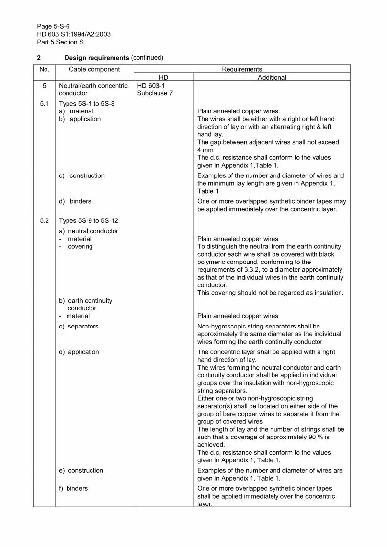
Page 5-S-6 HD 603 S1:1994/A2:2003 Part 5 Section S
2 Design requirements (continued)
Requirements No. Cable component HD Additional
5 Neutral/earth concentric conductor
HD 603-1 Subclause 7
5.1 Types 5S-1 to 5S-8 a) material b) application
Plain annealed copper wires. The wires shall be either with a right or left hand direction of lay or with an alternating right & left hand lay. The gap between adjacent wires shall not exceed 4 mm The d.c. resistance shall conform to the values given in Appendix 1,Table 1.
c) construction Examples of the number and diameter of wires and the minimum lay length are given in Appendix 1, Table 1.
d) binders One or more overlapped synthetic binder tapes may be applied immediately over the concentric layer.
5.2 Types 5S-9 to 5S-12 a) neutral conductor - material - covering
Plain annealed copper wires To distinguish the neutral from the earth continuity conductor each wire shall be covered with black polymeric compound, conforming to the requirements of 3.3.2, to a diameter approximately as that of the individual wires in the earth continuity conductor. This covering should not be regarded as insulation.
b) earth continuity conductor - material
Plain annealed copper wires
c) separators Non-hygroscopic string separators shall be approximately the same diameter as the individual wires forming the earth continuity conductor
d) application The concentric layer shall be applied with a right hand direction of lay. The wires forming the neutral conductor and earth continuity conductor shall be applied in individual groups over the insulation with non-hygroscopic string separators. Either one or two non-hygroscopic string separator(s) shall be located on either side of the group of bare copper wires to separate it from the group of covered wires The length of lay and the number of strings shall be such that a coverage of approximately 90 % is achieved. The d.c. resistance shall conform to the values given in Appendix 1, Table 1.
e) construction Examples of the number and diameter of wires are given in Appendix 1, Table 1.
f) binders One or more overlapped synthetic binder tapes shall be applied immediately over the concentric layer.

Page 5-S-7 HD 603 S1:1994/A2:2003
Part 5 Section S
2 Design requirements (concluded)
Requirements No. Cable component HD Additional
6 Oversheath 6.1 Material
6.1.1 Types 5S-1 to 5S-4 and 5S-9 to 5S-12
HD 603-1, Subclause 5.8 Table 4A, DMV 23
6.1.2 Colour Black Colours other than black may be provided by agreement between the manufacturer and the purchaser, subject to their suitability for the particular conditions under which the cables are to be used.
6.3 Thickness HD 603-1 Subclause 5.8.3
Appendix 1, Table 1
7 Marking Appendix 2 8 Sealing Before dispatch, the manufacturer shall cap the
ends of the cable in order to form a seal to prevent the ingress of water during transportation and storage.
3 Test requirements
1 Routine tests
No. Tests Requirements * Test methods
1 Conductor resistance: - phase - combine neutral/earth (5S-1 to 5S-8) - neutral (5S-9 to 5S-12) - earth continuity (5S-9 to 5S-12)
Appendix 1, Table 1
HD 605 - Subclause 3.2.1
2 Voltage test on complete cable: - Test voltage - Duration - Acceptance criteria For cable types 5S-9 to 5S-12, an additional voltage test shall be applied between the bare earth continuity wires and the covered neutral wires in the concentric layer: - Test voltage - Duration - Acceptance criteria
3,5 kV a.c. 5 min No failure 500 V d.c. 1 min No failure
HD 605 - Subclause 3.2.1
3 Spark test on insulation No failure HD 605, Subclause 3.6.1
4 Spark test on oversheath No failure HD 605, Subclause 3.6.1
5 Marking Appendix 2 Visual examination
* According to Section 2 Design requirements unless stated otherwise.

Page 5-S-8 HD 603 S1:1994/A2:2003 Part 5 Section S
3 Test requirements (continued)
2 Sample tests
No. Tests Requirements * Test methods
1 Phase conductor material and construction
Clause 1 HD 605 - Subclause 2.3.1.2 and by visual examination
2 Concentric neutral/earth conductor material and construction
Clause 5 Visual examination and measurement
3 Insulation:
- application Clause 2 Visual examination
- thickness Appendix 1, Table 1 HD 605, Subclause 2.1.1
- colour Subclause 2.3 HD 605, Subclause 2.5.4
4 Oversheath:
- application Clause 6 Visual examination
- thickness Appendix 1, Table 1 HD 605, Subclause 2.1.2
5 Test under fire conditions
5.1 Flame propagation on single cable
EN 50265-2-1 EN 50265-2-1
5.2 Smoke emission (types 5S-5 to 5S-8 only)
Light transmittance shall not fall below 70 %
EN 50268
* According to Section 2 Design requirements unless stated otherwise.
3 Type tests
No. Tests Requirements * Test methods
1 Insulation: Clause 1 HD 605, Subclause 2.3.1.2 and by visual examination
- material HD 603-1 Table 2A DIX3
EN 60811-1-1, Subclause 9.1 EN 60811-1-2, Subclause 8.1.3 EN 60811-2-1, Clause 9 EN 60811-1-3, Clause 10 and Subclause 9.2
- shrinkage Shall not exceed 4 % EN 60811-1-3
2 Neutral covering material Type 5S-9 to 5S-12
Tensile strength not less than 4 Nmm2
Elongation at break not less than 50 %
EN 60811-1-1
* According to Section 2 Design requirements unless stated otherwise.

Page 5-S-9 HD 603 S1:1994/A2:2003
Part 5 Section S
3 Test requirements (concluded) 3 Type tests (concluded)
No. Tests Requirements * Test methods
3 Type 5S-1 to 5S-4 and 5S-9 to 5S-12 cables
3.1 Oversheath material HD 603-1 Table 4A - DMV 23
EN 60811-1-1, Subclause 9.2 EN 60811-1-2, Subclause 8.1.3 EN 60811-3-2, Subclause 8.2 EN 60811-3-1, Subclause 8.2 EN 60811-1-4, Clause 8
3.2 Compatibility test on complete cable
HD 603-1 Table 2A - DIX 3 and Table 4A - DMV 23
HD 605, Subclause 2.4.12.2
4 Type 5S-5 to 5S-8 (low smoke cables only)
4.1 Corrosive and acid gas (on all non-metallic components)
HCl level not greater than 0,5 %
EN 50267-2-1
4.2 Oversheath:
- material Appendix 3 Appendix 3
- shrinkage Shall not exceed 4 % Appendix 4
- insulation resistance The value of K shall not be less than 0,003 5 MΩ.km.
HD 605, Subclause 3.3.4
4.3 Compatibility test on complete cable
HD 603-1 Table 2A - DIX 3 and Appendix 3
HD 605, Subclause 2.4.12.2
4.4 Flame propagation on multiple cables
Shall conform to the requirements of Category C.
EN 50266-2-4
4 Smoke emission The value of light transmittance shall not fall below 70 %.
EN 50268
4.6 Abrasion test The oversheath shall have no cracks or splits in the external and internal surfaces without visible magnification.
HD 605, Subclause 2.4.5
* According to Section 2 Design requirements unless stated otherwise.

Page 5-S-10 HD 603 S1:1994/A2:2003 Part 5 Section S
4 Appendices
1 Table 1 - 0,6/1 kV XLPE insulated and PVC sheathed cables
Table 1a - Type 5S-1 Single phase copper conductor with combined concentric copper neutral/earth conductor
Form of phase conductors Circular or compacted circular stranded Nominal cross-sectional area of phase conductor (mm2) 4 16 25 Minimum average thickness of insulation (mm) 0,7 0,7 0,9 Minimum thickness of insulation at any point (mm) 0,53 0,53 0,71 Concentric neutral/earth conductor, e.g. approximate number of wires 15 19 25 approximate diameter of wires (mm) 0,67 1,04 1,13 approximate length of lay (mm) 65 110 135
Minimum average thickness of oversheath (mm) 1,4 1,4 1,4 Minimum thickness of oversheath at any point (mm) 1,09 1,09 1,09 Approximate overall diameter (mm) 8,5 11,8 13,7 Maximum d.c. resistance per km of cable at 20 °C: a) phase conductor (Ω) 4,61 1,15 0,727 b) concentric neutral/earth conductor (Ω) 4,8 1,2 0,76
Table 1b - Type 5S-2 Single phase aluminium conductor with combined concentric copper neutral/earth conductor
Form of phase conductors Circular solid Nominal cross-sectional area of phase conductor (mm²) 25 35
Minimum average thickness of insulation (mm) 0,9 0,9 Minimum thickness of insulation at any point (mm) 0,71 0,71 Concentric neutral/earth conductor, e.g. approximate number of wires 27 25 approximate diameter of wires (mm) 0,85 1,04 approximate length of lay (mm) 120 140 Minimum average thickness of oversheath (mm) 1,4 1,4 Minimum thickness of oversheath at any point (mm) 1,09 1,09 Approximate overall diameter (mm) 12,3 13,7 Maximum d.c. resistance per km of cable at 20 °C: a) phase conductor (Ω) 1,2 0,868 b) concentric neutral/earth conductor (Ω) 1,3 0,91
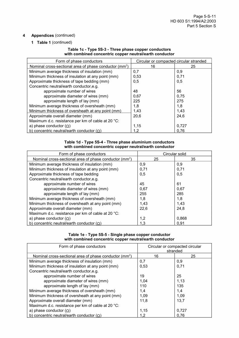
Page 5-S-11 HD 603 S1:1994/A2:2003
Part 5 Section S
4 Appendices (continued)
1 Table 1 (continued)
Table 1c - Type 5S-3 - Three phase copper conductors with combined concentric copper neutral/earth conductor
Form of phase conductors Circular or compacted circular stranded Nominal cross-sectional area of phase conductor (mm2) 16 25 Minimum average thickness of insulation (mm) 0,7 0,9 Minimum thickness of insulation at any point (mm) 0,53 0,71 Approximate thickness of tape bedding (mm) 0,5 0,5 Concentric neutral/earth conductor,e.g. approximate number of wires 48 56 approximate diameter of wires (mm) 0,67 0,75 approximate length of lay (mm) 225 275 Minimum average thickness of oversheath (mm) 1,8 1,8 Minimum thickness of oversheath at any point (mm) 1,43 1,43 Approximate overall diameter (mm) 20,6 24,6 Maximum d.c. resistance per km of cable at 20 °C: a) phase conductor (Ω) 1,15 0,727 b) concentric neutral/earth conductor (Ω) 1,2 0,76
Table 1d - Type 5S-4 - Three phase aluminium conductors with combined concentric copper neutral/earth conductor
Form of phase conductors Circular solid Nominal cross-sectional area of phase conductor (mm2) 25 35
Minimum average thickness of insulation (mm) 0,9 0,9 Minimum thickness of insulation at any point (mm) 0,71 0,71 Approximate thickness of tape bedding 0,5 0,5 Concentric neutral/earth conductor,e.g. approximate number of wires 45 61 approximate diameter of wires (mm) 0,67 0,67 approximate length of lay (mm) 255 285 Minimum average thickness of oversheath (mm) 1,8 1,8 Minimum thickness of oversheath at any point (mm) 1,43 1,43 Approximate overall diameter (mm) 22,6 24,8 Maximum d.c. resistance per km of cable at 20 °C: a) phase conductor (Ω) 1,2 0,868 b) concentric neutral/earth conductor (Ω) 1,3 0,91
Table 1e - Type 5S-5 - Single phase copper conductor with combined concentric copper neutral/earth conductor
Form of phase conductors Circular or compacted circular stranded
Nominal cross-sectional area of phase conductor (mm2) 16 25 Minimum average thickness of insulation (mm) 0,7 0,9 Minimum thickness of insulation at any point (mm) 0,53 0,71 Concentric neutral/earth conductor,e.g. approximate number of wires 19 25 approximate diameter of wires (mm) 1,04 1,13 approximate length of lay (mm) 110 135 Minimum average thickness of oversheath (mm) 1,4 1,4 Minimum thickness of oversheath at any point (mm) 1,09 1,09 Approximate overall diameter (mm) 11,8 13,7 Maximum d.c. resistance per km of cable at 20 °C: a) phase conductor (Ω) 1,15 0,727 b) concentric neutral/earth conductor (Ω) 1,2 0,76
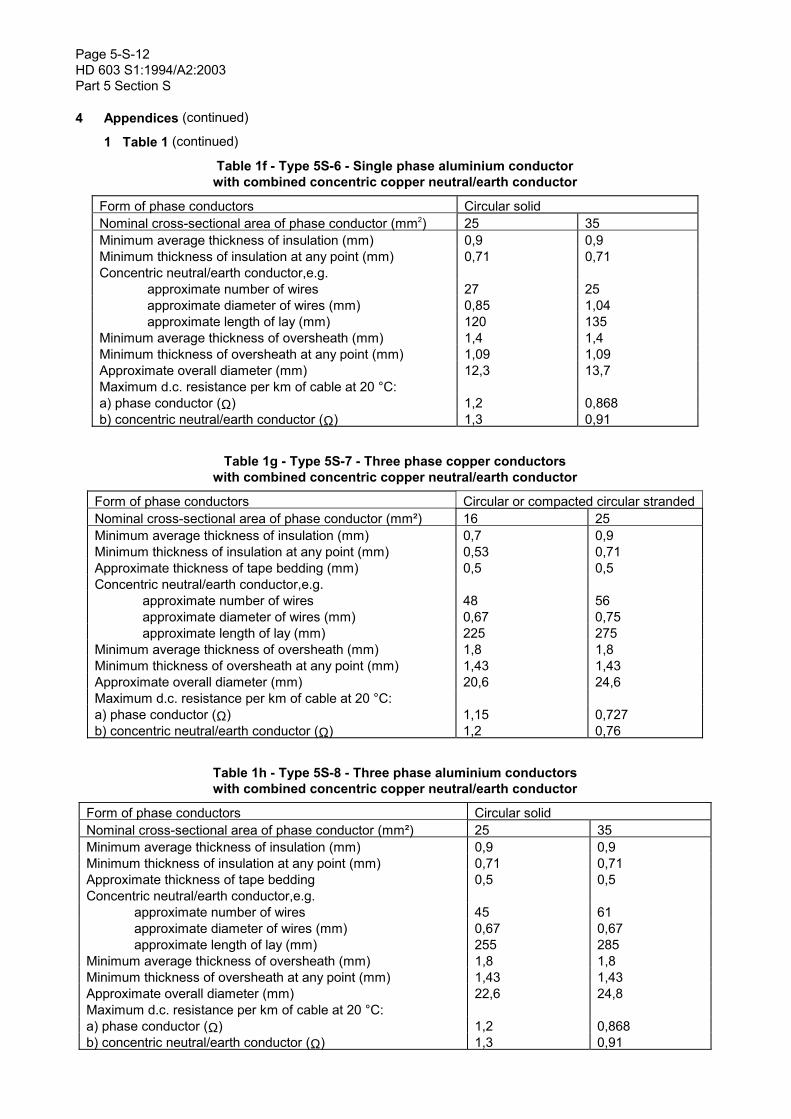
Page 5-S-12 HD 603 S1:1994/A2:2003 Part 5 Section S
4 Appendices (continued)
1 Table 1 (continued)
Table 1f - Type 5S-6 - Single phase aluminium conductor with combined concentric copper neutral/earth conductor
Form of phase conductors Circular solid Nominal cross-sectional area of phase conductor (mm2) 25 35 Minimum average thickness of insulation (mm) 0,9 0,9 Minimum thickness of insulation at any point (mm) 0,71 0,71 Concentric neutral/earth conductor,e.g. approximate number of wires 27 25 approximate diameter of wires (mm) 0,85 1,04 approximate length of lay (mm) 120 135 Minimum average thickness of oversheath (mm) 1,4 1,4 Minimum thickness of oversheath at any point (mm) 1,09 1,09 Approximate overall diameter (mm) 12,3 13,7 Maximum d.c. resistance per km of cable at 20 °C: a) phase conductor (Ω) 1,2 0,868 b) concentric neutral/earth conductor (Ω) 1,3 0,91
Table 1g - Type 5S-7 - Three phase copper conductors with combined concentric copper neutral/earth conductor
Form of phase conductors Circular or compacted circular stranded Nominal cross-sectional area of phase conductor (mm²) 16 25 Minimum average thickness of insulation (mm) 0,7 0,9 Minimum thickness of insulation at any point (mm) 0,53 0,71 Approximate thickness of tape bedding (mm) 0,5 0,5 Concentric neutral/earth conductor,e.g. approximate number of wires 48 56 approximate diameter of wires (mm) 0,67 0,75 approximate length of lay (mm) 225 275 Minimum average thickness of oversheath (mm) 1,8 1,8 Minimum thickness of oversheath at any point (mm) 1,43 1,43 Approximate overall diameter (mm) 20,6 24,6 Maximum d.c. resistance per km of cable at 20 °C: a) phase conductor (Ω) 1,15 0,727 b) concentric neutral/earth conductor (Ω) 1,2 0,76
Table 1h - Type 5S-8 - Three phase aluminium conductors with combined concentric copper neutral/earth conductor
Form of phase conductors Circular solid Nominal cross-sectional area of phase conductor (mm²) 25 35 Minimum average thickness of insulation (mm) 0,9 0,9 Minimum thickness of insulation at any point (mm) 0,71 0,71 Approximate thickness of tape bedding 0,5 0,5 Concentric neutral/earth conductor,e.g. approximate number of wires 45 61 approximate diameter of wires (mm) 0,67 0,67 approximate length of lay (mm) 255 285 Minimum average thickness of oversheath (mm) 1,8 1,8 Minimum thickness of oversheath at any point (mm) 1,43 1,43 Approximate overall diameter (mm) 22,6 24,8 Maximum d.c. resistance per km of cable at 20 °C: a) phase conductor (Ω) 1,2 0,868 b) concentric neutral/earth conductor (Ω) 1,3 0,91
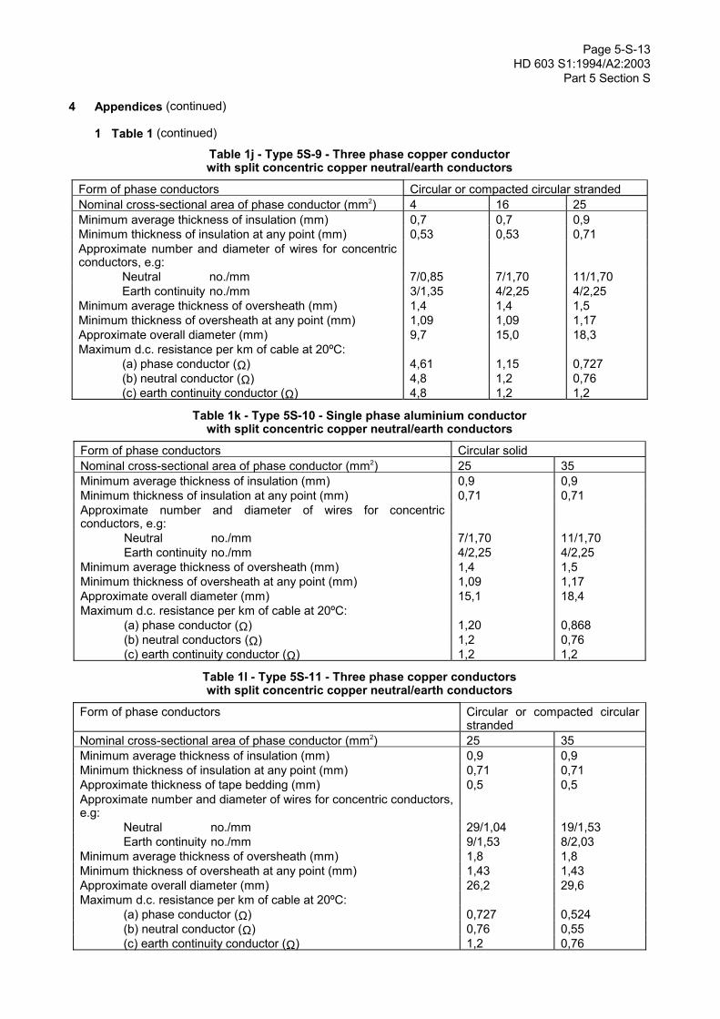
Page 5-S-13 HD 603 S1:1994/A2:2003
Part 5 Section S
4 Appendices (continued) 1 Table 1 (continued)
Table 1j - Type 5S-9 - Three phase copper conductor with split concentric copper neutral/earth conductors
Form of phase conductors Circular or compacted circular stranded Nominal cross-sectional area of phase conductor (mm2) 4 16 25 Minimum average thickness of insulation (mm) 0,7 0,7 0,9 Minimum thickness of insulation at any point (mm) 0,53 0,53 0,71 Approximate number and diameter of wires for concentric conductors, e.g:
Neutral no./mm 7/0,85 7/1,70 11/1,70 Earth continuity no./mm 3/1,35 4/2,25 4/2,25 Minimum average thickness of oversheath (mm) 1,4 1,4 1,5 Minimum thickness of oversheath at any point (mm) 1,09 1,09 1,17 Approximate overall diameter (mm) 9,7 15,0 18,3 Maximum d.c. resistance per km of cable at 20ºC: (a) phase conductor (Ω) 4,61 1,15 0,727 (b) neutral conductor (Ω) 4,8 1,2 0,76 (c) earth continuity conductor (Ω) 4,8 1,2 1,2
Table 1k - Type 5S-10 - Single phase aluminium conductor with split concentric copper neutral/earth conductors
Form of phase conductors Circular solid Nominal cross-sectional area of phase conductor (mm2) 25 35 Minimum average thickness of insulation (mm) 0,9 0,9 Minimum thickness of insulation at any point (mm) 0,71 0,71 Approximate number and diameter of wires for concentric conductors, e.g:
Neutral no./mm 7/1,70 11/1,70 Earth continuity no./mm 4/2,25 4/2,25 Minimum average thickness of oversheath (mm) 1,4 1,5 Minimum thickness of oversheath at any point (mm) 1,09 1,17 Approximate overall diameter (mm) 15,1 18,4 Maximum d.c. resistance per km of cable at 20ºC: (a) phase conductor (Ω) 1,20 0,868 (b) neutral conductors (Ω) 1,2 0,76 (c) earth continuity conductor (Ω) 1,2 1,2
Table 1l - Type 5S-11 - Three phase copper conductors with split concentric copper neutral/earth conductors
Form of phase conductors Circular or compacted circular stranded
Nominal cross-sectional area of phase conductor (mm2) 25 35 Minimum average thickness of insulation (mm) 0,9 0,9 Minimum thickness of insulation at any point (mm) 0,71 0,71 Approximate thickness of tape bedding (mm) 0,5 0,5 Approximate number and diameter of wires for concentric conductors, e.g:
Neutral no./mm 29/1,04 19/1,53 Earth continuity no./mm 9/1,53 8/2,03 Minimum average thickness of oversheath (mm) 1,8 1,8 Minimum thickness of oversheath at any point (mm) 1,43 1,43 Approximate overall diameter (mm) 26,2 29,6 Maximum d.c. resistance per km of cable at 20ºC: (a) phase conductor (Ω) 0,727 0,524 (b) neutral conductor (Ω) 0,76 0,55 (c) earth continuity conductor (Ω) 1,2 0,76

Page 5-S-14 HD 603 S1:1994/A2:2003 Part 5 Section S
4 Appendices (continued)
1 Table 1 (concluded)
Table 1m - Type 5S-12 Three phase aluminium conductors with split concentric copper neutral/earth conductors
Form of phase conductors Circular solid Nominal cross-sectional area of phase conductor (mm2) 25 35
Minimum average thickness of insulation (mm) 0,9 0,9 Minimum thickness of insulation at any point (mm) 0,71 0,71 Approximate thickness of tape bedding (mm) 0,5 0,5 Approximate number and diameter of wires for concentric conductors, e.g:
Neutral no./mm 28/0,85 29/1,04 Earth continuity no./mm 11/1,35 9/1,53 Minimum average thickness of oversheath (mm) 1,8 1,8 Minimum thickness of oversheath at any point (mm) 1,43 1,43 Approximate overall diameter (mm) 24,0 26,5 Maximum d.c. resistance per km of cable at 20ºC: (a) phase conductor (Ω) 1,2 0,868 (b) neutral conductor (Ω) 1,2 0,76 (c) earth continuity conductor (Ω) 1,2 1,20
2 Marking 1 External marking The external surface of all cables conforming to this standard shall be legibly marked with the following elements. Element Example of marking a) Electric cable: ELECTRIC CABLE b) Voltage designation: 600/1 000 V c) Standard number: HD 603-5S d) Manufacturers identification XYZ e) Number of cores, type andshall indicatye nominal area of phase conductors, e.g.
1) 3 x 25 AL/CU shall indicate a three-core cable with a 25 mm2 aluminium phase conductors having a copper concentric neutral/earth conductor. 2) 1 x 25 shall indicate a single-core cable having a 25 mm2 copper phase conductor and a copper concentric neutral/earth conductor.
The marking of the elements a) to d) shall be by embossing or indenting on the oversheath. For cables with tabulated approximate overall diameters greater than 15 mm, elements a), b) and c) shall appear, in any sequence that is deemed neither to confuse nor conflict, on two or more primary lines along the axis of the cable, approximately equally spaced around the circumference of the cable. Elements d) and e) shall appear, together or separately, in any sequence that is deemed neither to confuse nor conflict, on either one of the primary lines, or on a secondary line or lines.

Page 5-S-15 HD 603 S1:1994/A2:2003
Part 5 Section S
4 Appendices (continued) 2 Marking (continued) For cables with tabulated approximate overall diameters of 15 mm or less, the elements shall be arranged as for cables of greater than 15 mm diameter, except that the marking for elements a), b) and c) shall appear on one or more primary lines. The letters and figures shall consist of upright block characters. The characters shall have a minimum height of 3 mm. The distance between the end of one element of marking and the beginning of the next identical element shall be not greater than 550 mm for elements a), b) and c), and not greater than 1 100 mm for elements d) and e). 2 Identification of year of manufacture A means of identifying the year of manufacture of the cable shall be provided throughout the length of the cable, either internally or by marking on the surface of the cable. If the identification mark is internal, the distance between the end of one mark and the beginning of the next mark shall be not greater than 550 mm. NOTE An identification thread may be used as an alternative to internal marking. If the identification is by marking on the surface it shall conform to the requirements given in 1d) and e) in respect of the maximum distance between marks. 3 The mark of an approval organisation If the mark of an approval organisation is used, it shall be provided throughout the length of the cable, either as a mark on the surface of the cable, or as an identification thread, as specified by the approval organisation. If the mark is applied to the cable, it shall be on the surface in the form of the symbol(s) specified by the approval organisation, and shall conform to the requirements given in 1d) and e) in respect of the maximum distance between marks. 4 Additional marking Where additional marking is made, it shall be throughout the length of the cable, and on the external surface of the cable, or by means of a tape or thread within the cable, or by a combination of these methods. If the additional marking is applied to the surface of the cable it shall not render illegible the marking specified in 1 to 3. The additional marking, however made, shall be repeated at intervals not exceeding 1 100 mm. 5 End markings The end of each drum length of three-phase cable at which the sequence of core colours is clockwise shall be marked red. The other end shall be marked green.
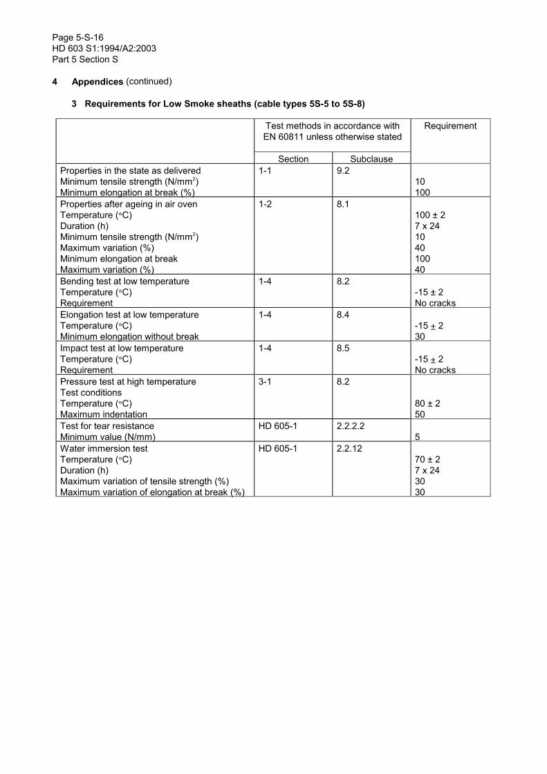
Page 5-S-16 HD 603 S1:1994/A2:2003 Part 5 Section S
4 Appendices (continued)
3 Requirements for Low Smoke sheaths (cable types 5S-5 to 5S-8)
Test methods in accordance with EN 60811 unless otherwise stated
Requirement
Section Subclause Properties in the state as delivered 1-1 9.2 Minimum tensile strength (N/mm2) 10 Minimum elongation at break (%) 100 Properties after ageing in air oven 1-2 8.1 Temperature (°C) 100 ± 2 Duration (h) 7 x 24 Minimum tensile strength (N/mm2) 10 Maximum variation (%) 40 Minimum elongation at break 100 Maximum variation (%) 40 Bending test at low temperature 1-4 8.2 Temperature (°C) -15 ± 2 Requirement No cracks Elongation test at low temperature 1-4 8.4 Temperature (°C) -15 ± 2 Minimum elongation without break 30 Impact test at low temperature 1-4 8.5 Temperature (°C) -15 ± 2 Requirement No cracks Pressure test at high temperature 3-1 8.2 Test conditions Temperature (°C) 80 ± 2 Maximum indentation 50 Test for tear resistance HD 605-1 2.2.2.2 Minimum value (N/mm) 5 Water immersion test HD 605-1 2.2.12 Temperature (°C) 70 ± 2 Duration (h) 7 x 24 Maximum variation of tensile strength (%) 30 Maximum variation of elongation at break (%) 30

Page 5-S-17 HD 603 S1:1994/A2:2003
Part 5 Section S
4 Appendices (concluded)
4 Shrinkage test for Low Smoke sheaths (cable types 5S-5 to 5S-8)
4.1 General This test shall be carried out to determine the shrinkage of sheath during heat treatment. The test shall be carried out in accordance with BS EN 60811-1-3 modified in accordance with 4.2 to 4.5.
4.2 Selection of samples Take one sample, about 0,3 m in length, of each cable to be tested at least 0,5 m away from the end of the cable length. 4.3 Preparation of test piece Within an interval of not more than 5 min from the time of cutting the sample, mark a test length of 200 mm ± 5 mm on the middle part of the test piece. Measure the distance between the marks to an accuracy of 0,5 mm. Prepare the test piece by removing the sheath from both ends of the sample up to positions between 2 mm and 5 mm away from the marks. Bind the CNE wires at both ends of the sample. 4.4 Procedure Perform the test in an air oven as described in BS EN 60811-1-3. Support the test piece by means of a freshly prepared talc bath. The combined volume of test apparatus and test piece shall not exceed 10 % of the volume of the oven. Preheat the oven with the test apparatus in place for a minimum of 2 h at 80 °C before the test piece is introduced. Support the test piece horizontally on the surface of the talc bath. Ensure that there is sufficient depth of talc so that, the test piece does not touch the bottom of the bath. Spread the talc evenly, without compacting it, at the start of the test, so as to permit free movement of the sheath. Introduce the test piece into the test oven, and maintain it at a temperature of (80 ± 2) °C for 4 h. At the end of this period, remove the apparatus with the test piece in place, and allow it to cool ambient temperature. Re-measure the distance between the two marks on the test piece to the nearest 0,5 mm. 4.5 Evaluation of results Calculate the difference in the distance between the marks before the heat treatment and after the heating and cooling, and record the shrinkage as a percentage of the distance between the marks before the treatment.

Page 5-S-18 HD 603 S1:1994/A2:2003 Part 5 Section S
BLANK PAGE

Page 6-A-0 HD 603 S1:1994/A2:2003
Part 6 Section A
SECTION 6-A - CABLES WITH BRAIDED (TYPE 6A-1) OR HELICALLY APPLIED (TYPE 6A-2) ARMOUR
Replace Section 6-A
by the following A2 referred new Section 6-A:


Page 6-A-1 HD 603 S1:1994/A2:2003
Part 6 Section A
SECTION 6-A - CABLES WITH BRAIDED (TYPE 6A-1) OR HELICALLY APPLIED (TYPE 6A-2) ARMOUR

Page 6-A-2 HD 603 S1:1994/A2:2003 Part 6 Section A
CONTENTS
1 General--------------------------------------------------------------------------------------------------------------------------- 3
2 Design requirements---------------------------------------------------------------------------------------------------------- 4
1 Conductor ------------------------------------------------------------------------------------------------------------- 4 1.1 Material 1.2 Main conductors 1.3 Mechanical properties of aluminium conductors 1.4 Auxiliary conductors 1.5 Conductor resistance 1.6 Permissible conductor types
2 Insulation -------------------------------------------------------------------------------------------------------------- 4 2.1 Material 2.2 Insulation thickness 2.3 Core identification
3 Assembly of cores and fillers ------------------------------------------------------------------------------------- 5 3.1 Assembly of cores 3.2 Fillers
4 Inner covering -------------------------------------------------------------------------------------------------------- 5 4.1 Thickness
5 Innersheath ----------------------------------------------------------------------------------------------------------- 5 5.1 Material 5.2 Thickness 5.3 Colour
6 Metallic layers -------------------------------------------------------------------------------------------------------- 6 6.1 Steel wire braid armour and protective earth conductor 6.2 Helically applied armour and protective earth conductor
7 Oversheath ----------------------------------------------------------------------------------------------------------- 6 7.1 Material 7.2 Thickness 7.3 Colour
8 Marking ---------------------------------------------------------------------------------------------------------------- 7 8.1 Indication of origin 8.2 Year of manufacture 8.3 Code designation 8.4 Continuity of marks 8.5 Durability 8.6 Legibility 8.7 Meter marking
9. Code designation---------------------------------------------------------------------------------------------------- 7
3 Test requirements ------------------------------------------------------------------------------------------------------------- 7 1 Routine tests ------------------------------------------------------------------------------------------------- 7 2 Sample tests-------------------------------------------------------------------------------------------------- 8 3 Type tests, electrical---------------------------------------------------------------------------------------11 4 Type tests, non-electrical---------------------------------------------------------------------------------12
4 Appendix (tables and Guide to use)--------------------------------------------------------------------------------------14

Page 6-A-3 HD 603 S1:1994/A2:2003
Part 6 Section A
REFERENCES
References are made in Section 6-A of HD 603, to other parts of this HD and to other Harmonization Documents, European and International Standards as follows:
HD 383 Conductors of insulated cables First supplement: Guide to the dimensional limits of circular conductors (endorsing IEC 60228 and 60228A)
HD 605 Electric cables Additional test methods
EN 50265 (series) Common test methods for cables under fire conditions Test for resistance to vertical flame propagation for a single insulated conductor or cable
EN 60811 (series) Insulating and sheathing materials of electric cables Common test methods
In all cases reference to another HD or International Standard implies the latest edition of that document.
1 General
This standard specifies the construction, dimensions and test requirements of power cables with XLPE-insulation, with combined armour/protective earth conductor and PVC sheath for rated voltage (U) of 1 kV for fixed installations 1) (Cables with braided (type 6A-1) or helically applied (type 6A-2) armour).
The cables may be provided with auxiliary cores.
(a) Insulating material
The insulation covered by this standard shall consist of cross-linked polyethylene and correspond to Table 2A, type DIX3 of HD 603-1.
(b) Rated voltage
0,6/1 kV
Definitions: see HD 603-1, Subclause 2.3
(c) Highest rated temperatures for the insulating compound
Normal operation 90 °C
(d) Sheathing material
Shall be suitable for the maximum rated conductor temperature. It shall consist of PVC and correspond to Table 4A, type DMV15 of HD 603-1.
(e) Test requirements
Type test (symbol T): Validity of a type test is 5 years.
1) The cables in this section are service cables; an armoured main cable is not included in this HD. Instead of an armoured cable, the cable with concentric conductor as mentioned in Table 1 of Part 3, Section 1, can be applied. That cable type will also give some mechanical protection.
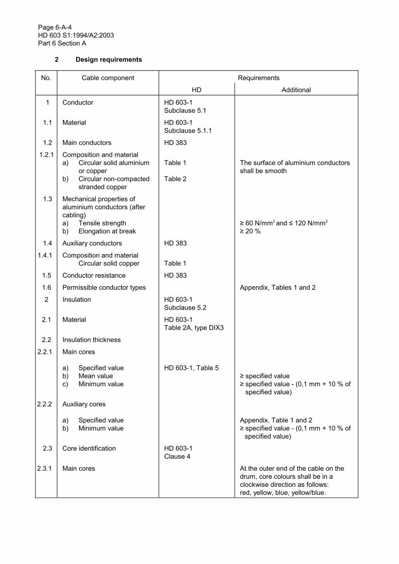
Page 6-A-4 HD 603 S1:1994/A2:2003 Part 6 Section A
2 Design requirements
No. Cable component Requirements
HD Additional
1 Conductor HD 603-1 Subclause 5.1
1.1 Material HD 603-1 Subclause 5.1.1
1.2 Main conductors HD 383
1.2.1 Composition and material a) Circular solid aluminium or copper b) Circular non-compacted stranded copper
Table 1 Table 2
The surface of aluminium conductors shall be smooth
1.3 Mechanical properties of aluminium conductors (after cabling) a) Tensile strength b) Elongation at break
≥ 60 N/mm2 and ≤ 120 N/mm2 ≥ 20 %
1.4 Auxiliary conductors HD 383
1.4.1 Composition and material Circular solid copper
Table 1
1.5 Conductor resistance HD 383
1.6 Permissible conductor types Appendix, Tables 1 and 2
2 Insulation HD 603-1 Subclause 5.2
2.1 Material HD 603-1 Table 2A, type DIX3
2.2 Insulation thickness
2.2.1 Main cores a) Specified value b) Mean value c) Minimum value
HD 603-1, Table 5
≥ specified value ≥ specified value - (0,1 mm + 10 % of specified value)
2.2.2 Auxiliary cores a) Specified value b) Minimum value
Appendix, Table 1 and 2 ≥ specified value - (0,1 mm + 10 % of specified value)
2.3 Core identification HD 603-1 Clause 4
2.3.1 Main cores At the outer end of the cable on the drum, core colours shall be in a clockwise direction as follows: red, yellow, blue, yellow/blue.
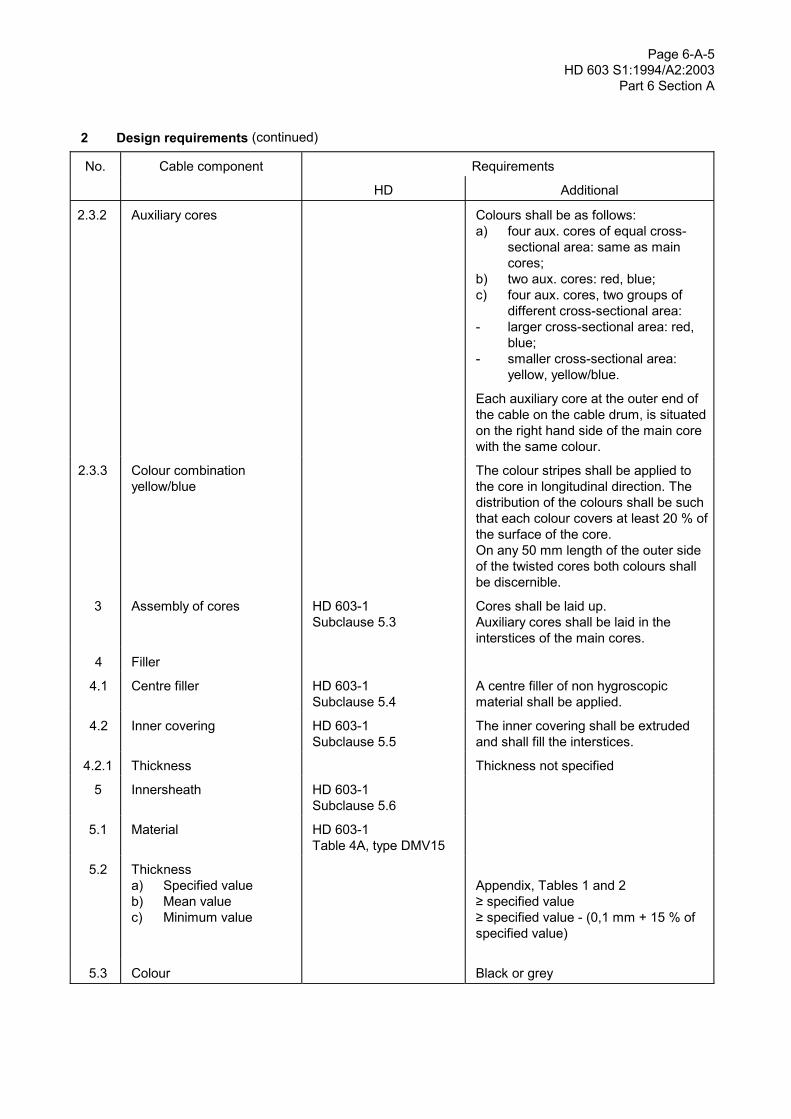
Page 6-A-5 HD 603 S1:1994/A2:2003
Part 6 Section A
2 Design requirements (continued)
No. Cable component Requirements
HD Additional
2.3.2 Auxiliary cores Colours shall be as follows: a) four aux. cores of equal cross- sectional area: same as main cores; b) two aux. cores: red, blue; c) four aux. cores, two groups of different cross-sectional area: - larger cross-sectional area: red, blue; - smaller cross-sectional area: yellow, yellow/blue.
Each auxiliary core at the outer end of the cable on the cable drum, is situated on the right hand side of the main core with the same colour.
2.3.3 Colour combination yellow/blue
The colour stripes shall be applied to the core in longitudinal direction. The distribution of the colours shall be such that each colour covers at least 20 % of the surface of the core. On any 50 mm length of the outer side of the twisted cores both colours shall be discernible.
3 Assembly of cores HD 603-1 Subclause 5.3
Cores shall be laid up. Auxiliary cores shall be laid in the interstices of the main cores.
4 Filler
4.1 Centre filler HD 603-1 Subclause 5.4
A centre filler of non hygroscopic material shall be applied.
4.2 Inner covering HD 603-1 Subclause 5.5
The inner covering shall be extruded and shall fill the interstices.
4.2.1 Thickness Thickness not specified
5 Innersheath HD 603-1 Subclause 5.6
5.1 Material HD 603-1 Table 4A, type DMV15
5.2 Thickness a) Specified value b) Mean value c) Minimum value
Appendix, Tables 1 and 2 ≥ specified value ≥ specified value - (0,1 mm + 15 % of specified value)
5.3 Colour Black or grey

Page 6-A-6 HD 603 S1:1994/A2:2003 Part 6 Section A
2 Design requirements (continued)
No. Cable component Requirements
HD Additional
6 Metallic layers
6.1 For cable type 6A-1 (with braid armour and protective earth (PE-conductor)
6.1 a) The steel wire braid armour/PE-conductor shall be applied to the innersheath. It shall consist of braiding of galvanised steel wires with one or more continuous flat braided conductors of tinned copper wires underneath. The nominal diameter of the steel wires shall be 0,3 mm with a minimum of 0,27 mm. The nominal diameter of the copper wires shall be 0,25 mm with a minimum of 0,20 mm. The percentage of coverage of the innersheath by the steel wire braiding shall be ≥ 80 %. The nominal copper equivalent cross-sectional area of the steel wire braid armour/PE-conductor is given in Table 1, the total cross-sectional area of the flat braided copper conductor(s) shall be at last 80 % of this value. In case of more than one flat braided copper conductor, the cross-sectional area of each conductor shall be at least 1 mm2 .
The resistance of the steel wire braid armour/PE-conductor shall comply with the value given in Table 1. 6.1 b) Additionally the resistance of the steel wire braid armour/PE-conductor measured on a length of 20 m with the current source at one side connected to 5 % of the steel wires shall not exceed 2,5 % of the specified maximum value in Table 1.
6.2 For cable type 6A-2 (with helically applied armour/PE-conductor)
6.2 a) The combined armour/PE-conductor shall be applied helically to the innersheath and shall be manufactured of galvanised steel wires and annealed copper wires with a counter helix of copper tape. The minimum diameter of the steel and copper wires shall be 1,0 mm. The total covering or the innersheath by the steel and copper wires shall be ≥ 80 %. The gap between adjacent wires shall be ≤ 2 mm. The nominal copper equivalent cross-sectional area of the combined armour/PE-conductor is given in Table 2, the total cross-sectional area of the copper wires shall be at least 60 % of this value. The resistance of the combined armour/PE-conductor shall comply with the value given in Table 2. 6.2 b) Additionally the resistance of the combined armour/PE-conductor measured on a length of 20 m with the current source at one side connected to 2 steel wires shall not exceed 2,5 % of the specified maximum value in Table 2.
7 Oversheath HD 603-1 Subclause 5.8
7.1 Material HD 603-1 Table 4A, type DMV15

Page 6-A-7 HD 603 S1:1994/A2:2003
Part 6 Section A
2 Design requirements (concluded)
No. Cable component Requirements
HD Additional
7.2 Thickness a) Specified value b) Mean value c) Minimum value
Appendix, Tables 1 and 2 ≥ specified value ≥ specified value - (0,3 mm + 15 % of specified value)
7.3 Colour Grey
8 Marking HD 603-1 Clause 3
Marking shall be applied by embossing or printing.
8.1 Indication of origin on the oversheath
Manufacturers name or trademark
8.2 Year of manufacture To be indicated on the oversheath
8.3 Code designation To be indicated on the oversheath
8.4 Continuity of marks Distance between the end of one set of marks and the beginning of the next ≤ 0,5 m
8.5 Durability HD 603-1 Subclause 3.3
8.6 Legibility HD 603-1 Subclause 3.4
8.7 Meter marking - Either by a tape in the cable - Or by embossing or printing on the oversheath
9 Code designation Examples *:
For cable with steel wire braid armour/PE-conductor (type 6A-1)
a) cables without auxiliary cores VO-YMvKas 0,6/1 kV 4x6rm NEN 3616 b) cables with auxiliary cores VO-YMvKhas 0,6/1 kV 4x10rm+ 4x2,5 NEN 3616
For cable with helically applied armour/PE-conductor (type 6A-2)
a) cables without auxiliary cores VG-YMvKas 0,6/1 kV 4x16Alrm NEN 3616 b) cables with auxiliary cores VG-YMvKhas 0,6/1 kV 4x25rs + 4x2,5 NEN 3616
* rm = circular solid rs = circular stranded Alrm = circular solid aluminium 3 Test requirements 1 Routine tests
1 2 3 4
No. Tests Requirements * Test methods
1 Electrical resistance
1.1 Conductor resistance Ref. no. 1.5 HD 605 Subclause 3.1.1
* According to Section 2 Design requirements unless stated otherwise.

Page 6-A-8 HD 603 S1:1994/A2:2003 Part 6 Section A
3 Test requirements (continued) 1 Routine tests (concluded)
1 2 3 4
No. Tests Requirements * Test methods
1.2 Resistance of steel wire braid armour and protective earth conductor (cable type 6A-1)
Ref. no. 6.1 and Table 1
HD 605 Subclause 3.1.3.1
1.3 Resistance of helically applied armour/PE-conductor (cable type 6A-2)
Ref. no. 6.2 and Table 2
HD 605 Subclause 3.1.3.2
2 High voltage test (on complete cable) ** - Test voltage - Duration of test, - Test result
4 kV a.c. 5 min per core No breakdown
Four core cable without auxiliary cores: a) red and blue --> yellow, yellow/blue and earth b) yellow and yellow/blue --> red, blue and earth c) two adjacent cores --> remaining cores and earth Four core cable without auxiliary cores: a) red and blue --> yellow, yellow/blue, all auxiliary cores and earth b) yellow and yellow/blue --> red, blue, all auxiliary cores and earth c) two adjacent cores and all auxiliary cores --> remaining cores and earth
3 Constructional characteristics Section 2 and HD 603-1, Clause 5
3.1 General construction of cable Visual inspection
3.2 Core identification Ref. no. 2.3
3.3 Marking HD 603-1, Clause 3 and ref. no. 8
* According to Section 2 Design requirements unless stated otherwise. * * Concentric conductor or armour, if present, shall be connected to earth.
2 Sample tests (for frequency and sampling see ref. no. 7 of this section)
Frequency and sampling category: See ref. no. 7.1.1 of the sample tests See ref. no. 7.1.2 of the sample tests
Repetition of sample tests in case of non compliance: See ref. no. 7.2
1 2 3 4
No. Tests Requirements * Test methods
1 Aluminium conductors
1.1 - Condition of surface Ref. no. 1.2.1a Visual inspection
1.2 - Tensile properties Ref. no. 1.3 HD 605, Subclause 2.3.1.2
* According to Section 2 Design requirements unless stated otherwise.
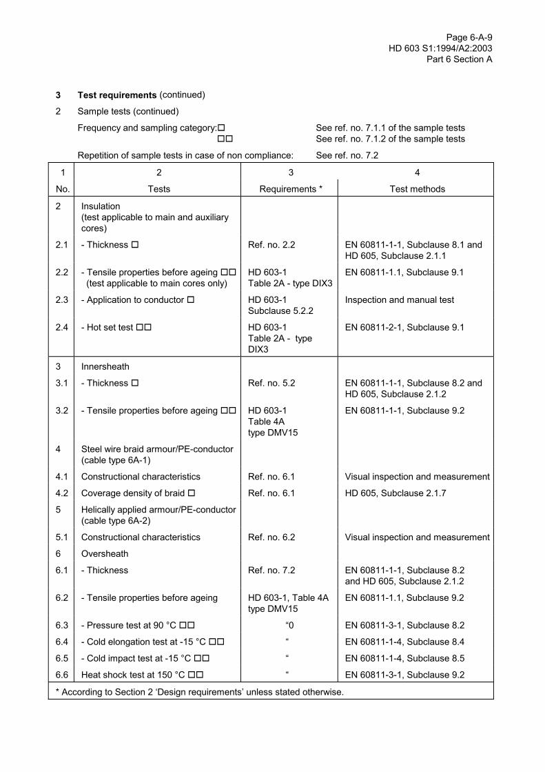
Page 6-A-9 HD 603 S1:1994/A2:2003
Part 6 Section A
3 Test requirements (continued) 2 Sample tests (continued)
Frequency and sampling category: See ref. no. 7.1.1 of the sample tests See ref. no. 7.1.2 of the sample tests
Repetition of sample tests in case of non compliance: See ref. no. 7.2
1 2 3 4
No. Tests Requirements * Test methods
2 Insulation (test applicable to main and auxiliary cores)
2.1 - Thickness
Ref. no. 2.2 EN 60811-1-1, Subclause 8.1 and HD 605, Subclause 2.1.1
2.2 - Tensile properties before ageing
(test applicable to main cores only) HD 603-1 Table 2A - type DIX3
EN 60811-1.1, Subclause 9.1
2.3 - Application to conductor HD 603-1 Subclause 5.2.2
Inspection and manual test
2.4 - Hot set test HD 603-1 Table 2A - type DIX3
EN 60811-2-1, Subclause 9.1
3 Innersheath
3.1 - Thickness Ref. no. 5.2 EN 60811-1-1, Subclause 8.2 and HD 605, Subclause 2.1.2
3.2 - Tensile properties before ageing HD 603-1 Table 4A type DMV15
EN 60811-1-1, Subclause 9.2
4 Steel wire braid armour/PE-conductor (cable type 6A-1)
4.1 Constructional characteristics Ref. no. 6.1 Visual inspection and measurement
4.2 Coverage density of braid Ref. no. 6.1 HD 605, Subclause 2.1.7
5 Helically applied armour/PE-conductor (cable type 6A-2)
5.1 Constructional characteristics Ref. no. 6.2 Visual inspection and measurement
6 Oversheath
6.1 - Thickness Ref. no. 7.2 EN 60811-1-1, Subclause 8.2 and HD 605, Subclause 2.1.2
6.2 - Tensile properties before ageing HD 603-1, Table 4A type DMV15
EN 60811-1.1, Subclause 9.2
6.3 - Pressure test at 90 °C 0 EN 60811-3-1, Subclause 8.2
6.4 - Cold elongation test at -15 °C EN 60811-1-4, Subclause 8.4
6.5 - Cold impact test at -15 °C EN 60811-1-4, Subclause 8.5
6.6 Heat shock test at 150 °C EN 60811-3-1, Subclause 9.2
* According to Section 2 Design requirements unless stated otherwise.

Page 6-A-10 HD 603 S1:1994/A2:2003 Part 6 Section A
3 Test requirements (continued) 2 Sample tests (continued)
1 2
No. Tests
7 Frequency and sampling
7.1 Sampling of cable lengths
7.1.1 Conductor examination and check of dimensions The samples have to be taken of one length from each manufacturing series of the same type and size of cable, but shall be limited to not more than 10 % of the number of lengths in any contract. Conductor examination and measurement of the overall diameter has to be carried on each sample.The sheath thickness measurement has to be carried out on each sample. Insulation thickness measurement has to be carried out on test pieces taken from all main and auxiliary cores of each sample.
7.1.2 Electrical and physical/mechanical tests The test specified have to be made on samples taken from cables manufactured for the contract, provided that the total length in the contract exceeds 2 km of multi-core cables, on the basis given here after.
Length multi-core cables Number of
Above km
Up to and including km
samples
2 20 1
20 40 2
etc.
The electrical tests have to be carried out on all main and auxiliary cores according to Subclause 3.1 of this part: Routine tests. The physical/mechanical test on the sheath has to be carried out on each sample. The physical/mechanical tests have to be carried out on test pieces taken from all main and auxiliary cores of each sample.
7.2 Repetition of sample tests If any sample fails in any of the tests in 3.2 of this part, two further samples shall be taken from the same manufacturing series and submitted to the same test or tests in which the original sample failed. If both additional samples pass the tests, all the cables in the manufacturing series from which they were taken shall be regarded as complying with the requirements. If either of the additional samples fail, the manufacturing series from which they were taken shall be regarded as failing to comply.
* According to Section 2 Design requirements unless stated otherwise.

Page 6-A-11 HD 603 S1:1994/A2:2003
Part 6 Section A
3 Test requirements (continued) 3 Type tests (electrical)
1 2 3 4
No. Tests Requirements * Test methods
1 Electrical resistance
1.1 Conductor resistance Ref. no. 1.5 HD 605, Subclause 3.1.1
1.2.1 Resistance of steel wire braid armour/PE-conductor
Ref. no. 6.1a HD 605, Subclause 3.1.3.1
1.2.2 Additional resistance test Ref. no. 6.1b HD 605, Subclause 3.1.3.1
1.3.1 Helically applied (type 6A-2) armour
Ref. no. 6.2a HD 605 , Subclause 3.1.3.2
1.3.2 Additional resistance test Ref. no. 6.2b HD 605, Subclause 3.1.3.2
2 High voltage test (complete cable) ** - Test voltage - Test duration - Test results
4 kV a.c. 5 min No breakdown
HD 605, Subclause 3.2.1.2 Four core cable without auxiliary cores: a) red and blue --> yellow, yellow/blue and earth b) yellow and yellow/blue --> red, blue and earth c) two adjacent cores --> remaining cores and earth Four core cable without auxiliary cores: a) red and blue --> yellow, yellow/blue, all auxiliary cores and earth b) yellow and yellow/blue --> red, blue, all auxiliary cores and earth c) two adjacent cores and all auxiliary cores --> remaining cores and earth
3 High voltage test on all cores in water - Length of sample - Temperature of water - Duration of water immersion - Test voltage main cores auxiliary cores - Voltage application time - Test result
10 m (20 ± 5) °C ≥ 16 h and ≤ 24 h 2,5 kV 1,5 kV 15 min No breakdown
HD 605, Subclause 3.2.2.2
4 Insulation resistance test at 90 °C on 10 m long sample - Length of sample - Temperature of water - Duration of water immersion - Test result
HD 603-1 Table 2A, type DIX3 10 m (90 ± 2) °C ≥ 2 h HD 603-1 Table 2A, type DIX3
HD 605, Subclause 3.3.1
* According to Section 2 Design requirements unless stated otherwise. * * Concentric conductor or armour, if present, shall be connected to earth.
.
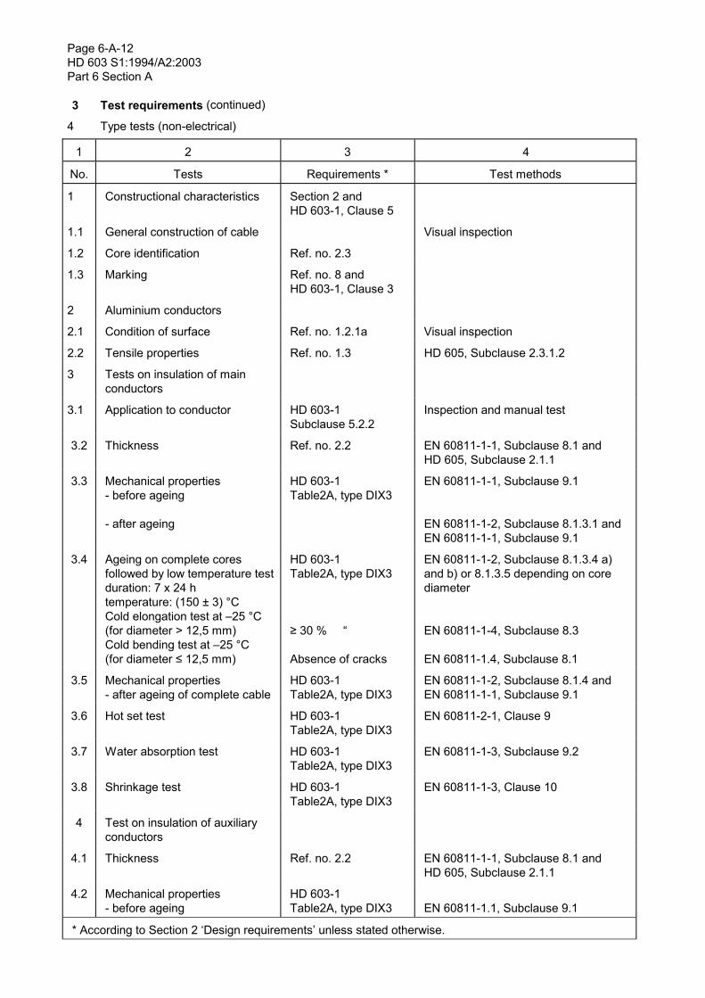
Page 6-A-12 HD 603 S1:1994/A2:2003 Part 6 Section A
3 Test requirements (continued) 4 Type tests (non-electrical)
1 2 3 4
No. Tests Requirements * Test methods
1 Constructional characteristics Section 2 and HD 603-1, Clause 5
1.1 General construction of cable Visual inspection
1.2 Core identification Ref. no. 2.3
1.3 Marking Ref. no. 8 and HD 603-1, Clause 3
2 Aluminium conductors
2.1 Condition of surface Ref. no. 1.2.1a Visual inspection
2.2 Tensile properties Ref. no. 1.3 HD 605, Subclause 2.3.1.2
3 Tests on insulation of main conductors
3.1 Application to conductor HD 603-1 Subclause 5.2.2
Inspection and manual test
3.2 Thickness Ref. no. 2.2 EN 60811-1-1, Subclause 8.1 and HD 605, Subclause 2.1.1
3.3 Mechanical properties - before ageing - after ageing
HD 603-1 Table2A, type DIX3
EN 60811-1-1, Subclause 9.1 EN 60811-1-2, Subclause 8.1.3.1 and EN 60811-1-1, Subclause 9.1
3.4 Ageing on complete cores followed by low temperature test duration: 7 x 24 h temperature: (150 ± 3) °C Cold elongation test at 25 °C (for diameter > 12,5 mm) Cold bending test at 25 °C (for diameter ≤ 12,5 mm)
HD 603-1 Table2A, type DIX3 ≥ 30 % Absence of cracks
EN 60811-1-2, Subclause 8.1.3.4 a) and b) or 8.1.3.5 depending on core diameter EN 60811-1-4, Subclause 8.3 EN 60811-1.4, Subclause 8.1
3.5 Mechanical properties - after ageing of complete cable
HD 603-1 Table2A, type DIX3
EN 60811-1-2, Subclause 8.1.4 and EN 60811-1-1, Subclause 9.1
3.6 Hot set test HD 603-1 Table2A, type DIX3
EN 60811-2-1, Clause 9
3.7 Water absorption test HD 603-1 Table2A, type DIX3
EN 60811-1-3, Subclause 9.2
3.8 Shrinkage test HD 603-1 Table2A, type DIX3
EN 60811-1-3, Clause 10
4 Test on insulation of auxiliary conductors
4.1 Thickness Ref. no. 2.2 EN 60811-1-1, Subclause 8.1 and HD 605, Subclause 2.1.1
4.2 Mechanical properties - before ageing
HD 603-1 Table2A, type DIX3
EN 60811-1.1, Subclause 9.1
* According to Section 2 Design requirements unless stated otherwise.

Page 6-A-13 HD 603 S1:1994/A2:2003
Part 6 Section A
3 Test requirements (concluded) 4 Type tests (non-electrical) (concluded)
1 2 3 4
No. Tests Requirements * Test methods
5 Test on innersheath
5.1 Thickness Ref. no. 5.2 EN 60811-1-1, Subclause 8.2 HD 605, Subclause 2.1.2
5.2 Mechanical properties - before ageing - after ageing
HD 603-1 Table 4A, type DMV15
EN 60811-1-1, Subclause 9.2 EN 60811-1-2, Subclause 8.1 and EN 60811-1-1, Subclause 9.2
5.3 Mechanical properties - after ageing of complete cable
HD 603-1 Table 4A, type DMV15
EN 60811-1-2, Subclause 8.1.4 and EN 60811-1-1, Subclause 9.2
6 Steel wire braid armour / PE-conductor (type 6A-1)
6.1 Constructional characteristics Ref. no. 6.1 Visual inspection and measurement
6.2 Coverage density of braid Ref. no. 6.1 HD 605, Subclause 2.1.7
7 Helically applied armour / PE-conductor (type 6A-2)
7.1 Constructional characteristics Ref. no. 6.2 Visual inspection and measurement
8 Tests on oversheath
8.1 Thickness Ref. no. 7.2 EN 60811-1-1, Subclause 8.2 and HD 605, Subclause 2.1.2
8.2 Mechanical properties - before ageing - after ageing
HD 603-1 Table 4A, type DMV15
EN 60811-1-1, Subclause 9.2 EN 60811-1-2, Subclause 8.1 and EN 60811-1-1, Subclause 9.2
8.3 Mechanical properties - after ageing of complete cable
HD 603-1 Table 4A, type DMV15
EN 60811-1-2, Subclause 8.1 4 and EN 60811-1-1, Subclause 9.2
8.4 Loss of mass HD 603-1 Table 4A, type DMV15
EN 60811-3-2, Subclause 8.2
8.5 Pressure test at 90 °C HD 603-1 Table 4A, type DMV15
EN 60811-3-1, Subclause 8.2
8.6 Cold elongation test at -15 °C HD 603-1 Table 4A, type DMV15
EN 60811-1-4, Subclause 8.4
8.7 Cold impact test at -15 °C HD 603-1 Table 4A, type DMV15
EN 60811-1-4, Subclause 8.5
8.8 Heat shock test at 150 °C HD 603-1 Table 4A, type DMV15
EN 60811-3-1, Subclause 9.2
9 Bending test on complete cable at 0 °C, followed by voltage test of 7,5 kV for 10 min
No breakdown and no visible damage
HD 605, Clause 2.4.1.1 but at (0 ± 2) °C, 3 complete turns and with a cylinder 12 x cable diameter
10 Flame retardance test on complete cable
EN 50265-1 and EN 50265-2
EN 50265-1 and EN 50265-2
* According to Section 2 Design requirements unless stated otherwise.

Page 6-A-14 HD 603 S1:1994/A2:2003 Part 6 Section A
4 Appendix (tables)
Service cable with four solid round copper conductors, XLPE insulated, PVC sheathed, with steel braid armour and protective earth conductor, with or without auxiliary cores with or without auxiliary copper cores Code designation: VO-YMvKas 0,6/1 kV for cables without auxiliary cores VO-YMvKhas 0,6/1 kV for cables with auxiliary cores
Table 1 - General data for cables type 6A-1
Number of cores and nominal cross
sectional area
Steel wire braid/armourPE-conductor
Thickness of XLPE insulation
Thickness of
innersheath
Thickness of
oversheath
Nominal overall
diameter
Main cores
Auxiliary cores 1)
Nominal copper
equivalent cross-
sectional area
Maximum resistance
Main cores
specified values
Auxiliary cores
specifiedvalues
Specified values
Specified values
mm2 mm2 mm2 Ω/km mm mm mm mm mm
4 x 6 - 6 3,08 0,7 - 1,2 1,8 23
4 x 6 4 x 1,5 6 3,08 0,7 0,4 1,2 1,8 23
4 x 6 4 x 2,5 6 3,08 0,7 0,4 1,2 1,8 23
4 x 10 - 10 1,83 0,7 - 1,2 1,8 25
4 x 10 4 x 2,5 10 1,83 0,7 0,4 1,2 1,8 25 1) If requested, the four auxiliary cores may be divided in two cores having the smaller and two having the larger cross-sectional area; the cables may be also provided with two auxiliary cores.
Remark: The specified values for the thickness on insulation for the main cores are in accordance with the values given in HD 603-1, Table 5.

Page 6-A-15 HD 603 S1:1994/A2:2003
Part 6 Section A
4 Appendix (tables) (concluded)
Service cable with four conductors, XLPE insulated, PVC sheathed, with helically applied armour and protective earth conductor, with or without auxiliary cores Provisional code designation: VG-YMvKas 0,6/1 kV for cables without auxiliary cores VG-YMvKhas 0,6/1 kV for cables with auxiliary cores
Table 2 General data for cables type 6A-2
Number of cores and nominal cross
sectional area
Class HD 383 main conductor
Combined-armour/ PE-conductor
Thickness of XLPE insulation
Thickness of
innersheath
Thickness of
oversheath
Nominal overall
diameter
Main cores
Auxiliary cores 1)
Copper
Alumi-nium
Nominal copper
equivalent cross-
sectionalarea
Maximum resistance
Main cores
specified values
Auxiliarycores
specifiedvalues
Specified values
Specified values
mm2 mm2 mm2 Ω/km mm mm mm mm mm
4 x 6 - 1 6 3,08 0,7 - 1,2 1,8 23
4 x 6 4 x 1,5 1 6 3,08 0,7 0,4 1,2 1,8 23
4 x 6 4 x 2,5 1 6 3,08 0,7 0,4 1,2 1,8 23
4 x 10 - 1 10 1,83 0,7 - 1,2 1,8 25
4 x 10 4 x 2,5 1 10 1,83 0,7 0,4 1,2 1,8 25
4 x 16 - 2 1 10 1,83 0,7 - 1,2 2,0 26
4 x 16 4 x 1,5 2 1 10 1,83 0,7 0,4 1,2 2,0 26
4 x 25 - 2 25 0,727 0,9 - 1,2 2,0 32
4 x 25 4 x 2,5 2 25 0,727 0,9 0,4 1,2 2,0 32 1) If requested, the four auxiliary cores may be divided in two cores having the smaller and two having the larger cross-sectional area; the cables may be also provided with two auxiliary cores.
Remark: The specified values for the thickness on insulation for the main cores are in accordance with the values given in HD 603-1, Table 5.
4 Appendix - Guide to use 1 Scope
This "Guide to use" is applicable to cables according to Section 6-A of HD 603.
2 Object
The object of this "Guide to use" is to provide recommendations for the storage, transport and handling of the cables.

Page 6-A-16 HD 603 S1:1994/A2:2003 Part 6 Section A
4 Appendix - Guide to use (continued) 3 Recommendations for storage, transport and handling
3.1 Delivery
When delivered on a drum the core diameter of the drum shall not be less than:
- 14 times the outer diameter of the cable for braided cables,
- 16 times the outer diameter of the cable for cables with helically applied armour / PE-conductor.
The distance between the outer cable layer and the head of the drum flange shall be sufficiently high to avoid damages to the cable.
Short cable lengths may be coiled to rings and transported and stored horizontally. The bending radii shall not be less than the above mentioned values.
3.2 Cable end sealing
The cable ends shall be sealed waterproof during transport, storage and laying.
3.3 Transport
For the transport of filled up cable reels only suitable carriers shall be used.
Cables stored at temperatures which fall below those recommended for installation shall not be subject to any mechanical stress including shocks, impact, bending and torsion.
It shall be prevented that drum flanges come in touch with the cable of another drum.
For loading and unloading of cable drums suitable lifting and hoisting equipment shall be used; never drop a drum on the ground or on a buffer.
See also relevant figures.
Filled up cable drums shall be rolled only on short distances over plain solid ground in the direction indicated.
The cable end shall be tightened.
3.4 Lowest temperature for cable laying and installation
Sheath of PVC is liable to cracking at low temperatures in case of blows to the cable or excessive bending. Care should therefore be taken during transport, laying and installation.
Lowest temperature of cable during installation is 0 °C under normal conditions of care.
This temperature is valid for the cable itself and not for the environment. If possible, the temperature of the cable shall be raised to at least + 10 C before laying, e.g. in a heated building, to facilitate handling and to reduce the risk of damages.
3.5 Pulling loads
It is assumed that the cable route is well designed for the laying procedure with well established curves and a sufficient number of cable rollers. Special attention shall be paid to the required minimum bending radii (see Subclause 3.6 of this appendix). The pulling forces shall be permanently supervised during the pull-in procedure.
The pulling force shall be evenly divided over the main conductors.
The maximum pulling force (P) shall be calculated as follows:
P = S σ
where P is in N
σ is maximum tensile stress in conductor, viz.
50 N / mm2 for copper conductors
20 N / mm2 for aluminium conductors
Page 6-A-17 HD 603 S1:1994/A2:2003
Part 6 Section A
4 Appendix - Guide to use (continued) S is total cross-sectional area in mm2 of the main conductors (ignoring screens, concentric conductors and auxiliary conductors).
In case of using a cable stocking, the total pulling force shall not exceed 1 000 N.
3.6 Bending radius
During installation the internal bending radius of the cable shall not be smaller than 10 D, where D is the overall diameter of the cable. This value may be reduced to 8 D in case of a careful, one single time bending of the cable end.
Bending nearby the temperature limits given in Subclause 3.4 of this appendix should be carried out extra carefully.

Page 6-A-18 HD 603 S1:1994/A2:2003 Part 6 Section A
4 Appendix - Guide to use (concluded)
STORAGE
Keep the drum standing upright, using wedges in the heels of the
flanges
Only drums with protection lagging may be piled flange on flange. Lower
layer to be secured over full drum width
Never lay them flat
TRANSPORT
Roll the drum in the direction used
during cable reeling Drums may be lifted either by crane
or fork-lift truck
DE-REELING
De-reel in this way Never de-reel in this way
RE-WINDING
Recommended Not recommended
Page 7-A-0 HD 603 S1:1994/A2:2003
Part 7 Section A
SECTION 7-A - CABLES WITH HEPR INSULATION AND PVC SHEATH WITH CONCENTRIC CONDUCTOR (TYPE 7A)
Replace Section 7-A
by the following A2 referred new Section 7-A:


Page 7-A-1 HD 603 S1:1994/A2:2003
Part 7 Section A
SECTION 7-A - CABLES WITH HEPR INSULATION AND PVC SHEATH WITH CONCENTRIC CONDUCTOR (TYPE 7A)

Page 7-A-2 HD 603 S1:1994/A2:2003 Part 7 Section A
CONTENTS
1 General--------------------------------------------------------------------------------------------------------------------------- 3
2 Design requirements---------------------------------------------------------------------------------------------------------- 4
1 Conductor ------------------------------------------------------------------------------------------------------------- 4
1.1 Material 1.2 Dimensions 1.3 Tensile strength and elongation at break 1.4 Electrical resistance of conductors
2 Insulation -------------------------------------------------------------------------------------------------------------- 4
2.1 Material 2.2 Insulation thickness 2.3 Core identification
3 Assembly-------------------------------------------------------------------------------------------------------------- 4
3.1 Laying up of cores 3.2 Fillers 3.3 Inner covering
4 Concentric conductor----------------------------------------------------------------------------------------------- 5
4.1 Design 4.2 Clearance between adjacent wires 4.3 Tape over concentric conductor
5 Outer sheath---------------------------------------------------------------------------------------------------------- 6
5.1 Material 5.2 Sheath thickness 5.3 Colour
6 Outer diameter ------------------------------------------------------------------------------------------------------- 6
7 Marking ---------------------------------------------------------------------------------------------------------------- 6
7.1 Meter marking 7.2 Continuity of marks 7.3 Durabiity 7.4 Legibility
8 Cable designation --------------------------------------------------------------------------------------------------- 6
9 Packing and shipping lengths ------------------------------------------------------------------------------------ 6
3 Test requirements ------------------------------------------------------------------------------------------------------------- 7
1 Routine tests --------------------------------------------------------------------------------------------------------- 7 2 Sample tests---------------------------------------------------------------------------------------------------------- 8 3 Type tests ------------------------------------------------------------------------------------------------------------- 9
4 Appendix (tables) -------------------------------------------------------------------------------------------------------------11
5 Guide to use -------------------------------------------------------------------------------------------------------------------20
Page 7-A-3 HD 603 S1:1994/A2:2003
Part 7 Section A
REFERENCES
References are made in Section 7-A of HD 603, to other parts of this HD and to other Harmonization Documents, European and International Standards as follows:
HD 383 Conductors of insulated cables First supplement: Guide to the dimensional limits of circular conductors (endorsing IEC 60228 and 60228A)
HD 605 Electric cables Additional test methods
EN 50265 (series) Common test methods for cables under fire conditions Test for resistance to vertical flame propagation for a single insulated conductor or cable
EN 60811 (series) Insulating and sheathing materials of electric cables - Common test methods
ISO 2859-1 Sampling procedures for inspection by attributes Part 1: Sampling schemes indexed by acceptance quality limit (AQL) for lot-by-lot inspection
In all cases reference to another HD or International Standard implies the latest edition of that document.
1 General
This standard specifies the construction, dimensions and test requirements of unarmoured cables with HEPR insulation, single or multi-core with concentric conductor. Cables are 0,6/1 kV rated voltage and for fixed installation.
(a) Insulating material
The insulation covered by this standard shall consist of hard ethylene propylene rubber
(b) Rated voltage
0,6/1 kV
Definitions: see HD 603-1, Subclause 2.3
(c) Highest rated temperatures
(i) Normal operation phase conductor temperature 90 °C
(ii) Short-circuit temperatures: for phase conductor 250 °C for concentric conductor 160 °C
(d) Sheathing material
The sheath material shall consist of PVC compound, suitable for the conductor operating temperature in accordance with the above point (c).

Page 7-A-4 HD 603 S1:1994/A2:2003 Part 7 Section A
2 Design requirements
No. Cable component Requirements HD Additional
1 Conductor HD 603-1 Subclause 5.1
The conductor shall be regular and exempt from defects. Annealed plain copper or aluminium wires The conductor shall be: - round solid for 6 mm2
- round stranded compact for the other cable sections.
1.1 Material Purity of: a) copper b) aluminium
HD 603-1 Subclause 5.1.1
Not less than 99,9 % Not less than 99,5 %
1.2 Dimensions and number of wires of compacted stranded circular conductors
HD 383 Appendix, Tables 2 and 3
1.3 Tensile strength and elongation at break (before stranding and compacting) a) Copper wire b) Aluminum wire (d ≥ 1,2 mm)
Breaking Minimum elongation at break (%) load (N/mm2) 0,1 < d ≤ 0,3 0,3 < d ≤ 1,0 d > 1,0 220 / 300 15 20 20 120 / 190 - - 1 d being the wire diameter
1.4 Electrical resistance of conductor
HD 603-1 Subclause 5.1.2
Appendix, Tables 2 and 3
2 Insulation HD 603-1 Subclauses 5.2 and 5.1.3
For single-core cables a synthetic tape may be applied over the insulation
2.1 Material HD 603-1 Table 2C - DIH 1
2.2 Insulation thickness
HD 603-1 Subclause 5.2.3
Appendix, Tables 5 to 9
2.3 Core identification
- Single-core cable
- Three-core cable
HD 603-1, Clause 4
Black
Blue - Brown - Black 3 Assembly 3.1 Laying up of cores Cores shall be helically assembled with left sense. The pitch
being
• for cables having conductor section up to and including 25 mm2: not more than 15 times the maximum outer cable diameter specified,
• for other cables not less than 1,3 times the wave period of the concentric conductor.
A synthetic tape may be applied longitudinally over the laid up of cores.

Page 7-A-5 HD 603 S1:1994/A2:2003
Part 7 Section A
2 Design requirements (continued)
No. Cable component Requirements HD Additional
3.2
3.2.1
3.2.2
Fillers
Central filler
Overall filler
HD 603-1 Subclause 5.4
The fillers shall be manufactured by a non -hygroscopic material and that not contaminating insulation and easy to be removed from the cores. It shall consist of non-hygroscopic textile yarn or by a combination of an extruded compound based on non-vulcanised elastomeric material with textile yarn. The central filler is mandatory for conductor cross section greater than 25 mm2. It shall consist of an extruded compound based on non-vulcanised elastomeric material non-hygroscopic and shall be penetrate between the cores and must allow easy separation of the concentric conductor wires and cover the laid up cores without gaps.It may be replaced by the inner covering.
3.3 Inner Covering HD 603-1 Subclause 5.5
Over the cores assembly shall be applied an inner covering consisting of a cylindrical layer of extruded compound. It shall be based on a non- vulcanised non-hygroscopic elastomeric material.
4 Concentric conductor
HD 603-1 Subclause 5.7
4.1 Design It shall consist of plain annealed copper wires, with an equalising plain annealed copper tape, optional for single-core cables. Minimum number of wires and electrical characteristics are specified in Appendix, Table 4. For cables having a phase conductor cross section up to and including 25 mm2, the concentric wires shall be applied in the form of a continuous helix or in the form of helix with a sense of rotation periodically inverted having a pitch not exceeding 15 times the outer maximum cable diameter (see Tables 5, 6 and 7).The ratio between the length of straightened wires and the length of the cable shall be greater than 1,03 for multicore cables or 1,02 for single-core cables. For cable having a phase conductor cross section higher than 25 mm2 , the concentric wires shall be applied in the form of a helix with a sense of rotation periodically inverted: the period of the resulting sinusoids shall not be greater than 350 mm for 3 x 50 + 25 C 450 mm for 3 x 95 + 50 C and 3 x 95 + 35 C 500 mm for 3 x 150 + 95 C and 3 x 150 + 50 C 500 mm for 3 x 240 + 95 C
The ratio between the length of straightened wires and the length of the cable shall be greater than 1,05. The equalising tape, if any, shall be applied helically. For helically applied concentric wires it should be in the opposite direction.

Page 7-A-6 HD 603 S1:1994/A2:2003 Part 7 Section A
2 Design requirements (concluded)
No. Cable component Requirements HD Additional
4.2 Clearance between adjacent wires
The maximum clearance shall be ≤ 4 mm. An increase in the gap size up to 8 mm is allowed for 10 % of the spaces rounded to the lower integer.
4.3 Tape over concentric conductor
A non hygroscopic synthetic tape may be helically applied over the concentric conductor.
5 Outer Sheath HD 603-1 Subclause 5.8
5.1 Material HD 603-1 Table 4A DMV 13
Single extruded layer of PVC compound, uniform and compact, without blisters and other surface defects.
5.2 Sheath thickness HD 603-1 Subclause 5.8.3
Appendix, Tables 5 to 9
5.3 Color Grey (RAL 7001)
6 Outer diameter Appendix, Tables 5 to 9
7 Marking HD 603-1 Clause 3
Following legend shall be embossed on the outer surface of the sheath at least:
- cable designation - manufacturer name - manufacturing year
7.1 Meter marking HD 603-1 Subclause 3.2
A form of sequential marking may be provided on the surface of the cable to enable an approximate determination of any drum length.
7.2 Continuity of marks HD 603-1 Subclause 3.1.1
Clearance between adjacent marks may be increased up to 1 000 mm when a meter marking is applied.
7.3 Durability HD 603-1 Subclause 3.3
7.4 Legibility HD 603-1 Subclause 3.4
8 Cable designation Appendix, from Table 1A to Table 1B
9 Packing and shipping lengths
HD 603-1 Clause 7
Appendix, Table 10

Page 7-A-7 HD 603 S1:1994/A2:2003
Part 7 Section A
3 Test requirements 1 Routine tests
1 2 3 4
No. Tests Requirements * Test methods
1 Electrical tests
1.1 () (*)
Electrical resistance of phase conductors Appendix, Tables 2 and 3 HD 605 Subclause 3.1.1
1.2 () (*)
Electrical resistance of concentric conductor on a complete cable length (The electrical resistance shall be measured according to both Subclauses 3.1.1 and 3.1.4.2 of HD 605.)
Appendix, Table 4, when tested according to HD 605, Subclause 3.1.1 and 110 % of the same value when tested according to HD 605, Subclause 3.1.4.2
HD 605 Subclauses 3.1.1 and 3.1.4.2
1.3 ()(*)
Voltage test on complete cable No breakdown HD 605 Subclause 3.2.1
1.3.1 Test voltage: 4 kV a.c. or 12 kV d.c. (gradually increased to required value in 1 min)
1.3.2 Test duration: 5 min
1.4
Voltage test on oversheath for concentric cables
1.4.1 Spark test during manufacturing No breakdown HD 605, Subclause 3.6.3
1.4.2 ()
Voltage test No breakdown HD 605 Subclause 3.2.3.1
The complete cable shall be water immersed at room temperature for at least 1 h.
1.4.2.1 Test voltage: 4 kV a.c. or 12 kV d.c.
1.4.2.2 Test duration: 5 min
1.5 ()
1.5.1
Insulation resistance at ambient temperature Test voltage between 80 V d.c. and 500 V d.c. (at least 24 h after a d.c. voltage test)
Subclause 2.1
HD 605 Subclauses 3.3.2 and 3.3.3 HD 605 Subclause 3.3.1
* According to Section 2 Design requirements unless stated otherwise. () () and (*): see final note.

Page 7-A-8 HD 603 S1:1994/A2:2003 Part 7 Section A
3 Test requirements (continued)
2 Sample tests
1 2 3 4
No. Tests Requirements * Test methods
1 Construction characteristics and dimensions
1.1 ()
Conformity to the general requirements Subclauses 1.2, 2.3, 4.1, 5.3 and Clause 7
Visual examination and measurement
1.2 ()
Insulation thickness measurement Subclause 2.2 HD 605 Subclause 2.1.1
1.3 ()
Sheath thickness measurement Subclause 5.2 HD 605 Subclause 2.1.2
1.4 ()
Outer cable diameter measurement Clause 6 HD 605 Subclause 2.1.3.1
1.5 ()
Clearance between concentric wires Subclause 4.2 HD 605 Subclause 2.1.6.2
2 ()
Hot set test HD 603-1 Table 2C - DIH 1
EN 60811-2-1 Clause 9
3 Marking
3.1 ()
Durability Subclause 7.3 HD 605 Subclause 2.5.4
3.2 ()
Legibility Subclause 7.3 Visual examination
4 Insulation physical characteristics
4.1 ()
Mechanical properties before ageing Subclause 2.1 EN 60811-1-1 Subclause 9.1
4.2 ()
Tensile modulus measurement at room temperature elongation: 150 %
Subclause 2.1 HD 605 Subclause 2.2.6.1
5 Sheath physical characteristics
5.1 ()
Mechanical characteristics before ageing Subclause 5.1 EN 60811-1-1 Subclause 9.2
5.2 ()
Heat shock test Subclause 5.1 EN 60811-3-1 Subclause 9.2
6 Test on complete cable
6.1 ()
Compression test
No breakdown shall occur during the voltage test.
HD 605 Subclause 2.2.3
* According to Section 2 Design requirements unless stated otherwise. () () and (*): see final note.

Page 7-A-9 HD 603 S1:1994/A2:2003
Part 7 Section A
3 Test requirements (continued)
3 Type tests
Cable samples to be submitted to type tests must have passed positively all routine and sample tests.
1 2 3 4
No. Tests Requirements * Test methods
1 Insulation physical characteristics
1.1 Mechanical properties after ageing in air oven Subclause 2.1 EN 60811-1-1 Subclause 9.1
1.1.1 Ageing condition Subclause 2.1 EN 60811-1-2 Subclause 8.1.3.2
1. 2 Mechanical properties after ageing in air bomb Subclause 2.1 EN 60811-1-1 Subclause 9.1
1.2.1 Ageing condition Subclause 2.1 EN 60811-1-2 Subclause 8.2
1.3 Ozone resistance test Subclause 2.1 EN 60811-2-1 Clause 8
1.4 Water absorption test (gravimetric method) Subclause 2.1 EN 60811-1-3 Subclause 9.2
2 Sheath physical characteristics
2.1 Mechanical properties after ageing in air oven
2.1.1 Ageing conditions Subclause 5.1 EN 60811-1-2 Subclause 8.1
2.2 Hot pressure test Subclause 5.1 EN 60811-3-1 Subclause 8.2
2.3 Cold bending or elongation test Subclause 5.1 EN 60811-1-4 Subclause 8.2 or 8.4
2.4 Cold impact test Subclause 5.1 EN 60811-1-4 Subclause 8.5
* According to Section 2 Design requirements unless stated otherwise.
Page 7-A-10 HD 603 S1:1994/A2:2003 Part 7 Section A
3 Test requirements (concluded)
3 Type tests (concluded)
1 2 3 4
No. Tests Requirements * Test methods
3 Test on complete cable
3.1 Compatibility test HD 603-1 Table 2C - DIH 1 Table 4A - DMV 13
HD 605 Subclause 2.4.12.2
3.2 3.2.1 3.2.2
3.2.3
3.2.4
Bending test Sample length: 3,5 times the bending diameter Preconditioning temperature: 0 ± 3 °C for a time in min not less than twice the cable diameter in mm, with a minimum of 1 h. It is allowed to precondition. The cable sample just bent on the cylinder. Cylinder diameter: 16 (D + d); tolerance: (0 ± 5 %) D = diameter of cable d = diameter of conductor Electrical test: after the bending cycles the cable shall be bent in U form then immersed in water and submitted to a.c. test at 4 U0 + 2,5 kV for 10 min leaving the cable ends in air. By agreement between manufacturer and purchaser a 9 U0 + 6 kV d.c. test can be performed.
No breakdown shall occur during the voltage test. After the electrical test, starting from the center of the sample length, a length of 18 D shall be careful taken apart and examined. No breaks of the insulated conductors, of the concentric conductors, of the insulation and of the over sheath shall be found.
HD 605 Subclause 2.4.1.1
3.3 Flame non-propagation test EN 50265-1 and EN 50265-2-1
* According to Section 2 Design requirements unless stated otherwise.
NOTE The number of lengths to be checked is stated according to ISO 2859/1 as follows:
() General inspection level I, single sampling for reduced inspection with AQL = 2,5 %
() General inspection level II, single sampling for normal inspection with AQL = 1,0 %
As sample test, the mechanical characteristics of insulation and sheath shall be intended before ageing.
(*) The manufacturer shall give to the purchaser the results of the electrical conductors resistance of phase and concentric conductors measurement and of the insulation voltage test carried out on all the cable lengths.

Page 7-A-11 HD 603 S1:1994/A2:2003
Part 7 Section A
4 Appendix (tables)
Table 1A - Single-core cables
A) Single-core
Cable designation: Code, rated voltage and cross sectional area (mm2)
UG7CR 0,6/1 kV 1 x 6 + 6 C RG7CR 0,6/1 kV 1 x 16 + 16 C RG7CR 0,6/1 kV 1 x 25 + 25 C
B) Schematic drawing
I II III IV V
I - Conductor IV - Outersheath II - Insulation V - Marking III - Concentric conductor
The designations are provisional.

Page 7-A-12 HD 603 S1:1994/A2:2003 Part 7 Section A
4 Appendix (tables) (continued)
Table 1B - Three-core cables
A) Copper conductor cable
Cable designation: Code, rated voltage and cross sectional area (mm2)
UG7OCR 0,6/1 kV 3 x 6 + 6 C RG7OCR 0,6/1 kV 3 x 16 + 16 C RG7OCR 0,6/1 kV 3 x 25 + 25 C RG7OCR 0,6/1 kV 3 x 50 + 25 C RG7OCR 0,6/1 kV 3 x 95 + 50 C RG7OCR 0,6/1 kV 3 x 150 + 95 C
B) Schematic drawing
V I II III IV VI
I - Conductor IV - Concentric conductor II - Insulation V- Outersheath III - Fillers and inner covering VI - Marking
The designations are provisional.
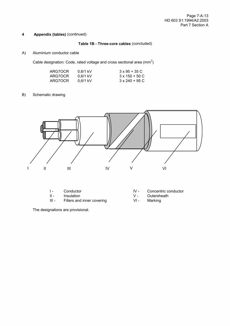
Page 7-A-13 HD 603 S1:1994/A2:2003
Part 7 Section A
4 Appendix (tables) (continued)
Table 1B - Three-core cables (concluded)
A) Aluminium conductor cable
Cable designation: Code, rated voltage and cross sectional area (mm2)
ARG7OCR 0,6/1 kV 3 x 95 + 35 C ARG7OCR 0,6/1 kV 3 x 150 + 50 C ARG7OCR 0,6/1 kV 3 x 240 + 95 C
B) Schematic drawing
V I II III IV VI
I - Conductor IV - Concentric conductor II - Insulation V - Outersheath III - Fillers and inner covering VI - Marking
The designations are provisional.
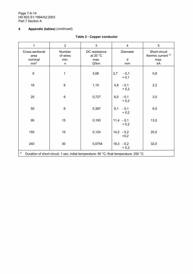
Page 7-A-14 HD 603 S1:1994/A2:2003 Part 7 Section A
4 Appendix (tables) (continued)
Table 2 - Copper conductor
1 2 3 4 5
Cross-sectional area
nominal mm2
Number of wires
min. n
DC resistance at 20 °C
max. Ω/km
Diameter d
mm
Short-circuit thermic current *)
max. kA
6 16 25 50 95 150 240
1 6 6 6 15 15 30
3,08 1,15 0,727 0,387 0,193 0,124 0,0754
2,7 - 0,1 + 0,1 4,8 - 0,1 + 0,2 6,0 - 0,1 + 0,2 8,1 - 0,1 + 0,2 11,4 - 0,1 + 0,2 14,2 - 0,2 +0,2 18,3 - 0,2 + 0,3
0,8 2,2 3,5 6,5 13,0 20,0 32,0
*) Duration of short-circuit: 1 sec; initial temperature: 90 °C; final temperature: 250 °C.
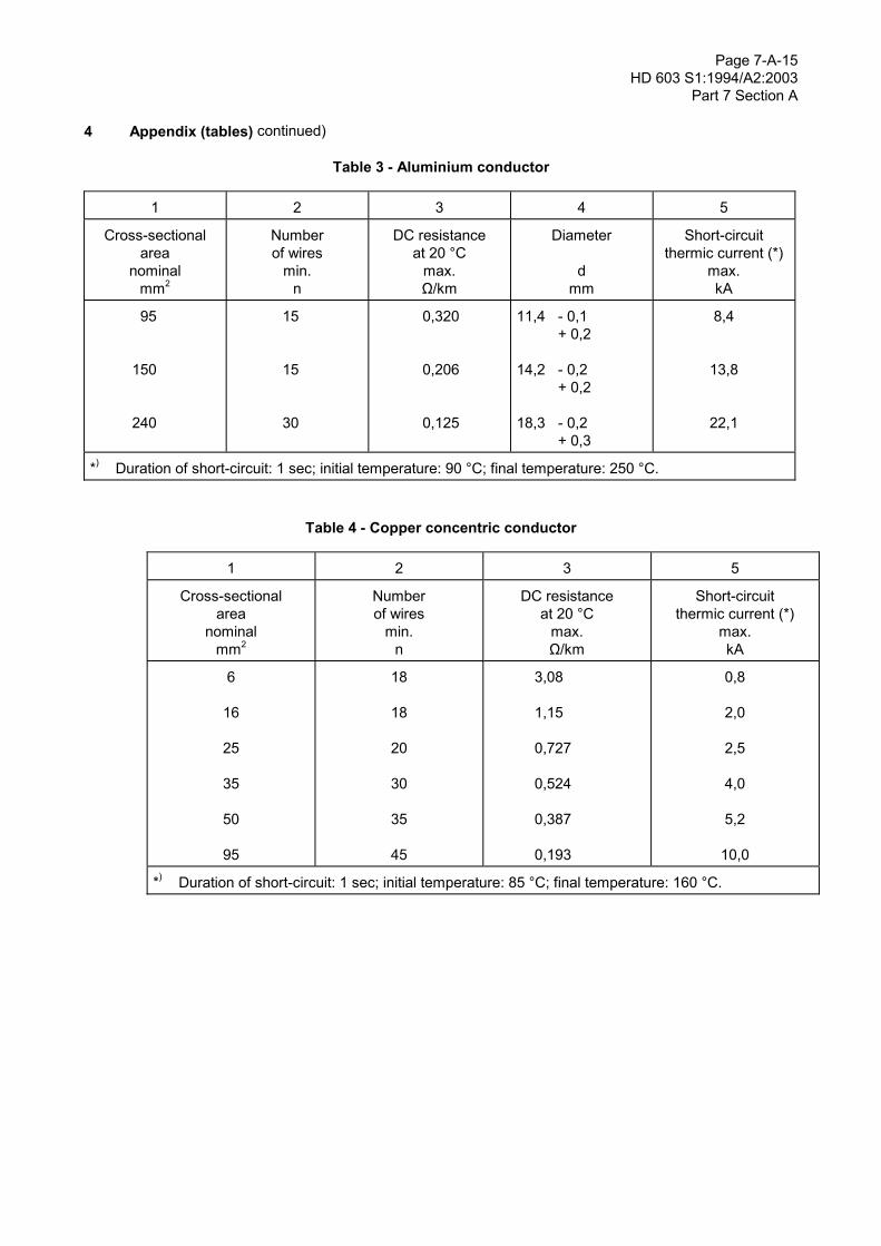
Page 7-A-15 HD 603 S1:1994/A2:2003
Part 7 Section A
4 Appendix (tables) continued)
Table 3 - Aluminium conductor
1 2 3 4 5
Cross-sectional area
nominal mm2
Number of wires
min. n
DC resistance at 20 °C
max. Ω/km
Diameter d
mm
Short-circuit thermic current (*)
max. kA
95 150 240
15 15 30
0,320 0,206 0,125
11,4 - 0,1 + 0,2 14,2 - 0,2 + 0,2 18,3 - 0,2 + 0,3
8,4
13,8
22,1
*) Duration of short-circuit: 1 sec; initial temperature: 90 °C; final temperature: 250 °C.
Table 4 - Copper concentric conductor
1 2 3 5
Cross-sectional area
nominal mm2
Number of wires
min. n
DC resistance at 20 °C
max. Ω/km
Short-circuit thermic current (*)
max. kA
6
16
25
35
50
95
18
18
20
30
35
45
3,08 1,15 0,727 0,524 0,387 0,193
0,8
2,0
2,5
4,0
5,2
10,0
*) Duration of short-circuit: 1 sec; initial temperature: 85 °C; final temperature: 160 °C.

Page 7-A-16 HD 603 S1:1994/A2:2003 Part 7 Section A
4 Appendix (tables) (continued)
Table 5 0,6/1 kV copper conductor - Hard EPR insulation - Copper concentric conductor - PVC outersheath
Cross sectional area
Mean thickness of insulation S1
Diameter on insulation
Mean thickness of sheath S2
Outer diameter
Nominal mm2
Min. mm
Approx. mm
Min. mm
Min. mm
Max. mm
1 x 6 + 6 C
1 x 16 + 16 C
1 x 25 + 25 C
1,2
1,2
1,2
5,1
7,2
8,4
1,4
1,4
1,6
8,6
10,7
12,3
12,3
14,5
16,2
Cross sectional area
Weight Current carrying capacity *)
Nominal
mm2
Approx.
kg/km
Cables laid in air A
Cables laid in duct in air
A
Cables laid in ground
A
Cables laid in duct in ground
A
1 x 6 + 6 C
1 x 16 + 16 C
1 x 25 + 25 C
180
400
590
58
107
144
52
95
127
78
141
183
62
113
145
*) Phase central conductor temperature: 90 °C; neutral concentric conductor temperature: 85 °C; and moreover for cables laid in free air and in duct in air: air temperature 30 °C, for cables laid in ground and in duct in ground: ground thermal resistivity: 1 K.m/W, ground temperature: 20 °C, depth of laying 0,8 m.

Page 7-A-17 HD 603 S1:1994/A2:2003
Part 7 Section A
4 Appendix (tables) (continued)
Table 6 0,6/1 kV copper conductor - Hard EPR insulation - Copper concentric conductor - PVC outersheath
Cross sectional area
Mean thickness of insulation S1
Diameter on insulation
Mean thickness of Sheath S2
Outer diameter
Nominal mm2
Min. mm
Approx. mm
Min. mm
Min. mm
Max. mm
3 x 6 + 6 C
3 x 16 + 16 C
3 x 25 + 25 C
3 x 50 + 25 C
3 x 95 + 50 C
3 x 150 + 95 C
0,7
0,7
0,9
1,0
1,1
1,4
4,1
6,2
7,8
10,1
13,6
17,0
1,8
2,2,
2,2
2,2
2,2
2,4
15,2
21,6
25,1
30,2
37,9
46,6
19,1
25,9
29,6
34,7
42,4
51,5
Cross sectional area
Weight Current carrying capacity *) Short-circuit dynamics current
Nominal
mm2
Approx.
kg/km
Cables laid in air
A
Cables laid in duct in air
A
Cables laid in ground
A
Cables laid in duct in ground
A
Max.
kA
3 x 6 + 6 C
3 x 16 + 16 C
3 x 25 + 25 C
3 x 50 + 25 C
3 x 95 + 50 C
3 x 150 + 95 C
450
1 050
1 550
2 350
4 200
6 700
54
100
133
198
306
407
48
89
117
175
269
359
66
114
145
208
311
389
53
91
116
166
249
311
20
25
30
35
40
45
*) Phase central conductor temperature: 90 °C; neutral concentric conductor temperature: 85 °C; and moreover for cables laid in free air and in duct in air: air temperature 30 °C, for cables laid in ground and in duct in ground: ground thermal resistivity: 1 K.m/W, ground temperature: 20 °C, depth of laying 0,8 m.

Page 7-A-18 HD 603 S1:1994/A2:2003 Part 7 Section A
4 Appendix (tables) (continued)
Table 7 - 0,6/1 kV aluminium conductor - Hard EPR insulation - Copper concentric conductor - PVC outersheath
Cross sectional area
Mean thickness of insulation S1
Diameter on insulation
Mean thickness of sheath S2
Outer diameter
Nominal mm2
Min. mm
Approx. mm
Min. mm
Min. mm
Max. mm
3 x 95 + 35 C
3 x 150 + 50 C
3 x 240 + 95 C
1,1
1,4
1,7
13,8
17,2
21,9
2,2
2,4
2,8
37,9
46,6
57,7
42,4
51,5
63,3
Cross sectional area
Weight Current carrying capacity *) Short-circuit dynamics current
Nominal
mm2
Approx.
kg/km
Cables laid in air
A
Cables laid in duct in air
A
Cables laid in ground
A
Cables laid in duct in ground
A
Max.
kA
3 x 95 + 35C
3 x 150 + 50 C
3 x 240 + 95 C
2 400
3 500
5 900
239
318
425
210
280
375
245
305
405
195
245
325
40
45
55
*) Phase central conductor temperature: 90 °C; neutral concentric conductor temperature: 85 °C; and moreover for cables laid in free air and in duct in air: air temperature 30 °C, for cables laid in ground and in duct in ground: ground thermal resistivity: 1 K.m/W, ground temperature: 20 °C, depth of laying 0,8 m.

Page 7-A-19 HD 603 S1:1994/A2:2003
Part 7 Section A
4 Appendix (tables) (continued)
Table 8 Spare
Table 9 Spare
Table 10 - Packing and shipping lengths
Cable type
(provisional designation)
Cross sectional area
mm2
Coil length
m
Shipping length
m
UG7CR
RG7CR
RG7CR
UG7OCR
RG7OCR
RG7OCR
RG7OCR
RG7OCR
RG7OCR
ARG7OCR
ARG7OCR
ARG7OCR
1 x 6 + 6 C
1 x 16 + 16 C
1 x 25 + 25 C
3 x 6 + 6 C
3 x 16 + 16 C
3 x 25 + 25 C
3 x 50 + 25 C
3 x 95 + 50 C
3 x 150 + 95 C
3 x 95 + 35 C
3 x 150 + 50 C
3 x 240 + 95 C
100
-
-
-
-
-
-
-
-
-
-
-
500
500
500
500
500
500
500
500
500
500
500
500
Nominal and actual cable length
Unless otherwise agreed between customer and manufacturer, each delivery cable length shall not differ by more than +/- 3 % with respect to the nominal length indicated either in the order or in the relevant specification.
Lots of coils or drums of cables of the same type and nominal cross section type may contain up to 10 % of the cable lengths (rounded at the upper integer) shorter than the nominal length; if the lot contains no more than 10 coils or drums, two shorter cable lengths are admitted. In any case actual cable lengths shorter than 100 m are not admitted.
If the total delivery length of shipping lot is not multiple of the normal length, the remaining cable length shall not be considered as a part of the shorter lengths.
The term "lot" indicates the whole cable lengths taken together to form a single delivering.

Page 7-A-20 HD 603 S1:1994/A2:2003 Part 7 Section A
4 Appendix (continued)
Drums and coils
Nominal cable lengths having weight not exceeding 35 Kg are usually supplied as coiled, while cable lengths having greater weight are wound on drums. Unless otherwise agreed between customer and manufacturer, each coil or drum shall contain a single cable length.
Cable lengths either coiled or wound on drum shall be protected in adequate manner to prevent damages and/or infringements.
The inner diameter of coils or the inner diameter of drums wound shall not be less than 12 D; D being the outer cable diameter.
Nominal data
Each drum or coil shall be identified by a plate, label or indelible inscription on which the following data shall be indicated:
- manufacturer name or logo;
- cable identification (cross section, nominal voltage, etc;) (abbreviations are allowed with reference to the relevant standard);
- possible indication to the standard the cable is referred to;
- actual cable length.
5 Guide to use
1 SCOPE This Guide to use is valid for the 0,61 kV multicore and single-core power distribution cables, according to HD 603 -7-A.
2 OBJECT
The object of this Guide to use is to provide recommendations for the selection, storage, transportation and installation of the cables specified under Clause 1 Scope. NOTE 1 Safety requirements as well as rule of installations are not considered in this Guide to use, as they are covered by the relevant national regulations and laws.
3 RECOMMENDATION FOR USE 3.1 Permissible applications
Cables according to HD 603-7-A may be used indoor, also in wet locations, and outdoor for fixed installations on wall and metallic structures,and may be directly buried in soil.
3.2 Highest permissible voltage
Cables rated at Uo/U = 0,6/1 kV are used in a.c. systems with a maximum voltage of 1,2 kV; they may be also used in d.c. systems having a rated operation voltage between conductors and earth not higher than 0,9 kV.
3.3 Concentric conductor
The concentric conductor, if any, may be used as a ground neutral or protection conductor.

Page 7-A-21 HD 603 S1:1994/A2:2003
Part 7 Section A
5 Guide to use (continued) 4 RECOMMENDATIONS FOR STORAGE AND TRANSPORT 4.1 Packing
By agreement between manufacturer and costumer the cable shall be delivered in coils or in drums. 4.2 Delivery
Cables shall be protected to avoid any damage during storage and transport. The radius of the drum core shall not be less than the minimum bending radius under controlled conditions given in 5.4 of this "Guide to use". The distance between the outer cable layer in the filled drum and the protection lagging shall be sufficient to avoid damages of the cable. Care shall be taken to avoid that nails, screws, etc. used in drum manufacturing or lagging fixing can cause damage to the cable.
4.3 Cable-end sealing
Cable-ends shall be sealed against water and moisture penetration during transport, storage and laying.
4.4 Transport
4.4.1 Drum transport For the transport of cable filled drums only suitable carriers shall be used. Cable filled drums shall be transported only with the drum axes in horizontal position. Any drum movement shall be avoided. Loading and unloading shall be made by suitable devices to avoid damages of the cables and of the drums. Cable filled drums shall be rolled only on short distances over plain solid ground and only in the direction indicated on the cable drum. The cable ends have to be firmly fastened.
5 RECOMMENDATIONS FOR THE CABLE LAYING AND INSTALLATION 5.1 Laying and operating conditions
Cables shall be laid and operated in such a way not to impair their properties. In this context the following items shall be taken into account:
a) service conditions, such as concentrations of cable installed, influence of external heat sources, soil thermal resistivity, soil drying, closed spaces like ducts, conduits and troughs, solar radiation, etc.; b) chemical and electrochemical (stray currents) corrosion risks; c) soil subsidence, vibrations, etc.; d) method of laying and bedding material; e) adverse external influence, e.g. oils, chemical solvents, acids, etc.; f) potential attack by fauna and flora.

Page 7-A-22 HD 603 S1:1994/A2:2003 Part 7 Section A
5 Guide to use (continued) 5.1.1 Cables laid in the ground Cables without armour, shall be protected, when directly buried, by an additional mechanical shield (slabs, tiles, etc.). Unarmoured cables with a concentric conductor are allowed to be directly bury without any additional mechanical shield, if the concentric conductor is considered to be adequate as a protection against the direct contacts. The concentric conductor is considered to be adequate as a protection against the direct contacts under the following provisions:
a) the longitudinal galvanic continuity of the concentric conductor is guaranteed all along the cable route; b) the concentric conductor is efficiently grounded; c) the concentric conductor is designed to withstand the fault currents, if any.
It is reccomanded that a warning tape is layed at 0,2 m over the buried cable. The minimum laying depth shall not be less than 0,5 m 5.1.2 Installations in ducts, pipes and troughs The minimum diameter for the pipe and ducts shall be at least 1,4 times the cable outer diameter. This condition does not apply when the cables are laid instead of being pulled in the duct. If single-core cables are laid through iron or magnetic steel pipes, the cables of all phases of the same electric system shall pass through the same pipe. In the case of electric system having more than one cable per phase the currents sharing between the cables of the same phase have to be checked after installation to avoid a single cable overload. 5.1.3 Cables installed on walls or ceilings When cables are installed horizontally on walls or ceilings, the approximate distance between brackets shall be 20 D, where D is the outer diameter, or 2 m, whichever is the lower. This distance also applies between points of support of cable racks or cable trays.
5.2 Minimum admissible installation temperature
The minimum admissible temperature of cables during installation or handling is 0 °C.
5.3 Cable laying
Cables may be pulled either into ducts or directly into the cable trench by using appropriate pulling devices that ensure that the pulling force is evenly distributed on the cable conductors. The pulling force shall be permanently supervised during the cable laying operation to ensure that the maximum values will not be overpassed. Care should be taken to ensure that the cable outer sheath is not damaged during the laying operation. 5.3.1 Pulling by pulling-head When cables are pulled by means of a pulling-head fixed to the conductors, the following maximum values for the pulling stresses are allowed:
a) for cables with copper conductors = 50 N / mm2 b) for cables with aluminium conductors = 30 N / mm2

Page 7-A-23 HD 603 S1:1994/A2:2003
Part 7 Section A
5 Guide to use (continued) 5.3.2 Pulling by cable stocking When laying a cable by means of a cable stocking it must be remembered that the pulling stress is transmitted to the cable and the cable conductor via frictional contact between the stocking and the cable outer sheath. Due to this at the end of the laying operation the part of cable under the pulling stocking must be cut away. A visual check of the remaining part of the cable sheath shall not show any damage, if so the damage part shall be removed. The maximum pulling stresses allowed is reported in Subclause 5.3.1, but in any case shall not exceed 10 kN. 5.3.3 Cable route The cable route shall have well established curves and a sufficient number of cable rollers. Special attention shall be paid to the required minimum bending radius (see Subclause 5.4). The pulling forces shall be permanently supervised during the pull-in procedure, and care shall be taken not to damage the cable surface during laying.
5.4 Bending radius
5.4.1 Minimum values During installation the bending radius measured at the inner cable generatrix shall not fall below 14 times the cable outer diameter In the case of laying operation with controlled bending, i.e. bending over a shape at a temperature not lower than 15 °C, the above specified bending radii may be halved.
6 OTHER RECOMMENDATIONS Other recommendations are collected in the pictures in Annex 1.

Page 7-A-24 HD 603 S1:1994/A2:2003 Part 7 Section A
5 Guide to use (concluded)
STORAGE
Keep the drum standing upright, using
wedges in the heels of flanges Only drums with protection lagging may
be piled flange. Lower layer to be secured over full drum width
Never lay them flat
TRANSPORT
Roll the drum in the direction used
during cable reeling Drums may be lifted either by crane or fork lift truck
DE-REELING
De-reel in this way Never de-reel in this way
RE-WINDING
Recommended Not recommended

Page 7-B-0 HD 603 S1:1994/A2:2003
Part 7 Section B
SECTION 7-B - CABLES WITH HEPR INSULATION AND PVC SHEATH, SINGLE-CORE OR PREASSEMBLED (TYPE 7B)
Replace Section 7-B
by the following A2 referred new Section 7-B:

Page 7-B-1 HD 603 S1:1994/A2:2003
Part 7 Section B
SECTION 7-B - CABLES WITH HEPR INSULATION AND PVC SHEATH, SINGLE-CORE OR PREASSEMBLED (TYPE 7B)
Page 7-B-2 HD 603 S1:1994/A2:2003 Part 7 Section B
CONTENTS
1 General--------------------------------------------------------------------------------------------------------------------------- 3
2 Design requirements---------------------------------------------------------------------------------------------------------- 4
1 Conductor ------------------------------------------------------------------------------------------------------------- 4
1.1 Material 1.2 Dimensions 1.3 Tensile strength and elongation at break 1.4 Electrical resistance of conductor
2 Insulation -------------------------------------------------------------------------------------------------------------- 4
2.1 Material 2.2 Insulation thickness 2.3 Colour
3 Outer sheath---------------------------------------------------------------------------------------------------------- 4
3.1 Material 3.2 Sheath thickness 3.3 Colour
4 Assembly-------------------------------------------------------------------------------------------------------------- 4
5 Outer diameter ------------------------------------------------------------------------------------------------------- 4
6 Marking ---------------------------------------------------------------------------------------------------------------- 5
6.1 Meter marking 6.2 Continuity of marks 6.3 Durability 6.4 Legibility
7 Cable designation --------------------------------------------------------------------------------------------------- 5
8 Packing and shipping lengths ------------------------------------------------------------------------------------ 5
3 Test requirements ------------------------------------------------------------------------------------------------------------- 6
1 Routine tests --------------------------------------------------------------------------------------------------------- 6 2 Sample tests---------------------------------------------------------------------------------------------------------- 7 3 Type tests ------------------------------------------------------------------------------------------------------------- 8
4 Appendix (tables) -------------------------------------------------------------------------------------------------------------10
5 Guide to use -------------------------------------------------------------------------------------------------------------------18

Page 7-B-3 HD 603 S1:1994/A2:2003
Part 7 Section B
REFERENCES
References are made in Section 7-B of HD 603, to other parts of this HD and to other Harmonization Documents and International Standards as follows:
HD 383 Conductors of insulated cables First supplement: Guide to the dimensional limits of circular conductors (endorsing IEC 60228 and 60228A)
HD 605 Electric cables Additional test methods
EN 60811 (series) Insulating and sheathing materials of electric cables Common test methods
ISO 2859-1 Sampling procedure for inspection by attributes Part 1: Sampling schemes indexed by acceptance quality limit (AQL) for lot-by-lot inspection
In all cases reference to another HD or International Standard implies the latest edition of that document.
1 General
This standard specifies the construction, dimensions and test requirements of single-core and pre-assembled 4-core unarmoured cables with HEPR insulation. Cables are 0,6/1 kV rated voltage and for fixed installation.
(a) Insulating material
The insulation covered by this standard shall consist of hard ethylene propylene rubber.
(b) Rated voltage
0,6/1 kV
Definitions: see HD 603-1, Subclause 2.3
(c) Highest rated temperatures
(i) Normal operation phase conductor temperature 90 °C
(ii) Short-circuit phase conductor temperatures: 250 °C
(d) Sheathing material
The sheath shall consist of PVC compound, it shall be suitable for the conductor operating temperature in accordance with the above point (c).

Page 7-B-4 HD 603 S1:1994/A2:2003 Part 7 Section B
2 Design requirements
No. Cable component Requirements HD Additional
1 Conductor HD 603-1 Subclause 5.1
The conductor shall be round regular and exempt from defects.
Annealed plain copper or aluminium wires stranded and compact
1.1 Material Purity of: a) copper b) aluminium
HD 603-1 Subclause 5.1.1
Not less than 99,9 % Not less than 99,5 %
1.2 Dimensions and number of wires of compacted stranded circular conductors
HD 383 Appendix, Tables 2 and 3
1.3 Tensile strength and elongation at break (before stranding and compacting) a) Copper wire b) Aluminium wire
Breaking Minimum elongation at break (%) load (N/mm2) 220 / 300 20 120 / 190 1
1.4 Electrical resistance of conductor
HD 603-1 Subclause 5.1.2
Appendix, Tables 2 and 3
2 Insulation HD 603-1 Subclause 5.2
A synthetic tape may be applied over the insulation.
2.1 Material HD 603-1 Table 2C - DIH 1
2.2 Insulation thickness
HD 603-1 Subclause 5.2.3
Appendix, Tables 4 to 6
2.3 Colour Black
3 Outer sheath HD 603-1 Subclause 5.8
3.1 Material HD 603-1 Table 4A - DMV 13
Extruded layer, uniform and compact, without blisters and other surface defects
3.2 Sheath thickness HD 603-1 Subclause 5.8.3
Appendix, Tables 4 to 6
3.3 Colour Grey (RAL 7001)
4 Assembly The direction laying up the cores shall be left hand and the pitch shall be equal to 80 ± 8 times the maximum outer phase core diameter.
5 Outer diameter HD 603-1 Subclause 6.2
Appendix, Tables 4 to 6

Page 7-B-5 HD 603 S1:1994/A2:2003
Part 7 Section B
2 Design requirements (concluded)
No. Cable component Requirements HD Additional
6 Marking HD 603-1 Subclause 3
Following legend shall be embossed on the outer surface of the sheath at least
- cable designation, - manufacturer name, - manufacturing year, - cross section of the core, - phase number.
6.1 Meter marking (only for phase 1, for preassembled cables)
HD 603-1 Subclause 3.2
A form of sequential marking may be provided on the surface of the cable to enable an approximate determination of any drum length.
6.2 Continuity of marks HD 603-1 Subclause 3.1.1
Clearance between adjacent marks may be increased up to 1 000 mm when a meter marking is applied.
6.3 Durability HD 603-1 Subclause 3.3
6.4 Legibility HD 603-1 Subclause 3.4
7 Cable designation Appendix, Tables 1A and 1B
8 Packing and shipping lengths HD 603-1 Subclause 7
Appendix, Table 7

Page 7-B-6 HD 603 S1:1994/A2:2003 Part 7 Section B
3 Test requirements
1 Routine tests
1 2 3 4
No. Tests Requirements * Test methods
1 Electrical tests
1.1 ()
Electrical resistance of the conductors Appendix Tables 2 and 3
HD 605 Subclause 3.1.1
1.2 ()
Voltage test No breakdown HD 605 Subclause 3.2.1.1
1.2.1 Test voltage: 4 kV a.c. or 12 kV d.c.
1.2.2 Test duration: 5 min
1.3 ()
Insulation resistance at ambient temperature
Subclause 2.1 Ki = 60 % of the specified value for PVC sheath in series with the insulation
HD 605 Subclause 3.3.3
1.3.1 Test voltage between 80 V d.c. and 500 V d.c. (at least 24 h after a d.c. voltage test)
HD 605 Subclause 3.3.3.1
* According to Section 2 Design requirements unless stated otherwise. ( and ): see final note.

Page 7-B-7 HD 603 S1:1994/A2:2003
Part 7 Section B
3 Test requirements (continued)
2 Sample tests
1 2 3 4
No. Tests Requirements * Test methods
1 Construction characteristics and dimensions
1.1 ()
Conformity to general requirements Clauses 1, 4, 6 and Subclauses 1.2, 2.3, 2.4, 3.1, 3.3
Visual examination and measurement
1.2 ()
Insulation thickness measurement Subclause 2.2 HD 605 Subclause 2.1.1
1.3 ()
Sheath thickness measurement Subclause 3.2 HD 605 Subclause 2.1.2
1.4 ()
Outer cable diameter measurement Subclause 5 HD 605 Subclause 2.1.3
2 ()
Hot set test HD 603-1 Table 2C - DIH 1
EN 60811-2-1 Clause 9
3 Marking
3.1 ()
Durability Clause 6.3 HD 605 Subclause 2.5.4
3.2 ()
Legibility Subclause 6.4 Visual examination
4 Insulation physical characteristics
4.1 ()
Mechanical properties before ageing Subclause 2.1 EN 60811-1-1 Subclause 9.1
4.2 ()
Tensile modulus measurement at room temperature elongation: 150 %
Subclause 2.1 HD 605 Subclause 2.2.6.1
5 Sheath physical characteristics
5.1 ()
Mechanical characteristics before ageing Subclause 5.1 EN 60811-1-1 Subclause 9.2
5.2 ()
Heat shock test Subclause 5.1 EN 60811-3-1 Subclause 9.2
* According to Section 2 Design requirements unless stated otherwise. ( and ): see final note.

Page 7-B-8 HD 603 S1:1994/A2:2003 Part 7 Section B
3 Test requirements (continued)
3 Type tests
Cable sample to be submitted to type tests must have passed positively all routine and sample tests.
1 2 3 4
No. Tests Requirements * Test methods
1
Insulation physical characteristics
1.1
Mechanical properties after ageing in air oven Subclause 2.1 EN 60811-1-1 Subclause 9.1
1.1.1 Ageing condition Subclause 2.1 EN 60811-1-2 Subclause 8.1.3.2
1.2 Mechanical properties after ageing in air bomb Subclause 2.1 EN 60811-1-1 Subclause 9.1
1.2.1 Ageing condition Subclause 2.1 EN 60811-1-2 Subclause 8.2
1.3 Ozone resistance test Subclause 2.1 EN 60811-2-1 Clause 8
1.4 Water absorption test (gravimetric method) Subclause 2.1 EN 60811-1-3 Subclause 9.2
2 Sheath physical characteristics
2.1
Mechanical properties after ageing in air oven Subclause 3.1 EN 60811-1-1 Subclause 9.2
2.1.1 Ageing condition Subclause 3.1 EN 60811-1-2 Subclause 8.1
2.2
Hot pressure test Subclause 3.1 EN 60811-3-1 Subclause 8.2
2.3
Cold bending or elongation test Subclause 3.1 EN 60811-1-4 Subclause 8.2 or 8.4
2.4 Cold impact test Subclause 3.1 EN 60811-1-4 Subclause 8.5
3 Test on complete cable
3.1 Compatibility test HD 603-1 Table 2C - DIH 1 Table 4A - DMV 13
HD 605 Subclause 2.4.12.2
* According to Section 2 Design requirements unless stated otherwise.

Page 7-B-9 HD 603 S1:1994/A2:2003
Part 7 Section B
3 Test requirements (concluded) 3 Type tests (concluded)
1 2 3 4
No. Tests Requirements * Test methods 3.2
3.2.1
3.2.2
3.2.3
3.2.4
Bending test Sample length: 3,5 times the bending diameter Preconditioning temperature: 0 ± 3 °C for a time in min not less than the double of the cable diameter in mm, with a minimum of 1 h. It is allowed to precondition the cable sample just bent on the cylinder less than twice the cable diameter in mm, with a minimum of 1 h. It is allowed to precondition the cable sample just bent on the cilinder. Cylinder diameter: 16 (D + d); tolerance: (0 ± 5 %) D = diameter of cable d = diameter of conductor Electrical test: after the bending cycles the cable shall be bent in U form then immersed in water and submitted to a.c. test at 4 U0 + 2,5 kV for 10 min leaving the cable ends in air. By agreement between manufacturer and purchaser a 9 U0 + 6 kV d.c. test can be performed.
No breakdown shall occur during the voltage test. After the electrical test, starting from the centre of the sample length, a length of 18 D shall be careful taken apart and examined. No breaks of the insulated conductors, of the insulation and of the outer sheath shall be found.
HD 605 Subclause 2.4.1.1
3.3 Flame non-propagation test EN 50265-1 and EN 50265-2-1
* According to Section 2 Design requirements unless stated otherwise.
NOTE
The number of lengths to be checked is stated according to ISO 2859/1 as follows:
() General inspection level I, single sampling for reduced inspection with AQL = 2,5 %
() General inspection level II, single sampling for normal inspection with AQL = 1,0 %
As sample test, the mechanical characteristics of insulation and sheath shall be intended "before ageing".
The manufacturer shall give to the purchaser the results of the electrical resistance of conductor measurement and of the insulation voltage test carried out on all the cable lengths.

Page 7-B-10 HD 603 S1:1994/A2:2003 Part 7 Section B
4 Appendix (tables)
Table 1A - Cable with HEPR insulation and PVC sheath, preassembled
A) Copper conductor cable
Cable designation: code, rated voltage and cross sectional area (mm2)
RG7RX 0,6/1 kV 3 x 50 + 25 N RG7RX 0,6/1 kV 3 x 95 + 50 N RG7RX 0,6/1 kV 3 x 150 + 95 N
B) Schematic drawing
3 3 3 1 1 1
2 2 2
I II III IV
VIV
I - Conductor IV - Marking II - Insulation V - Neutral core III - Outersheath VI - Phase core
C) Aluminium conductor cable
Cable designation: code, rated voltage and cross sectional area (mm2) -
ARG7RX 0,6/1 kV 3 x 95 + 50 N ARG7RX 0,6/1 kV 3 x 150 + 95 N ARG7RX 0,6/1 kV 3 x 240 + 150 N
D) Schematic drawing
3 3 3 1 1 1
2 2 2
I II III IV
VIV
I - Conductor IV - Marking II - Insulation V - Neutral core III - Outersheath VI - Phase core
The designations are provisional.

Page 7-B-11 HD 603 S1:1994/A2:2003
Part 7 Section B
4 Appendix (tables) (continued)
Table 1B - Single-core cables
A) Single-core cable with copper conductor
Cable designation: code, rated voltage and cross sectional area (mm2)
UG7R 0,6/1 kV 1 x 6 RG7R 0,6/1 kV 1 x 16 RG7R 0,6/1 kV 1 x 25 RG7R 0,6/1 kV 1 x 50 RG7R 0,6/1 kV 1 x 95 RG7R 0,6/1 kV 1 x 150 RG7R 0,6/1 kV 1 x 240
B) Schematic drawing
I II III IV
I - Conductor III - Outersheath II - Insulation IV - Marking
The designations are provisional.

Page 7-B-12 HD 603 S1:1994/A2:2003 Part 7 Section B
4 Appendix (tables) (continued)
Table 2 - Copper conductor
1 2 3 4 5
Cross-sectional area
nominal mm2
Number of wires
min. n
DC resistance at 20 °C
max. Ω/km
Diameter d
mm
Short-circuit thermic current *)
max. kA
6 16 25 50 95 150 240
1 6 6 6 15 15 30
3,08 1,15 0,727 0,387 0,193 0,124 0,075 4
2,7 - 0,1 + 0,1
4,8 - 0,1 + 0,2
6,0 - 0,1 + 0,2
8,1 - 0,1 + 0,2
11,4 - 0,1 + 0,2
14,2 - 0,2 +0,2
18,3 - 0,2 + 0,3
0,8 2,2 3,5 6,5 13,0 20,0 32,0
*) Duration of short-circuit: 1 sec; initial temperature: 90 °C; final temperature: 250 °C.
Table 3 - Aluminium conductor
1 2 3 4 5
Cross-sectional area
nominal mm2
Number of wires
min. n
DC resistance at 20 °C
max. Ω/km
Diameter d
mm
Short-circuit thermic current *)
max. kA
50 95 150 240
6 15 15 30
0,641 0,320 0,206 0,125
8,1 - 0,1 + 0,2
11,4 - 0,1 + 0,2
14,2 - 0,2 +0,2
18,3 - 0,2 + 0,3
4,6 8,4 13,8 22,1
*) Duration of short-circuit: 1 sec; initial temperature: 90 °C; final temperature: 250 °C.

Page 7-B-13 HD 603 S1:1994/A2:2003
Part 7 Section B
4 Appendix (tables) (continued)
Table 4 0,6/1 kV copper conductor - Hard EPR insulation - PVC outersheath - preassembled
Cross sectional area
Mean thickness of insulation S1
min.
Diameter on insulation
approx.
Mean thickness of outersheath S2
min.
Diameter of phase core
Nominal mm2
Phase mm
Neutral mm
Phase mm
Neutralmm
Phase mm
Neutralmm
Min. mm
Max. mm
3 x 50 + 25 N
3 x 95 + 50 N
3 x 150 + 95 N
1,0
1,1
1,4
0,9
1,0
1,1
10,3
13,7
17,1
7,9
10,3
13,7
1,6
2,0
2,2
1,6
1,6
2,0
13,2
17,5
20,8
14,8
19,4
22,9
Cross sectional area
Diameter of neutral core
Diameter on the laid-up
Weight Current carrying capacity *)
Nominal
mm2
Min.
mm
Max.
mm
Approx.
mm
Approx.
kg/km
Cables laid in duct in air orin ground
A
3 x 50 + 25 N
3 x 95 + 50 N
3 x 150 + 95 N
10,9
13,2
17,5
12,5
14,8
19,4
34,0
44,0
53,0
1 900
3 500
5 600
163
250
327
*) Phase conductor temperature 90 °C, for cables laid in duct in air: air temperature 30 °C, for cables laid in duct in ground: ground thermal resistivity 1 K.m/W, ground temperature 20 °C, depth of laying 0,8 m.
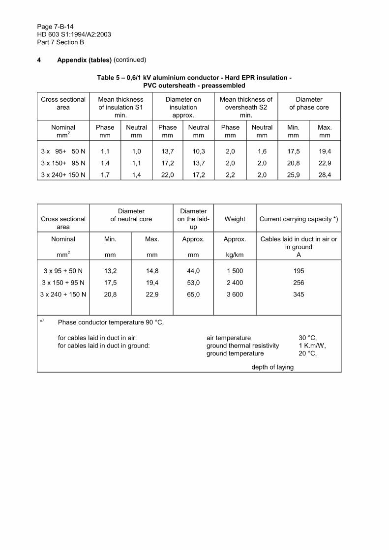
Page 7-B-14 HD 603 S1:1994/A2:2003 Part 7 Section B
4 Appendix (tables) (continued)
Table 5 0,6/1 kV aluminium conductor - Hard EPR insulation - PVC outersheath - preassembled
Cross sectional area
Mean thickness of insulation S1
min.
Diameter on insulation approx.
Mean thickness of oversheath S2
min.
Diameter of phase core
Nominal mm2
Phase mm
Neutral mm
Phase mm
Neutralmm
Phase mm
Neutralmm
Min. mm
Max. mm
3 x 95+ 50 N
3 x 150+ 95 N
3 x 240+ 150 N
1,1
1,4
1,7
1,0
1,1
1,4
13,7
17,2
22,0
10,3
13,7
17,2
2,0
2,0
2,2
1,6
2,0
2,0
17,5
20,8
25,9
19,4
22,9
28,4
Cross sectional
area
Diameter of neutral core
Diameter on the laid-
up
Weight
Current carrying capacity *)
Nominal
mm2
Min.
mm
Max.
mm
Approx.
mm
Approx.
kg/km
Cables laid in duct in air orin ground
A
3 x 95 + 50 N
3 x 150 + 95 N
3 x 240 + 150 N
13,2
17,5
20,8
14,8
19,4
22,9
44,0
53,0
65,0
1 500
2 400
3 600
195
256
345
*) Phase conductor temperature 90 °C, for cables laid in duct in air: air temperature 30 °C, for cables laid in duct in ground: ground thermal resistivity 1 K.m/W, ground temperature 20 °C,
depth of laying

Page 7-B-15 HD 603 S1:1994/A2:2003
Part 7 Section B
4 Appendix (tables) (continued)
Table 6 - 0,6/1 kV Copper conductor - hard EPR insulation - PVC outersheath
Cross sectional area
Mean thickness of insulation S1
Diameter on insulation
Mean thickness of sheath S2
Outer diameter
Nominal mm2
Min. mm
Approx. mm
Min. mm
Min. mm
Max. mm
1 x 6
1 x 16
1 x 25
1 x 50
1 x 95
1 x 150
1 x 240
0,7
0,7
0,9
1,0
1,1
1,4
1,7
4,1
6,5
8,2
10,1
13,6
17,0
22,0
1,4
1,4
1,6
1,6
2,0
2,0
2,2
6,8
8,9
10,9
13,2
17,5
20,8
25,9
8,1
10,3
12,5
14,8
19,4
22,9
28,4
Cross sectional
area
Weight
Current carrying capacity *)
Short-circuit
dynamics current
Nominal
mm2
Approx.
kg/km
Cables laid in air A
Cables laid in duct in air
A
Cables laid in ground
A
Cables laid in duct in ground
A
Max.
kA
1 x 6
1 x 16
1 x 25
1 x 50
1 x 95
1 x 150
1 x 240
110
220
320
550
1 050
1 500
2 400
61
112
148
221
342
454
610
48
89
117
175
269
359
481
68
119
156
218
322
410
545
54
95
125
175
258
328
436
-
-
-
-
-
-
-
*) Phase conductor temperature 90 °C, and moreover for cables laid in free air and in duct in air: air temperature 30 °C, for cables laid in ground and in duct in ground: ground thermal resistivity 1 K.m/W, ground temperature 20 °C, depth of laying 0

Page 7-B-16 HD 603 S1:1994/A2:2003 Part 7 Section B
4 Appendix (tables) (continued)
Table 7 - Packing and shipping lengths
Cable type (provisional designation)
Cross sectional area mm2
Coil length m
Shipping length m
UG7R
RG7R
RG7R
RG7R
RG7R
RG7R
RG7R
1 x 6
1 x 16
1 x 25
1 x 50
1 x 95
1 x 150
1 x 240
100
100
100
-
-
-
-
1 000
1 000
1 000
500
500
500
500
RG7RX
RG7RX
RG7RX
ARG7RX
ARG7RX
ARG7RX
3 x 50 + 25 N
3 x 95 + 50 N
3 x 150 + 95 N
3 x 95 + 50 N
3 x 150 + 95 N
3 x 240 + 150 N
500
500
500
500
500
500
NOTE Nominal and actual cable length
Unless otherwise agreed between customer and manufacturer, each delivery cable length shall not differ by more than +/- 3 % with respect to the nominal length indicated either in the order or in the relevant specification.
Lots of coils or drums of cable of the same type and nominal cross section type may contain up to 10 % of the cable lengths (rounded at the upper integer) shorter than the nominal length; if the lot contains no more than 10 coils or drums, two shorter cable lengths are admitted. In any case actual cable lengths shorter than 100 m are not admitted. If the total delivery length of shipping lot is not multiple of the normal length, the remaining cable length shall not be considered as a part of the shorter lengths.
The term lot indicates the whole cable lengths taken together to form a single delivering.
Drums and coils
Nominal cable lengths having weight not exceeding 35 kg are usually supplied as coiled while cable, lengths having greater weight are wound on drums. Unless otherwise agreed between customer and manufacturer, each coil or drum shall contain a single cable length.

Page 7-B-17 HD 603 S1:1994/A2:2003
Part 7 Section B
4 Appendix (tables) (concluded)
Cable lengths either coiled or wound on drum shall be protected in adequate manner to prevent damages and/or infringements.The inner diameter of coils or the inner diameter of drums wound shall not be less than 16 D; D being the outer cable diameter
Nominal data
Each drum or coil shall be identified by a plate, label or indelible inscription on which the following data shall be indicated:
a) manufacturer name or logo;
b) cable identification (cross section, nominal voltage, etc) (abbreviation are allowed with reference to the relevant standard);
c) possible indication to the standard the cable is referred to;
d) actual cable length.

Page 7-B-18 HD 603 S1:1994/A2:2003 Part 7 Section B
5 Guide to use
1 SCOPE
This Guide to use is valid for the 0,6/1 kV single-core and 4-cores preassembled type power distribution cables, according to HD 603 -7-B.
2 OBJECTS
The object of this Guide to use is to provide recommendations for the selection, storage, transportation and installation of the cables specified under Clause 1 Scope.
NOTE 1 Safety requirements as well as rule of installations are not considered in this Guide to use, as they are covered by the relevant national regulations and laws.
3 RECOMMENDATION FOR USE
3.1 Permissible applications
Cables according to HD 603-7-B may be used indoor, also in wet locations, and outdoor for fixed installations on wall and metallic structures and can be laid in ground in duct.
3.2 Highest permissible voltage
Cables rated at Uo/U = 0,6/1 kV are used in a.c. systems with a maximum voltage of 1,2 kV; they may be also used in d.c. systems having a rated operation voltage between conductors and earth not higher than 0,9 kV.
4 RECOMMENDATIONS FOR STORAGE AND TRANSPORT
4.1 Delivery
Cables shall be protected to avoid any damage during storage and transport. The radius of the drum core shall not be less than the minimum bending radius under controlled conditions given in 5.4 of this "Guide to use".
The distance between the outer cable layer in the filled drum and the protection lagging shall be sufficient to avoid damages of the cable.
Care shall be taken to avoid that nails, screws, etc. used in drum manufacturing or lagging fixing can cause damage to the cable.
4.2 Cable-end sealing
Cable-ends shall be sealed against water and moisture penetration during transport, storage and laying.
4.3 Transport
4.3.1 Drum transport
For the transport of cable filled drums only suitable carriers shall be used.
Cable filled drums shall be transported only with the drum axes in horizontal position. Any drum movement shall be avoided.
Loading and unloading shall be made by suitable devices to avoid damages of the cables and of the drums.
Page 7-B-19 HD 603 S1:1994/A2:2003
Part 7 Section B
5 Guide to use (continued)
Cable filled drums shall be rolled only on short distances over plain solid ground and only in the direction indicated on the cable drum. The cable ends have to be firmly fastened.
5 RECOMMENDATIONS FOR THE CABLE LAYING AND INSTALLATION
5.1 Laying and operating conditions
Cables shall be laid and operated in such a way not to impair their properties.
In this context the following items shall be taken into account:
a) service conditions, such as concentrations of cable installed, influence of external heat sources, soil thermal resistivity, soil drying, closed spaces like ducts, conduits and troughs, solar radiation, etc.;
b) chemical and electrochemical (stray currents) corrosion risks;
c) soil subsidence, vibrations, etc.;
d) method of laying and bedding material;
e) adverse external influence, e.g. oils, chemical solvents, acids, etc.;
f) potential attack by fauna and flora;
5.1.1 Installations in ducts, pipes and troughs.
The minimum diameter for the pipe and ducts shall be at least 1,4 times the cable outer diameter. This condition does not apply when the cables are laid instead of being pulled in the duct.
If single-core cables are laid through iron or magnetic steel pipes, the cables of all phases of the same electric system shall pass through the same pipe.
In the case of electric system having more than one cable per phase the currents sharing between the cables of the same phase have to be checked after installation to avoid a single cable overload.
5.1.2 Cables installed on walls or ceilings
When cables are installed horizontally on walls or ceilings, the approximate distance between brackets shall be 20 D, where D is the outer diameter, or 2 m, whichever is the lower.This distance also applies between points of support of cable racks or cable trays.
5.2 Minimum admissible installation temperature
Due to the presence of the thermoplastic sheaths, the minimum admissible temperature of cables during installation or handling is 0 °C.
5.3 Cable laying
Cables may be pulled either into ducts or directly into the cable trench by using appropriate pulling devices that ensure that the pulling force is evenly distributed on the cable conductors. The pulling force shall be permanently supervised during the cable laying operation to ensure that the maximum values will not be overpasses. Care should be taken to ensure that the cable outer sheath is not damaged during the laying operation.
5.3.1 Pulling by pulling-head
When cables are pulled by means of a pulling-head fixed to the conductors, the following maximum values for the pulling stresses are allowed:
a) for cables with copper conductors = 50 N / mm2
b) for cables with aluminium conductors = 30 N / mm2

Page 7-B-20 HD 603 S1:1994/A2:2003 Part 7 Section B
5 Guide to use (concluded)
5.3.2 Pulling by cable stocking
In case of cables with polymeric insulation and sheath, without a metallic covering, the pulling force can be transmitted by a pulling stocking via a frictional contact between stocking and cable.
The maximum pulling stresses reported in 5.3.1 are allowed, but with an upper limit of 10 kN.
5.3.3 Cable route
The cable route shall have well established curves and a sufficient number of cable rollers. Special attention shall be paid to the required minimum bending radii (see Subclause 5.4).
The pulling forces shall be permanently supervised during the pull-in procedure, and care shall be taken not to damage the cable surface during laying.
5.4 Bending radius
5.4.1 Minimum values
During installation the bending radius measured at the inner cable generatrix shall not fall below the following values:
- preassembled type cables: 18 times the diameter of the bigger single cable core.
In the case of laying operation with controlled bending, i.e. bending over a shape at a temperature not lower than 15 °C, the above specified bending radii may be halved.
6 OTHER RECOMMENDATIONS
Other recommendations are collected in the pictures in Annex 1.
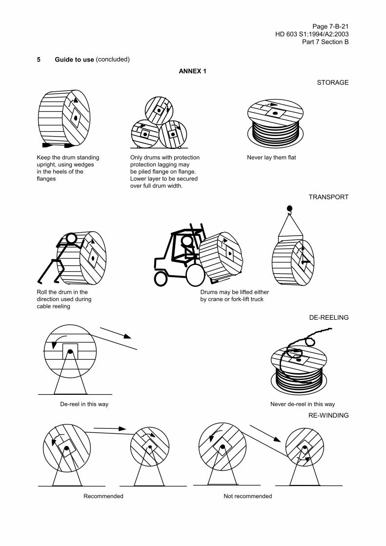
Page 7-B-21 HD 603 S1:1994/A2:2003
Part 7 Section B
5 Guide to use (concluded)
ANNEX 1 STORAGE
Keep the drum standing Only drums with protection Never lay them flat upright, using wedges protection lagging may in the heels of the be piled flange on flange. flanges Lower layer to be secured over full drum width.
TRANSPORT
Roll the drum in the Drums may be lifted either direction used during by crane or fork-lift truck cable reeling
DE-REELING
De-reel in this way Never de-reel in this way
RE-WINDING
Recommended Not recommended

Page 7-B-22 HD 603 S1:1994/A2:2003 Part 7 Section B
BLANK PAGE

Page 7-D-0 HD 603 S1:1994/A2:2003
Part 7 Section D
SECTION 7-D: CABLES WITH CONCENTRIC WAVEFORM NEUTRAL/EARTH (TYPE 7D)
Delete Section 7-D completely.
