terrestrial photogrammetric mapping of the neh-nar glacier in himalaya, india
TRANSCRIPT
ISPRS Journal of Photogrammetry and Remote Sensing, 44 ( 1989 ) 245-252 245 Elsevier Science Publishers B.V., Amsterdam - - Printed in The Netherlands
Terrestrial photogrammetric mapping of the Neh- Nat glacier in Himalaya, India
N.K. AGARWAL
Geological Survey o[ India, Lucknow 226 020, India
(Received 28 January 1989; revised and accepted 4 May 1989 }
ABSTRACT
Agarwal, N.K., 1989. Terrestrial photogrammetric mapping of the Neh-Nar glacier in Himalaya, India. ISPRS J. Photogramm. Remote Sensing, 44: 245-252.
Terrestrial photogrammetry holds distinct advantages over the conventional theodolite survey or aerial photogrammetry for glacier surveys, on account of inaccessibility of upper reaches of the glaciers and non-suitability of large-scale aerial photography for very high relief areas. The Neh- Nat glacier was mapped with a contour interval of 10 m utilising terrestrial photogrammetric techniques because no large-scale base map of the glacier was available for detailed glaciological studies. This glacier was selected under the International Hydrological Programme. Apart from topographic details various features of glaciological significance like transient snowline, accumu- lation and ablation zones, bergschrund, icefalls etc., were also mapped.
INTRODUCTION
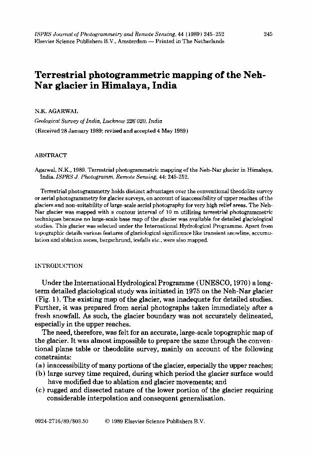
U n d e r the I n t e r n a t i o n a l Hydro logica l P r o g r a m m e ( U N E S C O , 1970) a long- t e r m deta i led glaciological s tudy was in i t i a ted in 1975 on the N e h - N a r glacier (Fig. 1 ). T h e exis t ing map of the glacier, was inadequa te for deta i led studies. Fu r the r , it was p r epa red f rom aerial pho tog raphs t a k e n immedia te ly a f te r a f resh snowfall . As such, t he glacier b o u n d a r y was no t accura te ly del ineated, especial ly in the uppe r reaches.
T h e need, therefore , was fel t for an accura te , large-scale topographic map of the glacier. I t was a lmos t impossible to p repa re the same t h ro u g h the conven- t ional p lane table or theodol i t e survey, ma in ly on accoun t of the following cons t ra in ts : (a) inaccessibil i ty of m a n y por t ions of the glacier, especially the upper reaches; (b) large survey t ime required, dur ing which per iod the glacier surface would
have modif ied due to ab la t ion and glacier movemen t s ; and (c) rugged a nd dissected na tu r e of the lower po r t ion of the glacier requir ing
cons iderable in t e rpo la t ion and consequen t general isat ion.
0924-2716/89/$03.50 © 1989 Elsevier Science Publishers B.V.
246 N.K. AGARWAL
Fig. 1. A UMK-100 photograph of the Neh-Nar Glacier.
The Geological Survey of India procured sophisticated terrestrial photo- grammetric equipment in 1978, primarily for glacier surveys. The technique was first applied in 1979 to prepare an accurate topographic map on a scale 1 : 5000 of the Neh-Nar glacier. Various features of glaciological interest were mapped simultaneously with topographic mapping.
The Neh-Nar glacier is about 3.8 km long. The glacier descends by about 1230 m from its head to the snout. The approach to the glacier requires an arduous 15-km-long trek along a mule track from the nearest road head.
INSTRUMENTS USED
( a ) A pair of 'Terrestrial Photogrammetric Cameras'-UMK- 100 of focal lengths 99.07 and 99.47 mm respectively, for taking stereopairs.
(b) A 2-m subtense bar for distance measurements between photo stations. (c) A theodolite of I s least count for survey of control points. (d) A precision coordinatograph for plotting the control points. (e) The analog stereo-plotter 'Topocart' for map preparation from stereopairs.

TERRESTRIAL PHOTOGRAMMETRIC MAPPING IN HIMALAYA 247
FIELD SURVEY
Six pairs of photo-stations were established on the higher elevations of the moraine ridges surrounding the lower portion of the glacier. The stereopairs were taken during the middle of August, 1979. The photo-stations were so se- lected that the intended coverage from each stereo-pair lies within a base/ distance ratio of 1/4 to 1/20 (Manual of Photogrammetry, 1966). A total of twenty control points were established in the area, out of which fourteen fixed control points were marked on suitable faces of the valley walls around the glacier and the remaining six were established on the body of the glacier. The control points were marked by painting white circles of appropriate dimen- sions with a cross mark in the centre for the theodolite survey. The coordinates of the control points were provided by the Survey of India party associated with the survey work of the glacier. The control points were so located that at least two of them form tie points in adjoining stereopairs.
The diameter of the floating mark of the 'Topocart ' is 0.06 mm. Accordingly, the diameter of a control point was so calculated that it resolves to be 0.06 mm on photo scale at that distance. Thus, diameter of control point-- 0.06 mm × photo scale photo scale = d/[ when, d--distance of control point, and f= focal length of camera.
Because of the small dimension of the control points (about 0.06 mm on the photo scale), these are not clearly visible to the naked eye on a single photo- graph. Therefore, the control points were marked and numbered on the pho- tographs, in the field itself, under a stereoscope.
The photographic cameras used require glass plate negatives called 'Topo- plates' for photography. But since the 'Topo-plates' were not readily available at the time of the survey the available sheet films of 160 ASA were used. These were cut to the appropriate size and mounted on ordinary glass plates with the help of cellotape. Obviously, it entailed some inaccuracies compared with 'Topo- plates'.
In remote, inaccessible areas it is not possible to have the facility of a pho- tographic laboratory. Therefore, an improvised, handy photo printing tech- nique was adopted. The standard ready made reagents were used for the pho- tographic work. Developing of negatives is a simple job, but the main problem comes in making prints which requires a controlled diffused light source. For making prints the photographic paper and the negative were placed between two ground glass plates, it was exposed by a light source from a three-cell torch whose transparent glass was again replaced by ground glass. After one or two trials it became possible to get sufficiently good quality prints.
In easier terrain, the stereopairs are generally taken by a single camera by interchanging the positions of the target and the camera. On glaciers the weather conditions fluctuate rather rapidly. Unmounting, packing and shifting
MA
P
OF
NE
H-N
AR
G
LA
CIE
Rj
&
~ /.
N~,.~
..i
"a''~
~_
c,,
(P
RE
PA
RE
D
FR
OM
T
ER
RE
ST
RIA
L
PH
OT
OG
RA
PH
S)
-:.>
C
O.T
OO
R
,.,E
WL
- ~
)///'
c~--
0
"l
~L
~-
~
Scal
e I.
16,0
00
(opp
rox)
\ -
x %
'
6 ,
: ".i
.\ \.
,~
.
~:,
af-
~
-2,_
T~'
; '
,:,
k~",
~t?'
~ o
-'°°-~ARBTRAR¥ z
~.o
) "~
Z22
;4;:
~
~°°
Q
~<
:,,
: /',.:),-'Y
~.?/%& ~"~
GLA
CIE
R
BO
UN
DA
RY
"~
°°~
,c
o
_ "~
Y~'
~ j
/ I
) 7.~-',2"~7~It~',i\ ;
"4"
~ ~
".2-
:-~/
~.
i /
~ )//
//I1
, ( (
I ~
, ,',
k i
..
..
..
..
~
"~2-
J'.
-'~
-'
.//f
; ~
( )
~ ~
' '
~,o,
- ,c
E F
AL<
*,T
. c
,,~
vA
ss
ES
~
oo
~
-,-
~
~.~,
,
! .~
,J
/{ -.,i,-
--~-"~
----m-
~ SUPR
AGLA
CIA
L C
HA
NN
EL/
IN
FER
RED
o
--~
5°°
m
~'~
'~'U
r"
fC_
")'~)
) j/l)
/) ~
~,'
, ,
LA
TE
RA
L
MO
RA
,NE
R,O
GE,
'~
<.o
o-
-'~
..;7
/A
S.
AR
P C
".T
'.OU
NO
EO
.
SCAR
P 70
0 "~
o
~
~-
-.
.
700
"~
(rr,.~
, ICE F
ACE
'~C
O
C
ON
TRO
L P
OIN
T
PH
OTO
S
TATI
ON
HIM
AL
AY
AS
~ IN
DIA
o Do
0
Fig.
2. M
ap (
d N
eh-N
ar G
laci
er,
Him
alay
as.
Indi
a.
OC
TERRESTRIAL PHOTOGRAMMETRIC MAPPING IN HIMALAYA 249
the camera from one station to other, through the rugged glaciated terrain, and resetting it on the second station would involve a large amount of time, thus resulting in variations in photographic conditions. Therefore, in the present case two cameras were used for taking the stereopairs at the same instant of time to avoid variations in the two photographic images.
PHOTOGRAMMETRIC PLOTTING
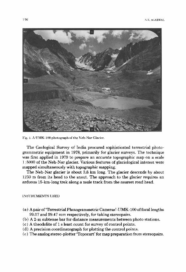
The control points were plotted with the help of the precision 'Coordinato- graph' attached with the 'Topocart'. The stereopairs were mounted on the 'To- pocart' and oriented and scaled with the help of these control points. Maps were prepared separately from five out of six stereopairs taken. The individual maps were combined to form the final map (Fig. 2). One of the stereopairs could not be well oriented on the Topocart and, therefore, was not used for map preparation, resulting in some gap areas in the lower central portions of the glacier. Further, the lower ablation zone of the glacier presented a highly dis- sected surface, because some areas along depressions formed dead areas and could not be mapped.
The 'Z' range of the Topocart lies between 70 mm and 320 mm. It defines the nearest and the farthest area from the camera station that can be mapped for a given scale of the three-dimensional model of the terrain. Generally, model scales between 2500 and 5000 were set for mapping. However, in case of two stereopairs, two different model scales were selected to cover near and distant areas. For nearer areas the above model scales were used and for farther areas the model scales of 8000 and 12,500 were used.
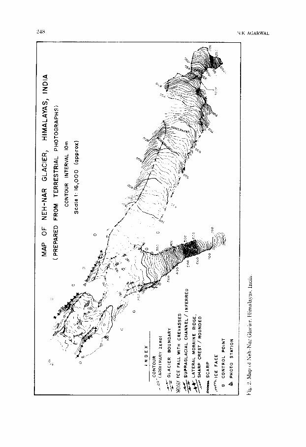
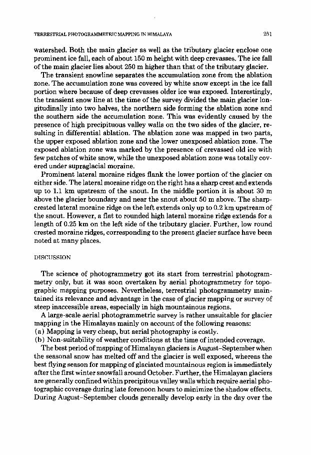
Photo-interpretation of the stereopairs helped in mapping various features of glaciological significance simultaneously with the topographic mapping. These include: transient snow line, accumulation and ablation zones, ice falls, supra-glacial channels, high and low lateral moraine ridges, bergschrund, etc. (Fig. 3). Wherever any feature was not clearly discernable in the stereopair, it has been shown as inferred or projected e.g. the glacier boundary in the lower accumulation zone of the main glacier was mostly covered under avalanche ice cones which had descended on the main glacier along a number of gullies oc- curring on the enclosing precipitous valley walls. Similarly, in the lower abla- tion zone the valleys of supraglacial channels were well exhibited but the chan- nels themselves were not visible and so the same have been marked as inferred.
MORPHOLOGY OF THE NEH-NAR GLACIER
The main glacier flows roughly towards the west-northwest over a length of 3.8 km and with an average width of 0.35 km. It is joined by a prominent trib- utary from the south in the lower middle portions. From the snout the glacier ascends in height by about 1230 m up to its head which reaches right up to the

GLA
CIO
LOG
AL
MA
P
OF
NE
H-N
AR
G
LAC
IER
IN
H
IMA
LAY
AS
j IN
DIA
~'6
O-
~-
( PR
EPAR
ED F
RO
M T
ERR
ESTR
IAL
PH
OTO
GR
AP
HS
)
/ •
" •
j~.~
Q
o S
cale
1:
16~0
00
(app
rox)
~,,.~
•
.~.~
..
--'.
.~
...:
-~,"
~,~
• °
• •
• •
~.
-- x-~
- TR
ANSI
ENT
SNOW
LINE
")'"
• ;."
" "
~' •
• .
• o
",~I
I. o.
.
• .-
. •
• ..
~ AC
CUM
ULAT
ION
ZONE
iA
s oN
~-L
~,.':
"i ."
"°.'S
'~.
. "
" '~
'~"
~ AB
LATI
ON Z
ONE
EXPO
SED
! ....
.. ;
~'i;°
" "
. °(
""
"
"''"
'° °°
" "~
°'~
A~L
AT
ION
~O
NE
~N
E×~
OS
ED
i ...
. "~
."
" .',
~'\;
( ''~
' "
' ""
:'"
,~E F
A,L
~,T~
CRE
VASS
ES
."
"L
""
"~
'4."
'.'
."
. " "
.",
\ B
ERII
SC
HR
UN
D
~')',
'i~;
' ~
"~*
"~
2. '
.'.
• .~
"~..
- "
• ".r
-* ~'~
" '
• "'
{ x~
]Yq
SH
AR
P C
RE
ST/
RO
UN
DE
D
~"
-" ."-
' ""
-L._
-~
~
7"~
- ."
"I~
" 'J
) .o
~ ;y
.~,
--
/LO
W
LATE
RA
L M
OR
AIN
E R
IDG
E R
OU
ND
E~ C
RE
S T
~''"
' r"
.~
''.'
'r
..~t"
SU
PRAG
LAC
IAL
CH
ANN
EL
..
"~y.
j
,'r~t
" IC
E F
AC
E
CREV
ASSE
S
Fig.
:~. G
taci
olog
al m
ap o
f N
eh-N
ar G
laci
er in
Him
alay
as,
Indi
a.
k~
TERRESTRIAL PHOTOGRAMMETRIC MAPPING IN HIMALAYA 251
watershed. Both the main glacier as well as the tributary glacier enclose one prominent ice fall, each of about 150 m height with deep crevasses. The ice fall of the main glacier lies about 250 m higher than that of the tributary glacier.
The transient snowline separates the accumulation zone from the ablation zone. The accumulation zone was covered by white snow except in the ice fall portion where because of deep crevasses older ice was exposed. Interestingly, the transient snow line at the time of the survey divided the main glacier lon- gitudinally into two halves, the northern side forming the ablation zone and the southern side the accumulation zone. This was evidently caused by the presence of high precipituous valley walls on the two sides of the glacier, re- sulting in differential ablation. The ablation zone was mapped in two parts, the upper exposed ablation zone and the lower unexposed ablation zone. The exposed ablation zone was marked by the presence of crevassed old ice with few patches of white snow, while the unexposed ablation zone was totally cov- ered under supraglacial moraine.
Prominent lateral moraine ridges flank the lower portion of the glacier on either side. The lateral moraine ridge on the right has a sharp crest and extends up to 1.1 km upstream of the snout. In the middle portion it is about 30 m above the glacier boundary and near the snout about 50 m above. The sharp- crested lateral moraine ridge on the left extends only up to 0.2 km upstream of the snout. However, a flat to rounded high lateral moraine ridge extends for a length of 0.25 km on the left side of the tributary glacier. Further, low round crested moraine ridges, corresponding to the present glacier surface have been noted at many places.
D I S C U S S I O N
The science of photogrammetry got its start from terrestrial photogram- metry only, but it was soon overtaken by aerial photogrammetry for topo- graphic mapping purposes. Nevertheless, terrestrial photogrammetry main- tained its relevance and advantage in the case of glacier mapping or survey of steep inaccessible areas, especially in high mountainous regions.
A large-scale aerial photogrammetric survey is rather unsuitable for glacier mapping in the Himalayas mainly on account of the following reasons: (a) Mapping is very cheap, but aerial photography is costly. (b) Non-suitability of weather conditions at the time of intended coverage.
The best period of mapping of Himalayan glaciers is August-September when the seasonal snow has melted off and the glacier is well exposed, whereas the best flying season for mapping of glaciated mountainous region is immediately after the first winter snowfall around October. Further, the Himalayan glaciers are generally confined within precipitous valley walls which require aerial pho- tographic coverage during late forenoon hours to minimize the shadow effects. During August-September clouds generally develop early in the day over the

252 N.K. AGARWAI
area, rendering a cloud-free aerial coverage during this period an uncertain proposition. On the contrary, terrestrial photogrammetry is very viable and unaffected by weather constraints. Conventional survey techniques, as already discussed, cannot provide an accurate topographic map of the glacier. Thus terrestrial photogrammetry is the most appropriate technique for mapping of the glaciers as is demonstrated by the results of the presented case study. How- ever, the technique has already been in use in Europe (Finsterwalder, 1938; Pillewizer, 1938). Of late, in India the technique of terrestrial photogrammetry has been applied to a variety of geoscientific investigations with significant advantages (Agarwal, 1986).
ACKNOWLEDGEMENT
The author records his sincere thanks to Shri C.P. Vohra and V.K. Raina, Geological Survey of India, under whose guidance the work has been carried out. Thanks are due to Sri B.B.K. Sastry, Geological Survey of India, Hyder- abad for valuable suggestions.
REFERENCES
Agarwal, N.K., 1986. Application of Stereo-terrestrial photogrammetric technique to varied geo- scientific investigation. In: Int. Archives of Photogrammetry and Sensing, Enschede-Nether- lands, Z6-VII, pp. 551-554.
Finsterwalder, R., 1938. Der heutige Stand der terrestrischen Photogrammetrie. Bildmessung I,u/~bildwesen, 13:2 7.
Manual of Photogrammetry, 1966, third edition, Vol. II. American Society oi l'hotogrammetry, Falls Church. VA, p. 948.
Pillewizer, W., 1938. Photogrammetrische Gletschertbrschung. Bildmessung Luftbildwesen, 13: 66 73.
UNESCO, 1970. Technical papers in hydrology. Paris-France.