terrestrial circuit management -...
TRANSCRIPT

497
C H A P T E R 8
Terrestrial Circuit Management
In an open CDMA Network, the trunks connecting theBase Station Controller (BSC) and Mobile Switching Center (MSC) need to be managed andmaintained by network operators to ensure that resources are used efficiently and reliably. Inmany cases, the MSC and BSC are physically separated and the terrestrial connections are estab-lished using leased T1 or E1 trunks. By effectively utilizing terrestrial resources, network opera-tors can reduce operating expenses and improve system reliability. CDGIOS specifies theprocedures and messaging, known as Terrestrial Circuit Management (TCM), to manage terres-trial resources effectively.
In addition to TCM, Terrestrial Facilities Management also includes the management oflinks, Link Sets, and Route Sets. Since these functions were already discussed in Chapter 2,“Signaling System 7 Basics,” on page 29, this chapter focuses on the messages and proceduresused to manage the states of terrestrial circuit resources shared between a BSC and MSC. Usu-ally the term terrestrial resource refers to individual 64 kbps DS0 timeslots that are dedicatedfor Pulse Code Modulation (PCM) voice or data services traffic. This chapter also includesdescriptions of the procedures and messages used to manage soft handoff resources between twoBSCs, which may consist of packetized data and virtual circuits. The overall goal of TCM is toensure that no hung resources exist and that all available circuits are utilized.
8.1 Terrestrial Circuit Management Overview
The TCM functions running on both the MSC and BSC utilize three procedures to managethe states of terrestrial circuits. Together, the three procedures provide the capability to reset thestates of one or more circuits or to prevent the use of individual circuits. The proceduresdescribed in this section apply only to the circuits that compose the A2-Interface; the circuits
498 Chapter 8 • Terrestrial Circuit Management
that are part of the A7-Interface are discussed separately in Section 8.5, “A7-Interface GlobalReset,” on page 528. The three TCM procedures are:
• Block and Unblock
• Reset Circuit
• Global Reset
The overall state of an individual terrestrial circuit is categorized by its usability state andtraffic state. The usability state of a circuit indicates whether the circuit has been blocked by theBSC. The BSC sends a Block message to the MSC after identifying that a circuit (or group ofcircuits) is out of service, indicating to the MSC that it should not request the circuit (or circuits)for future call setups. The BSC may block circuits due to equipment failure or as a result ofadministrative procedures. The BSC unblocks a previously blocked circuit by sending anUnblock message to the MSC. In addition to the usability state, each terrestrial circuit has asso-ciated with it a traffic state. The traffic state specifies whether the circuit is Busy with a call or ifit is Idle.
It is important to note that the usability state and traffic state of an individual circuit areindependent of each other. For example, a circuit may be Blocked and Busy, if the Block mes-sage was sent by the BSC for a circuit already in use. A circuit is said to be available only whenit is Unblocked and Idle. Both the MSC and BSC actively maintain the states of each individualterrestrial circuit.
Since usability and traffic state mismatches sometimes occur between the MSC and BSC,CDGIOS specifies two procedures for synchronizing the states. The Reset Circuit procedure isused to reset the state of an individual circuit and the Global Reset procedure is used to reset thestates of all circuits shared between the MSC and BSC. Although Reset Circuit and Global Resetmessages are sent by both the MSC and BSC, Block and Unblock messages are sent only by theBSC.
Each terrestrial circuit is assigned a logical identifier known as its Circuit Identity Code(CIC). Both the MSC and BSC use this logical identifier to reference a particular circuit. Section8.1.5, “Spans and Circuits Identity Assignment,” on page 502 describes how CIC values arecoded in A-Interface messages.
8.1.1 Block and Unblock
The usability state of a CIC can be changed by the BSC through the use of the Block orUnblock procedures. Upon determining that a CIC should no longer be used, the BSC performsa local administrative procedure to designate the CIC as blocked, then sends an A-InterfaceBlock messages to the MSC, informing the MSC of the unavailability of the circuit. The Blockmessage may specify an individual CIC or a group of CICs to be blocked by the MSC. Afterreceiving the Block message, the MSC designates the CIC as blocked and prevents it from being
Terrestrial Circuit Management Overview 499
used in future call setups by removing it from its available CIC list. The MSC acknowledgeseach received Block message with a Block Acknowledge message.
The BSC typically blocks CICs when it determines that a previously configured range ofCICs must be taken out of service for maintenance reasons or because of a failure. The MSCmay also block CICs that it determines should no longer be used. Beause the MSC has controlover which CICs are allocated for calls, no messaging is required to inform the BSC of MSC-blocked CICs. In the case of MSC blocked CIC’s, the MSC simply does not allocate the locallyblocked CICs when sending an Assignment Request message to the BSC.
Upon determining that a previously blocked CIC should be made available for use, theBSC sends an Unblock message to the MSC, specifying the CIC (or group of CICs) to bereturned to service. The MSC acknowledges each received Unblock message with an UnblockAcknowledge message. As is discussed in Section 8.3, “Reset Circuits,” on page 510 and Sec-tion 8.4, “Global System Reset,” on page 516, the states of a CIC (or group of CICs) can also bechanged to the Unblocked and Idle state through the use of the Reset Circuit or Global Resetmessages.
To prevent inconsistencies in circuit states, the TCM functions at both the BSC and MSCwait for the remote end to acknowledge TCM messages before changing the state of a circuits.For example, if the BSC sends an Unblock message for a CIC and does not receive an acknowl-edgment from the MSC within a specified period of time, the CIC remains Blocked.
Since Block and Unblock messages are not associated with a Signaling Connection Con-trol Part (SCCP) connection, the messages are sent as connectionless SCCP Unit Data (SCCP-UDT) class 0 messages. CDGIOS allows the BSC to send Block and Unblock messages for eachCIC or to group of multiple CICs in a single message.
The Block and Unblock procedures and messages are discussed further in Section 8.2,“Blocks and Unblocks,” on page 503.
8.1.2 Reset Circuit
The MSC or BSC performs the Reset Circuit procedure when a failure affecting part of theequipment occurs or when requested by network operators through Operations and Mainenance(OA&M) actions. A Reset Circuit message is also sent by the MSC or BSC whenever eitherentity detects that one or more CIC’s have been idled, due to an abnormal SCCP release.
Reset Circuit is typically triggered when an SCCP connection associated with a call is lostunexpectedly. This is known as an abnormal SCCP release and occurs when one node unexpect-edly sends an SCCP Released (SCCP-RLSD) message. The receiving node responds with theSCCP Release Complete (SCCP-RLC) and requests the remote end to idle the associated terres-trial circuit by sending a Reset Circuit message.
The Reset Circuit message is sent by the entity at the receiving end of an abnormal SCCPrelease to request the remote node to idle one or more CICs. Upon receiving a Reset Circuit, theremote end responds with a Reset Circuit Acknowledge message if it is able to idle the specifiedCIC (or group of CICs). If the Reset Circuit is initiated by the MSC and some of the specified

500 Chapter 8 • Terrestrial Circuit Management
circuits are blocked at the BSC, the BSC responds with a Block message in addition to the ResetCircuit Acknowledge message.
8.1.3 Global Reset
The Global Reset procedure is used by the BSC and MSC to bring the remote node into aknown state after a global failure occurs, during initialization, and when requested by the net-work operator through the use of OA&M actions. Unlike the Block and Reset Circuit messages,which are sent for an individual CIC or group of CICs, the Reset message applies to all CICs.After receiving a Reset message, the remote node releases all affected calls and all affected callreferences. After placing its CICs in idle mode and upon expiry of a guard timer, a ResetAcknowledge message is sent to indicate the receipt of the Reset message.
8.1.4 Terrestrial Circuit States Transition
Figure 8-1 illustrates the states and state transitions associated with CICs at the BSC andMSC. Both the MSC and BSC maintain the current state of all configured CICs and utilize A-Interface messages to notify the remote end of state changes. Reset Circuit and Global Resetmessages are used by both the MSC and BSC to reset CICs after an abnormal event has occurredor during initialization. The BSC may also use Block and Unblock messages to inform the MSCof changes in CIC availability at the BSC. Only CICs in the Unblocked and Idle state are avail-able for use.
Global Reset The MSC or BSC may send a Reset message to the remote end to syn-chronize the states of the configured CICs. Upon receiving a Reset message from the BSC, theMSC releases all existing call references and idles the CICs associated with the BSC. Afteridling the CICs, the MSC may locally block CICs that it determines should not be used or whenit is directed to block them by the BSC.
The BSC, upon receiving a Reset message from the MSC, places all CICs in theUnblocked and Idle state. The BSC may then send block messages to prevent the MSC fromallocating CICs that the BSC determines are out of service. For example, prior to receiving aReset message from the MSC, the state of a CIC at the BSC may be Blocked and Busy. Afterreceiving a Reset message, the BSC transitions the CIC to the Unblocked and Idle state, thenexecutes the procedure to block the CIC (if conditions still exist that require the CIC to beblocked).
Assignment Request/ Assignment Complete Although the BSC may requestthat a particular CIC be used for a call attempt, the MSC is responsible for specifying the terres-trial circuit used for a call. Upon sending an Assignment Request message to the BSC, the MSCtransitions the state of the requested CIC from Unblocked and Idle to Unblocked and Busy. TheBSC, after setting up the radio link and seizing the terrestrial circuit specified in the AssignmentRequest message, transitions the CIC state at the BSC to Unblocked and Busy, then sends anAssignment Complete.

Terrestrial Circuit Management Overview 501
Clear Command As discussed earlier, either the BSC or MSC may initiate call clear-ing. BSC-initiated call clearing begins with the BSC sending a Clear Request message, whichprompts the MSC to respond with a Clear Command message. Upon sending the Clear Com-mand message to the BSC, the MSC releases call resources, then returns the previously allocatedCIC to the Unblocked and Idle state. After receiving the Clear Command message, the BSCreleases associated call resources, including Idling the CIC. As shown in Figure 8-1, it is alsopossible for a circuit to be blocked during a call, resulting in a Blocked and Busy state. TheBlocked and Busy CIC is placed in the Blocked and Idle state after call clearing has occurred.
Reset Circuit When the BSC or MSC performs a Reset Circuit action, the CIC (orgroup of CICs) is transitioned from its current state to the Unblocked and Idle state. If the CIC(or group of CICs) specified in the Reset Circuit initiated by the MSC is blocked at the BSC, theBSC responds with a Block message, and the circuit is transitioned to the Blocked and Idle state.
Block When initiating the block procedure for a CIC, the BSC sends a Block messageto the remote end and transitions the state of the circuit from Unblocked to Blocked, regardlessof whether the circuit is Busy or Idle. The MSC, upon receiving the Block message, also placesthe CIC in the Blocked state.
Figure 8-1 Terrestrial Circuit States and State Transitions
Blocked, Busy
Block (BSC)
Global Reset (BSC/MSC) Reset Circuit (BSC) Unblock (BSC)
Assignment Request (MSC) Assignment Complete (BSC)
Global Reset (BSC/MSC)Reset Circuit (BSC/MSC)Clear Command (MSC)
Block (BSC)
Unblock (BSC)
Clear Command (MSC)
Only CICs in this state can beallocated for call processing.
The MSC may locally blockCICs that it determines shouldnot be allocated. No messagingis required to inform BSC.
Global Reset (BSC/MSC)Reset Circuit (BSC)
Blocked, Idle
UnBlocked, Idle
UnBlocked, Busy

502 Chapter 8 • Terrestrial Circuit Management
Unblock When the BSC determines that a CIC should be unblocked, it sends the MSCan Unblock message and places the CIC in the Unblocked state. The MSC, upon receiving theUnblock message, also places the circuit in the Unblock state.
A-Interface TCM messages such as Blocks, Unblocks, Reset Circuit, and Reset, are usedto inform the remote end of local state change and to execute the required actions to make theremote and local states consistent. As was mentioned earlier, if A-Interface TCM messages arenot acknowledged, the local end takes appropriate actions to ensure state consistency. For exam-ple, if the MSC does not acknowledge an Unblock message sent by the BSC, the CIC remainsblocked at the BSC.
8.1.5 Spans and Circuits Identity Assignment
Figure 8-2 illustrates voice trunks connecting the MSC and BSC. Recall that the A-Inter-face contains an A1-Interface used for signaling and an A2-Interface used to carry voice trafficbetween the MSC and BSC. The A2-Interface is comprised of CICs configured at both the MSCand BSC. Each CIC is associated with a particular timeslot on a trunk (sometimes referred to asspans) connecting the MSC and BSC. In order for the MSC and BSC to successfully coordinate
Figure 8-2 Example of Spans and Circuits configuration at BSC and MSC
MSC
PC = 7-13-64SSN = 252
PC = 128-78-4SSN = 252
PC = 11-22-68SSN = 252
BSC 2
Span1
Span2
BSC 1
Span3
Span4
Span5
Span6
CIC parameter IE sent in Assignment Request is of the form:
x x x x x x x x
x x x y y y y y
- The 11 bits designated for PCM mux (high and low)are sometimes referred to as span id
time slot (5 bits)
Examples:
- Span id = 0, Timeslot = 7 maps to CIC code = 7bitmap: 00000000 00000111 - Span id = 6, Timeslot = 20 maps to CIC code = 212bitmap: 00000000 11010100
PCM mux high
PCM muxlow
The CIC codes configured at theMSC and BSC must match.
Available CIC Lists
------------------------
BSC 1
------------------------
BSC 2
Blocks and Unblocks 503
the allocation of terrestrial resources for a call, logical CIC assignments at both the MSC andBSC must match. A mismatch in CIC assignments will result in a call without voice. For exam-ple, a CIC mismatch may cause the BSC to transmit PCM voice frames on a timeslot differentthan the MSC is expecting, and the MSC will be unable to connect the mobile subscriber to theintended land or mobile party.
A-Interface messages use a 16-bit field contained in the Circuit Identity Code or CircuitIdentity Code Extension IE to identify CICs. The 16-bit CIC field contains an 11-bit field thatidentifies the PCM identity of the trunk (sometimes called the Logical Span Id) and a 5-bit fieldthat specifies the timeslot. Figure 8-2 shows two examples of how CIC codes are computed fromthe logical span Id and timeslot.
To prevent invalid CIC assignments, any CICs configured at the MSC that are not config-ured at the BSC must be locally blocked at the MSC and removed from the MSC’s available CIClist. If the MSC requests an invalid CIC from the BSC in the Assignment Request message, dueto an error condition or invalid configuration, the BSC responds with an Assignment Failuremessage to the MSC.
8.2 Blocks and Unblocks
This section presents the call flow and messages for both the Block and Unblock proce-dures. Block and Unblock messages always originate from the BSC and are used to notify theMSC of changes in CIC states detected by the BSC. The MSC may also block circuits locally,however, because the MSC can prevent CICs from being used by simply removing the CICsfrom its available CIC list, no A-Interface messaging is required.
8.2.1 Block Call Flow
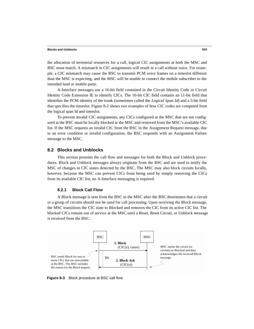
A Block message is sent from the BSC to the MSC after the BSC determines that a circuitor a group of circuits should not be used for call processing. Upon receiving the Block message,the MSC transitions the CIC state to Blocked and removes the CIC from its active CIC list. Theblocked CICs remain out of service at the MSC until a Reset, Reset Circuit, or Unblock messageis received from the BSC.
Figure 8-3 Block procedure at BSC call flow
BSC
1. Block (CIC(s), cause)
2. Block Ack (CIC(s))
MSC
T1BSC sends Block for one ormore CICs that are unavailableat the BSC. The BSC includesthe reason for the Block request.
MSC marks the circuit (orcircuits) as Blocked and thenacknowledges the received Blockmessage.

504 Chapter 8 • Terrestrial Circuit Management
Figure 8-3 shows the call flow for the Block procedure. The BSC initiates the blocking ofone or more CICs by sending a Block message to the MSC. The Block message also contains acause value that specifies the reason for the block request.
Upon receipt of the Block message, the MSC marks the circuit (or circuits) as blocked andacknowledges the BSC with a Block acknowledge message.
1. Block (A-Interface):
Upon determining that a terrestrial circuit (or group of circuits) should be blocked, theBSC marks the CIC (or group of CICs) as blocked and sends a Block message to the MSC.The BSC starts timer T1 to wait for a Block Acknowledge message from the MSC.
In addition to specifying the one or more CICs to be blocked, the Block message also con-tains the reason for issuing the block request. CDGIOS allowable cause values are OA&Mintervention, no radio resource available, and equipment failure.
2. Block Ack (A-Interface):
Upon receiving a Block message from the BSC, the MSC locally blocks the specifiedCICs and sends a Block Acknowledge message to the BSC, indicating to the BSC that theCICs have been blocked at the MSC. If the Block message received from the BSC speci-fies a group of circuits to be blocked and the MSC was unable to block all of the CICs, theMSC has the flexibility of specifying which circuits were successfully blocked in theBlock Acknowledge message.
CICs blocked by the MSC in response to a Block message from the BSC remain in theblocked state until the BSC sends an Unblock message or Reset Circuit message or if theMSC initiates a Global Reset.
If a Block message is received by the MSC for a CIC that is already allocated to a call, thecall is not dropped. In this case, the MSC sends a Block Acknowledge message immedi-ately to the BSC and waits for normal call clearing before designating the CIC as blocked.
The BSC stops timer T1 upon receipt of the Block Acknowledge message from the MSC.If T1 expires before a Block Acknowledge message is received, the BSC resends theBlock message to the MSC once more and marks the circuit (or group of circuits) asblocked, regardless of whether it receives an acknowledgment from the MSC. If the MSCdoes not respond with a Block Acknowledge message, it is possible that a CIC state mis-match may exist and that the MSC will include the BSC blocked CIC in an AssignmentRequest message. If this occurs, the BSC responds to the Assignment Request with anAssignment Failure message with cause value “terrestrial resource unavailable.” The BSCsubsequently sends a Block message to the MSC with the cause value set to “no radioresource available.”

Blocks and Unblocks 505
8.2.2 Unblock Call Flow
Unblock messages are sent from the BSC to the MSC once the BSC determines that a pre-viously blocked circuit (or a group of circuits) is available for service. Upon receiving anUnblock message, the MSC returns the specified CIC(s) to service and updates its available CIClist.
Figure 8-4 shows the call flow for the Unblock procedure. After determining that a CICshould be made available for service, the BSC sends an Unblock message to the MSC and startstimer T1.
Upon receipt of the Unblock message, the MSC marks the circuit as unblocked and sendsthe BSC an Unblock Acknowledge message. Detail descriptions of the individual call flowstages follow Figure 8-4.
1. Unblock (A-Interface):
The BSC requests that the MSC unblocks one or more previously blocked terrestrial cir-cuits by sending an Unblock message over the A-Interface. Upon sending the Unblockrequest, the BSC marks one or more CICs specified in the message as unblocked and startstimer T1 to wait for an Unblock Acknowledge.
2. Unblock Ack (A-Interface):
Upon receipt of the Unblock message, the MSC marks the previously blocked CIC(s) asUnblocked and sends an Unblock Acknowledge message to the BSC. The UnblockAcknowledge message identifies the one or more CICs unblocked at the MSC. If a groupof circuits is specified by the BSC in the Unblock message, the MSC may acknowledgeindividual circuits or the entire group in the Unblock Acknowledge message. This pro-vides the MSC with the flexibility to indicate which of the requested CICs were success-fully unblocked. The unblocked CIC(s) may then be allocated by the MSC for trafficservices in future Assignment Request messages.
The BSC stops timer T1 upon receipt of the Unblock Acknowledge message. If T1 expiresbefore an Unblock Acknowledge message is received at the BSC, the BSC resends the
Figure 8-4 Unblock procedure at BSC call flow
BSC1. Unblock (CIC(s))
2. Unblock Ack (CIC(s))
MSC
T1
BSC sends Unblock messagefor previously blocked CIC(s)which are now available.
MSC marks the circuit asUnblocked andacknowledges the BSC.
If BSC does not receive theUnblock Ack from the MSC,it resends Unblock once more.Upon 2nd expiry, the CIC(s)remains Blocked at the BSC.
506 Chapter 8 • Terrestrial Circuit Management
Unblock message a second and final time. If no acknowledgment is received for the sec-ond unblock attempt, the CIC remains blocked at the BSC.
8.2.3 Blocks and Unblocks Messages
The following sections contain descriptions of the A-Interface messages that are used inthe Block and Unblock procedures.
8.2.3.1 BlockThe Block message (Table 8-1) is sent by the BSC to request the MSC to block one or
more terrestrial circuit or a group of terrestrial circuits. It is a BSMAP message that is sent as aconnectionless SCCP Unit Data (SCCP-UDT) message type.
The first parameter following the message type Information Element (IE) is the mandatoryCircuit Identity Code IE, which specifies the CIC to be blocked at the MSC.
The mandatory Cause IE contains the reason why the BSC is requesting the MSC to blockthe specified CIC. CDGIOS-allowable cause values are "operations and maintenance," "equip-ment failure," and “no radio resource available.”
The optional Circuit Group IE provides a means of specifying a group of CICs to beblocked and avoids the need to send individual Block messages for each CIC. The BSC may usethe Circuit Group IE in one of several ways.
The BSC may use the Circuit Group IE to specify an inclusive group of CICs to beblocked by setting the 1-bit “Inclusive” field to 1. In this case, the “Count” octet specifies thenumber of CICs to be blocked and is followed by the “First CIC” in the group. Upon receivingthe Block message, the MSC blocks all CICs in the range [1st CIC, 1st CIC + count –1].
The second way that the BSC may use the Circuit Group IE is to specify a range of CICs,then selectively choose CICs within that range to be blocked. In this case, the 1-bit “Inclusive”field is set to zero and a Circuit Bitmap field that indicates which CICs in the group should beblocked is also included. For example, if the first two and the last four CICs of a 16-CIC groupmust be blocked, the Circuit Bitmap field is set to:
1111 00000000 0011As with the inclusive method, the CIC group is specified using the Count and First CIC
fields.The final way that the BSC may use the Circuit Group IE to specify a range of CICs to be
blocked is to set “All Circuits” field to 1. In this case, all CICs shared between the MSC andBSC are blocked.
It is possible to include multiple instances of the Circuit Group IE. However, the First CICfield in the first instance must match the mandatory Circuit Identity Code IE in the same mes-sage.

Blocks and Unblocks 507
• BSAP Message Type: BSMAP• SCCP Message Type: SCCP-Unit Data (UDT)• Direction: BSC → MSC
8.2.3.2 Block AcknowledgeThe Block Acknowledge message is sent from the MSC to the BSC to acknowledge the
blocking of a terrestrial circuit specified in a previously received Block message (Table 8-2).The Block Acknowledge message is a BSMAP message that is sent as a connectionless SCCPUnit Data (SCCP-UDT) message type.
The first parameter following the message type IE is the mandatory Circuit Identity CodeIE, which specifies the CIC to be blocked at the MSC.
The optional Circuit Group IE provides a means of specifying a group of CICs blocked bythe MSC and avoids the need to send individual Block Acknowledge messages for each CIC.
Table 8-1 Block Message (CDGIOS 6.1.6.2)
BitMap Param IE #Oct Range Type IOS Ref
0000 0000 (00H)LLLL LLLL
BSMAP header 2 Msg Discrim. = 0 (BSMAP)
L = BSMAP msg length
M 6.2.2.1
6.2.2.3
0100 0000 (40H) Msg Type 1 Block Msg M 6.2.2.4
0000 0001 (01H)mmmm mmmmmmmt tttt
Circuit Identity Code
3 m = spanid
t = timeslot
M 6.2.2.22
0000 0100 (04H)LLLL LLLL0ccc cccc
Cause 3 L = 01H, c = cause
07H—OA&M intervention
20H—equipment failure
21H—no radio resource avail
M 6.2.2.19
0001 1001 (19H)LLLL LLLL0000 00AIcccc ccccffff ffffffff ffffbbbb bbbbbbbb bbbb……bbbb bbbB
Circuit Group Var-iable
L = length
A = All circuits indicator (1,0)
I = Inclusive indicator (1,0)
c = number of CICs included
f = 1st CIC value (span,TS)
b = bitmap of CICs included
(1—this CIC included)
B = bitmap of 1st CIC = 1
O,C 6.2.2.148

508 Chapter 8 • Terrestrial Circuit Management
For more information about how this parameter is used please refer to the description providedfor the Block message in Section 8.2.3.1, “Block,” on pag e506.
• BSAP Message Type: BSMAP• SCCP Message Type: SCCP-Unit Data (UDT)• Direction: BSC ← MSC
8.2.3.3 Unblock The Unblock message (Table 8-3) is sent from the BSC to the MSC to unblock one or
more specified terrestrial circuits. This BSMAP message is sent as a connectionless SCCP-UDTmessage type.
The first parameter following the message type IE is the mandatory Circuit Identity CodeIE, which specifies the CIC to be unblocked at the MSC.
The optional Circuit Group IE provides a means of specifying a group of CICs to beunblocked and avoids the need to send individual Unblock messages for each CIC. For moreinformation about how this parameter is used please refer to the description provided for theBlock message in Section 8.2.3.1, “Block,” on page506.
• BSAP Message Type: BSMAP• SCCP Message Type: SCCP-Unit Data (UDT)• Direction: BSC → MSC
Table 8-2 Block Acknowledge Message (CDGIOS 6.1.6.3)
BitMap Param IE #Oct Range Type IOS Ref
0000 0000 (00H)LLLL LLLL
BSMAP header
2 Msg Discrim. = 0 (BSMAP)
L = BSMAP msg length
M 6.2.2.1
6.2.2.3
0100 0001 (41H) Msg Type 1 Block Ack Msg M 6.2.2.4
0000 0001 (01H).........
Circuit Identity Code
3 Same as element in Tabl e8-1, Block message
M 6.2.2.22
0001 1001 (19H)……
Circuit Group Var-iable
Same as element in Tabl e8-1, Block message
O,C 6.2.2.148

Blocks and Unblocks 509
8.2.3.4 Unblock AcknowledgeThe Unblock Acknowledge (Table 8-4) message is sent from the MSC to the BSC to
acknowledge the unblocking of a terrestrial circuit specified in a previously specified Unblockmessage. This BSMAP message is sent as a connectionless SCCP-UDT message type.
The first parameter following the message type IE is the mandatory Circuit Identity CodeIE, which specifies the CIC unblocked at the MSC.
The optional Circuit Group IE provides a means of specifying a group of CICs unblockedby the MSC and avoids the need to send individual Unblock Acknowledge messages for eachCIC. For more information about how this parameter is used please refer to the description pro-vided for the Block message in Section 8.2.3.1, “Block,” on pag e506.
• BSAP Message Type: BSMAP• SCCP Message Type: SCCP-Unit Data (UDT)• Direction: BSC ← MSC
Table 8-3 Unblock Message (CDGIOS 6.1.6.4)
BitMap Param IE #Oct Range Type IOS Ref
0000 0000 (00H)LLLL LLLL
BSMAP header 2 Msg Discrim. = 0 (BSMAP)
L = BSMAP msg length
M 6.2.2.1
6.2.2.3
0100 0010 (42H) Msg Type 1 Unblock Msg M 6.2.2.4
0000 0001 (01H).......
Circuit Iden-tity Code
3 Same as element in Table 8-1, Block message
M 6.2.2.22
0001 1001 (19H)……
Circuit Group Var-iable
Same as element in Table 8-1, Block message
O,C 6.2.2.148
Table 8-4 Unblock Acknowledge Message (CDGIOS 6.1.6.5)
BitMap Param IE #Oct Range Type IOS Ref
0000 0000 (00H)LLLL LLLL
BSMAP header 2 Msg Discrim. = 0 (BSMAP)
L = BSMAP msg length
M 6.2.2.1
6.2.2.3
0100 0011 (43H) Msg Type 1 Unblock Ack Msg M 6.2.2.4

510 Chapter 8 • Terrestrial Circuit Management
8.3 Reset Circuits
The Reset Circuit procedure may be initiated by either the BSC or the MSC and is invokedwhen a failure affecting part of the equipment occurs or when requested by network operatorsthrough OA&M actions. The MSC or BSC sends a Reset Circuit message after either entitydetects that a CIC has been idled, due to an abnormal SCCP release.
8.3.1 Reset Circuit at BSC Call Flow
Figure 8-5 illustrates the Reset Circuit message flow when the Reset Circuit action is initi-ated by the BSC. Upon determining that the state of one or more circuits needs to be reset, theBSC sends a Reset Circuit message to the MSC and starts timer T12. Upon receipt of the ResetCircuit message, the MSC idles the CIC(s) specified in the received message and sends the BSCa Reset Circuit Acknowledge.
1. Reset Circuit (A-Interface):
The BSC initiates a Reset Circuit action after determining that one or more circuits havebeen idled as a result of an abnormal SCCP release. The BSC sends a Reset Circuit mes-sage to the MSC, requesting that the circuit(s) be idled. The message includes a causevalue that indicates the reason for the reset. After sending the Reset Circuit message, theBSC starts timer T12.
0000 0001 (01H).......
Circuit Identity Code
3 Same as element in Tabl e8-1, Block message
M 6.2.2.22
0001 1001 (19H)……
Circuit Group Var-iable
Same as element in Tabl e8-1, Block message
O,C 6.2.2.148
Figure 8-5 Reset Circuit at BSC call flow
Table 8-4 Unblock Acknowledge Message (CDGIOS 6.1.6.5) (Continued)
BitMap Param IE #Oct Range Type IOS Ref
BSC1. Reset Circuit (CIC(s), cause)
2. Reset Circuit Ack (CIC(s))
MSC
T12
The BSC idles one or more CICsand sends Reset Circuit messageto the MSC. The BSC includesthe reason for Reset Circuit in theCause value.
The MSC idles the CIC(s)and acknowledges the BSC.
Reset Circuits 511
The MSC, upon receipt of the Reset Circuit message, clears any affected calls and idlesthe CIC(s).
2. Reset Circuit Ack (A-Interface):
The Reset Circuit Acknowledge message is sent from the MSC to the BSC after idling theCICs specified in the previously received Reset Circuit message. Any specified CICs thatwere in the blocked state prior to receiving the Reset Circuit message are transitioned tothe unblocked state.
If an existing call is using a CIC specified in the Reset Circuit message received from theBSC, the call is cleared, and the CIC is returned to the Unblocked and Idle state.
The BSC stops timer T12 upon receipt of the Reset Circuit Acknowledge message fromthe MSC. If T12 expires before the Reset Circuit Acknowledge message is received, theBSC resends the Reset Circuit message. CDGIOS specifies that the Reset Circuit messagebe sent no more than three times.
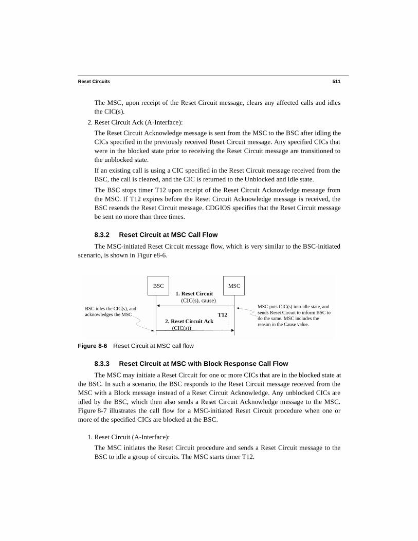
8.3.2 Reset Circuit at MSC Call Flow
The MSC-initiated Reset Circuit message flow, which is very similar to the BSC-initiatedscenario, is shown in Figur e8-6.
8.3.3 Reset Circuit at MSC with Block Response Call Flow
The MSC may initiate a Reset Circuit for one or more CICs that are in the blocked state atthe BSC. In such a scenario, the BSC responds to the Reset Circuit message received from theMSC with a Block message instead of a Reset Circuit Acknowledge. Any unblocked CICs areidled by the BSC, which then also sends a Reset Circuit Acknowledge message to the MSC.Figure 8-7 illustrates the call flow for a MSC-initiated Reset Circuit procedure when one ormore of the specified CICs are blocked at the BSC.
1. Reset Circuit (A-Interface):
The MSC initiates the Reset Circuit procedure and sends a Reset Circuit message to theBSC to idle a group of circuits. The MSC starts timer T12.
Figure 8-6 Reset Circuit at MSC call flow
BSC1. Reset Circuit (CIC(s), cause)
2. Reset Circuit Ack (CIC(s))
MSC
T12
MSC puts CIC(s) into idle state, andsends Reset Circuit to inform BSC todo the same. MSC includes thereason in the Cause value.
BSC idles the CIC(s), andacknowledges the MSC

512 Chapter 8 • Terrestrial Circuit Management
2. Block (A-Interface):
The BSC determines that one or more CICs specified by the MSC in the Reset Circuitmessage are in the blocked state. The BSC then responds to the MSC with a Block mes-sage for the blocked CICs, indicating the reason for the blocking. The BSC starts TimerT1. The MSC stops timer T12 upon receipt of the Block message.
3. Reset Circuit Ack (A-Interface):
The BSC idles the remaining CICs specified in the Reset Circuit message, then informsthe MSC of the action by sending a Reset Circuit Acknowledge message.
4. Block Ack (CICs) (A-Interface):
Upon receipt of the Block message, the MSC blocks the specified CICs and sends one ormore Block Acknowledge messages to the BSC. The BSC stops timer T1 upon receipt ofthe Block Acknowledge message.
8.3.4 Reset Circuit Messages
The following sections provide detail descriptions of the A-Interface messages used in theReset Circuit procedure.
8.3.4.1 Reset CircuitThe Reset Circuit message (Table 8-5) is a BSMAP message sent by either the BSC or
MSC to idle one or more terrestrial circuits. The message is sent as a connectionless SCCP-UDT message type.
The mandatory Circuit Identity Code IE specifies the CIC to be reset (idled) by the remotenode.
Figure 8-7 Reset Circuit at MSC with Block Response call flow
BSC
1. Reset Circuit (CICs, cause)
2. Block (CICs, cause)
MSC
T12MSC puts CICs into idle state andsends Reset Circuit message torequest the BSC to do the same.The MSC includes the reason forthe reset action in the Cause value.
BSC responds with Blockmessage for CICs whichwere previously in theblocked state.
4. Block Ack (CICs)T1
MSC marks the CICs from theBlock message as Blocked andsends an acknowledgment tothe BSC.
3. Reset Circuit Ack (CICs)
Reset Circuit Acks are sent forCICs that were successfullyunblocked and idled.

Reset Circuits 513
CDGIOS specifies that the mandatory Cause IE may be set to either "operations and main-tenance" or "equipment failure," depending on the reason for initiating the Reset Circuit.
The optional Circuit Group IE provides a means of specifying a group of CICs to be resetand avoids the need to send individual Reset Circuit messages for each CIC. For more informa-tion about how this parameter is used, please refer to the description provided for the Block mes-sage in Section 8.2.3.1, “Block,” on page506 .
• BSAP Message Type: BSMAP• SCCP Message Type: SCCP-Unit Data (UDT)• Direction: BSC ↔ MSC
8.3.4.2 Reset Circuit AcknowledgeThe Reset Circuit Acknowledge message (Table 8-6) is sent by either the BSC or MSC to
acknowledge the idling of the terrestrial circuit associated with a previously received Reset mes-sage. This BSMAP message is sent as a connectionless SCCP-UDT type message.
The mandatory Circuit Identity Code IE specifies the CIC successfully reset (idled).The optional Circuit Group IE provides a means of specifying a group of CICs that have
been successfully reset (idled) and avoids the need to send individual Reset Circuit Acknowl-edge messages for each CIC. For more information about how this parameter is used, pleaserefer to the description provided for the Block message in Section 8.2.3.1, “Block,” on page 506.
Table 8-5 Reset Circuit Message (CDGIOS 6.1.6.8)
BitMap Param IE #Oct Range Type IOS Ref
0000 0000 (00H)LLLL LLLL
BSMAP header
2 Msg Discrim. = 0 (BSMAP)
L = BSMAP msg length
M 6.2.2.1
6.2.2.3
0011 0100 (34H) Msg Type 1 Reset Circuit Msg M 6.2.2.4
0000 0001 (01H)mmmm mmmmmmmt tttt
Circuit Iden-tity Code
3 m = spanid
t = timeslot
M 6.2.2.22
0000 0100 (04H)LLLL LLLL0ccc cccc
Cause 3 L = 01H, c = cause
07H—OA&M intervention
20H—equipment failure
M 6.2.2.19
0001 1001 (19H)……
Circuit Group Var-iable
Same as element in Tabl e8-1, Block message
O,C 6.2.2.148

514 Chapter 8 • Terrestrial Circuit Management
• BSAP Message Type: BSMAP• SCCP Message Type: SCCP-Unit Data (UDT)• Direction: BSC ↔ MSC
8.3.5 Reset Circuit Example Call Flow
The example message summary shown in Figure 8-8 is similar to what would be seen ontest equipment monitoring the A-Interface during an abnormal SCCP release. The purpose of theexample is to illustrate the Reset Circuit procedure that is invoked after the abnormal release.The summary call flow is followed by the decoded example messages. The BSC’s point code is8-17-92, and the MSC’s point code is 110-44-3.
Table 8-6 Reset Ciruit Acknowledge Message (CDGIOS 6.1.6.9)
BitMap Param IE #Oct Range Type IOS Ref
0000 0000 (00H)LLLL LLLL
BSMAP header
2 Msg Discrim. = 0 (BSMAP)
L = BSMAP msg length
M 6.2.2.1
6.2.2.3
0011 0101 (35H) Msg Type 1 Reset Circuit Ack Msg M 6.2.2.4
0000 0001 (01H).....
Circuit Iden-tity Code
3 Same as element in Tabl e8-1, Block message
M 6.2.2.22
0001 1001 (19H)……
Circuit Group Var-iable
Same as element in Tabl e8-1, Block message
O,C 6.2.2.148
Figure 8-8 Reset Circuit after Abnormal SCCP Release example call flow
Event Time OPC DPC SLS Message
(Call is setup)...27 12:45:23.341 8-17-92 110-44-3 20 SCCP-RLSD 28 12:45:23.401 110-44-3 8-17-92 23 SCCP-RLC29 12:45:23.419 110-44-3 8-17-92 02 UDT ResetCirc30 12:45:23.737 8-17-92 110-44-3 24 UDT ResetCircAck
BSC initiates anSCCP Release
MSC releasesSCCP resources
MSC idles the terrestrial circuitfor the call and instructs theBSC to reset the circuit
BSC idles the terrestrialcircuit resource andacknowledges the MSC
Reset Circuits 515
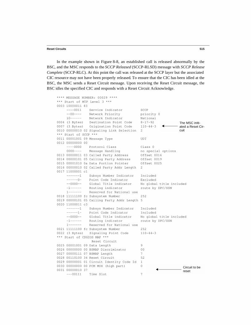
In the example shown in Figure 8-8, an established call is released abnormally by theBSC, and the MSC responds to the SCCP Released (SCCP-RLSD) message with SCCP ReleaseComplete (SCCP-RLC). At this point the call was released at the SCCP layer but the associatedCIC resource may not have been properly released. To ensure that the CIC has been idled at theBSC, the MSC sends a Reset Circuit message. Upon receiving the Reset Circuit message, theBSC idles the specified CIC and responds with a Reset Circuit Acknowledge.
**** MESSAGE NUMBER: 00029 ******* Start of MTP Level 3 ***0003 10000011 83 ----0011 Service Indicator SCCP --00---- Network Priority priority 0 10------ Network Indicator National 0004 (3 Bytes) Destination Point Code 8-17-92 0007 (3 Bytes) Origination Point Code 110-44-30010 00000010 02 Signaling Link Selection 2*** Start of SCCP ***0011 00001001 09 Message Type UDT0012 00000000 00 ----0000 Protocol Class Class 0 0000---- Message Handling no special options0013 00000011 03 Called Party Address Offset 00160014 00000101 05 Calling Party Address Offset 00190015 00001010 0a Data Portion Pointer Offset 00250016 00000010 02 Called Party Addr Length 20017 11000001 c1 -------1 Subsys Number Indicator Included ------0- Point Code Indicator Excluded --0000-- Global Title indicator No global title included -1------ Routing indicator route by DPC/SSN 1------- Reserved for National use 0018 11111100 fc Subsystem Number 2520019 00000101 05 Calling Party Addr Length 50020 11000011 c3 -------1 Subsys Number Indicator Included ------1- Point Code Indicator Included --0000-- Global Title indicator No global title included -1------ Routing indicator route by DPC/SSN 1------- Reserved for National use 0021 11111100 fc Subsystem Number 2520022 (3 Bytes) Signaling Point Code 110-44-3*** Start of CDGIOS MAP *** Reset Circuit0025 00001001 09 Data Length 90026 00000000 00 BSMAP Discriminator 000027 00000111 07 BSMAP Length 70028 00110100 34 Reset Circuit 520029 00000001 01 Circuit Identity Code Id 10030 00000000 00 PCM MUX (high part) 00031 00000010 37 ---00111 Time Slot 7
The MSC initi-ated a Reset Cir-cuit
Circuit to be reset

516 Chapter 8 • Terrestrial Circuit Management
(Continued) 011----- PCM MUX (low part) 30032 00000100 04 Cause Id 40033 00000001 01 Cause Length 10034 00000111 07 Cause Value OA&M intervention
Figure 8-9 Reset Circuit message example
Figure 8-9 shows the message structure and content of a Reset Circuit message. In thisexample message, only one circuit is specified and is contained in the mandatory Circuit IdentityCode IE. The Reset Circuit cause reason is set to OA&M intervention.
**** MESSAGE NUMBER: 00030 ******* Start of CDGIOS MAP *** Reset Circuit Acknowledge0028 00000110 06 Data Length 60029 00000000 00 BSMAP Discriminator 000030 00000100 04 BSMAP Length 40031 00110101 35 Reset Circuit Acknowledge 530032 00000001 01 Circuit Identity Code Id 10033 00000000 00 PCM MUX (high part) 00034 00000010 37 ---00111 Time Slot 7 011----- PCM MUX (low part) 3
Figure 8-10 Reset Circuit Acknowledge message example
Figure 8-10 illustrates the message structure and content of the Reset Circuit Acknowl-edge message sent from the BSC to the MSC. The BSC informs the MSC that the specified cir-cuit (PCM Mux 3 and timeslot 7) has been successfully idled.
8.4 Global System Reset
Either the BSC or MSC initiates the Global Reset procedure when a global failure occursor as a result of initialization. The Global Reset procedure is always invoked when the first sig-naling link connecting a BSC and MSC is brought into service. Upon receiving a Global Resetmessage, the receiving node releases the affected calls and idles all associated circuits. In thecase of the BSC, Block messages may also be sent for any unavailable CICs.
8.4.1 Global Reset at BSC Call Flow
Figure 8-11 shows the Global Reset procedure call flow when initiated by the BSC. TheBSC starts the procedure by sending the Reset message to the MSC and starts timer T4. Uponreceipt of the Reset message, the MSC starts timer T2, releases any affected calls, and marks allassociated CICs as idle and unblocked. The MSC waits for guard timer T2 to expire beforesending a Reset Acknowledge message to the BSC. In the meantime, the BSC may send Blocks
Circuit which was reset

Global System Reset 517
to the MSC for CICs that it determines should be blocked. The call flow shown in Figure8-11 isfollowed by descriptions of each individual step.
1. Reset (A-Interface):
Upon initialization or due to a global failure, the BSC initiates the Global Reset procedureby releasing affected calls, idling its CICs, and sending a Reset message to the MSC. TheBSC then starts timer T4 to wait for a Reset Acknowledge message from the MSC.
If the MSC receives a Reset message that indicates that the CDGIOS software versionbeing used by the BSC is less than that being used at the MSC, the MSC may choose toignore the Global Reset and take appropriate OA&M actions.
2. Blocks (A-Interface):
While waiting for a Reset Acknowledge message, the BSC may send Block messages forany CICs that it determines should not be requested by the MSC.
3. Block Acks (A-Interface):
Upon receiving a Block message from the BSC, the MSC locally blocks the specifiedCICs and sends one or more Block Acknowledge messages to the BSC.
4. Reset Ack (A-Interface):
The MSC idles all associated CICs and releases affected calls upon receipt of the GlobalReset indication from the BSC. After a guard timer delay of T2 seconds, the MSC sends aReset Acknowledge message to the BSC, indicating that it has performed the necessaryreset actions.
Figure 8-11 Global Reset at BSC call flow
BSC
1. Reset
4. Reset Ack
2. Blocks
3. BlockAcks
MSCMSC releases all calls/references and idles all CICs
T2delay
(guard time)
MSC informs the BSC that ithas performed the requiredreset actions by sending aReset Acknowledge messageafter a delay of T2.
T4BSC resends Global Reset if T4times out before a ResetAcknowledge message is received.
BSC sends Blocks messagesfor any unavailable CICs
...
...

518 Chapter 8 • Terrestrial Circuit Management
The BSC stops timer T4 upon receiving the Reset Acknowledge message from the MSC.If T4 expires before a Reset Acknowledge message is received, the BSC repeats the Glo-bal Reset procedure.
8.4.2 Global Reset at MSC Call Flow
As mentioned earlier, the MSC may also initiate a Global Reset. The message flow, illus-trated in Figure 8-12, is similar to the BSC-initiated Global Reset scenario described in Section8.4.1, “Global Reset at BSC Call Flow,” on page 516. In the case of a MSC-initiated GlobalReset, the MSC starts timer T16 upon sending the Reset message, and the BSC acknowledgesthe MSC with the Reset Acknowledge message after timer T13 expires.
8.4.3 Reset Glare Noted at BSC Call Flow
A Global Reset Glare may occur when both the BSC and MSC initiate the Global Resetprocedure around the same time. A glare condition at the BSC occurs when the BSC-sent Resetmessage is lost or cannot be processed by the MSC. The call flow for Global Reset Glare at theBSC is shown in Figur e8-13. In the call flow shown, the BSC starts the Global Reset procedureand sends a Reset message to the MSC. Around the same time, the MSC also invokes the GlobalReset procedure, sending a Reset message to the BSC. Upon receiving the Reset message fromthe MSC, the BSC determines that a Global Reset glare condition has occurred, assumes that itspreviously sent Reset message was lost, then processes the received Reset message. The BSC nolonger proceeds with its own initiated Global Reset.
Figure 8-12 Global Reset at MSC call flow
BSC
1. Reset
4. Reset Ack
BSC releases calls, associatedreferences, and idle all CICs
T13delay(guard time)
The BSC sends out ResetAcknowledge after a delayof T13.
T16 MSC resends another Resetif T16 times out before aReset Acknowledge isreceived.
2. Blocks
3. BlockAcks
BSC sends Blocksfor unavailable CICs
MSC
...
...

Global System Reset 519
1. Reset (A-Interface):
A Reset is first sent by the BSC, and the BSC starts timer T4. The glare condition at theBSC occurs when this message is lost or cannot be processed by the MSC, and the MSCsends its own Reset message to the BSC.
2. Reset (A-Interface):
The MSC starts the Global Reset procedure and sends out a Reset message to the BSC andstarts timer T16.
Upon receiving the Reset message, the BSC determines that a glare condition has occurredand continues to process the received Reset message. The BSC no longer proceeds with itsown initiated Global Reset procedure and assumes that the Reset message it sent was lost.The BSC stops Timer T4 and starts delay timer T13.
3. Blocks (A-Interface):
If required, Blocks messages are sent from the BSC for CICs not available at the BSC.
4. Block Acks (A-Interface):
The MSC locally blocks the specified CICs and sends one or more Block Acknowledgemessages to the BSC.
Figure 8-13 Global Reset Glare noted at BSC call flow
BSC
1. Reset
5. Reset Ack
3. Blocks
4. BlockAcks
MSCAt nearly the same time as theBSC, the MSC sends a GlobalReset.
T13delay(guard time)
T4
BSC sends Blocksfor unavailable CICs
...
...
2. Reset
T16BSC sends a Global ResetAcknowledge after a delay ofT13.
MSC resends Global Reset if T16times out before a ResetAcknowledge is received.
BSC determines that a glarecondition occurred andcontinues to process the MSC’sGlobal Reset.

520 Chapter 8 • Terrestrial Circuit Management
5. Reset Ack (A-Interface):
Upon expiry of timer T13, the BSC sends a Reset Acknowledge. The MSC stops timerT16 after receiving this message.
8.4.4 Reset Glare Noted at MSC Call Flow
Parallel Global Reset procedures at both the MSC and BSC may also result in a reset glarecondition at the MSC. The message flow for such a condition is similar to the BSC glare sce-nario described in Section 8.4.3, “Reset Glare Noted at BSC Call Flow,” on page518. The maindifference is that the MSC is the first node to send the Reset message. Upon receiving the Resetmessage from the BSC, the MSC determines that glare has occurred and proceeds to process thereceived Reset message. The MSC stops its own initiated Global Reset procedure. Figure 8-14illustrates the message flow for Global Reset glare noted at the MSC.
8.4.5 Reset Glare Noted at Both BSC and MSC
When both the MSC and BSC initiate Global Reset procedures at nearly the same time, itis possible for Reset Glare conditions to occur simultaneously at both nodes. Each node deter-mines that Reset glare has occurred when a Reset message is received soon after the initial Resetmessage has been sent. When this occurs, both the MSC and BSC each assume that the Resetmessages they previously sent were lost, act as though they are not performing a reset procedure,and process the received Reset message. The call flow for Reset glare noted at both the MSC andBSC is shown in Figure 8-15.
Figure 8-14 Global Reset Glare noted at MSC call flow
BSC
2. Reset
5. Reset Ack
3. Blocks
4. BlockAcks
MSC
T2delay
(guard time)
MSC clears all resources,sends out Reset Acknowledgeafter a delay of T2.
T4BSC resends Reset message ifT4 times out before a ResetAcknowledge is received.
BSC sends Blocksfor unavailable CICs
...
...
1. ResetBSC sends a Reset beforereceiving a Reset from theMSC.
MSC determines that glarehas occurred and continues toprocess Reset received fromthe BSC.T16

Global System Reset 521
1. Reset (A-Interface):
Both the MSC and BSC send Reset messages at nearly the same time. The BSC startstimer T4 and the MSC starts timer T16.
Upon receiving the Reset message from the MSC, the BSC notes that Reset glare hasoccurred, assumes that its previously sent Reset message has been lost, and continues toprocess the received Reset message. The BSC stops timer T4 and starts delay timer T13.
Similarly, when the MSC receives the Reset message from the BSC, it notes that a Resetglare has occurred, assumes that its previously sent Reset message has been lost, and con-tinues to process the received Reset message. The MSC stops timer T16 and starts delaytimer T2.
2. Blocks (A-Interface):
If required, Blocks messages are sent from the BSC for CICs not available at the BSC.
3. Block Acks (A-Interface):
The MSC locally blocks the specified CICs and sends one or more Block Acknowledgemessages to the BSC.
4. Global Reset Ack (A-Interface):
The MSC sends a Reset Acknowledge message after delay timer T2 expires.
Figure 8-15 Global Reset Glare noted at both BSC and MSC call flow
BSC
1. Reset
4. Reset Ack
2. Blocks
3. BlockAcks
MSC
T2delay
(guard time)
MSC clears all resources,then sends a Reset Ack aftera delay of T2.
BSC sends Blocksfor unavailable CICs
...
...
1. Reset
T16T4
T13delay(guard time)
5. Reset Ack
BSC clears all resources, thensends a Reset Ack after a delayof T13.
BSC determines glare hasoccurred and assumes theReset previously sent was lost.BSC continues to process thereceived Reset.
MSC determines that glarehas occurred and assumes thatthe Reset previously sent waslost. MSC continues toprocess the received Reset.

522 Chapter 8 • Terrestrial Circuit Management
5. Global Reset Ack (A-Interface):
The BSC sends a Reset Acknowledge message after delay timer T13 expires.
8.4.6 Global Reset Messages
The following sections contain descriptions of the A-Interface messages used by both theMSC and BSC during a Global Reset.
8.4.6.1 Reset The Reset message (Table 8-7) is a BSMAP message sent by either the BSC or MSC to
initiate a Global Reset at the remote end. It is sent as a connectionless SCCP-UDT messagetype.
CDGIOS specifies that the mandatory Cause IE contained in the Reset message be set to"operations and maintenance" or "equipment failure.” For an operator-induced Global Reset, theReset message is sent with a Cause IE of “operations and maintenance.”
The required Software Version IE is sent to the remote end to convey information regard-ing the CDGIOS software version being used. The CDGIOS version is specified using the a.b.cformat, where a is the major revision, b is the minor revision, and c is the point release. TheSoftware Version IE also contains a load identity for each manufacturer software load and maybe used by the wireless carrier to exchange information between network entities.
• BSAP Message Type: BSMAP• SCCP Message Type: SCCP-Unit Data (UDT)• Direction: BSC ↔ MSC
Table 8-7 Reset Message (CDGIOS 6.1.6.6)
BitMap Param IE #Oct Range Type IOS Ref
0000 0000 (00H)LLLL LLLL
BSMAP header 2 Msg Discrim. = 0 (BSMAP)
L = BSMAP msg length
M 6.2.2.1
6.2.2.3
0011 0000 (30H) Msg Type 1 Global Reset Msg M 6.2.2.4

Global System Reset 523
8.4.6.2 Reset Acknowledge
The Reset Acknowledge message is a BSMAP message sent by either the BSC or MSC toacknowledge a Global Reset (Table 8-8). It is sent after the local node has cleared all affectedcalls and associated SCCP connections. The Reset Acknowledge message is sent as a connec-tionless SCCP-UDT message type.
The required Software Version IE is sent by the BSC or MSC to the remote entity to con-vey CDGIOS software release information. For further details on the Software Version IE pleasesee the description provided for the Reset message in Section 8.4.6.1, “Reset,” on page 522.
• BSAP Message Type: BSMAP
• SCCP Message Type: SCCP-Unit Data (UDT)
• Direction: BSC ↔ MSC
0000 0100 (04H)LLLL LLLL0ccc cccc
Cause 3 L = 01H, c = cause
07H—OA&M intervention
20H—equipment failure
M 6.2.2.19
0011 0001 (31H)LLLL LLLLaaaa aaaabbbb bbbbcccc ccccmmmm mmmm……
Software Ver-sion
Var-iable
L = length
a = Major Revision
b = Minor Revision
c = Point Release
m = manufacturer information
O,R 6.2.2.65
Table 8-8 Reset Acknowledge Message (CDGIOS 6.1.6.7)
BitMap Param IE #Oct Range Type IOS Ref
0000 0000 (00H)LLLL LLLL
BSMAP header
2 Msg Discrim. = 0 (BSMAP)
L = BSMAP msg length
M 6.2.2.1
6.2.2.3
0011 0001 (31H) Msg Type 1 Global Reset Ack Msg M 6.2.2.4
0011 0001 (31H)……
Software Ver-sion
Var-iable
Same as element in Tabl e8-7, Reset Message
O,R 6.2.2.65
Table 8-7 Reset Message (CDGIOS 6.1.6.6) (Continued)
BitMap Param IE #Oct Range Type IOS Ref

524 Chapter 8 • Terrestrial Circuit Management
8.4.7 Global Reset with Blocks Example Call Flow
Figure 8-16 contains a summary message call flow that is similar to what would be seenon test equipment monitoring the A-Interface when the first signaling link connecting a BSC andMSC is brought into service. The intent of this example is to illustrate the call flow associatedwith the Global Reset procedure, including the sending of Block messages by the BSC duringsystem initialization. Subsequent figures illustrate the complete message’s content, includingMTP and SCCP layers. In this example, the BSC’s point code is 1-1-1, and the MSC’s pointcode is 1-2-4.
+----------------+-----------------+--------------------------+--- From Time OPC DPC +----------------+-----------------+--------------------------+--- C 21:06:20,586,011 MTP-L2 LSSU-SIOS
D 21:06:20,589,772 MTP-L2 LSSU-SIOS D 21:06:21,325,385 MTP-L2 LSSU-SIO C 21:06:22,279,067 MTP-L2 LSSU-SIO D 21:06:22,283,210 MTP-L2 LSSU-SIEC 21:06:23,435,130 MTP-L2 LSSU-SIE
C 21:06:23,980,240 1-2-4 1-1-1 T+M SLTM D 21:06:23,987,138 1-1-1 1-2-4 T+M SLTM D 21:06:23,991,793 1-1-1 1-2-4 T+M SLTA C 21:06:23,991,741 1-2-4 1-1-1 T+M SLTA D 21:06:24,005,011 1-1-1 1-2-4 MTP3 TRA D 21:06:24,006,887 1-1-1 1-2-4 MTP3 TRA
D 21:06:28,033,172 1-1-1 1-2-4 SCCP UDT SCMG SST C 21:06:29,299,796 1-2-4 1-1-1 MTP3 TRA D 21:06:33,032,978 1-1-1 1-2-4 SCCP UDT SCMG SST C 21:06:33,040,961 1-2-4 1-1-1 SCCP UDT SCMG SSA C 21:06:59,386,758 1-2-4 1-1-1 SCCP UDT SCMG SST D 21:06:59,401,279 1-1-1 1-2-4 SCCP UDT SCMG SSA C 21:07:21,499,754 1-2-4 1-1-1 SCCP UDT BSMAP RSTD 21:07:21,649,647 1-1-1 1-2-4 SCCP UDT BSMAP BLO C 21:07:21,666,881 1-2-4 1-1-1 SCCP UDT BSMAP BLA D 21:07:21,702,149 1-1-1 1-2-4 SCCP UDT BSMAP BLO D 21:07:21,707,276 1-1-1 1-2-4 SCCP UDT BSMAP BLO D 21:07:21,712,397 1-1-1 1-2-4 SCCP UDT BSMAP BLO D 21:07:21,717,520 1-1-1 1-2-4 SCCP UDT BSMAP BLO D 21:07:21,722,784 1-1-1 1-2-4 SCCP UDT BSMAP BLO D 21:07:21,727,900 1-1-1 1-2-4 SCCP UDT BSMAP BLO D 21:07:21,733,024 1-1-1 1-2-4 SCCP UDT BSMAP BLO D 21:07:21,738,270 1-1-1 1-2-4 SCCP UDT BSMAP BLO D 21:07:21,743,400 1-1-1 1-2-4 SCCP UDT BSMAP BLO D 21:07:21,748,523 1-1-1 1-2-4 SCCP UDT BSMAP BLO D 21:07:21,753,645 1-1-1 1-2-4 SCCP UDT BSMAP BLO D 21:07:21,758,901 1-1-1 1-2-4 SCCP UDT BSMAP BLO D 21:07:21,764,024 1-1-1 1-2-4 SCCP UDT BSMAP BLO D 21:07:21,769,148 1-1-1 1-2-4 SCCP UDT BSMAP BLO D 21:07:21,774,407 1-1-1 1-2-4 SCCP UDT BSMAP BLO D 21:07:21,779,523 1-1-1 1-2-4 SCCP UDT BSMAP BLO
MTP2 layer initial link alignment in progress
MTP3 layer traffic started
SCCP layer brought into service
MSC sends Reset message
BSC sends Blocks for unavailable CICs

Global System Reset 525
(Continued) C 21:07:21,906,386 1-2-4 1-1-1 SCCP UDT BSMAP BLA C 21:07:21,916,506 1-2-4 1-1-1 SCCP UDT BSMAP BLA C 21:07:21,926,762 1-2-4 1-1-1 SCCP UDT BSMAP BLA C 21:07:21,936,381 1-2-4 1-1-1 SCCP UDT BSMAP BLA C 21:07:21,946,758 1-2-4 1-1-1 SCCP UDT BSMAP BLA C 21:07:21,956,139 1-2-4 1-1-1 SCCP UDT BSMAP BLA C 21:07:21,965,758 1-2-4 1-1-1 SCCP UDT BSMAP BLA C 21:07:21,970,756 1-2-4 1-1-1 SCCP UDT BSMAP BLA C 21:07:21,975,635 1-2-4 1-1-1 SCCP UDT BSMAP BLA C 21:07:21,980,506 1-2-4 1-1-1 SCCP UDT BSMAP BLA C 21:07:21,985,505 1-2-4 1-1-1 SCCP UDT BSMAP BLA C 21:07:21,990,394 1-2-4 1-1-1 SCCP UDT BSMAP BLA C 21:07:21,995,382 1-2-4 1-1-1 SCCP UDT BSMAP BLA C 21:07:22,000,258 1-2-4 1-1-1 SCCP UDT BSMAP BLA C 21:07:22,005,131 1-2-4 1-1-1 SCCP UDT BSMAP BLA C 21:07:22,010,012 1-2-4 1-1-1 SCCP UDT BSMAP BLA D 21:07:23,923,049 1-1-1 1-2-4 T+M SLTM C 21:07:23,926,531 1-2-4 1-1-1 T+M SLTA C 21:07:24,305,785 1-2-4 1-1-1 T+M SLTM D 21:07:24,314,677 1-1-1 1-2-4 T+M SLTA D 21:08:16,534,568 1-1-1 1-2-4 SCCP UDT BSMAP RSTA D 21:08:23,923,471 1-1-1 1-2-4 T+M SLTM C 21:08:23,927,327 1-2-4 1-1-1 T+M SLTA C 21:08:25,312,844 1-2-4 1-1-1 T+M SLTM D 21:08:25,323,863 1-1-1 1-2-4 T+M SLTA
Figure 8-16 Global Reset with Blocks after Initial Link Alignment example call flow
The initial messages in Figure 8-16 are associated with the alignment of the only Signal-ing System 7 (SS7) signaling link connecting the MSC and BSC. MTP 2 alignment first takesplace, followed by a traffic restart at MTP 3, then the exchange of signaling link test and mainte-nance messages. Next, the SCCP layers are brought into service at both nodes through theexchange of Subsystem Test (SST) and Subsystem Allowed (SSA) messages. Finally, the BSAP(application) layer terrestrial circuit resource function initiates a Global Reset to bring the asso-ciated CICs into service. In this example, the MSC initiates the Global Reset, and the BSCresponds with multiple Block messages to inform the MSC of unavailable CICs. After complet-ing its initialization and waiting for timer T13 to expire, the BSC responds to the previouslyreceived Reset message with a Reset Acknowledge message. At this point, both the link and ter-restrial circuits are now available and in service.
1:C: 21:07:21,499,754 1-2-4 1-1-1 SCCP UDT BSMAP RST ----0011 Service Indicator SCCP --00---- Sub-Service: Priority priority 0 10------ Sub-Service: Network Ind National ***B3*** Destination Point Code 1-1-1 ***B3*** Originating Point Code 1-2-4 00000011 Signaling Link Selection 3 00001001 SCCP Message Type UDT
MSC acknowl-edges Blocks
BSC acknowl-edges Reset

526 Chapter 8 • Terrestrial Circuit Management
(Continued) ----0000 Protocol Class Class 0 0000---- Message Handling Discard message on error 00000011 Pointer to parameter 3 00001000 Pointer to parameter 8 00001101 Pointer to parameter 13 Called address parameter 00000101 Parameter Length 5 -------1 Subsystem No. Indicator SSN present ------1- Point Code Indicator PC present --0000-- Global Title Indicator No global title included -1------ Routing Indicator Route on DPC + SSN 1------- For national use National address 11111100 Subsystem number 252 ***B3*** Called Party SPC 1-1-1 Calling address parameter 00000101 Parameter Length 5 -------1 Subsystem No. Indicator SSN present ------1- Point Code Indicator PC present --0000-- Global Title Indicator No global title included -1------ Routing Indicator Route on DPC + SSN 1------- For national use National address 11111100 Subsystem number 252 ***B3*** Called Party SPC 1-2-4 Data parameter 00001011 Parameter length 11 CDGIOS (BSSMAP) (BSMAP) RESET -------0 Discrimination bit D BSSMAP 0000000- Filler 0 00001001 Message Length 9 00110000 Message Type 48 00000100 IE Name Cause 00000001 IE Length 1 -0100000 Cause Value Equipment failure 0------- Extension bit No extension 00110001 IE Name Software Version 00000011 IE Length 3 00000011 IOS version 3.1.1 00000001 00000001
Figure 8-17 Global Reset message example
Figure 8-17 illustrates the message structure and content of a Reset message. The manda-tory cause value is set to equipment failure because, in this example, the system was restarted,due to a system failure.
CDGIOS MSC - BSC (BSSMAP) (BSMAP) BLO (= Block) -------0 Discrimination bit D BSSMAP 0000000- Filler 0 00000111 Message Length 7

Global System Reset 527
(Continued) 01000000 Message Type 64 00000001 IE Name Circuit Identity Code 00000000 PCM Multiplex a-h 0 ---00001 Timeslot in use 1 001----- PCM Multiplex i-k 1 00000100 IE Name Cause 00000001 IE Length 1 -0000111 Cause Value OA&M intervention 0------- Extension bit No extension
Figure 8-18 Block message example
Figure 8-18 illustrates the message structure and content of a Block message. Because theSCCP and MTP layers are similar to those found in the Reset message example shown inFigure 8-17, they are not repeated here. In this example, the BSC sends individual Block mes-sages for each CIC that it determines should be blocked. The Block message shown in Figure 8-18 requests that the MSC block the CIC associated with PCM mux 1 and timeslot 1. The reasonspecified for requesting the block is OA&M intervention.
CDGIOS MSC - BSC (BSSMAP) (BSMAP) BLA (= Block Acknowledge) -------0 Discrimination bit D BSSMAP 0000000- Filler 0 00000100 Message Length 4 01000001 Message Type 65 00000001 IE Name Circuit Identity Code 00000000 PCM Multiplex a-h 0 ---00001 Timeslot in use 1 001----- PCM Multiplex i-k 1
Figure 8-19 Block Acknowledge message example
Figure 8-19 illustrates the message structure and content of a Block Acknowledge mes-sage. In this example message, the MSC acknowledges the blocking of a single CIC associatedwith PCM mux 1 and timeslot 1.
CDGIOS MSC - BSC (BSSMAP) (BSMAP) RSTA (= Reset Acknowledge) -------0 Discrimination bit D BSSMAP 0000000- Filler 0 00000110 Message Length 6 00110001 Message Type 49 00110001 IE Name Software Version 00000011 IE Length 3 00000011 IOS version 3.1.1 00000001 00000001
Figure 8-20 Global Reset Acknowledge message example

528 Chapter 8 • Terrestrial Circuit Management
Figure 8-20 illustrates the message structure and content of a Reset Acknowledge messagesent by the BSC in response to the MSC-initiated Global Reset earlier. The software version IEspecifies that CDGIOS 3.1.1 is being used.
8.5 A7-Interface Global Reset
In a CDMA network, direct connections between BSCs may exist to facilitate soft hand-offs between BSCs. Like the MSC–BSC interface, these BSC–BSC interfaces also require Ter-restrial Facility Management procedures to maintain the integrity of the connections. Recall thatthe signaling portion of the BSC–BSC connection is referred to as the A7-Interface and that datais sent over the A3 traffic connection (See Section 1.3, “Open A-Interface Network Architec-ture,” on page6 and Section 7.4, “IS-95 to IS-95 Direct BSC-BSC Soft Handoff,” on page473).When a BSC experiences a failure that results in losing the A3/A7 connections, an A7 GlobalReset procedure is performed to release all associated references and to reinitialize the connec-tions.
8.5.1 A7 Global Reset at BSC Call Flow
During initialization or due to a failure that results in the BSC losing A7 transaction refer-ence information, the BSC sends a A7-Reset message to one or more remote BSCs. The callflow for resetting the A7 connections is similar to that of a BSC-initiated Global Reset on theA1-Interface, described in Section 8.4.1, “Global Reset at BSC Call Flow,” on page516.
After releasing all affected resources, the BSC sends A7-Reset messages to other knownBSCs and starts timer T4. Upon receipt of the A7-Reset message, the remote BSCs release allaffected virtual calls and references, then wait for T2 seconds before sending an A7-ResetAcknowledge message to the initiating BSC. If timer T4 expires before an A7-Reset Acknowl-edge message is received, the initiating BSC repeats the reset procedure with the other BSC.Figure 8-21 shows the call flow when the A7 Reset procedure is initiated by a BSC.
Figure 8-21 A7 Global Reset call flow
BSC
1. A7-Reset
2. A7-Reset Ack
other BSCs
T2delay
BSCs cleared all connectionresources and sends an A7-Reset Acknowledge messageafter a delay of T2.
T4BSC resends A7-Reset if T4expires before an A7-ResetAcknowledge is received.

A7-Interface Global Reset 529
8.5.2 A7 Global Reset Glare Noted at Initiating BSC
As with the A1-Interface, Reset Glares may also occur over the A7-Interface. If the initiat-ing BSC receives a A7-Reset message after sending its own A7-Reset, it determines that A7-Reset glare has occurred and assumes that its previously sent A7-Reset message was lost. Theinitiating (original) BSC processes the received A7-Reset and sends a A7-Reset Acknowledgemessage after timer T2 expires. The call flow is illustrated in Figur e8-22.
8.5.3 A7 Global Reset Glare Noted at Two BSCs
It is possible that both the local and remote BSC encounter A7-Reset glare. Each nodedetermines that Reset Glare has occurred when an A7-Reset message is received after the initialA7-Reset message has been sent. When this occurs, both the BSCs assume that the A7-Resetmessages they previously sent were lost, stop timer T4, act as though they are not performing areset procedure, and process the received A7-Reset message. Upon expiry of timer T2, eachnode sends a A7-Reset Acknowledge message to the remote end (Figure 8-23).
Figure 8-22 A7 Global Reset Glare noted at initiating BSC
Figure 8-23 A7 Global Reset noted at two BSCs
BSC
1. A7-Reset
3. A7-Reset Ack
other BSCs
T2delay
The remote BSCs does notreceive the A7-Reset or timingconditions exist such that itsends its own A7-Reset.
T4Upon processing the receivedA7-Reset and after timer T2expires, the BSC sends an A7-Reset Acknowledge.
2. A7-Reset
T4
BSC 1
1. A7-Reset
3. A7-Reset Ack
BSC 2BSC 1 sends an A7-Resetand also receives A7-Resetfrom BSC 2
T2delay
T4BSC 1 sends A7-ResetAcknowledge after a delayof T2.
1. A7-Reset
T4
T2delay
4. A7-Reset Ack
BSC 2 sends an A7-Reset andalso receives A7-Reset fromBSC 1
BSC 2 sends A7-ResetAcknowledge after a delay of T2.

530 Chapter 8 • Terrestrial Circuit Management
8.5.4 A7 Global Reset Messages
The following sections describe the A7-Interface messages that are used in the A7 GlobalReset procedure.
8.5.4.1 A7-Reset
The A7-Reset message is sent from one BSC to another BSC to initiate an A7 GlobalReset (Table 8-9). All virtual connections, references, and associated transaction resources arereleased and reinitialized.
The required Cause IE and Software Version IE are identical to those described for theReset message in Section 8.4.6.1, “Reset,” on page522 .
• Direction: BSC ↔ BSC
8.5.4.2 A7-Reset Ack
The A7-Reset Acknowledge message is sent from one BSC to another BSC to acknowl-edge the completion of an A7 Global Reset (Table 8-10).
The required Software Version IE is identical to that described for the Reset message inSection 8.4.6.1, “Reset,” on page 522.
• Direction: BSC <-> BSC
Table 8-9 A7-Reset (CDGIOS 6.1.12.11)
BitMap Param IE #Oct Range Type IOS Ref
1000 1010 (8AH) Msg Type II 1 A7-Reset Msg M 6.2.2.5
0000 0100 (04H)LLLL LLLL0ccc cccc
Cause 3 L = 01H
c = cause
07H—OA&M intervention
20H—equipment failure
O,R 6.2.2.19
0011 0001 (31H)…….
Software Ver-sion
Var-iable
Same element in Tabl e8-7, Reset Message
O,R 6.2.2.65

A7-Interface Global Reset 531
References
1. CDG-IOS version 3.1.1, CDMA Development Group MSC to BS Interface Inter-Operability Specification. June 1999.
2. CDG-IOS version 2.0, CDMA Development Group MSC to BS Interface Inter-Operability Specification. Septem-ber 1998.
3. Telecommunications Industry Association, TIA/EIA/IS-634-A, MSC-BS Interface (A-Interface) for Public 800 MHz. July 1998.
4. Telecommunications Industry Association , TIA/EIA/TSB-80, MSC-BS Interface (A-Interface) for Public 800
MHz. October 1996.5. American National Standards Institute, ANSI T1.111, Signaling System No. 7 (SS7)—Message Transfer Part
(MTP). June 1992.6. American National Standards Institute, ANSI T1.112, Signaling System No. 7 (SS7)—Signaling Connection Con-
trol Part (SCCP). October 1992.
Table 8-10 A7-Reset Ack (CDGIOS 6.1.12.12)
BitMap Param IE #Oct Range Type IOS Ref
1000 1011 (8BH) Msg Type II 1 A7-Reset Ack Msg M 6.2.2.5
0011 0001 (31H)…….
Software Ver-sion
Var-iable
Same element in Table 8-7, Reset Message
O,R 6.2.2.65

532 Chapter 8 • Terrestrial Circuit Management