terahertz wireless communications based on … · terahertz wireless communications based on...
TRANSCRIPT
Terahertz wireless communications based on photonics technologies
Tadao Nagatsuma,1,* Shogo Horiguchi,1 Yusuke Minamikata,1 Yasuyuki Yoshimizu,1 Shintaro Hisatake,1 Shigeru Kuwano,2 Naoto Yoshimoto,2 Jun Terada,2
and Hiroyuki Takahashi1 1Graduate School of Engineering Science, Osaka University, 1-3 Machikaneyama, Toyonaka, 560-8531, Japan
2NTT Access Network Service Systems Laboratories, NTT Corporation, 1-1 Hikarinooka, Yokosuka, Kanagawa, 239-0847, Japan
Abstract: There has been an increasing interest in the application of terahertz (THz) waves to broadband wireless communications. In particular, use of frequencies above 275 GHz is one of the strong concerns among radio scientists and engineers, because these frequency bands have not yet been allocated at specific active services, and there is a possibility to employ extremely large bandwidths for ultra-broadband wireless communications. Introduction of photonics technologies for signal generation, modulation and detection is effective not only to enhance the bandwidth and/or the data rate, but also to combine fiber-optic (wired) and wireless networks. This paper reviews recent progress in THz wireless communications using telecom-based photonics technologies towards 100 Gbit/s.
©2013 Optical Society of America
OCIS codes: (060.5625) Radio frequency photonics; (060.0060) Fiber optics and optical communications.
References and links
1. T. Nagatsuma, H.-J. Song, and Y. Kado, “Challenges for ultrahigh speed wireless communications using terahertz waves,” J. Terahertz Sci. Technol. 3, 55–65 (2010).
2. J. Federici and L. Moeller, “Review of terahertz and subterahertz wireless communications,” J. Appl. Phys. 107(11), 111101 (2010).
3. T. Kleine-Ostmann and T. Nagatsuma, “A review on terahertz communications research,” J. Infrared Milli. Terahz. Waves 32(2), 143–171 (2011).
4. H.-J. Song and T. Nagatsuma, “Present and future of terahertz communications,” IEEE Trans. Terahertz Sci. Technol. 1(1), 256–263 (2011).
5. A. Hirata, H. Takahashi, R. Yamaguchi, T. Kosugi, K. Murata, T. Nagatsuma, N. Kukutsu, and Y. Kado, “Transmission characteristics of 120-GHz-band wireless link using radio-on-fiber technologies,” J. Lightwave Technol. 26(15), 2338–2344 (2008).
6. A. Hirata, R. Yamaguchi, T. Kosugi, H. Takahashi, K. Murata, T. Nagatsuma, N. Kukutsu, Y. Kado, N. Iai, S. Okabe, S. Kimura, H. Ikegawa, H. Nishikawa, T. Nakayama, and T. Inada, “10-Gbit/s wireless link using InP HEMT MMICs for generating 120-GHz-band millimeter-wave signal,” IEEE Trans. Microw. Theory Tech. 57(5), 1102–1109 (2009).
7. J. Takeuchi, A. Hirata, H. Takahashi, and N. Kukutsu, “10-Gbit/s bi-directional and 20-Gbit/s uni-directional data transmission over a 120-GHz-band wireless link using a finline ortho-mode transducer,” in Proc. Asia-
Pacic Microwave Conf.(APMC 2010), pp. 195–198.
8. R. Fujimoto, R. M. Motoyoshi, K. Takano, and M. Fujishima, “A 120 GHz / 140 GHz dual-channel ASK receiver using standard 65 nm CMOS technology,” in Proc. 41st European Microwave Conf. (EuMC 2011), pp. 1189–1192.
9. C. Wang, C. Lin, Q. Chen, X. Deng, and J. Zhang, “0.14 THz high speed data communication over 1.5 kilometers,” in Tech. Dig. of Infrared Millimeter, and Terahertz Waves (IRMMW-THz 2012), paper Tue-A-2–4.
10. G. Ducournau, P. Szriftgiser, D. Bacquet, A. Beck, T. Akalin, E. Peytavit, M. Zaknoune, and J. F. Lampin, “Optically power supplied Gbit/s wireless hotspot using 1.55 μm THz photomixer and heterodyne detection at 200 GHz,” Electron. Lett. 46(19), 1349–1351 (2010).
11. I. Kallfass, J. Antes, T. Schneider, F. Kurz, D. Lopez-Diaz, S. Diebold, H. Massler, A. Leuther, and A. Tessmann, “All active MMIC-based wireless communication at 220 GHz,” IEEE Trans. Terahertz Sci. Technol. 1(2), 477–487 (2011).
#193985 - $15.00 USD Received 16 Jul 2013; revised 19 Sep 2013; accepted 23 Sep 2013; published 30 Sep 2013(C) 2013 OSA 7 October 2013 | Vol. 21, No. 20 | DOI:10.1364/OE.21.023736 | OPTICS EXPRESS 23736

12. S. Koenig, D. Lopez-Diaz, J. Antes, R. Henneberger, R. Schmogrow, D. Hillerkuss, R. Palmer, T. Zwick, C. Koos, W. Freude, O. Ambacher, I. Kallfass, and J. Lewthold, “100 Gbit/s wireless link with mm-wave photonics,” in Tech. Dig. of Optical Fiber Communication Conference and Exposition and the National Fiber Optics Engineers Conference (OFC/NFOEC 2013), postdeadline paper.
13. H.-J. Song, K. Ajito, A. Hirata, A. Wakatsuki, Y. Muramoto, T. Furuta, N. Kukutsu, T. Nagatsuma, and Y. Kado, “8 Gbit/s wireless data transmission at 250 GHz,” Electron. Lett. 45(22), 1121–1122 (2009).
14. C. Jastrow, K. Münter, R. Piesiewicz, T. Kürner, M. Koch, and T. Kleine-Ostmann, “300 GHz transmission system,” Electron. Lett. 44(3), 213–214 (2008).
15. R. Piesiewicz, M. Jacob, M. Koch, J. Schoebel, and T. Kürner, “Performance analysis of future multi-gigabit wireless communication systems at THz frequencies with highly directive antennas in realistic indoor environments,” IEEE J. Sel. Top. Quantum Electron. 14(2), 421–430 (2008).
16. T. Nagatsuma, H.-J. Song, Y. Fujimoto, A. Hirata, K. Miyake, K. Ajito, A. Wakatuski, T. Furuta, and N. Kukutsu, “Giga-bit wireless link using 300-400 GHz bands,” in Tech. Dig. of IEEE International Topical Meeting on Microwave Photonics (MWP 2009), paper Th.2.3.
17. K. Arakawa, T. Takada, K. Miyake, H.-J. Song, K. Ajito, N. Kukutsu, and T. Nagatsuma, “Application of high-power photodiode-arrays to 300 GHz-band wireless link,” in Tech. Dig. Asia-Pacific Microwave Photonics Conference (APMP 2012), paper WD-3.
18. H.-J. Song, K. Ajito, Y. Muramoto, A. Wakatsuki, T. Nagatsuma, and N. Kukutsu, “24 Gbit/s data transmission in 300 GHz band for future terahertz communications,” Electron. Lett. 48(15), 953–954 (2012).
19. T. Nagatsuma, “Generating millimeter and terahertz waves by photonics for communications and sensing,” in Tech. Dig. of IEEE International Microwave Symposium (IMS 2013), paper WE2H–1.
20. L. Moeller, J. F. Federici, and K. Su, “THz wireless communications: 2.5 Gb/s error-free transmission at 625 GHz using a narrow-bandwidth 1 mW THz source,” in Tech. Dig. of URSI General Assembly and Scientific Symposium, Turkey (URSI GASS 2011), paper DAF2–7.
21. X. Pang, A. Caballero, A. Dogadaev, V. Arlunno, R. Borkowski, J. S. Pedersen, L. Deng, F. Karinou, F. Roubeau, D. Zibar, X. Yu, and I. T. Monroy, “100 Gbit/s hybrid optical fiber-wireless link in the W-band (75-110 GHz),” Opt. Express 19(25), 24944–24949 (2011).
22. A. Kanno, K. Inagaki, I. Morohashi, T. Sakamoto, T. Kuri, I. Hosako, T. Kawanishi, Y. Yoshida, and K. Kitayama, “40 Gb/s W-band (75-110 GHz) 16-QAM radio-over-fiber signal generation and its wireless transmission,” Opt. Express 19(26), B56–B63 (2011).
23. R. Sambaraju, D. Zibar, A. Caballero, I. T. Monroy, R. Alemany, and J. Herrera, “100 GHz wireless on-off-keying link employing all photonic RF carrier generation and digital coherent detection,” in Proc. of Access Networks and In-house Communications (ANIC 2010), paper AThA4.
24. A. Kanno, K. Inagaki, I. Morohashi, T. Sakamoto, T. Kuri, I. Hosako, T. Kawanishi, Y. Yoshida, and K. Kitayama, “20-Gb/s QPSK W-band (75-110GHz) wireless link in free space using radio-over-fiber technique,” IEICE Electron. Express 8(8), 612–617 (2011).
25. X. Pang, A. Caballero, A. Dogadaev, V. Arlunno, L. Deng, R. Borkowski, J. S. Pedersen, D. Zibar, X. Yu, and I. T. Monroy, “25 Gbit/s QPSK hybrid fiber-wireless transmission in the W-Band (75-110GHz) with remote antenna unit for in-building wireless networks,” IEEE Photonics Journal 4(3), 691–698 (2012).
26. A. Kanno, T. Kuri, I. Hosako, T. Kawanishi, Y. Yoshida, Y. Yasumura, and K. Kitayama, “Optical and millimeter-wave radio seamless MIMO transmission based on a radio over fiber technology,” Opt. Express 20(28), 29395–29403 (2012).
27. X. Li, Z. Dong, J. Yu, N. Chi, Y. Shao, and G. K. Chang, “Fiber-wireless transmission system of 108 Gb/sdata over 80 km fiber and 2×2multiple-input multiple-output wireless links at 100 GHz W-band frequency,” Opt. Lett. 37(24), 5106–5108 (2012).
28. K. Okada, L. Ning, K. Matsushita, K. Bunsen, R. Murakami, A. Musa, T. Sato, H. Asada, N. Takayama, S. Ito, W. Chaivipas, R. Minami, T. Yamaguchi, Y. Takeuchi, H. Yamagishi, M. Noda, and A. Matsuzawa, “A 60-GHz 16QAM/8PSK/QPSK/BPSK direct-conversion transceiver for IEEE802.15.3c,” IEEE J. Solid-State Circuits 46(12), 2988–3004 (2011).
29. S. Emami, R. F. Wiser, E. Ali, M. G. Forbes, M. Q. Gordon, S. Lo Guan Xiang, P. T. McElwee, J. Parker, J. R. Tani, J. M. Gilbert, and C. H. Doan, “A 60GHz CMOS phased-array transceiver pair for multi-Gb/s wireless communications,” in Tech. Dig. of IEEE Intern. Solid-State Circuits Conference (ISSCC 2011), pp. 164–166.
30. A. Valdes-Garcia, S. Reynolds, A. Natarajan, Dong Kam, Duixian Liu, Jie-Wei Lai, Y.-L. O. Huang, Ping-Yu Chen, Ming-Da Tsai, J.-H. C. Zhan, S. Nicolson, and B. Floyd, “Single-element and phased-array transceiver chipsets for 60-GHz Gb/s communications,” IEEE Commun. Mag. 49(4), 120–131 (2011).
31. M. Weiß, A. Stöhr, F. Lecoche, and B. Charbonnier, “27 Gbit/s photonic wireless 60 GHz transmission system using 16-QAM OFDM,” in Tech. Dig. of IEEE International Topical Meeting on Microwave Photonics (MWP 2009), postdeadline paper.
32. N. E. C. Corp, homepage, http://www.nec.com/en/global/prod/nw/pasolink/products/epaso.html 33. Loea Corp, homepage, http://www.loeacom.com/pages/products_l2250.htm 34. BridgeWave Communications, Inc., homepage,
http://www.bridgewave.com/downloads/BridgeWave_products_at_a_glance_brochure.pdf 35. V. Dyadyuk, J. D. Bunton, J. Pathikulangara, R. Kendall, O. Sevimli, L. Stokes, and D. A. Abbott, “A
multigigabit millimeter-wave communication system with improved spectral efficiency,” IEEE Trans. Microw. Theory Tech. 55(12), 2813–2821 (2007).
36. Y. Nakasha, M. Sato, T. Tajima, Y. Kawano, T. Suzuki, T. Takahashi, K. Makiyama, T. Ohki, and N. Hara, “W-band transmitter and receiver for 10-Gb/s impulse radio with an optical-fiber interface,” IEEE Trans. Microw. Theory Tech. 57(12), 3171–3180 (2009).
#193985 - $15.00 USD Received 16 Jul 2013; revised 19 Sep 2013; accepted 23 Sep 2013; published 30 Sep 2013(C) 2013 OSA 7 October 2013 | Vol. 21, No. 20 | DOI:10.1364/OE.21.023736 | OPTICS EXPRESS 23737
37. A. Hirata, H. Togo, N. Shimizu, H. Takahashi, K. Okamoto, and T. Nagatsuma, “Low-phase noise photonic millimeter-wave generator using an AWG integrated with a 3-dB combiner,” IEICE Trans. Electron. E88-C(7), 1458–1464 (2005).
38. T. Nagatsuma, H. Ito, and T. Ishibashi, “High-power RF photodiodes and their applications,” Laser Photon. Rev. 3(1-2), 123–137 (2009).
39. Recommendation ITU-T G.709 /Y.1331 (2012), “Interfaces for the optical transport network (OTN)”.
1. Introduction
Recently, there has been an increasing interest in the application of terahertz (THz) waves (0.1 THz~10 THz) to broadband wireless communications [1–4]. Several transmission experiments have been reported at 120 GHz [5–7], 140 GHz [8, 9], 200 GHz [10], 220-240 GHz [11, 12], 250 GHz [13], and 300-400 GHz [14–19], and 625 GHz [20]. As for transmitters, there are two approaches; one employs photonic techniques for THz signal generation, and the other consists of all-electronic devices. The former has proven to be effective to achieve higher data rates of over 10 Gbit/s, since telecom-based high-frequency components such as lasers, modulators and photodiodes are available. The use of optical fiber cables enables us to distribute high-frequency RF signals over long distances, and makes the size of system frontends compact and light. Moreover, ultimate advantage of the photonics-based approach is that wired (fiber-optic) and wireless communication networks could be connected seamlessly in terms of data rates and modulation formats [21–27].
50 100 150 200 250 300 350
100
10
1
Carrier frequency (GHz)
Dat
a r
ate
(G
bit/
s)
Real time
Off-line DSP
[12]
[7][11]
[this paper]
[17,18]
[9] [11][13]
[12][19]
[31]
[8]
[9]
[35]
[24][28]
[26]
[34]
[34]
[28]
[29]
[29]
[5][36]
[32,33] [8]
[30]
[26][25]
[12][25]
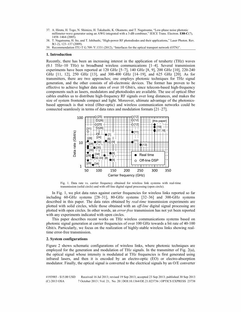
Fig. 1. Data rate vs. carrier frequency obtained for wireless link systems with real-time transmission (solid circle) and with off-line digital signal processing (open circle).
In Fig. 1, we plot data rates against carrier frequencies for wireless links reported so far including 60-GHz systems [28–31], 80-GHz systems [32–36] and 300-GHz systems described in this paper. The data rates obtained by real-time transmission experiments are plotted with solid circles, while those obtained with an off-line digital signal processing are plotted with open circles. In other words, an error-free transmission has not yet been reported with any experiments indicated with open circles.
This paper describes recent works on THz wireless communications systems based on photonic signal generation at carrier frequencies of over 100 GHz towards a bit rate of 40-100 Gbit/s. Particularly, we focus on the realization of highly-stable wireless links showing real-time error-free transmission.
2. System configurations
Figure 2 shows schematic configurations of wireless links, where photonic techniques are employed for the generation and modulation of THz signals. In the transmitter of Fig. 2(a), the optical signal whose intensity is modulated at THz frequencies is first generated using infrared lasers, and then it is encoded by an electro-optic (EO) or electro-absorption modulator. Finally, the optical signal is converted to the electrical signals by an O/E converter
#193985 - $15.00 USD Received 16 Jul 2013; revised 19 Sep 2013; accepted 23 Sep 2013; published 30 Sep 2013(C) 2013 OSA 7 October 2013 | Vol. 21, No. 20 | DOI:10.1364/OE.21.023736 | OPTICS EXPRESS 23738
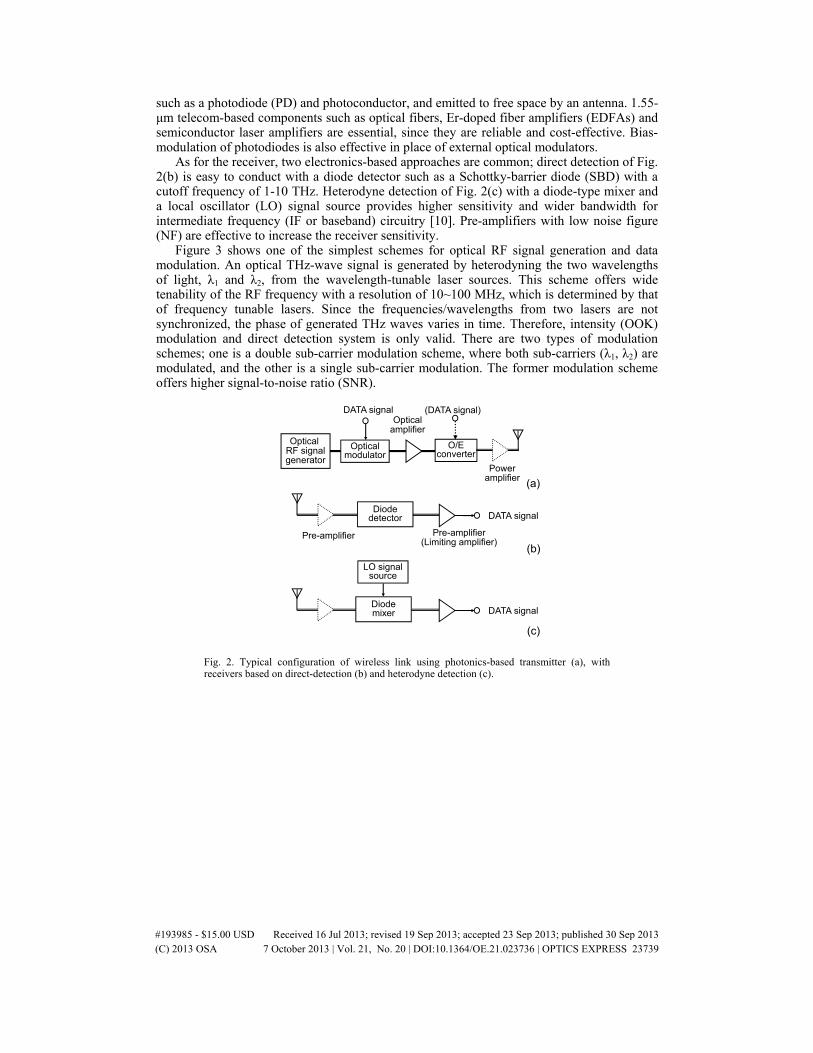
such as a photodiode (PD) and photoconductor, and emitted to free space by an antenna. 1.55-μm telecom-based components such as optical fibers, Er-doped fiber amplifiers (EDFAs) and semiconductor laser amplifiers are essential, since they are reliable and cost-effective. Bias-modulation of photodiodes is also effective in place of external optical modulators.
As for the receiver, two electronics-based approaches are common; direct detection of Fig. 2(b) is easy to conduct with a diode detector such as a Schottky-barrier diode (SBD) with a cutoff frequency of 1-10 THz. Heterodyne detection of Fig. 2(c) with a diode-type mixer and a local oscillator (LO) signal source provides higher sensitivity and wider bandwidth for intermediate frequency (IF or baseband) circuitry [10]. Pre-amplifiers with low noise figure (NF) are effective to increase the receiver sensitivity.
Figure 3 shows one of the simplest schemes for optical RF signal generation and data modulation. An optical THz-wave signal is generated by heterodyning the two wavelengths of light, λ1 and λ2, from the wavelength-tunable laser sources. This scheme offers wide tenability of the RF frequency with a resolution of 10~100 MHz, which is determined by that of frequency tunable lasers. Since the frequencies/wavelengths from two lasers are not synchronized, the phase of generated THz waves varies in time. Therefore, intensity (OOK) modulation and direct detection system is only valid. There are two types of modulation schemes; one is a double sub-carrier modulation scheme, where both sub-carriers (λ1, λ2) are modulated, and the other is a single sub-carrier modulation. The former modulation scheme offers higher signal-to-noise ratio (SNR).
Optical RF signalgenerator
Opticalmodulator
O/Econverter
Opticalamplifier
DATA signal (DATA signal)
(a)
Poweramplifier
DATA signal
Pre-amplifier
Diodedetector
Pre-amplifier(Limiting amplifier)
(b)
(c)
DATA signalDiodemixer
LO signalsource
Fig. 2. Typical configuration of wireless link using photonics-based transmitter (a), with receivers based on direct-detection (b) and heterodyne detection (c).
#193985 - $15.00 USD Received 16 Jul 2013; revised 19 Sep 2013; accepted 23 Sep 2013; published 30 Sep 2013(C) 2013 OSA 7 October 2013 | Vol. 21, No. 20 | DOI:10.1364/OE.21.023736 | OPTICS EXPRESS 23739
Wavelength-tunable laser #1 Optical
modulatorWavelength-tunable laser #2
λ1
λ2
λ1 λ2
λ
Wavelength-tunable laser #1
Opticalmodulator
Wavelength-tunable laser #2
λ1 λ2
λ1
λ2
λ
(a)
(b)
DATA signal
DATA signal
Coupler
to O/E converter
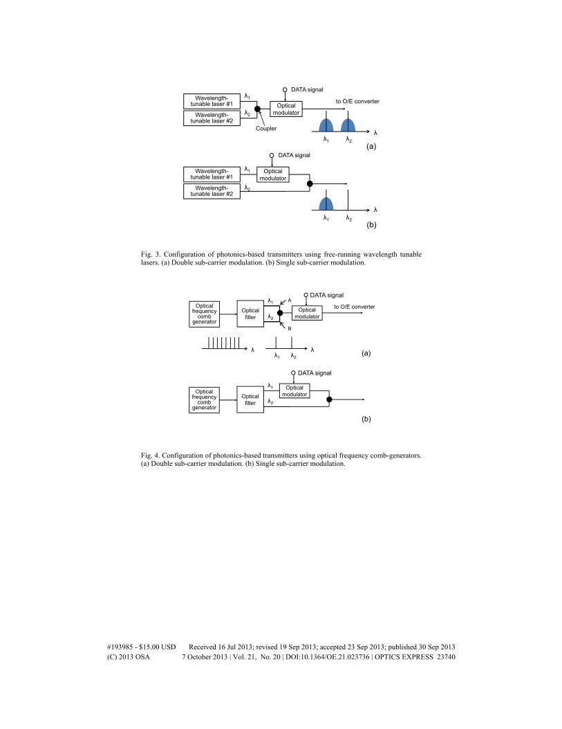
Fig. 3. Configuration of photonics-based transmitters using free-running wavelength tunable lasers. (a) Double sub-carrier modulation. (b) Single sub-carrier modulation.
Optical filter
Opticalfrequency
comb generator
Opticalmodulator
λ1
λ2
(a)
(b)
DATA signal
Opticalmodulator
λ1
λ2
DATA signal
Optical filter
Opticalfrequency
comb generator
λ1 λ2
λλ
to O/E converterA
B
Fig. 4. Configuration of photonics-based transmitters using optical frequency comb-generators. (a) Double sub-carrier modulation. (b) Single sub-carrier modulation.
#193985 - $15.00 USD Received 16 Jul 2013; revised 19 Sep 2013; accepted 23 Sep 2013; published 30 Sep 2013(C) 2013 OSA 7 October 2013 | Vol. 21, No. 20 | DOI:10.1364/OE.21.023736 | OPTICS EXPRESS 23740
1550 nm6 mA
Antenna-integrated
J-band (WR-3 waveguide)
0
-10
-20
-30
-400 200 400 600 800 1000
Frequency (GHz)O
utp
ut p
owe
r (d
Bm
)
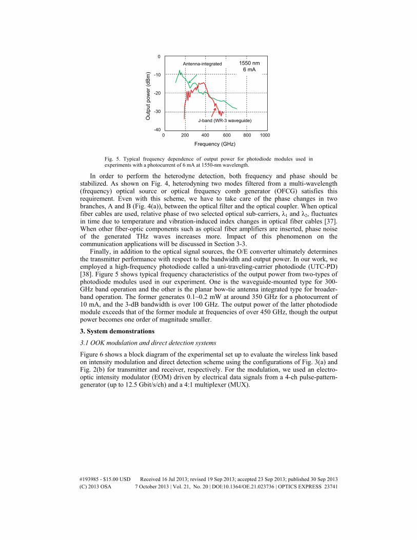
Fig. 5. Typical frequency dependence of output power for photodiode modules used in experiments with a photocurrent of 6 mA at 1550-nm wavelength.
In order to perform the heterodyne detection, both frequency and phase should be stabilized. As shown on Fig. 4, heterodyning two modes filtered from a multi-wavelength (frequency) optical source or optical frequency comb generator (OFCG) satisfies this requirement. Even with this scheme, we have to take care of the phase changes in two branches, A and B (Fig. 4(a)), between the optical filter and the optical coupler. When optical fiber cables are used, relative phase of two selected optical sub-carriers, λ1 and λ2, fluctuates in time due to temperature and vibration-induced index changes in optical fiber cables [37]. When other fiber-optic components such as optical fiber amplifiers are inserted, phase noise of the generated THz waves increases more. Impact of this phenomenon on the communication applications will be discussed in Section 3-3.
Finally, in addition to the optical signal sources, the O/E converter ultimately determines the transmitter performance with respect to the bandwidth and output power. In our work, we employed a high-frequency photodiode called a uni-traveling-carrier photodiode (UTC-PD) [38]. Figure 5 shows typical frequency characteristics of the output power from two-types of photodiode modules used in our experiment. One is the waveguide-mounted type for 300-GHz band operation and the other is the planar bow-tie antenna integrated type for broader-band operation. The former generates 0.1~0.2 mW at around 350 GHz for a photocurrent of 10 mA, and the 3-dB bandwidth is over 100 GHz. The output power of the latter photodiode module exceeds that of the former module at frequencies of over 450 GHz, though the output power becomes one order of magnitude smaller.
3. System demonstrations
3.1 OOK modulation and direct detection systems
Figure 6 shows a block diagram of the experimental set up to evaluate the wireless link based on intensity modulation and direct detection scheme using the configurations of Fig. 3(a) and Fig. 2(b) for transmitter and receiver, respectively. For the modulation, we used an electro-optic intensity modulator (EOM) driven by electrical data signals from a 4-ch pulse-pattern-generator (up to 12.5 Gbit/s/ch) and a 4:1 multiplexer (MUX).
#193985 - $15.00 USD Received 16 Jul 2013; revised 19 Sep 2013; accepted 23 Sep 2013; published 30 Sep 2013(C) 2013 OSA 7 October 2013 | Vol. 21, No. 20 | DOI:10.1364/OE.21.023736 | OPTICS EXPRESS 23741

SBD
Oscillo-scope
MUXPulse
patterngenerator
EDFA
Wavelength tunable laser 1
Wavelength tunable laser 2
LimitingAmplifier
Pre-amplifier
UTC-PD
EOM
Optical filter
DEMUX
Bit error rate
tester
Horn Antenna
Lens
Fig. 6. Schematic diagram of experimental setup to evaluate transmission characteristics of 300-GHz wireless link based on OOK modulation and direct detection.
Photocurrent (mA)6.0 7.0 8.0
Bit
Err
or R
ate
1E-12
1E-10
1E-8
1E-6
1E-4
0.01
5.0
Time
10 ps
(a)
(b)
Fig. 7. Eye diagrams at 40 Gbit/s (a), and bit error rate (BER) characteristics at 40 Gbit/s with a carrier frequency of 300 GHz. Photocurrent (horizontal axis of (b)) is proportional to the square root of the transmitted power.
The modulated optical signal is amplified by the EDFA. An optical filter is inserted to eliminate the amplified spontaneous emission noise from the EDFA. Finally, the optical signals are input to the waveguide-mounted UTC-PD to generate THz waves at 300 GHz, setting the wavelength difference of the two lasers to 2.4 nm. THz waves are radiated from the horn antenna, and dielectric lenses are used to collimate and focus THz waves for the transmitter and receiver, respectively. The total antenna gain is about 40 dBi. The distance between the transmitter and receiver is 0.5~1 m, where there is little change in the received power and a multi-path effect is small.
The data signal is demodulated by the SBD detector which is mounted on WR-2.8 waveguide structure and has a 3-dB IF (baseband) bandwidth and 6-dB bandwidth of 19 GHz and 28 GHz, respectively, at a zero-bias voltage. The responsivity of the SBD detector is 2000 V/W. The SBD detector works based on a square-law detection up to the input power level of 100 μW. The output IF signal is amplified by a broadband pre-amplifier (SHF806E; 40 kHz~38 GHz, 26-dB Gain) and reshaped by a transimpedance amplifier (MICRAM TIA5633; DC~35 GHz) used as a limiting amplifier. The specified timing jitter of the pre-amplifier is 1.25 ps with our 50-GHz sampling oscilloscope.
The performance limitation with respect to the data rate is determined mainly by the bandwidth of the UTC-PD in the transmitter and that of the SBD detector in the receiver. The 3-dB RF bandwidth of the UTC-PD is 140 GHz (from 270 to 410 GHz), while the RF
#193985 - $15.00 USD Received 16 Jul 2013; revised 19 Sep 2013; accepted 23 Sep 2013; published 30 Sep 2013(C) 2013 OSA 7 October 2013 | Vol. 21, No. 20 | DOI:10.1364/OE.21.023736 | OPTICS EXPRESS 23742
bandwidth of the SBD detector also exceeds 100 GHz. Thus, the IF bandwidth of the receiver currently limits the maximum bit rates. Figures 7(a) and 7(b) show eye diagrams demodulated by the receiver and the bit error rate (BER) characteristics at 40 Gbit/s, respectively. Error-free (BER<10−11) transmission has been achieved at 40 Gbit/s, which is the highest data rate ever reported for “error-free” wireless links without forward error correction (FEC). In Fig. 7(b), 8-mA photocurrent of the UTC-PD corresponds to the transmitter output power of 90 μW. Considering a coupling loss between horn antennas including loss at dielectric lenses, about 20-μW power is estimated to be incident to the SBD detector. In this receiver scheme, SNR of the system is mostly determined by the noise figure (NF) of the pre-amplifier after the SBD detector. The specified NF of the amplifier is as large as 6 dB, since this amplifier is originally designed for the modulator driver with high (8-V) output voltages. The pre-amplifier which has much lower NF with a gain of 25-30 dB and an output voltage of 100-mV level is preferable for the receiver.
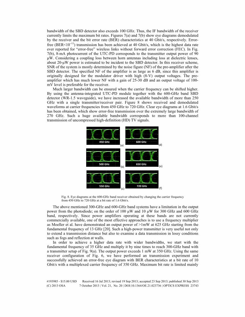
Much larger bandwidth can be ensured when the carrier frequency can be shifted higher. By using the antenna-integrated UTC-PD module together with the 600-GHz band SBD detector (WR-1.5 waveguide), we have increased the available bandwidth of more than 250 GHz with a single transmitter/receiver pair. Figure 8 shows received and demodulated waveforms at carrier frequencies from 450 GHz to 720 GHz. Clear eye diagrams at 1.6 Gbit/s has been obtained, which show error-free transmission over the extremely large bandwidth of 270 GHz. Such a huge available bandwidth corresponds to more than 100-channel transmission of uncompressed high-definition (HD) TV signals.
450 GHz
500 GHz
550 GHz
600 GHz
650 GHz
720 GHz
(a)
(b)
(c)
(d)
(e)
(f)
Fig. 8. Eye diagrams at the 600-GHz band receiver obtained by changing the carrier frequency from 450 GHz to 720 GHz at a bit rate of 1.6 Gbit/s.
The above mentioned 300-GHz and 600-GHz band systems have a limitation in the output power from the photodiode; on the order of 100 μW and 10 μW for 300 GHz and 600 GHz band, respectively. Since power amplifiers operating at these bands are not currently commercially available, one of the most effective approaches is to use a frequency multiplier as Moeller et al. have demonstrated an output power of >1mW at 625 GHz starting from the fundamental frequency of 13 GHz [20]. Such a high-power transmitter is very useful not only to extend a transmission distance but also to examine a data transmission in lossy conditions such as fogs and reflection at walls.
In order to achieve a higher data rate with wider bandwidths, we start with the fundamental frequency of 35 GHz and multiply it by nine times to reach 300-GHz band with a transmitter setup of Fig. 9(a). The output power exceeds 1 mW at 350 GHz. Using the same receiver configuration of Fig. 6, we have performed an transmission experiment and successfully achieved an error-free eye diagram with BER characteristics at a bit rate of 10 Gbit/s with a multiplexed carrier frequency of 350 GHz. Maximum bit rate is limited mainly
#193985 - $15.00 USD Received 16 Jul 2013; revised 19 Sep 2013; accepted 23 Sep 2013; published 30 Sep 2013(C) 2013 OSA 7 October 2013 | Vol. 21, No. 20 | DOI:10.1364/OE.21.023736 | OPTICS EXPRESS 23743
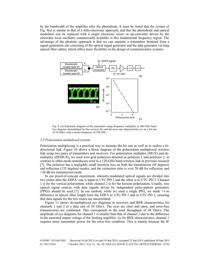
by the bandwidth of the amplifier after the photodiode. It must be noted that the system of Fig. 9(a) is similar to that of a fully-electronic approach, and that the photodiode and optical modulator can be replaced with a single electronic mixer or up-converter driven by the electronic local oscillator commercially available in this fundamental frequency region. The advantage of the photonic approach is that we can separate a transmitter frontend from a signal generation site consisting of the optical signal generator and the data generator via long optical fiber cables, which offers more flexibility in the design of communication systems.
Wavelength-tunable laser #1 Optical
modulatorWavelength-tunable laser #2
λ1
λ2
DATA signal
x 3 x 3PD
27~43 GHz
10-11
10-9
10-7
10-3
10-5
Bit
erro
r ra
te
Photocurrent (mA)2 43
50 ps
(a)
(c)
(b)
Fig. 9. (a) Schematic diagram of the transmitter using frequency multiplier at 300-GHz band. Eye diagram demodulated by the receiver (b) and bit error rate characteristics (c) at a bit rate of 10 Gbit/s with a carrier frequency of 350 GHz.
3.2 Polarization multiplexed systems
Polarization multiplexing is a practical way to increase the bit rate as well as to realize a bi-directional link. Figure 10 shows a block diagram of the polarization multiplexed wireless link using two pairs of transmitters and receivers. For polarization multiplex (MUX) and de-multiplex (DEMUX), we used wire-grid polarizers denoted as polarizer 1 and polarizer 2, in contrast to ortho-mode transducers used in a 120-GHz-band wireless link in previous research [7]. The polarizer has a negligibly small insertion loss on both the transmission (45 degrees) and reflection (135 degrees) modes, and the extinction ratio is over 20 dB for reflection, and >30 dB for transmission mode.
In our proof-of-concept experiment, intensity-modulated optical signals are divided into two routes after the EDFA: one is input to UTC-PD 1 and the other is to UTC-PD 2. Channel 1 is for the vertical polarization, while channel 2 is for the horizon polarization. Usually, two optical signal sources with data signals driven by independent pulse-pattern generators (PPGs) should be used [7]. In our method, while we used a single PPG, we made >1-m difference in optical fiber length from the EDFA to UTC-PD 1 and to UTC-PD 2, ensuring that data signals for the two routes are uncorrelated.
Figure 11 shows de-multiplexed eye diagrams at receivers and BER characteristics for channels 1 and 2 at a data rate of 24 Gbit/s. The eyes are clear and open, and error-free transmissions are confirmed. This corresponds to the total throughput of 48 Gbit/s. The amplitude of eye diagrams for channel 1 is smaller than that of channel 2 due to the difference in the saturated output voltage of the limiting amplifier. As for BER characteristics, channel 1 requires more transmitter power for the error-free condition. This is mainly because the IF
#193985 - $15.00 USD Received 16 Jul 2013; revised 19 Sep 2013; accepted 23 Sep 2013; published 30 Sep 2013(C) 2013 OSA 7 October 2013 | Vol. 21, No. 20 | DOI:10.1364/OE.21.023736 | OPTICS EXPRESS 23744
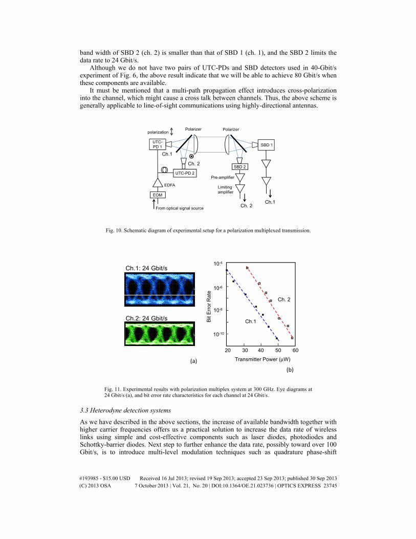
band width of SBD 2 (ch. 2) is smaller than that of SBD 1 (ch. 1), and the SBD 2 limits the data rate to 24 Gbit/s.
Although we do not have two pairs of UTC-PDs and SBD detectors used in 40-Gbit/s experiment of Fig. 6, the above result indicate that we will be able to achieve 80 Gbit/s when these components are available.
It must be mentioned that a multi-path propagation effect introduces cross-polarization into the channel, which might cause a cross talk between channels. Thus, the above scheme is generally applicable to line-of-sight communications using highly-directional antennas.
polarization
SBD 2
EDFA
Pre-amplifier
Limitingamplifier
EOM
UTC-PD 1 SBD 1
UTC-PD 2
Ch. 2
Ch.1
Polarizer Polarizer
Ch. 2Ch.1
From optical signal source
Fig. 10. Schematic diagram of experimental setup for a polarization multiplexed transmission.
20 30 40 50 60
10-10
10-8
10-6
10-4
Transmitter Power (μW)
Bit
Err
or R
ate
Ch.1: 24 Gbit/s
Ch.2: 24 Gbit/s
Ch. 2
Ch.1
(a)(b)
Fig. 11. Experimental results with polarization multiplex system at 300 GHz. Eye diagrams at 24 Gbit/s (a), and bit error rate characteristics for each channel at 24 Gbit/s.
3.3 Heterodyne detection systems
As we have described in the above sections, the increase of available bandwidth together with higher carrier frequencies offers us a practical solution to increase the data rate of wireless links using simple and cost-effective components such as laser diodes, photodiodes and Schottky-barrier diodes. Next step to further enhance the data rate, possibly toward over 100 Gbit/s, is to introduce multi-level modulation techniques such as quadrature phase-shift
#193985 - $15.00 USD Received 16 Jul 2013; revised 19 Sep 2013; accepted 23 Sep 2013; published 30 Sep 2013(C) 2013 OSA 7 October 2013 | Vol. 21, No. 20 | DOI:10.1364/OE.21.023736 | OPTICS EXPRESS 23745
keying (QPSK) and quadrature amplitude modulation (QAM) using coherent THz carrier signals.
Although Pang et al. have examined a wireless link based on multi-level modulation using free-running lasers with a configuration of Fig. 3(b), they have performed an off-line digital signal processing (DSP) to show usefulness of photonically generated QPSK signals, but an error-free transmission has not yet been verified with this approach [21, 25]. To stabilize the carrier frequencies, the optical frequency comb-based signal generation of Fig. 4 is the most effective approach, and Kanno et al. have reported 16-QAM modulation to achieve 40 Gbit/s [22]. Even with this approach, they used the off-line DSP to achieve a BER of ~2x10⁻³, which is the required minimum value to reach an error free transmission with FEC.
Laser
AWGfilter
Piezo
EOM Piezo
EOM
25 GHz
EOM
EOM
Phase stabilizer
Phase stabilizer
12.8 kHz
16 kHz
Optical frequencycomb generator
To photodiodevia modulator
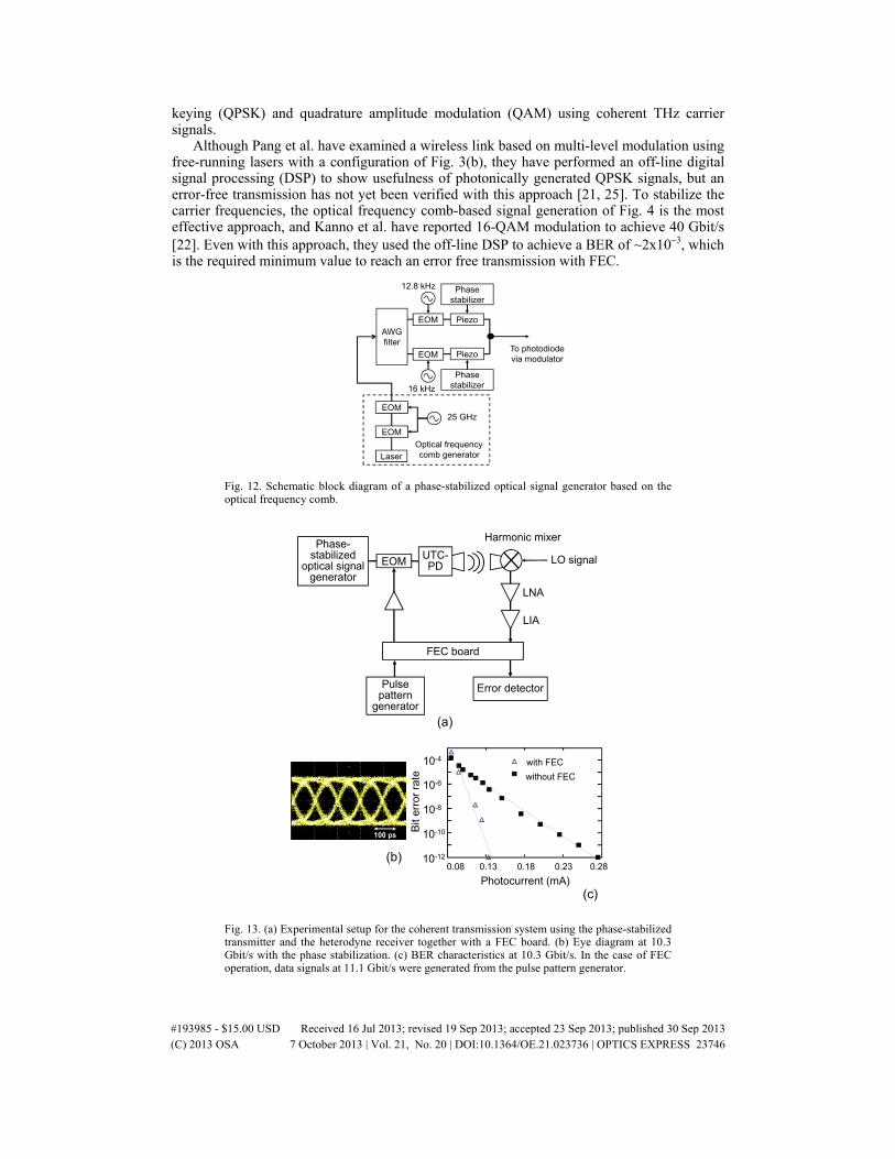
Fig. 12. Schematic block diagram of a phase-stabilized optical signal generator based on the optical frequency comb.
FEC board
Pulse pattern
generator
Error detector
EOMUTC-PD
LNA
LIA
LO signal
Harmonic mixerPhase-
stabilizedoptical signal
generator
(a)
100 ps
(b)
(c)
0.08 0.13 0.18 0.23 0.2810-12
10-10
10-8
10-6
10-4 with FEC
without FEC
Photocurrent (mA)
Bit
erro
r ra
te
Fig. 13. (a) Experimental setup for the coherent transmission system using the phase-stabilized transmitter and the heterodyne receiver together with a FEC board. (b) Eye diagram at 10.3 Gbit/s with the phase stabilization. (c) BER characteristics at 10.3 Gbit/s. In the case of FEC operation, data signals at 11.1 Gbit/s were generated from the pulse pattern generator.
#193985 - $15.00 USD Received 16 Jul 2013; revised 19 Sep 2013; accepted 23 Sep 2013; published 30 Sep 2013(C) 2013 OSA 7 October 2013 | Vol. 21, No. 20 | DOI:10.1364/OE.21.023736 | OPTICS EXPRESS 23746
In order to realize a real-time transmission system based on the multi-level modulation without using complicated DSP techniques, we have investigated the cause of phase instabilities in the optical frequency comb-based scheme, and solved the problem by introducing a phase stabilizer into the two optical paths after the optical filter such as an arrayed waveguide (AWG) filter as shown in Fig. 12. Phase instability between the two optical paths is caused by the change in the index of refraction due to temperature and acoustic noise in the optical fiber cables. Such a noise has a very low frequency component below several tens of hertz, and sometimes shows an unexpected burst-like behavior. To measure and control such a phase noise, we applied dither signals at frequencies around 10 kHz to each path with EOM, and compensated the phase fluctuation with Piezo phase shifters by the feedback circuits. The dither frequency should be chosen not to affect the data transmission.
To verify the importance of phase stabilization in the frequency comb-based transmitter, we conducted a coherent transmission experiment with a carrier frequency of 100 GHz as shown in Fig. 13(a). As for the receiver, we used a sub-harmonic mixer driven by a local oscillator (LO) signal at 50 GHz. In addition, we applied an FEC board to know whether the FEC is effective or not with or without the phase stabilizer. The FEC board is a standard one based on the Reed-Solomon codes [39].
Figure 13(b) shows an eye diagram after the receiver at a data rate of 10.3 Gbit/s with the phase stabilization. Without the stabilization, we could not observe clear eye diagrams at all. We measured BER characteristics with and without the FEC as shown in Fig. 13(c). It has been confirmed that the FEC properly works with our phase-stabilized transmitter. However, we could not measure BER without the phase stabilization; the bit error rate tester indicated “synchronous error”. Thus, the phase stabilization is necessary to achieve a real-time data transmission even with the FEC.
4. Conclusion
To explore undeveloped THz-wave regions for wireless communications, photonic signal generation is the most powerful technique, and particularly, the approach with use of telecom-based components is not only a technology driver in the wireless communications, but also makes it easy to combine the wireless link with fiber-optic networks seamlessly.
In this paper, we have demonstrated real-time error-free transmission at a carrier frequency of 300 GHz with the highest data rate up to 40 Gbit/s and 48 Gbit/s for a single channel and polarization multiplexed channel, respectively, and 50 Gbit/s and 100 Gbit/s are feasible for each approach by improving the bandwidth of the baseband circuitry of the detector. We have also described a 600-GHz band system to show that available bandwidth can be doubled to ensure higher data rate, and a frequency-multiplied transmitter to increase the output power of the transmitter to 1 mW and higher. Finally, in order to apply multi-level modulation schemes to the real-time transmission with much higher data rate of over 100 Gbit/s, we have proposed the phase-stabilized transmitter based on the optical frequency comb, and a proof-of-concept experiment has been successfully conducted at a carrier frequency of 100 GHz.
Recently, THz amplifiers such as power amplifiers and pre-amplifiers for transmitters and receivers, respectively, have started to be developed even with Si technologies. Use of such amplifiers would make the photonics-based THz wireless technology more practical. One of the future directions of photonics-based approaches should be an integration of photonic devices as well as electronic devices using contemporary fabrication technologies such as silicon photonics to make THz transceivers more compact and cost-effective.
#193985 - $15.00 USD Received 16 Jul 2013; revised 19 Sep 2013; accepted 23 Sep 2013; published 30 Sep 2013(C) 2013 OSA 7 October 2013 | Vol. 21, No. 20 | DOI:10.1364/OE.21.023736 | OPTICS EXPRESS 23747