tender no. 51403 for the supply and maintenance of ... and maintenance of double deck electric...
TRANSCRIPT

Procurement & Contracting Division
Electrification Project
Supply and Maintenance of Double Deck Electric Multiple Units
VOLUME B – Technical Specifications Page 1 of 143 Tender 51403
TENDER No. 51403
for
the Supply and Maintenance of
Electric Multiple Units
Volume B
Technical Specifications
March 16th
, 2016

ISRAEL RAILWAYS LTD. REQUEST FOR PROPOSALS
Supply and Maintenance of Double Deck Electric Multiple Units
VOLUME B – Technical Specifications Page 2 of 143 Tender 51403
Table of Contents
0 Introduction 15
1 General Requirements 16
1.1 Operational Characteristics 16 1.1.1 Vehicle Concept 16
1.2 Design Targets 17
1.3 Climatic Conditions 19
1.4 Applicable Standards 19
1.5 Characteristics of the Unit 20 1.5.1 Basic Technical Data 20 1.5.2 UIC Track Classification 22 1.5.3 Additional Requirements 22 1.5.4 Start-up-/ Shutdown Procedure 22 1.5.5 Operation Modes 23 1.5.5.1 Parking Mode 23 1.5.5.2 Washing Operating Mode 23 1.5.5.3 Emergency Operation 24
1.6 Vehicle Gauge 24
1.7 Vehicle Weight 24
1.8 Infrastructure 25 1.8.1 General 25 1.8.2 Platform Height and Length 25 1.8.3 Tunnels 25 1.8.4 Line and Track Parameter 25
1.9 Noise Emissions 26 1.9.1 General 26 1.9.2 Interior Noise Passenger Compartment 26
1.10 Pressure Protection, Aerodynamic 26
1.11 Running Safety and Running Dynamics 27 1.11.1 General 27 1.11.2 Running Dynamics Calculations 27 1.11.3 Dynamic Testing 27 1.11.4 Comfort of Ride 27
1.12 Electromagnetic Compatibility 27
1.13 Interference with Signalling and Telecommunication Systems 28
1.14 Health and Safety Impact of EMF on Passengers/ Train Crews 28
1.15 Precautions against Pollution, Damage and Water 29
2 Mechanical and Pneumatic Equipment 30
2.1 General Design Principles 30
2.2 Carbody 30 2.2.1 Design 31

ISRAEL RAILWAYS LTD. REQUEST FOR PROPOSALS
Supply and Maintenance of Double Deck Electric Multiple Units
VOLUME B – Technical Specifications Page 3 of 143 Tender 51403
2.3 Running Gear 31 2.3.1 General 31 2.3.2 Structural Design of Bogie Frame 31 2.3.3 Wheel Set and Journal Bearings 32 2.3.4 Sanding System 33 2.3.5 Flange Lubrication 33
2.4 Coupling Devices 34 2.4.1 Automatic Coupling Devices at the front Ends 34 2.4.1.1 Emergency Coupler 34 2.4.2 Coupling Device in-between Vehicles 35 2.4.3 Gangways / Gangway Facilities 35
2.5 Driver’s Cab 35 2.5.1 Design 35 2.5.2 Driver’s Seat 36 2.5.3 Driver’s Desk and Operating Elements 36 2.5.4 Driver’s Cab Access 37 2.5.5 Visibility 37 2.5.6 Windscreen and Equipment 37 2.5.7 Side Windows, Destination Sign Windows and Rear-View Device 38 2.5.8 Lighting 38 2.5.9 Comfort Features (Thermo-Box, Wardrobe) 39 2.5.10 Emergency Equipment 39
2.6 Vehicle Interior Design 39 2.6.1 General 39 2.6.2 Passenger Areas 40 2.6.3 Vehicle Capacity, Arrangement of Seats and Tables 41 2.6.4 Vestibule Areas 41 2.6.5 Sanitary Facilities 42 2.6.5.1 General 42 2.6.5.2 Standard Toilet 42 2.6.5.3 Toilet for People with reduced Mobility 42 2.6.6 Multi-Purpose-Area 43 2.6.7 Bistro 43 2.6.8 Roller Blinds 43 2.6.9 Ceiling 43 2.6.10 Floor 43 2.6.11 Interior Stairs 44 2.6.12 Interior Lighting Equipment 44 2.6.13 Baggage Racks 44 2.6.14 Electric Outlets for Utilities 44 2.6.15 Emergency Equipment 45
2.7 Windows 45 2.7.1 General 45 2.7.2 Passenger Side Window 45 2.7.3 Door Windows 45 2.7.4 Emergency Exit Window 45
2.8 Doors and Entrances 45 2.8.1 General 45 2.8.2 Door Control 46 2.8.3 Opening of Doors 46 2.8.4 Closing of Doors 46 2.8.5 Emergency Opening 46 2.8.6 Obstruction Detection 47 2.8.7 Door Isolation 47 2.8.8 Surveillance of open Doors 47

ISRAEL RAILWAYS LTD. REQUEST FOR PROPOSALS
Supply and Maintenance of Double Deck Electric Multiple Units
VOLUME B – Technical Specifications Page 4 of 143 Tender 51403
2.8.9 Internal Passenger Doors 47
2.9 Brake System 47 2.9.1 Magnetic Track Brake 49 2.9.2 Brake Calculation 49 2.9.3 Calculation of Thermal Capabilities 50 2.9.4 Requirements with regard to ISR Network 50 2.9.5 Compressed Air Supply 50
2.10 Visual and Acoustic Signalling System and Lighting 51 2.10.1 Exterior Lighting 51 2.10.1.1 Lamp Controls 51 2.10.2 Acoustic Signalling 52
2.11 Painting, Labelling and Corrosion Protection 52
2.12 Air Conditioning 53 2.12.1 General 53 2.12.2 HVAC System for the Passenger and Entrance Area 53 2.12.2.1 Control System 54 2.12.3 HVAC System of the Driver’s Cab 55
3 Electric Equipment 56
3.1 Traction System Concept 56
3.2 Primary Voltage Circuit 57 3.2.1 Power Supply and Overhead Line System 57 3.2.2 Pantographs, Main Switches, Roof Cables and Earthing Switches 57 3.2.2.1 Automatic Power Control System to support the passing of a the neutral Zone 59 3.2.3 System Perturbation and Energy Counter 59 3.2.4 Transformer 59
3.3 Propulsion System 60 3.3.1 Power Converter 60 3.3.2 Electric Brake 60 3.3.3 Traction Motor and Gear 61 3.3.4 Propulsion Control 61
3.4 DC On-board Network 61 3.4.1 General 61 3.4.2 Batteries 62 3.4.3 Battery Charger 62
3.5 On Board Power and Auxiliary Power Supply 62
3.6 Cooling / Ventilation Technical Cabinets 63
3.7 External Power Supply 63
3.8 Train Control Monitoring System (TCMS) 64 3.8.1 General 64 3.8.2 Software 64 3.8.3 Control Levels within the Trainset 65 3.8.4 Diagnosis and Control Functions 65 3.8.5 Speed Measurement 66 3.8.6 Drive / Brake-Control 66 3.8.7 Automatic Speed Control 66 3.8.8 Adhesion Control 66 3.8.9 Automatic Brake Test 67 3.8.10 Multiple Unit Control 67
3.9 Diagnostic / Fault System 67

ISRAEL RAILWAYS LTD. REQUEST FOR PROPOSALS
Supply and Maintenance of Double Deck Electric Multiple Units
VOLUME B – Technical Specifications Page 5 of 143 Tender 51403
3.9.1 General 67 3.9.2 Structure of the Diagnostic System 68 3.9.2.1 Train / Vehicle Diagnostic (central Diagnostic) 68 3.9.2.2 Diagnosis of Subsystems 70 3.9.2.3 Condition Monitoring 70 3.9.2.4 Isolation of defective Parts 71 3.9.2.5 Quality of the Diagnostics 71 3.9.2.6 Tools, Maintenance Support System 71
3.10 Accessibility of Indicators and Control Elements 72
3.11 Safety devices 72 3.11.1 Automatic Train Protection & Control Systems 72 3.11.2 Driver's Safety Device (DSD) 73 3.11.3 Emergency Warning Provisions 73
3.12 Train Radio 73
3.13 Passenger Information System 73 3.13.1 General 73 3.13.2 Visual Information Facilities 74 3.13.3 Audible Information Facilities 74 3.13.4 Passenger Emergency Communication 75
3.14 Communication Facilities 75 3.14.1 Mobile Communication 75 3.14.2 Internet Communication 76
3.15 Passenger Counting System 76
3.16 Passenger Reservation System 76
3.17 Interior CCTV System 76
4 Design and Workmanship 77
4.1 Mechanical Equipment 77
4.2 Electric Equipment 77
5 RAMS 78
5.1 General 78
5.2 System Assurance Plan 78
5.3 Demonstration of Reliability, Availability, and Maintainability 78
5.4 Reliability Requirements 79 5.4.1 Reliability Performance 79
5.5 Availability Requirements 82 5.5.1 Availability 82 5.5.2 Maintainability Requirements 83 5.5.3 Maintainability Performance 84
5.6 Safety 85
5.7 LCC Analysis 86
6 Maintenance 88
6.1 General Issues 88
6.2 Modular Design 88

ISRAEL RAILWAYS LTD. REQUEST FOR PROPOSALS
Supply and Maintenance of Double Deck Electric Multiple Units
VOLUME B – Technical Specifications Page 6 of 143 Tender 51403
6.3 On-Board Tools and Accessories 88
7 Fire Protection 90
7.1 General Issues 90
8 Environment Protection and Ecology 91
9 Design, Development and Technical Documentation 92
9.1 General 92
9.2 Project Control Plan 92
9.3 Progress reports during Production Phase 92
9.4 Technical Documentation 92
9.5 Configuration Control 93 9.5.1 General 93 9.5.2 Technical Documentation 93 9.5.3 Records 93 9.5.4 Submittal of changed Documents 94
9.6 Development and Design Approval 94
9.7 Documents with the Start Point of Manufacturing Inspection 94 9.7.1 General 94 9.7.1.1 Mechanical Drawings 95 9.7.1.2 Calculations 95 9.7.1.3 Electrical system documents 95 9.7.1.4 Data Sheets 95
9.8 Documents to be Submitted Before Acceptance of the Unit 96 9.8.1 General Specification of the Unit type 96 9.8.2 Manuals 96 9.8.3 Documentation and manuals concept 96 9.8.4 Operating Instructions - Driver’s Manual 96 9.8.5 Maintenance Documentation and Procedures 97 9.8.5.1 Maintenance Principle and Methods 97 9.8.5.2 Maintenance Strategy 97 9.8.5.3 Maintenance Tasks Description 98 9.8.6 Illustrated Part Catalogue 98 9.8.6.1 Parts Breakdown 99 9.8.6.2 Part Numbers Index 99 9.8.7 Document delivery format 99
9.9 Interactive Electronic Technical Manual – IETM 100
9.10 Lubrication Charts 100
10 Operation and Maintenance Training 102
10.1 General 102
10.2 Class Room Training 103
10.3 On-the Job Training 103
10.4 Maintenance Instruction 103 10.4.1 Class Room Training 103 10.4.2 On-the Job Training 104 10.4.3 Duration and Location for Training 104

ISRAEL RAILWAYS LTD. REQUEST FOR PROPOSALS
Supply and Maintenance of Double Deck Electric Multiple Units
VOLUME B – Technical Specifications Page 7 of 143 Tender 51403
11 Technical Support 105
12 Warranty of the Supplier 106
13 Manufacturing Record Book MRB 107
14 Acceptance Test 108
15 Fault-free Running 109
16 Supplier's Maintained Fleet – General Provisions 109
16.1 General 109
16.2 Key Objectives of the Rolling stock maintenance under the Supplier’s provision109
16.3 Maintenance Quantities 110
16.4 Maintenance Concept 110
16.5 Scope of Maintenance Work 111
16.6 Maintenance Contract Duration 111
16.7 Management Task Preparation 111
16.8 Maintenance Work Execution 112 16.8.1 Mobile Maintenance Service 112 16.8.2 Stationary Work Execution at Maintenance Depot 112
16.9 Depot Development 112 16.9.1 Depot Facility and Equipment Delivery 113 16.9.2 Maintenance Workflow 113 16.9.3 Depot Maintenance Arrangement and Capacity 113
16.10 Maintenance Material and Spare Parts Management 114
16.11 Maintenance Engineering and Reporting 115 16.11.1 Units Technical Documentation 115 16.11.2 Maintenance Management Information System (MMIS) and Maintenance Records 115 16.11.3 Manufacturing Record Book 115
16.12 Maintenance Planning and Corrective Action Advise 116
16.13 Maintenance Contract Performance Indicator 116

ISRAEL RAILWAYS LTD. REQUEST FOR PROPOSALS
Supply and Maintenance of Double Deck Electric Multiple Units
VOLUME B – Technical Specifications Page 8 of 143 Tender 51403
Appendixes
A Appendix A: Rail Types, Lines and Track Quality 118
A.1 Rail Types 118
A.2 General Criteria for Track Maintenance 118
A.3 Line and Track Parameters 119
A.4 Platforms Dimension and Data 120
B Appendix B: Specification of the Trip Time Calculation 123
B.1 Methodology 123
B.2 Horizontal plan 125
B.3 Vertical plan 126
B.4 Speed Profile: 128
C Appendix C: Running Dynamics 129
D Appendix D: Environmental Conditions 130
D.1 Climate and Environmental Conditions 130
D.2 Dust Concentrations in the Atmosphere 130
D.3 Sea Salt Concentrations in the Atmosphere 130
E Appendix E: Water Quality 131
F Appendix F: Air Conditioning Performance 132
F.1 HVAC Passenger Area 132
F.2 HVAC Driver’s Cab 138
G Appendix G: System Requirements 140
G.1 System layout 140
G.2 Distances between Passenger Stations 141
H Appendix H: Technical Requirements for Electronic Equipment 142
H.1 Ambient Temperature (supplementary to EN 50155, Paragraph 2.1.2) 142
H.2 Special Service Conditions (supplementary to EN 50155, Paragraph 2.2) 142
H.3 Testing 142

ISRAEL RAILWAYS LTD. REQUEST FOR PROPOSALS
Supply and Maintenance of Double Deck Electric Multiple Units
VOLUME B – Technical Specifications Page 9 of 143 Tender 51403
Glossary:
Abbreviation Explanation
AAR Association of American Railroads
AC Alternating current
a/c Air conditioning
AFB Automatic Drive-Brake-Control
ATC Automatic Train Control
ATP Automatic Train Protection
CAN bus Controller Area Network bus
CCITT Commité Consultatif Internationale Télégrafique et Téléfonique
CCTV Closed-Circuit Television System
DC Direct current
DD Double-Deck
Unit Double Deck Electrical Multiple Unit
DDHC Double-Deck Handicapped Coach equipped for handicapped passengers
DDPC Double Deck Pilot Coach
DDTC Double-Deck Trailer Coach
DMA Direct Memory Access
DMI Driver Machine Interface
EBO Regulations for Railway Construction and Operation in Germany
EMC Electromagnetic compatibility
EMF Electromagnetic Field
EN European Norm
EP-brake Electro-pneumatic Brake
ETCS European Train Control System
FKM
GPS
Guidelines for calculated stress analysis for machine components
Global Positioning System
HMI Human-Machine Interface
HPL High Pressure Laminated Linings
HVAC Heating, Ventilation, Air conditioning
H.V. Network High Voltage network
IEC International Electrotechnical Commission
ISRAEL RAILWAYS LTD. REQUEST FOR PROPOSALS
Supply and Maintenance of Double Deck Electric Multiple Units
VOLUME B – Technical Specifications Page 10 of 143 Tender 51403
Abbreviation Explanation
IETM Interactive Electronic Technical Manual
IGBT Insulated Gate Bi-polar Transistor
ISO International Organization for Standardization
IS Israeli Standard
ISR Israel Railways Ltd.
ITU International Telecommunication Union
LAHT Low Alloy High Tensile
LCC Life Cycle Costs
LED Light-Emitting-Diode
LZB Continuous Automatic Train Control System with Cab Signalling
MBP Main Brake Pipe
MB Data Sheet
MDBF Mean Distance Between Failures
MDBSF Mean Distance between Sub-System-Service-Failures
MDT Mean Down Time
MG-brake Magnetic Track Brake
MOT Israeli Ministry of Transportation
MSL Mean Sea Level
MTBF Mean Time between Failures
MTTM Mean Time To Maintain
MTTR Mean Time To Repair
MRB Manufacturing Record Book
MU Multiple Unit
Same as “trainset”
MVB Multifunction Vehicle Bus
NTP Notice to Proceed; Date, on which the Supplier receives the notice to proceed
from ISR
PAS Passenger Alarm System acc. to UIC 541-6
PA-System Public Address System
PIS Passenger Information System
PP Push-Pull

ISRAEL RAILWAYS LTD. REQUEST FOR PROPOSALS
Supply and Maintenance of Double Deck Electric Multiple Units
VOLUME B – Technical Specifications Page 11 of 143 Tender 51403
Abbreviation Explanation
RAM Reliability – Availability – Maintainability
RAMS Reliability – Availability – Maintainability - Safety
RIC Agreement for the exchange and use of coaches in international traffic (RIC)
RT Railtrack Standards, UK
SD Single-Deck
SDPP Single Deck Push Pull trailer coach
SDPP-PC Single Deck Push Pull Pilot Coach
SPM Suspended Particle Matter
TCN Train Communication Network, according to IEC 61375
TEN Trans European Network
TL Technical Conditions for Supply of Goods and Services, DB AG
TOC Table of Contents
TOR Top of Rail
TSI Technical Specification for Interoperability
UIC Union Internationale de Chemins de Fer
VDE Federation for Electrical and Electronic Engineering and Computer Science,
Germany
WTB Wire Train Bus

ISRAEL RAILWAYS LTD. REQUEST FOR PROPOSALS
Supply and Maintenance of Double Deck Electric Multiple Units
VOLUME B – Technical Specifications Page 12 of 143 Tender 51403
Definitions
Expression Explanation
ALARP As Low As Reasonably Practicable
Adhesion Coefficient of: During rolling contact, the ratio between the longitudinal
tangential force at the wheel-rail interface and normal force.
Approved Where approval is required the Supplier must apply for specific written
review and must receive specific written approval from the ISR.
Availability The percentage of fleet vehicles readily available for service at any
given time.
Disk Braking Friction brake effort produced by the spring applied / electrically-
released brake system.
Driver Israel Railways personnel responsible for vehicle and train operation,
used synonymously with "Operator".
Dynamic Brak-
ing
Braking effort produced by traction motors.
Emergency
Braking
Combined braking effort produced by dynamic braking, disk braking
and magnetic track braking.
Friction Brak-
ing
The brake effort produced by disc braking and magnetic track braking.
Indusi Inductive Train Control System
Interface The points where two or more subsystems, systems, persons or firms
must meet to assure continuity of the project.
Jerk Time rate of change of acceleration and deceleration, equal to the
second derivative of velocity. The normal units are meters per second
cubed.
Multiple Opera-
tion
Trainsets are designed so that several of them can be coupled to-
gether to be operated as one single train.

ISRAEL RAILWAYS LTD. REQUEST FOR PROPOSALS
Supply and Maintenance of Double Deck Electric Multiple Units
VOLUME B – Technical Specifications Page 13 of 143 Tender 51403
Expression Explanation
Multiple Unit Self-propelled trainset consisting of several vehicles which have pas-
senger capacity each.
Operator Used interchangeably with vehicle driver
prove
proved
proven
The Bidder and/or Supplier, as applicable, must provide evidence that
the requirement is fulfilled, respectively a description of the method
used to verify that the requirement is fulfilled.
Redundancy The existence in a system of more than one means of accomplishing a
given function.
Reliability The probability of performing a specified function, without failure in re-
lation to a reference time period intended under actual operating con-
ditions.
Service Braking Normal variable braking effort available to the operator through the
use of the master controller resulting from a combination of dynamic
and friction brakes.
Slide, Wheel During braking, the condition existing when the rotational speed of the
wheel is less than that for pure rolling.
Slip, Wheel During acceleration, the condition existing when the rotational speed
of the wheel is greater than that for pure rolling.
Slip/Slide Syst. System used to direct and correct wheel slide and wheel slip.
Subsystem A subsystem is any of the major hardware groupings which in combi-
nation form a complete vehicle. The subsystems are carbody, bogies,
propulsion system, friction brake system, air-comfort system.
Magnetic Track
Brake
Electro-magnetic braking device used during emergency braking, in-
dependent from the coefficient of friction between wheel and rail.
Train A train is composed of one or more units. If a train is composed of
more than one unit, the units are mechanically and electrically coupled
and the control of the train is performed from one drivers cabin.

ISRAEL RAILWAYS LTD. REQUEST FOR PROPOSALS
Supply and Maintenance of Double Deck Electric Multiple Units
VOLUME B – Technical Specifications Page 14 of 143 Tender 51403
Expression Explanation
Unit Shall mean a Short Unit and/or a Long Unit, whether ordered under
the Initial Purchase Order or under an Additional Purchase Order in
accordance with the terms and definitions of Tender Documents.
Vehicle A vehicle is the smallest part in a Unit (=single vehicle); it features an
individual body shell lying on its own sets of wheels or sharing them
with adjacent vehicles.

ISRAEL RAILWAYS LTD. REQUEST FOR PROPOSALS
Supply and Maintenance of Double Deck Electric Multiple Units
VOLUME B – Technical Specifications Page 15 of 143 Tender 51403
0 Introduction
This Technical Specification describes the requirements for design, technical performance, manu-
facture, delivery and maintenance of new Double Deck Electrical Multiple Short and Long Units
(Unit) for Israel Railways. A mixed configuration of SD and DD vehicles of a proven design solution
by Bidders will also be accepted. This specification describes ISR’s requirements concerning the
characteristics and equipment of an Unit with an electric propulsion system running on a new build
25 kV, 50 Hz catenary system in Israel. This overhead network system is currently under construc-
tion.
In the Technical Proposal, all articles of this Technical Specifications shall be explicitly, definitely,
traceably and fully responded in writing (tabular form preferred) in the same order as in this Speci-
fication. Relevant drawings, sketches, curves or other technical documentation shall be highlighted
in the written respond and completely enclosed.
Bidder shall offer a Unit which is based on a proven design and meets the specified requirements.
The Technical Proposal shall include the maintenance of the Unit over a defined service period as
specified in the Agreement in section 19.2 . The realisation how these requirements are fulfilled
shall be explained in the Technical Proposal.
Bidder must fulfil all the requirements of the Technical Specifications. Nevertheless, the Bidder
may propose alternative solution which provides the same or better level of performance. In any
event ISR is not obliged to accept the alternative provision.
ISRAEL RAILWAYS LTD. REQUEST FOR PROPOSALS
Supply and Maintenance of Double Deck Electric Multiple Units
VOLUME B – Technical Specifications Page 16 of 143 Tender 51403
1 General Requirements
1.1 Operational Characteristics
The Unit shall be designed for universal operation on the electrified tracks of the ISR network.
The Unit shall be bi-directional vehicle with driver cabs on both ends.
A train speed of 160 km/h shall be reached under maximum load and operation conditions.
The Unit is used in regional service as well as for intercity comparable passenger traffic. The jour-
ney distances are varied from a few kilometres up to about 300 km. The distance between the sta-
tions can be as short as 2 km.
The Unit shall provide full performance operation under the environmental conditions in Israel.
The Unit shall be suitable for a daily average operation time of at least 18 hours with a running
performance of 175 000 km / year with scheduled maintenance according to the Supplier’s instruc-
tions.
The Supplier has the sole responsibility to observe and comply with all relevant functions and pa-
rameters which are required for safe and reliable operation within ISR.
Operation and monitoring of the Unit by a single driver shall be warranted.
1.1.1 Vehicle Concept
Two different configurations of Unit shall be offered according to this technical specification:
The Short Unit shall be composed of
Unit consisting of 4 vehicles with an adequate number of motor vehicles to meet traction
power performance requirements
One vehicle meeting the requirements for the transport of wheel chair users according to
TSI PRM;
Driver's cabs on both ends of the unit.
The Long Unit shall be composed of
Unit consisting of 6 vehicles with an adequate number of motor vehicles to meet traction
power performance requirements
One vehicle meeting the requirements for the transport of wheel chair users according to
TSI PRM;
One vehicle shall be equipped with a bistro section for passenger service;
Driver's cabs on both ends of the unit.

ISRAEL RAILWAYS LTD. REQUEST FOR PROPOSALS
Supply and Maintenance of Double Deck Electric Multiple Units
VOLUME B – Technical Specifications Page 17 of 143 Tender 51403
Both configuration types shall be designed so that the units have an optimum of possible redun-
dancy, especially for the traction and auxiliary system as well as the train control. Respective stud-
ies shall be provided in the offer. The different types of vehicles within the unit shall be minimized
while a maximum level of unification regarding interchangeability of vehicles, parts and consum-
ables shall be envisaged.
The Unit's shall be designed in a way that
The Short Unit can be extend by an additional vehicle
The Long Unit can be extend by an additional vehicle.
The two ends of the unit shall feature an automatic coupler, allowing the mechanical, electrical and
pneumatic coupling without the necessity for manual assistance. Coupling shall be easily possible
during normal operation (see chapter 2.4.1).
The following configuration in multiple unit operation shall be possible in revenue service:
up to three (3) Short Units
Up to two (2) Long Units
One (1) Long Unit plus up to two (2) Short Units
Operational flexibility in regard to coupling different units to an train set consist shall consider the
utilization opportunity of the max station platform length of 325 m.
1.2 Design Targets
The vehicles shall be designed according to the current state-of-the-art and have to fulfil the re-
quested requirements of the Technical Specification for Interoperability TSI LOC PAS.
Design verification shall be demonstrated by stress analysis, engineering calculations, comparative
analysis and tests. The following chapter outlines the minimum design criteria and applicable stan-
dards. The list of applicable standards shall be prepared by the Supplier during the design process.
Design and construction of the offered Units have to fulfil best practice quality standards and cor-
responding references shall be provided.
Following summary of general design topics shall be ensured:
Passenger friendly seat configuration and alignments, sufficient aisle width and a modern
and clean compartment interior design
Provision of sufficient space for person with reduced mobility, bicycles, baby carriage and
luggage
Provision of real time passenger information, communication systems and emergency
signalisation systems

ISRAEL RAILWAYS LTD. REQUEST FOR PROPOSALS
Supply and Maintenance of Double Deck Electric Multiple Units
VOLUME B – Technical Specifications Page 18 of 143 Tender 51403
As best as possible barrier free clearance between ISR’s station platforms and Unit
entrance area and at the Unit interior including toilet access
All applicable safety standards shall be met
The Unit shall be reliable and energy-efficient on the ISR’s operation conditions
The Unit shall support the interference-free feeding back of break energy into the public
power grid via the catenary system
The arrangement of equipment and assemblies shall allow easy access in case of repair
and maintenance
Sufficient and easy access to all major components and assemblies at the whole
Unit (e.g. drivers’ cabs, equipment cabinets, roof sections, underfloor area) shall be en-
sured
It shall be possible to lift out large assemblies preferably upwards through easily removable
roof hatches and side walls
Forklifting shall be used for lateral removal of components or modules
To avoid electrical hazards in relation to any handling or work at the Unit a safe grounding
regime covering all electrical components of the Unit shall be provided
Identical components, equipment, and assemblies must be interchangeable without restric-
tions between the Units
Standard components and fasteners shall be applied as far as possible
The need of special tools and equipment shall be minimized
Considering the requirements of environment protection and the state-of-the-art, the Unit shall be
integrally optimised according to the following design targets (most important first):
Overall passenger comfort satisfaction, passenger seat friendly configuration and align-
ments and seating capacity optimized
Minimum maintenance effort
Maximum reliability and high availability
Maximum total efficiency including energy recuperation
Optimum running quality and low track stress impact
Optimum transmission of tractive effort between wheel and rail in the entire speed range
Low noise emission according to the applicable standards
Ergonomically well designed driver’s cab

ISRAEL RAILWAYS LTD. REQUEST FOR PROPOSALS
Supply and Maintenance of Double Deck Electric Multiple Units
VOLUME B – Technical Specifications Page 19 of 143 Tender 51403
1.3 Climatic Conditions
For the functionalities of the Unit and its components and parts, the climatic conditions which are
listed below have to be respected (see also Appendix D.1):
Range of ambient temperatures: -5 °C to +45 °C (with temperature changes of up
to 20°C per hour)
Altitude of operations: -400 m to +800 m above MSL
Cross winds: 5 m/s with gusts of wind of 50 m/s in duration of
1s per gust of wind
Snowfall no particular requirements
Rainfall 400-800 mm/years
Relative humidity: 10% to 90%
UV radiation 360-600 MJ/m² per year
Sunny hours per year: 3300 h
Contamination of the atmosphere: refer to Appendix D2
Sea salt concentration in the atmosphere: refer to Appendix D3
It is specifically emphasised that no performance degradation shall result from any “worst case”
combination of the environmental conditions defined in this specification.
Special attention shall be paid to the local sunlight intensity and resulting heat transfer by radiation.
1.4 Applicable Standards
All applicable laws, standards and rules shall be met with respect to the order as listed below, even
if they are not explicitly listed in this Technical Specification. In general and related to the publica-
tion date of the tender the latest published versions of the dedicated standards and rules are to be
used.
The applied laws, standards and rules applicable to each section shall be explained in the bid.
Generally the most restrictive requirements as given by law, standard or rule shall be applied.
In cases of contradictions between any of the above mentioned laws, standards or rules, the most
superior requirement according to the hierarchy below shall be applied.
The design and production of the offered Unit must be in compliance with the applicable standards
of the following hierarchically listed standard families (descending order):

ISRAEL RAILWAYS LTD. REQUEST FOR PROPOSALS
Supply and Maintenance of Double Deck Electric Multiple Units
VOLUME B – Technical Specifications Page 20 of 143 Tender 51403
1. Israeli Legislation, ISR homologation demands
2. Israel Technical Rules, Norms and Standards
3. TSI
4. EN/IEC Norms and Standards
5. UIC Leaflets
6. Other norms and standards
For the removal of doubt the design requirement in regard to the fire safety relevant standard ap-
proach will be as described in Chapter 6.
Even if applicable standards are mentioned in the individual sections of this specification it is to be
noted that such references or listings are not exclusive.
If changed or new standards come into force after award of the Contract, the Supplier shall give
notice to ISR and if this would cause unexpected efforts, submit proposals for compliance.
In the event that
- ISR determines that compliance is required, and
- the proposals for compliance constitute a variation,
a Variation Order shall be negotiated.
1.5 Characteristics of the Unit
1.5.1 Basic Technical Data
Interior Second class, non-smoking interior design
Seats at least 100 seats in average per vehicle including folding seats within
a unit; folding seats not more than 10% of the total seat quantity
Standees at least 100 standees in average per vehicle (4 passenger per m²)
within a unit
Loading Gauge DE2 according to EN 15273-2
Catenary System AC 25 kV, 50 Hz according to EN 50163
(Umin1 = 19.0 kV lowest non-permanent voltage/ short time minimum
voltage, Umin2 = 17.5 kV lowest permanent voltage/ continuous mini-
mum voltage, Un = 25.0 kV / nominal voltage, Umax1 = 27.5 kV highest
permanent voltage/ continuous maximum voltage,
Umax2 = 29.0 kV/(10 min.) highest non-permanent voltage/short time
maximum voltage)
Power The continuous power of the Unit (long as well as short version) shall
be sufficient to reach a trip time between Tel Aviv and Jerusalem of
less or equal to 27 minutes according to the procedure and boundary
conditions as described in Appendix B,

ISRAEL RAILWAYS LTD. REQUEST FOR PROPOSALS
Supply and Maintenance of Double Deck Electric Multiple Units
VOLUME B – Technical Specifications Page 21 of 143 Tender 51403
This performance must be provided at catenary voltages between
22.5 kV and 27.5 kV,
In accordance with EN 50388 the power shall be linearly reduced
down to 22.5 kV and quadratic reduced from 22.5 kV to 17.5 kV
catenary voltage. The power factor cos φ shall be min. 0.98.
One Unit under design mass under exceptional payload condition
(according to EN 15663) shall be in a position to accelerate a second,
identical unit also under design mass under exceptional payload con-
dition on an ascending slope of 30 ‰.
Acceleration The maximum acceleration and deceleration of the Unit as the basis
for the design of the slip/slide control shall be 1.5 m/s2.
Drive System AC three-phase asynchronous driven by state of the art converters
fed from intermediate DC voltage circuit.
Braking System 1. Regenerative brake, dependent on overhead voltage, with a brake
force limited which is freely adjustable up to the maximum traction
effort value (primary brake, related to 4 axles)
2. Automatic indirect-acting air brake as secondary service brake for
the entire train
3. Computer controlled Direct-acting air brake for the Unit
4. Spring-loaded air-released parking brake; the parking brake shall
be dimensioned with a safety coefficient of at least 1.5 against roll-
ing away on a 40 ‰ slope
5. Emergency brake override according to UIC 541-6
6. A blending system shall automatically assure that the friction brake
of the Unit is only applied if the electric brake cannot provide the
brake demand
7. MG-brake for reducing the emergency braking distance shall be
provided
Braking perform-
ance
Mode P: min. 120 brake weight percentages (UIC 544-1)
Mode R: min. 140 brake weight percentages (UIC 544-1)
Mode R+Mg: min. 200 brake weight percentages (UIC 544-1)
Additionally, in pneumatic braking mode R the Unit shall provide a
brake distance below 900 m with new wheels from initial speed of
160 km/h .
The thermal capabilities of the Unit shall allow the operation with
maximum speed downhill from Jerusalem to Tel-Aviv via the new A1
line as well as on flat lines with mean station distances down to 2 km.

ISRAEL RAILWAYS LTD. REQUEST FOR PROPOSALS
Supply and Maintenance of Double Deck Electric Multiple Units
VOLUME B – Technical Specifications Page 22 of 143 Tender 51403
Maximum Axle
Load
≤ 22.5 t
Wheelset Shall be in accordance with EN 13260
Wheels Shall be in accordance with EN 13262 and EN 13979-1
Wheel Profile Wheel profile shall be S1002 in accordance with EN 13715
Axles Shall be in accordance with EN 13261 and EN 13104
Nominal Track
Gauge
1,435 mm
Max. Speed 160 km/h (must be possible to be reached with worn wheels)
All basic technical data of the Unit (except loading gauge) as well as the traction programme apply
for the whole range of the above-mentioned overhead line voltage and – if not stated otherwise –
for half-worn wheels.
1.5.2 UIC Track Classification
The Unit shall be homologated for operation on railway lines of class D2 according to UIC 700.
1.5.3 Additional Requirements
The minimum negotiable curve radius at v = 5 km/h has to be 80 m. This shall also apply for S
curves with a curve length of < 175 m as well as for double S curves with linear intermediate sec-
tion.
With the running gear in regular condition, it has to be possible to tow the Unit at maximum speed.
Potential restrictions shall be specified, including required safety measures. The brake equipment,
including control devices, has to be designed in such a way that allowable operator control actions
(e.g. emergency brake application) do not cause any damage to the vehicle under any conditions.
The Unit shall be equipped with basic tools, spare parts like lamps and fuses. Furthermore, the
Unit shall be featured with connection cables as far as necessary for multiple traction or rescue
operation.
The vehicle shall be featured with a lockable conductor box.
1.5.4 Start-up-/ Shutdown Procedure
The Unit shall be equipped with an user friendly control for the start-up and shut-down of the Unit
when operating the Unit in single and in multiple operation service.
A description of the start-up and shut-down procedure which will be implemented in the Unit to-
gether with the duration times for the execution of the related procedures shall be defined by the
Bidder.

ISRAEL RAILWAYS LTD. REQUEST FOR PROPOSALS
Supply and Maintenance of Double Deck Electric Multiple Units
VOLUME B – Technical Specifications Page 23 of 143 Tender 51403
1.5.5 Operation Modes
Unit shall provide at least the following operation modes which shall be:
Driving Modes (Master / Slave)
Parking Mode
Washing Mode
Towing Mode
Emergency and Rescue Operation Modes
Coupling mode ( if necessary)
Test / Depot mode (in order to perform periodic checks in standstill and to allow moving in
depot under control of ATP systems with limited performances)
1.5.5.1 Parking Mode
Parking Mode shall allow the parking of the vehicle with living catenary power supply. At least the
following functions shall be available:
Unit is safely braked at slope up to 40 ‰)
Air conditioning in parking mode (to hold temperature on pre-defined value)
Interior and exterior lighting is operational (i.e. it can be switched on or off)
Automatic coupling to any Unit shall be possible
It shall be possible to start the parked unit after coupling from the active train.
The parking mode shall feature an energy management system in order to minimize the energy
consumption of the unit when parked.
Starting up from the Parking Mode shall be possible within 2 minutes. The specified time is the
technical turnaround time, including the execution of the necessary safety checks.
In case of interrupted power supply the discharging of the vehicle’s batteries shall be minimized by
controlled deactivating of all consumers expect those with safety relevance.
Starting up a parked train by the maintenance or cleaning personnel in order to allow them to per-
form their specific tasks shall easily be possible.
1.5.5.2 Washing Operating Mode
Washing operating mode shall be implemented as follows:
The Unit speed shall be automatically hold at a low speed (2-3 km/h)

ISRAEL RAILWAYS LTD. REQUEST FOR PROPOSALS
Supply and Maintenance of Double Deck Electric Multiple Units
VOLUME B – Technical Specifications Page 24 of 143 Tender 51403
1.5.5.3 Emergency Operation
It must be possible to tow a Unit with a locomotive without main reservoir pipe. By means of suit-
able measures it shall be possible to feed the air suspension by such locomotive without main res-
ervoir pipe.
The Bidder shall indicate/ describe the following:
Maximum rescue speed
Rescue procedure
1.6 Vehicle Gauge
The construction gauge of the Unit shall be dimensioned based on the pertinent rules of the differ-
ent parts of EN 15273 (successor of UIC 505).
The Unit shall be compliant with the kinematic reference gauge profile DE2.
The coefficient of flexibility has to be in compliance with EN 15273.
A calculation sheet and the related drawing showing the analysis and the kinematic envelope shall
be submitted in the bid documents by the Bidder.
1.7 Vehicle Weight
The vehicle weights shall be defined according to EN 15663. The Unit shall be categorized in the
vehicle group: “Passenger vehicles other than high speed and long distance trains”.
The Bidder shall list the values of following masses including the specific axle loads of the Short
Unit as well as the Long Unit:
Dead mass
Design mass
o Design mass, in working order
o Design mass under normal payload
o Design mass under exceptional payload
Operational mass
o Operational mass, in working order
o Operational mass under normal payload
in its offer.
Low axle loads under the worst loading condition should be aimed.
In its offer, the Bidder shall submit a comprehensible calculation including all applied parameters.

ISRAEL RAILWAYS LTD. REQUEST FOR PROPOSALS
Supply and Maintenance of Double Deck Electric Multiple Units
VOLUME B – Technical Specifications Page 25 of 143 Tender 51403
1.8 Infrastructure
1.8.1 General
The following chapters outline the key aspects with regard to the ISR infrastructure. Further infor-
mation concerning the infrastructure are listed in Appendix.
The Unit shall comply with all listed aspects / requirements..
1.8.2 Platform Height and Length
The current height of the passenger platforms in the railway stations is between 760 – 1060 mm
above TOR, see Appendix A.4. ISR is going to implement an unified standard platform height at
760 mm height in the long term.
The Unit shall be designed to enable an almost step-less boarding to the train set from the platform
height of 760 mm.
The standard design length of platforms, is being considered with 325 m. Parts of the platforms in
stations are situated in curved areas.
Respective studies regarding exterior dimensions for the proposed train and door and step ar-
rangement/location optimizing the seating capacity and being in compliance with TSI PRM shall be
provided in the offer.
Furthermore, the Bidder shall indicate door location and door arrangement solutions for the transi-
tion period of platform height adjustment to the ISR new defined standard height. At all platform
heights the dedicated requirements of TSI PRM shall be met. Deviations or non-compliances of the
design solution shall be explained in the bid. Consequently, sliding steps or an lift and means to
mitigate the entrance at 760 mm, 960 mm as well as 1060 mm for wheel chairs shall be provided, if
required.
1.8.3 Tunnels
The Units have to run in tunnels with a length of about 12 km. The Units shall be defined as cate-
gory B in accordance with TSI SRT and built in accordance with pertinent norms regarding the fire
safety.
The Bidder shall submit evidence showing the Unit is suitable for operation in these tunnels with
the maximum operation speed of 160 km/h considering train crossing.
1.8.4 Line and Track Parameter
The main track parameters and track geometry are given in Appendix A. The Bidder shall familiar-
ise himself with the track conditions.
ISRAEL RAILWAYS LTD. REQUEST FOR PROPOSALS
Supply and Maintenance of Double Deck Electric Multiple Units
VOLUME B – Technical Specifications Page 26 of 143 Tender 51403
1.9 Noise Emissions
1.9.1 General
In all possible configuration the noise characteristics of the Units shall fulfil the related require-
ments of TSI NOI.
1.9.2 Interior Noise Passenger Compartment
Due to the fact that the TSI NOI does not define the permissible interior sound levels for the pas-
senger compartment, the Bidder shall provide interior sound level values below the following lev-
els:
Standstill max. 60 dB(A).
Maximum Speed max. 68 dB(A).
Maximum Speed in a Tunnel: max. 73 dB(A).
Interior noise in the passenger compartment shall be measured and checked in accordance with
EN ISO 3381 - Measurement of Noise inside Railbound Vehicles.
The related operation condition shall be in line with the conditions as defined in the TSI LOC PAS
related to the interior noise within the driver’s cab in standstill (without signal horn) and maximum
speed.
1.10 Pressure Protection, Aerodynamic
As described in the TSI LOC PAS the aerodynamic effects caused by pressure shocks or cross
winds acting at the vehicle and its components in open environment or due to train crossings or
entering / leaving of tunnels are to be considered. The maximum speed of the oncoming train is
160 km/h. The dedicated requirements as defined in TSI LOC PAS, EN 14067, UIC 651, UIC 660
as well as UIC 779-11 shall be applied accordingly.
The cross wind impact risk shall be demonstrated for the offered vehicles considering the most
demanding configuration. The evaluation shall be made in accordance with EN 14067 or
DB RIL 807 04.
Both, the driver’s cab as well as the passenger compartments shall be protected against impacts of
pressure shocks considering its structural as well as health aspects.
The pressure protection concept shall be described as part of the technical offer; the detail design
and calculation shall be submitted during the design phase after NTP.
The aerodynamic drag coefficient cw of the Unit shall be minimized down to the practically reason-
able level.

ISRAEL RAILWAYS LTD. REQUEST FOR PROPOSALS
Supply and Maintenance of Double Deck Electric Multiple Units
VOLUME B – Technical Specifications Page 27 of 143 Tender 51403
1.11 Running Safety and Running Dynamics
1.11.1 General
The safe running in all operation states shall be proven according to the dedicated test methods as
described in EN 14363 as well as UIC 518. The boundary conditions as described in Appendix C,
chapter 1.5 and in the following shall be considered additionally to the general requirements as
specified in the aforementioned standards related to vehicles for operation at the TEN (Trans
European Network).
1.11.2 Running Dynamics Calculations
Mathematical evidences on the dynamic behaviour of Units shall be provided with the bid. The evi-
dence for the condition at delivery and the deviations which are judged to be admissible by the
manufacturer from a technical point of view shall be proved concerning an alteration of the wheel
flange profile due to wear, loss of compensation force, maximal deviations of wheel load and axle
load.
1.11.3 Dynamic Testing
The Unit dynamic testing and homologation as part of the required type tests shall comply with the
requirements in EN 14363 and UIC 518. The Bidder shall define necessary tests in accordance
with mentioned standards. The test runs shall be executed based on a maximum vehicle speed of
160 km/h and a maximum cant deficiency of 150 mm. It shall be taken into account that during
these test runs both parameters; the maximum speed as well as the maximum cant deficiency; are
to be increased by 10 % according to the requirements of the mentioned standards.
1.11.4 Comfort of Ride
Considering a track quality QN1 as defined in EN 14363 the ride comfort value NMV according to
EN 12299 at a maximum speed of 160 km/h shall be smaller than 2.5 in all passenger compart-
ments.
In case of a failed air spring system the operation shall still be possible by means of suitable emer-
gency springs. In this condition the running comfort might be reduced. In their offer the Bidder shall
indicate the comfort impact as well as the maximum permitted speed in this degraded operation
mode.
The Bidder shall submit comfort of ride calculation for Short Unit and Long Unit based on the
aforesaid conditions.
1.12 Electromagnetic Compatibility
All equipment and testing shall comply with EN 50121 and EN 50155. This requirement applies to
the Unit under all operating conditions and in all possible states.

ISRAEL RAILWAYS LTD. REQUEST FOR PROPOSALS
Supply and Maintenance of Double Deck Electric Multiple Units
VOLUME B – Technical Specifications Page 28 of 143 Tender 51403
The Supplier has to ensure that all components on the Units are designed and built that they work
regularly and undisturbed in their electromagnetic environment and do not exert any impermissible
influence on other equipment or the environment. At the beginning of the design stage, the Sup-
plier shall submit to ISR a detailed EMC validation plan to verify that all measures are taken which
are required to ensure appropriate operation of all equipment and to demonstrate its compliance
with the above mentioned standards. This validation plan shall specifically include a complete type
testing program according to EN 50121. Approval of the validation plan by ISR does not relieve the
Supplier from his obligation to take additional actions like e.g. further testing or design modifica-
tions if the requirement should arise during later stages.
The Supplier has the sole responsibility to request all information required from Suppliers of other
equipment such as, for example, overhead power supply, and signalling or telecommunication
equipment.
1.13 Interference with Signalling and Telecommunication Systems
The interference immunity levels shall be defined according to the applicable parts of the standard
EN 50121 such that electromagnetic compatibility (EMC) among all equipment within the Unit as
well as compliance with emission levels to the exterior and stray radiation levels from the exterior is
warranted.
This does not only apply for regular operation of the Unit, but also in case of degraded operation
modes.
In order to minimise the risks of unacceptable interferences, harmonics or distortions testing ac-
cording to EN 50238: Railway applications – compatibility between rolling stock and train detection
systems - has to be conducted.
The harmonic current limits shall be based on the psophometrically weighted levels in accordance
with the European Standard EN 50121-3-1 concerning the protection of telecommunication lines
against harmful effects from electrified railway lines.
The Supplier shall submit a safety case to demonstrate the compatibility between the traction vehi-
cles and the infrastructure during the design phase. It is the sole responsibility of the Supplier to
request all information required to carry out the safety case from ISR or the manufacturers of other
equipment.
1.14 Health and Safety Impact of EMF on Passengers/ Train Crews
Passengers and train crews shall be protected against electromagnetic fields. In the passenger
compartment and the driver's cab, the emission limits defined in the following standards have to be
met:
European directive 2013/35/EU related to the electromagnetic field radiation with respect to
its impact on workers.
ISRAEL RAILWAYS LTD. REQUEST FOR PROPOSALS
Supply and Maintenance of Double Deck Electric Multiple Units
VOLUME B – Technical Specifications Page 29 of 143 Tender 51403
1999/519/EC on the limitation of exposure of the general public to electromagnetic fields
additional in all passenger areas,
Compliance shall be demonstrated by application of EN 50500.
1.15 Precautions against Pollution, Damage and Water
In order to prevent an affection of functionalities or a failure of devices and appliances, they shall
be protected against damages and penetration of dirt, water and snow. This shall be realised by
measures on the device itself, or by encapsulation, or by protective shields in their environment.
By means of appropriate tests as rinsing tests or water jet tests according to EN 60529 the Sup-
plier shall prove resistance against the penetration of water.
By adequate shaping and arrangement, provisions have to be made to prevent an accumulation of
dirt, water and ice, affecting the functionality, e.g. on the running or powered gear or on the roof
equipment.
By an appropriate design of the air grilles it shall be ensured that sand and dust are separated from
the inlet air. Such elements shall be of proven design considering the specific Israeli environment
(cleaning method, humidity, dust, salty air, …). The cooling elements shall as well be designed in
such a way that they are not inclining to congestion by sand and dust. Cleaning measures during
scheduled preventative maintenance intervals shall be ensured by easily access to the cooling
elements without any further disassembly of the ventilation equipment before Unit’s maintenance
revision interval.
Exterior cleaning of the vehicle from all sides, from the top as well as from the bottom with an
automatic washing plant, as well as a cleaning of the underframe with warm suds (up to 60°C),
shall be possible with a pressure of 8 bars without special protection measures and without a dam-
age to the components and subsystems. The penetration of cleaning water in particular into control
boxes, bearings, gear boxes, engines and sand distributors shall be prevented by constructive de-
sign measures.
All parts of the vehicle that get in touch with water and the usual chemical and mechanical cleaning
agents including painting, rubber, plastics and other non-metallic materials may not be altered by
the cleaning in a way that their appearance or their functionality are negatively affected. The
equipment and materials must be chosen to withstand cleaning procedures.
Not sufficiently resistant devices shall be installed in air proof and dust tight chambers or cabinets.
Windows, doors and car body parts have to prevent the penetration of rain and cleaning water,
sand and dust under special consideration of the environmental climatic conditions according to
Appendix D.

ISRAEL RAILWAYS LTD. REQUEST FOR PROPOSALS
Supply and Maintenance of Double Deck Electric Multiple Units
VOLUME B – Technical Specifications Page 30 of 143 Tender 51403
2 Mechanical and Pneumatic Equipment
2.1 General Design Principles
For all decisions regarding the construction design, special care has to be taken concerning wear-
freeness or limitation of wear, resistance against operational demands on the envisaged railway
lines, cost-efficient maintenance and technical treatment in long intervals and of short duration.
All materials and technologies used shall be chosen according to the environmental and operating
conditions in Israel, so that long-lasting reliable operation is guaranteed.
The construction of the Unit shall be designed for a total kilometric performance of at least
7.5 million km and / or a lifetime of at least 30 years.
2.2 Carbody
The carbody shall be of a modular design allowing the maximum utilisation of identical parts, such
as windows, interior linings etc. The framing, sheathing and other related structure of the carbody
shall form an integrated unit, which is able to resist all the loads inherent in this type of service
without deformation. The specific damages shall be easy to repair, e.g. by changing panels or
modules.
In its offer, the Bidder shall submit its carbody concepts (documentation, identification of same
components to be used, drawings, description of carbody and vehicle, etc.).
The dimensioning of the car body shall be adapted according to the specific requirements for Unit
of EN 12663 (category “P-II”). The carbody as well its attachments shall be designed according to
endurance fatigue life.
The vehicle body of the Unit shall be designed and built as crash-optimised construction and fulfil
the pertinent requirements of EN 15227 (category C-I). The crash concept shall consider minimum
repair costs at minor potential collision events.
The crash concept shall be comprehensibly described in the bid.
All parts of the vehicle structure have to resist against the horizontal/ longitudinal and the vertical/
transverse accelerations, as specified in EN 12663
Concerning the evenness of the surfaces, the following values shall be respected:
For side walls 1.5 mm / m,
For the underframe 3 mm / m

ISRAEL RAILWAYS LTD. REQUEST FOR PROPOSALS
Supply and Maintenance of Double Deck Electric Multiple Units
VOLUME B – Technical Specifications Page 31 of 143 Tender 51403
2.2.1 Design
Low Alloy High Tensile (LAHT) steel, stainless steel, aluminium alloys or combinations of these
materials should be utilised for the prime structure. It shall be a welded structure, including the en-
tire underframe, sides, front and rear ends as well as the roof. Alternative structural connection
methods such as rivets or bolts should be proposed, if an adequate service experience under simi-
lar conditions can be demonstrated. Non-structural members such as skirts and car-ends can be
designed from fibreglass reinforced plastic materials of approved quality.
Special care shall be taken to avoid streaming of water over the car ends when the car is acceler-
ating or decelerating. Rain gutters shall be provided above the passenger doors in order to protect
the passengers when boarding and alighting.
The passenger compartment shall have an effective thermal insulation according to EN 13129.
Thermal insulation shall be selected in order to guarantee:
Best performance at minimum weight
Good corrosion protection
No condensation between interior linings and structure.
2.3 Running Gear
2.3.1 General
The running gear shall be designed in such a way that the limiting criteria for driving safety, wear of
infrastructure and dynamic behaviour and ride comfort according to EN 14363, UIC 518 and
EN 12299 are not exceeded.
The connection of the running gear to the carbody shall allow lifting of the car with the running
gears attached. It shall however be easy to separate the bogies from the car by simple tools.
The motor bogies and the trailer bogies shall be identical as far as technically reasonable. The
front running gear and the rear running gear shall be interchangeable as much as possible.
The motor and the trailer bogies should be based on the same concepts and utilize a maximum of
identical components such as axle box, primary suspension and secondary suspension.
The Bidder shall submit its bogie concepts as documentation, identification of same components to
be used, etc. with the offer.
2.3.2 Structural Design of Bogie Frame
TSI LOC PAS shall be considered regarding the structural bogie design. The structural integrity of
the bogie, all attached equipment and body to bogie connection shall be demonstrated and tested
according to EN 13749, EN 12663-1, EN 15827 and UIC 515-4.

ISRAEL RAILWAYS LTD. REQUEST FOR PROPOSALS
Supply and Maintenance of Double Deck Electric Multiple Units
VOLUME B – Technical Specifications Page 32 of 143 Tender 51403
Box sections of the bogie frame shall be fully sealed by welds to prevent corrosion. All supports for
a proper function of the bogie, shall be machined to guarantee a free interchangeability of the con-
nected elements.
The assessment of the welds regarding strength (static and fatigue) shall include the overview of
all relevant welding drawings and the used welding classes. The stress evaluation shall be based
on an established railway-proven endurance strength assessment method as e.g. DVS 1612 or
FKM guideline considering the welding classes in accordance to EN 15085. The evaluation method
to be used during the design phase shall be highlighted in the offer.
2.3.3 Wheel Set and Journal Bearings
The design of the wheelsets shall be in accordance with the dedicated European standards as
e.g.:
EN 13260 Railway applications – Wheelsets and bogies – Wheelsets – Product
requirements
EN 13261 Railway applications – Wheelsets and bogie – Axles – Product
requirements
EN 13262 Railway applications – Wheelsets and bogies – Wheels – Product
requirements
EN 13103 Railway applications – Wheelsets and bogies – Non powered axles –
Design Method
EN 13104 Railway applications – Wheelsets and bogies – Powered axles –
Design Method
EN 13715 Railway applications – Wheelsets and bogies – Wheels – Tread profile
EN 13979-1 Railway applications – Wheelsets and bogies – Monobloc wheels –
Technical approval procedure – Part 1: Forged and rolled wheels
Furthermore the TSI LOC PAS shall be fulfilled.
The wheel profile shall be the S1002 according to EN 13715. Different wheel profiles may be pro-
posed, if advantages in regard to ride quality or wear reduction can be demonstrated.
The surface treatment of the axles shall be to class 2 as specified in EN 13261, the wheels shall be
treated as defined in EN 13262.
It shall be possible to re-profile the wheelsets on an underfloor wheel lathe without dismantling the
bogies from the carbody.
Each wheelset shall be equipped with a label for wheelset identification. The wheelset identification
shall be easy visible from the pit without disassembling any components form the wheelset or bo-
gie. The label shall be resistant against dust and scratch. The corrosion protection of the wheelset
shall not be damaged due to the mounting of the label.

ISRAEL RAILWAYS LTD. REQUEST FOR PROPOSALS
Supply and Maintenance of Double Deck Electric Multiple Units
VOLUME B – Technical Specifications Page 33 of 143 Tender 51403
Standard cartridge journal bearings according to UIC 515 and EN 12080, approved for speeds up
to 160 km/h shall be used. The axle bearings shall be made by “SKF-Group” or “FAG Kugelfischer
AG”.
The wheelset bearings shall be grease-lubricated bearing units. The bearing unit, in conjunction
with the bearing box, shall be electrically insulated; the return current shall not be passed through
the rollers.
In accordance with TSI LOC PAS the axle bearing condition shall be monitored by on-board detec-
tion equipment.
2.3.4 Sanding System
A sanding device shall be installed on the outer wheelset of each front bogie. The nozzles of the
sanding pipes shall be as close as possible to the contact point wheel/rail and shall be adjustable.
The sand reservoirs shall be installed in the vehicle body and it must be possible to replenish them
from outside. The shape of the sand reservoirs shall allow the sand to pour out continuously until
the reservoirs are completely empty.
The sanding reservoirs shall be equipped with a heating device in order to keep the sand dry.
The sanding control shall be equipped with an automatic mode, which activates the system de-
pendent on related signals from the traction and brake control systems.
The manual controls within the driver’s reaching area must allow “short sanding” in the unlatched
position and “continuous sanding” in the latched position.
According to the requirement in TSI CCS the maximum sand flow rate shall be:
400 g + 100 g / 30 s, at speeds <140 km/h
650 g + 150 g / 30 s, at speeds ≥ 140 km/h
A minimum sand flow rate of 400 g / 30 s. shall be achieved at all speeds.
2.3.5 Flange Lubrication
The Unit shall be equipped with a state of the art flange lubrication system according to EN 15427.
The system shall be sensitive on the running direction and distance-controlled. The lubricant quan-
tity per lubricating impulse shall be adjustable.
The lubricating device shall guarantee an efficient lubrication of the wheel flange during operation
of the vehicle, except for standstill and speeds below 5 km/h. Any adhesion reducing contamina-
tion of the running surfaces by the lubricant as well as excessive application of lubricant shall be
avoided.

ISRAEL RAILWAYS LTD. REQUEST FOR PROPOSALS
Supply and Maintenance of Double Deck Electric Multiple Units
VOLUME B – Technical Specifications Page 34 of 143 Tender 51403
The lubricant capacity shall be compatible with the scheduled inspection intervals. The reservoir
shall be easily accessible to be refilled from outside the vehicle and not from a pit. The reservoir
shall be fitted with a grease filter and an easily readable level gauge (optic or electronic).
The distance between lubrication impulses (depending on distance and curves) shall be adjustable
within a range from 200 m to at least 2000 m. However, this adjustment shall not be individually
done by the driver, but by general setup via software based diagnostic tool.
2.4 Coupling Devices
2.4.1 Automatic Coupling Devices at the front Ends
An “type 10” automatic coupler as described in TSI LOC PAS and EN 16019 shall be installed at
both front ends of the unit.
This coupler shall allow a fully automatic mechanical, electrical and pneumatic coupling. A service
proven coupling systems shall be provided.
Automatic coupling between two Unit's for multiple unit operation shall be remote controlled from
one drivers cab. After coupling the coupled Unit shall be in the same operation condition as the
Unit occupied with driver (e.g. enabling door’s operation). The Bidder shall indicate the coupling
time required and to describe the tasks to be realized for the Unit operational readiness.
Uncoupling of two Unit's shall be possible from the active drivers cab at any position of the train.
The required time for uncoupling shall be indicated by the Bidder. The parking brake of the uncou-
pled and therefore unoccupied unit(s) shall automatically be applied and this unit(s) shall be auto-
matically placed into the parking mode.
Furthermore the Bidder shall specify the radius of curves where an automatic coupling of Unit’s is
possible. This shall be done for radius of C-curves and radius of S-curves.
2.4.1.1 Emergency Coupler
A rescue coupler in accordance with EN 15020 and recommendations defined in the TSI LOC PAS
shall be provided in order to allow towing of a failed Unit by other vehicles.
The rescue coupler shall:
Be stored easily accessible on the respective end vehicles;
Be designed to allow the rescue at a speed of at least 30 km/h on railway lines which com-
ply with the TS INF;
Be secured after mounting onto the recovery unit in a way that prevents it coming off during
the rescue operation;
Withstand the forces due to the intended rescuing conditions;

ISRAEL RAILWAYS LTD. REQUEST FOR PROPOSALS
Supply and Maintenance of Double Deck Electric Multiple Units
VOLUME B – Technical Specifications Page 35 of 143 Tender 51403
Be designed such that it does not require any human presence between the recovery unit
and the unit to be rescued whilst either one is moving;
Neither the rescue coupler nor any braking hose shall limit the lateral movement of the
hook when fitted onto the recovery unit.
The Bidder shall indicate the maximum possible speed level for towing a failed unit.
2.4.2 Coupling Device in-between Vehicles
The vehicles within the unit shall be connected by a well proven coupling system according to
EN 15566 and EN 15551 or by suitable service proven semi-permanent couplers. The dedicated
requirements of TSI LOC PAS shall be fulfilled.
2.4.3 Gangways / Gangway Facilities
A gangway in accordance with UIC 561 shall be proposed. It shall provide a safe and unobstructed
circulation between the vehicles for the passengers under all operating conditions including re-
verse curves. The connection shall be completely sealed and must provide good thermal and
acoustic insulation. The gangways shall be of a robust type suitable both for “pull” and for “push”
operation. They shall permit free movement on horizontal and vertical curves. The control cable
connectors between the vehicles shall be inside the intercar connection.
Flexible, easy to install, end covers must be placed near the intercar connection in case when no
car end doors are provided for single vehicle transfer and parking.
2.5 Driver’s Cab
2.5.1 Design
The design of the driver’s cab structure shall be consistent with the requirements concerning crash
performance as specified in paragraph 2.2.
For the design of the driver’s cab, the regulations of UIC 651 shall be applied. Furthermore the
ergonomic requirements stated in UIC 617-5, UIC 617-6, and UIC 625-2 und 625-5 shall be taken
into account. In order to determine the body sizes as a basis for the ergonometric parameters UIC
651 shall be used. Due to increasing body sizes, it must be aimed to consider the maximum physi-
cal dimensions.
All materials and technologies applied in the driver’s compartment have to provide reliable function
under all Israeli environmental and operational conditions.
The shape and surface design of the components of the driver’s cab (control panel, control ele-
ments, floor covering, lagging, windows) have to allow an easy cleaning and shall be sufficiently
resistant against usual detergents.

ISRAEL RAILWAYS LTD. REQUEST FOR PROPOSALS
Supply and Maintenance of Double Deck Electric Multiple Units
VOLUME B – Technical Specifications Page 36 of 143 Tender 51403
2.5.2 Driver’s Seat
The arrangement of the driver’s seat shall be in compliance with the leaflet UIC 651 and shall ob-
serve the ISR left side operation. The seat shall be situated in centre or at left hand side position
with no preference. The Unit driver’s seat shall be adjustable for height as well as along the longi-
tudinal axis including the seat and backrest. The positioning of the seat and the adjustability has to
allow for a quick leaving of the seating position and must not hamper the transition to a standing
position of the Unit driver at the control panel. Furthermore, the arm-rests on both sides shall be
foldable in order to secure easy access. An absorbing system, adapted to the oscillation character-
istics of the Unit and adjustable according to the driver’s weight, has to keep vehicle vibration from
the Unit driver.
The driver’s seat shall be fixed or adjustable in order to not constrain operational and maintenance
works in the driver’s cab.
An additional seat or folding seat shall be provided such that from this seat the observation of the
track and to the most important controlling devices is possible.
2.5.3 Driver’s Desk and Operating Elements
The arrangement of controlling devices and displays on the driver’s desk shall be divided into ar-
eas of different importance and functionality. The dedicated requirements and recommendations of
UIC 651 as well as UIC 612 shall be met.
The operational control devices shall be grouped in order to allow an one-man operation.
By means of a mock-up or by other suitable three-dimensional presentation the seat arrangement
and position of controlling devices shall be offered during the design phase. In any case the design
is to be agreed with ISR.
Further requirements are:
All controlling devices necessary for operation of the Unit during its run are arranged within
a radius of max. 820 mm from the body centre of the upright sitting Unit driver.
All information like overhead line current and voltage as well as time shall be transmitted as
operation data shall be presented via the diagnostic display.
The possibility of installing an additional display, usable for “electronic timetable sheet” shall
be provided.
All displays shall be well readable – contrast 1:10 – and glare-free in all lighting conditions,
especially at darkness.
The labelling of control elements shall be lighted. They shall be arranged so as to be illumi-
nated glare-free without reflexing in the front windows.
One or several shelves with an appropriate area and volume for timetable documents shall
be provided.

ISRAEL RAILWAYS LTD. REQUEST FOR PROPOSALS
Supply and Maintenance of Double Deck Electric Multiple Units
VOLUME B – Technical Specifications Page 37 of 143 Tender 51403
It shall be possible to activate the horn by hand and by a pedal operated switch.
The arrangement of the driver’s desk and the operation elements shall be described in the offer.
The final design shall be agreed with ISR during the design phase.
2.5.4 Driver’s Cab Access
The design of the driver’s access shall be in accordance with all applicable requirements of TSI
LOC PAS and / or UIC 651. Thus, the access by separate lateral driver cab doors as well as via
the passenger compartment is accepted.
The arrangement of the access doors shall be described by the Bidder.
Following requirements shall be met for both access possibilities according to TSI LOC PAS and /
or UIC 651:
An internal escape door to the passenger compartment shall be provided. It shall be possi-
ble to exit from the driver’s cab safely and without any difficulty over the specified distance.
Height and width of escape route shall be considered. Furthermore, it shall be possible to
open the door in opposite direction of the driver’s cab with the body, e. g. with crossbar and
two levers. The related lock shall be designed as a panic lock for a quick opening of the
door
The driver’s cab and its access shall be designed so that the train crew is able to prevent
the cab being accessed by non-authorised persons, whether the cab is occupied or not,
and so that a cab occupant is able to go outside of a cab without having to use any tool or
key.
Access to the driver’s cab shall be possible without any energy supply available on board.
Cab external doors shall not open unintentionally.
The entrance doors shall be equipped with a second handle with lock at the bottom of the
door, in case external doors are proposed.
2.5.5 Visibility
The visibility from the driver’s cabin for the Unit driver has to comply with TSI LOC PAS and the
referenced UIC 651.
2.5.6 Windscreen and Equipment
The windscreen shall fulfil the dedicated requirements of TSI LOC PAS as well as EN 15152.
Windscreens shall be equipped with an electric windshield heating in order to avoid misting. The
specific heating power shall be dimensioned such that misting or/ and icing is reliably avoided un-
der all mentioned environment conditions.

ISRAEL RAILWAYS LTD. REQUEST FOR PROPOSALS
Supply and Maintenance of Double Deck Electric Multiple Units
VOLUME B – Technical Specifications Page 38 of 143 Tender 51403
The windscreen wiper and washing system must work reliably under all operating conditions up to
the top speed including a headwind speed of 100 km/h. In cases of train crossings and tunnels a
blowing over of wiper blades shall be reliably avoided.
The drives of the windscreen wiper must be adjustable stepless or with smooth-step intervals.
The water level shall be easily readable without the need for initial removing of covers. The refilling
interface and the tank volume capacity shall consider the operation regime and be presented to
ISR for reviewing and approval. The Unit driver has to be informed in time about the low water
level. The tank capacity shall be as big as technically reasonable. The maximum volume shall be
listed in the technical proposal.
All windscreens shall be fitted with light-reflecting sun blinds which must cover the entire window
surface when fully closed.
2.5.7 Side Windows, Destination Sign Windows and Rear-View Device
The driver's side windows (on both sides of the driver’s cab) shall be fitted with a suitable opening
mechanism which allows to:
Communicate with anyone outside the car
Provide ventilation
Double glazed tinted toughened safety glass shall be used for all windows with the exception of the
destination sign window.
The side windows shall be designed as framed double glass windows.
Windows made of framed double glass windows or single pane windows shall be installed by
means of an elastomeric profile for easy replacement. Solutions, where an outer frame is bonded
to the structure, are permitted.
All windows shall be fitted with an effective, robust sun protection (shutter).
Locks shall be unlocked and locked automatically by opening and closing the window.
Clear safety glass of an adequate thickness of shall be utilised for the destination signs on the front
of the car.
Each Unit cab shall be equipped with established state of the art video based rear-view devices,
which provide the rear view on both sides of the Unit.
2.5.8 Lighting
The lighting within the driver’s cab shall fulfil all dedicated requirements of the TSI LOC PAS.
At a normal seat position of the driver, lighting of markings of control elements has to be glare-free
without reflexions in the windscreen.

ISRAEL RAILWAYS LTD. REQUEST FOR PROPOSALS
Supply and Maintenance of Double Deck Electric Multiple Units
VOLUME B – Technical Specifications Page 39 of 143 Tender 51403
By a minimum voltage relay and/ or a time-lag relay, it shall be ensured that the interior lighting
switches off in time to enable a preparation for service and to prevent a total discharge of the bat-
tery.
2.5.9 Comfort Features (Thermo-Box, Wardrobe)
Each driving cab shall be equipped with:
One refrigerator (min. 10 l) and one hotplate
An easily accessible 230 V/ 50 Hz power socket for cleaning equipment and a coffee ma-
chine
Two coffee cup or beverage holders
A closed wardrobe for clothes and personal belongings and another appropriate wardrobe
sufficiently ventilated shall be available
A closed drawer for tools, extra bulbs and fuses
A lightened timetable holder at the drivers desk
A waste box and an ashtray for the driver
The floor shall be suitably structured to prevent slipping.
2.5.10 Emergency Equipment
Provisions shall be made in the driving cab to carry the following items of emergency equipment:
In the driver’s cabin a megaphone and a searchlight, both connected to chargers, shall be
provided
Racks shall be provided in the driving cab for carrying the first aid box, such as medicine,
first aid equipment etc. The dimension has to be finally approved by ISR.
In parallel, the dedicated requirements as defined in TSI LOC PAS shall be fulfilled.
2.6 Vehicle Interior Design
2.6.1 General
The Bidder shall co-ordinate the overall appearance of the Unit in consultation with ISR.
The vehicle interior design shall be approved by ISR.
The vehicle’s interior shall be fully compliant with TSI PRM. The interior of the vehicle shall be
pleasing in appearance, and shall be free of sharp corners or edges to reduce the possibility of
injury in either normal operation or collision.

ISRAEL RAILWAYS LTD. REQUEST FOR PROPOSALS
Supply and Maintenance of Double Deck Electric Multiple Units
VOLUME B – Technical Specifications Page 40 of 143 Tender 51403
The interior shall be resistance against tampering and shall be graffiti proof. Smoking areas shall
not be provided.
Per each seat 0.2 m³ volume for luggage shall be foreseen. It shall be possible to hang up clothes
at the seat place. The seat arrangement shall provide sufficient comfort considering the cross sec-
tion of the vehicle.
Materials used in the vehicle interior design shall meet the following requirements:
Long life;
No deterioration due to normal use (passengers, cleaning materials etc.);
No discoloration due to light impact (ultraviolet radiation);
Fire safety standard requirements;
Design optimization in regard to the acoustics to reduce reverberation and resonance
noise.
Non-soiling and easy to clean by means of a simple cleaning procedures which shall gen-
erally be provided.
2.6.2 Passenger Areas
In minimum the vehicle shall fulfil all dedicated requirements of TSI LOC PAS and TSI PRM as far
as the exclusions are described explicitly in this document.
The Bidder shall offer the Unit interior design arrangement in the technical proposal bid in respect
to meet the following interior layout design requirements:
The Unit shall be equipped with 2nd class compartments only, with a min of 100 seats / 100
standings (4 p / m²) in average per vehicles in a unit;
A vehicle to accommodate a multi-purpose area
At least 2 wheel chair posts per 4 / 6 vehicle Unit configuration;
At least 1 Universal Toilet per 4 / 6 vehicle unit; The other vehicles shall be equipped with
standard Toilets;
A Bistro section at the 6-vehicle unit configuration;
Emergency and security equipment at all vehicles;
Local area wireless internet access to passengers;
Passenger information and automatic announcement system;

ISRAEL RAILWAYS LTD. REQUEST FOR PROPOSALS
Supply and Maintenance of Double Deck Electric Multiple Units
VOLUME B – Technical Specifications Page 41 of 143 Tender 51403
2.6.3 Vehicle Capacity, Arrangement of Seats and Tables
The default arrangement shall consist of vis-à-vis seats with a seat pitch facing dimension of at
least 1750 mm. It shall be possible to store luggage between the seat backs of adjacent vis-à-vis
seats. Row seat arrangements characterized by a pitch of 850 mm can be provided supplemen-
tary. Folding seats shall be limited to less than 10 % of the total number of seats in all possible
train configurations.
Not less than 10 % of priority seats per fixed Unit shall be designated for the use of people with
reduced mobility according to TSI PRM.
The design and configuration of seats and tables shall be at least in accordance to TSI PRM,
UIC 566 and UIC 567.
The design arrangement shall be described within the technical proposal to explain the considera-
tions in regard to offer an optimized arrangement as best for the ISR.
The passenger seats shall be aesthetically pleasing and be designed in accordance with recog-
nised ergonomic criteria. The seats shall feature head rests with easily replaceable paper or fabric
covers as well as arm rests; the arm rest between two individual seats shall allow retracting. The
design and the use of materials shall be described in order to explain the material properties in
regard to the life cycle and to support an simple cleaning procedure. The seats shall be mounted to
the side walls in a way that an easy cleaning of the floor is possible.
The design of the tables shall support the easy cleaning of the vehicle e.g. by means of cantilever
based designs. The Bidder shall propose suitable table designs for the different seating arrange-
ments (e.g. integrated in the side armrest or in the back of the seat).
Metallic hooks for plastic trash bags shall be installed under each table.
2.6.4 Vestibule Areas
The vestibules shall allow easy and comfortable boarding and alighting. The floor in the entrance
shall be covered with dirt-mats to protect the floor covering in the passenger compartments. The
door sills on the passenger doors shall be slip-resistant over the life of the vehicles.
The entrance areas shall be designed free of tripping edges and shall be equipped with an ade-
quate number of stanchions or handholds.
The requirements in regard to support persons with reduced mobility according to TSI PRM have
to be taken into account.
Waste container in an adequate size shall be installed in the vestibule area.
ISRAEL RAILWAYS LTD. REQUEST FOR PROPOSALS
Supply and Maintenance of Double Deck Electric Multiple Units
VOLUME B – Technical Specifications Page 42 of 143 Tender 51403
2.6.5 Sanitary Facilities
2.6.5.1 General
The toilet design shall be of a proven type and follow at least the recommended design as de-
scribed by TSI PRM. The sewage shall be collected in a sealed container, which shall be easily
emptied from both sides of the vehicle. The capacity of the waste tank shall be of adequate size to
ensure a long as possible operation without the need for emptying.
A fresh water tank with an adequate capacity, with filling capabilities from both sides of the train,
shall be installed. The filling socket shall be as defined in UIC 563. The capacity of the fresh water
tank shall be of adequate size to ensure a long as possible operation without the need for filling up.
For both tank design capacities the Bidder shall estimate the time to refill or to deplete the sew-
ages under normal condition. The capacities shall allow at least a complete daily operation without
need of refilling / depletion considering the boundaries as defined in UIC 563.
The ISR water quality is listed in Appendix E.
2.6.5.2 Standard Toilet
The Unit shall be equipped with standard toilets unless one vehicle which is dedicated to fit for per-
sons with reduced mobility needs. TSI PRM design recommendations shall be considered.
All sanitary rooms shall feature:
Toilet bowl made of stainless steel
Water flush control: foot release triggered by a bowl mounted, hermetically sealed push-
button switch and solenoid valve and time relay
Clothing hooks
Stainless steel wash basin with infrared operated water tap, solenoid valve and time relay
Mirror
Electrically operated hand dryer
Toilet paper roll holder
Soap dispenser
Waste paper container
2.6.5.3 Toilet for People with reduced Mobility
One universal toilet as defined in TSI PRM shall be provided in each train configuration.
Beyond the recommended design requirements of the TSI PRM, the universal toilet shall be
equipped with:
a foldable baby changing table

ISRAEL RAILWAYS LTD. REQUEST FOR PROPOSALS
Supply and Maintenance of Double Deck Electric Multiple Units
VOLUME B – Technical Specifications Page 43 of 143 Tender 51403
suitable handles for disabled passengers
a powered sliding door to provide an easy access for wheelchairs
2 conductor call buttons, one approx. 30 cm above the floor, the second in seat height
2.6.6 Multi-Purpose-Area
The space shall be designed to accommodate for the following purposes:
Universal Toilet (for person with reduced mobility),
two wheel chair post,
two baby buggy post,
six bicycles,
tip-up seat arrangement
Space for heavy luggage and bulky goods.
2.6.7 Bistro
The 6-vehicle Unit shall be equipped with a Bistro section suitable to serve the passengers with
cold / hot drinks and snacks by a dedicated train crew member. The area shall be designed with
appropriate seat arrangements.
Consideration shall be given to meet the requirements in regard to save food storages during the
Unit’s stabling time and in inspection services in the operation free period.
The bistro design concept and the arrangement within the vehicle shall be offered in the bid.
2.6.8 Roller Blinds
Roller sun blinds shall be provided on each window. They shall be designed in a way to allow
stopping and holding the roller blind in every position.
2.6.9 Ceiling
It shall be integrated with the interior lighting, the loud-speakers of the public address (PA) system
as well as the diffusers of the air-comfort system. The ceiling panels shall be applied and fastened
in a manner to permit ready removal for maintenance, but avoiding passenger access.
2.6.10 Floor
Details of the design shall be described within the technical offer. The floor shall at least comply
with the following:
Floor shall be suitably structured to prevent slipping
An adequate thermal and acoustically insulation of the floor shall be provided.
ISRAEL RAILWAYS LTD. REQUEST FOR PROPOSALS
Supply and Maintenance of Double Deck Electric Multiple Units
VOLUME B – Technical Specifications Page 44 of 143 Tender 51403
If floor-hatches will be designed, they shall be flush with the floor (no trip-edges) and sealed
The door sills on the passenger doors shall be slip-resistant over the life of the vehicles.
2.6.11 Interior Stairs
Interior stairs shall be conceived in a way to:
Allow easy access to the bottom and the top floor
Provide minimum obstruction with regard to passenger flow
Minimize the risk of accidents by suitable measure like anti-slip surfaces, suitable design of
edges, handrails as well as sufficiently optical contrasts.
Staircases shall comply with TSI PRM.
2.6.12 Interior Lighting Equipment
The interior lighting for the passenger area shall be in accordance with:
EN 13272
EN 50121
UIC 555
2.6.13 Baggage Racks
The vehicles shall provide following basic areas for luggage storage:
Between the backrests of adjacent seats (for heavy pieces),
An overhead luggage rack system along both entire side walls of the compartment first and
second floor area
Baggage racks shall be according to UIC 562. Coat Hooks shall in accordance with UIC 562 shall
be provided.
2.6.14 Electric Outlets for Utilities
Two service proven 230 V AC sockets and personal on/off lights for passenger’s use shall be in-
stalled above each passenger table.
The 230 V AC outlets for utilities, e.g. the cleaning machines, shall be installed at each end of the
compartment and in the entrance vestibule; they shall be of a service proven heavy duty type.
The applicable requirement of UIC 550 shall be fulfilled considering a socket design in accordance
with Israeli standard SI 32.

ISRAEL RAILWAYS LTD. REQUEST FOR PROPOSALS
Supply and Maintenance of Double Deck Electric Multiple Units
VOLUME B – Technical Specifications Page 45 of 143 Tender 51403
2.6.15 Emergency Equipment
The vehicle shall be provided with sufficiently sized and correspondingly marked boxes for the first
aid kits. The first aid kits itself, its dimension as well as the preferred location shall be provided by
Supplier during the design phase.
Each vehicle shall be equipped with one folding stretcher stored inside the drivers cab. The locking
device should be RIC.
An additional locked box for life saving tool equipment shall be provided, one per unit. The dimen-
sions and the arrangement has to be clarified with the ISR.
Each vehicle shall be equipped with evacuation equipment as far as necessary for a safe evacua-
tion process.
2.7 Windows
2.7.1 General
As far not differently specified in this specification, double glazed tinted toughened safety glass, in
accordance with EN 12150 and UIC 560 shall be used for all windows. The light transmittance of
the tinted windows in the passenger compartment shall be of about 50 %. The Bidder shall pro-
pose graffiti / scratch proof window glass or a solution with anti-scratch-film as an option.
2.7.2 Passenger Side Window
Each third window on each side and level shall be provided with opening facilities of the upper part,
in case of air conditioning failure. The opening mechanism ensures an opening by staff only. They
shall be closed with a RIC-square lock.
2.7.3 Door Windows
The windows in the passenger doors shall be of the same material as the side windows. Single
glazing shall be provided.
2.7.4 Emergency Exit Window
Depending on the vehicle concept, windows might be used as emergency exit windows according
to EN 45545. In case emergency exit windows have to be foreseen, number and design of emer-
gency exit windows shall be in compliance with EN 45545.
2.8 Doors and Entrances
2.8.1 General
The doors shall be designed in accordance with EN 14752, TSI LOC PAS, TSI PRM and UIC 560.
Minimum two external doors per vehicle, per side shall be foreseen. External door design width
shall ensure to short passenger dwell time at the station. The Supplier shall provide a dwell time

ISRAEL RAILWAYS LTD. REQUEST FOR PROPOSALS
Supply and Maintenance of Double Deck Electric Multiple Units
VOLUME B – Technical Specifications Page 46 of 143 Tender 51403
simulation at station under the condition of 50 % or 75% passengers boarding and egress vehicle.
Generally, a maximum dwell time of 2 minutes must not be exceeded.
The minimum door width shall be 1 200 mm. At both platform levels at 760 and 960 mm the clear
entrance height shall be at least 1 900 mm. The accumulation of dirt in the guiding rails and under
seals shall be prevented.
Door mechanisms and cabling shall be covered by appropriate linings in the open and closed posi-
tion of the doors. The door design shall be fitted for emergency exit function.
2.8.2 Door Control
The external doors shall be electrically operated and controlled as defined in EN 14752 and shall
be in compliance with TSI LOC PAS and in TSI PRM.
2.8.3 Opening of Doors
Following requirements shall be considered for opening of the doors:
An automatic sliding step, controlled in coordination with the doors, shall be considered to
mitigate the gap between the vehicle and the platform. The edge to the step shall feature
high visibility colour scheme.
The doors shall stay closed until the train comes to a complete standstill and the “release”
signal has been activated. The release shall be side-selective.
After the door release signal is activated by the driver, the door can be opened by pressing
a push-button on the entrance section near to each door.
2.8.4 Closing of Doors
Following requirements shall be considered for closing of the doors:
It shall be possible to set a local door closing command by a switch or button in the en-
trance area inside the vehicle.
The closing of all doors shall be possible from any door by a standard RIC-key switch actu-
ated by conductor. As an exception, only the door where the key was actuated stays open.
Alternatively, the doors can be closed by deactivation of the door release signal by the
driver.
An automatic door closing mode shall be designed. The time to activate the automatic clos-
ing operation shall be recommended by the Bidder. In any case the time must be adjustable
in a simply way. The Bidder shall list the possible range in which this time can be adjusted.
2.8.5 Emergency Opening
Following requirements shall be considered for emergency opening of the doors:

ISRAEL RAILWAYS LTD. REQUEST FOR PROPOSALS
Supply and Maintenance of Double Deck Electric Multiple Units
VOLUME B – Technical Specifications Page 47 of 143 Tender 51403
Each access door shall be equipped inside with a concealed manual opening feature, so
that a train in standstill can be left even without electric power.
The doors shall be provided with an individual internal and external emergency-opening
device in conformity with the TSI LOC PAS recommendation.
The requirements of EN 14752 shall be fulfilled.
2.8.6 Obstruction Detection
The obstruction detection shall fulfil the requirements of EN 14752 and as specified in TSI LOC
PAS .
2.8.7 Door Isolation
It shall be possible to isolate each individual door mechanically with a standard RIC-key. In this
state, the door control shall be switched off and the door shall not be considered any more in the
central supervision.
2.8.8 Surveillance of open Doors
Traction power shall be applied only when all doors are closed and locked. This shall be ensured
through an automatic door-traction interlock system. The door-traction interlock system shall pre-
vent traction power being applied when not all of the doors are closed and locked.
The traction interlock system shall be provided with a manual override, intended to be activated by
the driver in exceptional situations, to apply traction even when not all of the doors are closed and
locked.
An indication of not completely closed and interlocked doors shall be provided to the activated
driver's cabin.
2.8.9 Internal Passenger Doors
Electrically operated double leaf inter-vehicle doors shall be provided to separate compartments, if
necessary. The free opening of the door shall be at least 800 mm according to UIC 560. Further-
more the requirements of TSI LOC PAS and TSI PRM shall be met.
Seals or brushes must be provided to ensure that the doors are tight when closed. The tightness of
the doors must be such that the operation of the air conditioning system is not impaired under all
operational conditions.
2.9 Brake System
The Unit shall be equipped with electrodynamic brake as well as friction brake. The brake system
shall be conform with TSI LOC PAS.

ISRAEL RAILWAYS LTD. REQUEST FOR PROPOSALS
Supply and Maintenance of Double Deck Electric Multiple Units
VOLUME B – Technical Specifications Page 48 of 143 Tender 51403
The performance of the overall braking system shall be designed in a way that a continuous opera-
tion of the Unit in the whole ISR network is possible also if the electrical energy feedback to the
catenary system is not possible. A state of the art computer controlled blending system shall as-
sure that the brake application will mainly be done via the wear free electric brake system depend-
ent on the requested brake demand via the combined traction-brake controller as defined in UIC
612.
The electrodynamic brake shall be able to decelerate the Unit with the highest possible braking
force down close to standstill without uncomfortable jerk levels. Reversing of running direction shall
be definitely excluded.
The pneumatic brake shall be an UIC conform automatic multiple-release high-performance load-
dependent air brake, which shall be supplemented by an electro-pneumatic control (EPC). The
pneumatic brake shall correspond to mandatory points of UIC 540, UIC 541-1, UIC 541-3,
UIC 541-05, UIC 543, UIC 544-1, UIC 545, UIC 546 and TSI LOC PAS. The electro dynamic brake
shall have priority in operational braking modes.
The Unit shall be equipped with the following braking devices:
Computer controlled direct-acting brake
Indirectly working automatic pneumatic brake including the necessary controlling and su-
pervision equipment (indirect brake) with continuous main air reservoir pipe and brake cou-
plings at both ends of the vehicle as backup brake
An emergency brake override device with electro-pneumatic brake control (emergency
brake override/ electro-pneumatic) including the necessary controlling and monitoring
equipment according to 541-6, as well as the internationally unified EP-brake control line
(electro-pneumatic-power supply 110 V, 700 W; 9-pole UIC standard plug). The related im-
plementation details of the EP-brake as well as the emergency override functions are to be
agreed between the Supplier and ISR during the project phase.
Adjustable non-wearing electro dynamic brake with recuperation capabilities (feeding back
into catenary network).
Spring-loaded parking brake (air-released) with the related application, controlling and
emergency release equipment and display device. The status of the system shall be indi-
cated via MMI/MHI.
Pneumatic disc brake with automatic adjustment according to the wear of braking discs and
brake pads.
Equipment to provide the activation of the brake equipment for running under automatic
traction/ brake control (automatic traction/ brake control for keeping the speed constant)
Electronic / pneumatic anti-slide system for the protection of the wheels

ISRAEL RAILWAYS LTD. REQUEST FOR PROPOSALS
Supply and Maintenance of Double Deck Electric Multiple Units
VOLUME B – Technical Specifications Page 49 of 143 Tender 51403
Magnetic Track brake according to UIC 541-06
The labels for type of brake and braked weight shall be designed according to UIC 640 which re-
fers to UIC 545.
Safety systems such as automatic train protection or driver’s vigilance system shall directly evacu-
ate the main brake pipe through a dedicated emergency brake valve.
It shall be possible for the driver to override activation of the emergency brake by the passengers
with a filling stroke of the main brake control following UIC 541-6.
In case of failure of the electronic control, a pneumatic control shall be provided as redundancy,
which ensures a safe operation of the brakes.
For the dimensioning of the brake, in particular the UIC data sheets have to be respected (among
others, UIC 540, UIC 541-1, UIC 541-3, UIC 541-5, UIC 541-6, UIC 544-1, UIC 648, EN 13452-1
or EN 15595).
2.9.1 Magnetic Track Brake
Due to the high demand on the braking distances magnetic track brakes according to UIC 541-06
shall be provided. The Bidder shall consider the number of magnetic track brakes to be installed
according to its brake calculations based on ISR network data and relevant standards. Depending
on that the trailing bogies and/or the motor bogies shall be equipped with railway proven magnetic
track brake systems.
Besides the UIC 541-06 the following, German extra guideline shall be considered as well:
Ergänzungsregelung Nr. B 012 für die technische Gestaltung der Magnetschienenbremse in
Schienenfahrzeugen, German version; EBA, Rev. 5.4, 22.05.2012
This guideline can be downloaded via the link:
“www.eba.bund.de/SharedDocs/Publikationen/DE/Fahrzeuge/Fahrzeugtechnik/Bremsen/31_03_12
_Reg_B012_Mb-Bremse.pdf”.
2.9.2 Brake Calculation
The braking performance of Units, including the Short Unit, the Long Unit as well as the Short Unit
and Long Unit with additional vehicles shall be in accordance with TSI LOC PAS.
The braking performance shall be determined by calculation as defined in EN 14531-6 and
UIC 541 and shall considering the following:
Level track;
Calculation for wheel diameters corresponding to new, half-worn and worn wheels;
Wheel rail adhesion level according to TSI LOC PAS;
Friction brake equipment to be justified according to EN 14531-1;

ISRAEL RAILWAYS LTD. REQUEST FOR PROPOSALS
Supply and Maintenance of Double Deck Electric Multiple Units
VOLUME B – Technical Specifications Page 50 of 143 Tender 51403
Braking performance calculation for emergency brake and maximum service brake;
The braking performance calculation shall be submitted as part of the technical proposal and vali-
dated during the homologation process as required in the TSI LOC PAS;
The maximum average deceleration developed with all brakes in use, including the brake inde-
pendent of wheel/rail adhesion, shall be designed lower than 2,5 m/s2 .
This requirement is linked to the longitudinal resistance of the track in order to comply with the in-
frastructure as defined by TSI INF.
2.9.3 Calculation of Thermal Capabilities
A thermal brake simulation shall be submitted by the technical offer following the terms given in the
TSI LOC PAS considering the specific Israeli environment.
In addition, an related simulation shall be exercised considering the worst case which follows from
the network specific requirements of ISR as mentioned in the following paragraph. The brake disks
shall be classified according to EN 14535-3 (or the related prEN if the EN should still not be pub-
lished).
2.9.4 Requirements with regard to ISR Network
The braking system of the Short Unit, the Long Unit and the Short Unit and Long Unit in their dif-
ferent multiple operation configurations shall be designed in regard to the ISR track layout.
Distance of advance signals and main signals of 1000 m;
Track characteristics such as track gradients (max. 30 ‰ inclination level tangent track)
and further infrastructure details (see Appendix A);
considering the
Different Unit versions (Long and Short) as well as its multiple operation configuration
Different load conditions as defined according TSI LOC PAS
The thermal capabilities of the Unit being in compliance with TSI LOC PAS allowing the op-
eration with maximum speed downhill from Jerusalem to Tel-Aviv via the new express line
(alignment see Attachment) as well as the unlimited operation on flat lines with mean sta-
tion distances down to 2 km and dwell times of 2 minutes.
Service braking, emergency braking and parking brake and the use of different brake types
such as magnetic track brake, dynamic brake, friction based brake, etc.
2.9.5 Compressed Air Supply
All elements of the pneumatic system shall be designed according to the technical state-of-the-art.
The technical design of the pneumatic and braking equipment shall be based on the regulations of
the European Pressure Equipment Directive 97/23/EC as well as the dedicated legislation and

ISRAEL RAILWAYS LTD. REQUEST FOR PROPOSALS
Supply and Maintenance of Double Deck Electric Multiple Units
VOLUME B – Technical Specifications Page 51 of 143 Tender 51403
standards.
Additionally the Israeli Standard IS 4295 shall be considered.
The tubes of the pneumatic system shall be made of stainless steel. Application of other material
property and composition shall be explained in regard to withstand corrosion over the service life
period. All connections shall be designed and built as to prevent galvanic contact with fittings made
of non-stainless steel. Further, the pneumatic equipment shall be protected against cavitation. The
air has to be dehumidified. Generally, the service life of all tubing material shall correspond to the
useful life of the Unit. Nevertheless, the design shall ensure easy maintainability.
The following main elements of the production, processing and storage of compressed air shall be
provided:
The compressed air quality concerning particles, remaining humidity and residual oil contents shall
correspond to ISO 8573-1:2010 as follow,:
Compressed air purity for particles: Class 3;
Compressed air purity for humidity and liquid water: Class 2;
Compressed air purity for total oil: Class 2
2.10 Visual and Acoustic Signalling System and Lighting
2.10.1 Exterior Lighting
The exterior lighting shall be in line with the following standards/ regulations:
TSI LOC PAS,
EN 15153-1
UIC 534 and UIC 644
The design of the lamp housings shall be protected effectively against the intrusion of water and
dust as well as against the generation of condensation water.
2.10.1.1 Lamp Controls
It shall be possible for the driver to control the head, marker and tail lamps of the unit from the
normal driving position; this control may use independent command or combination of commands.
The driver shall have the possibility to choose between dim light and high beam on the head light.
The high beam shall be indicated on the drivers desk.
Within the range of the seated driver it shall be possible to activate emergency signal lighting (3x
red) on all end vehicles. The activated emergency signal shall be indicated on all drivers desks in
the train. The high beam on the headlight shall be indicated on the operator's console.

ISRAEL RAILWAYS LTD. REQUEST FOR PROPOSALS
Supply and Maintenance of Double Deck Electric Multiple Units
VOLUME B – Technical Specifications Page 52 of 143 Tender 51403
All exterior lights shall be connected as directly as practicable to the battery circuit. Head and tail
lights shall be controlled automatically in dependence of the status of the train and the concerned
vehicle:
Train switched off / switched on
Parking mode
Occupation of the cab
Detection of rear of train
2.10.2 Acoustic Signalling
The acoustic signalling shall be in line with:
TSI LOC PAS
EN 15153 and
UIC 644.
2.11 Painting, Labelling and Corrosion Protection
The Unit and its components shall be corrosion protected taken into account the environmental
conditions in Israel.
The corrosion protection and painting of the vehicle determines the useful life to a high degree. As
a design principle, overlapping and hollow structures shall be avoided as far as possible. Compo-
nents or portions, which are not accessible after assembly, shall receive an adequate corrosion
protection before assembly.
A state of the art surface preparation, priming and painting shall be applied, which shall match the
proposed carbody construction method.
The technical proposal shall submit the general design approach and the material property consid-
ered to be applied.
The service life of the exterior paint shall not be less than 6 years during which only limited touch-
up, due to e.g. scratches or accidents, shall be necessary.
Special attention shall be paid on safety relevant parts and related risks caused by corrosion and
crevice corrosion which are constructively to be avoided. Thereby, UIC data sheets 842-2, 842-5,
842-6 and 842-9 shall be considered accordingly. Corrosion protection to any part or component
shall be ensured up to 10 years of service operation.
In order to get a high quality paint system the products for corrosion protection, priming and final
coat shall be checked with regard to its compatibility and shall come from the same Supplier. The
specific conditions of the Israel environment with the high sun load and high temperatures have to

ISRAEL RAILWAYS LTD. REQUEST FOR PROPOSALS
Supply and Maintenance of Double Deck Electric Multiple Units
VOLUME B – Technical Specifications Page 53 of 143 Tender 51403
be taken into account. The corrosion protection and painting system shall be approved by the ISR
during the design phase.
The exterior painting shall be sealed or covered by an anti-graffiti final coat. The exterior paint
scheme and markings shall be agreed with ISR during the design phase.
2.12 Air Conditioning
2.12.1 General
The Units shall be equipped with an integrated Heating, Ventilation and Air Conditioning system
covering the whole passenger areas as well as the driver’s cab by a separate system.
The HVAC units have to be designed such that:
An environment-friendly refrigerant shall be used. From the current point of view, R 134a
will be accepted with no objection.
The energy consumption shall be as low as possible taking into account the compliance of
the required comfort parameters.
Being completely replaceable in minimum time and being repairable outside of the train and
defective components can be easily identified and replaced.
2.12.2 HVAC System for the Passenger and Entrance Area
The HVAC system for the passenger area shall fulfil the requirements of EN 13129-1 and
EN 13129-2 as well as the mandatory ISR adaptations (see Appendix F.1). The compliance with
the requirements shall be demonstrated by the Supplier by means of tests.
Each vehicle shall be equipped with at least two independent HVAC units, each one of them pro-
viding at least 60 % of the total necessary cooling capacity. In case of a failure in the cooling circuit
the ventilation system shall continue its function of circulating the compartments air and the supply
of fresh air. Furthermore, each HVAC system shall be capable to provide cooled air to whole vehi-
cle. Thus the remaining HVAC system(s) can provide a certain cooling on a degraded level. The
Bidder shall explain the related boundaries and the possible performances.
Thermal insulation of the passenger area has to be dimensioned such that the average heat
transmission coefficient Kges does not exceed 2.5 W/m² K according to EN 13129-1.
Features have to be implemented in the HVAC system in order to minimize the energy consump-
tion (e.g. waste heat recovery, passenger dependent fresh air inlet).
The Bidder shall describe the arrangement of interior grills, the delivery of warm/ chilled air and the
concept for heating/ cooling in the offer.
Special attention shall be given to prevention of condensate water from entering the cooling ducts.
The design shall consider the easy access in order to change air filters. In addition the installation

ISRAEL RAILWAYS LTD. REQUEST FOR PROPOSALS
Supply and Maintenance of Double Deck Electric Multiple Units
VOLUME B – Technical Specifications Page 54 of 143 Tender 51403
of the HVAC units shall be optimised from the point of view of maintainability. It shall have a diag-
nostic interface as well as be connected to the central diagnostic system (see also chapter 3.9)
The HVAC system shall be easily activated or deactivated separately for each vehicle through an
ON/ OFF hardware switch on the central vehicle control panel.
Fresh air intakes shall be placed in a way to avoid aspiration of bad odours of the toilets or of the
friction brakes. The air intake grilles shall be designed and arranged in a way to avoid ingress of
water and debris.
Design requirement in regard to comply with TSI SRT and to comply with the relevant fire safety
standard shall be implemented.
Adequate exhaust of the surplus air shall be provided.
2.12.2.1 Control System
The vehicle shall be provided with an automatic control system, including the necessary thermal
sensors. A manual control shall allow the conductor to set certain operation modes in case of sys-
tem malfunctions.
The air-conditioning system shall start to operate automatically, as soon as the power supply of the
vehicle is available. The conductor shall have the possibility to switch HVAC system on and off.
The conductor shall be in a position to set the compartment temperature in the central electric
locker by +/-3 K (the range of available adjustment depends on the HVAC capacity at extreme out-
side climate conditions).
The operation modes of the HVAC control shall be:
Pre-conditioning (heating and cooling)
Regular HVAC mode
External power supply
HVAC snoozing mode (hold interior temperature on pre-defined value, i.e. 10 °C in winter
and 30 °C in summer) with existing power supply.
HVAC emergency stop
The control system shall include a self-test mode. If reasonable these modes may be combined
with related modes of the HVAC of the driver’s cab.
Pre-cooling or pre-heating the HVAC system shall be implemented by means of energy efficient
solutions (e.g. by smart use of external, internal air). The respective times are given in Appen-
dix F.1.
In case of fire in a tunnel, the HVAC shall be controlled in line with the pertinent requirement of TSI
SRT. Besides the fulfilment of these minimum requirements, any fire or smoke related danger of
passengers or staff shall be limited to the reasonable minimum.
ISRAEL RAILWAYS LTD. REQUEST FOR PROPOSALS
Supply and Maintenance of Double Deck Electric Multiple Units
VOLUME B – Technical Specifications Page 55 of 143 Tender 51403
The Bidder shall explicitly describe the related control functions.
2.12.3 HVAC System of the Driver’s Cab
All driver’s cabs of the Unit shall be equipped with state-of-the-art, service-proven air HVAC sys-
tems which are totally independent from the HVAC of the passenger compartments. The HVAC
system of the driver’s cab shall be designed and proven according to EN 14813 with respect to the
modified requirements as given in Appendix F.2.
The following specific requirements shall be met additionally:
The Bidder shall propose predefined operation modes of the HVAC system. These modes
shall allow an easy handling as well as an energy efficient operation. If reasonable those
operation modes shall be coupled with dedicated operation modes of the HVACs in the
passenger compartments.
For ventilation of the driver’s cab, the flow of fresh air in ventilation mode as well as in air-
conditioning mode shall be adjustable to at least 400 m3 /h. This value must not change by
more than ± 20 % at any running speed and also in reverse running. The driver shall be
able to adjust the air flow continuously according to his requirements.
The air nozzle facing the driver shall have a maximum air flow of 30 cm/s. Furthermore, the
direction and flow through these nozzles shall be adjustable.
The fresh air should only blow from the front and from both sides into the cabin; blowing on
the driver’s back shall be avoided.
Under normal operation conditions, a slight overpressure shall be provided in the cab.
The cooling capacity shall be sufficient to provide the required minimum comfort parame-
ters under all operation conditions.
An environmentally friendly, approved halogen-free refrigerant shall be used. From the cur-
rent point of view, R 134a will be accepted with no objection.
The heating shall be designed in such a way that the temperature within the driver’s cab
does not fall below +18 °C even at an outside temperature of -5 °C and at maximum speed
of the Unit.
The heating also shall generate temperatures within a limited range of 21 ± 3 °C down to an
outside temperature of -5 °C. The temperature differences between floor (10 cm above floor
level) and face level (180 cm above floor level) must not exceed 2 °C.
Additionally, a separately switchable and adjustable floor heating shall be installed.
The thermal insulation shall be dimensioned in such a way that the average heat transmis-
sion coefficient kges does not exceed a value of 2.3 W/m² K at maximum speed.
It shall be possible to power the driver’s cab HVAC via the external power supply interface.
The HVAC shall be quickly removable and easy to maintain.

ISRAEL RAILWAYS LTD. REQUEST FOR PROPOSALS
Supply and Maintenance of Double Deck Electric Multiple Units
VOLUME B – Technical Specifications Page 56 of 143 Tender 51403
3 Electric Equipment
3.1 Traction System Concept
The Unit shall be designed for the 25 kV/ 50 Hz AC networks of ISR.
The Bidder shall design the traction equipment such that the required performance can be fulfilled
in the environment conditions as specified in Appendix D.
In its offer, the Bidder shall describe the maximum power (inclusive the related time constant), the
continuous power as well as the power factor of the offered Unit with respect to the nominal and
the aforementioned extreme boundaries.
The traction system shall have a state of the art design with three-phase traction technology, with a
modern traction control system for the envisaged traction program. No more than two traction mo-
tors shall be supplied by a common inverter.
The traction system of the Unit shall ensure a well concerted redundancy architecture. The system
design shall assure maximum reliability and availability as well as sufficient degree of safety, in
particular for the traction and braking systems.
The Bidder shall provide a technical description of the traction system in the offer, including the
properties of the redundancy concept.
In order to reduce the total energy consumption of the Unit, the traction system shall be optimized
to regenerate power back to the overhead line. The total energy consumption of the Unit should be
minimized with other suitable features (e.g. primary voltage dependent control of the traction con-
verter intermediate circuit, switch off of systems during partial load). The Bidder shall propose cor-
responding solutions in the offer.
In general, the following standards for the traction system have to be considered:
EN 50388 regarding the technical criteria for the coordination between power supply and
the unit. The restriction of the line current and the power in function of the line voltage ac-
cording EN 50388 shall be demonstrated by measurements on the ISR net by the Supplier.
Neither in the traction nor in the braking mode electrical oscillations or protective shut down
shall occur which interfere with the operation of the train.
EN 50163 regarding Supply voltages of traction systems. The fulfilment of the requirements
of EN 50163 shall be demonstrated by measurements by the Supplier in his test bench or
on a test track.
The Bidder shall specify in the offer the values of the overall efficiency factor (catenary – wheel)
and the power factor (catenary supply) for the following operating points, each defined by speed
and tractive/brake effort:
Speed: maximum speed of 160 km/h, 80 km/h and 40 km/h

ISRAEL RAILWAYS LTD. REQUEST FOR PROPOSALS
Supply and Maintenance of Double Deck Electric Multiple Units
VOLUME B – Technical Specifications Page 57 of 143 Tender 51403
Traction mode with 25, 50, 75, 100 % of the max. tractive effort
Electro dynamic brake with 25, 50, 75, 100 % of the max. electro dynamic braking force
Consequently, for each speed 8 pairs of parameters considering different tractive / braking effort
are to be provided.
The values shall be indicated at nominal contact line voltage. The consumption of the auxiliaries’
and HVAC system is excluded.
After the delivery of the train the compliance of the indicated values shall be demonstrated on the
ISR's power supply by the Supplier.
The installation of the electrical equipment in the vehicles shall be in a way to prevent any trans-
mission of vibration or noise into the passenger compartments.
3.2 Primary Voltage Circuit
3.2.1 Power Supply and Overhead Line System
The catenary system of ISR will be designed and constructed in accordance with the pertinent
European standards, especially EN 50119, EN 50367 and EN 50388.
The nominal supply voltage will be 25 kV, 50 Hz and will be kept in the limits specified by
EN 50163.
The characteristics for the overhead line system are as follows:
Distance between the top of rail to the contact wire along the right of way will be kept in the
limits:
a) Nominal 5 500 mm
b) Maximum 6 500 mm
c) Minimum 5 100 mm (exception compared to EN 50367 in Table 2)
Distance between the top of rail to the contact wire in rail stations will be 5 500 mm
Maximum lateral deviation of the contact wire from the track centre line under action of
cross wind +/- 555 mm
3.2.2 Pantographs, Main Switches, Roof Cables and Earthing Switches
The Bidder shall make sure, that the Unit is fully compatible with the electrification of ISR’s cate-
nary system.
Each Unit shall be equipped with at least two single-arm pantographs with a pantograph head
width of 1950 mm according to Figure B.2, Type 1 in EN 50367 including a device for rapid lower-
ing by automatic monitoring of the pantograph contact strip. The pantograph shall fulfil the dedi-
cated requirements of EN 50367 as well as EN 50206.

ISRAEL RAILWAYS LTD. REQUEST FOR PROPOSALS
Supply and Maintenance of Double Deck Electric Multiple Units
VOLUME B – Technical Specifications Page 58 of 143 Tender 51403
The type of pantograph which will be used shall be service-proven in the overhead line system of
the purchaser at the specified speeds and environmental conditions. In view of series-related opti-
misation of pantographs, an aerodynamically neutral behaviour of pantographs shall be ensured.
Furthermore, the necessarily stronger contact force at higher speeds shall be assured either
through a speed-depending pressure control or a sufficiently high static contact force.
The material of the contact strip shall be made of hard carbon material as usual for catenary sys-
tems fed by alternating current.
When operating in multiple operation (multiple operation: directly coupled Units), running at maxi-
mum speed shall be allowed.
The pantograph’s carbon strips shall have an operational durability of at least 60,000 km per each
pantograph.
The target time for raising the pantograph shall be within 6 to 9 s, for lowering 4 to 5.5 s. However,
marginal deviations (approx. 1 to 2 s) can be accepted.
Static contact force: 60 N to 90 N, statically adjustable
Dynamic characteristics: fulfilment of the dedicated requirements of TSI Energy
Testing of the lowering facilities shall be possible from the machine room.
If the automatic lowering of the pantograph is triggered after sequenced activation, the main switch
of the Unit shall turn off through the signal of the pushbutton. This is to avoid that the overhead
line and the pantograph will be damaged through arcs during the lowering process under electric
power. In addition, the pantograph magnet valve shall receive the signal “pantograph down”.
During the operational lifting of the pantograph, the function of the pushbutton shall switched inef-
fective through a time relay. Thereby, the main switch release by the automatic lowering of the
pantograph contact strip only shall become effective after a programmed time (approx. 15 to 20 s).
If the pipe between high-speed lowering valve and contact strips breaks, the automatic lowering
supported by the shut-off cock can be put out of operation. Open connections shall be closed in a
watertight manner.
In case of multiple operations also the not failed pantographs shall be lowered through an addi-
tional electrically driven high-speed lowering valve.
By means of suitable design features the Unit shall remain operable when one pantograph fails
due to mechanic or electric faults. The design solution applied shall be described.
A contactor differing between four positions (both pantographs, pantograph 1, pantograph 2, no
pantograph connected) in the high-voltage system shall be provided.
The quantity of roof equipment shall be reduced to a minimum and shall be aerodynamically opti-
mised. An earthing switch shall be installed on the overhead wire voltage side.
The Unit shall be equipped with a main switch for network-synchronous operation including a vac-
uum switching tube that is proved and tested by an UIC railway under similar operating conditions.
The design shall allow at least 50 000 operating cycles without the need for service and mainte-
nance or adjusting work. After 50 000 operating cycles it shall only be necessary to readjust the
contact distance. Minor maintenance work including an exchange of the vacuum chamber shall just

ISRAEL RAILWAYS LTD. REQUEST FOR PROPOSALS
Supply and Maintenance of Double Deck Electric Multiple Units
VOLUME B – Technical Specifications Page 59 of 143 Tender 51403
fall due after 100 000 operating cycles at the earliest. The main switch shall have a mechanical
durability of 250 000 switching mechanisms. These values shall be achieved by 90 % of the
switches.
The electric system must be dimensioned in such a way that no inadmissible overhead voltages
will be generated when switching off. An overvoltage concept shall be presented in the bit.
All roof equipment devices shall be explosion-proof.
3.2.2.1 Automatic Power Control System to support the passing of a the neutral Zone
The Bidder shall offer an electric interface which allows the passage of phase separation sections
or neutral sections without need of special handling by the driver to release the power of the Unit to
zero and to switch off / on the main circuit breaker. The required track side information will be gen-
erated by balises transmitting the signal to a receiving unit installed at the Unit. The required de-
tails on the interface are to be agreed during the project phase
3.2.3 System Perturbation and Energy Counter
The watt-less power shall be 0 or slightly capacitive. A facility to adjust the watt-less power shall be
provided. The total power factor λ= g cos φ shall be >0.9 from ¼ of the nominal power and >0.95
from ½ of the nominal power with all current converters working.
For separate analyses, it shall be enabled to display and record the values of each energy supply,
energetic recovery, total energy consumption and energy consumption of the train bus bar. This
shall be done in a minute cycle in a separate energy consumption menu with a memory depth of 7
days. The referring data shall be originated from appropriate and reliable data sources with ade-
quate precision (margin of error max. 1 %).
The energy metering device shall be fully in compliance with TSI LOC PAS and EN 50463, provid-
ing measurements of catenary current and catenary voltage shall be installed.
3.2.4 Transformer
The transformer shall be in accordance with the requirements of EN 60310.
A common state of the art cooling agent, as e.g. used in modern European Units shall be applied.
An indicator for the cooling agent level and Buchholz relay shall be installed.
In the event of underframe installation, the transformer shall be designed in such a way that in a
derailment, the transformer does not touch the track. Due to a particularly strong bottom construc-
tion of the transformer and / or hoop guards, it shall be ensured that in several assumed cases of
average no cooling agents will leak when touching the track. The secondary windings shall be
electrically insulated (no sleazy circuits).
All windings shall be short-circuit-proof until activation of the corresponding protection device.

ISRAEL RAILWAYS LTD. REQUEST FOR PROPOSALS
Supply and Maintenance of Double Deck Electric Multiple Units
VOLUME B – Technical Specifications Page 60 of 143 Tender 51403
The transformer casing shall be designed in such a way that repeated opening is possible without
its reconditioning.
The windings, as well as their insulation and fixings shall be dimensioned so that no scheduled
maintenance is envisaged during the nominal useful life of the Unit.
3.3 Propulsion System
3.3.1 Power Converter
The power converter shall fulfil the requirements of EN 61287. Its design shall be based on high-
performance IGBT modules. For cooling of these IGBT phase modules, an environment-friendly
service water cooling system with supply line and drainage by self-sealing quick couplers shall be
chosen. By employing IGBT components in a panel cell form, the advantages of large surface
pressure contacting without additional solder and bond wire connections shall be used. The power
semiconductors shall be integrated with a complete triggering in modules as smallest exchange-
able units.
The equipment shall be designed to be maintenance-free according to the state-of-the-art (control
and power electronics) and shall be dimensioned such that no overload will result from operation
resp. from the exhaustion of the performance envelope of the unit.
Power electronics shall be refrigerated by a separated cooling circuit. The system must be de-
signed such that no damage results if the cooling system is deactivated after the unit has been in
operation.
3.3.2 Electric Brake
The electric brake shall produce the highest possible braking force at any speed corresponding to
the overall dimensioning of the electric equipment.
The electro dynamic brake shall be of regenerative design which allows the energy feed back to
the catenary system. In general the electric braking energy shall be fed back into the overhead
network.
It shall be possible to prevent the use of the regenerative brake.
Whenever possible the electric brake shall take over whole required brake force. The regenerative
brake shall comply with the requirements of EN 50388 as well as EN 50163. For contact line volt-
ages higher than Umax2, no braking energy shall be fed back to the overhead line. For contact line
voltage between Umax1 and Umax2, the braking energy fed back to the overhead line shall be re-
duced linearly. In case of a short-circuit in the network, the electric brake shall be switched off
within 50 ms.
Adjustments to appropriate constant braking force shall be made such that fluctuations of overhead
voltages are balanced. It shall be possible to prevent the use of the regenerative brake.

ISRAEL RAILWAYS LTD. REQUEST FOR PROPOSALS
Supply and Maintenance of Double Deck Electric Multiple Units
VOLUME B – Technical Specifications Page 61 of 143 Tender 51403
In order to optimise the overall energy consumption the electric braking energy shall be used also
to supply the auxiliaries of the unit. The Bidder shall provide corresponding description of the pro-
posed solution in the offer.
3.3.3 Traction Motor and Gear
Three-phase asynchronous traction motors shall be used. Including gears and torque transmission,
the traction motors have to be dimensioned such that the performance requirements are met. Spe-
cial attention shall be paid to reach an optimised efficiency factor of motor and gear. Oscillations
resulting from operation at the limit of friction or caused by other reasons must be considered.
The installation shall be optimized for an easy dismounting and mounting of the traction compo-
nents in maintenance.
The connection of the traction cables and the cooling air ducts (if present) shall be easily accessi-
ble from a pit from the vehicle side.
Leakage of lubricant into the environment or into the interior of the traction motors has to be ex-
cluded.
Traction motor and drive bearings shall have a durability in conformity with a major maintenance
service interval but at least not less than 1.5 million km. The actual durability values of the offered
Unit shall be indicated in the bid. The design and sizing of the seat of the bearing has to be dimen-
sioned such that it will presumably not require any work during the vehicle’s whole life. Independ-
ently from that, the necessity of a correction of bearing seats may not lead to an exchange of gear
housings.
3.3.4 Propulsion Control
The structure of the power supply control system must be well balanced to the applied power elec-
tronics of the propulsion system and has to take in account the required reliability for the trainset.
The Bidder shall describe the control system in the tender.
The Bidder shall describe in the technical proposal the restrictions concerning the admissible dif-
ferences between the rolling circle diameters of the wheel sets. The required adaptation in order to
handle the changes of the wheel set diameters shall be effected automatically by the train control
system.
3.4 DC On-board Network
3.4.1 General
A low voltage DC Network for charging the battery and to supply various consumer, as emergency
lighting, command and controls, public address system, etc. shall be installed. The nominal voltage
of the DC on-board Network shall be 110 V. The power supply has to be designed according to
ISRAEL RAILWAYS LTD. REQUEST FOR PROPOSALS
Supply and Maintenance of Double Deck Electric Multiple Units
VOLUME B – Technical Specifications Page 62 of 143 Tender 51403
EN 50155 as well as the applicable requirement of UIC 550. Each vehicle shall be equipped with
its own battery and battery charger.
All Unit auxiliary- and control circuits shall be protected by individual circuit breaker. Double-pole
circuit breakers shall be provided. The rated trip current and other characteristics of circuit break-
ers shall be clearly marked near the mounting location of the device.
Discharging of the battery due to a loss of the overhead line voltage shall be minimized by a suit-
able energy management which deactivates non-necessary consumers.
3.4.2 Batteries
A state of the art railway proven nearly maintenance-free battery with a nominal voltage of
110 VDC shall be used.
The definition of the required battery capacity shall depend on the completing of the used and as-
signed electrical components, considering also to provide sufficient capacity for rescue operation in
an emergency event of missing 25 kV network and shall be defined by the Supplier.
Design life of 5 years has to be guaranteed. The end of battery lifetime (life utility) is reached when
in consequence of aging the capacity of the battery amounts to only 80 % output of the nominal
capacity. No degradation in performance or lifetime must result from any worst-case combination
of the environmental conditions specified.
3.4.3 Battery Charger
The vehicle shall be equipped with an efficient state of the art battery charging device. The output
of the charging device must be dimensioned such that all consumers can be supplied from the
charging device and, simultaneously, a sufficient charging current for recharging the discharged
battery is available.
Caution has to be taken that, if either the battery charger or the battery fails, no faults or interrup-
tion of operation will occur in any devices powered by this network. If both the battery charger and
the battery fail, this shall not cause any permanent damage to any device.
The battery system shall be charged while the main circuit of the unit or the external power supply
is in operation.
The charging system shall control the charging process and provide a charging mode which opti-
mizes the lifetime of the battery.
The fault status of the battery charger shall be supervised by the monitoring system.
3.5 On Board Power and Auxiliary Power Supply
A 230 V/ 400 V power line shall be envisaged in the unit to supply:

ISRAEL RAILWAYS LTD. REQUEST FOR PROPOSALS
Supply and Maintenance of Double Deck Electric Multiple Units
VOLUME B – Technical Specifications Page 63 of 143 Tender 51403
Power plug sockets in the passenger compartment for public use (230 V/ 50 Hz). The
power demand per vehicle depends on the arrangement of the passenger compartment.
The Bidder shall provide in the offer which power per vehicle is available.
Power plug sockets for the vacuum cleaner (230 V/ 50 Hz, 2 kVA per plug at least).
Other consumer of the auxiliaries as air conditioning equipment, cooling ventilation.
The applicable requirements of UIC 550 shall be fulfilled.
Further requirements regarding the distribution as well as the design of the power plug sockets are
described in chapter 2.6.14.
3.6 Cooling / Ventilation Technical Cabinets
The cooling system shall be designed in a way that the operation under the conditions in Israel is
warranted.
Whenever possible, all venting systems shall be designed in such a way that all technical cabinets
of the Unit have an internal overpressure to avoid or minimize dust intrusions.
The fresh air required for cooling shall be aspirated by centrifugal force separator grids (FSA-fan
grids) in the upper area of the side walls. The fan grids shall be designed for separation of dust and
water as well as powder-coated.
The fan grids shall be arranged in such a way that water, snow and melt water as well cannot enter
into the equipment rooms. Behind the fan grids, corrosion-resistant drains shall be installed for
separating water and dirt particles.
Sufficient cooling up to an ambient temperature of +45 °C shall be guaranteed.
All technical cabinets shall be ventilated in such a way that - the temperature does not exceed
+60 °C at an ambient temperature of +45 °C, when the fans are running in service.
The installed cooling air system must work homogeneously in both running directions of the train.
Attention shall be paid for a good maintainability and an easy replacement of the cooling units and
the filter components.
Air flow capacity and thermal balance calculations for all ventilation circuits shall be provided by the
Supplier during the design phase.
3.7 External Power Supply
At least on both sides of each end-vehicle, coupling sockets for external power supply with
AC 400 V, 50 Hz, 3~, 63 A for lighting, battery charging as well as operating the HVAC systems of
the driver’s cabs shall be installed.
The design of the electric system shall correspond to UIC 554-1. The sockets shall be executed
according to EN 60309 with a sufficient protection class of at least IP65.

ISRAEL RAILWAYS LTD. REQUEST FOR PROPOSALS
Supply and Maintenance of Double Deck Electric Multiple Units
VOLUME B – Technical Specifications Page 64 of 143 Tender 51403
Suitable protection measures to avoid any dangerous overly of different power sources shall be
provided.
3.8 Train Control Monitoring System (TCMS)
3.8.1 General
A comprehensive control system, managing information on train level, on vehicle level and on level
all subsystem (e.g. propulsion, brake system, auxiliary, HVAC, doors control, etc.) shall be pro-
vided. The control concept and its components shall correspond to the state-of-the-art and to the
expected operational conditions. The entire control system shall ensure redundant architecture.
The system design shall assure maximum reliability and availability as well as sufficient degree of
safety (in particular for the traction and braking systems).
The principle of the control philosophy shall be the high reliability. To achieve the highest reliability,
very clear interfaces between the vehicle control and the subsystems should be defined. These
interfaces shall be as simple as possible. The Supplier shall have full responsibility for all systems
and subsystems installed on the train.
The Supplier shall demonstrate the safety of the TCMS in accordance to EN 50126, EN 50128 and
EN 50129.
Operational relevant parameters (e.g. opening time for all doors within the train) should be easy
adjustable. The Bidder shall provide a proposal for the capabilities for parameterisation of such
parameter.
The Bidder has to describe the bus system and the control structure in the tender.
3.8.2 Software
All applied software shall fulfil all requirements as defined in TSI LOC PAS as well as in EN 50126,
EN 50128 and EN 50129.
Generally, all Unit's related software considering operation, monitoring, diagnosis and maintenance
and updates together shall be provided with unlimited licences.
The Supplier shall provide free updates during the first 5 years. Afterwards the Supplier shall only
be required to provide free software updates if safety relevant software failures should have been
identified by the Supplier or by any other party.
The same requirements are to be applied for the equipment and subcomponents of the Unit.
The Supplier shall provide a software management tool, which allows the easy handling of the cur-
rent software version inclusive its history. This tool shall also provide a simple access to the modi-
fications which has been included in the different releases.
The source code of the current software version shall be provided in escrow.

ISRAEL RAILWAYS LTD. REQUEST FOR PROPOSALS
Supply and Maintenance of Double Deck Electric Multiple Units
VOLUME B – Technical Specifications Page 65 of 143 Tender 51403
Additionally the specific requirements as described in the further chapters of this document shall be
fulfilled.
3.8.3 Control Levels within the Trainset
A modern bus system shall be proposed. The bus architecture shall be well structured and shall
comprise two bus levels for the train and vehicle control:
Train Bus (Data transmission train wide)
Vehicle Bus (Data transmission within one vehicle)
Train control level includes:
Multiple unit operation according to the unit/ train configurations specified in chapter 1.1.1:
Automatic starting up, automatic brake test (incl. all vehicles in the entire train), coupling/
uncoupling with automatic coupler
Train control function
Describe the state of each vehicle (relevant condition of subsystems, active faults) of the
entire train
Vehicle control level includes:
All vehicle control functions
The integrated diagnostics
The train bus shall support variable trainset configurations. If the trainset configuration changes, an
automatic train configuration of the entire train formation takes place. A sufficient galvanic insula-
tion between the bus coupling and bus line shall be implemented.
As a third level, the control of the different subsystems has to be foreseen. All functions and the
operation of one subsystem (e. g. setting a temperature value) must be part of the subsystem and
of its control system. Therefore, in case of failure, the source of failure can be detected by testing
the interfaces and diagnostics data.
For the connection of safety related equipment to the used bus systems in the trainset the standard
IEC 62280:2014 has to considered.
All individual clocks on the train shall be coordinated by a master clock. A radio controlled master
clock shall be provided.
3.8.4 Diagnosis and Control Functions
Two types of data transmission within the Unit and between coupled units in regard to the control
and subsystems have to be determined:
Function-relevant signals
ISRAEL RAILWAYS LTD. REQUEST FOR PROPOSALS
Supply and Maintenance of Double Deck Electric Multiple Units
VOLUME B – Technical Specifications Page 66 of 143 Tender 51403
Diagnostic-relevant signals
Both classifications differ regarding data volume and requirements on reliability of data transmis-
sion:
Function-relevant signals – only some signals with highest requirements on reliability
Diagnostic-relevant signals with high data volume and lower requirements on reliability of
data transmission
Due to this difference, diagnostics data of the most important subsystems have to be transmitted
through bus interfaces. Thus, a high data volume can be transmitted for diagnostics purposes and
wire expense can be saved.
If necessary, safety-relevant data should be transmitted by dedicated wires and not only by bus
systems.
3.8.5 Speed Measurement
Speed signals have to be provided at the vehicle control level consistently for all client applications,
including the ATP actual speed, and have to be processed redundantly.
The speed measurement system and the tachograph must have a minimal accuracy of 1 % under
all conditions.
3.8.6 Drive / Brake-Control
The basic control instructions for the drive control shall be derived from the drive/brake control in-
put given from the driver’s cab, from the multiple unit control or from the automatic speed control.
The set values have to be corrected according to the operating status of the Unit and restrictions
e.g. by continuous automatic train-running control and the given force/speed-diagram, and have to
be transmitted to the components through the vehicle-bus. Control of the propulsion system shall
be affected continuously. Input for tractive and braking effort shall be continuous by a controller.
3.8.7 Automatic Speed Control
The Unit shall be equipped with an automatic speed control system. This system takes charge of
the speed of the Unit and controls to the speed target value which is given by the driver in the
frame of efficiency of drive and electric brake. The use in multiple unit configuration has to be pos-
sible. The speed control system shall be able to split the needed brake effort between the pneu-
matic and the dynamic brake. Priority has to be given to the dynamic brake.
3.8.8 Adhesion Control
For operation under unfavourable adhesion conditions between wheel and rail, the Unit must be
equipped with a self-adapting friction control system (adaptation of slip to the changing depend-

ISRAEL RAILWAYS LTD. REQUEST FOR PROPOSALS
Supply and Maintenance of Double Deck Electric Multiple Units
VOLUME B – Technical Specifications Page 67 of 143 Tender 51403
ency of the maximum friction connection from the slip). The functionality of the friction control sys-
tem has to be designed such that the following characteristics are assured:
Automatic adjustment to different rail conditions
Automatic adjustment to different vehicle loads
Automatic adjustment to altering wheel set diameters after changing of wheel sets
Effective limitation of slip
3.8.9 Automatic Brake Test
An automatic brake test mode shall be provided.
The indication of a successful brake test on the driver's desk must adhere the common safety
standard.
The Bidder shall describe the sequence and procedure for the automatic brake test. The automatic
brake test shall also be possible for multiple operation configurations as described in chapter 1.1.1
from the active driver’s cab.
3.8.10 Multiple Unit Control
Multiple unit operation shall be possible as defined in chapter 1.1.1. Therefore the train control
must be able to control all functions in the various modes in the entire trainset.
The starting up of the entire trainset must be activated on any of the driver's cab within the trainset.
3.9 Diagnostic / Fault System
3.9.1 General
A comprehensive diagnostic/fault system shall be installed, which comprises all of the subsystems
in the train. Purpose of the system:
To assist the driver and the conductor in order to accomplish their duty in normal operation
and in the case of relevant disturbances/faults which have an impact on the operation and
the service of train;
To provide the necessary support to the maintenance personnel.
The diagnostic/ fault system shall support all possible train configurations as described in chapter
1.1.1.
The diagnostic concept is intended to provide comprehensive information about the trainset and
the condition of the train, especially the diagnostic system shall be designed in a way that the faulty
subsystem or component can be identify and the occurred faults in the trainset (incl. the train/ vehi-
cle control and all subsystem) can be found easily and fast. The diagnostic system shall be able to

ISRAEL RAILWAYS LTD. REQUEST FOR PROPOSALS
Supply and Maintenance of Double Deck Electric Multiple Units
VOLUME B – Technical Specifications Page 68 of 143 Tender 51403
locate a fault on the level of the smallest exchangeable unit, as far as this is possible with the
available sensors.
In the case of faults the diagnostic/ fault system shall control the subsystem in a way, that the train
can continue the service with a minimum of impact.
The Bidder shall describe the proposed fault message and diagnostic system in the tender in de-
tail.
3.9.2 Structure of the Diagnostic System
The diagnostic is structured as follows:
Train/ vehicle diagnostic (central diagnostic)
Subsystem diagnostic (local diagnostic)
3.9.2.1 Train / Vehicle Diagnostic (central Diagnostic)
The central diagnosis accomplishes the following functions:
Collecting of all available status and malfunction messages in train, including all subsys-
tems and functions independent how their design (realised by computer, electronic device,
conventional electric).
Combining and concentrating all available information such that the indication and the
memorization can be executed in a suitable and required kind.
Storing all of the relevant events in a non-volatile memory.
Recognition and indication of faults which require action.
Displaying/ indication of the malfunction messages in a suitable way.
Providing relevant information during the entire service, supporting the driver and the con-
ductor for a reliable and safe operation. Supporting the train staff in the event of faults by
providing messages and recommendations to be taken in each individual case.
Providing information about possible causes of malfunction in order to support the mainte-
nance staff.
Providing information in order to control the maintenance.
Monitoring and analysing the technical condition of the train in an efficient way.
Providing a suitable access to the stored events.
Providing functionality for download of the event memory.
Providing functionality for offline evaluation of the event memory.
Remote access capability.

ISRAEL RAILWAYS LTD. REQUEST FOR PROPOSALS
Supply and Maintenance of Double Deck Electric Multiple Units
VOLUME B – Technical Specifications Page 69 of 143 Tender 51403
In normal operation the diagnostic system displays the relevant status of the subsystems. In case
of any relevant irregularities or faults suitable information must be generated by the diagnostic sys-
tem in order to give the driver, conductor or the maintenance staff a maximum of information. All
malfunction messages have to be displayed in a suitable way and stored in non-volatile memory.
Three classes of access levels shall be defined:
Access for the driver: only the relevant messages from point of view of the driver have to be
displayed;
Access for the conductor: only the relevant messages from point of view of the conductor
have to be displayed;
Access for maintenance: In this mode the maintenance personnel can download the very
detailed diagnostic information from the fault memory. It should be possible to download the
data for all vehicles in the entire train via a serial link of the on board diagnostic system.
Within the train, the diagnostic data shall be transmitted by train bus.
Remote access capability.
The following HMI for the diagnostic shall be installed on the train:
One display in each driver's cab
At least one additional display in a short unit, located on a panel with access by the train
crews
At least two additional display in a long unit, located on a panel with access by the train
crews
All HMI (display and keyboard) shall be conform with the protection class IP54 according to IEC
60529. The design shall be in accordance with UIC 557, type III display.
The text shall be available in Hebrew and English. The language shall be selected by the user on
each HMI. The HMI is a colour display. For operation purposes a touch-sensitive keyboard is inte-
grated to the front plate.
The diagnosis events shall be displayed on the HMI in the fault classes 3, 2, 1 (A, B and C acc. to
UIC 557)
Very critical event, immediate action required
Critical event, action required before next maintenance
Event, action required at next maintenance
Information (e.g. switch on of the train)
The events that are relevant to the driver shall be shown on the display in the cab.

ISRAEL RAILWAYS LTD. REQUEST FOR PROPOSALS
Supply and Maintenance of Double Deck Electric Multiple Units
VOLUME B – Technical Specifications Page 70 of 143 Tender 51403
All in the central diagnostic system stored events shall be displayable. In the normal mode the list
of all active and relevant events are displayed. The users is enabled to switch to a mode in which
all stored events are displayed, sorted by date and time.
The requirements for the displays are specified in chapter 2.5.3.
Each alarm which is shown in the diagnostic display will be assigned to an explanation or instruc-
tion for the driver or the conductor.
Details to the scope of the diagnostic data, the processing and the display of the diagnostic infor-
mation shall be elaborated in a close cooperation between the Supplier and the design stage of the
project.
3.9.2.2 Diagnosis of Subsystems
Each subsystem shall execute a self-test procedure just after its start up. The self-test also in-
cludes a check of the signals supplied by other subsystems or all sensors with verification of their
plausibility. Sensors which feature special test facilities (e.g. test windings) shall also be automati-
cally tested.
Each subsystem can have an additional diagnostic system which is designed with focus on the
subsystem’s specific functionality. In each of the electronic and computerised subsystems the fol-
lowing diagnostic functions are expected:
Collecting of all available status and malfunction messages of the subsystem.
Performing and evaluating of a self-test after start up.
Combining and concentrating all the available information such that the indication and the
memorization can be executed in a suitable and required kind.
Storing all of the relevant events with additional subsystem-specific process data in a non-
volatile memory.
Recognition and indication of faults which require action.
Displaying/ indication of the malfunction messages in a suitable way.
Providing a suitable access to the stored events in the subsystem.
3.9.2.3 Condition Monitoring
Each subsystem shall monitor its relevant components. For each monitored component, the num-
ber of occurred relevant overloads (e.g. overcurrent, overvoltage etc.) shall be transmitted to the
central diagnostic and shall be stored.
The real time monitoring shall be possible by wireless data transmission

ISRAEL RAILWAYS LTD. REQUEST FOR PROPOSALS
Supply and Maintenance of Double Deck Electric Multiple Units
VOLUME B – Technical Specifications Page 71 of 143 Tender 51403
In the case of maintenance sensitive components, the relevant load cycle data shall be transmitted
from the subsystem (e.g. number of door opening cycles, operation time of the HVAC, etc.) to the
central diagnostic and shall be stored.
The scope of the data which shall be stored in the central diagnostic shall be correspond to state of
the art diagnosis capabilities. During the design phase the scope of data shall finally be agreed
with ISR.
In the offer the Bidder shall clearly describe the related features of the offered system.
3.9.2.4 Isolation of defective Parts
In case of defects, the defective part of the drive system shall automatically be isolated including
the corresponding auxiliary circuits or the driver must be able to isolate them on the basis of dis-
played help texts. The isolation shall be limited on the defective parts so that a maximum of tractive
effort and auxiliary power is still available or a minimum of operation functions in the train are af-
fected by the isolation. The isolation of defect systems must be possible from the activated driver's
desk in the trainset and shall support all possible train configurations as described in chapter 1.1.1.
3.9.2.5 Quality of the Diagnostics
The maximum admissible percentage of false messages of the diagnostic system is limited to:
10 % at the time of reception of the vehicle,
5 % after 1 year of operational experience.
The diagnostic system shall be able to detect the following percentage of failures:
90 % at the time of reception of the vehicle,
95 % after 1 year of operational experience.
The Bidder shall describe in the offer how he indents to demonstrate the compliance of the above
figures.
3.9.2.6 Tools, Maintenance Support System
The TCMS has to be designed in such a way that the access to process and diagnostic data by the
maintenance staff is possible. The system should be user-friendly.
It shall be possible to connect a portable computer on the central diagnostic system, at least in
each driver's cab.
The data transfer shall be possible via typical standardised wired interfaces like LAN and USB by
using of public transfer protocols.
Additionally a wireless interface shall be provided.
All required software licenses shall allow unlimited use by ISR.

ISRAEL RAILWAYS LTD. REQUEST FOR PROPOSALS
Supply and Maintenance of Double Deck Electric Multiple Units
VOLUME B – Technical Specifications Page 72 of 143 Tender 51403
The Bidder shall propose a system which is able to broadcast failure messages/ logs to the dedi-
cated ISR involved departments as OCC, Maintenance, e.g. (refers also to 4.10.2.3).
In its offer, the Bidder shall describe how the mentioned requirements will be met by the provided
TCMS.
3.10 Accessibility of Indicators and Control Elements
Control elements and indicators which are to be handled by the train crew shall be concentrated in
cabinets at related suitable, ergonomic and well accessible locations in in the train. The reading of
the display information in these cabinets shall be possible without opening of a cabinet door.
All devices and components shall be mounted in a way that the accessibility for the maintenance
staff is guaranteed.
3.11 Safety devices
3.11.1 Automatic Train Protection & Control Systems
The Unit shall be equipped with a design proven ETCS level 2 train protection system. The soft-
ware shall be of baseline 2, software version 2.3.0d with the opportunity to be upgraded to Base-
line 3, software version v.3.4.0. or v3.5.0. The Unit shall be featured with a System Transmission
Module (STM) which allows the safe operation with the trackside infrastructure of the INDUSI I60R
as the currently used automatic train protections system of ISR .
The Supplier shall consider the software modification and the required testing and homologation to
adopt the standard STM to the specific existing ISR INDUSI I 60 R functionality and dependency.
The Supplier is required to provide the relevant tasks to implement the ETCS Level 2 train protec-
tion functionality after the ISR track side ETCS installation has been completed at the ISR network.
The train protection system magnets of the INDUSI I60 R shall be fixed taken into account the in-
structions of THALES (ALCATEL) design. The height must be adaptable to different wheel diame-
ters.
The Bidder shall provide the design concept to integrate the light indication, speed indicator, switch
and buzzer to be implemented as part of the ETCS Level 2 standard arrangement on the driver's
desk.
The input of the relevant train parameters for the ATP system must be possible from the driver's
cab.
The Supplier’s responsibility is to provide a fully ISR compatible system integration test to demon-
strate the functionality at the ISR network.
ISR track will be featured with axle counters of Type AzLM from Thales manufacturer where the
design is fully in compliance with EN standards. The Unit shall be compliant with related require-
ments of the standard family EN 50238.

ISRAEL RAILWAYS LTD. REQUEST FOR PROPOSALS
Supply and Maintenance of Double Deck Electric Multiple Units
VOLUME B – Technical Specifications Page 73 of 143 Tender 51403
3.11.2 Driver's Safety Device (DSD)
Time-dependent DSD (vigilance system) with time control according to UIC 641 (Conditions to be
fulfilled by automatic vigilance devices used in international traffic) should be envisaged and inte-
grated into the main control system.
3.11.3 Emergency Warning Provisions
For acoustic signalling, horns according to UIC 644 shall be installed.
High beam of the headlights shall also be useable as a signal without switched-on exterior lighting.
3.12 Train Radio
The Unit shall be equipped with a VHF-radio system - MOTOROLA APX 7500 according to the
requirements of ISR including antenna of type KATHREIN and an additional hand microphone.
The Supplier is fully responsible to install the MOTOROLA APX 7500 radio system including the
system integration function demonstration during the acceptance test procedures.
Additionally the Unit shall be equipped with a fully operable GSM-R train radio system which shall
be compliant with the TSI CCS. The Suppler shall consider the system on-side commissioning and
homologation tasks to be performed at the time when the ISR infrastructure has been installed for
operation purposes.
Up to this date the Unit’s MOTOROLA APX 7500 radio equipment will be the leading communica-
tion system. After the GSM-R network infrastructure completion it will further remain on-board op-
erable for redundancy issues.
The Supplier shall support the design installation of the ISR specific public cellular communications
network (MIRS) at the driving cab. The M710 type system has been designed by Motorola.
The system allows personal calls and group calls with PTT (Push to Talk) services. The specific
Supplier’s support shall be the system integration into the driver's cab considering the space for
rugged case, flashing light, speaker, a 12 VDC power source and the antenna installation.
Details of the design integration shall be clarified during the design phase.
3.13 Passenger Information System
3.13.1 General
State of the art and proven passenger information systems shall allow to provide audio and video
information about journey (train position, estimated arrival time, next stop announcements and
connections), generic information, news and advertisements. The system shall be featured with a
real time data (e.g. changed schedules, delays, connections, distortions …) update functionality.

ISRAEL RAILWAYS LTD. REQUEST FOR PROPOSALS
Supply and Maintenance of Double Deck Electric Multiple Units
VOLUME B – Technical Specifications Page 74 of 143 Tender 51403
The system shall support all possible train configurations. Portion Working in multiple unit opera-
tion (e.g. operational uncoupling of units in station, partition of the train in order to run each unit to
different destination) shall also be supported.
The public address system shall allow the dissemination of pre-recorded messages. A GPS based
public address system shall be provided in order to inform the passenger real time.
The Supplier shall provide all parameters and software which is required to define and modify the
ISR specific data like pre-recorded messages and track related data.
The procedure for updating as well as modification of schedules, timetables etc. shall be carried-
out in a user-friendly and simple way. The update of the revised PIS data to the vehicle system
must be possible per USB disk and laptop, respectively. Additionally, a wireless based communica-
tion channel shall be provided.
All the necessary tools for updating and maintaining the data (adding/changing stations, adding
changing messages etc.) shall be part of the delivery scope.
A description of the passenger information system shall be provided by the Bidder in the offer, incl.
a description of the updating procedure.
3.13.2 Visual Information Facilities
The information system shall permit the display of information regarding the train’s destination, the
current date and time and the next station, all in Hebrew and in English. Displays shall be located
in the interior of the train in passenger area spaces and vestibules, and shall be placed in clearly
visible places.
The destination shall also be displayed on the exterior, one per each two access doors and on the
front of the unit. The character size should be not less than 100 mm. The signs shall be legible
under all visual conditions. They can be integrated into the side wall of the vehicle or in the door
panel.
An additional display in the passenger’s compartments shall indicate the toilet “occupied/ unoccu-
pied”.
For the selection and the disposition of the devices the dedicated requirements of the TSI
LOC&PAS and TSI PRM shall be met.
The number of displays as well as their placement shall be offered by the bid and will be subject to
approval by ISR in the design stage.
3.13.3 Audible Information Facilities
The acoustic information system shall meet following requirements:
Requirements according to UIC 568.
Adjustable volume and sound.

ISRAEL RAILWAYS LTD. REQUEST FOR PROPOSALS
Supply and Maintenance of Double Deck Electric Multiple Units
VOLUME B – Technical Specifications Page 75 of 143 Tender 51403
Internal communication call between train driver and staff.
Alarm signals.
Passenger alarm signal to the conductor from the wheelchair areas and the toilet for handi-
capped
The system shall include the possibility to be selected for operation in an automatic, semi-
automatic or manual mode. The system shall use pre-recorded messages. In the automatic mode,
the audible messages shall be released on a time, location, distance and door closing basis, while
in the semi-automatic mode the conductor shall activate it from any vehicle or by the driver from
the driver’s cabin. By overriding the pre-recorded messages, the conductor shall be able to add or
introduce any voice message. Automatically released messages have minor priority in contrast to
announcements released manually.
Playback of announcements shall be realized in two ways:
Automatically released announcements (triggered).
After activating the automatic announcement system the messages shall start. The next
station shall be announced approx. 2 km before arriving the next station by means of GPS
coordinates.
Manually released announcements.
The conductor shall have the choice to choose prepared and stored messages at the control ter-
minal and to release them.
In multiple unit operation the system shall include the possibility to perform the announcement in
the passenger compartment unit-selected. This control feature shall be available for the driver (op-
erable on the driver’s desk) and the train crew.
3.13.4 Passenger Emergency Communication
An emergency communication post shall be installed in each vestibule. This system shall allow
communication of the passenger with the train driver in case of emergencies. It shall be conceived
in a way to allow utilisation by impaired persons (blind, deaf).
The passenger emergency communication system shall adhered the requirements of the TSI LOC
PAS.
3.14 Communication Facilities
3.14.1 Mobile Communication
The vehicles shall feature the required devices which allows an acceptable communication by mo-
bile phone for the passengers. The Bidder shall propose a technical solution.

ISRAEL RAILWAYS LTD. REQUEST FOR PROPOSALS
Supply and Maintenance of Double Deck Electric Multiple Units
VOLUME B – Technical Specifications Page 76 of 143 Tender 51403
3.14.2 Internet Communication
The vehicles shall feature the necessary receivers and hot spots for wireless internet access. The
Bidder shall propose a technical solution.
3.15 Passenger Counting System
A passenger counting system in the Unit shall be offered. The proposed system shall be state of
the art, well proven, robust and easy to use. The system shall support all possible train configura-
tions. The system shall cover each exterior passenger door for monitoring purposes.
The system shall be described in the technical proposal.
3.16 Passenger Reservation System
The Unit shall be equipped with a state of the art passenger reservation system.
The reserved seats shall be indicated by a suitable displays. The display shall show the reserved
seat number(s) as well as the affected line section.
3.17 Interior CCTV System
For security purposes and determent against vandalism, the Bidder shall propose the installation of
an state of the art interior closed-circuit television system (CCTV) with a storage capacity of 15
days.

ISRAEL RAILWAYS LTD. REQUEST FOR PROPOSALS
Supply and Maintenance of Double Deck Electric Multiple Units
VOLUME B – Technical Specifications Page 77 of 143 Tender 51403
4 Design and Workmanship
4.1 Mechanical Equipment
General workmanship shall be of the highest quality and manufacture shall follow best modern
practice for high grade equipment. Parts shall conform to the dimensions shown on, and shall be
built in accordance with approved drawings.
The surface finish of parts and components shall be in conformity with the respective strength, fit
and service requirements. Adjoining surfaces shall be worked to ensure proper alignment and
matching.
Holes for bolts shall be drilled and accurately located by templates. Joints, datum surfaces and
mating components shall be machined and all castings shall be spot faced for nuts. Machined fin-
ishes shall be shown on the approved drawings.
In order to be able to freely exchange parts and components during the vehicle maintenance, the
individual fitting of parts during manufacturing shall be avoided.
All fits, bolt-hole patterns etc. have to be performed with the use of appropriate jigs and templates.
The ISO-System for fits shall be adopted.
4.2 Electric Equipment
In general, the electric equipment shall be protected against overload and short-circuits as e.g.
required in EN 50343. Protection against dangerous current and electric shocks due to direct or
indirect contact shall be implemented according to the relevant European standards as e.g.
EN 50153.
Protection requirements of EN 50388 have to be met for the primary voltage circuit.
The installation of cabling shall comply with EN 50343.
The cables shall be completely free of halogens and shall comply to the relevant standards
EN 45545 series, IEC 60754-1, IEC 60332 and IEC 60811-1-1.
All electrical and electronic devices shall comply to the standard EN 50125-1 and EN 50125-3.
All electronic units shall conform to EN 50155 and as EN 50121-3-2. Electronics boards shall be
mounted in suitable EMC-proof racks or housings. All removable boards must be prevented from
being confused.

ISRAEL RAILWAYS LTD. REQUEST FOR PROPOSALS
Supply and Maintenance of Double Deck Electric Multiple Units
VOLUME B – Technical Specifications Page 78 of 143 Tender 51403
5 RAMS
5.1 General
The Reliability, Availability, Maintainability and Safety (RAMS) specification, described by the
Standard EN 50126 shall be applied to demonstrate the relevant design and performance issues in
detail.
Additional recommendations are given in the following paragraphs so to fulfil the technical re-
quirements and special ambient conditions in Israel with respect to the demanded reliability, avail-
ability, maintainability, safety and LCC-demands.
The minimum RAMS requirements as defined in this chapter are to be met both by Short Units and
by Long Units separately. Consequently, all requested documentation and data shall be provided
separately for the Short and Long Unit.
5.2 System Assurance Plan
The Supplier shall submit a ‘System Assurance Plan’ complying with requirements according to
EN 50126, EN 50128 and EN 50129 and shall prepare a ‘Safety Program Plan’ for the project exe-
cution no later than 3 months after the Commencement Date.
The purpose of these plans are to get a proper analyses methodology, resources of data, data
modifications, calculations content analyses and actions for correction. The aim shall be moving
people and goods safely, securely and efficiently. This process, known as system safety, is a man-
agement and engineering discipline that address these needs and shall be the first element of a
formal process for applying its principles. It is the basis to identify any and all hazards related to the
operation and maintenance of the Unit.
5.3 Demonstration of Reliability, Availability, and Maintainability
The Supplier shall demonstrate and prove the Reliability, Availability, and Maintainability values as
stipulated in this chapter considering the Short and Long Units as a common amount. For the
combined consideration the threshold values will be calculated by the offered characteristics for the
specific Unit configuration in Sort and Long design versions using a fix ratio values of 25 / 75 %.
The verification shall be carried out per delivery batch by a joint team together with the Supplier
and led by ISR during the warranty period starting 3 months after the delivery of the first Unit of the
corresponding batch. This consideration shall include all Units of the corresponding batch as soon
as they have successfully finished their trouble fault free running in revenue service.
The demonstration of the Maintainability only needs to be demonstrated for the first batch except in
case there is a deviation between the batches with impact on the maintainability values. In this
case at least the affected Maintainability aspects shall be demonstrated again.

ISRAEL RAILWAYS LTD. REQUEST FOR PROPOSALS
Supply and Maintenance of Double Deck Electric Multiple Units
VOLUME B – Technical Specifications Page 79 of 143 Tender 51403
The Supplier shall recommend and describe a detailed verification procedure considering the
boundaries and requirements as defined in this specification.
5.4 Reliability Requirements
Reliability requirements addressed are the probabilities that the Unit or one of its systems fulfil all
requested functions under existing conditions in a defined time period. The definition of ‘Reliability’
corresponds to EN 50126.
The scheduling of the normal maintenance activities shall be compatible with the operational condi-
tions of ISR, which specifically include:
Routine services such as cleaning of interior, refiling of the fresh water tanks, emptying of
the waste tanks and emptying of trash bins.
Periodic inspections involving operational checks, minor adjustments, replacement of worn
parts, cleaning, lubrication.
Overhauls carried out in specialized workshops at larger operational intervals.
All guaranteed RAMS values are to be monitored and assessed with ISR on daily, monthly and
yearly basis during the warranty period and shall consider the performance of the Unit in different
configuration.
The definitions are:
MDBF -> Mean Distance Between Failures is a mean distance in kilometres travelled by the
Unit in good working order between two failure events.
MTBF -> Mean Time Between Failures is the elapsed time between inherent failures of a sys-
tem or component during operation. The MTBF can be considered as a typical part
of an item which assumes that the failed system is immediately repaired (MTTR),
the system reliability is strongly influenced by the MTBF.
The assumed failures for the MDBF refer to the failure categories described later on.
5.4.1 Reliability Performance
The reliability is characterized by the Mean Distance Between Failure which is to be guaranteed by
the Supplier and shall be verified in revenue service. It is defined as the distance of failure free
operation in average over the delivered fleet of Units per each failure category. Verification shall be
done per delivery batch of Units in different configuration by a joint team, together with the Supplier
and led by ISR during a time frame defined by the beginning of the warranty period of the first Unit
until the end of the warranty period of the last Unit of the delivery batch. This consideration shall
include design comparable Units of the corresponding batch as soon as they have successfully
finished their fault free running in revenue service.
The relevant failure categories are defined in the Table below.
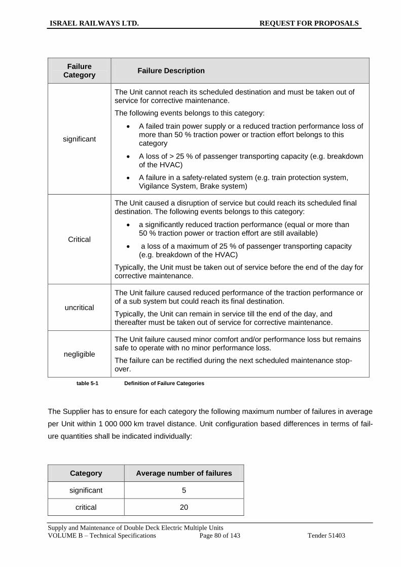
ISRAEL RAILWAYS LTD. REQUEST FOR PROPOSALS
Supply and Maintenance of Double Deck Electric Multiple Units
VOLUME B – Technical Specifications Page 80 of 143 Tender 51403
Failure Category
Failure Description
significant
The Unit cannot reach its scheduled destination and must be taken out of service for corrective maintenance.
The following events belongs to this category:
A failed train power supply or a reduced traction performance loss of more than 50 % traction power or traction effort belongs to this category
A loss of > 25 % of passenger transporting capacity (e.g. breakdown of the HVAC)
A failure in a safety-related system (e.g. train protection system, Vigilance System, Brake system)
Critical
The Unit caused a disruption of service but could reach its scheduled final destination. The following events belongs to this category:
a significantly reduced traction performance (equal or more than 50 % traction power or traction effort are still available)
a loss of a maximum of 25 % of passenger transporting capacity (e.g. breakdown of the HVAC)
Typically, the Unit must be taken out of service before the end of the day for corrective maintenance.
uncritical
The Unit failure caused reduced performance of the traction performance or of a sub system but could reach its final destination.
Typically, the Unit can remain in service till the end of the day, and thereafter must be taken out of service for corrective maintenance.
negligible
The Unit failure caused minor comfort and/or performance loss but remains safe to operate with no minor performance loss.
The failure can be rectified during the next scheduled maintenance stop-over.
table 5-1 Definition of Failure Categories
The Supplier has to ensure for each category the following maximum number of failures in average
per Unit within 1 000 000 km travel distance. Unit configuration based differences in terms of fail-
ure quantities shall be indicated individually:
Category Average number of failures
significant 5
critical 20

ISRAEL RAILWAYS LTD. REQUEST FOR PROPOSALS
Supply and Maintenance of Double Deck Electric Multiple Units
VOLUME B – Technical Specifications Page 81 of 143 Tender 51403
Category Average number of failures
uncritical 30
table 5-2 Reliability Requirements related to the
Unit
The Bidder shall indicate the Negligible failure category average number of failure which will be
achievable by the Unit design.
For the following major systems of the Unit in different configuration the Bidder shall stipulate the
MDBF (Mean Distance Between Failures) values achievable in its offer considering all failure cate-
gories with exception of the negligible failures.
No. Principal main product assemblies MDBF/ km
1 Running gear: Consisting of bogies and suspension, wheelsets / wheels, bearings, axles, dampers, etc.
……..
2
Traction system, incl. the corresponding high voltage system: Consisting of pantographs, MCB, switches, overvoltage protection devices, sensors, transformer, traction converter, traction motor, gearbox, drive system and corresponding cooling systems, traction control
……..
3
Train control and monitoring system (TCMS): Consisting of Unit and train control incl. train safety and monitoring systems as well as diagnostic systems, and train radio equipment.
……..
4 Passenger information system ……..
5 HVAC (air-conditioning and ventilation) ……..
6 Brake system: Consisting of the brake control system, air supply and distribution, pneumatic / hydraulic equipment incl. piping
……..
7 Train supply system: Consisting of converter for train supply, train power line, external connections and switches
……..
8 Battery system, incl. battery charger and battery ……..
9 External door system ……..
10 Internal door system ……..
11 Toilet system ……..
12 Automatic coupling system ……..
table 5-3 MDBF values to be defined by the Supplier

ISRAEL RAILWAYS LTD. REQUEST FOR PROPOSALS
Supply and Maintenance of Double Deck Electric Multiple Units
VOLUME B – Technical Specifications Page 82 of 143 Tender 51403
5.5 Availability Requirements
From the view point of the vehicle operator, the operating availability of the Unit is relevant as a
key category. This availability calculation of the offered Units must be provided in the offer and
shall be verified in commercial operation as described above.
5.5.1 Availability
The availability definition and monitoring shall be distinguish between a delivered batch of Units
where ISR will be responsible to perform the maintenance and a batch delivered where a Supplier
has taken over the full maintenance responsibility.
The Availability definition as outlined below shall be applied to the delivery batch where ISR is in
charge of maintenance.
The Availability effective for Supplier Maintained Fleet is described in the Maintenance chapter,
Maintenance regime, in Annex 10.
Availability = Total operation time period - Total time of non-availability
Total operation time period
Total operation time period: Quantity of units which are part of the considered fleet or sub-fleet
multiplied with the daily operation and the considered operation days
within the considered calendar time period.
Total time of non-availability: Sum of non-available time of all units within the considered fleet or
sub-fleet.
Units of the considered fleet at which the overhaul work is executed shall be deducted from the
calculation during this period. Nevertheless the allocated down time due to overhaul shall be sub-
mitted .
In its offer the Bidder shall provide the calculated availability considering the indicative defined op-
erational data as listed in table 5-4. This calculation must detail the time allocated for all relevant
work and activities of preventive maintenance as stipulated in the submitted maintenance plans,
the estimated values for corrective maintenance and any other foreseen activity.
It is hereby clarified that the values of the different parameters in the operational data specified
below shall not be construed as a representation and/or an undertaking by ISR with respect to the
effective values that will be in force from time to time. The operating hours and/or the number of
annual operation days may be modified by ISR in accordance with its operational needs and con-
straints. Furthermore, the annual number of kilometres travelled by any or all Units and at the av-
erage may exceed the number of kilometres specified below.

ISRAEL RAILWAYS LTD. REQUEST FOR PROPOSALS
Supply and Maintenance of Double Deck Electric Multiple Units
VOLUME B – Technical Specifications Page 83 of 143 Tender 51403
Operational Data
Operating lifetime 30 years
Annual operation days 270 days
Average daily operation time 18 hours
Unit maintenance overhaul intervals To be specified by the Supplier
Average annual mileage (estimated) 175 000 km
table 5-4 Operational data
As result the assured values of the monthly availability, considering 30 calendar days and yearly
availability at 365 calendar days as guiding average value over the whole operating lifetime shall
be submitted separately by following categories:
- Short Units;
- Long Units.
During the whole operating lifetime of the units the following availability thresholds shall be met as
a minimum:
Calendar Time Period Threshold value
Monthly Availability AM 30 days >= 96.5 %
Yearly Availability AY 365 days > 96.5 %
table 5-5 Availability Thresholds
Remark:
The first valid monthly and yearly value shall be calculated when the considered time interval
reached the specific Calendar Time Period.
The verification of the offered availability values shall be carried out per delivery batch by a joint
team together with the Supplier and led by ISR during the warranty period as soon as the Units
have successfully finished their fault free running in revenue service. The determined actual avail-
ability values shall not be smaller than the offered values during the verification period.
5.5.2 Maintainability Requirements
The definition of Maintainability is according to EN 50126.
The maintainability includes the MTTR -> Mean Time To Repair and refers to the average time
required for maintenance due to relevant faults of a system on the Unit. MTTR refers to repairable
units only as a part of system availability.
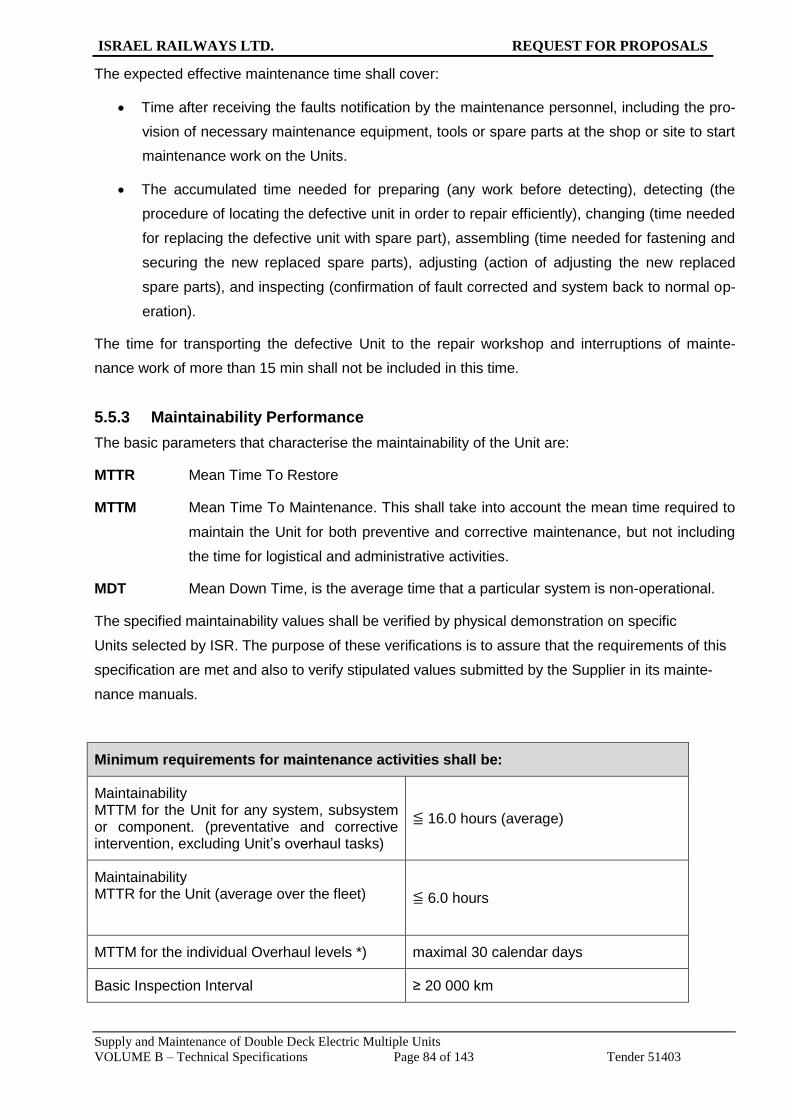
ISRAEL RAILWAYS LTD. REQUEST FOR PROPOSALS
Supply and Maintenance of Double Deck Electric Multiple Units
VOLUME B – Technical Specifications Page 84 of 143 Tender 51403
The expected effective maintenance time shall cover:
Time after receiving the faults notification by the maintenance personnel, including the pro-
vision of necessary maintenance equipment, tools or spare parts at the shop or site to start
maintenance work on the Units.
The accumulated time needed for preparing (any work before detecting), detecting (the
procedure of locating the defective unit in order to repair efficiently), changing (time needed
for replacing the defective unit with spare part), assembling (time needed for fastening and
securing the new replaced spare parts), adjusting (action of adjusting the new replaced
spare parts), and inspecting (confirmation of fault corrected and system back to normal op-
eration).
The time for transporting the defective Unit to the repair workshop and interruptions of mainte-
nance work of more than 15 min shall not be included in this time.
5.5.3 Maintainability Performance
The basic parameters that characterise the maintainability of the Unit are:
MTTR Mean Time To Restore
MTTM Mean Time To Maintenance. This shall take into account the mean time required to
maintain the Unit for both preventive and corrective maintenance, but not including
the time for logistical and administrative activities.
MDT Mean Down Time, is the average time that a particular system is non-operational.
The specified maintainability values shall be verified by physical demonstration on specific
Units selected by ISR. The purpose of these verifications is to assure that the requirements of this
specification are met and also to verify stipulated values submitted by the Supplier in its mainte-
nance manuals.
Minimum requirements for maintenance activities shall be:
Maintainability MTTM for the Unit for any system, subsystem or component. (preventative and corrective intervention, excluding Unit’s overhaul tasks)
≦ 16.0 hours (average)
Maintainability MTTR for the Unit (average over the fleet)
≦ 6.0 hours
MTTM for the individual Overhaul levels *) maximal 30 calendar days
Basic Inspection Interval ≥ 20 000 km

ISRAEL RAILWAYS LTD. REQUEST FOR PROPOSALS
Supply and Maintenance of Double Deck Electric Multiple Units
VOLUME B – Technical Specifications Page 85 of 143 Tender 51403
Minimum requirements for maintenance activities shall be:
Accumulated running distance
All systems and components of high voltage, electronics and traction chain, including wheels and wheelsets, shall not have any overhaul intervention or replacement within this period (Re-profiling of wheels excluded).
minimum 750 000 km
table 5-6 Maintainability Requirements
*) The MTTM overhaul values for Units in different configurations shall be submitted considering
potential different levels of overhaul over the 30 year rolling stock assumed operating period.
The Bidder shall offer the values as described in Table 5-6 above with its offer.
5.6 Safety
The technical equipment of the Unit must be in compliance with the safety requirements in railway
operation as defined by EN, TSI (incl. TSI-SRT, Safety in Railway Tunnels) and ISR standards, as
well as National Israel standards where applicable. Failures which might occur in the systems of
the Units must always lead to a safe state of the Unit and never to a safety risk in operation. The
EN 50126 describes the characteristic of safety and shall be applied.
The Supplier shall guarantee a safe operation of the Units, and must provide an assessment of
possible critical failures. The objectives of the required safe design shall ensure that no failure or
deficiency will result in a catastrophic or critical accident.
To this purpose, it is necessary that the Supplier shall submit ‘Safety Targets’ by referring to at-
tachment D.3 of EN 50126, assuming that the Unit would be operated with 1000 passengers. The
submitted ‘Safety Analysis’, if approved by ISR, serves as the acceptance standard for the quanti-
fied risk evaluation. In the “Safety Analysis”, the equivalent fatality per person and per year shall be
adopted for working staff and non-railway personnel as a counting unit.
Severity level Consequence to persons or environment
Consequence to service
Catastrophic Fatalities and /or multiple severe injuries and/or major damage to the environment
Stop of service of the whole fleet of Units
Critical Single fatality and/or severe injury and/or significant damage to the environment
Immediate safety assess-ment of the complete fleet and potential stop of service of all Units or specific Units
Marginal Minor injury and/or significant threat to the environment
Immediate halt of all activi-ties of the corresponding Unit

ISRAEL RAILWAYS LTD. REQUEST FOR PROPOSALS
Supply and Maintenance of Double Deck Electric Multiple Units
VOLUME B – Technical Specifications Page 86 of 143 Tender 51403
Severity level Consequence to persons or environment
Consequence to service
Minor or insignificant Possible minor injury
Immediate assessment and elaboration of proposals to avoid such injuries in the future
table 5-7 Definition of severity levels
The Safety Analysis and its design verification covering the offered Unit shall be provided prior to
the final design review. This shall be demonstrated by a satisfactory ‘Hazard Analysis and Failure
Mode’, a ‘Risk Matrix and Effects Analysis’ (FMEA) as a systematic technique for failure analysis
used in the early design phase.
A hazard control program shall be a part of the design of operational procedures and shall be pro-
vided in the course of the Unit design.
The severity levels and consequences described in the table above shall be the framework of the
assessment.
5.7 LCC Analysis
In its offer the Bidder shall provide separate LCC-calculations for the Short Unit as well as the Long
Unit based on the following model, considering the operational boundaries as described in
Table 5-4, in paragraph 5.5.1 above, covering the following major cost items:
Total cost of Unit subcomponents to be replaced during the lifecycle period.
Total maintenance costs:
Total costs for preventive and corrective maintenance over a 30 years period shall be cal-
culated based on the submitted maintenance schedules and manuals, including the labour
and material costs for each inspection and overhaul interval, considering an annual 3% in-
flation rate as well as the disposal and recycling costs of used materials. An average value
of 1 200 ILS/day shall be taken for all labour costs, and the material costs shall be taken
from the price list for strategic spare parts as to be submitted by the Bidder, if available. It
shall be assumed that all scheduled and unscheduled tasks would be conducted in ISR
workshops with ISR personnel based on the manufacturer specifications.
Total energy costs shall be calculated considering :
- the operational mass and operational payload as defined in EN 15663;
- ambient temperature of 30 °C and 50 % humidity;
- nominal catenary voltage.
The needed auxiliary power for the Unit shall be included and highlighted separately.
Energy costs of 0.60 ILS/kWh are to be used.

ISRAEL RAILWAYS LTD. REQUEST FOR PROPOSALS
Supply and Maintenance of Double Deck Electric Multiple Units
VOLUME B – Technical Specifications Page 87 of 143 Tender 51403
Daily load cycle
(in %) (assumption)
Power P at the wheels and de-
fined train speed Comment
10 P = 100%, 160 km/h Full traction power
18 P = 75%, 120 km/h Partial traction power
22 P = 30%, 80 km/h Partial traction power
50 P = 0%, 0 km/h Idling
table 5-8 Load cycle assumption for LCC calculation
The calculated energy consumption figures shall be verified by means of a suitable type test which
simulates each of the above mentioned operation modes (4 modes for short and long unit, each).

ISRAEL RAILWAYS LTD. REQUEST FOR PROPOSALS
Supply and Maintenance of Double Deck Electric Multiple Units
VOLUME B – Technical Specifications Page 88 of 143 Tender 51403
6 Maintenance
6.1 General Issues
The requirements referring to the Unit must not induce any exceptional maintenance effort (e.g.
premature exchange or replacement).
The following requirements shall be fulfilled:
Basic interval between inspections: ≥ 20,000 km or integral multiple;
Interval between maintenance interventions ≥ 100,000 km or an integral multiple of the in-
terval between inspections;
Overhaul of the running gear ≥ 1,200,000 km or an integral multiple of the interval between
maintenance interventions;
Overhaul of the vehicle ≥ 2,000,000 km or an integral multiple of the interval between large
overhauls of the running gear
Differences in regard to Short Unit and Long Unit shall be indicated. The Bidder shall provide the
related maximum down times which are required for the different maintenance actions as listed
before together with the considered boundaries.
6.2 Modular Design
In the design, a modular principle for all assemblies (mechanical, electrical, compressed air circuit
etc.) shall be implemented. The attachment of these modules and their electric or air respectively
cooling agent connections (protected, safe multi-pole electric connectors, qui connectors for cool-
ing agents and compressed air) shall be designed such that replacement of all modules can be
executed as fast as possible. Every module shall be provided with appropriate lifting points.
The devices located within the modules shall be easily accessible and replaceable.
Traps, covers and flaps (if possible with identical dimensions), which cover the parts or devices to
be inspected, shall be fitted with simple and safe quick-release fasteners. Access to parts which
are energised above 1000 V shall be hampered by special locking mechanisms. Parts which are
particularly difficult to access or to maintain shall be designed in a way that warrants a lifetime of
30 years without requiring major maintenance due to corrosion or ageing. This applies especially
for carbody, bogies, running gear and pipework / wiring/ cabling.
6.3 On-Board Tools and Accessories
The on-board tool and accessories kit shall be suggested by the Supplier and agreed with ISR. For
its placement, an easily accessible and well illuminated location shall be provided. Tools shall be
stored in a cabinet well-arranged and safely. By an exact predetermination of the arrangement of

ISRAEL RAILWAYS LTD. REQUEST FOR PROPOSALS
Supply and Maintenance of Double Deck Electric Multiple Units
VOLUME B – Technical Specifications Page 89 of 143 Tender 51403
the tools and accessories in the cabinet, it shall be warranted that the absence of parts is recog-
nised at once.

ISRAEL RAILWAYS LTD. REQUEST FOR PROPOSALS
Supply and Maintenance of Double Deck Electric Multiple Units
VOLUME B – Technical Specifications Page 90 of 143 Tender 51403
7 Fire Protection
7.1 General Issues
The Unit shall meet the dedicated requirements defined by standards and specifications allowing
safe passenger operation at the specific characteristics and alignment of the ISR network espe-
cially in regard to tunnel length up to 20 km.
The following regulations shall be complied with:
TSI SRT Technical Specification of Interoperability relating to "Safety in railway tunnels",
(Category B rolling stocks)
TSI LOC PAS
EN 45545 part 1 to 7 "Fire protection in rail vehicles“
UIC leaflets 564-2 and 642
In case of contradictions within the aforementioned rules and standards, the hierarchy as defined
in paragraph 1.4 is to be applied.
The Bidder shall provide the general fire safety concept of the offered Unit design. This description
shall also describe resulting consequent actions to the operation of the propulsion and venting sys-
tem, dealing with fire-barriers and assumed evacuation measures.
The design consideration in order to prevent, detect and extinguish potential fire events and smoke
spreading within the passenger compartments and machine cabinets shall be described in the of-
fer.
Supplier shall support ISR with additional safety assessments, if so required in the future, with re-
spect to specific tunnel design issues relevant to the interface to the rolling stock design.
Additionally to the obligatory fire detection system a fire distinguishing system shall be provided in
order to minimize the subsequent risk to the passenger and train staff and to the rolling stock
equipment.
The fire distinguishing system shall be designed to be operated automatically..

ISRAEL RAILWAYS LTD. REQUEST FOR PROPOSALS
Supply and Maintenance of Double Deck Electric Multiple Units
VOLUME B – Technical Specifications Page 91 of 143 Tender 51403
8 Environment Protection and Ecology
The design of the Unit shall comply with the legal prescriptions concerning environment protection
for its operation, maintenance and disposal/recycling.
In generally, the UIC “Environmental Guideline for the Procurement of new Rolling Stock-July
2003” shall be fulfilled.
All components and subsystems in the vehicle containing polluting liquids must dispose of respec-
tive retention trays.
The used materials, their components and compounds shall be chosen with regard to the useful
lifetime, subsequent otherwise use or recycling and finally to the environmentally compatible dis-
posal.
The classification of the materials shall be as follows:
Type and mass of materials, that can be recycled
Mass of the electric scrap
Mass of the electronic scrap
Mass of combustible materials
Mass of the materials to deposit
The masses of the material classes as classified before shall be listed in the technical proposal
considering the Short Unit as well as the Long Unit.
The following materials shall be used:
Materials with low or no toxic content (e.g. isolation without asbestos, PVC)
Durable products / materials
Recyclable respectively maintainable materials with a diversity as small as possible
Noise emissions are also a part of the considerations regarding environmental protection.

ISRAEL RAILWAYS LTD. REQUEST FOR PROPOSALS
Supply and Maintenance of Double Deck Electric Multiple Units
VOLUME B – Technical Specifications Page 92 of 143 Tender 51403
9 Design, Development and Technical Documentation
9.1 General
This chapter outlines the logistic support requirement, which will be provided as part of the con-
tract. Different Unit configuration design in providing four and six vehicle unit shall be considered:
Technical documentation
Training
Technical support
9.2 Project Control Plan
Not later than 30 days after NTP, the Supplier shall submit the project control plan for the realiza-
tion of the contract. The plan shall include, as a minimum, the following:
1. Contract performance and progress schedule, including a graphical timeline (bar chart or
schematic diagram). It shall show mandatory milestone dates and specified times of deliv-
ery of specified items.
2. Program for basic design development, subsystem selection, and system engineering and
testing requirements for the subsystems.
9.3 Progress reports during Production Phase
The Supplier shall submit to ISR monthly progress reports during the production phase, the as-
sembly phase and during the testing and supply periods.
9.4 Technical Documentation
The documentation to be provided by the Supplier shall be at least but not limited following the
requirement and description outlined by TSI LOC PAS, Item 4.2.12 – Documentation for Operation
and Maintenance.
The Supplier shall develop a master plan and a schedule for the development and completion of all
the documents to be provided to ISR.
A full set of draft documents, including those provided to the Supplier by Subcontractors, shall be
submitted for ISR review no more than 6 months after NTP.
ISR approved "as-build" drawings shall be the requisite to commence the manufacture process of
train sets. Design documents shall be reviewed to become the status "as-build" for further activity.
The Supplier shall submit the documents “as-build” drawings in electronic format.
The language of the documentation shall be:
Drawings, test reports, certificates, etc. English

ISRAEL RAILWAYS LTD. REQUEST FOR PROPOSALS
Supply and Maintenance of Double Deck Electric Multiple Units
VOLUME B – Technical Specifications Page 93 of 143 Tender 51403
Manuals, operations instructions, etc. English
However, upon ISR’s request the Supplier shall provide a Hebrew language version of the docu-
mentation for no additional costs.
Software version shall be in English and in Hebrew
Three months before issuance of the Acceptance Certificate for a Unit under the Contract, the
Supplier shall submit the electronic documentation considering the Short and Long Unit configura-
tion in an approved format of IETM. The final version of the IETM shall be delivered after remedy of
the open items no later than one year after acceptance of the first Unit in different configuration.
ISR shall get free licenses for using and updating the IETM during the whole lifetime of the Unit.
9.5 Configuration Control
9.5.1 General
The Supplier shall provide a Configuration Management Plan to outline the requirements as de-
scribed in sections 9.5.2, 9.5.3 and 9.5.4 which are also to be applied for the software in use.
9.5.2 Technical Documentation
The Supplier shall maintain technical documentation records, which allow:
(a) Identification of any part of any level of the system;
(b) Identification of the next assembly drawing number of any equipment
(c) Tracing the associated documents for each part such as:
- Specification control drawings
- Source control drawings
- Sub-Contractor, vendor or Supplier part number
9.5.3 Records
The Supplier's documentation shall be capable of identifying changes and of retaining the record of
superseded configuration requirements affecting items which have been formally accepted.
The configuration control system shall allow the clear identification of the "as-built" condition of
every individual vehicle, even when design changes have been introduced during series production
on part of the vehicles. This information shall be included in the vehicle log-book.
The Supplier shall employ a system of identifying numbers for specifications, drawings and associ-
ated documents which will ensure that parts, assemblies and installations are uniquely identifiable
with regard to form, fit and function.

ISRAEL RAILWAYS LTD. REQUEST FOR PROPOSALS
Supply and Maintenance of Double Deck Electric Multiple Units
VOLUME B – Technical Specifications Page 94 of 143 Tender 51403
9.5.4 Submittal of changed Documents
During the warranty period, the Supplier shall resubmit any changed drawing, report or document
in an appropriate and transparent format.
9.6 Development and Design Approval
The Supplier shall submit for ISR review in electronic and hardcopy format no later than six months
after NTP:
All assembly and major component drawings
Calculations
Electrical diagrams
Catalogue documents
Test reports.
The ISR review is to verify general conformity of the design with the specification and does not
relieve the Supplier of any responsibility.
All drawings and documents shall be presented in the English language.
However, upon ISR’s request the Supplier shall provide a Hebrew language version of all the draw-
ings and documents for no additional costs.
The ISR review is to verify general conformity of the design with the specification and does not
relieve the Supplier of any responsibility.
All information shall be submitted within the time specified enabling ISR to verify before manufac-
turing of the relevant parts will start, so that in case of non-conformity the Supplier can take steps
to remedy this situation.
All computer calculations shall be presented in such a way that the results can be checked by
means of none-programmed calculations, based on generally accepted methods.
Design approval can be in the form of design reviews, organized by the Supplier. The process
ends with the design approval by ISR and design freeze.
9.7 Documents with the Start Point of Manufacturing Inspection
9.7.1 General
The following documents shall be supplied concurrent with the start point of the manufacturing of
the Unit:

ISRAEL RAILWAYS LTD. REQUEST FOR PROPOSALS
Supply and Maintenance of Double Deck Electric Multiple Units
VOLUME B – Technical Specifications Page 95 of 143 Tender 51403
9.7.1.1 Mechanical Drawings
Detailed drawings of the carbody, bogie structure and all other components with its bills of material
shall be provided by means of electronic documents.
9.7.1.2 Calculations
Calculations related to the structure, assembling, mechanisms and electric components shall be
supplied by means of electronic documents.
9.7.1.3 Electrical system documents
Electrical system data as electronic files shall consist of:
Block diagram
Single line diagrams and functional/logical descriptive text explaining all the functions of the
control system and its components
Detailed circuit diagrams of the electrical system
Guide for fault-finding
Mechanical diagrams showing all electrical components layout on the Unit.
Component layout and internal wiring diagrams of all cubicles, panels, controllers, control
consoles and the like
Terminal diagram - interconnection wiring diagrams, showing the connections of all compo-
nents and devices complete with number of conductors and wire numbering
Unit wiring diagrams showing the internal wiring of shop-made mounting units, e.g., a cir-
cuit- breaker, a relay set or a regulator (no “Black Boxes” are permitted. No unit may be left
without information as to their purpose content and interior connection)
Conduit, cable layout drawings, drawn to scale
Cable list
Electric machines test certificate, load testing and measurements results, dial settings of
the potentiometers and the measurements in all test points
Full test data on the cubicles and electric modules
Recorder charts of test runs for all train functions
List of components giving detailed and complete information on technical data, manufac-
turer’s address and ordering reference and the purpose of the component in the equipment.
Program listing and software media of the control software
9.7.1.4 Data Sheets
Performance charts of the Unit and all its major components.
ISRAEL RAILWAYS LTD. REQUEST FOR PROPOSALS
Supply and Maintenance of Double Deck Electric Multiple Units
VOLUME B – Technical Specifications Page 96 of 143 Tender 51403
9.8 Documents to be Submitted Before Acceptance of the Unit
The Supplier shall provide a document delivery planning at least 3 months after NTP1.
The planning shall define the delivery date of the documents to be delivered by the Supplier. The
delivery date of the documents shall consider the ISR effort to perform the labour training to the
operation and maintenance related tasks.
9.8.1 General Specification of the Unit type
The provision made by TSI LOC PAS item 4.8 and the provision made to register authorized types
of railway vehicle in accordance with Directive 2011/665/EU to define the main technical character-
istics of the Unit types in different configurations shall be used to provide the Unit type registering
document accordantly for further MOT action to register the Unit into the National Israeli Rolling
stock Register.
9.8.2 Manuals
Operating and maintenance manuals and parts catalogues for the Unit and all its mechanical and
electrical equipment, shall be submitted in electronic and in hardcopy format. The operating and
maintenance manuals shall be presented in English.
However, upon ISR’s request the Supplier shall provide a Hebrew language version of operation
and maintenance manuals for no additional costs.
9.8.3 Documentation and manuals concept
The documentation mentioned above shall be comprehensive to the extent that in the event of a
failure of a working part of any manufactured component, maintenance personnel will be able to
refer the parts data books to obtain the model number of the component and order the required
part without being compelled to dismantle the component.
These books will be utilized in training inexperienced personnel for operation and maintenance and
shall be based on the following operation, maintenance and illustrated spare parts catalogue
manuals specification as described in the following paragraphs.
9.8.4 Operating Instructions - Driver’s Manual
The documents to be provided by the Supplier shall follow at least, but not limited, the below re-
quirements described by TSI LOC PAS:
Item 4.2.12.4 – Operating Documentation
Item 4.2.12.5 – Lifting Diagram and Instruction
Item 4.2.12.6 – Rescue related description
In detail, it shall at least outline the following paragraphs:
Pre-operation check-out

ISRAEL RAILWAYS LTD. REQUEST FOR PROPOSALS
Supply and Maintenance of Double Deck Electric Multiple Units
VOLUME B – Technical Specifications Page 97 of 143 Tender 51403
Start-Up procedure
Operation procedure (operation limitations should be stated clearly and in bold letters)
General data on the Unit and description of the structure, drives and auxiliary systems
Detailed description of all the control in the cabs and other control stations - their functions
limitations and interlocking
Shut-down procedure
Emergency and rescue procedures.
Troubleshooting
9.8.5 Maintenance Documentation and Procedures
The TSI LOC PAS, Item 4.2.12.3 describes in detail the requirement of documents to be provided
to the operator by the Supplier in regard to maintenance activities intending to keep a functional
unit in, or to restore it to, a state in which it can perform its required function, ensuring continued
integrity of safety systems and compliance with applicable standards (definition as per standard EN
13306).
9.8.5.1 Maintenance Principle and Methods
In accordance to TSI LOC PAS Item 4.2.12.3.1 the Supplier shall provide at least but not limited:
Precedents, principles and methods used to design the maintenance of the unit
Utilization profile: Limits of the normal use of the unit (e.g. km/month, climatic limits, author-
ized types of loads etc.)
Relevant data used to design the maintenance and origin of these data (return of experi-
ence)
Tests, investigations and calculations carried out to design the maintenance.
9.8.5.2 Maintenance Strategy
In accordance to TSI LOC PAS Item 4.2.12.3.2 the Supplier shall provide the description how
maintenance shall be conducted. As outlined by TSI definition the maintenance activities include all
activities necessary such as inspections, monitoring, tests, measurements, replacements, adjust-
ments, repairs.
Maintenance activities shall be split into:
Preventive maintenance; scheduled and controlled,
Corrective maintenance
The tasks are to be described separately.
ISRAEL RAILWAYS LTD. REQUEST FOR PROPOSALS
Supply and Maintenance of Double Deck Electric Multiple Units
VOLUME B – Technical Specifications Page 98 of 143 Tender 51403
The General maintenance target requirement described by chapter 6 – Maintenance shall be con-
sidered as a min requirement.
9.8.5.3 Maintenance Tasks Description
As in detail described by TSI the maintenance document shall outline:
The component hierarchy and functional description
Schematic circuit diagrams, connection diagrams and wiring diagrams
Parts list containing the technical descriptions of the spare parts and their references, in or-
der to allow identification and procurement of the correct spare parts, The list shall include
all parts specified for changing on condition, or which may require replacement following
electrical or mechanical malfunction, or which will foreseeable require replacement after
accidental damage
The limit values for components which shall not be exceeded in service shall be stated; the
possibility of specifying operational restrictions in degraded mode (limit value reached) is
permitted
The structured set of tasks that include the activities, procedures, means proposed by the
applicant to carry out the maintenance task
The description of the maintenance activities
Disassembly/assembly instructions drawings necessary for correct assembly/disassembly
of replaceable parts
Maintenance criteria
Checks and tests
Tools and materials required to undertake the task
Consumables required to undertake the task
Personal protective safety provision and equipment
The documentation shall contain the Suppliers own equipment and parts of the rolling stock system
and the delivery from the subsidiaries.
The Supplier shall provide equipment list and the main specification of them to be procured from
the open market in preparation to execute the light and heavy maintenance at the rolling stock at
the ISR facilities.
9.8.6 Illustrated Part Catalogue
The parts catalogue shall be detailed to an extent of part breakdown and indicate the numbering
system as outlined below.

ISRAEL RAILWAYS LTD. REQUEST FOR PROPOSALS
Supply and Maintenance of Double Deck Electric Multiple Units
VOLUME B – Technical Specifications Page 99 of 143 Tender 51403
9.8.6.1 Parts Breakdown
Illustrated parts breakdown, including any of the subcontractor’s items with a set of section draw-
ings or axonometric/”blow-up” drawings and a list for each one of the drawings including the follow-
ing data elements:
Item number on the drawing
Item’s name
Subcontractor’s part number
Subcontractor name
Quantity per assembly
9.8.6.2 Part Numbers Index
Index of all part numbers appearing in the catalogue in P/N sequence having the following data
elements:
Part number
Drawing number
Drawing index number
The parts breakdown will also include drawings of the subcontractor’s items.
9.8.7 Document delivery format
The documents shall be delivered in electronic format, where the format shall be as follow:
Operator’s and Maintenance Manuals:
a. Source files in Microsoft Windows XP up to Microsoft Office 2007
b. PDF files (unlocked and data-copy-enabled)
c. Source templates approved by ISR, and provided to ISR if required. It is advised to
approve a general template (appearance, styles, fonts etc.) before the documenta-
tion process
Images format:
a. Images will be linked inside the WORD file and stored in a Graphics directory.
b. Vector files in PDF, CorelDraw, Adobe Illustrator etc.
c. 300 dpi GIF files, to be linked inside the WORD files.
d. Font for balloons and numbers is ARIEL 12
Printing preferences:
ISRAEL RAILWAYS LTD. REQUEST FOR PROPOSALS
Supply and Maintenance of Double Deck Electric Multiple Units
VOLUME B – Technical Specifications Page 100 of 143 Tender 51403
A4 or A5 page sizes, mirror printing, different even and odd headers.
Schemes:
Pneumatic, electrical, fuel and oil schemes and circuits will be provided in color and with
vector source files.
9.9 Interactive Electronic Technical Manual – IETM
Concurrent with the final acceptance of the first Unit, the Supplier shall provide the technical
documentation as an interactive electronic technical manual (IETM), namely as a high-quality da-
tabase product. This IETM will allow for multiple methods of accessing the data including full-text
and fielded searching, visual access and table of contents (TOC) access, as well as for interactive
cross-reference within each publication, and between different but related publications (e.g. cross-
references between Maintenance Manual and Parts Catalogue). The IETM user interface shall be
in English.
However, upon ISR’s request the Supplier shall provide a Hebrew language version of IETM user
interface for no additional costs.
The Supplier shall make proposals regarding the type of system to be implemented.
The IETM will support the following features (non-comprehensive list):
End-user access control
Annotations and bookmarks (annotations will support Hebrew)
Easy navigation between documents titles and sub-titles
Combined Boolean full-text and fielded searches
Nested querying - up to 4 nesting search levels
Compound documents viewer (text, tables, raster/vector images, audio, video, etc.)
Multi-target hyperlinks
External executable links
Exporting images in their native format; exporting text
Temporary Revisions and Updates
9.10 Lubrication Charts
The Supplier shall prepare framed plastic-coated lubrication charts for all systems, showing all
points to be lubricated, type of lubricant to be used at each location and recommended frequency
of lubrication.

ISRAEL RAILWAYS LTD. REQUEST FOR PROPOSALS
Supply and Maintenance of Double Deck Electric Multiple Units
VOLUME B – Technical Specifications Page 101 of 143 Tender 51403
In order to enable usage of lubricants available in the Israeli market, the Supplier shall provide,
three months after signature of the contract, a list of recommended lubricants for approval by the
Israel Railways and only the approved lubricants will be used during the construction and assembly
of the train and will appear on the lubrication charts.

ISRAEL RAILWAYS LTD. REQUEST FOR PROPOSALS
Supply and Maintenance of Double Deck Electric Multiple Units
VOLUME B – Technical Specifications Page 102 of 143 Tender 51403
10 Operation and Maintenance Training
10.1 General
Supplier shall develop and provide a training program supported by appropriate tools and training
material state-of-the-art like 3-D models, cut views, animations, videos e.g. for knowledge transfer
that accurately and completely reflects the requirements of the manuals, and be structured and
implemented so that the ISR operator and maintainer have access to all necessary resources to
properly and successfully operate, maintain and administer the vehicles as required to keep the
fleet operable on a high reliability level.
Supplier’s first step maintenance staff training shall be provided to qualify ISR staff being capable
to identify the rolling stock critical performance condition and availability relevant issues at the
Units which are under the supplier’s maintenance responsibility.
Furthermore, ISR staff shall be qualified by sufficient training to perform the daily service relevant
checks and tests on the Unit’s readiness for service operation at ISR’s operational overnight sta-
bling areas.
Upon ISR's request, Supplier shall provide the full maintenance training program and exercise the
training to ISR staff.
Supplier shall provide dedicated training courses in the Manufacturer’s facilities for driver instruc-
tors.
The maintenance instructors shall be trained in ISR training facility.
The courses shall cover operational and maintenance aspects of the system. Training shall be
conducted by the Supplier’s instructors, combining theoretical lessons with practical “hands-on”
lessons.
Training of personnel shall be provided for a minimum of three types of ISR personnel: drivers,
electricians and technicians.
Training of personnel by the Supplier shall be scheduled to take place at least 2 months before the
first system is received by ISR, in order to allow the ISR Training Department to prepare and train
its labour.
Optionally the Supplier shall provide a program to training the ISR drivers on site during the de-
fined operation implementation period.
The Supplier shall provide 3D cut views and 3D models in a format that will allows ISR to use and
develop further animations and products that are based on 3D model of the system.
The 3D model shall be provided in “.xt” “Step” or other solid based format. These types of files al-
low the Supplier to provide only a surfaces model, without giving the engineering knowledge of the

ISRAEL RAILWAYS LTD. REQUEST FOR PROPOSALS
Supply and Maintenance of Double Deck Electric Multiple Units
VOLUME B – Technical Specifications Page 103 of 143 Tender 51403
design and the manufacturing. ISR can help and provide further advice and aid in order for the
Supplier to fulfil this requirement.
The Supplier shall provide images folder that will cover all the systems and specially parts and as-
semblies (such as racks and circuit breakers) that are located within cabinets or enclosed area that
denies the possibility to take proper pictures once the equipment is installed. The image picture
folder shall cover all the maintenance tasks and operational task. Images will be given in open
source file format for further editing.
10.2 Class Room Training
Class room training shall consist of basic theory of the Unit systems and their operation in normal,
emergency and rescue operation condition.
10.3 On-the-Job Training
On-the-job training which shall include:
Equipment familiarization
Operation of the Unit types in different configurations for at least 2-5 operating hours for
each operator instructor, but at least to an extent where the operator instructor will be able
to operate the Unit safely
This training shall be provided to four driving instructors, which will then instruct the other operators
of the ISR. All training aids which will be used during the training will be left for the ISR’s use.
The on-the-job-training of the instructors shall be executed before the final acceptance test com-
pletion and the handing over of the first Unit in each configuration.
10.4 Maintenance Instruction
The Supplier shall develop a Maintenance training plan and the training document to an extent
allowing to perform the preventative and corrective tasks as part of the inspection and overhaul on
the rolling stock and with respect to the fact that ISR will implement a portion of Units into its own
maintenance system later on.
Upon ISR's written demand, the training of ISR's maintenance personnel shall be conducted by
Supplier and shall be instructed to two separate groups:
Mechanical systems technicians
Electrical systems technicians
10.4.1 Class Room Training
Class room instruction training shall contain the following:
System theory

ISRAEL RAILWAYS LTD. REQUEST FOR PROPOSALS
Supply and Maintenance of Double Deck Electric Multiple Units
VOLUME B – Technical Specifications Page 104 of 143 Tender 51403
Maintenance manuals, drawings and schematics organization and interpretation.
Equipment familiarization
Maintenance tasks performance which will include:
o Periodic inspections
o Corrective task and Trouble shooting
o Replacement and adjustment work (heavy and light maintenance)
10.4.2 On-the Job Training
On the job training and practical hands on.
10.4.3 Duration and Location for Training
The Supplier shall recommend the duration and location of the training sessions. The Supplier
shall be responsible to certify the knowledge transfer level to the extent which is required to per-
form the work in a safe manner.

ISRAEL RAILWAYS LTD. REQUEST FOR PROPOSALS
Supply and Maintenance of Double Deck Electric Multiple Units
VOLUME B – Technical Specifications Page 105 of 143 Tender 51403
11 Technical Support
The Supplier shall provide ISR with technical support as follows:
An electrical engineer, a mechanical engineer and a software engineer ("Technical Support Team")
shall be present in Israel for a period of 12 months, commencing the service from the final accep-
tance date of the first Unit in any configuration.
The members of the Technical Support Team shall be experts with hands on familiarity with the
Unit design, preferably, members of the Units design or development team.
The Technical Support Team shall perform as follows:
It shall coach and instruct ISR personnel in all aspects of carrying out Driver instructors’
service for the Unit, including troubleshooting activities. Such coaching and guidance shall
be in addition to the training services detailed in the Technical Specifications
It shall support ISR engineering teams and servicing staff in identifying potential faults and
malfunctions which are to be addressed to the Supplier’s warranty Teams activities
It is hereby clarified, that the activities of the Technical Support Team shall not in any way derogate
from the Suppliers obligations regarding the Warranty Team.
ISRAEL RAILWAYS LTD. REQUEST FOR PROPOSALS
Supply and Maintenance of Double Deck Electric Multiple Units
VOLUME B – Technical Specifications Page 106 of 143 Tender 51403
12 Warranty of the Supplier
Adequate and appropriate manufacturing of all assemblies shall guarantee the following warranty
periods according to the design:
3 years in general
6 years in respect to Endemic Failures
6 years for painting, labels
10 years for entire corrosion protection
Warranty for the specified design lifetime for the vehicle body of the Unit and the bogie
frames
Extension of the warranty period:
Extension by one year if one of the specified below RAM target values are violated by more
than 10 % for all Units of an specific configuration before expiration of the warranty the de-
livery batch of Units. Different target figures based on configuration will be considered.
RAM Criteria Target Deviation recorded entitling
ISR with extension
Reliability – Significant
failure
5 per 1.000.000
km >= 6 per 1.000.000 km
Reliability – Critical failure 20 per 1.000.000
km >= 22 per 1.000.000 km
Availability ≥ 96.5 % <= 86.85 %
table 12-1 RAM Targets
* The above values will be amended for monitoring purposes based on the offer of the bid.
Non-recurring extension by one year for the entire delivery if failures of the same subject
matter occur at least three times impairing the operational capability of the Units.
Non-recurring extension by one year for individual parts if failures of the same subject mat-
ter occur at least three times without significant impact on the operational capability of the
Units.
Non-recurring extension by one year for individual Units failing to meet one of the targets by
more than 50%, even though the targets are met on average by the entirety of all Units.
Non-recurring extension by the relevant warranty period for parts or for painting if rectifica-
tion of defects in the scope of the warranty or replacement were required.

ISRAEL RAILWAYS LTD. REQUEST FOR PROPOSALS
Supply and Maintenance of Double Deck Electric Multiple Units
VOLUME B – Technical Specifications Page 107 of 143 Tender 51403
13 Manufacturing Record Book MRB
For each vehicle of a Unit to be manufactured under this Contract, the Supplier shall prepare a
Manufacturing Record Book MRB which shall contain all relative documents and information in
regard to the specific vehicle. This logbook shall stay with the vehicle during the manufacturing
process and shall be continuously updated by the Supplier. It shall be properly structured and be in
durable form, so that it can be used by the ISR after delivery of the vehicle during its entire service
life. The vehicle MRB’s shall be formed to an Unit consist to be handed over after the Unit’s final
acceptance.
The MRB shall be structured as follows:
Table of contents
Summary sheet with Vehicle Data
Manufacturing History
Quality Records
Configuration List
Certificate of Completion of Factory Tests
Final Acceptance Certificate and Test Report
Fault Free Service Running Certificate

ISRAEL RAILWAYS LTD. REQUEST FOR PROPOSALS
Supply and Maintenance of Double Deck Electric Multiple Units
VOLUME B – Technical Specifications Page 108 of 143 Tender 51403
14 Acceptance Test
Acceptance tests comprise the type tests as well as routine testing including the final acceptance
test regarding the proper function and performance of the Units and its sub-components, individu-
ally in different configuration design.
Thus besides the quality assessment of materials, parts, components and assemblies the general
performance and safety of the 4 and 6 vehicle Unit consist design shall be demonstrated by tests.
According to the pertinent requirements of EN 50215 the Supplier shall provide a test plan which
shall also include the internal testing and commissioning program of the Supplier.
A first version of this test program shall be submitted during the design phase for reviewing and
approval by ISR. During the project execution this test plan can be modified in consultation with
ISR.
The type tests shall completely demonstrate the suitability for operation on the Trans European
Network (TEN) as well as with the special demands of ISR.
Thus the vehicle shall be tested as necessary for reaching an approval for operation within the
TEN and in regard the ISR infrastructure. Existing test results and homologations following the
European Directive 2008/57/EC will be taken into account based on the European “Cross Accep-
tance” procedure. For ISR’s review the related test documentation and homologation documents
are to be provided.
In this regard a Notified Body will be accepted when registered at the European Commission ERA
website: (http://ec.europa.eu/enterprise/newapproach/nando/index.cfm).
If the Supplier plans to use this option he shall create a recommendation table which lists the re-
quirement categories (A, B and C) with the following meaning:
Category “A”: Contains internationally accepted harmonized standards, like UIC leaflets or EN.
Once checked, they do not need re-checking.
Category “B”: Contains standards where there is uncertainty (checked in one country and might
be accepted in another). If so it will become a category “A”.
Category “C”: Contains undisputable, essential and necessary rules and requirements for a
country, which will always require checking before use i.e. requirements of the
relevant infrastructure.

ISRAEL RAILWAYS LTD. REQUEST FOR PROPOSALS
Supply and Maintenance of Double Deck Electric Multiple Units
VOLUME B – Technical Specifications Page 109 of 143 Tender 51403
15 Fault-free Running
Each Unit shall undergo fault-free running in revenue service for 5000 km to commence the war-
ranty period as specified in Section 16.5 to the Agreement.
16 Supplier's Maintained Fleet – General Provisions
16.1 General
The provisions set forth herein shall not derogate from any of the provisions set forth in the Agree-
ment including the Attachments therein. For the removal of doubt the order of precedence between
different documents is as specified in Section 2 to the Agreement.
ISR decided to outsource the maintenance of certain amount of Units to the Supplier.
Bidder is required to specify its proposed maintenance plan in the "Proposed Maintenance Ser-
vices".
The Units shall be maintained over the maintenance contract period following a scheduled preven-
tative and corrective maintenance concept where the key elements of ISR’s service operation
boundaries and the interface relevant information are outlined and described in the sections above.
The Units where the Supplier takes over the responsibility to perform the maintenance during the
contractual period shall be maintained at the Supplier’s Maintenance Depot.
Supplier shall perform the maintenance activities at the Supplier’s Maintenance Depot. Neverthe-
less, Supplier shall be prepared whenever required to perform certain minor repair activities as
described in the TSI LOC PAS at ISR’s stabling areas where the daily servicing checks are per-
formed by ISR staff.
16.2 Key Objectives of the Rolling stock maintenance under the Sup-plier’s provision
The Supplier’s work execution in providing the different maintenance levels shall consider the fol-
lowing key objectives of the rolling stock maintenance which has to be implemented to ensure a
safe working environment.
• Considering the principle of Safety first in all Supplier’s related maintenance action;
• Sustain a standard of rolling stock fleet safety through a qualified maintenance program by
regular inspection, preventative maintenance and component repair and replacements;
• Occupational health and safety in full compliance with the Israeli laws to be applied by or-
ganizing and execution of any maintenance tasks;
• Delivering of the rolling stock individual train set units on a daily basis to achieve or exceed
the availability and reliability target values established;

ISRAEL RAILWAYS LTD. REQUEST FOR PROPOSALS
Supply and Maintenance of Double Deck Electric Multiple Units
VOLUME B – Technical Specifications Page 110 of 143 Tender 51403
• Demonstrating quality of workmanship and maintenance procedure excellence complying
with latest industrial standards;
• Making sure the Supplier meets the passenger satisfaction standards;
• Implementing a continuous improvement management process to gain the cost efficient
maintenance and quality of the maintenance procedures.
The Bidder is requested to describe in its Proposed Maintenance Services the potential measures
on how to achieve the key objectives as described above.
16.3 Maintenance Quantities
The Supplier shall take over the full responsibility to provide the maintenance for the Units deliv-
ered to ISR as part of the delivery contract.
The quantity of Units to be maintained by the Supplier under the terms of maintenance contract
shall be as defined in the Supplier's Maintained Fleet, Section 19 to the Agreement :
• 18 Units in 6 - vehicle configuration;
• 6 Units in 4 – vehicle configuration.
The Supplier shall take into account a maintenance capacity flexibility considering a quantity ex-
tension up to 75% of the Units to be maintained without major depot layout design modifications in
the scope of work as described below.
16.4 Maintenance Concept
The maintenance concept to be developed and to be implemented by the Supplier shall aim to
keep the Units in operational, safe, reliable condition and to ensure passenger’s satisfaction which
shall be in compliance with the terms and descriptions defined in this Technical Specifications.
The Operational data in section 5.5.1, Table 5-4 to be used to establish the key boundaries of the
maintenance planning. Supplier shall adjust the planning in the event that ISR is required to update
the operational data over the Unit’s service period in order to meet the passenger transport vol-
umes demand.
The Supplier shall be responsible to verify and update the maintenance planning established
whenever design modifications are implemented to the Units over the maintenance service period.
The maintenance interval minimum target values specified in Section 6.1 above shall be consid-
ered while offering the Proposed Maintenance Services.
The Bidder shall describe any deviation or potential risk to implement such maintenance concept in
the Proposed Maintenance Services.

ISRAEL RAILWAYS LTD. REQUEST FOR PROPOSALS
Supply and Maintenance of Double Deck Electric Multiple Units
VOLUME B – Technical Specifications Page 111 of 143 Tender 51403
16.5 Scope of Maintenance Work
The Supplier shall provide the following maintenance activities over the defined maintenance con-
tract period including without limitation:
• Supplier shall be prepared to perform minor repair activities necessary to ensure safe op-
eration, as described in the TSI LOC PAS, at ISR’s stabling areas where daily servicing
checks are performed by ISR;
• Preventative light maintenance related inspections;
• Unscheduled corrective actions due to faults;
• Rolling stock wheel set re-profiling;
• Scheduled heavy maintenance overhaul tasks to the rolling stock and its components;
• Passenger comfort related component’s preventative and corrective works;
• Rolling stock refurbishment work;
• Daily service relevant tasks including for the removal of doubt the interior cleaning when-
ever the Units are in maintenance events at the Supplier’s managed Depot.
The regular daily servicing of Unit in regard to the cleaning and toilet servicing and check-ups will
be performed by ISR in their facilities according to the scope of work as described by TSI LOC
PAS.
For the removal of doubt, Unit's exterior car wash is excluded from the Supplier's obligations.
In addition to the Maintenance Services Supplier shall provide Excluded Repair Works as defined
in section 6 to the Maintenance Chapter to the Agreement for cases such as vandalism or acci-
dents which require corrective actions or rectifications of the Unit or its components.
16.6 Maintenance Contract Duration
The Maintenance Period, commencement, duration and options for extension are defined in the
Agreement in Section 19.2.
16.7 Management Task Preparation
The Bidder shall describe in its Proposed Maintenance Services a preliminary management and
labour mobilization planning.
This planning shall contain management organization structure and a job description of the key
work position within the organizational team structure.
The Proposed Maintenance Services shall describe the preliminary consideration to achieve the
local content of maintenance staff to be employed and the training and qualification measures re-
quired allowing continuously increasing the competence to perform work in a qualified manner at
the necessary level.

ISRAEL RAILWAYS LTD. REQUEST FOR PROPOSALS
Supply and Maintenance of Double Deck Electric Multiple Units
VOLUME B – Technical Specifications Page 112 of 143 Tender 51403
16.8 Maintenance Work Execution
16.8.1 Mobile Maintenance Service
The Supplier shall perform a mobile corrective maintenance service to the Units to rectify any fault
at ISR’s maintenance facilities, ISR’s servicing and stabling areas or wherever the Unit stranded
due to an technical fault at ISR’s network.
The Supplier shall prepare the organizational pre-requisites and to qualify maintenance staff ac-
cordingly to perform such kind of services and provide road-based supporting equipment allowing
to access the site in short time as reasonably possible.
The Bidder shall describe the planned consideration to meet the above requirement.
16.8.2 Stationary Work Execution at Maintenance Depot
The Supplier shall perform the entire scope of scheduled preventative and un-scheduled corrective
maintenance work in its own Maintenance Depot over the maintenance contract period.
16.9 Depot Development
Supplier is referred to Attachment F1 of the Agreement with respect to the responsibility allocation
between ISR and Supplier regarding to the design-built obligations and erection of the Depot.
The Depot design layout planning shall consider all functional requirements to execute the mainte-
nance work to the Units within the scope of maintenance services in the aspect of an proven work-
flow, including all functional required supporting work arrangements as track alignments, stabling
areas, warehouse and storages, cleaning sections, road access etc.
The design of the Depot shall follow the requirements as defined by European standards and good
workmanship considering specific Israeli requirement as well as to ensure the interface compliance
to the standards applied to design of the Units.
The offered depot design shall be verified by a safety concept document to proof the arrangements
fit for the environmental and technical based regulations and shall support safe work execution.
Bidder shall submit the concept Depot design layout, as part of the Proposed Maintenance Ser-
vices, in order to allow ISR to crosscheck the proposed depot design concept in terms of technical
reliance and economic efficiency.
The Bidder shall explain in detail the concept design consideration in regard to the functional Depot
areas.
The concept design layout planning shall identify the mandatory functional areas to be provided to
execute the Units different maintenance levels;
The overhaul specific depot facility requirements and milestones to be ready for services shall be
defined.

ISRAEL RAILWAYS LTD. REQUEST FOR PROPOSALS
Supply and Maintenance of Double Deck Electric Multiple Units
VOLUME B – Technical Specifications Page 113 of 143 Tender 51403
Bidder shall provide the preliminary calculations to elaborate the required maintenance pit quantity
and dimensional size, the number of tracks in the stabling area, the space and size estimation to
different maintenance component shop areas and to other work and social accommodations.
16.9.1 Depot Facility and Equipment Delivery
For the removal of doubt, Supplier’s responsibility shall be to deliver the full depot facility installa-
tion, maintenance equipment and tools required to carry out the inspection and maintenance work
at different maintenance levels as defined over the contract period.
The Bidder shall submit in the Proposed Maintenance Services a preliminary equipment and tool
list identifying the planned delivery and estimated installation milestones and the quantity to be
utilized in regard to the maintenance levels to be performed over the contract period.
The Bidder shall identify the critical equipment and tool items in regard to the delivery lead time
being available on site to perform the work.
16.9.2 Maintenance Workflow
The Bidder shall describe in its Proposed Maintenance Service concept the general maintenance
workflow and key maintenance work steps to be applied to the Units and sub-components in differ-
ent maintenance levels.
16.9.3 Depot Maintenance Arrangement and Capacity
The overall Maintenance Depot capacity shall be described by suitable calculation considering the
workflow arrangements proposed and the scope of work to be provided.
The Bidder shall provide in the Proposed Maintenance Service a simplified sequenced annual
maintenance scheduling to the fleet over the maintenance contract period considering:
• The quantity of Units in service and under the maintenance contract terms;
• The contract delivery schedule of Units supplied to ISR to service
• Planned annual average mileage of the Units in service;
• The maintenance plan to be applied to the Units;
The Bidder shall describe in the Proposed Maintenance Service the preliminary planning concept
to perform scheduled preventative maintenance tasks in ISR’s operation free daily time period.
The Unit's downtime to stay in preventative maintenance services at different service levels shall
be identified.
The preliminary workload planning information shall identify the below specified issues:
• Daily work regime of the labour involved in maintenance tasks;
• Direct labour quantity estimate required to execute such work program;

ISRAEL RAILWAYS LTD. REQUEST FOR PROPOSALS
Supply and Maintenance of Double Deck Electric Multiple Units
VOLUME B – Technical Specifications Page 114 of 143 Tender 51403
• Daily work load distribution to the labour;
The above workload planning information shall be in consistency with the information to be pro-
vided following the RAMS chapter instruction, in Section 5.7 – LCC – Analysis.
The Bidder shall submit in the Proposed Maintenance Service potential consideration in regards to
balancing the maintenance planning by optimizing the overall availability of the fleet and consider-
ing the daily and weekly workload distribution to the labour in its long term social responsibility.
16.10 Maintenance Material and Spare Parts Management
The Supplier’s responsibility shall be to provide the full maintenance material logistic to organize a
proper material planning procedure, timely delivery of the material to the site for its maintenance
purposes and safe warehouse and on site storages of the maintenance material considering the
Israeli environment condition and the regulation established in regard to dangerous material prop-
erties as well.
The Supplier’s responsibility in regard to maintenance material provision shall cover any material
items as classified to be:
• Standard material
• Consumable parts
• Replacement parts
• Assemblies and Subcomponents
The scope of work shall be provided to the entire fleet which will be in service operation up to the
time of its disposal and defined as the Supplier’s Maintained Fleet.
The material service shall be available from the first day of Unit’s service operation.
The Supplier shall offer the warehouse activities from its own managed Maintenance Depot.
The Bidder shall describe in the Proposed Maintenance Service the preliminary consideration in
regard to the maintenance material management logistic concept to define:
• Management organisation and key personal;
• Performance indicators measuring the efficiency and service level;
• Material planning and consumption recording procedures and instruments;
• Material supply chain approach and logistics;
• Warehouse design requirements and storages size estimates.
ISRAEL RAILWAYS LTD. REQUEST FOR PROPOSALS
Supply and Maintenance of Double Deck Electric Multiple Units
VOLUME B – Technical Specifications Page 115 of 143 Tender 51403
16.11 Maintenance Engineering and Reporting
16.11.1 Units Technical Documentation
The Supplier shall be responsible to remain the Unit's technical documentation up to date at any
time within the Agreement period.
The Supplier’s responsibility and obligation will be to submit any design update or design modifica-
tion relevant technical information to ISR considering the operational relevance as well.
The Bidder shall describe in its Proposed Maintenance Service the consideration in regard to im-
plementation of a design configuration management system.
16.11.2 Maintenance Management Information System (MMIS) and Maintenance Re-cords
Supplier shall be required to implement sufficient and structured MMIS as part of the maintenance
services allowing to collect all relevant maintenance information in regard to the tasks scheduling,
work content, maintenance material definition and property, material consumption estimates in
scheduled and corrective action, technical relevant design information and performance parameter
generated by maintenance tests to demonstrate Unit's readiness for service and finally the re-
cording of all maintenance activities performed to the specific Units to detail the labour’s work hour
consumption and the material consumed.
The comprehensive utilization of the MMIS shall be used to provide evidence that the maintenance
work is planned and being realized in an efficient and well-coordinated manner.
For the recordings to be generated the SAP software system shall be applied which is already im-
plemented at ISR’s maintenance organization. The records shall be made available and integrated
into ISR’s SAP systems for further retention.
The Bidder shall submit in its Proposed Maintenance Service the preliminary consideration to cus-
tomize the system configuration and a preliminary implementation approach.
16.11.3 Manufacturing Record Book
The Supplier's responsibility shall be to hold the manufacturing record books per Unit up to date in
order to record activities performed during the maintenance levels.
16.11.4 Fault Recording and Analysing
The Supplier’s engineering shall be responsible to implement a monitoring to the Unit's ability to
provide services and to the performance quality of the Unit systems taking further action by means
of appropriate analysis to identify and implement the design or maintenance based improvement
measures.
ISRAEL RAILWAYS LTD. REQUEST FOR PROPOSALS
Supply and Maintenance of Double Deck Electric Multiple Units
VOLUME B – Technical Specifications Page 116 of 143 Tender 51403
A FRACAS process (Failure Reporting Analysis and Corrective Action System) implementation
shall be used to report to ISR the investigation results of any faults reported and recording by train
set born system and to offer the measures to stabilize the design or processes.
Bidder shall offer in the Proposed Maintenance Service the preliminary consideration on how such
FRACAS process will be implemented.
16.12 Maintenance Planning and Corrective Action Advise
Supplier will be required to delegate sufficient qualified staff permanently to ISR’s operation and
maintenance control centre (OMCC) to support ISR’s management to coordinate and arrange:
• Unit's scheduled maintenance planning considering the service operation availability re-
quirements and the rolling stock circulation at the network;
• To provide engineering advises in real time to the train driver and / or train master operating
the Unit in service operation when fault records will be triggered for their actions
The Bidder is requested to describe in the Proposed Maintenance Service its considerations to
meet the tasks to support ISR staff in charge at the OMCC.
16.13 Maintenance Contract Performance Indicator
The maintenance contract execution performance will be measured to identify:
• The Reliability of the train sets to perform an uninterrupted service under best passenger
comfort condition
• Availability of train sets to be ready for operation service as scheduled by planning
Details to measure the performance indicators of the reliability and train set availability are estab-
lished and outlined in Annex 10 of the Maintenance Chapter.
The Bidder shall offer in the Proposed Maintenance Service the measures to be implemented to
meet the performance criteria over the Maintenance Period.

ISRAEL RAILWAYS LTD. REQUEST FOR PROPOSALS
Supply and Maintenance of Double Deck Electric Multiple Units
VOLUME B – Technical Specifications Page 117 of 143 Tender 51403
Appendixes
A Appendix A: Rail Types, Lines and Track Quality 118
A.1 Rail Types 118
A.2 General Criteria for Track Maintenance 118
A.3 Line and Track Parameters 119
A.4 Platforms Dimension and Data 120
B Appendix B: Specification of the Trip Time Calculation 123
B.1 Methodology 123
B.2 Horizontal plan 125
B.3 Vertical plan 126
B.4 Speed Profile: 128
C Appendix C: Running Dynamics 129
D Appendix D: Environmental Conditions 130
D.1 Climate and Environmental Conditions 130
D.2 Dust Concentrations in the Atmosphere 130
D.3 Sea Salt Concentrations in the Atmosphere 130
E Appendix E: Water Quality 131
F Appendix F: Air Conditioning Performance 132
F.1 HVAC Passenger Area 132
F.2 HVAC Driver’s Cab 138
G Appendix G: System Requirements 140
G.1 System layout 140
G.2 Distances between Passenger Stations 141
H Appendix H: Technical Requirements for Electronic Equipment 142
H.1 Ambient Temperature (supplementary to EN 50155, Paragraph 2.1.2) 142
H.2 Special Service Conditions (supplementary to EN 50155, Paragraph 2.2) 142
H.3 Testing 142

ISRAEL RAILWAYS LTD. REQUEST FOR PROPOSALS
Supply and Maintenance of Double Deck Electric Multiple Units
VOLUME B – Technical Specifications Page 118 of 143 Tender 51403
A Appendix A: Rail Types, Lines and Track Quality
A.1 Rail Types
The standard track gauge is 1,435 mm (nominal).
Rails on main lines are continuous welded except for the Beit – Shemesh – Jerusalem line in which
rails on curves with radius ≤ 170 m are connected with fish plates.
The following rail types are being used on the ISR network:
UIC 60, UIC 60 320Cr,UIC 54, U 50, S 49, U 33, BS 37
The rails are installed with an inclination of 1 in 40, 1 in 30 and 1 in 20.
Present types of sleepers are concrete monoblock, Franko-bagon and Wooden.
The minimal numbers of sleepers per km track is 1667.
A.2 General Criteria for Track Maintenance
Allowed tolerances:
Speed [km/h]
Rank
Twist1) [mm]
Surface1) [mm]
Gauge
[mm] Superelevation
[mm] Alignment1)
[mm]
1 120 - 160
B 4.5 8 -5 +8 5 6
C 9.0 15 -5 +20 8 9
D 12 20 -7 +30 12 12
2 80 - 120
B 5.0 10 -5 +10 7 7
C 11 18 -5 +25 11 11
D 14 22 -7 +31 15 15
3 40 - 80
B 7.0 13 -5 +15 10 9
C 14 22 -6 +30 15 14
D 16 24 -7 +32 21 19
4 0 - 40
B 10 18 -5 +20 13 12
C 17 28 -7 +30 20 18
D 18 30 -9(-11)+35 28 25
Table A-1: Tolerances for Track Maintenance
Remark:
Deviations below "B": Track accepted condition – measuring values are less or equal to “B”
Deviations from "B" up to "C": Alert limit– measuring values are greater than “B” and less than or equal to “C” - Regular planned maintenance operation

ISRAEL RAILWAYS LTD. REQUEST FOR PROPOSALS
Supply and Maintenance of Double Deck Electric Multiple Units
VOLUME B – Technical Specifications Page 119 of 143 Tender 51403
Deviations above "C": Intervention limit – measuring values are greater than “C” and less than or equal to “D” – Corrective maintenance required
Immediate action limit is given by measuring values greater than or equal to “D”. This would either
require reducing of the line speed or closing the track.
A.3 Line and Track Parameters
Parameter Unit Value
Standard track gauge [mm] 1,435
Gauge widening in tight curves
(in addition to standard 1,435
mm gauge dimension)
[mm]
≥300 0 250-299 5 200-249 10 <200 15
Horizontal Geometry
Curve radius on main lines [m] ≥190
Exceptional curves radii: 1 curve on Beit Shemesh-Jerusalem 56 curves Beit Shemesh-Jerusalem 1 curve on Rosh-Ha’ain l ine some curve on secondary line
[m]
141
200 – 150 191 120
Minimum S-curves radius with short tan-gent section (6m) and without tangent
[m]
150+150 190+190
Minimum radius in depot track [m] 80
Vertical Geometry
Maximum gradient along the length of existing lines (Beit Shemesh-Jerusalem line)
‰ 21
Maximum gradient along the length of future lines)
‰ 30
Minimum vertical curve radius on lines (concave /convex)
[m] 3,000
Cant (superelevation)
Maximum cant [mm] 150
Maximum cant deficiency for conventional trains
[mm] 130
Maximum cant in special cases(ballast -less track)
[mm] 150
Transition curves are always cubical pa-rabolas
Minimum transition curve length L - length h = cant V = speed Cant is introduced at a regular rate along such transitions curves
[m]
[mm] [km/h]
L = 0.006 * h * V
Distance between Centres of Tracks

ISRAEL RAILWAYS LTD. REQUEST FOR PROPOSALS
Supply and Maintenance of Double Deck Electric Multiple Units
VOLUME B – Technical Specifications Page 120 of 143 Tender 51403
Parameter Unit Value
v ≤ 160 km/h [m] > 4.5
160 km/h < v < 220 km/h [m] > 4.7
rail cant 1:30
equivalent conicity from wheel profile and track
0.12 - 0.24 at 3 mm lateral movement of the wheelset, max. single value 0.45
Table A-2: Main Line and Track Parameters
A.4 Platforms Dimension and Data
Name Radius (m)
End (KM)
Begin-ning (KM)
Track number
Maxi-mum height of platform (CM)
Distance between axis of the track and plat-form (CM)
Dimona * 76
Be'er Sheva Merkaz
* 76 165
Be'er Sheva Tzafon
300 72.480 72.415 Track # 4 78 180
Qiryat Gat * 76 165
Jerusalem-Malha
* 96 165
Bet Shemesh 352 50.401 50.237 Track # 1 76
172
350 50.397 50.242 Track # 2 172
385 50.186 50.121 Track # 3 172
300 50.377 50.267 Track # 3 173
Ramla 410 22.092 21.747 * 76 171
Ashqelon * 96 165
Ashdod Ad-Halom
1000 140.282 140.202 Track # 3 83 168
Yavne Mizrah * 165
Rehovot (E.Hadar)
950 119.997 119.936 Track # 1 79 169
580 119.698 119.276 Track # 3 77 168
HaRishonim * 96 165
Be'er Ya'aqov * 76 165
Lod 190 111.006 110.982 Track # 1 86 170
1000 110.743 110.629 Track # 4 77 168
190 110.985 110.885 Track # 4 178
Kefar Habad * 80 165
Modi'in Merkaz * 96
Paatey Modi'in * 96
Ben-Gurion Air-port
* 96 165
Tel Aviv Ha-Hagana
740 96.973 96.717 Track # 1 96
169
700 96.789 96.641 Track # 2 169
1900 96.902 96.789 Track # 2 167
Tel Aviv HaSha- 600 94.451 94.280 Track # 1 97 169

ISRAEL RAILWAYS LTD. REQUEST FOR PROPOSALS
Supply and Maintenance of Double Deck Electric Multiple Units
VOLUME B – Technical Specifications Page 121 of 143 Tender 51403
Name Radius (m)
End (KM)
Begin-ning (KM)
Track number
Maxi-mum height of platform (CM)
Distance between axis of the track and plat-form (CM)
lom 2500 94.846 94.624 Track # 1 167
Tel Aviv Merkaz (Savidor)
300 93.059 93.014 Track # 1 94 173
300 93.284 93.216 Track # 1 173
300 93.310 93.270 Track # 2 92 173
450 92.973 92.915 Track # 3 92 171
310 93.329 93.264 Track # 3 173
500 93.055 93.010 Track # 4 92 170
500 93.338 93.290 Track # 4 170
Tel Aviv Univer-sity
10000 90.939 90.817 Track # 1 101 171
1000 91.069 90.939 Track # 1
1210 91.468 91.069 Track # 1
5000 90.905 90.870 Track # 2 99 173
1210 91.484 90.938 Track # 2
Bene Beraq * 95 165
Qiryat Ariye * 96
Petah Tiqwa - Segulla
* 96 165
Rosh HaAyin Tzafon
1495 89.532 89.089 Track # 1 103 168
1500 89.532 89.089 Track # 2 106 165
Hod HaSharon-Kefar Sava
* 96 165
Kefar Sava-Sokolov
* 96
Herzliyya * 96
Bet Yehoshua * 76 165
Netanya * 76 165
Hadera Maarav * 76 165
Qesaryya-Pardes Hanna
* 76 165
Binyamina * 76 165
Zikhron Ya'aqov * 96 165
Atlit * 76 165
Haifa Hof HaCarmel(S.Raziel)
* 76 165
Haifa Bat Galim 500 3.050 3.020 Track # 2 90
171
750 3.099 3.050 Track # 2 170
1050 3.341 3.099 Track # 2 168
550 3.107 2.990 Track # 1 171
700 3.336 3.171 Track # 1 170
1000 3.419 3.351 Track # 1 168
Haifa Merkaz * 89 165
Lev HaMifratz
995 3.995 3.066 Track # 1
76
168
1025 4.656 3.995 Track # 1 168
1000 3.999 3.071 Track # 2 168
1036 4.662 3.999 Track # 2 168
Hutzot HaMifratz 992 6.913 6.264 Track # 1 168

ISRAEL RAILWAYS LTD. REQUEST FOR PROPOSALS
Supply and Maintenance of Double Deck Electric Multiple Units
VOLUME B – Technical Specifications Page 122 of 143 Tender 51403
Name Radius (m)
End (KM)
Begin-ning (KM)
Track number
Maxi-mum height of platform (CM)
Distance between axis of the track and plat-form (CM)
1000 6.914 6.261 Track # 2 76 169
Qiryat Haim * 76 165
Qiryat Motzkin * 76 165
Akko * 76 165
Nahariyya 3500 29.549 29.403 Track # 1 86 173
1900 29.582 29.549 Track # 1
3500 29.549 29.403 Track # 2 86 173
1900 29.582 29.549 Track # 2
* - according to the project
Table A-3: Platform dimension and data
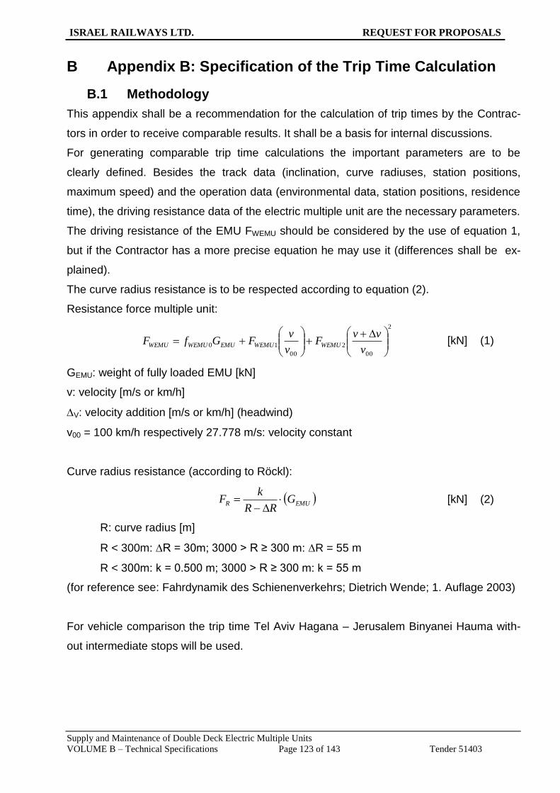
ISRAEL RAILWAYS LTD. REQUEST FOR PROPOSALS
Supply and Maintenance of Double Deck Electric Multiple Units
VOLUME B – Technical Specifications Page 123 of 143 Tender 51403
B Appendix B: Specification of the Trip Time Calculation
B.1 Methodology
This appendix shall be a recommendation for the calculation of trip times by the Contrac-
tors in order to receive comparable results. It shall be a basis for internal discussions.
For generating comparable trip time calculations the important parameters are to be
clearly defined. Besides the track data (inclination, curve radiuses, station positions,
maximum speed) and the operation data (environmental data, station positions, residence
time), the driving resistance data of the electric multiple unit are the necessary parameters.
The driving resistance of the EMU FWEMU should be considered by the use of equation 1,
but if the Contractor has a more precise equation he may use it (differences shall be ex-
plained).
The curve radius resistance is to be respected according to equation (2).
Resistance force multiple unit:
2
00
2
00
10
v
vvF
v
vFGfF WEMUWEMUEMUWEMUWEMU [kN] (1)
GEMU: weight of fully loaded EMU [kN]
v: velocity [m/s or km/h]
V: velocity addition [m/s or km/h] (headwind)
v00 = 100 km/h respectively 27.778 m/s: velocity constant
Curve radius resistance (according to Röckl):
EMUR GRR
kF
[kN] (2)
R: curve radius [m]
R < 300m: R = 30m; 3000 > R ≥ 300 m: R = 55 m
R < 300m: k = 0.500 m; 3000 > R ≥ 300 m: k = 55 m
(for reference see: Fahrdynamik des Schienenverkehrs; Dietrich Wende; 1. Auflage 2003)
For vehicle comparison the trip time Tel Aviv Hagana – Jerusalem Binyanei Hauma with-
out intermediate stops will be used.
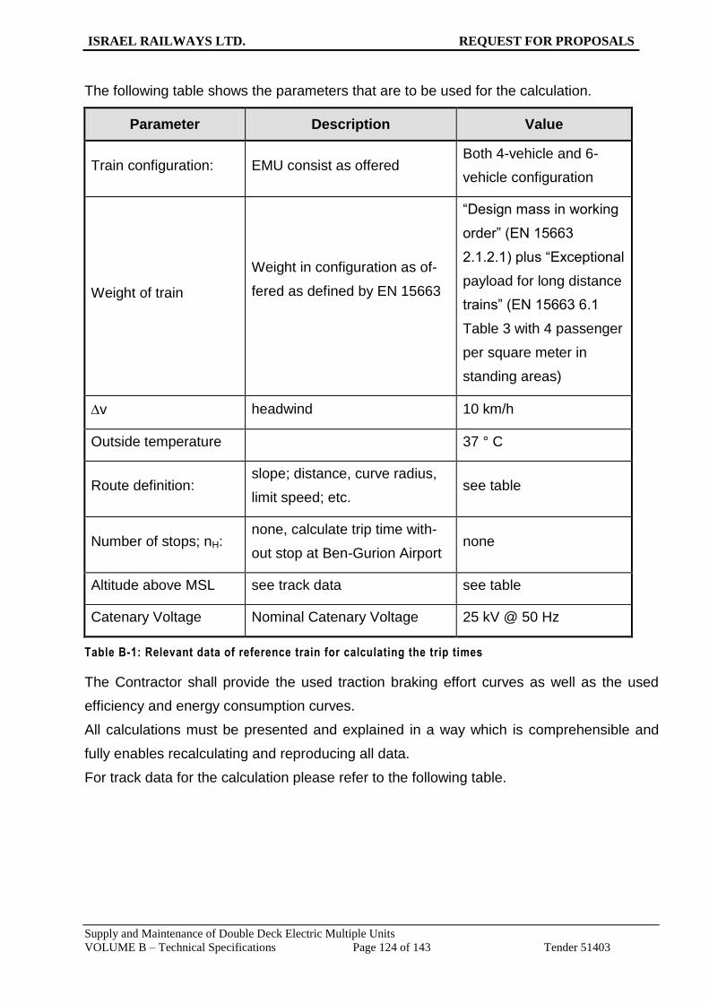
ISRAEL RAILWAYS LTD. REQUEST FOR PROPOSALS
Supply and Maintenance of Double Deck Electric Multiple Units
VOLUME B – Technical Specifications Page 124 of 143 Tender 51403
The following table shows the parameters that are to be used for the calculation.
Parameter Description Value
Train configuration: EMU consist as offered Both 4-vehicle and 6-
vehicle configuration
Weight of train
Weight in configuration as of-
fered as defined by EN 15663
“Design mass in working
order” (EN 15663
2.1.2.1) plus “Exceptional
payload for long distance
trains” (EN 15663 6.1
Table 3 with 4 passenger
per square meter in
standing areas)
v headwind 10 km/h
Outside temperature 37 ° C
Route definition: slope; distance, curve radius,
limit speed; etc. see table
Number of stops; nH: none, calculate trip time with-
out stop at Ben-Gurion Airport none
Altitude above MSL see track data see table
Catenary Voltage Nominal Catenary Voltage 25 kV @ 50 Hz
Table B-1: Relevant data of reference train for calculating the trip times
The Contractor shall provide the used traction braking effort curves as well as the used
efficiency and energy consumption curves.
All calculations must be presented and explained in a way which is comprehensible and
fully enables recalculating and reproducing all data.
For track data for the calculation please refer to the following table.
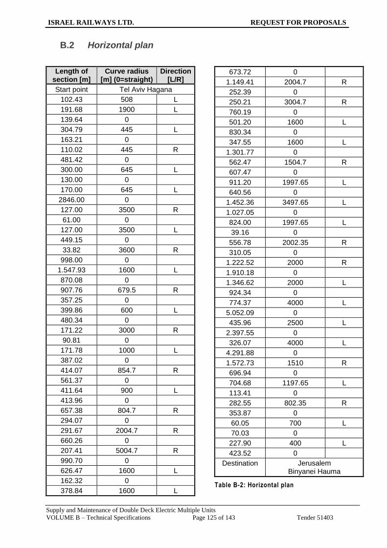
ISRAEL RAILWAYS LTD. REQUEST FOR PROPOSALS
Supply and Maintenance of Double Deck Electric Multiple Units
VOLUME B – Technical Specifications Page 125 of 143 Tender 51403
B.2 Horizontal plan
Direction [L/R]
Curve radius [m] (0=straight)
Length of section [m]
Tel Aviv Hagana Start point
L 508 102.43
L 1900 191.68
0 139.64
L 445 304.79
0 163.21
R 445 110.02
0 481.42
L 645 300.00
0 130.00
L 645 170.00
0 2846.00
R 3500 127.00
0 61.00
L 3500 127.00
0 449.15
R 3600 33.82
0 998.00
L 1600 1.547.93
0 870.08
R 679.5 907.76
0 357.25
L 600 399.86
0 480.34
R 3000 171.22
0 90.81
L 1000 171.78
0 387.02
R 854.7 414.07
0 561.37
L 900 411.64
0 413.96
R 804.7 657.38
0 294.07
R 2004.7 291.67
0 660.26
R 5004.7 207.41
0 990.70
L 1600 626.47
0 162.32
L 1600 378.84
0 673.72
R 2004.7 1.149.41
0 252.39
R 3004.7 250.21
0 760.19
L 1600 501.20
0 830.34
L 1600 347.55
0 1.301.77
R 1504.7 562.47
0 607.47
L 1997.65 911.20
0 640.56
L 3497.65 1.452.36
0 1.027.05
L 1997.65 824.00
0 39.16
R 2002.35 556.78
0 310.05
R 2000 1.222.52
0 1.910.18
L 2000 1.346.62
0 924.34
L 4000 774.37
0 5.052.09
L 2500 435.96
0 2.397.55
L 4000 326.07
0 4.291.88
R 1510 1.572.73
0 696.94
L 1197.65 704.68
0 113.41
R 802.35 282.55
0 353.87
L 700 60.05
0 70.03
L 400 227.90
0 423.52
Jerusalem Binyanei Hauma
Destination
Table B-2: Horizontal plan

ISRAEL RAILWAYS LTD. REQUEST FOR PROPOSALS
Supply and Maintenance of Double Deck Electric Multiple Units
VOLUME B – Technical Specifications Page 126 of 143 Tender 51403
B.3 Vertical plan
Gradient [‰] Length of section
[m]
Tel Aviv Hagana
0.56 93.19
5.72 622
5.29 41
2.77 112
1.5 38
0 212
1.86 125
4.17 175
7.32 188
0 400
1.16 196
0 0
1.16 200
2 1300
0 475
1.7 825
2 250
1 100
1.5 300
3.7 174
0 0
3.7 135
2.39 143
-7.48 297
-15 275
-4.48 1050
4.6 300
13.72 1005
Gradient [‰] Length of section
[m]
5.22 670
0 195
-15.05 465
-2.83 265
1.92 390
0 260
2 205
5.36 175
8.5 401
10.93 147
20.56 227
2.48 320
4.92 75
5.74 385
8.2 200
22 400
9 465
-4 534
8 416
0 300
-13 550
-6 200
7 210
11 950
0 250
-7 315
-3 350
-3.6 355
0 465

ISRAEL RAILWAYS LTD. REQUEST FOR PROPOSALS
Supply and Maintenance of Double Deck Electric Multiple Units
VOLUME B – Technical Specifications Page 127 of 143 Tender 51403
Gradient [‰] Length of section
[m]
7 870
12.5 1510
4 255
0 420
8 300
20 253
24 447
14.5 295
12.2 305
7.49 759.67
15.64 335.24
-1.29 1464.15
3.77 879.85
22.14 799.47
8.56 2574.23
18 290.27
28.95 2113.91
25.05 3517.66
21.5 1648.03
25.03 12603.36
18.96 1201.54
30 1349.43
13.1 511.38
2.02 499.7
Jerusalem Binyanei Hauma
Table B-2: Vertical plan

ISRAEL RAILWAYS LTD. REQUEST FOR PROPOSALS
Supply and Maintenance of Double Deck Electric Multiple Units
VOLUME B – Technical Specifications Page 128 of 143 Tender 51403
B.4 Speed Profile:
V-max
(km/h) Length (m)
Begin
absolute location (m)
60 1493.19 0
80 709 1493.19
150 3501.15 2202.19
140 123.3 5703.34
100 400 5826.64
150 2926.54 6226.64
100 5424.46 915318
160 37560.87 14577.64
120 818.09 52138.51
100 636.42 52956.6
70 130.08 53593.02
50 651.42 53723.1
0 54374.52
Table B-3: Speed Profile

ISRAEL RAILWAYS LTD. REQUEST FOR PROPOSALS
Supply and Maintenance of Double Deck Electric Multiple Units
VOLUME B – Technical Specifications Page 129 of 143 Tender 51403
C Appendix C: Running Dynamics
Safety - Track fatigue - Ride quality
Amended threshold values for test runs according to EN 14363. The values are only applicable as far as they
are part of the measurement method which has to be chosen in compliance with EN 14363.
Parameter Description LimitingValue
ΣY Sum of guiding forces Prud’homme 1)
ΣH Sum of lateral forces at axle boxes Prud’homme 2)
1) due to existing track quality, the factor k1 is 0.85 (instead of 1,0)
2) due to existing track quality, the factor k2 is 0.80 (instead of 0,9)
Table C-1: Running Dynamics

ISRAEL RAILWAYS LTD. REQUEST FOR PROPOSALS
Supply and Maintenance of Double Deck Electric Multiple Units
VOLUME B – Technical Specifications Page 130 of 143 Tender 51403
D Appendix D: Environmental Conditions
D.1 Climate and Environmental Conditions
Max. Ambient temp. 45 °C (shade)
Min Ambient temp. Minus 5 °C
Relative humidity 10% to 90%
Altitude - 400 m to +800 m
Sunny hours per year 3300 h
UV Radiation MJ/m² per year 360 - 600
Rainfall mm/year 400 - 800
D.2 Dust Concentrations in the Atmosphere
Maximum Half-hour Value Maximum Daily Value Average
NOx 1064 560 71
SO2 780 260 21
O3 312 143 84
Suspended Dust - 350 100
All values in micrograms per m³ atmosphere Particle Size to 0.5 - 1 micron
Table D-1: Suspended Particle Matter (SPM)
Special attention shall be paid to potential contamination by chalk dust from the track -bed.
D.3 Sea Salt Concentrations in the Atmosphere
Salt Element Na Cl SO4
Position Season Season Season
Dry Wet Dry Wet Dry Wet
Sea Air at Coastline 7.3 16.0 12.0 22.0 5.3 7.0
600 m from Shore 3.1 4.8 4.2 7.9 1.9 2.0
6000m from Shore 1.1 1.4 1.5 1.7 1.3 1.4
All values in micrograms per m³ atmosphere
Table D-2: Salt Concentrations in the Atmosphere

ISRAEL RAILWAYS LTD. REQUEST FOR PROPOSALS
Supply and Maintenance of Double Deck Electric Multiple Units
VOLUME B – Technical Specifications Page 131 of 143 Tender 51403
E Appendix E: Water Quality
No. Parameter Unit Range
1 Hardness ppm 220-450
2 pH 6.4-7.5
3 Chlorides ppm 20-400
4 Alkalinity ppm 100-300
5 Ca ppm 45-100
6 Cr ppb approx. 3
7 Cu ppb approx. 3
8 Fe ppb approx. 68
9 K ppm 2-5.7
10 Mg ppm 20-30
11 Mn ppm approx. 6
12 HCO3 ppm 110-400
Table E-1: Typical Water Quality in Israel

ISRAEL RAILWAYS LTD. REQUEST FOR PROPOSALS
Supply and Maintenance of Double Deck Electric Multiple Units
VOLUME B – Technical Specifications Page 132 of 143 Tender 51403
F Appendix F: Air Conditioning Performance
F.1 HVAC Passenger Area
This section contains a clause-by-clause modification of EN 13129-1:2002(E): Railway applications
- Air conditioning for main line rolling stock - Part 1: Comfort parameters.
Clause Existing Text Modification
4 air temperature according to Annex A air temperature according to ISR adapted of Annex A
4 air speed according to Annex B air speed according to ISR adapted Annex B
4 relative humidity according to Annex C relative humidity according to Annex C
5.1 The comfort conditions shall be satis-fied between the limits of the external conditions given in Annexes E.1 and E.2.
The comfort conditions shall be satis-fied between the limits of the external conditions given in ISR adapted An-nexes E.1 and E.2.
5.2 5 K below the minimum values and 5 K above the maximum values specified in Annex E
5 K below the minimum values and 5 K above the maximum values specified in ISR adapted Annex E.
5.2 if they are placed under the under-frame, 10 K above the maximum val-ues specified in Annex E.
if they are placed under the under-frame, 10 K above the maximum values specified in ISR adapted Annex E.
6.1.1 The contractual specifications shall define a regulation curve which shall be within the limits of the zone shown in Annex A.
The regulation curve is defined in the ISR adapted Annex A.
6.6 The air speed in the comfort areas shall be in the zones defined in Annex B according to prEN 13129-2.
The air speed in the comfort areas shall be in the zones defined in ISR adapted Annex B according to prEN 13129-2.
6.7.1 The total volume of fresh air added by forced ventilation to the comfort areas shall be in accordance with the values defined in Annex F.
The total volume of fresh air added by forced ventilation to the comfort areas shall be in accordance with the values defined in ISR adapted Annex F.
6.7.2 A re-circulated air system shall ensure the operation (even in a degraded con-dition) if the design of the vehicle can permit the fresh air intakes to be tem-porarily blocked.
In case of a failure in the cooling circuit, the ventilation system will continue it’s function of circulating the cabin air and supplying fresh air.
7 Within the performance defined in clause 8, it shall be possible to vary the temperature setting in each comfort area independently of the other areas by means of a control device that gives a minimum range of regulation of ± 2 K (+ 2 K and - 4 K for couchette coaches and sleeping cars) around the tempera-tures specified in clause 6.
Within the performance defined in clause 8, it shall be possible for the crew to vary the temperature setting in each comfort area independently of the other areas by means of a control de-vice that gives a minimum range of regulation of ± 3 K.
8.1 The preheating time is a question of exploitation which shall be specified by
ISR requires a preheating time of 30 minutes from 0°C to 18°C.

ISRAEL RAILWAYS LTD. REQUEST FOR PROPOSALS
Supply and Maintenance of Double Deck Electric Multiple Units
VOLUME B – Technical Specifications Page 133 of 143 Tender 51403
Clause Existing Text Modification
the operator.
8.2 At the minimum external temperature for the climatic zone (see Annex E) defined in the contractual specifica-tions, the mean interior temperature shall be greater than or equal to + 22 ° C in commercial service without pas-sengers and solar radiation.
At the minimum external temperature (see ISR adapted Annex E), the mean interior temperature shall be greater than or equal to + 22 ° C in commercial service without
passengers and solar radiation.
8.3 The precooling time is a question of exploitation which shall be specified by the operator.
ISR requires a precooling time of 30 minutes from 40°C to 27°C.
8.4 At the maximum exterior temperature of the climatic zone (see Annexes E.1 and E.2) defined in the contractual specifications, the mean interior tem-perature (Tim) shall be equal to the normal interior temperature setting (Tic) specified in 6.1.1 in commercial service with all seats occupied and solar gain.
At the maximum exterior temperature (see ISR adapted Annexes E.1 and E.2), the mean interior temperature (Tim) shall be equal to the normal inte-rior temperature setting (Tic) specified in 6.1.1 in commercial service with all seats occupied, solar gain and 2 stand-ees/m2.
9.1.1 The coefficient k for the vehicle shall be less than or equal to the values accord-ing to Table 1:
The coefficient k for the vehicle shall be less than or equal to 2 W/m2K at stand-still.
9.4 With stationary vehicles, the overall level of noise generated by the air con-ditioning installation alone in the com-fort areas, shall not exceed the values in Table 2:
With stationary vehicles, the overall level of noise generated by the air con-ditioning installation alone in the com-fort areas shall be quoted by the Bidder in the tender documents.
9.7 When the contract specification re-quires it, the vehicle and its air condi-tioning unit shall be fitted in a manner that undue tympanic pressure varia-tions do not occur).
Required
9.9.1 The value of MDBF (Mean Distance Between Failures) shall be as defined in the contract specification of the air conditioning installation.
The value of MDBF (Mean Distance Between Failures) shall be quoted by the Bidder at the time of tender.
Annex A Refer to EN13129-1 Replace with ISR adapted Annex A
Annex B Refer to EN13129-1 Replace with ISR adapted Annex B
Annex C Refer to EN13129-1 Identical to EN13129-1
Annex D Refer to EN13129-1 Identical to EN13129-1
Annex E.1 Refer to EN13129-1 Table E.1 – Winter
Minimum exterior temperatures 0°C
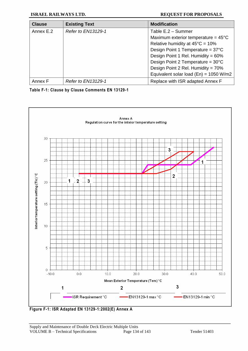
ISRAEL RAILWAYS LTD. REQUEST FOR PROPOSALS
Supply and Maintenance of Double Deck Electric Multiple Units
VOLUME B – Technical Specifications Page 134 of 143 Tender 51403
Clause Existing Text Modification
Annex E.2 Refer to EN13129-1 Table E.2 – Summer
Maximum exterior temperature = 45°C
Relative humidity at 45°C = 10%
Design Point 1 Temperature = 37°C
Design Point 1 Rel. Humidity = 60%
Design Point 2 Temperature = 30°C
Design Point 2 Rel. Humidity = 70%
Equivalent solar load (En) = 1050 W/m2
Annex F Refer to EN13129-1 Replace with ISR adapted Annex F
Table F-1: Clause by Clause Comments EN 13129-1
Figure F-1: ISR Adapted EN 13129-1:2002(E) Annex A

ISRAEL RAILWAYS LTD. REQUEST FOR PROPOSALS
Supply and Maintenance of Double Deck Electric Multiple Units
VOLUME B – Technical Specifications Page 135 of 143 Tender 51403
Annex B
Permissible air speed
0
0.1
0.2
0.3
0.4
0.5
0.6
0.7
0.8
0.9
1
18.0 20.0 22.0 24.0 26.0 28.0 30.0
Mean interior temperature (Tim) °C
Air
sp
eed
m/s
ISR min m/s ISR max m/s EN 13129-1 min m/s EN 13129-1 max m/s
1
22
1
3
3
1 2 3
44
4
Figure F-2: ISR Adapted EN 13129-1:2002(E) Annex B

ISRAEL RAILWAYS LTD. REQUEST FOR PROPOSALS
Supply and Maintenance of Double Deck Electric Multiple Units
VOLUME B – Technical Specifications Page 136 of 143 Tender 51403
Figure F-3: ISR Adapted EN 13129-1:2002(E) Annex F
Clause by clause Modification to EN 13129-2:2004(E) : Railway applications - Air conditioning for
main line rolling stock - Part 2: Type tests
Clause Existing Text Recommended Modification
6.4.2.1 The tests shall be carried out at the temperatures given in Table 1:
The tests shall be carried out at the following temperatures:
0 °C
+10 °C
6.4.3.1 The tests shall be carried out at the external climatic conditions given in
The tests shall be carried out at the external climatic conditions given below:

ISRAEL RAILWAYS LTD. REQUEST FOR PROPOSALS
Supply and Maintenance of Double Deck Electric Multiple Units
VOLUME B – Technical Specifications Page 137 of 143 Tender 51403
Clause Existing Text Recommended Modification
Table 2: Dry bulb
temperature
Relative
humidity
Equivalent solar
radiation (En)
°C % RH W/m2
30 70 1050
37 60 1050
47 10 1050
8.4 The measurement of noise and vibra-tion shall be carried out on a station-ary vehicle with the air conditioning installation functioning at a level which corresponds to the maximum performance conditions of the cus-tomer’s specification.
The measurement of noise and vibration shall be carried out on a stationary vehicle with the air conditioning installation functioning at maximum performance conditions:
18 m3/h Fresh air flow rate
Cooling forced to maximum (set point not achievable)
Annex A
Table A.1 – Tests in heating mode (Zone I – Winter)
Table A.1 – Tests in heating mode (Israel)
Use:
Mean exterior temperature (Tem) 0°C
Instead of:
Mean exterior temperature (Tem) –10°C
Annex A
Table A.1 – Tests in heating mode (Zone I – Winter)
Table A.1 – Tests in heating mode (Israel)
Use:
Air speed 160 km/h
Instead of:
120 km/h
Annex A
Table A.2 – Variable external tem-perature tests (Zone I – Summer)
Table A.2 – Variable external temperature tests (Israel)
100% occupancy means: full seating + 2 standees / m2
Annex A
Table A.3 — Tests in cooling mode (Zone I − Summer)
Table A.3 — Tests in cooling mode (Israel)
100% occupancy means: full seating + 2 standees / m2
Use the following test conditions:
30°C instead of 28°C
37°C instead of 40°C
47°C instead of “+45 or +50” °C
Air speed 160 km/h instead of 120 km/h
Dry bulb
temperature
Relative
humidity
Equivalent solar
radiation (En)
°C % RH W/m2
30 70 1050
37 60 1050
47 10 1050
Table F-2: Clause by Clause Comments EN 13129-2

ISRAEL RAILWAYS LTD. REQUEST FOR PROPOSALS
Supply and Maintenance of Double Deck Electric Multiple Units
VOLUME B – Technical Specifications Page 138 of 143 Tender 51403
F.2 HVAC Driver’s Cab
Modifications to AC-Standard of driving cabs:
Clause by clause modification to EN 14813-1:2006+A1:2010(E):
Clause Existing Text Modification
4 Driving cab classification The driver’s cab shall be designed in
accordance with the requirements for
category A.
7.2 preheating time to be
defined in agreement
preheating of the driver’s cab at minimum
exterior temperature as defined in
Appendix D to Tim as defined in 7.1 shall
not take more than 30 minutes
7.3 maximum interior
temperature
the maximum interior temperature under all
climatic conditions as defined in Appendix
D with solar load, at full speed and with two
occupants shall not exceed 27 ° C
7.4 precooling time to be
defined in agreement
precooling of the driver’s cab at maximum
exterior temperature and maximum solar
load as defined in Appendix D to 27 °C
shall not take more than 30 minutes
7.5 stand by operation to be
defined in agreement
a parking mode feature of the driver’s cab
air conditioning system shall be provided
keeping the maximum interior temperature
at 30 °C under the conditions as defined in
7.4 and the minimum temperature at 10 °C
under the conditions as defined in 7.1
8.2 interior temperature
settings
the temperature control shall relate to the
exterior temperature as defined in
paragraph 8.2.3 of EN 14813-1
9.5 air speed the air speed nozzles, facing the driver,
shall not exceed 0.3 m/s
9.6.1 the minimum fresh airflow
rate of 30 m³/h/person is
sufficient
the minimum fresh airflow rate shall be 60
m³/h
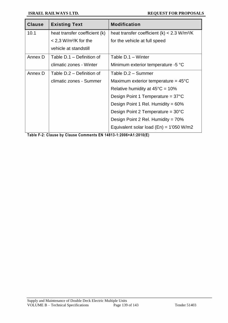
ISRAEL RAILWAYS LTD. REQUEST FOR PROPOSALS
Supply and Maintenance of Double Deck Electric Multiple Units
VOLUME B – Technical Specifications Page 139 of 143 Tender 51403
Clause Existing Text Modification
10.1 heat transfer coefficient (k)
< 2,3 W/m²/K for the
vehicle at standstill
heat transfer coefficient (k) < 2.3 W/m²/K
for the vehicle at full speed
Annex D Table D.1 – Definition of
climatic zones - Winter
Table D.1 – Winter
Minimum exterior temperature -5 °C
Annex D Table D.2 – Definition of
climatic zones - Summer
Table D.2 – Summer
Maximum exterior temperature = 45°C
Relative humidity at 45°C = 10%
Design Point 1 Temperature = 37°C
Design Point 1 Rel. Humidity = 60%
Design Point 2 Temperature = 30°C
Design Point 2 Rel. Humidity = 70%
Equivalent solar load (En) = 1'050 W/m2
Table F-2: Clause by Clause Comments EN 14813-1:2006+A1:2010(E)

ISRAEL RAILWAYS LTD. REQUEST FOR PROPOSALS
Supply and Maintenance of Double Deck Electric Multiple Units
VOLUME B – Technical Specifications Page 140 of 143 Tender 51403
G Appendix G: System Requirements
G.1 System layout
Figure G-1: Actual Passenger Network of Israel Railway

ISRAEL RAILWAYS LTD. REQUEST FOR PROPOSALS
Supply and Maintenance of Double Deck Electric Multiple Units
VOLUME B – Technical Specifications Page 141 of 143 Tender 51403
G.2 Distances between Passenger Stations
INTERCITY SERVICE STATION DISTANCE m
NAHARIYYA
8'770
ACCO
10'371
QIRYAT MOTZKIN
2'309
QURYAT HAIM *
1'925
HUTZOT HAMIFRATZ *
2'377
LEV HAMIFRATZ
5'137
HAIFA MERKAZ
1'720
HAIFA BAT GALIM
5'733
HAIFA HOF HACARMEL
11'581
ATLIT *
20'705
BINYAMINA
3'289
QESYRYYA-PARDES HANNA *
7'688
HADERA MAARAV *
13'757
NETANYA *
6'470
BE YEHOSUHUA *
11'605
HERZLIYYA *
6'985
T.A. UNIVERSITY
2'318
T.A. MERKAZ
1'290
T.A. HASHALOM
2'337
T.A. HAHAGANA
9'615
BEN-GURION AIRPORT
TOTAL 135'982
T.A. MERKAZ
1'290
T.A. HASHALOM
2'337
T.A. HAHAGANA
16'578
LOD
42'334
QIRYAT GAT
BE'ER SHEVA
40'221
TZAFON\UNIVERSITY
5'270
BE'ER SHEVA MERKAZ
TOTAL 108'030
Remarks:
1. Some of the intercity trains may be stoppin in stations marked with *
2. Intercity train Nahariyya - Be'er Sheva Merkaz total distance 230.770 km
NAHARIYYA - HAIFA -
TEL AVIV -
BEN-GURION AIRPORT
TEL AVIV - BE'ER SHEVA
Table G-1: Distances between passenger stations

ISRAEL RAILWAYS LTD. REQUEST FOR PROPOSALS
Supply and Maintenance of Double Deck Electric Multiple Units
VOLUME B – Technical Specifications Page 142 of 143 Tender 51403
H Appendix H: Technical Requirements for Electronic Equipment
H.1 Ambient Temperature (supplementary to EN 50155, Paragraph 2.1.2)
Electronic devices must be dimensioned and produced thus the entire specified operating requirements on
the operations behaviour will be met for a temperature class added to EN 50155. The values are specified in
the following table:
Column 1 Column 2 Column 3 Column 4
Category Outside ambient
temperature
Inside cabinet
temperature
Inside cabinet
excess tempera-
ture 10 min
Temperature of
ambient air of
printed circuit
board assembly
Tx -5... +45 C -5... +70°C 15°C -10... +85°C
Table H-1: Ambient Temperature
Devices which are arranged at the exterior of the Unit and such which are required for putting the Unit into
service must additionally fulfil the following conditions:
Temperature area of -10 to -15 °C, short-time operation (10 min) without observing
tolerances.
Deviations should be with impact to the safe side.
Temperature area of -15 to -20 °C – no irreversible damages at switched-off devices
H.2 Special Service Conditions (supplementary to EN 50155, Para-graph 2.2)
Atmospheric influences:
In dependence on the position and arrangement in the Unit, the devices have to work even in case of wind,
sand storm, rainfall and shower water, pollution of the ambient air by dust, smoke, aggressive gases and
steaming, salt mist, etc. Moreover impacts of plant and animal microbes have to be considered, if so, a filtr a-
tion is to be envisaged.
H.3 Testing
Dimension testing according to EN 50155:

ISRAEL RAILWAYS LTD. REQUEST FOR PROPOSALS
Supply and Maintenance of Double Deck Electric Multiple Units
VOLUME B – Technical Specifications Page 143 of 143 Tender 51403
The dimension testing has to evaluate whether the fitting dimensions are within the tolerance of the specified
nominal size.
The following has to be tested:
outer dimensions
dimensions of connectors and fittings (mechanical interfaces, except for component)