temprite digital control system manual standard and...
TRANSCRIPT

1
TracRite
Digital Control System
User Manual
Touchscreen Systems
Rev. 10-29-15

2

3
Table of Contents
OVERVIEW ...................................................................................................................................... 8
NETWORKING .............................................................................................................................. 9
TRACRITE DEFAULT SETTINGS ...................................................................................... 9
Unit Operating Modes ........................................................................................................... 10
MRT Controls .......................................................................................................................... 10 UNIT OFF MODE ............................................................................................................................................. 11 UNIT MANUAL MODE ................................................................................................................................... 11 UNIT AUTO MODE ......................................................................................................................................... 11
MRT-Touch Controls .............................................................................................................. 11 UNIT OFF MODE ............................................................................................................................................. 11 UNIT MANUAL MODE ................................................................................................................................... 11 UNIT AUTO MODE ......................................................................................................................................... 11 Scheduling Time Clock .......................................................................................................................................... 12 Heating Night Setback........................................................................................................................................ 15 Cooling Night Setback........................................................................................................................................ 15 Auxiliary Unit Enable ........................................................................................................................................ 15 Network Enable…. ............................................................................................................................................. 15
MDT Controls .......................................................................................................................... 15 UNIT OFF MODE ............................................................................................................................................. 16 UNIT MANUAL MODE ................................................................................................................................... 16 UNIT AUTO MODE ......................................................................................................................................... 16
MDT-Touch Controls .............................................................................................................. 16 UNIT OFF MODE ............................................................................................................................................. 16 UNIT MANUAL MODE ................................................................................................................................... 16 UNIT AUTO MODE ......................................................................................................................................... 16 Scheduling Time Clock .......................................................................................................................................... 16 Auxiliary Unit Enable ........................................................................................................................................ 19 Network Enable…. ............................................................................................................................................. 19
Heating/Ventilation/Cooling Operating Modes ..................................................... 20
Heating Mode (MRT) ................................................................................................................ 20 Overview………… ............................................................................................................................................ 20 Room Sensor Failsafe ............................................................................................................................................ 20 Cooldown Period… ............................................................................................................................................ 20 Setpoints…………. ............................................................................................................................................ 20 General Burner Control ...................................................................................................................................... 20 Energy Savings Mode 1 Mixing Box Recirculating Units .............................................................................. 21 Energy Savings Mode 1 Non-Recirculating Units .......................................................................................... 21 Energy Savings Mode 2 Mixing Box Recirculating Direct-Fired Units ......................................................... 21 Energy Savings Mode 3 ..................................................................................................................................... 21 Recirculating Direct-Fired Heaters ................................................................................................................... 22
Heating Mode (MRT-Touch) ................................................................................................... 22 Overview………… ............................................................................................................................................ 22 Room Sensor Failsafe ............................................................................................................................................ 22 Cooldown Period… ............................................................................................................................................ 23 Setpoints………… ............................................................................................................................................. 23 Occupied Mode…. ............................................................................................................................................. 23 Unoccupied / Night Setback Mode ..................................................................................................................... 23

4
Optimal Start……. ............................................................................................................................................. 23 General Burner Control ...................................................................................................................................... 24 Energy Savings Mode 1 Mixing Box Recirculating Units .............................................................................. 25 Energy Savings Mode 1 Non-Recirculating Units .......................................................................................... 25 Energy Savings Mode 2 Mixing Box Recirculating Direct-Fired Units ......................................................... 25 Energy Savings Mode 3 ..................................................................................................................................... 25 Recirculating Direct-Fired Heaters ................................................................................................................... 25
Heating Mode (MDT) ................................................................................................................ 26 Overview………… ............................................................................................................................................ 26 Setpoints………… ............................................................................................................................................. 26 General Burner Control ...................................................................................................................................... 27 Energy Savings Mode 2 Mixing Box Recirculating Direct-Fired Units ......................................................... 27 Energy Savings Mode 3 ..................................................................................................................................... 27 Recirculating Direct-Fired Heaters ................................................................................................................... 27
Heating Mode (MDT-Touch) ................................................................................................... 28 Overview………… ............................................................................................................................................ 28 Setpoints………… ............................................................................................................................................. 28 Scheduled On Mode ........................................................................................................................................... 28 Scheduled Off Mode .......................................................................................................................................... 28 General Burner Control ...................................................................................................................................... 28 Energy Savings Mode 2 Mixing Box Recirculating Direct-Fired Units ......................................................... 28 Energy Savings Mode 3 ..................................................................................................................................... 28 Recirculating Direct-Fired Heaters ................................................................................................................... 28
Ventilation Mode ........................................................................................................................ 29
Cooling Mode (MRT) ................................................................................................................ 32 Overview………… ............................................................................................................................................ 32 Room Sensor Failsafe ............................................................................................................................................ 32 Setpoints………… ............................................................................................................................................. 32 General Cooling Control ....................................................................................................................................... 32 Two Stage Cooling Cycling Sequence .................................................................................................................. 33 Four Stage Cooling Cycling Sequence .................................................................................................................. 33 Energy Savings Mode 4 ..................................................................................................................................... 33
Cooling Mode (MRT-Touch) .................................................................................................... 33 Overview………… ............................................................................................................................................ 33 Room Sensor Failsafe ............................................................................................................................................ 33 Setpoints…………. ............................................................................................................................................ 33 Occupied Mode…. ............................................................................................................................................. 34 Unoccupied / Night Setback Mode ..................................................................................................................... 34 Optimal Start……. ............................................................................................................................................. 34 General Cooling Control ....................................................................................................................................... 35 Two Stage Cooling Cycling Sequence .................................................................................................................. 35 Four Stage Cooling Cycling Sequence .................................................................................................................. 36 Energy Savings Mode 4 ..................................................................................................................................... 36
Cooling Mode (MDT) ................................................................................................................ 36 Overview………… ............................................................................................................................................ 36 Setpoints………… ............................................................................................................................................. 36 General Cooling Control ....................................................................................................................................... 37 Two Stage Cooling Cycling Sequence .................................................................................................................. 37 Four Stage Cooling Cycling Sequence .................................................................................................................. 37 Energy Savings Mode 4 ..................................................................................................................................... 37
Cooling Mode (MDT-Touch) .................................................................................................... 37 Overview…………. ........................................................................................................................................... 37 Setpoints………… ............................................................................................................................................. 37 Scheduled On Mode ........................................................................................................................................... 37 Scheduled Off Mode .......................................................................................................................................... 38 General Cooling Control ....................................................................................................................................... 38

5
Two Stage Cooling Cycling Sequence .................................................................................................................. 38 Four Stage Cooling Cycling Sequence .................................................................................................................. 38 Energy Savings Mode 4 ..................................................................................................................................... 38
Damper Control Modes ........................................................................................................ 39
Overview ..................................................................................................................................... 39 Minimum Ventilation ......................................................................................................................................... 39
Manual Mode ............................................................................................................................. 39 MRT and MDT Controls ....................................................................................................................................... 40 MRT-Touch and MDT-Touch Controls ............................................................................................................... 40
Mixed Air Temperature Mode ............................................................................................... 40 MDT and MDT-Touch Controls ........................................................................................................................ 41 MRT Controls…… ................................................................................................................................................ 41 MRT-Touch Controls ............................................................................................................................................ 41
Building Pressure Mode ........................................................................................................... 41 MRT and MDT Controls ....................................................................................................................................... 41 MRT-Touch and MDT-Touch Controls ............................................................................................................... 41
100% Outside Air Mode ........................................................................................................... 41 MRT, MRT-Touch, MDT, and MDT-Touch Controls ......................................................................................... 42
Freezestat ..................................................................................................................................... 42
Clogged Filter............................................................................................................................. 42
Multiplexed Inputs .................................................................................................................. 43
Equipment Touch User Guide.......................................................................................... 44
Navigation ................................................................................................................................ 44 Overview………… ............................................................................................................................................ 44 Changing Setpoints and Other Editable Values .................................................................................................... 45 Home Screen……. ............................................................................................................................................. 45 Login Screen……. ............................................................................................................................................. 46 Menu Screen……............................................................................................................................................... 47 Status Screen……. ............................................................................................................................................. 48 Cycles and Runtimes Screen .............................................................................................................................. 49 Setpoints Screen…. ............................................................................................................................................ 50 Optimal Start Screen .......................................................................................................................................... 51 Schedules Screen… ............................................................................................................................................ 52 Trends Screen……. ............................................................................................................................................... 53 Modes Screen……. ............................................................................................................................................ 54 Unit Setup Screen ............................................................................................................................................... 55 Brand Configuration Screen ............................................................................................................................... 56 Resets Screen……. ............................................................................................................................................ 57 Calibration Screen .............................................................................................................................................. 61 Energy Reports Screen ....................................................................................................................................... 62 Electricity Data Screen ....................................................................................................................................... 63 Fuel Data Screen… ................................................................................................................................................ 64 CO2 Data Screen… ............................................................................................................................................ 65 User Configured Output Help Screen ................................................................................................................. 66 User Configured Output Setup Screen ............................................................................................................... 66 Module Status (Modstat) Screen ........................................................................................................................ 71 IOM (Installation, Operation, and Maintenance Manual) Screen ....................................................................... 72 Archive Procedure Screen .................................................................................................................................. 74 Archive Screen…. ................................................................................................................................................. 74

6
System Screen…… ............................................................................................................................................ 79 Alarms Screen…… ............................................................................................................................................ 79 Setup Screen……. .............................................................................................................................................. 80 Module Setup Screen ......................................................................................................................................... 81 Touchscreen Setup Screen ................................................................................................................................. 81 Browser Screen…. ............................................................................................................................................. 82 Set Time and Date Screen .................................................................................................................................. 84 Communication (BACnet) Screen ...................................................................................................................... 84
Protocol Setup ........................................................................................................................... 86
BACnet MS/TP ....................................................................................................................... 86
Modbus ........................................................................................................................................ 87
N2 ................................................................................................................................................. 88
LonWorks .................................................................................................................................... 88
Diagnostics – Critical Alarm Codes ......................................................................... 90
ALARM CODE: Freezestat ................................................................................................... 90 SOLUTION: If burner was operating prior to shutdown (check prior alarm log) ....................................... 90 SOLUTION: If burner was not operating prior to shutdown (check prior alarm log) ................................. 91
ALARM CODE: Burner Hand ............................................................................................... 93 SOLUTION: Inspect burner control circuit. This alarm has the potential to be a very serious problem. Close the manual gas valves immediately if the fan is not running .................................................................... 93
ALARM CODE: Flame Failure ............................................................................................. 94 SOLUTION: Investigate flame relay ........................................................................................................ 94
Diagnostics – Non-Critical Alarm Codes ............................................................... 94
ALARM CODE: Unit Off/Fan On .......................................................................................... 94 SOLUTION: If fan is running ................................................................................................................... 94 SOLUTION: If fan is not running ................................................................................................................ 95
ALARM CODE: Unit On/Fan Off .......................................................................................... 95 SOLUTION: If fan/motor is running......................................................................................................... 95 SOLUTION: If fan/motor is not running .................................................................................................. 95
ALARM CODE: Check Airflow Switches ............................................................................ 96 SOLUTION: If high airflow switch is opening. Do not adjust the switch setpoints .................................. 96 SOLUTION: If low airflow switch is opening. Do not adjust the switch setpoints .................................... 96
ALARM CODE: Clogged Filters ......................................................................................... 97 SOLUTION: If clogged filter switch is closing ......................................................................................... 97
ALARM CODE: Safety Circuit Open ................................................................................... 98 SOLUTION: If fan is not running (check prior alarm log) .......................................................................... 98 SOLUTION: If fan is running (check prior alarm log) ................................................................................ 98
ALARM CODE: Burner Status Alert .................................................................................. 99 SOLUTION: Inspect burner control circuit and burner ............................................................................... 99
ALARM CODE: Insufficient Outside Air ............................................................................ 99 SOLUTION: If heat is desired ................................................................................................................... 99 SOLUTION: If less outside air is desired ................................................................................................ 100
ALARM CODE: Room Sensor Failure ............................................................................ 101 SOLUTION: Investigate room sensor ..................................................................................................... 101
ALARM CODE: Invalid Damper Control Mode .............................................................. 101

7
SOLUTION: If the unit is configured for MRT or MRT-Expert controls ............................................... 101 SOLUTION: If the unit is configured for MDT or MDT-Expert controls .............................................. 101
ALARM CODE: Monthly/Quarterly/Yearly Maintenance Reminder (See IOM) ........ 102 SOLUTION: If an active maintance reminder alarm is present: ............................................................... 102
Glossary ....................................................................................................................................... 102
Appendix A ........................................................................................................................... 103
10KΩ Thermistor Output Curve ......................................................................................... 103
Appendix B ........................................................................................................................... 104
Airflow Station Layout ............................................................................................................. 104
Appendix C ........................................................................................................................... 105
I/O Zone 583 Controller Specifications ............................................................................... 105
Appendix D ........................................................................................................................... 106
I/O Zone 583 Controller Battery Checkout ......................................................................... 106
Appendix E ........................................................................................................................... 107
I/O Flex 6126 Controller Specifications ............................................................................... 107
Appendix F ........................................................................................................................... 108
I/O Flex 6126 Controller Battery Checkout ......................................................................... 108
Appendix G ........................................................................................................................... 109
Control System Field Conversion ......................................................................................... 109
Appendix H ........................................................................................................................... 109
Heating and Cooling Design Temperatures ....................................................................... 109
Appendix J ........................................................................................................................... 114
Room Sensor Wiring ............................................................................................................ 114
Appendix K ........................................................................................................................... 115
Equipment Touch Wiring ........................................................................................................ 115 Portable / Using the Terminal Plug .................................................................................................................. 115 Hard-Wired / No Terminal Plug ....................................................................................................................... 116

8
OVERVIEW A glossary has been provided to assist the reader in understanding distinctive terms and phrases. These terms and phrases appear in italics. The terms “unoccupied” and “night setback” are used interchangeably in this manual to refer to all time periods in the unit’s operating schedule outside of the occupied period time range. The terms “supply air” and “discharge air” are used interchangeably in this manual to refer to the conditioned air that leaves the unit through the discharge opening.
Temprite’s Digital Control System, TracRite, is designed to give the user the ultimate in unit performance and operational flexibility, adaptability, and reliability in a user-friendly package. The TracRite DDC system is a standard component on Temprite heating and cooling units. Because the TracRite system encompasses a wide variety of unit types, not all of the system’s capabilities and functions are relevant to all units. Where a function is similar but different between recirculating and non- recirculating units or direct fired or indirect fired units, the function is explained separately.
TracRite accepts single or multiple units on the system network. Each unit can be provided with an Equipment Touch touchscreen interface. The Equipment Touch connects to the unit control module via the Equipment Touch remote terminal plug. The operating parameters for individual units may be input through the Equipment Touch. A PC may also be connected to the network. This allows the user to configure each unit separately, or all units can be configured simultaneously. A controls contractor can provide assistance in networking.
The Equipment Touch ships with a cable. One end of the cable is pre-wired to the terminal connectors on the back of the Equipment Touch while the other end consists of a 4-pole plug connector that plugs directly into terminal blocks in the unit’s main control panel.
It is easy to move the Equipment Touch between units without having to do any additional wiring. Simply unplug the Equipment Touch plug from the Equipment Touch remote terminal plug connection and plug it into the remote terminal plug connection on another unit.
Temprite’s TracRite system also includes operational modes such as time scheduling, filter monitoring, and multiple damper control and temperature control schemes. All of these modes provide the maximum in unit operational flexibility.
The optional airflow station imparts unparalleled adaptability into the operation of each unit. A daily self-calibration enables TracRite to detect the exact ratio of outside and return air entering the unit. Then TracRite daily fine-tunes the unit’s operation based on these new parameters. Air volume can vary because of changes in static pressure conditions due to loading filters, VAV boxes, and building dynamics. These varying conditions influence the ventilation air provided by the unit. On certain models of recirculating direct-fired heaters this impacts the allowable equivalent temperature rise of the unit that is allowed under the latest ANSI standard for direct-fired heaters.
TracRite diagnostic capabilities insure swift response to abnormal unit conditions. An alarm is generated anytime a discrepancy exists between operational parameters and

9
actual unit operation. An alarm indication is displayed at the Equipment Touch as a red icon with a white exclamation mark (!) and at a system PC in text format. In the Diagnostics section of this manual is a list of all alarms and possible causes and solutions.
All of the features of the TracRite system are designed to provide the user with real time information. At any time the user can display all of the operational parameters, make changes, if necessary, and observe the various temperature, pressure, and damper readings. The system’s diagnostic capabilities provide the user with up to the minute status reporting. (Equipment Touch touchscreen or WebCTRL internet connection is required for these features.)
NETWORKING TracRite is adaptable to a variety of different network architectures and protocols. Each controller has built-in protocol translation and can be configured for operation on ARC156 or EIA-485 communication networks. See Appendix C (I/O Zone 583) or E (I/O Flex 6126) for specific controller specifications.
The TracRite system can be connected to most existing building automation systems. Some systems may require the use of special controllers and network communication devices.
TRACRITE DEFAULT SETTINGS The following is a list of TracRite DDC controller defaults. These are the default operating parameters set at the factory prior to shipment.
ITEM DEFAULT RANGE Unit Network Address varies 000 – 100 rotary switches Unit Operating Mode Off Off – Manual – Auto Control System As specified MRT (modulating room
temperature control) – MDT (modulating discharge temperature control)
Time Clock Schedule None User Configurable Damper Operating Mode As specified Manual – Building Pressure –
Mixed Air Temperature Fuel Selection As specified Natural Gas – Propane Heating Unoccupied Setpoint 55°F 40°F - 130°FCooling Unoccupied Setpoint 100°F 40°F - 130°FHeating Occupied Setpoint 65°F 40°F - 130°FCooling Occupied Setpoint 73°F 40°F - 130°F Freezestat 45°F 35°F - 80°FFreezestat Buffer Time 3 minutes 3 - 9 minutesHeating Economizer Setpoint 65°F 40°F - 130°FCooling Economizer Setpoint 55°F 40°F - 130°FMinimum Heating Discharge Temperature Setpoint
55°F 40°F - 130°F
Maximum Heating Discharge Temperature Setpoint
100°F 40°F - 130°F

10
ITEM DEFAULT RANGE Minimum Cooling Discharge Temperature Setpoint
55°F 40°F - 130°F
Maximum Cooling Discharge Temperature Setpoint
75°F 40°F - 130°F
Mixed Air Temperature Setpoint 50°F 30°F - 90°F Building Pressure Setpoint 0.00” W. C. -0.05” - +0.05” W. C. Manual Damper Position Setpoint 20% Outside Air 0% - 100%Minimum Ventilation Setpoint 20% Outside Air 0% - 100%Manual Damper Position Setpoint (75/25 direct fired heaters)
25% Outside Air 25% - 100%
Minimum Ventilation Setpoint (75/25 direct fired heaters)
25% Outside Air 25% - 100%
Duct Heater Size As specified GTD-160 – GTD-320 – GTD-480
User PID Select Direct Acting Direct Acting – Reverse Acting
High Input Value 0.00 -9999.99 – 99999.99 Low Input Value 0.00 -9999.99 – 99999.99 User Control Setpoint 0.00 -9999.99 – 99999.99 Maximum User Setpoint 0.00 -9999.99 – 99999.99 Minimum User Setpoint 0.00 -9999.99 – 99999.99 Optimal Start Limit Setpoint 0 hours 0 – 6 hours Heating Design Temperature Setpoint
22°F -40°F - 130°F
Heating Capacity Setpoint 5°F/hr Adjusts automatically Cooling Design Temperature Setpoint
100°F -40°F - 130°F
Cooling Capacity Setpoint 5°F/hr Adjusts automatically
Unit Operating Modes There are three different modes that control the supply fan and unit operation:
Off Manual Auto
There are three different methods for controlling the operating modes: a remote control panel with one or two rotating adjustment knobs (MRT and
MDT controls) an Equipment Touch touchscreen panel with backlit display (MRT-Touch and
MDT-Touch controls) an internet-based WebCTRL interface or other 3rd party building automation
system
MRT Controls Modulating room temperature (MRT) control is the most basic TracRite control for room temperature. The MRT control system includes a remote control panel equipped with 1 or 2 potentiometers, 3 or more pilot lights, and up to 2 switches.

11
TracRite units configured for MRT control will have a fixed discharge temperature of 70°F if the room temperature sensor is disconnected or otherwise fails to communicate with the unit control module.
UNIT OFF MODE
Off Mode is the default unit operational mode. To place the unit in Off Mode, rotate the “temperature setpoint” knob on the remote control panel counterclockwise to the stop. This will place the unit in the OFF mode and extinguish the “fan on” light. The OFF mode prevents the unit from starting.
UNIT MANUAL MODE
Manual Mode allows the unit to turn on. To place the unit in Manual Mode, rotate the “temperature setpoint” knob on the remote control panel clockwise to the desired room temperature setpoint. This will place the unit in the MANUAL mode and enable the fan and burner. See Heating/Ventilating/Cooling Modes and Energy Saving Modes of this manual for more information.
UNIT AUTO MODE
The MRT control does not support the time clock, night setback, or auxiliary unit enable functions.
MRT-Touch Controls The TracRite MRT-Touch (modulating room temperature) control system provides full information regarding unit operation and allows the user to adjust all operational parameters using the Equipment Touch panel. See the Equipment Touch User Guide section of this manual for more information about navigating the Equipment Touch menus.
TracRite units configured for MRT-Touch control will have a fixed discharge temperature of 70°F if the room temperature sensor is disconnected or otherwise fails to communicate with the unit control module.
UNIT OFF MODE
Off Mode is the default unit operational mode. To place the unit in Off Mode, navigate to Home > Menu > Modes. Change the Unit Enable parameter to “Off”. This will place the unit in the OFF mode. The OFF mode prevents the fan, burner, and cooling outputs from starting. This mode will override the Time Clock and Night Setback functions.
UNIT MANUAL MODE
Manual Mode allows the supply fan to turn on regardless of the Time Clock or Night Setback functions. Heating and cooling functions use the Occupied Setpoints. To place the unit in Manual Mode, navigate to Home > Menu > Modes. Change the Unit Enable parameter to “Manual”. This will place the unit in the MANUAL mode.
UNIT AUTO MODE
Auto Mode has five different functions that control the supply fan and unit operation. They are a time clock function, heating and cooling night setbacks, and a signal from an external source to an auxiliary digital input. To place the unit in Auto Mode, navigate to

12
Home > Menu > Modes. Change the Unit Enable parameter to “Auto”. This will place the unit in the AUTO mode. This activates the five Auto mode functions.
Scheduling Time Clock
The primary Auto Mode function is the Time Clock Schedule. The Time Clock function allows the user to set up the unit’s Occupied and Unoccupied periods. There are two different schedules available: an ON schedule and an OFF schedule. The ON schedule sets the typical Occupied times for the unit. The OFF schedule sets the Unoccupied times for holidays and other shutdown periods. The TracRite DDC system has no preset ON/OFF or Occupied/Unoccupied schedule.
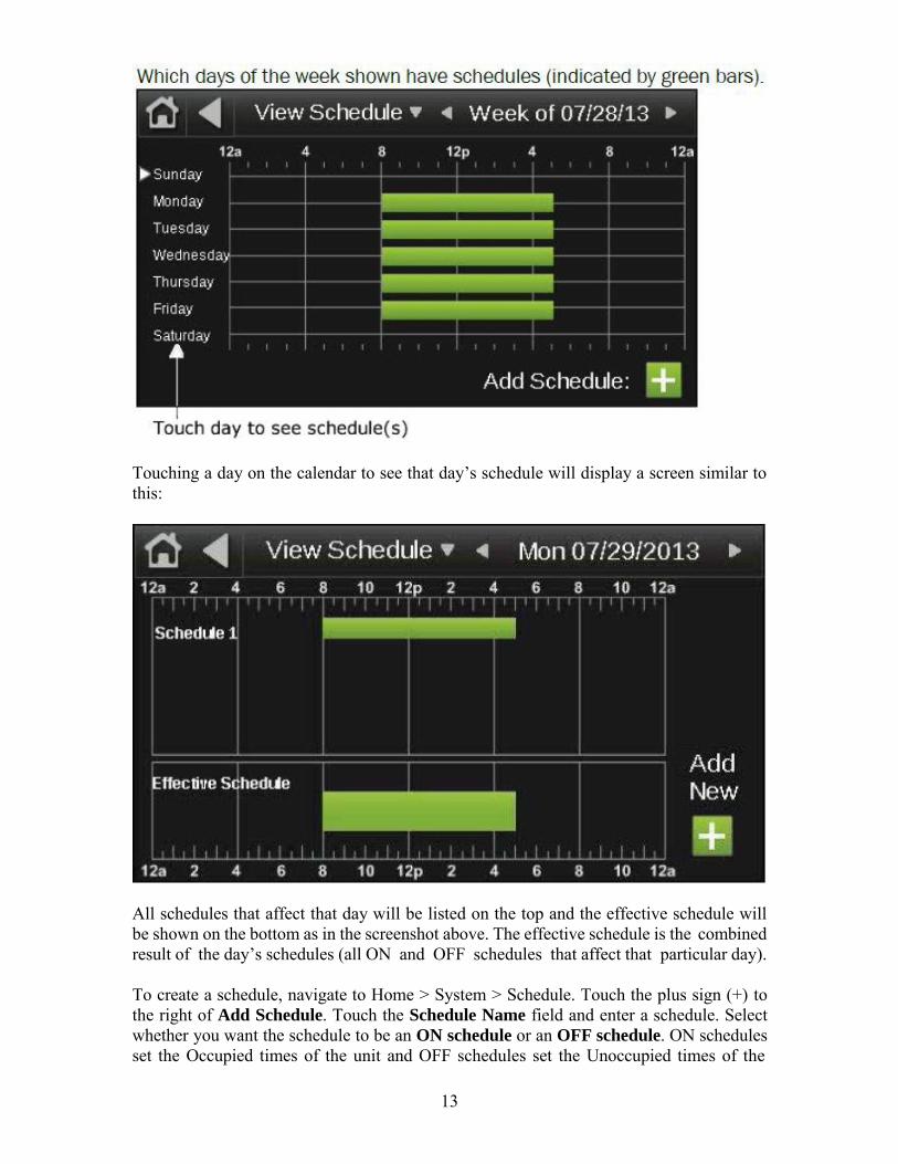
To view a schedule, navigate to Home > System > Schedule. Touch View Schedule and select Month View or Week View. Month View shows which days of the current month have schedules.
Week View shows which days of the current week have schedules. Touch a day to see the schedule for that day.
13
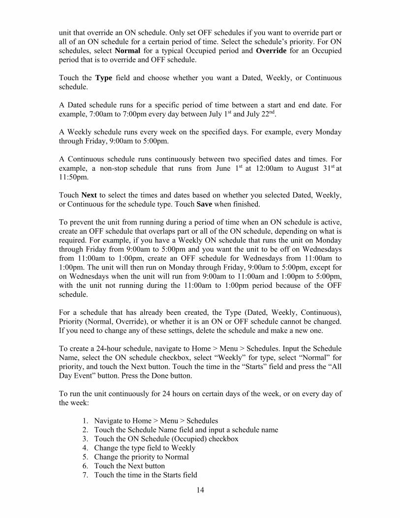
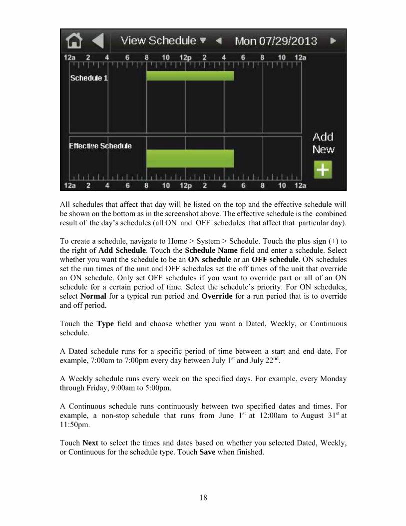
Touching a day on the calendar to see that day’s schedule will display a screen similar to this:
All schedules that affect that day will be listed on the top and the effective schedule will be shown on the bottom as in the screenshot above. The effective schedule is the combined result of the day’s schedules (all ON and OFF schedules that affect that particular day).
To create a schedule, navigate to Home > System > Schedule. Touch the plus sign (+) to the right of Add Schedule. Touch the Schedule Name field and enter a schedule. Select whether you want the schedule to be an ON schedule or an OFF schedule. ON schedules set the Occupied times of the unit and OFF schedules set the Unoccupied times of the
14
unit that override an ON schedule. Only set OFF schedules if you want to override part or all of an ON schedule for a certain period of time. Select the schedule’s priority. For ON schedules, select Normal for a typical Occupied period and Override for an Occupied period that is to override and OFF schedule.
Touch the Type field and choose whether you want a Dated, Weekly, or Continuous schedule.
A Dated schedule runs for a specific period of time between a start and end date. For example, 7:00am to 7:00pm every day between July 1st and July 22nd.
A Weekly schedule runs every week on the specified days. For example, every Monday through Friday, 9:00am to 5:00pm.
A Continuous schedule runs continuously between two specified dates and times. For example, a non-stop schedule that runs from June 1st at 12:00am to August 31st at 11:50pm.
Touch Next to select the times and dates based on whether you selected Dated, Weekly, or Continuous for the schedule type. Touch Save when finished.
To prevent the unit from running during a period of time when an ON schedule is active, create an OFF schedule that overlaps part or all of the ON schedule, depending on what is required. For example, if you have a Weekly ON schedule that runs the unit on Monday through Friday from 9:00am to 5:00pm and you want the unit to be off on Wednesdays from 11:00am to 1:00pm, create an OFF schedule for Wednesdays from 11:00am to 1:00pm. The unit will then run on Monday through Friday, 9:00am to 5:00pm, except for on Wednesdays when the unit will run from 9:00am to 11:00am and 1:00pm to 5:00pm, with the unit not running during the 11:00am to 1:00pm period because of the OFF schedule.
For a schedule that has already been created, the Type (Dated, Weekly, Continuous), Priority (Normal, Override), or whether it is an ON or OFF schedule cannot be changed. If you need to change any of these settings, delete the schedule and make a new one.
To create a 24-hour schedule, navigate to Home > Menu > Schedules. Input the Schedule Name, select the ON schedule checkbox, select “Weekly” for type, select “Normal” for priority, and touch the Next button. Touch the time in the “Starts” field and press the “All Day Event” button. Press the Done button.
To run the unit continuously for 24 hours on certain days of the week, or on every day of the week:
1. Navigate to Home > Menu > Schedules 2. Touch the Schedule Name field and input a schedule name 3. Touch the ON Schedule (Occupied) checkbox 4. Change the type field to Weekly 5. Change the priority to Normal 6. Touch the Next button 7. Touch the time in the Starts field
15
8. Touch the All Day Event button 9. Touch the Done button 10. Touch the desired Days buttons (M T W R F Sa Su) for the days you want the
unit to run 24 hours (some or all days may be selected) 11. If you only want this schedule to apply for a certain date range, touch the Yes
button to the right of the “Does this schedule have a date range?” statement, otherwise, touch No
12. Touch the Save button
Heating Night Setback The Heating Night Setback function automatically cycles the unit “on” if the room temperature falls below the Heating Setback temperature setpoint, and the unit is scheduled to be “off”. If the unit is scheduled to be “off” and the Heating Setback function turns the unit “on”, the unit will be cycled “off” once the room air temperature has risen 2° above the Heating Setback setpoint. The default for this setpoint is 55°F. To change the Heating Setback setpoint, navigate to Home > Menu > Setpoints, locate the Heating Setback setpoint and enter a new temperature. The allowable temperature range is 40°F - 130°F.
Cooling Night Setback
The Cooling Night Setback function automatically cycles the unit “on” if the room temperature rises above the Cooling Setback temperature setpoint and the unit is scheduled to be “off”. If the unit is scheduled to be “off” and the Cooling Setback function turns the unit “on”, the unit will be cycled off once the room air temperature has fallen 2° below the Cooling Setback setpoint. The default for this setpoint is 100°F. To change the Cooling Setback setpoint, navigate to Home > Menu > Setpoints, locate the Cooling Setback setpoint and enter a new temperature. The allowable temperature range is 40°F - 130°F.
Auxiliary Unit Enable
The Auxiliary Unit Enable function overrides all other Auto Mode functions and automatically cycles the unit into operation. This function is activated whenever a contact is closed between the appropriate terminals on the unit’s terminal strip located in the unit’s main control panel. Heating and cooling functions use the Night Setback Setpoints. See the Typical Wiring Schematic and Multiplexed Input sections of this manual for more information. This function can be used with a twist timer, toggle switch, door switch, exhaust fan interlock, or any other dry contact to override the time clock schedule.
Network Enable
The Network Enable function overrides all other Auto Mode functions and automatically cycles the unit into operation. This function is activated whenever the network enable BACnet parameter value is changed to on or true. Heating and cooling functions use the Occupied Setpoints.
MDT Controls Modulating discharge temperature (MDT) control is the most basic TracRite control for discharge temperature. The MDT control system includes a remote control panel equipped with 1 or 2 potentiometers, 3 or more pilot lights, and up to 2 switches.
16
UNIT OFF MODE Off Mode is the default unit operational mode. To place the unit in the Off Mode, rotate the “temperature setpoint” knob on the remote control panel counterclockwise to the stop. This will place the unit in the OFF mode and extinguish the “fan on” light. The OFF mode prevents the unit from starting.
UNIT MANUAL MODE
Manual Mode allows the unit to turn on. To place the unit in the Manual Mode, rotate the “temperature setpoint” knob on the remote control panel clockwise to the desired discharge air temperature setpoint. This will place the unit in the MANUAL mode and enable the fan and burner. See Heating/Ventilating/Cooling Modes and Energy Saving Modes of this manual for more information.
UNIT AUTO MODE
The MDT control does not support the time clock, night setback, or auxiliary unit enable functions.
MDT-Touch Controls The TracRite MDT-Touch (modulating discharge temperature) control system provides full information regarding unit operation and allows the user to adjust all operational parameters using the Equipment Touch panel. See the Menu Selection Tree for Equipment Touch section of this manual for more information about navigating the Equipment Touch menus.
UNIT OFF MODE
Off Mode is the default unit operational mode. To place the unit in Off Mode, navigate to Home > Menu > Modes. Change the Unit Enable parameter to “Off”. This will place the unit in the OFF mode. The OFF mode prevents the fan, burner, and cooling outputs from starting. This mode will override the Time Clock and Night Setback functions.
UNIT MANUAL MODE
Manual Mode allows the supply fan to turn on regardless of the Time Clock function. To place the unit in Manual Mode, navigate to Home > Menu > Modes. Change the Unit Enable parameter to “Manual”. This will place the unit in the MANUAL mode.
UNIT AUTO MODE
Auto Mode has three different functions that control the supply fan and unit operation. They are a time clock function and a signal from an external source to an auxiliary digital input. To place the unit in Auto Mode, navigate to Home > Menu > Modes. Change the Unit Enable parameter to “Auto”. This will place the unit in the AUTO mode. This activates the three Auto mode functions.
Scheduling Time Clock
The primary Auto Mode function is the Time Clock Schedule. The Time Clock function allows the user to set up the unit’s Scheduled On and Scheduled Off periods. There are two different schedules available: an ON schedule and an OFF schedule. The ON schedule sets the typical run times for the unit. The OFF schedule sets the off times for holidays and other shutdown periods. The TracRite DDC system has no preset on/off schedule.

17
To view a schedule, navigate to Home > System > Schedule. Touch View Schedule and select Month View or Week View. Month View shows which days of the current month have schedules.
Week View shows which days of the current week have schedules. Touch a day to see the schedule for that day.
Touching a day on the calendar to see that day’s schedule will display a screen similar to this:
18
All schedules that affect that day will be listed on the top and the effective schedule will be shown on the bottom as in the screenshot above. The effective schedule is the combined result of the day’s schedules (all ON and OFF schedules that affect that particular day).
To create a schedule, navigate to Home > System > Schedule. Touch the plus sign (+) to the right of Add Schedule. Touch the Schedule Name field and enter a schedule. Select whether you want the schedule to be an ON schedule or an OFF schedule. ON schedules set the run times of the unit and OFF schedules set the off times of the unit that override an ON schedule. Only set OFF schedules if you want to override part or all of an ON schedule for a certain period of time. Select the schedule’s priority. For ON schedules, select Normal for a typical run period and Override for a run period that is to override and off period.
Touch the Type field and choose whether you want a Dated, Weekly, or Continuous schedule.
A Dated schedule runs for a specific period of time between a start and end date. For example, 7:00am to 7:00pm every day between July 1st and July 22nd.
A Weekly schedule runs every week on the specified days. For example, every Monday through Friday, 9:00am to 5:00pm.
A Continuous schedule runs continuously between two specified dates and times. For example, a non-stop schedule that runs from June 1st at 12:00am to August 31st at 11:50pm.
Touch Next to select the times and dates based on whether you selected Dated, Weekly, or Continuous for the schedule type. Touch Save when finished.

19
To prevent the unit from running during a period of time when an ON schedule is active, create an OFF schedule that overlaps part or all of the ON schedule, depending on what is required. For example, if you have a Weekly ON schedule that runs the unit on Monday through Friday from 9:00am to 5:00pm and you want the unit to be off on Wednesdays from 11:00am to 1:00pm, create an OFF schedule for Wednesdays from 11:00am to 1:00pm. The unit will then run on Monday through Friday, 9:00am to 5:00pm, except for on Wednesdays when the unit will run from 9:00am to 11:00am and 1:00pm to 5:00pm, with the unit not running during the 11:00am to 1:00pm period because of the OFF schedule.
For a schedule that has already been created, the Type (Dated, Weekly, Continuous), Priority (Normal, Override), or whether it is an ON or OFF schedule cannot be changed. If you need to change any of these settings, delete the schedule and make a new one.
To run the unit continuously for 24 hours on certain days of the week, or on every day of the week:
1. Navigate to Home > Menu > Schedules 2. Touch the Schedule Name field and input a schedule name 3. Touch the ON Schedule (Occupied) checkbox 4. Change the type field to Weekly 5. Change the priority to Normal 6. Touch the Next button 7. Touch the time in the Starts field 8. Touch the All Day Event button 9. Touch the Done button 10. Touch the desired Days buttons (M T W R F Sa Su) for the days you want the
unit to run 24 hours (some or all days may be selected) 11. If you only want this schedule to apply for a certain date range, touch the Yes
button to the right of the “Does this schedule have a date range?” statement, otherwise, touch No
12. Touch the Save button
Auxiliary Unit Enable The Auxiliary Unit Enable function overrides all other Auto Mode functions and automatically cycles the unit into operation. This function is activated whenever a contact is closed between the appropriate terminals on the unit’s terminal strip located in the unit’s main control panel. See the Typical Wiring Schematic and Multiplexed Input sections of this manual for more information. This function can be used with a twist timer, toggle switch, door switch, exhaust fan interlock, or any other dry contact to override the time clock schedule.
Network Enable
The Network Enable function overrides all other Auto Mode functions and automatically cycles the unit into operation. This function is activated whenever the network enable BACnet parameter value is changed to on or true.

20
Heating/Ventilation/Cooling Operating Modes The TracRite DDC controller automatically switches between the heating, ventilating and cooling modes of operation. The previous sections described the Heating and Cooling Setback operation.
Heating Mode (MRT) Overview
In the Heating Mode of the MRT control system, the burner will modulate to maintain a constant room temperature and maintain the supply air temperature between the minimum and maximum heating discharge air temperature setpoints. A call for unit enable and a fan status signal must be present for the burner to turn on.
In order of lowest to greatest priority, the burner modulation parameters are maximum heating discharge air temperature, room temperature, minimum heating discharge air temperature, and equivalent temperature rise.
The burner is enabled if the outside air temperature is below the minimum heating discharge temperature setpoint or the room temperature is more than 2°F below the heating occupied setpoint.
The burner is disabled if the outside air temperature is more than 2°F above the minimum heating discharge air temperature setpoint and the room temperature is above the heating occupied setpoint, if an Energy Savings Mode is active, or if the Burner Hand alarm is active.
The burner is disabled if the unit enable potentiometer on the remote control panel is set to the Off position (turned all the way counter-clockwise).
Room Sensor Failsafe
TracRite units configured for MRT control will have a fixed discharge temperature of 70°F if the room temperature sensor is disconnected or otherwise fails to communicate with the unit control module.
Cooldown Period
For indirect fired units and electric heating units only, the fan will run for 3 minutes any time the burner or heater cycles on during the unoccupied period or if the burner or heater was running at the end of the occupied period to remove excess heat from the heat exchanger or heating coil.
Setpoints
To change the desired room temperature setpoint, rotate the temperature setpoint knob on the remote control panel clockwise to the desired temperature. The allowable temperature range is 55°F - 90°F.
General Burner Control
If the burner is enabled and the room setpoint is not yet satisfied, the unit will maintain the supply air temperature at the maximum heating discharge air temperature setpoint. As
21
the room temperature begins to rise, the unit will begin to limit the analog voltage output to the gas valve. This may limit the supply air temperature to prevent overheating the space.
Once the room temperature is satisfied, the analog voltage output limit may be overridden to allow the unit to maintain the supply air temperature above the minimum heating discharge air temperature setpoint if the outside air temperature is below the minimum heating discharge air temperature setpoint.
If the minimum and maximum discharge air temperature setpoints are set for the same temperature, the supply air temperature will be the same as the setpoint regardless of the room temperature setpoint or actual room temperature.
Energy Savings Mode 1 Mixing Box Recirculating Units
Energy Savings Mode 1 will automatically disable the burner if the mixed air temperature is equal to or greater than the minimum discharge air temperature setpoint, and the room air temperature is 5°F above the room air temperature setpoint. This function is intended to restrain the room temperature from rising uncontrollably in buildings with internal heat gain. The burner will remain disabled until the mixed air temperature falls 2°F below the mixed air temperature setpoint and the room temperature falls 2°F below the heating setpoint. In certain conditions it may be necessary to readjust the minimum discharge air or room temperature setpoint upward or adjust the outside/return air ratio to provide a warmer supply air temperature.
Energy Savings Mode 1 Non-Recirculating Units
Energy Savings Mode 1 will automatically disable the burner if the outside air temperature is equal to or greater than the minimum discharge air temperature setpoint, and the room air temperature is 5°F above the room air temperature setpoint. This function is intended to restrain the room temperature from rising uncontrollably in buildings with internal heat gain. The burner will remain disabled until the outside air temperature falls 2°F below the minimum discharge air temperature setpoint and the room temperature falls 2°F below the heating setpoint. In certain conditions it may be necessary to readjust the minimum discharge air or room temperature setpoint upward to provide a warmer supply air temperature.
Energy Savings Mode 2 Mixing Box Recirculating Direct-Fired Units
Energy Savings Mode 2 will automatically disable the burner if the burner’s minimum firing rate exceeds the maximum allowable equivalent temperature rise. This condition is unlikely to occur unless the burner’s minimum firing rate is misadjusted and set too high, or the inlet air opening is restricted.
Energy Savings Mode 3
Energy Savings Mode 3 will automatically disable the burner if the outside air temperature is above the Heating Economizer setpoint. This function is similar to an inlet duct thermostat. The burner will cycle back on if the supply air temperature drops 3°F below the Heating Economizer setpoint.

22
Recirculating Direct-Fired Heaters Using different controller software, the TracRite DDC system can accommodate three distinct types of recirculating direct-fired units: those that return air before the burner and employ a special airflow station, those that return air before the burner and do not employ a special airflow station, and those that recirculate air after the burner. Recirculating direct-fired units, like all direct-fired units, deliver all of their products of combustion directly to the heated air space. For this reason it is extremely important that the proper ventilation rate be maintained to dilute these emissions.
TracRite units, that recirculate air before the burner and employ an airflow measuring station, utilize a control scheme that measures air pressure to determine the ratio of outside air and return air. These units are listed by an independent third party testing agency and use the equivalent temperature rise control scheme to limit burner modulation. The TracRite system accurately measures the ratio of outside and return air, calculates the allowable equivalent temperature rise and automatically limits the burners firing rate. This insures the products of combustion, delivered to the space by the unit, are held at or below allowable OSHA thresholds. The outside air percentage is the driving parameter for this function. A greater percentage of outside air or dilution air enables the unit to generate a higher allowable equivalent temperature rise. The maximum allowable equivalent temperature rise for 20% outside air is 48.9°F. The maximum allowable equivalent temperature rise increases 1.22°F for each 1% increase in outside air.
TracRite units, that recirculate air before the burner and do not employ an airflow measuring station, utilize a control scheme that measures damper position to determine the percentage of return air. These units are not listed by an independent third party testing agency but do use the equivalent temperature rise control scheme to limit burner modulation. The maximum allowable equivalent temperature rise for 20% outside air is 48.9°F. The maximum allowable equivalent temperature rise increases 1.22°F for each 1% increase in outside air.
TracRite units that recirculate air after the burner are physically constrained to limit the percentage of return air. These constraints are meant to provide the proper dilution air. These units are not listed by an independent third party testing agency and do not use the equivalent temperature rise control scheme to limit burner modulation.
Heating Mode (MRT-Touch) Overview
In the Heating Mode of the MRT-Touch control system, the burner will modulate to maintain a constant room temperature and maintain the supply air temperature between the minimum and maximum heating discharge air temperature setpoints. A call for unit enable and a fan status signal must be present for the burner to turn on.
In order of lowest to greatest priority, the burner modulation parameters are maximum heating discharge air temperature, room temperature, minimum heating discharge air temperature, and equivalent temperature rise.
Room Sensor Failsafe
TracRite units configured for MRT-Touch controls will have a fixed discharge temperature of 70°F if the room temperature sensor is disconnected or otherwise fails to

23
communicate with the unit control module. When the room sensor fails to communicate with the controller, a room temperature of 0°F will display on the Equipment Touch.
Cooldown Period
For indirect fired units and electric heating units only, the fan will run for 3 minutes any time the burner or heater cycles on during the unoccupied period or if the burner or heater was running at the end of the occupied period to remove excess heat from the heat exchanger or heating coil.
Setpoints
Navigate to Home > Menu > Setpoints on the Equipment Touch to change heating setpoints.
Occupied Mode
The burner is enabled if the outside air temperature is below the minimum heating discharge temperature setpoint or the room temperature is more than 2°F below the heating occupied setpoint.
The burner is disabled if the outside air temperature is more than 2°F above the minimum heating discharge air temperature setpoint and the room temperature is above the heating occupied setpoint, if an Energy Savings Mode is active, or if the Burner Hand alarm is active.
Unoccupied / Night Setback Mode
The burner is enabled if the room temperature is below the heating night setback setpoint. The burner is disabled if the room temperature is 2°F above the heating night setback setpoint, if an Energy Savings Mode is active, or if the Burner Hand alarm is active.
Optimal Start
Optimal Start allows the fan and burner to start before the scheduled start time of the unit. This sequence automatically brings the room temperature up to the room setpoint by the time the occupied period starts to maximize occupant comfort.
Optimal Start uses the heating capacity, heating design temperature, outside air temperature, and room temperature data to calculate the optimal start time of the unit. The optimal start limit setpoint sets how soon before the scheduled start time the unit can start. The default value is 2 hours, so the unit will not be allowed to start to bring the room temperature up to the heating setpoint until 2 hours before the occupied period begins. However, the burner may still cycle on during the unoccupied period to maintain the heating unoccupied setpoint as required.
To prevent the unit from starting early to bring the room temperature up to the heating setpoint using Optimal Start, set the optimal start limit setpoint to 0 hours. This completely disabled the Optimal Start mode.
The unit “learns” the heating capacity of the space over time. The heating capacity represents how effective the unit is at heating the space in terms of degrees Fahrenheit per hour. The unit will slightly adjust the heating capacity every time the unit switches

24
from Unoccupied to Occupied mode based on how close the room temperature was to the room setpoint at the beginning of the occupied period.
Optimal Start uses heating and cooling design temperatures based on the location where the unit is installed to optimize performance using local climate data. Refer to Appendix H near the end of this manual for a list heating and cooling design temperatures for several cities. For cities and areas not listed in Appendix H, the heating and cooling design temperatures can usually be found on the internet.
The optimal start limit setpoint has a default value of 0 hours. Depending on the outside air temperature and room temperature, the unit and burner will be allowed to cycle on at any time within the two hours before the scheduled start time of the unit to bring the room temperature to the room setpoint when the occupied period begins.
Typically, lower outside air temperatures lead to earlier start times when Optimal Start is used in the heating mode. The room temperature will typically be lower during the unoccupied period when the outside air temperature is lower.
To maximize the energy savings that Optimal Start can provide, set the heating night setback setpoint lower to minimize cycling of the burner during the unoccupied period. The rate of heat lost to the outside environment from the space increases as the temperature differential between outside and the space increases. Keeping the room temperature as low as possible during the unoccupied period allows the unit to only turn the burner on to maintain the lower heating night setback setpoint (if necessary), or to bring the space up to the heating occupied setpoint by the time the occupied period begins.
Ideally, the heating night setback setpoint would be set low enough that the space temperature never reaches it so the burner only cycles on near the end of the unoccupied period to bring the room temperature up to the heating occupied setpoint. However, if the optimal start limit setpoint is not high enough, the unit will not be permitted to start as early as it needs to. For example, if the optimal start limit setpoint is set to 2 hours and the unit needs to start 3 hours early to bring the room temperature up to the heating occupied setpoint by the time the occupied period begins, it will be unable to do so and will instead start as soon as the optimal start limit setpoint allows, which in this case would be 2 hours before the beginning of the occupied period.
General Burner Control
If the burner is enabled and the room setpoint is not yet satisfied, the unit will maintain the supply air temperature at the maximum heating discharge air temperature setpoint. As the room temperature begins to rise, the unit will begin to limit the analog voltage output to the gas valve. This may limit the supply air temperature to prevent overheating the space.
Once the room temperature is satisfied, the analog voltage output limit may be overridden to allow the unit to maintain the supply air temperature above the minimum heating discharge air temperature setpoint if the outside air temperature is below the minimum heating discharge air temperature setpoint.

25
If the minimum and maximum discharge air temperature setpoints are set for the same temperature, the supply air temperature will be the same as the setpoint regardless of the room temperature setpoint or actual room temperature.
Energy Savings Mode 1 Mixing Box Recirculating Units
Energy Savings Mode 1 will automatically disable the burner if the mixed air temperature is equal to or greater than the minimum discharge air temperature setpoint, and the room air temperature is 5°F above the room air temperature setpoint. This function is intended to restrain the room temperature from rising uncontrollably in buildings with internal heat gain. The burner will remain disabled until the mixed air temperature falls 2°F below the mixed air temperature setpoint and the room temperature falls 2°F below the heating setpoint. In certain conditions it may be necessary to readjust the minimum discharge air or room temperature setpoint upward or adjust the outside/return air ratio to provide a warmer supply air temperature.
Energy Savings Mode 1 Non-Recirculating Units
Energy Savings Mode 1 will automatically disable the burner if the outside air temperature is equal to or greater than the minimum discharge air temperature setpoint, and the room air temperature is 5°F above the room air temperature setpoint. This function is intended to restrain the room temperature from rising uncontrollably in buildings with internal heat gain. The burner will remain disabled until the outside air temperature falls 2°F below the minimum discharge air temperature setpoint and the room temperature falls 2°F below the heating setpoint. In certain conditions it may be necessary to readjust the minimum discharge air or room temperature setpoint upward to provide a warmer supply air temperature.
Energy Savings Mode 2 Mixing Box Recirculating Direct-Fired Units
Energy Savings Mode 2 will automatically disable the burner if the burner’s minimum firing rate exceeds the maximum allowable equivalent temperature rise. This condition is unlikely to occur unless the burner’s minimum firing rate is misadjusted and set too high, or the inlet air opening is restricted.
Energy Savings Mode 3
Energy Savings Mode 3 will automatically disable the burner if the outside air temperature is above the Heating Economizer setpoint. This function is similar to an inlet duct thermostat. The burner will cycle back on if the supply air temperature drops 3°F below the Heating Economizer setpoint.
Recirculating Direct-Fired Heaters
Using different controller software, the TracRite DDC system can accommodate three distinct types of recirculating direct-fired units: those that return air before the burner and employ a special airflow station, those that return air before the burner and do not employ a special airflow station, and those that recirculate air after the burner. Recirculating direct-fired units, like all direct-fired units, deliver all of their products of combustion directly to the heated air space. For this reason it is extremely important that the proper ventilation rate be maintained to dilute these emissions.
TracRite units, that recirculate air before the burner and employ an airflow measuring station, utilize a control scheme that measures air pressure to determine the ratio of outside air and return air. These units are listed by an independent third party testing

26
agency and use the equivalent temperature rise control scheme to limit burner modulation. The TracRite system accurately measures the ratio of outside and return air, calculates the allowable equivalent temperature rise and automatically limits the burners firing rate. This insures the products of combustion, delivered to the space by the unit, are held at or below allowable OSHA thresholds. The outside air percentage is the driving parameter for this function. A greater percentage of outside air or dilution air enables the unit to generate a higher allowable equivalent temperature rise. The maximum allowable equivalent temperature rise for 20% outside air is 48.9°F. The maximum allowable equivalent temperature rise increases 1.22°F for each 1% increase in outside air.
TracRite units, that recirculate air before the burner and do not employ an airflow measuring station, utilize a control scheme that measures damper position to determine the percentage of return air. These units are not listed by an independent third party testing agency but do use the equivalent temperature rise control scheme to limit burner modulation. The maximum allowable equivalent temperature rise for 20% outside air is 48.9°F. The maximum allowable equivalent temperature rise increases 1.22°F for each 1% increase in outside air.
TracRite units that recirculate air after the burner are physically constrained to limit the percentage of return air. These constraints are meant to provide the proper dilution air. These units are not listed by an independent third party testing agency and do not use the equivalent temperature rise control scheme to limit burner modulation.
Heating Mode (MDT) Overview
In the Heating Mode of the MDT control system, the burner will modulate to maintain a constant supply air temperature. A call for unit enable and a fan status signal must be present for the burner to turn on.
In order of lowest to greatest priority, the burner modulation parameters are supply air temperature and equivalent temperature rise.
The burner is enabled if the outside air temperature is more than 2°F below the heating/cooling changeover setpoint.
The burner is disabled if the outside air temperature is above the heating/cooling changeover setpoint.
The burner is disabled if the unit enable potentiometer on the remote control panel is set to the Off position (turned all the way counter-clockwise).
Setpoints
To change the desired heating discharge temperature setpoint of an MDT control system, rotate the temperature setpoint knob on the remote control panel clockwise to the desired temperature. The allowable temperature range is 55°F - 90°F.

27
General Burner Control If the burner is enabled, the unit will maintain the supply air temperature at the discharge air temperature setpoint.
Energy Savings Mode 2 Mixing Box Recirculating Direct-Fired Units
Energy Savings Mode 2 will automatically disable the burner if the burner’s minimum firing rate exceeds the maximum allowable equivalent temperature rise. This condition is unlikely to occur unless the burner’s minimum firing rate is misadjusted and set too high, or the inlet air opening is restricted.
Energy Savings Mode 3
Energy Savings Mode 3 will automatically disable the burner if the outside air temperature is above the Heating Economizer setpoint. This function is similar to an inlet duct thermostat. The burner will cycle back on if the supply air temperature drops 3°F below the Heating Economizer setpoint.
Recirculating Direct-Fired Heaters
Using different controller software, the TracRite DDC system can accommodate three distinct types of recirculating direct-fired units: those that return air before the burner and employ a special airflow station, those that return air before the burner and do not employ a special airflow station, and those that recirculate air after the burner. Recirculating direct-fired units, like all direct-fired units, deliver all of their products of combustion directly to the heated air space. For this reason it is extremely important that the proper ventilation rate be maintained to dilute these emissions.
TracRite units, that recirculate air before the burner and employ an airflow measuring station, utilize a control scheme that measures air pressure to determine the ratio of outside air and return air. These units are listed by an independent third party testing agency and use the equivalent temperature rise control scheme to limit burner modulation. The TracRite system accurately measures the ratio of outside and return air, calculates the allowable equivalent temperature rise and automatically limits the burners firing rate. This insures the products of combustion, delivered to the space by the unit, are held at or below allowable OSHA thresholds. The outside air percentage is the driving parameter for this function. A greater percentage of outside air or dilution air enables the unit to generate a higher allowable equivalent temperature rise. The maximum allowable equivalent temperature rise for 20% outside air is 48.9°F. The maximum allowable equivalent temperature rise increases 1.22°F for each 1% increase in outside air.
TracRite units, that recirculate air before the burner and do not employ an airflow measuring station, utilize a control scheme that measures damper position to determine the percentage of return air. These units are not listed by an independent third party testing agency but do use the equivalent temperature rise control scheme to limit burner modulation. The maximum allowable equivalent temperature rise for 20% outside air is 48.9°F. The maximum allowable equivalent temperature rise increases 1.22°F for each 1% increase in outside air.
For TracRite units that recirculate air before the burner and use the MDT control, the maximum burner firing rate is limited by the discharge setpoint or the maximum allowable equivalent temperature rise, whichever is less.
28
TracRite units that recirculate air after the burner are physically constrained to limit the percentage of return air. These constraints are meant to provide the proper dilution air. These units are not listed by an independent third party testing agency and do not use the equivalent temperature rise control scheme to limit burner modulation.
Heating Mode (MDT-Touch) Overview
In the Heating Mode of the MDT-Touch control system, the burner will modulate to maintain a constant supply air temperature. A call for unit enable and a fan status signal must be present for the burner to turn on.
In order of lowest to greatest priority, the burner modulation parameters are supply air temperature and equivalent temperature rise.
Setpoints
Navigate to Home > Menu > Setpoints on the Equipment Touch to change setpoints.
Scheduled On Mode Scheduled On mode refers to any time the unit is running based on an ON schedule.
The burner is enabled if the outside air temperature is more than 2°F below the heating/cooling changeover setpoint in Scheduled On mode.
The burner is disabled if the outside air temperature is above the heating/cooling changeover setpoint in Scheduled On mode.
Scheduled Off Mode
Scheduled Off mode refers to any time the unit is outside of the time ranges of any ON schedules. The burner is disabled in Scheduled Off mode.
General Burner Control
If the burner is enabled, the unit will maintain the supply air temperature at the discharge air temperature setpoint.
Energy Savings Mode 2 Mixing Box Recirculating Direct-Fired Units
Energy Savings Mode 2 will automatically disable the burner if the burner’s minimum firing rate exceeds the maximum allowable equivalent temperature rise. This condition is unlikely to occur unless the burner’s minimum firing rate is misadjusted and set too high, or the inlet air opening is restricted.
Energy Savings Mode 3
Energy Savings Mode 3 will automatically disable the burner if the outside air temperature is above the Heating Economizer setpoint. This function is similar to an inlet duct thermostat. The burner will cycle back on if the supply air temperature drops 3°F below the Heating Economizer setpoint.
Recirculating Direct-Fired Heaters
Using different controller software, the TracRite DDC system can accommodate three distinct types of recirculating direct-fired units: those that return air before the burner and

29
employ a special airflow station, those that return air before the burner and do not employ a special airflow station, and those that recirculate air after the burner. Recirculating direct-fired units, like all direct-fired units, deliver all of their products of combustion directly to the heated air space. For this reason it is extremely important that the proper ventilation rate be maintained to dilute these emissions.
TracRite units, that recirculate air before the burner and employ an airflow measuring station, utilize a control scheme that measures air pressure to determine the ratio of outside air and return air. These units are listed by an independent third party testing agency and use the equivalent temperature rise control scheme to limit burner modulation. The TracRite system accurately measures the ratio of outside and return air, calculates the allowable equivalent temperature rise and automatically limits the burners firing rate. This insures the products of combustion, delivered to the space by the unit, are held at or below allowable OSHA thresholds. The outside air percentage is the driving parameter for this function. A greater percentage of outside air or dilution air enables the unit to generate a higher allowable equivalent temperature rise. The maximum allowable equivalent temperature rise for 20% outside air is 48.9°F. The maximum allowable equivalent temperature rise increases 1.22°F for each 1% increase in outside air.
TracRite units, that recirculate air before the burner and do not employ an airflow measuring station, utilize a control scheme that measures damper position to determine the percentage of return air. These units are not listed by an independent third party testing agency but do use the equivalent temperature rise control scheme to limit burner modulation. The maximum allowable equivalent temperature rise for 20% outside air is 48.9°F. The maximum allowable equivalent temperature rise increases 1.22°F for each 1% increase in outside air.
For TracRite units that recirculate air before the burner and use the MDT-Touch control, the maximum burner firing rate is limited by the discharge setpoint or the maximum allowable equivalent temperature rise, whichever is less.
TracRite units that recirculate air after the burner are physically constrained to limit the percentage of return air. These constraints are meant to provide the proper dilution air. These units are not listed by an independent third party testing agency and do not use the equivalent temperature rise control scheme to limit burner modulation.
Ventilation Mode Ventilation Mode occurs when the fan is running but the unit is not providing heating or cooling.
The ventilation mode is dependent on the room (MRT or MRT-Touch) or outside air (MDT or MDT-Touch) temperature. The heating/ventilation/cooling operation is demonstrated below. The dotted line in the middle of the diagram represents the change between room temperature rise and room temperature fall. Select a point on the heavy line in the diagrams on the following pages to determine the mode of operation.

30
Unoccupied Example: (MRT-Touch only): Start at point “A”. The unit is off, because neither heating nor cooling is required, and the room temperature is rising. Follow the dashed line upward. If the room temperature rises to the cooling setpoint, the fan and cooling will be enabled, and the unit will be in the cooling mode. Follow the solid line clockwise. Once the room temperature has fallen to a temperature that is 2°F below the cooling setpoint, the cooling and fan will be disabled. Follow the dashed line downward. If the room temperature falls to the heating setpoint, the fan and heating will be enabled, and the unit will be in the heating mode. Continue following the solid line in a clockwise direction to the heating setpoint. Once the room temperature rises to a temperature that is 2°F above the heating setpoint, the heating and fan will be disabled.
Cooling mode
T E M P E R A T U R E
R I S E
Cooling mode
Cooling mode
Heating mode
A
cooling SPcooling enable
-2°F of cooling SPcooling disable
+2°F of heating SPheating disable
heating SPheating enable
T E M P E R A T U R E
F A L L
Fan off
Fan off
Heating mode
Heating mode

31
Occupied Example (MRT-Touch only): Start at point “A”. The unit is in the ventilation mode and the room or outside air temperature is rising. Follow the dashed line upward. If the room or outside air temperature rises to a temperature that is 2°F over the cooling setpoint, the cooling will be enabled, and the unit will be in the cooling mode. Follow the solid line clockwise. Once the room or outside air temperature has fallen to the cooling setpoint, the cooling mode will be disabled, and the unit will be in the ventilation mode. Follow the dashed line downward. If the room or outside air temperature falls to a temperature that is 2°F below the heating setpoint, the heating will be enabled, and the unit will be in the heating mode. Continue following the solid line in a clockwise direction to the heating setpoint. Once the room or outside air temperature rises to the heating setpoint, the heating mode will be disabled, and the unit will be in the ventilation mode.
Cooling mode
T E M P E R A T U R E
R I S E
Cooling mode
Cooling mode
Heating mode
A cooling SP
+2°F of cooling SPcooling enable
-2°F of heating SPheating enable
heating SP
T E M P E R A T U R E
F A L L
Ventilation mode
Ventilation mode
Heating mode
Heating mode

32
Cooling Mode (MRT) Overview
In the Cooling Mode of the MRT control system, the cooling outputs will cycle to maintain a constant room temperature and maintain the supply air temperature between the minimum and maximum cooling discharge air temperature setpoints. A call for unit enable and a fan status signal must be present for the cooling outputs to turn on.
In order of lowest to greatest priority, the cooling cycling parameters are minimum cooling discharge air temperature, room temperature, and maximum cooling discharge air temperature.
Cooling is enabled if the outside air temperature is above the maximum cooling discharge temperature setpoint or the room temperature is more than 2°F above the cooling occupied setpoint.
Cooling is disabled if the outside air temperature is more than 2°F below the maximum cooling discharge air temperature setpoint and the room temperature is below the cooling occupied setpoint or if an Energy Savings Mode is active.
Cooling is disabled if the unit enable potentiometer on the remote control panel is set to the Off position (turned all the way counter-clockwise).
Room Sensor Failsafe
TracRite units configured for MRT control will have a fixed discharge temperature of 70°F if the room temperature sensor is disconnected or otherwise fails to communicate with the unit control module.
Setpoints
To change the desired room temperature setpoint of an MRT control system, rotate the temperature setpoint knob on the remote control panel clockwise to the desired temperature. The allowable temperature range is 55°F - 90°F.
General Cooling Control
If cooling is enabled and the room setpoint is not yet satisfied, the unit will maintain the supply air temperature at the minimum cooling discharge air temperature setpoint. As the room temperature begins to fall, the unit will begin to limit the calculated cooling demand. This may limit the supply air temperature by cycling off the cooling output(s) to prevent overcooling the space.
Once the room temperature is satisfied, the calculated cooling demand may be overridden to allow the unit to maintain the supply air temperature below the maximum cooling discharge air temperature setpoint if the outside air temperature is above the maximum cooling discharge air temperature setpoint.
If the minimum and maximum discharge air temperature setpoints are set for the same temperature, the supply air temperature will be the same as the setpoint regardless of the room temperature setpoint or actual room temperature.
The cooling outputs are protected by an anti-cycle timer which has a 3 minute off / 3 minute on delay.

33
Two Stage Cooling Cycling Sequence This section describes the cycling sequence of the cooling outputs for units capable of controlling two stages of cooling. These units use the I/O Zone 583 controller.
The cooling demand is expressed as a percentage from 0 to 100 and is calculated by a PID loop. If the cooling demand is greater than 25%, stage 1 cooling is enabled. If the cooling demand is greater than 85% for three minutes and a call for stage 1 cooling is present, stage 2 cooling is enabled.
Stage 2 cooling is then disabled when the cooling demand falls below 65% and stage 1 cooling is then disabled when the cooling demand falls below 5%.
Four Stage Cooling Cycling Sequence
The MRT control system does not support the four stage cooling cycling sequence. This sequence requires the I/O Flex 6126 controller which does not support the potentiometer inputs required for an MRT control system. Units that require four stages of cooling must use the MRT-Touch or MDT-Touch control system.
Energy Savings Mode 4 Energy Savings Mode 4 will automatically disable the cooling outputs if the outside air temperature is below the Cooling Economizer setpoint. This function is similar to an inlet duct thermostat. The cooling will cycle back on if the outside air temperature rises 3°F above the Cooling Economizer setpoint.
Cooling Mode (MRT-Touch) Overview
In the Cooling Mode of the MRT-Touch control system, the cooling outputs will cycle to maintain a constant room temperature and maintain the supply air temperature between the minimum and maximum cooling discharge air temperature setpoints. A call for unit enable and a fan status signal must be present for the cooling outputs to turn on.
In order of lowest to greatest priority, the cooling cycling parameters are minimum cooling discharge air temperature, room temperature, and maximum cooling discharge air temperature.
Room Sensor Failsafe
TracRite units configured for MRT-Touch controls will have a fixed discharge temperature of 70°F if the room temperature sensor is disconnected or otherwise fails to communicate with the unit control module. When the room sensor fails to communicate with the controller, a room temperature of 0°F will display on the Equipment Touch.
Setpoints
Navigate to Home > Menu > Setpoints on the Equipment Touch to change cooling setpoints.

34
Occupied Mode Cooling is enabled if the outside air temperature is above the maximum cooling discharge temperature setpoint or the room temperature is more than 2°F above the cooling occupied setpoint.
Cooling is disabled if the outside air temperature is more than 2°F below the maximum cooling discharge air temperature setpoint and the room temperature is below the cooling occupied setpoint or if an Energy Savings Mode is active.
Unoccupied / Night Setback Mode
Cooling is enabled if the room temperature is above the cooling night setback setpoint. Cooling is disabled if the room temperature is 2°F below the cooling night setback setpoint or if an Energy Savings Mode is active.
Optimal Start
Optimal Start allows the fan and cooling outputs to start before the scheduled start time of the unit. This sequence automatically brings the room temperature down to the room setpoint by the time the occupied period starts to maximize occupant comfort.
Optimal Start uses the cooling capacity, cooling design temperature, outside air temperature, and room temperature data to calculate the optimal start time of the unit. The optimal start limit setpoint sets how soon before the scheduled start time the unit can start. The default value is 2 hours, so the unit will not be allowed to start to bring the room temperature down to the cooling setpoint until 2 hours before the occupied period begins. However, the cooling outputs may still cycle on during the unoccupied period to maintain the cooling unoccupied setpoint as required.
To prevent the unit from starting early to bring the room temperature down to the cooling setpoint using Optimal Start, set the optimal start limit setpoint to 0 hours. This completely disables the Optimal Start mode.
The unit “learns” the cooling capacity of the space over time. The cooling capacity represents how effective the unit is at cooling the space in terms of degrees Fahrenheit per hour. The unit will slightly adjust the cooling capacity every time the unit switches from Unoccupied to Occupied mode based on how close the room temperature was to the room setpoint at the beginning of the occupied period.
Optimal Start uses heating and cooling design temperatures based on the location where the unit is installed to optimize performance using local climate data. Refer to Appendix H near the end of this manual for a list heating and cooling design temperatures for several cities. For cities and areas not listed in Appendix H, the heating and cooling design temperatures can usually be found on the internet.
The optimal start limit setpoint has a default value of 2 hours. Depending on the outside air temperature and room temperature, the unit and cooling outputs will be allowed to cycle on at any time within the two hours before the scheduled start time of the unit to bring the room temperature to the room setpoint when the occupied period begins.

35
Typically, higher outside air temperatures lead to earlier start times when Optimal Start is used in the cooling mode. The room temperature will typically be higher during the unoccupied period when the outside air temperature is higher.
To maximize the energy savings that Optimal Start can provide, set the cooling night setback setpoint higher to minimize cycling of the cooling outputs during the unoccupied period. The rate of heat gained by the space from the outside environment increases as the temperature differential between outside and the space increases. Keeping the room temperature as high as possible during the unoccupied period allows the unit to only turn the cooling outputs on to maintain the higher cooling night setback setpoint (if necessary), or to bring the space down to the cooling occupied setpoint by the time the occupied period begins.
Ideally, the cooling night setback setpoint would be set high enough that the space temperature never reaches it so the cooling outputs only cycle on near the end of the unoccupied period to bring the room temperature down to the cooling occupied setpoint. However, if the optimal start limit setpoint is not high enough, the unit will not be permitted to start as early as it needs to. For example, if the optimal start limit setpoint is set to 2 hours and the unit needs to start 3 hours early to bring the room temperature down to the cooling occupied setpoint by the time the occupied period begins, it will be unable to do so and will instead start as soon as the optimal start limit setpoint allows, which in this case would be 2 hours before the beginning of the occupied period.
General Cooling Control
If cooling is enabled and the room setpoint is not yet satisfied, the unit will maintain the supply air temperature at the minimum cooling discharge air temperature setpoint. As the room temperature begins to fall, the unit will begin to limit the calculated cooling demand. This may limit the supply air temperature by cycling off the cooling output(s) to prevent overcooling the space.
Once the room temperature is satisfied, the calculated cooling demand may be overridden to allow the unit to maintain the supply air temperature below the maximum cooling discharge air temperature setpoint if the outside air temperature is above the maximum cooling discharge air temperature setpoint.
If the minimum and maximum discharge air temperature setpoints are set for the same temperature, the supply air temperature will be the same as the setpoint regardless of the room temperature setpoint or actual room temperature.
The cooling outputs are protected by an anti-cycle timer which has a 3 minute off / 3 minute on delay.
Two Stage Cooling Cycling Sequence
This section describes the cycling sequence of the cooling outputs for units capable of controlling two stages of cooling. These units use the I/O Zone 583 controller.
The cooling demand is expressed as a percentage from 0 to 100 and is calculated by a PID loop. If the cooling demand is greater than 25%, stage 1 cooling is enabled. If the cooling demand is greater than 85% for three minutes and a call for stage 1 cooling is present, stage 2 cooling is enabled.

36
Stage 2 cooling is then disabled when the cooling demand falls below 65% and stage 1 cooling is then disabled when the cooling demand falls below 5%.
Four Stage Cooling Cycling Sequence
This section describes the cycling sequence of the cooling outputs for units capable of controlling four stages of cooling. These units use the I/O Flex 6126 controller.
The cooling demand is expressed as a percentage from 0 to 100 and is calculated by a PID loop. If the cooling demand is greater than 25%, stage 1 cooling is enabled. If the cooling demand is greater than 50% for three minutes and a call for stage 1 cooling is present, stage 2 cooling is enabled. If the cooling demand is greater than 75% for three minutes and a call for stage 2 cooling is present, stage 3 cooling is enabled. If the cooling demand is greater than 95% for three minutes and a call for stage 3 cooling is present, stage 4 cooling is enabled.
Stage 4 cooling is then disabled when the cooling demand falls below 80%. Stage 3 cooling is then disabled when the cooling demand falls below 55%. Stage 2 cooling is then disabled when the cooling demand falls below 30%. Stage 1 cooling is then disabled when the cooling demand falls below 5%.
Energy Savings Mode 4
Energy Savings Mode 4 will automatically disable the cooling outputs if the outside air temperature is below the Cooling Economizer setpoint. This function is similar to an inlet duct thermostat. The cooling will cycle back on if the outside air temperature rises 3°F above the Cooling Economizer setpoint.
Cooling Mode (MDT) Overview
In the Cooling Mode of the MDT control system, the cooling outputs will cycle to maintain a constant supply air temperature. A call for unit enable and a fan status signal must be present for the cooling outputs to turn on.
Cooling is enabled if the outside air temperature is more than 2°F above the heating/cooling changeover setpoint.
Cooling is disabled if the outside air temperature is below the heating/cooling changeover setpoint..
Cooling is disabled if the unit enable potentiometer on the remote control panel is set to the Off position (turned all the way counter-clockwise).
Setpoints
To change the desired cooling discharge temperature of an MDT control system, rotate the temperature setpoint knob on the remote control panel clockwise to the desired temperature. The allowable temperature range is 55°F - 90°F.

37
General Cooling Control If cooling is enabled, the unit will maintain the supply air temperature at the discharge air temperature setpoint.
Two Stage Cooling Cycling Sequence
This section describes the cycling sequence of the cooling outputs for units capable of controlling two stages of cooling. These units use the I/O Zone 583 controller.
The cooling demand is expressed as a percentage from 0 to 100 and is calculated by a PID loop. If the cooling demand is greater than 25%, stage 1 cooling is enabled. If the cooling demand is greater than 85% for three minutes and a call for stage 1 cooling is present, stage 2 cooling is enabled.
Stage 2 cooling is then disabled when the cooling demand falls below 65% and stage 1 cooling is then disabled when the cooling demand falls below 5%.
Four Stage Cooling Cycling Sequence
The MDT control system does not support the four stage cooling cycling sequence. This sequence requires the I/O Flex 6126 controller which does not support the potentiometer inputs required for an MDT control system. Units that require four stages of cooling must use the MRT-Touch or MDT-Touch control system.
Energy Savings Mode 4 Energy Savings Mode 4 will automatically disable the cooling outputs if the outside air temperature is below the Cooling Economizer setpoint. This function is similar to an inlet duct thermostat. The cooling will cycle back on if the outside air temperature rises 3°F above the Cooling Economizer setpoint.
Cooling Mode (MDT-Touch) Overview
In the Cooling Mode of the MDT-Touch control system, the cooling outputs will cycle to maintain a constant supply air temperature. A call for unit enable and a fan status signal must be present for the cooling outputs to turn on.
Setpoints
Navigate to Home > Menu > Setpoints on the Equipment Touch to change setpoints.
Scheduled On Mode Scheduled On mode refers to any time the unit is running based on an ON schedule.
Cooling is enabled if the outside air temperature is more than 2°F above the heating/cooling changeover setpoint in Scheduled On mode.
Cooling is disabled if the outside air temperature is below the heating/cooling changeover setpoint in Scheduled On mode.
38
Scheduled Off Mode Scheduled Off mode refers to any time the unit is outside of the time ranges of any ON schedules. Cooling is disabled in Scheduled Off mode.
General Cooling Control
If cooling is enabled, the unit will maintain the supply air temperature at the discharge air temperature setpoint.
Two Stage Cooling Cycling Sequence
This section describes the cycling sequence of the cooling outputs for units capable of controlling two stages of cooling. These units use the I/O Zone 583 controller.
The cooling demand is expressed as a percentage from 0 to 100 and is calculated by a PID loop. If the cooling demand is greater than 25%, stage 1 cooling is enabled. If the cooling demand is greater than 85% for three minutes and a call for stage 1 cooling is present, stage 2 cooling is enabled.
Stage 2 cooling is then disabled when the cooling demand falls below 65% and stage 1 cooling is then disabled when the cooling demand falls below 5%.
Four Stage Cooling Cycling Sequence
This section describes the cycling sequence of the cooling outputs for units capable of controlling four stages of cooling. These units use the I/O Flex 6126 controller.
The cooling demand is expressed as a percentage from 0 to 100 and is calculated by a PID loop. If the cooling demand is greater than 25%, stage 1 cooling is enabled. If the cooling demand is greater than 50% for three minutes and a call for stage 1 cooling is present, stage 2 cooling is enabled. If the cooling demand is greater than 75% for three minutes and a call for stage 2 cooling is present, stage 3 cooling is enabled. If the cooling demand is greater than 95% for three minutes and a call for stage 3 cooling is present, stage 4 cooling is enabled.
Stage 4 cooling is then disabled when the cooling demand falls below 80%. Stage 3 cooling is then disabled when the cooling demand falls below 55%. Stage 2 cooling is then disabled when the cooling demand falls below 30%. Stage 1 cooling is then disabled when the cooling demand falls below 5%.
Energy Savings Mode 4
Energy Savings Mode 4 will automatically disable the cooling outputs if the outside air temperature is below the Cooling Economizer setpoint. This function is similar to an inlet duct thermostat. The cooling will cycle back on if the outside air temperature rises 3°F above the Cooling Economizer setpoint.

39
Damper Control Modes Overview There are four different modes that control the unit damper operation: Manual, Mixed Air Temperature, Building Pressure, and 100% Outside Air. Not all damper modes are available on all units.
To change the Damper Mode (except for 100% Outside Air mode), navigate to Home > Menu > Modes. Change the Damper Mode parameter to the desired Damper Mode.
Outside air dampers will remain in the fully closed position and return air dampers will remain in the fully open position any time the fan is not running. A fan status signal must be present for the dampers to operate in manual, mixed air, or building pressure mode. The 100% outside air mode will function even if the fan is not running, driving the outside air dampers fully open and the return air dampers fully closed. If the fan is running, the 100% outside air mode will override the manual, mixed air, and building pressure modes.
Manual mode is the default damper operation mode for all units except for units with 75/25 dampers. The default damper operation mode for 75/25 units is the building pressure mode.
Minimum Ventilation
Changing the Minimum Ventilation setpoint requires the use of an Equipment Touch or PC. The Minimum Ventilation function defines the minimum outside air percentage and automatically prevents the dampers from modulating below this point. This function applies to heating, cooling, and ventilation modes.
If the unit served by this control is a direct-fired heater that recirculates air before the burner, and is operating in the heating mode, the unit will automatically keep the minimum outside air at 20%. If the outside air drops below 20%, the burner will cycle off.
To specify the Minimum Ventilation, navigate to Home > Menu > Setpoints and set the Minimum Ventilation setpoint to a percentage corresponding to the minimum percentage of outside air desired. The allowable range is 0% - 100% outside air. By physical design, direct-fired heaters that recirculate air after the burner supply a minimum of 25% outside air.
Manual Mode Manual Mode sets the outside air damper to a fixed position on units without a return airflow station.
On units with a return airflow station, a PID loop controls the outside air damper position so the position of the dampers can be variable. The damper position may change as the return air pressure changes to maintain a fixed percentage of outside air according to the Manual Ventilation setpoint. A PID loop with a 2% deadband prevents the dampers from

40
changing position in the manual mode unless the calculated percentage of outside air is more than 2% away from setpoint.
If the unit served by this control is a direct-fired heater that recirculates air after the burner, the unit is designed to provide a minimum of 25% outside air.
If the unit served by this control is a direct-fired heater that recirculates air before the burner, and is operating in the heating mode, the unit will automatically keep the minimum outside air at 20%. If the outside air drops below 20%, the burner will cycle off. See Minimum Ventilation.
MRT and MDT Controls
To place the damper operation in Manual Mode on an MDT or MRT control system be sure the appropriate terminals in the unit control panel are not shorted. See the Typical Wiring Schematic and Multiplexed Input sections of this manual for more information. Rotate the damper control knob on the remote control panel to the desired percentage of outside air.
MRT-Touch and MDT-Touch Controls
To place the damper operation in Manual Mode on an MRT-Touch or MDT-Touch control system, navigate to Home > Menu > Modes. Change the Damper Mode parameter to “Manual”. Next, navigate to Home > Menu > Setpoints. Change the Manual Ventilation setpoint parameter to the desired damper position, expressed as a percentage of outside air. The allowable range is 0% to 100%.
Mixed Air Temperature Mode The Mixed Air Temperature mode varies the percentages of outside air and return air to maintain a constant mixed air temperature.
If the room sensor fails to communicate with the controller, the room sensor failsafe mode will enable to maintain the discharge temperature at 70°F and the damper mode will default to manual control. An Invalid Damper Control Mode alarm will be generated and will clear automatically once room sensor communications are restored or the damper mode is manually changed to a setting other than mixed air temperature control.
The controller computes the mixed air temperature using the outside air and return air temperatures and the ratio of their respective airflows. Direct fired units that recirculate after the burner do not have mixed air temperature control. A PID loop with a 2°F deadband prevents the dampers from chainging position in the mixed air mode unless the mixed air temperature is more than 2°F away from setpoint.
If the unit served by this control is a direct-fired heater, that recirculates air before the burner, and is operating in the heating mode, the unit will automatically keep the minimum outside air at 20%. If the outside air drops below 20%, the burner will cycle off. See Minimum Ventilation.

41
MDT and MDT-Touch Controls The mixed air temperature control mode is not supported on MDT or MDT-Touch systems because a room/return air temperature is not available with that system to allow the mixed air temperature to be calculated correctly.
MRT Controls
To place the damper operation in Mixed Air Temperature Mode on an MRT control system be sure the appropriate terminals in the unit control panel are shorted. See the Typical Wiring Schematic and Multiplexed Input sections of this manual for more information. Rotate the damper control knob on the remote control panel to the desired mixed air temperature. The allowable range is 55°F - 90°F.
MRT-Touch Controls
To place the damper operation in Mixed Air Mode on an MRT-Touch control system, navigate to Home > Menu > Modes. Change the Damper Mode parameter to “MA Temp Ctrl”. Next, navigate to Home > Menu > Setpoints. Change the mixed air temperature setpoint parameter to the desired mixed air temperature. The allowable range is 30°F - 90°F.
Building Pressure Mode The Building Pressure mode varies the percentages of outside air and return air to maintain a constant pressure within the space.
A pressure transducer compares the pressure outside the space to the pressure inside the space and transmits a corresponding signal to the controller. The controller compares this signal to the desired building pressure setpoint and uses a PID loop to modulate the outside air and return air dampers to maintain the specified building pressure. A PID loop with a 0.01” W.C. deadband prevents the dampers from changing position in the building pressure mode unless the building pressure is more than 0.01” W.C away from setpoint.
MRT and MDT Controls
The MRT and MDT control systems do not support building pressure control mode.
MRT-Touch and MDT-Touch Controls To place the damper operation in Building Pressure Mode on an MRT-Touch or MDT- Touch control system, navigate to Home > Menu > Modes. Change the Damper Mode parameter to “Bldg Pres Ctrl”. Next, navigate to Home > Menu > Setpoints. Change the building pressure setpoint parameter to the desired building pressure. The allowable range is –0.05” W.C. to +0.05” W.C.
If the unit served by this control is a direct-fired heater that recirculates air before the burner, and is operating in the heating mode, the unit will automatically keep the minimum outside air at 20%. If the outside air drops below 20%, the burner will cycle off. See Minimum Ventilation.
100% Outside Air Mode The 100% Outside Air function automatically opens the outside air dampers and closes the return air dampers.

42
MRT, MRT-Touch, MDT, and MDT-Touch Controls This function is activated whenever a contact is closed between the appropriate terminals on the unit’s terminal strip located in the unit’s main control panel. See the Typical Wiring Schematic and Multiplexed Input sections of this manual for more information. The 100% Outside Air function overrides all other damper control functions.
On non-recirculating units, the 100% outside air function drives the user-configured output to its maximum value of 10 VDC.
Freezestat The Freezestat function automatically cycles the unit off if the supply air temperature drops below the Freezestat setpoint for a certain period of time. The default for the Freezestat setpoint is 45°F. To change the Freezestat setpoint, navigate to Home > Menu > Setpoints and change the Freezestat setpoint to the desired temperature. The allowable temperature range is 35°F - 80°F.
The On all units, there is a 5-minute delay that begins once the supply fan is given a run command. During this 5-minute delay period, the Freezestat function is disabled to give the discharge temperature enough time to reach operating temperature after a cold start. After the initial 5-minute delay period, the Freezestat is activated anytime the supply fan is commanded to be on and the supply air temperature is below the Freezestat setpoint for longer than the duration set by the Freezestat Buffer Time setpoint (the default value is 3 minutes).
For example, with the supply air temperature below the freezestat setpoint and the freezestat buffer time setpoint set at 3 minutes, the freezestat will not trip until both the 5- minute initial cold-start delay period and the 3 minute freezestat buffer time setpoint have elapsed. Once the unit has been running, anytime the supply air temperature drops below the freezestat setpoint, the freezestat will not trip until a period of time equal to the freezestat buffer time setpoint has elapsed.
To change the Freezestat Buffer Time setpoint, navigate to Home > Menu > Setpoints and change the Freezestat Buffer Time setpoint to the desired duration. The allowable time range or duration is 3 - 9 minutes.
Clogged Filter An optional clogged filter switch is required for this function. The Clogged Filter function automatically notifies the user of a dirty filter condition. A Clogged Filter alarm will appear on the Equipment Touch. This function is activated whenever a contact is closed between the appropriate terminals on the unit’s terminal strip located in the unit’s main control panel. See the Typical Wiring Schematic and Multiplexed Input sections of this manual for more information.

43
Multiplexed Inputs This section applies to I/O Zone 583 controllers only. DDC controllers are designed with a finite number of inputs and outputs. Multiplexing expands the functionality of the controller by allowing multiple devices to effectively share the same input. This is usually accomplished by connecting resistors, either in a series or parallel configuration, to an analog input. A switch is used in conjunction with each resistor. When a switch is closed, the resistance at the controller input changes. This allows the controller to identify which switch has closed. The controller is programmed to associate each different resistance with a specific function. For example when the optional clogged filter switch is closed between the appropriate terminals on the unit’s terminal strip located in the unit’s main control panel, this tells the controller that the filters are clogged, and it notifies the user through the Equipment Touch. See the table below for a complete list of inputs in the multiplexed circuits and how their open and closed states relate to the resistance in the circuit and the voltage at controller inputs IN-3 and IN-4.
RESISTOR VALUE RESISTOR ID SWITCH CLOSED OHMS IN CIRCUIT ZN 583 VOLTS DC
1000 RS1 RS1,2,3,4 0 0 2000 RS2 RS2,3,4 1000 0.30 4020 RS3 RS1,3,4 2000 0.55 8060 RS4 RS3,4 3000 0.76
MULTIPLEXED VOLTAGE VALUES
RS1,2,4 4020 0.95 RS2,4 5020 1.10 RS1,4 6020 1.24 RS4 7020 1.36
RS1,2,3 8060 1.47 RS2,3 9060 1.57 RS1,3 10060 1.65 RS3 11060 1.73
RS1,2 12080 1.80 RS2 13080 1.87 RS1 14080 1.92
NONE 15080 1.98 UNPLUGGED NA 3.30
IN-3 JUMPER RS-04 MIXED AIR TEMP
RE-56 RS-03 SAFETY CKT STATUSRE-09 RS-02 FLAME FAILURE
SW-72 RS-01 100% OA or 100% OUTPUT
IN-4 RE-27 RS-04 BURNER STATUS RE-65 RS-03 FAN STATUSRE-12 RS-02 CLOGGED FILTER
SW-09 RS-01 AUXILIARY UNIT ENABLE

44
Equipment Touch User Guide This section will assist the user in navigating the Equipment Touch and its features for MRT-Touch and MDT-Touch control systems. Note that depending on program versions and equipment options ordered, the actual content of the screens may differ slightly from what is presented in this manual. Setpoints, statuses, and configuration options vary depending on the type of equipment, options ordered, and the control system selected on the Unit Setup screen.
Navigation
Overview The following image of the touchscreen shows where the Home, Previous, and Alarms buttons are located on the screen.

45
Changing Setpoints and Other Editable Values To change a setpoint or any editable value on the Equipment Touch, touch the value on the screen. A keyboard with buttons or a menu with options will appear on the screen. Touch the buttons on the screen that correspond with the new values that you want to enter for a particular setting. Press the Done buttons to save the new setting. The value on the screen will update within a few seconds to show the new value. Status information is not editable and updates automatically as unit operating conditions change.
Home Screen
The Home screen shows the brand name, unit type, current date and time, outside/inlet air temperature, discharge air temperature, and room temperature (room temperature available on MRT-Touch systems only). The Home screen also shows various symbols depending on the operating modes of the unit. The following table is a symbol legend that shows what each symbol indicates:
Indicates the fan is off.
Indicates the fan is on.
Indicates the heating is on.
H
Indicates a heating energy savings mode is disabling the heat.
1
Indicates cooling stage 1 is on.
2
Indicates cooling stages 1 and 2 are on.
3
Indicates cooling stages 1, 2, and 3 are on.
4
Indicates cooling stages 1, 2, 3, and 4 are on.
C
Indicates a cooling energy savings mode is disabling the cooling.

46
This is the layout of the home screen:
Touch the Login button to log into the touchscreen. Touch the Menu button to access the main menu. Touch the System button to access the System screen. Touch the Contact Info button to view factory contact information. Touch the question mark “?” button to see a symbol legend similar to the table of symbols that appears in this section of the manual.
Login Screen
The Equipment Touch requires users to log in to access certain features of the control program. When asked to log in, the keyboard screen will appear:
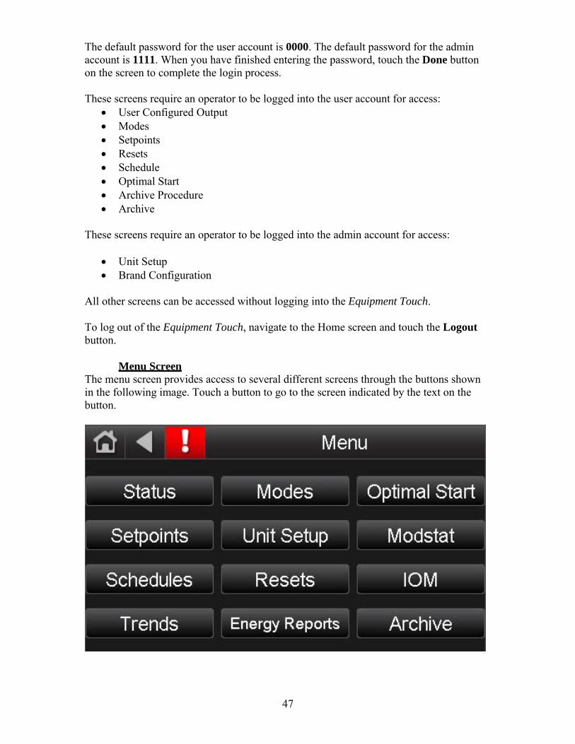
47
The default password for the user account is 0000. The default password for the admin account is 1111. When you have finished entering the password, touch the Done button on the screen to complete the login process.
These screens require an operator to be logged into the user account for access:
User Configured Output Modes Setpoints Resets Schedule Optimal Start Archive Procedure Archive
These screens require an operator to be logged into the admin account for access:
Unit Setup Brand Configuration
All other screens can be accessed without logging into the Equipment Touch.
To log out of the Equipment Touch, navigate to the Home screen and touch the Logout button.
Menu Screen
The menu screen provides access to several different screens through the buttons shown in the following image. Touch a button to go to the screen indicated by the text on the button.

48
Status Screen The status screen provides important unit status information.
The following points are available on this screen:
Point Value Occupancy Unoccupied / OccupiedFan Off / OnBurner / Heater Off / OnCooling Stage 1 Off / OnCooling Stage 2 Off / OnCooling Stage 3 Off / On Cooling Stage 4 Off / OnRoom Temp °FDischarge Air Temp °FOutside/Inlet Air Temp °FMixed Air Temp °FOutside Air % % Building Pressure ” w.c.Damper Volts VBurner / Heater Volts VSafety Circuit Open / ClosedActual Equivalent Temperature Rise
°F
Maximum Equivalent Temperature Rise
°F
Energy Save Mode 1 Off / On Energy Save Mode 2 Off / OnEnergy Save Mode 3 Off / OnEnergy Save Mode 4 Off / On

49
The Status screen provides buttons to access the Cycles and Runtimes, Setpoints, Resets, and Schedules screens.
Cycles and Runtimes Screen The Cycles and Runtimes screen allows to view fan, burner, and cooling cycles since last reset. The fan, burner, and cooling cycles since the initial program download are also monitored and function like the odometer in a car in that they cannot be reset. For example, “Fan Cycles” shows the number of times the fan has cycled on since the last reset, whereas “Fan Cycles (All)” shows the number of times the fan has cycled on since the program was downloaded to the module (typically at the factory).
The following points are available on this screen:
Point Value Fan Cycles # of cycles since resetFan Cycles (All) # of cycles since beginning Fan Hours # of run hours since resetFan Hours (All) # of run hours since beginningBurner Cycles # of cycles since resetBurner Cycles (All) # of cycles since beginningBurner Hours # of run hours since resetBurner Hours (All) # of run hours since beginning Cooling 1 Cycles # of cycles since resetCooling 1 Cycles (All) # of cycles since beginningCooling 1 Hours # of run hours since resetCooling 1 Hours (All) # of run hours since beginningCooling 2 Cycles # of cycles since resetCooling 2 Cycles (All) # of cycles since beginning Cooling 2 Hours # of run hours since resetCooling 2 Hours (All) # of run hours since beginning

50
Cooling 3 Cycles # of cycles since resetCooling 3 Cycles (All) # of cycles since beginningCooling 3 Hours # of run hours since resetCooling 3 Hours (All) # of run hours since beginning Cooling 4 Cycles # of cycles since resetCooling 4 Cycles (All) # of cycles since beginningCooling 4 Hours # of run hours since resetCooling 4 Hours (All) # of run hours since beginning
The Cycles and Runtimes screen provides buttons to access the Status, Resets, and Schedules screens.
Setpoints Screen
The Setpoints screen allows the operator to enter the desired unit setpoints that will determine when heating and cooling will be enabled.
The following points are available on this screen:
Point Value Heating Occupied SP 40°F – 130°FHeating Setback SP 40°F – 130°FHeating Min DAT SP 40°F – 130°FHeating Max DAT SP 40°F – 130°F Heating DAT SP 40°F – 130°FHeating Economizer SP 40°F – 130°FCooling Occupied SP 40°F – 130°FCooling Setback SP 40°F – 130°FCooling Min DAT SP 40°F – 130°FCooling Max DAT SP 40°F – 130°F Cooling DAT SP 40°F – 130°FCooling Economizer SP 40°F – 130°F

51
Htg/Clg Changeover SP 40°F – 130°FMixed Air Temp SP 30°F – 90°FFreezestat SP 35°F – 80°FFreezestat Buffer Time SP 3 – 9 minutes Manual Ventilation SP 0% – 100%Minimum Ventilation SP 0% – 100%Building Pressure SP -0.05” w.c. – +0.05” w.c.Optimal Start Touch this button to access
the Optimal Start settings
The setpoints screen provides buttons to access the Optimal Start, Status, Resets, and Schedules screens.
Optimal Start Screen
The Optimal Start screen allows the operator to configure Optimal Start settings.
The following points are available on this screen:
Point Value Optimal Start Limit 0 – 6.0 hoursHeating Design Temp -40°F – 130°FHeating Capacity 0°F/hr – 10°F/hrCooling Design Temp -40°F – 130°F Cooling Capacity 0°F/hr – 10°F/hr
The optimal start screen provides buttons to access the Setpoints, Status, and Schedules screens. See the Heating/Ventilation/Cooling Operating Modes section of this manual for more information about Optimal Start functionality.

52
Schedules Screen The Schedules screen lets you view, add, edit, or delete BACnet schedules in the controller.
See Unit Operating Modes > MRT-Touch Controls > Scheduling Time Clock or Unit Operating Modes > MDT-Touch Controls > Scheduling Time Clock in this manual for information about viewing and configuring schedules for the unit.

53
Trends Screen The Trends screen allows the operator to view trends.
To view trends, touch the Trends button. The Trend Selector screen allows the operator to view trends for points that have trending enabled. Select up to four points to view at a time and select whether that point is analog/numerical (49°F, 0.2” w.c.) or digital (off/on). Touch the Next button.
The Trend Scaling screen displays the Date/Time of the oldest and newest trend samples in the controller for the selected point(s). Touch a field to enter a new date or time. For analog points, The Min Y and Min X fields show the range of the Y axis based on the lowest and highest trend sample values for the selected point(s). Touch either field and edit the value to define a new range for the Y axis. Touch Display Trends. A trend graph will display on the screen.

54
Modes Screen The Modes screen allows the operator to select the Unit and Damper Mode.
The following points are available on this screen:
Point Value Unit Mode Off / Manual / AutoDamper Mode MA Temp Ctrl / Bldg Pres Ctrl / Manual
The Modes screen provides buttons to access the Setpoints, Status, and Schedule screens.

55
Unit Setup Screen The Unit Setup screen allows the user to select the desired Control System and Fuel Type for the unit. These parameters are configured at the factory for each particular unit. Do not change any of these values without first contacting the factory as unit operation may be severely affected.
The following points are available on this screen:
Point Value Control System MRT / MDTFuel Type Propane Gas / Natural GasMinimum Fuel Input 0 MBH – 20000 MBHMaximum Fuel Input 0 MBH – 20000 MBHUnit Altitude 0 ft – 8000 ft Duct Heater Size GTD-160 / GTD-320 / GTD-
480 Use VFD? No / YesMotor Minimum Speed 0 Hz – 60 HzMotor Maximum Speed 0 Hz – 60 HzMotor Volts VMotor Full Load Amps AControl Transformer Load VA Cooling Stage 1 Load kWCooling Stage 2 Load kWCooling Stage 3 Load kWCooling Stage 4 Load kW
The Unit Setup screen provides buttons to access the Brand Configuration, Communication (BACnet), and User Configured Output screens.

56
Brand Configuration Screen The Brand Configuration screen allows the user to select the desired brand name that is to be displayed on the Home screen. This parameter is configured at the factory and typically does not need to be changed in the field. It does not affect unit operation.
Touch the white radio button next to the appropriate brand name to select the brand. The radio button will fill in with a blue circle to indicate your selection. The following Brand Configuration options are available:
Applied Air Temprite Industries Sterling HVAC Trane Co. LJ Wing Moffitt Sierra
The Brand Configuration screen provide a button to access the Unit Setup screen.

57
Resets Screen The Resets screen allows the user to reset alarms and heating and cooling counters.
The following points are available on this screen:
Point Value Alarms Off / OnFan Counter Off / On Heating Counter Off / OnCooling 1 Counter Off / OnCooling 2 Counter Off / OnData Reset Off / On
The Resets screen provides buttons to access the Status, Setpoints, and Setup screens.
This section should assist the user in resetting alarms and cycle counters which have been displayed on the Equipment Touch.
Alarms Reset There are five methods that can be used to reset alarms on an MRT-Touch or MDT- Touch system. The first, second, and third methods require the Equipment Touch. The fourth and fifth methods can be used if an Equipment Touch is not immediately available at the unit or the unit is configured for MRT and MDT control and does not use the Equipment Touch.
All methods can be used on a unit that has an I/O Zone 583 controller. All methods except the fourth method can be used on a unit that has an I/O Flex 6126 controller.
The first method to reset alarms:
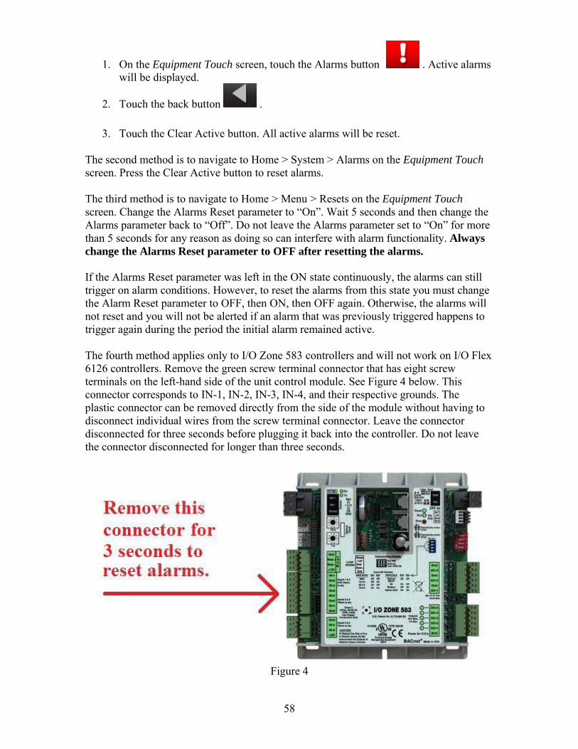
58
1. On the Equipment Touch screen, touch the Alarms button . Active alarms will be displayed.
2. Touch the back button .
3. Touch the Clear Active button. All active alarms will be reset. The second method is to navigate to Home > System > Alarms on the Equipment Touch screen. Press the Clear Active button to reset alarms.
The third method is to navigate to Home > Menu > Resets on the Equipment Touch screen. Change the Alarms Reset parameter to “On”. Wait 5 seconds and then change the Alarms parameter back to “Off”. Do not leave the Alarms parameter set to “On” for more than 5 seconds for any reason as doing so can interfere with alarm functionality. Always change the Alarms Reset parameter to OFF after resetting the alarms.
If the Alarms Reset parameter was left in the ON state continuously, the alarms can still trigger on alarm conditions. However, to reset the alarms from this state you must change the Alarm Reset parameter to OFF, then ON, then OFF again. Otherwise, the alarms will not reset and you will not be alerted if an alarm that was previously triggered happens to trigger again during the period the initial alarm remained active.
The fourth method applies only to I/O Zone 583 controllers and will not work on I/O Flex 6126 controllers. Remove the green screw terminal connector that has eight screw terminals on the left-hand side of the unit control module. See Figure 4 below. This connector corresponds to IN-1, IN-2, IN-3, IN-4, and their respective grounds. The plastic connector can be removed directly from the side of the module without having to disconnect individual wires from the screw terminal connector. Leave the connector disconnected for three seconds before plugging it back into the controller. Do not leave the connector disconnected for longer than three seconds.
Figure 4

59
The fifth method is to turn off the unit’s main disconnect switch. All active alarms will be reset. However, an alarm will regenerate if the condition that triggered the alarm is still present after power is restored, no matter which method was used to reset the alarms. For example, if the Room Sensor Failure alarm is active when the alarms are reset but the unit is still configured for MRT-Touch control and the room sensor is disconnected, the Room Sensor Failure alarm will regenerate.
Resetting alarms does not fix the underlying problem that resulted in the alarm being generated. Refer to the Diagnostics section of this manual for troubleshooting guidelines related to each potential alarm.
An Equipment Touch or PC is required to view alarms. A history of alarms that have been generated in the controller can be viewed by navigating to Home > System > Alarms on the Equipment Touch and then touching the Return-To-Normal or Manually Cleared buttons. Return-To-Normal shows alarm conditions that have reset automatically once the condition that caused the alarm has gone away. Manually Cleared shows alarms that the user has manually reset through any of the previously described methods.
Fan Counter The Fan Cycles status records each fan start since the last reset. The Fan Hours status records the fan runtime since the last reset. To reset these values, navigate to Home > Menu > Resets. Change the Fan Counter parameter to “On” and wait 5 seconds. Change the Fan Counter parameter back to “Off”. The Fan Cycles and Fan Hours parameters will reset to zero and will resume normal operation. Leaving the Fan Counter parameter set to “On” will prevent the Fan Cycles and Fan Hours from incrementing so always set the Fan Counter parameter back to “Off” after performing a reset.
The Fan Cycles (All) status records each fan start that has occurred since the controller was programmed. The Fan Hours (All) status records the duration of fan runtime since the controller was programmed. The cycle and runtime functions are similar to the odometer display in a car in that they cannot be reset (the Fan Counter reset has no effect on these values). These values are intended to provide an indication of the total number of fan cycles and fan run hours the unit has experienced.
Burner Counter The Burner Cycles status records each burner start since the last reset. The Burner Hours status records the burner runtime since the last reset. To reset these values, navigate to Home > Menu > Resets. Change the Burner Counter parameter to “On” and wait 5 seconds. Change the Burner Counter parameter back to “Off”. The Burner Cycles and Burner Hours parameters will reset to zero and will resume normal operation. Leaving the Burner Counter parameter set to “On” will prevent the Burner Cycles and Burner Hours from incrementing so always set the Burner Counter parameter back to “Off” after performing a reset.
The Burner Cycles (All) status records each burner start that has occurred since the controller was programmed. The Burner Hours (All) status records the duration of burner runtime since the controller was programmed. The cycle and runtime functions are similar to the odometer display in a car in that they cannot be reset (the Burner Counter reset has no effect on these values). These values are intended to provide an indication of the total number of burner cycles and burner run hours the unit has experienced.

60
Cooling 1 Counter The Cooling 1 Cycles status records each cooling stage 1 start since the last reset. The Cooling 1 Hours status records the cooling stage 1 runtime since the last reset. To reset these values, navigate to Home > Menu > Resets. Change the Cooling 1 Counter parameter to “On” and wait 5 seconds. Change the Cooling 1 Counter parameter back to “Off”. The Cooling 1 Cycles and Cooling 1 Hours parameters will reset to zero and will resume normal operation. Leaving the Cooling 1 Counter parameter set to “On” will prevent the Cooling 1 Cycles and Cooling 1 Hours from incrementing so always set the Cooling 1 Counter parameter back to “Off” after performing a reset.
The Cooling 1 Cycles (All) status records each cooling stage 1 start that has occurred since the controller was programmed. The Cooling 1 Hours (All) status records the duration of cooling stage 1 runtime since the controller was programmed. The cycle and runtime functions are similar to the odometer display in a car in that they cannot be reset (the Cooling 1 Counter reset has no effect on these values). These values are intended to provide an indication of the total number of cooling stage 1 cycles and cooling stage 1 run hours the unit has experienced.
Cooling 2 Counter The Cooling 2 Cycles status records each cooling stage 2 start since the last reset. The Cooling 2 Hours status records the cooling stage 2 runtime since the last reset. To reset these values, navigate to Home > Menu > Resets. Change the Cooling 2 Counter parameter to “On” and wait 5 seconds. Change the Cooling 2 Counter parameter back to “Off”. The Cooling 2 Cycles and Cooling 2 Hours parameters will reset to zero and will resume normal operation. Leaving the Cooling 2 Counter parameter set to “On” will prevent the Cooling 2 Cycles and Cooling 2 Hours from incrementing so always set the Cooling 2 Counter parameter back to “Off” after performing a reset.
The Cooling 2 Cycles (All) status records each cooling stage 2 start that has occurred since the controller was programmed. The Cooling 2 Hours (All) status records the duration of cooling stage 2 runtime since the controller was programmed. The cycle and runtime functions are similar to the odometer display in a car in that they cannot be reset (the Cooling 2 Counter reset has no effect on these values). These values are intended to provide an indication of the total number of cooling stage 2 cycles and cooling stage 2 run hours the unit has experienced.
Data Reset Change the Data Reset reset field to ON for two seconds, then OFF. Electricity, fuel, and CO2 data will be reset. This data cannot be recovered once the reset has been activated.

61
Calibration Screen The Calibration screen allows manually start a calibration period for the airflow station, view the DC voltage output by the flow station pressure transducer (PT-15), and see how much time has elapsed during the calibration period.
The following points are available on this screen:
Point Value Calibrate Off / OnFlow Station Transducer Volts
0 – 5 VDC
Calibration Time Elapsed Minutes and seconds
Calibrate The calibration function forces the controller to recalibrate the return airflow station. This function occurs automatically each day. At 3:00am, the flag is set within the controller to trigger the calibration immediately if the fan is already running or the next time the fan starts. A fan status signal from the fan status relay is required for the calibration function to start.
The calibration function drives the damper position to 100% return air and calculates an average of the return air pressure over the 5 minute calibration period. The controller stores this value until the next calibration. The DC voltage output from the flow station pressure transducer (PT-15) is displayed on this screen as Flow Station Transducer Volts. This voltage must be greater than 2.0 volts DC during the calibration period for the airflow station calibration to be successful. Upon the calibration period ending, normal damper operation will resume.
The controller will automatically and continuously calculate the percentage of outside air and return air as the damper position changes during the course of normal operation. The controller compares the instantaneous pressure reading from the return airflow station

62
pressure transducer to the value it stored following the 100% return air calibration period to generate an accurate instantaneous percentage of outside air and return air.
To manually recalibrate the airflow station, navigate to Home > Menu > Resets and change the Calibrate parameter to “On” or short terminals IN-5 and IN-6 to the Gnd terminal on the I/O Zone 583 controller. The time values displayed in the Calibration Time Elapsed field will begin to increase a few seconds later. Once these values have begun to increase, indicating that calibration period has started, change the Calibrate parameter to “Off”. After 5 minutes, the calibration period will automatically end and normal damper operation will resume according to which dampers mode is selected.
Refer to the Damper Operation section of this manual for the complete damper operation sequence.
The Calibration screen provides buttons to access the Status, Schedules, and Setup screens
Energy Reports Screen
The Energy Reports screen allows navigate to the Electricity Data, Fuel Data and CO2 Data screens. Not all types of data are available on all units.
Select Electricity Data, Fuel Data or CO2 Data to see detailed estimated consumption statistics.

63
Electricity Data Screen The Electricity Data screen allows the user to monitor equipment electricity consumption. Electricity consumption is estimated based on supply fan motor voltage and current, control transformer load, and cooling stage 1 and 2 loads.
The following points are available on the Electricity Data screen:
Point Value Instantaneous Usage kWUsage Today kWhUsage Yesterday kWhUsage Month-to-Date kWhUsage Last Month kWh Usage Year-to-Date kWhUsage Last Year kWhPeak Demand Today kWPeak Demand Yesterday kWPeak Demand Month-to- Date
kW
Peak Demand Last Month kW Peak Demand Year-to-Date kWPeak Demand Last Year kW
The Electricity Data screen provides buttons to access the Setpoints, Status, and Resets screens.
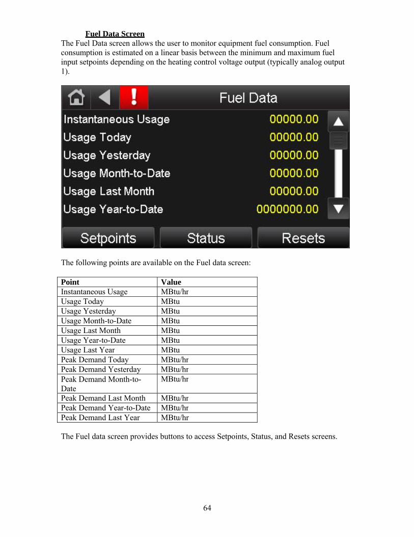
64
Fuel Data Screen The Fuel Data screen allows the user to monitor equipment fuel consumption. Fuel consumption is estimated on a linear basis between the minimum and maximum fuel input setpoints depending on the heating control voltage output (typically analog output 1).
The following points are available on the Fuel data screen:
Point Value Instantaneous Usage MBtu/hrUsage Today MBtuUsage Yesterday MBtuUsage Month-to-Date MBtuUsage Last Month MBtuUsage Year-to-Date MBtu Usage Last Year MBtuPeak Demand Today MBtu/hrPeak Demand Yesterday MBtu/hrPeak Demand Month-to- Date
MBtu/hr
Peak Demand Last Month MBtu/hrPeak Demand Year-to-Date MBtu/hrPeak Demand Last Year MBtu/hr
The Fuel data screen provides buttons to access Setpoints, Status, and Resets screens.
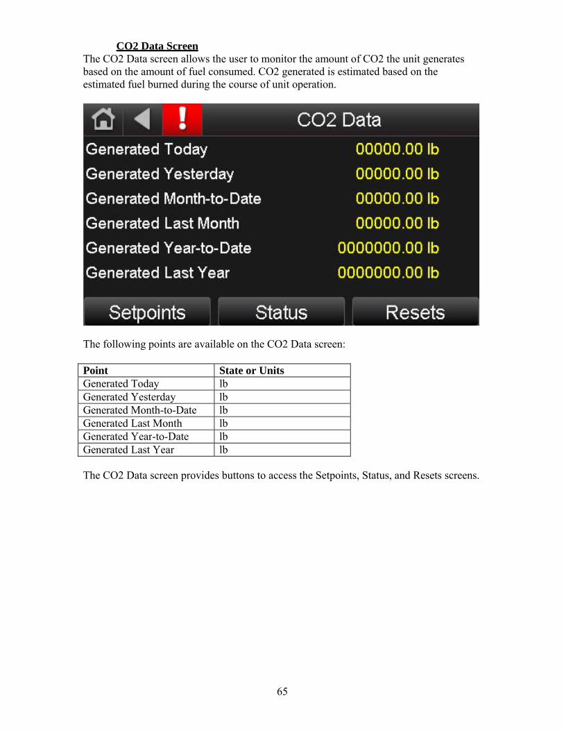
65
CO2 Data Screen The CO2 Data screen allows the user to monitor the amount of CO2 the unit generates based on the amount of fuel consumed. CO2 generated is estimated based on the estimated fuel burned during the course of unit operation.
The following points are available on the CO2 Data screen:
Point State or Units Generated Today lbGenerated Yesterday lb Generated Month-to-Date lbGenerated Last Month lbGenerated Year-to-Date lbGenerated Last Year lb
The CO2 Data screen provides buttons to access the Setpoints, Status, and Resets screens.

66
User Configured Output Help Screen The User Configured Output Help screen provides help information regarding setting up the user configured output.
The User Configured Output Help screen provides buttons to access the User Configured Output Setup and Setpoints screens.
User Configured Output Setup Screen
The User Configured Output Setup screen provides access to User Configured Output setpoints and status information.

67
The following points are available on this screen:
Point State or Units User Control SP -9999.99 – 9999.99User Input Variable -9999.99 – 9999.99User Output 0% – 100% PID Select Direct Acting / Reverse
ActingHigh Input Value -9999.99 – 9999.99Low Input Value -9999.99 – 9999.99Maximum User SP -9999.99 – 9999.99Minimum User SP -9999.99 – 9999.99
The User Configured Output Setup screen provides buttons to access the Setpoints, Status, and Help screens.
This function is applicable to units without modulating return air dampers only. The User Configured PID Control function allows the user to control an analog output based on a user defined analog input and setpoint. See the Typical Wiring and Unit Controller Specification sections of this manual for more information regarding the inputs and outputs. This function also allows the user to select the PID type (direct or reverse acting) and establish upper and lower control limits. Five keypad entries define the operational parameters. These parameters are: User Control Setpoint, Minimum User Setpoint, Maximum User Setpoint, Low Input Value, and High Input Value. The low and high input values describe the input transducer range. The control setpoint is the primary operational parameter while the minimum and maximum setpoints describe the extents of the desired operating range and provide secondary control as described below. The allowable range for all of these parameters is –9999.99 - +9999.99.
The analog input and output are polarity sensitive and can be configured for different types of inputs. See the Typical Wiring and Unit Controller Specification sections of this manual for more information regarding the inputs and outputs.
The analog input must be connected to IN-2. This input must be configured for either of two different types of input signals:
0-5Vdc: The output impedance must not exceed 10KΩ. The input impedance of the controller is 1MΩ. This input is polarity sensitive. Be sure the connections from the source are correctly polarized at the controller.
Thermistor: Precon type 2 (10k ohm at 77°F) Input voltages should range between 0.489V and 3.825V. See the wiring diagrams for recirculating model units for typical connections of transducers.
The IN-2 configuration jumpers on the controller must be set for the appropriate input signal.
A contact closure between the appropriate terminals on the unit’s terminal strip located in the unit’s main control panel will drive the output to 100%. See the

68
Typical Wiring Schematic and Multiplexed Input sections of this manual for more information.
Direct Acting: The controller output is modulated by a PID loop from 0% to 100% based on the User Control setpoint and the input signal. As the input signal increases the output voltage increases. Additionally, a secondary control acts to override the PID loop to scale the output as follows.
If the input variable equals the User Control setpoint, the output will be determined by the PID loop. In this situation the override has no effect on the output value.
If the input variable is above the User Control setpoint, the output could increase from 0% to 100% as the input variable increases from the User Control setpoint to the Max User setpoint. In this situation the output value is the greater of the PID output or the override output.
If the input variable is below the User Control setpoint, the output could decrease from 100% to 0% as the input variable decreases from the User Control setpoint to the Min User setpoint. In this situation the output value is the lesser of the PID output or the override output. See the following example.
Assume the user wishes to control a chilled water valve using a temperature transducer. The control variable will be supply air temperature. As the supply air temperature increases, the chilled water valve should open to lower the temperature. The temperature transducer has a range of 50ºF - 85ºF. The user would like the supply air temperature to be 75ºF but does not want it to drop below 70ºF or go above 80ºF. The parameters entered on the keypad display will be:
PID Select Direct (as input increases output increases) High Input Val 85ºF Low Input Val 50ºF User Ctrl SP 75ºF Max User SP 80ºF Min User SP 70ºF
The temperature transducer senses the supply air temperature and sends a corresponding signal to the TracRite controller. The controller compares this signal to the desired user control setpoint (75ºF) and uses the PID loop to modulate the output from 0-100% (0- 10Vdc). The output is connected to the chilled water valve that opens or closes to maintain the specified supply air temperature.
If the supply air temperature is 75ºF, the output from the controller will be determined by the PID control sequence, and the override will have no effect on the output.
If the supply air temperature is more than 75ºF, the output from the controller will be determined by the PID control sequence or the override whichever is less.
If the supply air temperature is less than 75ºF, the output from the controller will be determined by the PID control sequence or the override whichever is more.

69
Reverse Acting: The controller output AO-1 is modulated by a PID loop from 0% to 100% based on the User Control setpoint and the input signal to IN-2. As the input signal increases the output voltage decreases. Additionally, a secondary control acts to override the PID loop to scale the output as follows.
If the input variable equals the User Control setpoint, the output will be determined by the PID loop. In this situation the override has no effect on the output value.
If the input variable is above the User Control setpoint, the output could decrease from 100% to 0% as the input variable increases from the User Control setpoint to the Max User setpoint. In this situation the output value is the lesser of the PID output or the override output.
If the input variable is below the User Control setpoint, the output could increase from 0% to 100% as the input variable decreases from the User Control setpoint to the Min User setpoint. In this situation the output value is the greater of the PID output or the override output. See the following example.
Assume the user wishes to control the fan speed using a variable frequency drive (VFD). The VFD input is 0-10Vdc. The control variable will be building pressure. As the building pressure increases, the fan speed should decrease. The building pressure transducer has a range of –0.1” to +0.1”. The user would like the building pressure to be +0.03” but does not want it to drop below 0.0” or go above +0.05”. The parameters entered on the keypad display will be:
PID Select Reverse (as input increases output decreases) High Input Val 0.10Low Input Val -0.10User Ctrl SP 0.03Max User SP 0.05Min User SP 0.00
Max User SP Input > 75ºF?
User Ctrl SP 75ºF PID 0-100%
Input < 75ºF?
Min User SP
80ºF 100%
override scaler
75ºF 0%
75ºF 100%
override scaler
70ºF 0%
>=<
0-100%Output

70
The pressure transducer compares the pressure outside the space to the pressure inside the space and transmits a corresponding signal to the TracRite controller. The controller compares this signal to the desired user control setpoint (0.03”) and uses the PID loop to modulate the output from 0-100% (0-10Vdc). The output is connected to the VFD that changes speed to maintain the specified building pressure.
If the building pressure is 0.03”, the output from the controller will be determined by the PID control sequence, and the override will have no effect on the output.
If the building pressure is more than 0.03”, the output from the controller will be determined by the PID control sequence or the override whichever is less.
If the building pressure is less than 0.03”, the output from the controller will be determined by the PID control sequence or the override whichever is more.
Max User SP Input > .03”?
User Ctrl SP .03” PID 0-100%
Input < .03”?
Min User SP
.05” 0%
override scaler
.03” 100%
.03” 0%
override scaler
.00” 100%
>=<
0-100%Output

71
Module Status (Modstat) Screen The Module Status screen shows allows the operator to select a section of the Module Status (Modstat) report to view. Touch a button to see one of the following sections of the Module Status report: Device Data, Driver Data, Reset Counters, System Errors, Warnings, Information, Hardware, Database, or Network.
For example, the screens below show examples of the Driver Data and Reset Counters information.

72
A factory support person will typically ask the operator to navigate through the Module Status report if a problem with the controls/controller is suspected to determine the version of the control program the unit is running. If the number of programs (PRGs) initialized does not match the number of PRGs running on the Module Status > Device Data screen, contact the factory. The Device Data screen will also display the program name and date, in the Application Software Version field.
IOM (Installation, Operation, and Maintenance Manual) Screen
The IOM screen allows the operator to scan a QR code with their smartphone or other mobile device to access an electronic version of the equipment’s Installation, Operation, and Maintenance manual and this Digital Control System Manual. Follow the on-screen instructions to access the manuals. This function requires an active internet connection on the mobile device.

73
The following image shows an example of a QR code. The entire image must be visible on the touchscreen for the code to scan properly on the mobile device. Touch the scrollbar to adjust the position of the QR code so the whole QR code is visible on the screen before scanning. After scanning the QR code successfully, the QR code scanning app on your mobile device will automatically direct you to the electronic version of the manual.
The IOM screen provides buttons to access the Setpoints, Status, and Schedule screens.

74
Archive Procedure Screen The Archive Procedure screen documents the procedure for archiving the control program in the controller. Use the archive function to create a backup of the current controller settings and setpoints. A snapshot of all parameter overrides gets stored and can be retrieved by formatting the controller. This is a useful feature for restoring to a specific set of known good setpoints if they were changed at some point and you want to go back to what they were before.
Click the Continue button on the Archive Procedure screen to go to the Archive screen.
Archive Screen
The Archive screen allows the operator to complete the archive process.

75
The Current Archive Status, Date, and Time are displayed on this screen. If the Current Archive Status is Invalid, or you want to create a new Archive, touch the checkbox to the right of “Archive Now?” to begin the archive. The archive may take a minute or two to complete.
If the Current Archive Status is "Valid", click the Factory Archive or Field Archive button to see the steps for restoring the factory or field archive. Click the "Continue" button when you are ready to proceed.
The factory archive is created at the factory when the program and touchscreen files are downloaded to the controller. The factory archive cannot be overwritten in the field.
The field archive is created whenever an archive is initiated from the touchscreen. The old field archive is overwritten any time a new field archive is performed. See the following steps to restore from a factory or field archive. Restore from a factory archive when you want to restore the controller to the factory default settings. Restore from a field archive when you want to restore the controller to a default set of field settings.
I/O Zone 583 Restoring from a factory or field archive requires putting a jumper on the I/O Zone 583’s format pin. The picture below should aid in located this jumper.
To restore from a factory archive:
1. Turn off the I/O Zone 583 controller. 2. Set both rotary address switches to zero (0). 3. Take the jumper from the GAIN=1 pins and put it on the format pins. 4. Turn on the controller. 5. Run and Error LEDs cycle 3 times opposite of each other, the return to normal
operation once the process is complete. The Run LED flashes once per second
76
during normal operation. Navigate to Home > System > Setup > Module Setup > Set Time and Date to set the time and date.
6. Move the jumper from the format pins back to the GAIN=1 pins.
To restore from a field archive:
1. Turn off the I/O Zone 583 controller. 2. Set both rotary address switches any non-zero numbers. 3. Take the jumper from the GAIN=1 pins and put it on the format pins. 4. Turn on the controller. 5. Run and Error LEDs cycle 3 times opposite of each other, the return to normal
operation once the process is complete. The Run LED flashes once per second during normal operation. Navigate to Home > System > Setup > Module Setup > Set Time and Date to set the time and date.
6. Move the jumper from the format pins back to the GAIN=1 pins.

77
I/O Flex 6126 Restoring from a factory or field archive requires putting a jumper on the I/O Flex 6126’s format pin. The picture below should aid in located this jumper.

78
To restore from a factory archive:
1. Turn off the I/O Zone 583 controller. 2. Set both rotary address switches to zero (0). 3. Take the jumper from the Aux Pwr Out pins and put it on the format pins.
Note the position of the Aux Pwr Out jumper so you can put it back the way it was when you are done with this procedure.
4. Turn on the controller. 5. Run and Error LEDs cycle 3 times opposite of each other, the return to normal
operation once the process is complete. The Run LED flashes once per second during normal operation. Navigate to Home > System > Setup > Module Setup > Set Time and Date to set the time and date.
6. Return the jumper on the format pins to the Aux Pwr Out pins.
To restore from a field archive:
1. Turn off the I/O Zone 583 controller. 2. Set both rotary address switches any non-zero numbers. 3. Take the jumper from the Aux Pwr Out pins and put it on the format pins.
Note the position of the Aux Pwr Out jumper so you can put it back the way it was when you are done with this procedure.
4. Turn on the controller. 5. Run and Error LEDs cycle 3 times opposite of each other, the return to normal
operation once the process is complete. The Run LED flashes once per second during normal operation. Navigate to Home > System > Setup > Module Setup > Set Time and Date to set the time and date.

79
System Screen The System screen shows the BACnet device instance number, the controller’s time, the room temperature (MRT-Touch systems) or the discharge air temperature (MDT-Touch systems), and provides buttons to access the Module Status, Alarms, Trends, Schedules, Setup, and Browser screens.
Alarms Screen The Alarms Screen displays buttons that allow the operator to access the following screens and functions: Active Alarms, Active Faults, Return-to-Normal, Manually Cleared, and Clear Active.

80
Touch Active Alarms to see all alarms that are currently active in the control program. There are no active fault conditions defined in the control program so the Active Faults screen should remain unavailable. Contact the factory if you receive an active fault message. Touch Return-to-Normal to see alarms that returned to a normal state automatically. Touch Manually Cleared to see alarms that were cleared using the Clear Active button. Touch the Clear Active button to clear all active alarms.
The Equipment Touch can store the 100 most recent alarms.
Setup Screen
The Setup screen provides access to Module Setup, Touchscreen Setup, and Login screens.

81
Module Setup Screen The Module Setup screen provides access to the Set Time and Date, Communication, Router, IP, and Time Master screens.
Touchscreen Setup Screen The Touchscreen Setup screen provides access to several touchscreen setup functions.
Touch the About button to view the Equipment Touch version, the software part number, and the bootloader version. The technical services department may request this information if a hardware issue is suspected.
The Sensor Setup screen is currently unsupported. Do not use this screen.
Touch the Key Click On / Key Click Off to toggle whether the Equipment Touch makes a clicking noise when interacting with items on the display. Touch Key Click Off to turn off the sound when you touch a field or button. Touch Key Click On to turn on the sound.
The Reload Firmware buttons erases the firmware in the touchscreen and renders the touchscreen unusable until new firmware is installed. Do not press this button unless instructed by the factory.
The Passwords button can be used to change the Admin and User account passwords. The device will prompt for the current password and then ask for the new password.
The Inactivity Timeout sets the period of time a user will remain logged into the touchscreen since the last time an item on the display was touched.
The Clean Screen button activates a 60 second timer that counts down automatically and provides the user with time to clean the screen to remove fingerprints with a microfiber or similar cloth without touching something that would affect unit operation. Once
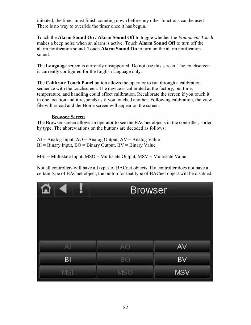
82
initiated, the times must finish counting down before any other functions can be used. There is no way to override the timer once it has begun.
Touch the Alarm Sound On / Alarm Sound Off to toggle whether the Equipment Touch makes a beep noise when an alarm is active. Touch Alarm Sound Off to turn off the alarm notification sound. Touch Alarm Sound On to turn on the alarm notification sound.
The Language screen is currently unsupported. Do not use this screen. The touchscreen is currently configured for the English language only.
The Calibrate Touch Panel button allows the operator to run through a calibration sequence with the touchscreen. The device is calibrated at the factory, but time, temperature, and handling could affect calibration. Recalibrate the screen if you touch it in one location and it responds as if you touched another. Following calibration, the view file will reload and the Home screen will appear on the screen.
Browser Screen
The Browser screen allows an operator to see the BACnet objects in the controller, sorted by type. The abbreviations on the buttons are decoded as follows:
AI = Analog Input, AO = Analog Output, AV = Analog Value BI = Binary Input, BO = Binary Output, BV = Binary Value
MSI = Multistate Input, MSO = Multistate Output, MSV = Multistate Value
Not all controllers will have all types of BACnet objects. If a controller does not have a certain type of BACnet object, the button for that type of BACnet object will be disabled.

83
Each screen shows a list of network-visible BACnet objects with BACnet Object Name, Current Value, and BACnet Object Instance number. The following image shows an example list of AV BACnet objects in a controller.
Touch an object in the above screen to see the details shown below.

84
Set Time and Date Screen The Set Time and Date screen allows the operator to set the local time and date for the controller. Touch the Time or Date fields to enter a new time or date. If the controller communicates with a WebCTRL server or building automation system, the controller will automatically resync the time and date with the server at least once every 24 hours. If the controller does not communicate with a WebCTRL server or building automation system, it may be necessary to change the time and date on the controller to match the local time and date.
Communication (BACnet) Screen The Communication screen allows the operator to edit controller communication settings. Touch a field on this screen to change its value.
85
The BACnet Device Instance, Auto Generate Device ID, Max Masters, and Max Info Frames values may be changed from this screen.
The BACnet device instance number is the unique ID assigned to the controller on the BACnet network.
If Auto Generate Device ID is set to “Yes”, the BACnet device instance number will be automatically generated as 24000 + the rotary address switch settings on the controller. If the rotary address switches are set to 0 and 2, the BACnet device instance will be 24002 (from 24000 + 2). When viewing the controller from the front, the top rotary switch is the tens digit of the address and the bottom rotary switch is the ones digit of the address. For example, with the top switch in the 7 position and the bottom switch in the 2 position, the address on the controller is 72, from (7 × 10) + (2 × 1). The BACnet device instance number in this case would be 24072 (24000 + 72). You will not be able to manually enter a BACnet Device Instance number if Auto Generate Device ID is set to “Yes”.
If Auto Generate Device ID is set to “No”, the operator must manually enter the BACnet device instance number into the BACnet device instance field. This number must be unique on the BACnet network. Duplicate BACnet device instance numbers on the network will cause communication issues.
For BACnet MS/TP networks, the Max Masters and Max Info Frames fields must be configured.
Set Max Masters to the highest MAC address on the MS/TP network. If you later add a device with a higher address, you must change this field to that new address.
Max Info Frames specifies the maximum number of information messages a controller may transmit before it muss pass the token to the next controller. Increasing this number allows the controller to transmit more messages while it has the token, but it also increasese the overall time it takes for the token to pass through the network. For a router, set this value to a high number such as 200. For a non-router, like the I/O Zone 583 or I/O Flex 6126 controllers, set this value according to the following formula:
Max Info Frames = [2 – (devices × (0.002 + (80 / baud)))] / [(600 / baud) × devices]
For example, if the network has 15 devices at 19200 baud, Max Info Frames would be:
Max Info Frames = [2 – (15 × (0.002 + (80 / 19200)))] / [(600 / 19200) × 15]
Max Info Frames = approx. 4.0693 (round down to nearest whole number) = 4
In the case of 15 devices at 19200 baud, you would set Max Info Frames to 4.

86
Protocol Setup This section will assist the user in configuring the DDC controller for one of the available field communication protocols.
The following image shows the location of various configuration jumper and switches:
BACnet MS/TP To configure the controller to communicate in BACnet MS/TP protocol, complete the following procedure:
1. Turn off the power for the I/O Zone 583. 2. Using the rotary address switches on the left-hand side of the controller, set a
unique address. Set the tens switch to the tens digit of the address and set the ones switch to the ones digit. Refer to Equipment Touch User Guide > Navigation > Communication (BACnet) Screen for more information about how the rotary address switches affect the device address.
3. Set the Communications Selection jumper to the EIA-485 position. 4. Set communications dipswitches 1 and 2 on the right-hand side of the controller
to the appropriate position for the desired communication speed (baud rate). All devices on the same network must be set to the same communications speed. Dipswitches are On when the switch is toward the left-hand side of the controller (indicated by a small arrow and the word “On” on the dipswitch block) and Off when the switch is toward the right-hand side of the controller.
Baud rate Dipswitch 1 Dipswitch 2 9,600 bps Off Off19.2 kbps Off On38.4 kbps On Off76.8 kbps On On

87
5. Set communications dipswitches 3 and 4 to the Off position. 6. Connect the communications wiring to the Comm port in the screw terminals
labeled Net +, Net -, and Shield. Use a dedicated 24 AWG to 18 AWG twisted pair wire (EIA-485). Maximum length should be 2,000 ft for 76.8 kbps baud rate or 3,000 feet for 9600 bps, 19.2 kbps, or 38.4 kbps baud rate. Devices should be daisy chained and not star wired. Use the same polarity throughout the network.
7. Turn on power for the I/O Zone 583. 8. Refer to Equipment Touch User Guide > Navigation > Communication (BACnet)
Screen to verify that the BACnet Device Instance is the value you expected.
Modbus To configure the controller to communicate in Modbus protocol, complete the following procedure:
1. Turn off the power for the I/O Zone 583. 2. Using the rotary address switches on the left-hand side of the controller, set a
unique address. Set the tens switch to the tens digit of the address and set the ones switch to the ones digit. Refer to Equipment Touch User Guide > Navigation > Communication (BACnet) Screen for more information about how the rotary address switches affect the device address.
3. Set the Communications Selection jumper to the EIA-485 position. 4. Set communications dipswitches 1 and 2 on the right-hand side of the controller
to the appropriate position for the desired communication speed (baud rate). All devices on the same network must be set to the same communications speed. Dipswitches are On when the switch is toward the left-hand side of the controller (indicated by a small arrow and the word “On” on the dipswitch block) and Off when the switch is toward the right-hand side of the controller.
Baud rate Dipswitch 1 Dipswitch 2 9,600 bps Off Off19.2 kbps Off On38.4 kbps On Off76.8 kbps On On
5. Set communications dipswitches 3 to the Off position and 4 to the On position. 6. Connect the communications wiring to the Comm port in the screw terminals
labeled Net +, Net -, and Shield. Use a dedicated 24 AWG to 18 AWG twisted pair wire (EIA-485). Maximum length should be 2,000 ft for 76.8 kbps baud rate or 3,000 feet for 9600 bps, 19.2 kbps, or 38.4 kbps baud rate. Devices should be daisy chained and not star wired. Use the same polarity throughout the network.
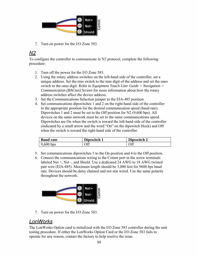
88
7. Turn on power for the I/O Zone 583.
N2 To configure the controller to communicate in N2 protocol, complete the following procedure:
1. Turn off the power for the I/O Zone 583. 2. Using the rotary address switches on the left-hand side of the controller, set a
unique address. Set the tens switch to the tens digit of the address and set the ones switch to the ones digit. Refer to Equipment Touch User Guide > Navigation > Communication (BACnet) Screen for more information about how the rotary address switches affect the device address.
3. Set the Communications Selection jumper to the EIA-485 position. 4. Set communications dipswitches 1 and 2 on the right-hand side of the controller
to the appropriate position for the desired communication speed (baud rate). Dipswitches 1 and 2 must be set to the Off position for N2 (9,600 bps). All devices on the same network must be set to the same communications speed. Dipswitches are On when the switch is toward the left-hand side of the controller (indicated by a small arrow and the word “On” on the dipswitch block) and Off when the switch is toward the right-hand side of the controller.
Baud rate Dipswitch 1 Dipswitch 2 9,600 bps Off Off
5. Set communications dipswitches 3 to the On position and 4 to the Off position. 6. Connect the communications wiring to the Comm port in the screw terminals
labeled Net +, Net -, and Shield. Use a dedicated 24 AWG to 18 AWG twisted pair wire (EIA-485). Maximum length should be 3,000 feet for 9600 bps baud rate. Devices should be daisy chained and not star wired. Use the same polarity throughout the network.
7. Turn on power for the I/O Zone 583.
LonWorks The LonWorks Option card is initialized with the I/O Zone 583 controller during the unit testing procedure. If either the LonWorks Option Card or the I/O Zone 583 fails to operate for any reason, contact the factory to help resolve the issue.

89
To configure the controller to communicate in LonWorks protocol, complete the following procedure:
1. Turn off the power for the I/O Zone 583. 2. Using the rotary address switches on the left-hand side of the controller, set a
unique address. Set the tens switch to the tens digit of the address and set the ones switch to the ones digit. Refer to the Equipment Touch User Guide > Navigation > Communication (BACnet) Screen section of this manual for more information about how the rotary address switches affect the device address.
3. Set the Communications Selection jumper to the EIA-485 position. 4. Set communications dipswitches 1 and 2 on the right-hand side of the controller
to the appropriate position for the desired communication speed (baud rate). All devices on the same network must be set to the same communications speed. Dipswitches are On when the switch is toward the left-hand side of the controller (indicated by a small arrow and the word “On” on the dipswitch block) and Off when the switch is toward the right-hand side of the controller.
Baud rate Dipswitch 1 Dipswitch 2 9,600 bps Off Off19.2 kbps Off On38.4 kbps On Off76.8 kbps On On
5. Set communications dipswitches 3 and 4 to the On position. 6. Connect the LON network to pins 1 and 2 on the LonWorks Option Card. 7. Turn on power for the I/O Zone 583.

90
Diagnostics – Critical Alarm Codes This section should assist the user in troubleshooting critical alarm codes messages that have been displayed on the Equipment Touch. These alarms almost always require the operator to correct the condition and manually reset the alarm before normal unit operation resumes. Exceptions to this rule are noted in the alarm problem descriptions that follow.
ALARM CODE: Freezestat PROBLEM: The controller has detected a low temperature at the unit discharge and has shut off the unit. See Freezestat section of this manual. SOLUTION: If burner was operating prior to shutdown (check prior alarm log)
1. Is the outside air (OA Temp) or room air (Room Temp) displayed on the Equipment Touch reading 150°F or more?
a. Yes. That sensor circuit or the sensor itself is shorted. Unplug the input jack from the TracRite controller. Did the display change to -40°F or less?
1) No. There is a short in the controller input. Replace the controller.
2) Yes. Disconnect the sensor wiring at the sensor. Connect an ohmmeter to the sensor. If it is shorted replace the sensor. At 77°F the resistance should be 10KΩ. See thermistor output curve for other temperatures. If it is not shorted, there is a short in the wiring between the sensor and the input plug. Determine cause and rectify. Refer to Appendix A for a typical 10KΩ thermistor output curve.
b. No. Continue. 2. Is the discharge air temperature (DA Temp), displayed on the Equipment
Touch remote, reading -40°F or less? a. Yes. That sensor circuit or the sensor itself is open. Jumper the input
for the sensor. Did the display change to 150°F or more? 1) No. There is an open in the controller input. Replace the
controller. 2) Yes. Disconnect the sensor wiring at the sensor. Connect an
ohmmeter to the sensor. If it is open replace the sensor. At 77°F the resistance should be 10KΩ. See thermistor output curve for other temperatures. If it is not open, there is a break in the wiring between the sensor and the input plug. Determine cause and rectify.
b. No. Continue 3. Reset the alarm. Check and note the DC voltage at output for the gas valve
modulation. Set the Heating Occupied and Night Setback Setpoints for 130°F. Set the Heating Minimum and Maximum DA Temp Setpoints for 130°F. Did the Burner VDC, displayed on the Equipment Touch, increase?
a. No. Unless the outside air temperature is extremely warm the Burner VDC should have increased to 7.5VDC or more. Close the manual main gas valve closest to the burner and measure the discharge air temperature. Is it less than 130°F?
1) Yes. There is a problem with the controller program or controller itself. Contact the factory.

91
2) No. The outside air temperature is too hot to determine the actual cause of the problem. Reset the alarm and recheck when the outside air temperature is much cooler.
b. Yes. This signal is fed to the gas valve modulation signal conditioner. Disconnect the wires from input signal terminals on the signal conditioner and measure the voltage on the wires. Is it the same as the voltage coming from the controller?
1) No. There is an open in the wiring from the controller output. Correct wiring and reconnect the wires to the terminals on the signal conditioner. Be sure the ground wire from the controller output terminal is connected to the signal conditioner’s negative terminal.
2) Yes. Continue. 4. Is there 24VAC on the signal conditioner power terminals?
a. No. Determine cause and rectify. b. Yes. Continue.
5. Is there twice the DC voltage on the signal conditioner’s output terminals as there is on the signal conditioner’s input terminals?
a. No. Replace the signal conditioner. b. Yes. Continue.
6. Is the DC voltage on the modulating valve terminals the same as the DC voltage on the signal conditioner’s output terminals?
a. No. There is a break in the wiring between the signal conditioner and the modulating valve terminals. Determine cause and rectify.
b. Yes. The electronics are working to this point. Continue. 7. Is there sufficient temperature rise for the amount of outside air that is being
delivered to the space? a. No. Follow the instructions in this manual for placing the unit in
Manual damper control mode. Adjust the Manual Ventilation setpoint to 20% outside air. Is there sufficient temperature rise for the amount of outside air that is being delivered to the space?
1) No. Contact the factory. 2) Yes. Continue.
b. Yes. Continue. 8. Verify there is sufficient inlet gas pressure. Verify the modulating valve is
properly adjusted. Verify the burner orifices are clear of obstruction. Contact the factory.
SOLUTION: If burner was not operating prior to shutdown (check prior alarm log) 1. Is there a prior alarm such as Safety Circuit Open, Check Airflow Switches, or
Flame Failure? a. Yes. See the Diagnostic section for the previous alarm. b. No. Continue.
2. Is the room air (Room Temp) displayed on the Equipment Touch, reading 150°F or more?
a. Yes. The sensor circuit or the sensor itself is shorted. Unplug the input jack from the TracRite controller. Did the display change to -40°F or less?
1) No. There is a short in the controller input. Replace the controller.
2) Yes. Disconnect the sensor wiring at the sensor. Connect an ohmmeter to the sensor. If it is shorted replace the sensor. At

92
77°F the resistance should be 10KΩ. See thermistor output curve for other temperatures. If it is not shorted, there is a short in the wiring between the sensor and the input plug. Determine cause and rectify. Refer to Appendix A for a typical 10KΩ thermistor output curve.
b. No. Continue. 3. Is the discharge air temperature (DA Tempt), displayed on the Equipment
Touch, reading -40°F or less? a. Yes. The discharge air temperature sensor circuit or the sensor itself is
open. Jumper the input for the sensor. Did the display change to 150°F or more?
1) No. There is an open in the controller input. Replace the controller.
2) Yes. Disconnect the discharge air temperature sensor wiring at the sensor. Connect an ohmmeter to the sensor. If it is open replace the sensor. At 77°F the resistance should be 10KΩ. See thermistor output curve for other temperatures. If it is not open, there is a break in the wiring between the sensor and the input plug. Determine cause and rectify.
b. No. Continue 4. Reset the alarm. Check and note the DC voltage at output for the gas valve
modulation. Set the Heating Occupied and Night Setback Setpoints for 130°F. Set the Heating Minimum and Maximum DA Temp Setpoints for 130°F. Did the Burner VDC, displayed on the Equipment Touch, increase?
a. No. Unless the outside air temperature is extremely warm the Burner VDC should have increased to 7.5VDC or more. Close the manual main gas valve closest to the burner and measure the discharge air temperature. Is it less than 130°F?
1) Yes. There is a problem with the controller program or controller itself. Contact the factory.
2) No. The outside air temperature is too hot to determine the actual cause of the problem. Reset the alarm and recheck when the outside air temperature is much cooler.
b. Yes. This signal is fed to the signal conditioner. Disconnect the wires from the signal conditioner’s input signal terminals and measure the voltage on the wires. Is it the same as the voltage coming from the controller?
1) No. There is an open in the wiring from the controller output. Correct wiring and reconnect the wires to the terminals on the signal conditioner. Be sure the wire from the controller’s ground terminal is connected to the signal conditioner’s ground terminal.
2) Yes. Continue. 5. Is there 24VAC on the signal conditioner power terminals?
a. No. Determine cause and rectify. b. Yes. Continue.
6. Is there twice the DC voltage on the signal conditioner’s output terminals as there is on the signal conditioner’s input terminals?
a. No. Replace the signal conditioner. b. Yes. Continue.
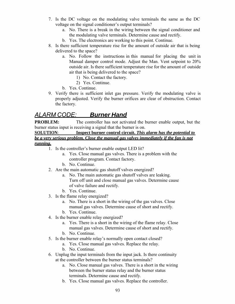
93
7. Is the DC voltage on the modulating valve terminals the same as the DC voltage on the signal conditioner’s output terminals?
a. No. There is a break in the wiring between the signal conditioner and the modulating valve terminals. Determine cause and rectify.
b. Yes. The electronics are working to this point. Continue. 8. Is there sufficient temperature rise for the amount of outside air that is being
delivered to the space? a. No. Follow the instructions in this manual for placing the unit in
Manual damper control mode. Adjust the Man. Vent setpoint to 20% outside air. Is there sufficient temperature rise for the amount of outside air that is being delivered to the space?
1) No. Contact the factory. 2) Yes. Continue.
b. Yes. Continue. 9. Verify there is sufficient inlet gas pressure. Verify the modulating valve is
properly adjusted. Verify the burner orifices are clear of obstruction. Contact the factory.
ALARM CODE: Burner Hand PROBLEM: The controller has not activated the burner enable output, but the burner status input is receiving a signal that the burner is on. SOLUTION: Inspect burner control circuit. This alarm has the potential to be a very serious problem. Close the manual gas valves immediately if the fan is not running.
1. Is the controller’s burner enable output LED lit? a. Yes. Close manual gas valves. There is a problem with the
controller program. Contact factory. b. No. Continue.
2. Are the main automatic gas shutoff valves energized? a. No. The main automatic gas shutoff valves are leaking.
Turn off unit and close manual gas valves. Determine cause of valve failure and rectify.
b. Yes. Continue. 3. Is the flame relay energized?
a. No. There is a short in the wiring of the gas valves. Close manual gas valves. Determine cause of short and rectify.
b. Yes. Continue. 4. Is the burner enable relay energized?
a. Yes. There is a short in the wiring of the flame relay. Close manual gas valves. Determine cause of short and rectify.
b. No. Continue. 5. Is the burner enable relay’s normally open contact closed?
a. Yes. Close manual gas valves. Replace the relay. b. No. Continue.
6. Unplug the input terminals from the input jack. Is there continuity at the controller between the burner status terminals?
a. No. Close manual gas valves. There is a short in the wiring between the burner status relay and the burner status terminals. Determine cause and rectify.
b. Yes. Close manual gas valves. Replace the controller.
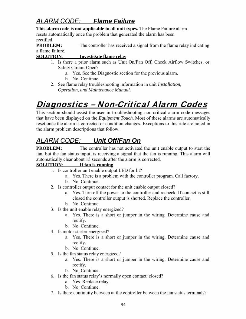
94
ALARM CODE: Flame Failure This alarm code is not applicable to all unit types. The Flame Failure alarm resets automatically once the problem that generated the alarm has been rectified. PROBLEM: The controller has received a signal from the flame relay indicating a flame failure. SOLUTION: Investigate flame relay
1. Is there a prior alarm such as Unit On/Fan Off, Check Airflow Switches, or Safety Circuit Open?
a. Yes. See the Diagnostic section for the previous alarm. b. No. Continue.
2. See flame relay troubleshooting information in unit Installation, Operation, and Maintenance Manual.
Diagnostics – Non-Critical Alarm Codes This section should assist the user in troubleshooting non-critical alarm code messages that have been displayed on the Equipment Touch. Most of these alarms are automatically reset once the alarm is corrected or condition changes. Exceptions to this rule are noted in the alarm problem descriptions that follow.
ALARM CODE: Unit Off/Fan On PROBLEM: The controller has not activated the unit enable output to start the fan, but the fan status input, is receiving a signal that the fan is running. This alarm will automatically clear about 15 seconds after the alarm is corrected. SOLUTION: If fan is running
1. Is controller unit enable output LED for lit? a. Yes. There is a problem with the controller program. Call factory. b. No. Continue.
2. Is controller output contact for the unit enable output closed? a. Yes. Turn off the power to the controller and recheck. If contact is still
closed the controller output is shorted. Replace the controller. b. No. Continue.
3. Is the unit enable relay energized? a. Yes. There is a short or jumper in the wiring. Determine cause and
rectify. b. No. Continue.
4. Is motor starter energized? a. Yes. There is a short or jumper in the wiring. Determine cause and
rectify. b. No. Continue.
5. Is the fan status relay energized? a. Yes. There is a short or jumper in the wiring. Determine cause and
rectify. b. No. Continue.
6. Is the fan status relay’s normally open contact, closed? a. Yes. Replace relay. b. No. Continue.
7. Is there continuity between at the controller between the fan status terminals?
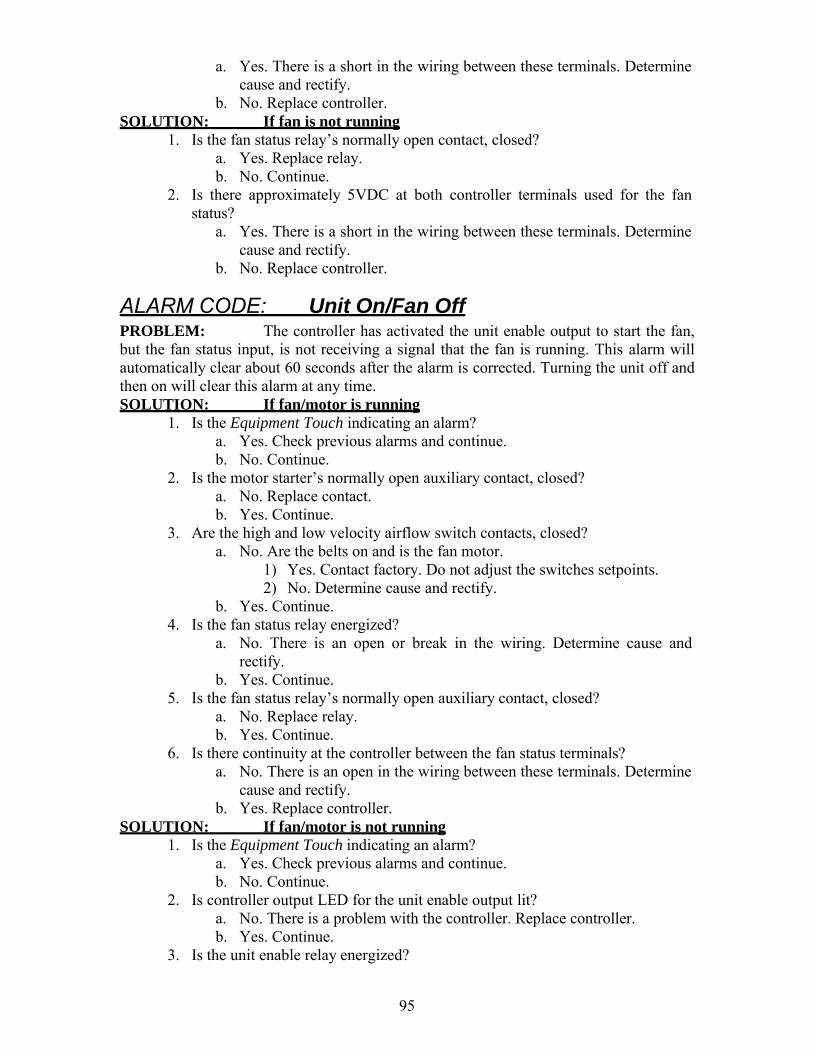
95
a. Yes. There is a short in the wiring between these terminals. Determine cause and rectify.
b. No. Replace controller. SOLUTION: If fan is not running
1. Is the fan status relay’s normally open contact, closed? a. Yes. Replace relay. b. No. Continue.
2. Is there approximately 5VDC at both controller terminals used for the fan status?
a. Yes. There is a short in the wiring between these terminals. Determine cause and rectify.
b. No. Replace controller.
ALARM CODE: Unit On/Fan Off PROBLEM: The controller has activated the unit enable output to start the fan, but the fan status input, is not receiving a signal that the fan is running. This alarm will automatically clear about 60 seconds after the alarm is corrected. Turning the unit off and then on will clear this alarm at any time. SOLUTION: If fan/motor is running
1. Is the Equipment Touch indicating an alarm? a. Yes. Check previous alarms and continue. b. No. Continue.
2. Is the motor starter’s normally open auxiliary contact, closed? a. No. Replace contact. b. Yes. Continue.
3. Are the high and low velocity airflow switch contacts, closed? a. No. Are the belts on and is the fan motor.
1) Yes. Contact factory. Do not adjust the switches setpoints. 2) No. Determine cause and rectify.
b. Yes. Continue. 4. Is the fan status relay energized?
a. No. There is an open or break in the wiring. Determine cause and rectify.
b. Yes. Continue. 5. Is the fan status relay’s normally open auxiliary contact, closed?
a. No. Replace relay. b. Yes. Continue.
6. Is there continuity at the controller between the fan status terminals? a. No. There is an open in the wiring between these terminals. Determine
cause and rectify. b. Yes. Replace controller.
SOLUTION: If fan/motor is not running 1. Is the Equipment Touch indicating an alarm?
a. Yes. Check previous alarms and continue. b. No. Continue.
2. Is controller output LED for the unit enable output lit? a. No. There is a problem with the controller. Replace controller. b. Yes. Continue.
3. Is the unit enable relay energized?

96
a. No. There is an open in the wiring between these terminals. Determine cause and rectify.
b. Yes. Continue. 4. Is the unit enable relay’s normally open contact, closed?
a. No. Replace relay. b. Yes. Continue.
5. Is the motor overload relay tripped? a. Yes. Determine cause, rectify and reset. b. No. Continue.
6. Is the motor starter energized? a. No. There is an open or break in the wiring. Determine cause and
rectify. b. Yes. Check motor and motor wiring.
ALARM CODE: Check Airflow Switches PROBLEM: The controller has activated the unit enable output to start the fan, and detected that the fan is running from a signal at the fan status input. Subsequently, the controller has detected several short momentary openings of the fan status input. The momentary openings must occur at least 4 times within 15 seconds. This alarm requires the operator to correct the condition and manually reset the alarm before normal unit operation resumes. SOLUTION: If high airflow switch is opening. Do not adjust the switch setpoints
1. Are all of the filters in place? a. No. Install filters and continue. b. Yes. Continue.
2. Does the external static pressure match that listed on the rating plate? a. No. Verify all associated ductwork is installed and continue. b. Yes. Continue.
3. Does the fan RPM match that listed on the Spec. Sheet? a. No. Correct to reduced fan speed and continue. b. Yes. Continue.
4. Are the airflow switches’ sensing tubes obstructed? a. Yes. Clear and continue. b. No. Continue.
5. Contact factory. SOLUTION: If low airflow switch is opening. Do not adjust the switch setpoints
1. Does low airflow switch open when the burner is off a. No. Disconnect both pressure sensing tubes from one of the airflow
switches and measure the differential pressure by connecting the high sensing port of a manometer to one of the airflow sensing tubes and the low sensing port to the other. Is the differential pressure approximately the midpoint between the high and low airflow switch setpoints?
1) No. Close the profile opening until the differential pressure is approximately the midpoint between the high and low airflow switch setpoints. Reconnect the sensing tubes, restart the burner, and verify the airflow switch remains closed when the burner is at the maximum rated input. Continue.
2) Yes. Continue. 2. Are all of the filters dirty?

97
a. Yes. Install clean filters and continue. b. No. Continue.
3. Does the external static pressure match that listed on the rating plate? a. No. Verify all associated ductwork is installed as designed, and there
are no obstructions. Continue. b. Yes. Continue.
4. Does the fan RPM match that listed on the Spec. Sheet? a. No. Correct to increased fan speed and continue. b. Yes. Continue.
5. Are the airflow switches’ sensing tubes obstructed? a. Yes. Clear and continue. b. No. Continue.
6. Contact factory.
ALARM CODE: Clogged Filters PROBLEM: The filter air pressure switch has closed between the appropriate terminals on the unit’s terminal strip located in the unit’s main control panel indicating a clogged filter. See the Typical Wiring Schematic, Multiplexed Input, and Clogged Filter sections of this manual for more information. This alarm will automatically clear about 5 seconds after the problem is corrected. SOLUTION: If clogged filter switch is closing.
1. Are the filters dirty? a. Yes. Install clean filters and continue. b. No. Continue.
2. Are the airflow switch sensing tubes obstructed? a. Yes. Clear and continue. b. No. Continue.
3. Is the airflow switch setpoint properly adjusted? a. No. Adjust setpoint. b. Yes. Continue.
4. Are the wires connected to the air pressure switch’s normally open contact? a. No. Rewire switch and continue. b. Yes. Continue.
5. Is the air pressure switch’s normally open contact open? a. No. Disconnect the sensing tubes and recheck. Replace the switch if
contacts do not open. b. Yes. Continue.
6. Find the clogged filter switch on the electrical schematic and identify the control panel terminals to which it is connected. Disconnect the wire from these terminals. Does this clear the alarm?
a. Yes. There is short in the wiring between the terminal strip and the switch. Determine cause and rectify.
b. No. Continue. 7. Unplug the connector from the controller that is connected to the multiplexed
input. Does this clear the alarm? a. Yes. There is short in the wiring of the multiplexed resistors.
Determine cause and rectify. b. No. There is an internal short in the controller. Replace the controller.

98
ALARM CODE: Safety Circuit Open PROBLEM: The controller has detected a failure in the safety circuit. This alarm does not disable the burner and does not affect actual operation of the unit in any way. It merely provides status information to the user indicating that the safety circuit tripped. Though the condition may have already been rectified automatically, the alarm must be manually reset in order to be cleared from the system. Requiring the manual reset gives the user the ability to know that the alarm occurred at some previous time should they wish to further investigate the situation. See the Unit Resets section of this manual for information on how to manually reset the alarm. SOLUTION: If fan is not running (check prior alarm log)
1. Is there a prior alarm such as Unit On/Fan Off or Airflow Sw? a. Yes. See the Diagnostic section for the previous alarm. b. No. Continue.
2. Set Unit Mode to Manual. Did fan start? a. No. See the Diagnostic section for Unit On/Fan Off. b. Yes. Continue.
SOLUTION: If fan is running (check prior alarm log) 1. Is the high temperature limit tripped?
a. Yes. Determine cause and rectify. b. No. Continue.
2. Is the low gas pressure switch closed? a. No. Verify the inlet gas pressure is as specified on the gas piping
diagram. The low gas pressure switch setpoint should not be adjusted. The inlet gas pressure must remain as specified when unit fires at full input. Correct gas pressure and reset switch. If the switch cannot be reset, replace it. See Installation, Operation and Maintenance Manual for more information.
b. Yes. Continue. 3. Is the high gas pressure switch closed?
a. No. Verify the firing rate pressure at full input is as specified on the unit rating plate. The high gas pressure switch setpoint should not be adjusted. The firing rate pressure must remain as specified when unit fires at full input. Correct gas pressure and reset switch. If the switch cannot be reset, replace it. See Installation, Operation and Maintenance Manual for more information.
b. Yes. Continue. 4. Is the safety circuit relay energized?
a. No. Check for loose wiring and rectify. b. Yes. Continue.
5. Is the safety circuit relay’s normally open contact closed? a. No. Replace the relay. b. Yes. Continue.
6. Is there continuity at the controller between the safety status terminals? c. No. There is an open in the wiring between these terminals. Determine
cause and rectify. d. Yes. Replace controller.

99
ALARM CODE: Burner Status Alert PROBLEM: The controller has activated the burner enable output, but the burner status input is not receiving a signal that the burner is on. SOLUTION: Inspect burner control circuit and burner
1. Is there a prior alarm such as Unit On/Fan Off, Check Airflow Switches, or Safety Circuit Open?
a. Yes. See the Diagnostic section for the previous alarm. b. No. Continue.
2. Is the burner enable relay energized? a. No. There is an open in the 24VAC circuit. Determine
cause and rectify. b. Yes. Continue.
3. Is the burner enable relay’s normally open contact closed? a. No. Replace relay. b. Yes. Continue.
4. Is there a pilot flame present? a. No. Refer to the Installation, Operation and Maintenance
Manual for guidance in troubleshooting the flame relay or ignition module.
b. Yes. Continue. 5. Is the flame relay or ignition module main valve terminal
energized? a. No. Refer to the Installation, Operation and Maintenance
Manual for guidance in troubleshooting the flame relay or ignition module.
b. Yes. Continue. 6. Is the gas valve/burner status relay energized?
a. No. There is an open in the main valve control circuit. Determine cause and rectify.
b. Yes. Continue. 7. Is the gas valve/burner status relay’s normally open contact
closed? a. No. Replace relay. b. Yes. Continue.
8. Is there continuity at the controller between the burner status terminals? a. No. There is an open in the wiring between these terminals. Determine
cause and rectify. b. Yes. Replace controller.
ALARM CODE: Insufficient Outside Air PROBLEM: The controller has turned off the burner enable output because the percentage of outside air has dropped below 20% for more than five minutes, and the unit is in the Heating mode. This alarm will automatically clear about 5 seconds after the alarm is corrected. SOLUTION: If heat is desired
1. Are the outside air hood filters or bird screen or any associated outside air ductwork obstructed?
a. Yes. Clear obstruction or change filters. b. No. Continue.
2. Are the outside air and return air dampers and actuators working properly?

100
a. Yes. Continue. b. No. Make necessary adjustments and force the unit to recalibrate. See
Calibrate in the Resets Section of this manual. 3. Are the flow measuring station pitot tubes and pressure tubing clear?
a. Yes. Continue. b. No. Clean and force the unit to recalibrate. See Calibrate in the Resets
Section of this manual. 4. Do the dampers track with a change in the %OA setpoint? The dampers
utilized on the unit are not linear with respect to airflow and openness, and as such, the proportion of outside air damper movement will not be exactly equal to the %OA setpoint. However, at 20% OA the dampers should be approximately ½” open.
a. Yes. Continue. b. No. Check the damper motor and linkage connections. When 24VAC
is powering the damper actuator and the control signal is 0VDC, the outside air damper should be close to a “rattle tight” position and the return air damper should be open. If the 24VAC power is removed, the actuator will draw the outside air damper tightly closed and the return air damper tightly open. When 24VAC is powering the damper actuator and the control signal is 10VDC, the outside air damper should be fully open and the return air damper should be closed.
5. Is there approximately 24VAC at the COM and EXC terminals on the airflow station pressure transducer?
a. Yes. Continue. b. No. Is there 120VAC on the primary side of the low voltage
transformer and 24VAC volt at the transformer secondary? 1) Yes. There is an open in the wiring between the transformer
and the transducer. Locate the wiring problem and rectify. 2) No. If there is 120VAC on the primary and 0VAC on the
secondary, replace the transformer. If there is 0VAC on the primary, there is an open in the wiring supplying power to the transformer. Locate the wiring problem and rectify.
6. Remove both of the plastic tubes from the airflow station pressure transducer and gently blow into the HIGH side port. Caution: The transducer is extremely sensitive. Blowing too hard into the sensing tube may damage the transducer. Is there approximately 5VDC across the COM and OUT terminals of the pressure transducer?
a. Yes. Continue. b. No. The pressure transducer is defective. Replace it.
7. Remove both of the plastic tubes from the airflow station pressure transducer and gently blow into the HIGH side port. Caution: The transducer is extremely sensitive. Blowing too hard into the sensing tube may damage the transducer. Is there approximately 5VDC across the controller input terminals that are connected to the transducer?
a. Yes. There is a problem with the controller. Replace it. b. No. There is an open in the wiring between these pressure transducer
and the TracRite controller terminals. Locate and rectify. SOLUTION: If less outside air is desired
1. Is heat required? a. Yes. The TracRite control system must be in the Heating mode. In
this mode the smallest allowable amount of outside air is 20%. Verify
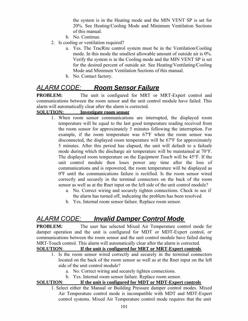
101
the system is in the Heating mode and the MIN VENT SP is set for 20%. See Heating/Cooling Mode and Minimum Ventilation Sections of this manual.
b. No. Continue. 2. Is cooling or ventilation required?
a. Yes. The TracRite control system must be in the Ventilation/Cooling mode. In this mode the smallest allowable amount of outside air is 0%. Verify the system is in the Cooling mode and the MIN VENT SP is set for the desired percent of outside air. See Heating/Ventilating/Cooling Mode and Minimum Ventilation Sections of this manual.
b. No. Contact factory.
ALARM CODE: Room Sensor Failure PROBLEM: The unit is configured for MRT or MRT-Expert control and communications between the room sensor and the unit control module have failed. This alarm will automatically clear after the alarm is corrected. SOLUTION: Investigate room sensor
1. When room sensor communications are interrupted, the displayed room temperature will be equal to the last good temperature reading received from the room sensor for approximately 5 minutes following the interruption. For example, if the room temperature was 67ºF when the room sensor was disconnected, the displayed room temperature will be 67ºF for approximately 5 minutes. After this period has elapsed, the unit will default to a failsafe mode during which the discharge air temperature will be maintained at 70°F. The displayed room temperature on the Equipment Touch will be 45°F. If the unit control module then loses power any time after the loss of communications and is repowered, the room temperature will be displayed as 0ºF until the communications failure is rectified. Is the room sensor wired correctly and securely in the terminal connectors on the back of the room sensor as well as at the Rnet input on the left side of the unit control module?
a. No. Correct wiring and securely tighten connections. Check to see if the alarm has turned off, indicating the problem has been resolved.
b. Yes. Internal room sensor failure. Replace room sensor.
ALARM CODE: Invalid Damper Control Mode PROBLEM: The user has selected Mixed Air Temperature control mode for damper operation and the unit is configured for MDT or MDT-Expert control, or communications between the room sensor and the unit control module have failed during MRT-Touch control. This alarm will automatically clear after the alarm is corrected. SOLUTION: If the unit is configured for MRT or MRT-Expert controls
1. Is the room sensor wired correctly and securely in the terminal connectors located on the back of the room sensor as well as at the Rnet input on the left side of the unit control module?
a. No. Correct wiring and securely tighten connections. b. Yes. Internal room sensor failure. Replace room sensor.
SOLUTION: If the unit is configured for MDT or MDT-Expert controls 1. Select either the Manual or Building Pressure damper control modes. Mixed
Air Temperature control mode is incompatible with MDT and MDT-Expert control systems. Mixed Air Temperature control mode requires that the unit
102
be configured for MRT or MRT-Expert controls and that a room sensor be installed and functioning.
ALARM CODE: Monthly/Quarterly/Yearly Maintenance Reminder (See IOM) PROBLEM: The controller has determined that based on unit runtime, the operator should perform monthly, quarterly, or yearly maintenance functions as outlined in the unit’s Installation, Operation, and Maintenance (IOM) manual. This alarm does not indicate an actual fault or issue with the unit operation and merely serves as a reminder that the unit should be inspected and any relevant maintenance functions should be performed to continue to ensure successful operation of the unit. SOLUTION: If an active maintance reminder alarm is present:
1. Perform monthly, quarterly, or yearly maintenance functions as indicated in the unit’s IOM.
2. Use the Alarms Reset function on the Equipment Touch to reset the alarm.
Glossary
Equipment Touch – A touchscreen display used to change setpoints and monitor the unit’s operation.
Equivalent temperature rise – Simply stated this value is the actual temperature rise generated by the unit at any given time. More precisely stated, it is the quantity of outside air raised to the discharge air temperature, plus, the quantity of return air raised to the discharge air temperature. It is equivalent to the heat actually delivered to the space. The purpose for this in the burner control scheme is to limit the burner’s firing rate, based on the percentage of outside air, and thus the carbon monoxide generated by the unit.
Expressed mathematically it is: Teq = %OA (Tda – Toa) + %RA (Tda – Tra) PID Control or loop – Proportional, Integral, Derivative control, a common control scheme used in modulating HVAC systems.
Remote Control Panel – The remote control panel is a cover plate with one or more of the following controls and indicators: unit enable/remote temperature setpoint pot, remote damper control pot, speed control switch, fill/drain switch, fan on, clogged filter, high speed, low speed, burner on, cool on lights. This cover plate fits on a standard 3 gang electrical switch box.
WebCTRL – A web based graphical user interface, which provides the user access to the unit via the internet.

103
Appendix A 10KΩ Th ermistor Output Curve
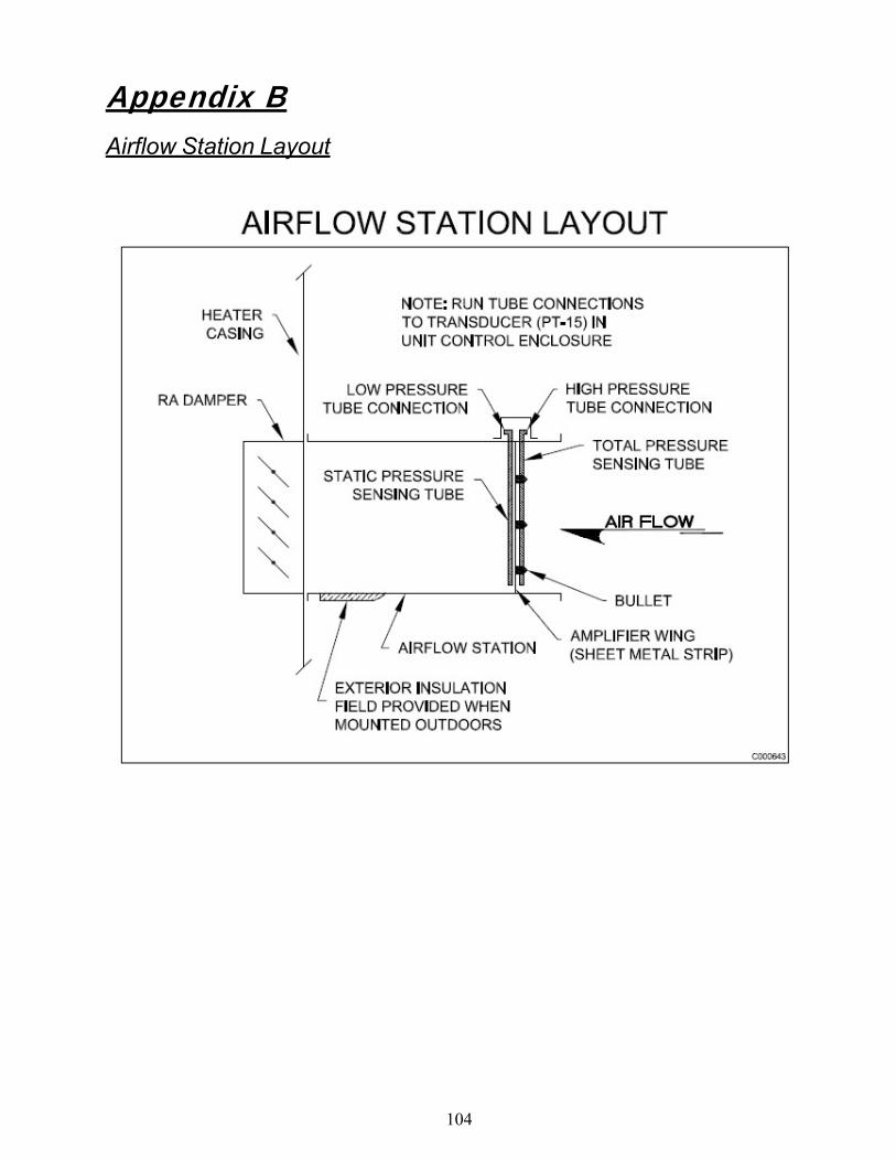
104
Appendix B Airflow Station Layout

105
Appendix C I/O Zone 583 Controller Specifications
POWER REQUIREMENTS 24VAC ± 10%, 20VA
NETWORK COMMUNICATION BACnet (ARCNET and MS/TP), Modbus RTU, or N2 bus at up to 76.8K baud or 156K baud over ARCnet. LonWorks and Ethernet using plug-in communications board.
USER INTERFACE MRT-Touch: modulating room temperature control with intelligent room sensor and Equipment Touch control panel. MDT-Touch: modulating discharge temperature control with Equipment Touch control panel.
MEMORY 1 MB non-volatile battery-backed RAM, 4 MB flash memory, 16-bit memory bus
REALTIME CLOCK Battery-backed to keep time in event of power failure.
TEMPERATURE OPERATING RANGE 0°F to 130°F, 10% to 95% RH non- condensing
INPUTS/OUTPUTS 8 Universal Inputs
Inputs 1 & 2 o Dry, thermistor, 0-5VDC
Inputs 3 – 6 o Dry, thermistor
Inputs 7 & 8 o 1k –10k pot
5 Digital Outputs Relay contacts rated at 1A
Resistive @ 24VAC/VDC LED indication
3 Analog Outputs 0 – 10 VDC
OUTPUT ASSIGNMENTS - ANALOG AO1 Burner gas firing rate 0 – 10 VDC AO2 RA or Mixing Damper Control/ User Configured 0 – 10VDC AO3 Burner gas firing rate
OUTPUT ASSIGNMENTS - DIGITAL DO1 Unit Enable DO2 Burner Enable DO3 Stg 1 Cooling Enable DO4 Stg 2 Cooling Enable DO5 Pilot to Main Flame Sensor Changeover Switch
INPUT ASSIGNMENTS - UNIVERSAL IN1 Pressure Transducer for Building Pressure Control or User Configured IN2 Pressure Transducer for Flow Station IN3 Multiplexed
100% Outside Air/100% Output Flame Failure Alarm Safety Circuit Status Manual/Mixed Air Dmpr Control
IN4 Multiplexed Auxiliary Unit Enable Clogged Filter Fan Status Burner Status
IN5 Outside Air sensor IN6 Discharge Air sensor IN7 Unit Enable/Remote Setpoint IN8 Damper Control
RNET Room Air sensor

106
Appendix D I/O Zone 583 Controller Battery Checkout
The battery on the unit control module retains the controller’s memory in the event of power failure. The 10-year Lithium CR2032 battery provides a minimum of 10,000 hours of data retention during power outages. Remember to check the battery periodically (once a month) to verify that its voltage is approximately 3 VDC.
If the voltage is not at least 3 VDC, replace the battery so that the controller’s program is not lost during a power outage. Loss of the program will require the controller to be shipped back to the factory for reprogramming because the unit will not function without the program.
Make sure the controller is powered any time the battery is removed or the controller’s memory may be lost.
Figure 5 shows the location of the battery on the controller.
Figure 5

107
Appendix E I/O Flex 6126 Controller Specifications
POWER REQUIREMENTS 24VAC ± 10%, 20VA
NETWORK COMMUNICATION BACnet (ARCNET and MS/TP), Modbus RTU, or N2 bus at up to 76.8K baud or 156K baud over ARCnet. LonWorks and Ethernet using plug-in communications board.
USER INTERFACE MRT-Touch: modulating room temperature control with intelligent room sensor and Equipment Touch control panel. MDT-Touch: modulating discharge temperature control with Equipment Touch control panel.
MEMORY 1 MB non-volatile battery-backed RAM, 4 MB flash memory, 16-bit memory bus
REALTIME CLOCK Battery-backed to keep time in event of power failure.
TEMPERATURE OPERATING RANGE -20°F to 140°F, 10% to 95% RH non- condensing
INPUTS/OUTPUTS 12 Universal Inputs
Inputs 1-12 o Dry, thermistor, 0-5VDC
Inputs 1 & 2 o Pulse counting
6 Digital Outputs Relay contacts rated at 5A Resistive
@ 250VAC LED indication
6 Analog Outputs Outputs 1-6
o 0-10 VDC Outputs 1 & 2
o 4-20 mA
OUTPUT ASSIGNMENTS - ANALOG AO1 Burner gas firing rate 0 – 10 VDC AO2 User Configured 0 – 10VDC AO3 Burner air control 0 – 10 VDC AO4 Unassigned AO5 Unassigned AO6 Unassigned
OUTPUT ASSIGNMENTS - DIGITAL DO1 Unit Enable DO2 Burner Enable DO3 Stg 1 Cooling Enable DO4 Stg 2 Cooling Enable DO5 Stg 3 Cooling Enable DO6 Stg 4 Cooling Enable
INPUT ASSIGNMENTS - UNIVERSAL IN1 Outside/Inlet Air Sensor IN2 Discharge Air Sensor IN3 Auxiliary Unit Enable IN4 100% Outside Air Switch IN5 Fan Status IN6 Clogged Filter Status IN7 Safety Circuit Status IN8 Burner Status IN9 Flame Failure IN10 User Input IN11 Unassigned IN12 Unassigned
RNET Room Air sensor

108
Appendix F I/O Flex 6126 Controller Battery Checkout
The battery on the unit control module retains the controller’s memory in the event of power failure. The 10-year Lithium CR2032 battery provides a minimum of 10,000 hours of data retention during power outages. Remember to check the battery periodically (once a month) to verify that its voltage is approximately 3 VDC.
If the voltage is not at least 3 VDC, replace the battery so that the controller’s program is not lost during a power outage. Loss of the program will require the controller to be shipped back to the factory for reprogramming because the unit will not function without the program.
Make sure the controller is powered any time the battery is removed or the controller’s memory may be lost.
Figure 5 shows the location of the battery on the controller.
Figure 5

109
Appendix G
Control System Field Conversion The unit can be converted to a different control system in the field. Locate the unit’s current control system in the “From” column and the new control system in the “To” column that is in the same row as the current control system. Follow the steps outlined in the “New” column to complete the field conversion.
NOTE: Contact the factory for the Equipment Touch Admin password if required and to have the wiring diagram updated when doing a control system field conversion. Failure to do so will result in inaccurate documentation that can complicate possible future troubleshooting efforts.
From To
MRT- Touch
MDT-Touch 1. On the Equipment Touch, navigate to Home > Menu > Setup. Change the
Control System parameter to “MDT”. 2. Navigate to the Home > Menu > Setpoints to configure the appropriate
setpoints for the MDT-Touch control system. 3. Optionally disconnect the room sensor. Leaving the room sensor connected
will not affect unit operation in when the MDT-Touch control system is active.
MDT- Touch
MRT-Touch 1. Mount a room sensor and wire it to the Rnet terminals on the controller. 2. On the Equipment Touch, navigate to Home > Menu > Setup. Change the
Control System parameter to “MRT”. 3. Navigate to the Home > Menu > Setpoints to configure the appropriate
setpoints for the MRT-Touch control system.
Appendix H Heating and Cooling Design Temperatures Locate the city closest to where the unit is installed and change the heating and cooling design temperature setpoints on the Equipment Touch to match the values in the table below for that particular city.
State City Heating Design
TemperatureCooling Design Temperature
AL Birmingham 21 94 AL Hunstville 16 96 AL Mobile 29 93 AL Montgomery 25 95 AK Anchorage -18 68 AK Fairbanks -47 78 AK Juneau 1 70 AK Nome -27 62

110
AZ Flagstaff 4 92 AZ Phoenix 34 107 AZ Tucson 32 102 AZ Yuma 39 109 AR Fort Smith 17 98 AR Little Rock 20 96 AR Texarkana 23 96 CA Fresno 30 100 CA Long Beach 43 80 CA Los Angeles 40 89 CA Oakland 36 80 CA Sacramento 32 98 CA San Diego 44 80 CA San Francisco 40 71 CO Alamosa -16 82 CO Colorado Springs 2 88 CO Denver 1 91 CO Grand Junction 7 94 CO Pueblo 0 95 CT Bridgeport 9 84 CT Hartford 7 88 CT New Haven 7 84 DE Wilmington 14 89 DC Washington 17 91 FL Daytona 35 90 FL Fort Myers 44 92 FL Jacksonville 32 94 FL Key West 57 90 FL Miami 47 90 FL Orlando 38 93 FL Pensacola 29 93 FL Tallahassee 30 92 FL Tampa 40 91 FL West Palm Beach 45 91 GA Athens 22 92 GA Atlanta 22 92 GA Augusta 23 95 GA Columbus 24 93 GA Macon 25 93 GA Rome 22 93 GA Savannah 27 93 HI Hilo 62 83 HI Honolulu 63 86 ID Boise 10 94 ID Lewiston 6 93 ID Pocatello -1 91 IL Chicago 2 91 IL Moline -4 91 IL Peoria -4 89

111
IL Rockford -4 89 IL Springfield 2 92 IN Evansville 9 93 IN Fort Wayne 1 89 IN Indianapolis 2 90 IN South Bend 1 89 IA Burlington -3 91 IA Des Moines -5 91 IA Dubuque -7 88 IA Sioux City -7 92 IA Waterloo -10 89 KS Dodge City 5 97 KS Goodland 0 96 KS Topeka 4 96 KS Wichita 7 98 KY Covington 6 90 KY Lexington 8 91 KY Louisville 10 93 LA Alexandria 27 94 LA Baton Rouge 29 93 LA Lake Charles 31 93 LA New Orleans 33 92 LA Shreveport 25 96 ME Caribou -13 81 ME Portland -1 84 MD Baltimore 17 89 MD Frederick 12 91 MA Boston 9 88 MA Pittsfield -3 84 MA Worcester 4 84 MI Alpena -6 85 MI Detroit 6 88 MI Escanaba -7 83 MI Flint 1 87 MI Grand Rapids 5 88 MI Lansing 1 87 MI Marquette -8 81 MI Muskegon 6 84 MI Sault St. Marie -8 81 MN Duluth -16 82 MN Minneapolis -12 89 MN Rochester -12 87 MS Jackson 25 95 MS Meridian 23 95 MS Vicksburg 26 95 MO Columbia 4 94 MO Kansas City 6 96 MO St. Joseph 2 93 MO St. Louis 8 94

112
MO Springfield 9 93 MT Billings -10 91 MT Great Falls -15 88 MT Helena -16 88 MT Missoula -16 88 NE Grand Island -3 94 NE Lincoln -2 95 NE Norfolk -4 93 NE North Platte -4 94 NE Omaha -3 91 NE Scottsbluff -3 92 NV Elko -2 92 NV Ely -4 87 NV Las Vegas 28 106 NV Reno 10 92 NV Winnemucca 3 94 NH Concord -3 87 NJ Atlantic City 13 89 NJ Newark 14 91 NJ Trenton 14 88 NM Albuquerque 16 94 NM Raton 1 89 NM Roswell 18 98 NM Silver City 10 94 NY Albany 1 88 NY Binghamton 1 83 NY Buffalo 6 85 NY New York City 15 89 NY Rochester 5 88 NY Schenectady 1 87 NY Syracuse 2 87 NC Charlotte 22 93 NC Greensboro 18 91 NC Raleigh 20 92 NC Winston-Salem 20 91 ND Bismarck -19 91 ND Devils Lake -21 88 ND Fargo -18 89 ND Williston -21 88 OH Akron-Canton 6 86 OH Cincinnati 6 90 OH Cleveland 5 88 OH Columbus 5 90 OH Dayton 4 89 OH Mansfield 5 87 OH Sandusky 6 91 OH Toledo 1 88 OH Youngstown 4 86 OK Oklahoma City 13 97

113
OK Tulsa 13 98 OR Eugene 22 89 OR Medford 23 94 OR Portland 24 86 OR Salem 23 88 PA Allentown 9 88 PA Erie 9 85 PA Harrisburg 11 91 PA Philadelphia 14 90 PA Pittsburgh 7 88 PA Reading 13 89 PA Scranton 5 87 PA Williamsport 7 89 RI Providence 9 86 SC Charleston 28 92 SC Columbia 24 95 SD Huron -14 93 SD Rapid City -7 92 SD Sioux Falls -11 91 TN Bristol 14 89 TN Chattanooga 18 93 TN Knoxville 19 92 TN Memphis 18 95 TN Nashville 14 94 TX Abilene 20 99 TX Austin 28 98 TX Dallas 22 100 TX El Paso 24 98 TX Houston 32 94 TX Midland 21 98 TX San Angelo 22 99 TX San Antonio 30 97 TX Waco 26 99 TX Wichita Falls 18 101 UT Salt Lake City 8 95 VT Burlington -7 85 VA Lynchburg 16 90 VA Norfolk 22 91 VA Richmond 17 92 VA Roanoke 16 91 WA Olympia 22 83 WA Seattle 27 82 WA Spokane 2 90 WV Charleston 11 90 WV Elkins 6 84 WV Huntington 10 91 WV Parkersburg 11 90 WI Green Bay -9 85 WI La Crosse -9 88
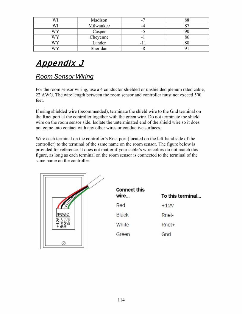
114
WI Madison -7 88 WI Milwaukee -4 87 WY Casper -5 90 WY Cheyenne -1 86 WY Lander -11 88 WY Sheridan -8 91
Appendix J Room Sensor Wiring
For the room sensor wiring, use a 4 conductor shielded or unshielded plenum rated cable, 22 AWG. The wire length between the room sensor and controller must not exceed 500 feet.
If using shielded wire (recommended), terminate the shield wire to the Gnd terminal on the Rnet port at the controller together with the green wire. Do not terminate the shield wire on the room sensor side. Isolate the unterminated end of the shield wire so it does not come into contact with any other wires or conductive surfaces.
Wire each terminal on the controller’s Rnet port (located on the left-hand side of the controller) to the terminal of the same name on the room sensor. The figure below is provided for reference. It does not matter if your cable’s wire colors do not match this figure, as long as each terminal on the room sensor is connected to the terminal of the same name on the controller.

115
Appendix K Equipment Touch Wiring
Portable / Using the Terminal Plug The Equipment Touch is supplied from the factory with a 10-foot cable with a terminal plug on one end. The other end of the cable is connected to the terminals on the Equipment Touch. To use the Equipment Touch, plug the terminal plug on the cable into the appropriate terminal blocks in the unit’s main control panel.
For your convenience, two of the terminal blocks are pre-wired at the factory to the Rnet+ and Rnet- terminals on the controller. The other two terminal blocks are pre-wired at the factory to the 24 VAC power source in the main control panel (typically control transformer TR-05).
Plugging the terminal plug into the four terminal blocks completes the connection between the Equipment Touch (shown on the left-hand side of the terminal plug in the figure below) and the controller and power supply/transformer (shown on the right-hand side of the terminal plug in the figure below). Refer to the figure below for a visual representation of these connections.

116
Hard-Wired / No Terminal Plug To hard-wire the Equipment Touch to the controller (eliminating the terminal plug):
Rnet+ on the Equipment Touch must be connected to the Rnet+ terminal on the controller.
Rnet- on the Equipment Touch must be connected to the Rnet- terminal on the controller.
24V Gnd on the Equipment Touch must be connected to the 24 VAC source’s ground (typically terminal number 202 on the unit’s wiring diagram, refer to the unit’s wiring diagram to verify).
24V + on the Equipment Touch must be connected to the 24 VAC source hot (typically terminal number 201 on the unit’s wiring diagram, refer to the unit’s wiring diagram to verify).

117
Notes Notes

118
Notes Notes

119
Notes Notes

120
4830 Transport Drive, Dallas, TX 75247
Phone: 214-638-6010 www.tempriteheating.com