temporal adaptive algorithm for trac-bf1/nem/cobra-tf coupled calculations in bwr safety analysis
TRANSCRIPT

Temporal adaptive algorithm forTRAC-BF1/NEM/COBRA-TF coupledcalculations in BWR safety analysis
Jorge Solı́s, Maria N. Avramova, Kostadin N. Ivanov*
Department of Mechanical and Nuclear Engineering, Nuclear Engineering Program, The Pennsylvania State
University, 230 Reber Building, University Park, PA 16802, USA
Received 25 February 2002; accepted 20 March 2002
Abstract
A temporal adaptive algorithm was developed to perform the synchronization and optimi-zation of the performance of TRAC-BF1/NEM/COBRA-TF three-dimensional neutron/
thermal-hydraulics sub-channel analysis coupled code system. The multi-level couplingscheme for time synchronization of the TRAC-BF1/NEM and COBRA-TF under PVM isdeveloped considering the different time-step selection algorithms of TRAC-BF1, NEM and
COBRA-TF codes. The developed methodology allows one to synchronize the codes in timewithout doing significant code modifications to the time-step selection logic of the involvedcodes. The advantage of this approach is that COBRA-TF can capture the nature of a giventransient, without losing any time-dependent data. Results for steady state and transient cal-
culations that show how the implemented temporal adaptive algorithm works are presented.In addition selected results are presented to illustrate dynamic behavior and the type ofthermal-hydraulic boundary conditions provided by the system code.# 2002 Elsevier Science
Ltd. All rights reserved.
1. Introduction
With the continuous progress of computer technology the use of coupled three-dimensional (3D) neutron kinetics/thermal-hydraulic system codes is becomingincreasingly common for applications that involve calculations to model moreaccurately not only reactivity initiated accidents (RIA), but also typical reactor
Annals of Nuclear Energy 29 (2002) 2127–2141
www.elsevier.com/locate/anucene
0306-4549/02/$ - see front matter # 2002 Elsevier Science Ltd. All rights reserved.
PI I : S0306-4549(02 )00040 -3
* Corresponding author. Tel.: +1-814-865-0040; fax: +1-814-865-8499.
E-mail address: [email protected] (K.N. Ivanov).

operational transient (e.g., turbine trip, load rejection). These computational pro-grams, which are often called ‘‘best-estimate’’ analysis tools, describe more realisti-cally the local core effects and coupled reactor core/plant dynamics interactions, andsubsequently forecast safety margins more accurately. The recent 3D nodal neutronkinetic models usually employ planar meshes that are of the size of the fuel assem-blies (or part of assemblies). However, the accident consequences (fuel rod enthalpy,departure of nucleate boiling—DNB, or peak cladding temperature) need to beevaluated in terms of a single fuel rod (pin) response rather than assembly (bundle)average response.The modeling capabilities of these best-estimate system coupled codes must befurther extended to include a pin power reconstruction scheme, coupled to sub-channel model, in order to obtain the transient fuel rod response. This paper dis-cuses the developed adaptive algorithm necessary for temporal coupling of thesemultilevel calculations.TRAC-BF1 and NEM are coupled by using parallel virtual machine (PVM)environment (Geist et al., 1994). The numerical scheme of the PVM coupling is asemi-implicit scheme for the calculated power (Lu, 1997). In most cases (especiallyduring steady state calculation), the number of times the three-dimensional (3D)kinetics calculations performed can be optimized to speedup the calculation. Forthis purpose, a multiple time step marching scheme is implemented in TRAC-BF1/NEM calculation. This scheme allows TRAC-BF1 solution to march several stepswhile NEM only marched one large time step. For the coupled TRAC-BF1/NEMcode a 3D kinetics variable time step algorithm has been developed and imple-mented together with a meshing scheme with the thermal-hydraulic time step
Nomenclature
L1 normL2 normT time" error
SubscriptsG globalL localmax maximummin minimum
SuperscriptsK time step number
2128 J. Solı́s et al. / Annals of Nuclear Energy 29 (2002) 2127–2141

algorithm. The kinetics algorithm has an automatic time step control procedure thatmonitors the temporal changes (global–power and local–neutron flux) during agiven time and adjusts the time size automatically. For any successive time integra-tion step, it is required that the maximum scaled change be smaller than a user-specified tolerance " ("G—global, set up to limit global power change to 1% per timestep and "L—local, set up to limit local flux change to 10% per time step). Theglobal and local relative changes are calculated by evaluating the first derivative intime of the monitored variables (power and flux). The rate of accumulation of theglobal change (d"G/dt) is calculated in the L2 norm while the rate of accumulation oflocal change is calculated in an L1 norm. The required kinetics time step size isdetermined as follows:
TKG ¼"Gd"Gdt
ð1Þ
TKL ¼"Ld"Ldt
ð2Þ
TKestimate ¼ min TKG;TKL
� �> TKmin ð3Þ
TKmin—equal to the thermal-hydraulic time step size.
TKfinal ¼ min TKestimate;TKmax
� �ð4Þ
TKmax—specified by the user.In order to provide best-estimate analysis of local safety parameters, the COBRA-TF thermal-hydraulics sub-channel analysis code (Solı́s, 2000) is coupled to theTRAC-BF1/NEM code using also PVM. Since TRAC-BF1/NEM and COBRA-TFcodes use their own algorithm to select the time-step size during a given calculation,some techniques have to be implemented in order to have a good synchronization ofthe codes when marching on the same time scale. COBRA-TF has more restrictiveconvergence criteria as compared to the system TRAC-BF1 code. There is a singleinput parameter in COBRA-TF, which could be used for relaxing the time-step size.This parameter is the so-called outer iteration convergence criterion. Suggestedvalue of 0.001 is given in the COBRA-TF User’s Manual (Paik et al., 1985). Theother parameters used for iteration control are the maximum number of outeriterations and the maximum number of vessel iterations. Table 1 shows a compar-ison of the iteration control parameters between the two codes. Table 2 shows acomparison of the relevant thermal-hydraulic parameters evaluated during the time-step calculation. There are in the COBRA-TF time-step selection algorithm twoother parameters that are also checked out during the calculation of a new pro-spective time-step size. These are the Courant limit and the vessel error limit. Thesetwo parameters combined with pressure and void fraction are used to come up with
J. Solı́s et al. / Annals of Nuclear Energy 29 (2002) 2127–2141 2129

the total error limit. Since COBRA-TF has been designed as a transient code, it doesnot have a convergence criterion for steady state calculation. The selected approachis based on the principle that the coupled synchronization and optimization has tobe achieved without affecting the time-step selection logic of the coupled codes. Thisapproach is presented in detail in the next section.
2. TRAC-BF1/NEM/PVM/COBRA-TF synchronization in time
The approach used for synchronizing the codes is illustrated in Fig. 1. This figureshows that a hot-channel analysis option is added as a second level coupling in thePVM environment to the normal TRAC-BF1/NEM calculation scheme (first levelcoupling). The hot-channel calculation is started by the NEM code under the PVMenvironment. The transfer of data among the codes is performed using the PVMdata transfer capabilities. The TRAC-BF1/NEM code sends timepvm to COBRA-TF, which is the time-step just selected for a given neutronic/thermal-hydraulic cal-culation. The number of TRAC-BF1/NEM time-step calculations before spawningCOBRA-TF is left to the user’s criteria. Typically two time-steps is an acceptablechoice. For the case of a transient calculation, not much change (if any) will be‘‘missed’’ by COBRA-TF, since at the beginning of the transient calculation;TRAC-BF1/NEM time-step size is usually very small. This very short initializationtime should be enough, assuming that an acceptable steady state calculation was
Table 2
Thermal-hydraulic parameters evaluated during time-step calculation
TRAC-BF1 COBRA-TF
Pressure Pressure
Void fraction Void fraction
Liquid velocity Not available
Vapor velocity Not available
Liquid temperature Not available
Vapor temperature Not available
System metal temperature Not available
Rod temperature Not available
Table 1
Iteration control
TRAC-BF1 COBRA-TF
Convergence criterion for outer iteration Convergence criterion for outer iteration
Convergence criterion for vessel iteration Not available
Convergence criterion for steady state Not available
Maximum number of outer iterations Maximum number of outer iterations
Maximum number of vessel iterations Maximum number of vessel iterations
2130 J. Solı́s et al. / Annals of Nuclear Energy 29 (2002) 2127–2141

achieved during the TRAC-BF1/NEM initialization step. The TRAC-BF1/NEMmultiple time step marching scheme is shown in Fig. 2. This figure also shows howCOBRA-TF is marching in time. Fig. 3 shows the coupled code where a one-to-onetime step calculation is performed by TRAC-BF1 and NEM. The COBRA-TF cal-culation sequence is shown as well.
Fig. 2. Multiple time step algorithm.
Fig. 1. TRAC-BF1/NEM/PVM/COBRA-TF time synchronization approach.
J. Solı́s et al. / Annals of Nuclear Energy 29 (2002) 2127–2141 2131

In summary, the synchronization algorithm proceeds as follows. TRAC-BF1/NEM is started first under PVM environment. After some time-steps in the calcu-lation, COBRA-TF code is initialized. The above procedure will allow one to haveall the hot-channel parameters (thermal-hydraulic boundary conditions, pin powerreconstruction, and etc.) available to initialize the hot-channel analysis code. At thisstep, COBRA-TF has started under PVM environment and some of the input dataare replaced with data coming through PVM. Most important, some of the time-step cards given as input are replaced during this initialization. The end of the timedomain given is the time-step size sent by TRAC-BF1/NEM (the problem calcula-tion time is accumulated using this time step). In other words, the system code takescontrol of COBRA-TF time-step cards. Typically, it will take several COBRA-TF
Fig. 3. Base coupling scheme.
Fig. 4. Steady-state calculation from 0 to 500 time-steps.
2132 J. Solı́s et al. / Annals of Nuclear Energy 29 (2002) 2127–2141

time steps to complete the calculation of a single TRAC-BF1/NEM time-step. Itdepends on the dynamic of the transient. At some point, the time-step size of bothcodes, almost matches each other.
2.1. Steady state case
An example of the time synchronization achieved for the coupled codes is pre-sented in Figs. 4 and 5 for a steady state calculation. Fig. 4 shows the results fromzero to five hundred time-steps. It can be seen in this figure that at the beginning ofthe calculation, COBRA-TF takes a number of calculations to reach the coupledcode calculation time. As the calculation proceeds, thermal-hydraulic distributionbegins to reach more stable values, as it can be seen in Fig. 5 from 500 to 1000 timesteps. At this point, the number of time-steps taken by COBRA-TF to complete acoupled code time-step decreases, making a more tight synchronization in timebetween the codes. For illustration purposes, a comparison between COBRA-TFtime step sizes vs. TRAC-BF1/NEM is presented in Fig. 6. It can be seen in thisfigure that TRAC-BF1 reaches a point where the time-step size remains constant forthe rest of the calculation. On the other hand, COBRA-TF time-step size is con-tinuously varying.Since the COBRA-TF code was designed as a transient sub-channel analysis code,coupling with the system code is more challenging for steady-state calculations. Inreality, during steady-state calculation, COBRA-TF is performing a ‘‘null’’ transient(quasi steady-state calculation) rather than a steady-state one. After achieving con-vergence of the coupled code for the steady state case, dump and restart options are
Fig. 5. Steady-state calculation from 500 to 1000 time-steps.
J. Solı́s et al. / Annals of Nuclear Energy 29 (2002) 2127–2141 2133

activated for the both TRAC-BF1/NEM and COBRA-TF for performing furtherthe transient analysis.COBRA-TF modeling features were improved to allow for a certain fraction ofgenerated heat to be released in the coolant directly. This fraction is a users’ speci-fied input parameter.In the last version of COBRA-TF code, a restart capability is introduced. TheDUMP/RESTART option makes the code possible to perform long transient cal-culations efficiently. Long transient modeling large systems can required many hoursof computer time to exist. The DUMP/RESTART capability allows the user tocalculate the transient as a series of shorter calculations, each restarting at the pointthe previous one left off. The user can then monitor the calculation as it progressesand minimize wasted computer time resulting from input errors and computersystem failures.
2.2. Transient case
Results of a transient calculation are shown in Figs. 7–11. Fig. 8 shows the cal-culation from 500 time-steps to 1500. It can be seen here, that in the last part of thetransient, COBRA-TF time-step size increases, therefore, taking a lower number tocomplete a system code time-step. Fig. 7, shows the range from 1 time-step to 500.The little horizontal lines shown here are the TRAC-BF1/NEM time-steps, which iskept constant during a COBRA-TF calculation.
Fig. 6. Time-step size comparison for steady-state calculation.
2134 J. Solı́s et al. / Annals of Nuclear Energy 29 (2002) 2127–2141

Since the example transient is very mild in terms of dynamic response, there is justa small difference between the number of time-steps during steady state and transientcalculation. This is shown in Fig. 9, where it can be seen that at the beginning of thecalculations, the time-step sizes match for steady state and transient calculation. Fig. 10compares the time-step step size for COBRA-TF quasi steady state and transient calcu-lation. Fig. 11 shows a comparison of the time-step size between the codes. COBRA-TFtime step size is always smaller than the time-step taken by the system code.
Fig. 8. Transient calculation from 500 to 1500 time-steps.
Fig. 7. Transient calculation from 0 to 500 time-steps.
J. Solı́s et al. / Annals of Nuclear Energy 29 (2002) 2127–2141 2135

3. Dynamic response testing of the refined hot-channel analysis module
The stand-alone version of COBRA-TF thermal-hydraulic hot channel analysiscode accounts for transient response through the use of forcing functions. There area number of these forcing functions that can be implemented for a given calculation.For instance, at the start of a transient simulation, fixed axial power profile tablesare given as part of the thermal-hydraulic hot channel analysis calculation. At somepoint in the transient, the power forcing functions are activated and the initial powerprofile is modified according to the value of the power function factor specified inthe input data. The disadvantage of this procedure is that the user should know inadvance exactly where in time power is going to vary, and how much the magnitudeof this variation is going to be. This approach may be used for design purposes, butit does not really reproduces the actual dynamic behavior.Coupling the hot-channel analysis code with the TRAC-BF1/NEM code underPVM environment removes the need of having power forcing functions tables at thestart of a given calculation. Power profiles of the modeled fuel rods are provided on-line through the use of the pin power reconstruction of the NEM code. For the caseof thermal-hydraulic boundary conditions, forcing functions can also be specified torepresent the transient simulation. In some cases, it is possible that the thermal-hydraulic boundary conditions do not vary too much during a given calculation.The new multi-level coupling capability captured well this variation in a best-esti-mate manner by making use of the available thermal-hydraulic information comingfrom the system code. This information is passed through PVM for each time step.
Fig. 9. Comparison of steady-state vs. transient case.
2136 J. Solı́s et al. / Annals of Nuclear Energy 29 (2002) 2127–2141
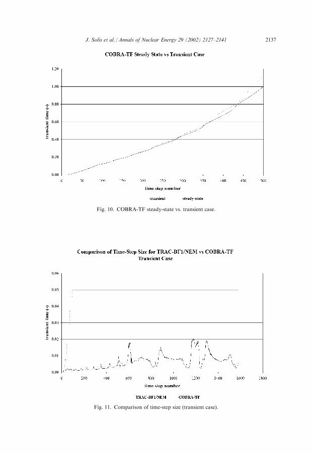
Fig. 10. COBRA-TF steady-state vs. transient case.
Fig. 11. Comparison of time-step size (transient case).
J. Solı́s et al. / Annals of Nuclear Energy 29 (2002) 2127–2141 2137

Fig. 12. Hot channel inlet enthalpy.
Fig. 13. Hot channel outlet enthalpy.
2138 J. Solı́s et al. / Annals of Nuclear Energy 29 (2002) 2127–2141
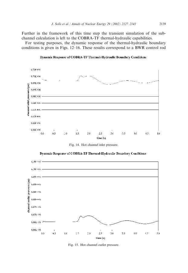
Further in the framework of this time step the transient simulation of the sub-channel calculation is left to the COBRA-TF thermal-hydraulic capabilities.For testing purposes, the dynamic response of the thermal-hydraulic boundaryconditions is given in Figs. 12–16. These results correspond to a BWR control rod
Fig. 14. Hot channel inlet pressure.
Fig. 15. Hot channel outlet pressure.
J. Solı́s et al. / Annals of Nuclear Energy 29 (2002) 2127–2141 2139

drop simulation. Fig. 12 shows the channel inlet enthalpy, which basically remainsconstant during the transient calculation, except for a small variation that is causedby the total reactor thermal power rise. Since, the core flow is very small (approxi-mately corresponding to natural circulation conditions), it takes some time until thepower rise is felt at the reactor lower plenum and then at the core inlet. Fig. 13shows the channel outlet enthalpy—the heat up of the coolant causes a large changecompared to the initial value. Figs. 14 and 15 show the channel inlet and outletpressure respectively. Little change is noticed as compared to the channel inletenthalpy. Fig. 16 shows the channel inlet mass flow rate where also some variation isnoticed, especially during the big power rise. In general, the expected dynamic var-iation is going to depend on the dynamics of the transient being simulated. With theabove example, the dynamic capability of the boundary conditions is demonstratedand tested. For more involved system transients these changes will be more sig-nificant. It will be very difficult to model these changes with the stand-aloneCOBRA-TF code using forcing functions. In addition, the transient behavior shouldbe known in advance. The multi-level coupled TRAC-BF1/NEM/COBRA-TF codesystem provides on-line best-estimate transient simulation on both global and locallevels.
4. Conclusions
The temporal adaptive algorithm for time synchronization of the TRAC-BF1/NEM and COBRA-TF under PVM is designed taking into account the different
Fig. 16. Hot channel mass flow rate.
2140 J. Solı́s et al. / Annals of Nuclear Energy 29 (2002) 2127–2141

time-step selection algorithms of both codes. This approach allows one to synchro-nize the codes in time without doing significant code modifications to the time-stepselection logic of both codes. The advantage of this approach is that COBRA-TFcan capture the time-dependent nature of a given transient without losing any time-dependent data. One shortcoming is that since COBRA-TF time-step is usuallysmaller, the computation time increases for mild transients where the time-step sizeof the system code increases. An optimization procedure is being developed directedto enhance the current algorithm for such cases. For very rapid transients, thisshortcoming is not important, since the time-step size of both codes is very similar insize. The new capability can be used for performing a sub-channel analysis thatbetter reflects the dynamic nature of the boundary conditions imposed to the sub-channel model. The time-dependent nature of the boundary conditions was demon-strated when performing a transient simulation using the TRAC-BF1/NEM systemcode and the sub-channel analysis code COBRA-TF coupled through the use ofPVM environment.
References
Geist, A., et al., 1994. PVM Parallel Virtual Machine, A User’s Guide and Tutorial for Networked
Parallel Computing. The MIT Press.
Lu, S., 1997. GE Simplified Boiling Water Reactor Stability Analysis in Time Domain. PhD thesis, The
Pennsylvania State University.
Paik, C.Y., Hochreiter, L.E., Kelly, J.M., Kohrt, R.J., 1985. Analysis of Flecht Seaset 163-Rod Blocked
Bundle Data Using COBRA-TF, NUREG/CR-4166, EPRI NP-4111, WCAP-10375.
Solı́s, J., 2000. Refined Multi-Level Methodology in Parallel Computing Environment for BWR RIA
Analysis. PhD thesis, The Pennsylvania State University.
J. Solı́s et al. / Annals of Nuclear Energy 29 (2002) 2127–2141 2141