temperature control systems - pcs company temperature control... · temperature controller -...
TRANSCRIPT

Phone: 800-521-0546 E-mail: [email protected] Fax: 800-505-3299www.pcs-company.com
K1
TEM
PER
ATU
RE
CO
NTR
OL
SYST
EMS
TEM
PER
ATU
RE
CO
NTR
OL
SYST
EMS
Accessories.................................................................................................................K26 Cables - Mold Power & Thermocouple Conversion OEM Style..................................K22
Cables - Mold Power & Thermocouple for Onyx System..............................................K7
Cables - Mold Power & Thermocouple.......................................................................K14
Connectors - Mold OEM Style....................................................................................K23
Connectors - Mold.......................................................................................................K15
Module - Mainframe Alarm..........................................................................................K13
Module - VC-M 15 Amp.................................................................................................K8 Module - VC-MP 15 Amp..............................................................................................K9
Product Family Comparison..........................................................................................K3
Replacement Parts.....................................................................................................K24
Temperature Controller - Modular Guide.....................................................................K11
Temperature Controller - Modular Mainframe Systems Configuration........................K13
Temperature Controller - Onyx System.........................................................................K4
Temperature Controller - Single Zone Horizontal........................................................K10
Temperature Controller - Visions 3000/2.0 System....................................................K29 Temperature Controller - Visions 3000/2.0 WaterFlow/Smart Manifold......................K34
Terminal Mounting Boxes - Combination OEM Style..................................................K21
Terminal Mounting Boxes - Combination....................................................................K18
Terminal Mounting Boxes - Pre-Wired OEM Style......................................................K19
Terminal Mounting Boxes - Pre-wired.........................................................................K17
TEMPERATURE CONTROL SYSTEMS
Phone: 800-521-0546 E-mail: [email protected] Fax: 800-505-3299www.pcs-company.com
K2TE
MPE
RAT
UR
E C
ON
TRO
L SY
STEM
STE
MPE
RAT
UR
E C
ON
TRO
L SY
STEM
S
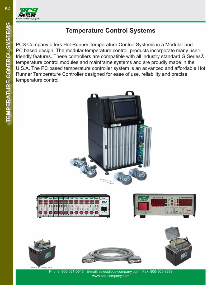
Temperature Control Systems
PCS Company offers Hot Runner Temperature Control Systems in a Modular and PC based design. The modular temperature controll products incorporate many user-friendly features. These controllers are compatible with all industry standard G Series® temperature control modules and mainframe systems and are proudly made in the U.S.A. The PC based temperature controller system is an advanced and affordable Hot Runner Temperature Controller designed for ease of use, reliability and precise temperature control.
Phone: 800-521-0546 E-mail: [email protected] Fax: 800-505-3299www.pcs-company.com
K3
TEM
PER
ATU
RE
CO
NTR
OL
SYST
EMS
TEM
PER
ATU
RE
CO
NTR
OL
SYST
EMS
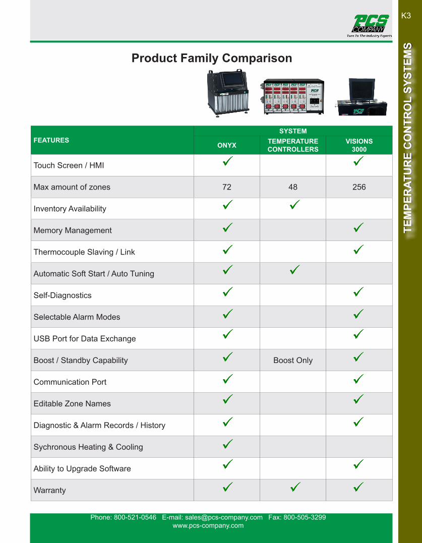
FEATURESSYSTEM
ONYX TEMPERATURECONTROLLERS
VISIONS3000
Touch Screen / HMI
Max amount of zones 72 48 256
Inventory Availability
Memory Management
Thermocouple Slaving / Link
Automatic Soft Start / Auto Tuning
Self-Diagnostics
Selectable Alarm Modes
USB Port for Data Exchange
Boost / Standby Capability Boost Only
Communication Port
Editable Zone Names
Diagnostic & Alarm Records / History
Sychronous Heating & Cooling
Ability to Upgrade Software
Warranty
Product Family Comparison

Phone: 800-521-0546 E-mail: [email protected] Fax: 800-505-3299www.pcs-company.com
K4TE
MPE
RAT
UR
E C
ON
TRO
L SY
STEM
STE
MPE
RAT
UR
E C
ON
TRO
L SY
STEM
S
• Compact, robust cabinet design
• HMI - 7” Adjustable touchscreen display,
• Auto tuning and soft start
• Programmable Boost
• Programmable Stand-by mode
• Synchronous Heating and Cooling
• Caster wheels included
• Supplied with 10’ input power cable, wired 240v 3 phase in cabinet
• Editable zone names
• Memory management for multiple molds
• USB port for import and export of data and software updates
• Communication alarm board accepts external alarm from
24v DC signal for optional standby & shut down controls
• Multilingual options to include Spanish
• Warranty- 2 year; Human Machine Interface (HMI-screen) 1 year
CATALOG NO. ZONES DIMENSIONS WEIGHT SHIPPING WEIGHT REPLACEMENT HMI SCREEN
TC1200 12 13” x 15” x 16.5” 48 lbs. 66 lbs.HMI51
(7” HMI)TC2400 24 13” x 15” x 22.5” 65 lbs. 85 lbs.TC3600 36 13” x 15” x 28.6” 90 lbs. 156 lbs.TC4800 48 13” x 20.4” x 40.5” 167 lbs. 234 lbs.
HMI52(10.4” HMI)TC6000 60 13” x 20.4” x 46.6” 194 lbs. 264 lbs.
TC7200 72 13” x 20.4” x 52.7” 220 lbs. 298 lbs.
Onyx System Features
CATALOG NO. OPTIONAL ITEM TRANSFORMER KIT
TCFS Onyx Floor Stand Not IncludedTCFS-09 Onyx Floor Stand - 9KVA Transformer Kit TK91AG TCFS-15 Onyx Floor Stand - 15KVA Transformer Kit TK151AGTCFS-30 Onyx Floor Stand - 30KVA Transformer Kit TK301AG
Onyx Floor Stand Options
TC2400
TCFS-15

Phone: 800-521-0546 E-mail: [email protected] Fax: 800-505-3299www.pcs-company.com
K5
TEM
PER
ATU
RE
CO
NTR
OL
SYST
EMS
TEM
PER
ATU
RE
CO
NTR
OL
SYST
EMS
SPECIFICATIONSUser Interface Full-color LCD HMI touch screen displayDisplay Size (Inches) Adjustable 7” TFT SVGA LCDTemperature Control Accuracy ±0.25%FSCalibration Accuracy ±0.25%FSControl Algorithm Adaptive PID with auto temperature tuningTemperature Scale °F or °C Software SelectableThermocouple Type J/K Softwared selectableOperating Temperature Range 32-999°F / 0-600°COutput Voltage 3450W, 230Vac/15A (per zone)Supply Voltage Default 240V /three phase with optional wiringFrequency 50/60HzAmbient Temperature Range 14-122°F / -10-50°COperating Humidity 0-80%RH non-condensingAnomaly Detection T/C, Heater, Triac, FusesPower Control Triangulated control technology - Power optimization
Communication Mode USB port for import/export, job saves, and software updates, RS-485 (Standard MODBUS, Isolated)
Alarm Output & Anomoly Detection
Thermocouple: Short / Break / Reverse Heater: Short / Break / Overload TRIAC: Short, Fuse Open Circuit
LED Indicators Output, Alarm, Fuse Break, Communication, OVSSecurity Yes, three management lockout levelsSoft-Start with Auto-Tune YesSynchronous heating and cooling Yes, software selectableMulti language Support Yes, English and ChineseWarranty 2 year; Human machine interface (HMI-screen) 1 year
Onyx Controller Specifications
TC1200

Phone: 800-521-0546 E-mail: [email protected] Fax: 800-505-3299www.pcs-company.com
K6TE
MPE
RAT
UR
E C
ON
TRO
L SY
STEM
STE
MPE
RAT
UR
E C
ON
TRO
L SY
STEM
S
Onyx Product Diagnostics & Dimensions
CATALOG NO. REPLACEMENT ITEMTC52-MDL Onyx Controller Board (2 Zone)TC52-BUS BUS BoardTC52-ALM Alarm BoardTC52-OVP Over Voltage Protection Board

Phone: 800-521-0546 E-mail: [email protected] Fax: 800-505-3299www.pcs-company.com
K7
TEM
PER
ATU
RE
CO
NTR
OL
SYST
EMS
TEM
PER
ATU
RE
CO
NTR
OL
SYST
EMS
CATALOGNO.
NUMBER OF ZONES (MAX.)
FROM 15 amp MAINFRAMES(s) TO MOLD END LENGTH
VC-5PC10 5 5, 8, 12 zone VC-5MPC 10 ft.
VC-8PC10 8 8, 12 zone VC-8MPC 10 ft.
VC-12PC10 12 12 zone VC-12MPC 10 ft.
VC-5PC 5 5, 8, 12 zone VC-5MPC 15 ft.
VC-8PC 8 8, 12 zone VC-8MPC 15 ft.
VC-12PC 12 12 zone VC-12MPC 15 ft.
VC-5PC20 5 5, 8, 12 zone VC-5MPC 20 ft.
VC-8PC20 8 8, 12 zone VC-8MPC 20 ft.
VC-12PC20 12 12 zone VC-12MPC 20 ft.
Mold Power Cables
Thermocouple Cables
Thermocouple Cables are used to connect the mainframe to the thermocouple connector on the mold.
Mold power cables are used to connect the mainframe to the power input connector on the mold. Available in lengths of 10, 15 & 20 feet. The VC-12PC mold power cable also serves as a universal cable for connecting any 15 Amp mainframe to any 15 Amp mold power input connector. The maximum number of zones will be determined by the connector in the mold.
CATALOGNO.
NUMBER OF ZONES (MAX.)
FROM 15 amp MAINFRAMES(s) TO MOLD END LENGTH
VC-5TC10 5 5, 8, 12 zone VC-5MTC 10 ft
VC-8TC10 8 8, 12 zone VC-8MTC 10 ft
VC-12TC10 12 12 zone VC-12MTC 10 ft
VC-5TC 5 5, 8, 12 zone VC-5MTC 15 ft.
VC-8TC 8 8, 12 zone VC-8MTC 15 ft.
VC-12TC 12 12 zone VC-12MTC 15 ft.
VC-5TC20 5 5, 8, 12 zone VC-5MTC 20 ft.
VC-8TC20 8 8, 12 zone VC-8MTC 20 ft.
VC-12TC20 12 12 zone VC-12MTC 20 ft.
Onyx Mold Power & Thermocouple Cables
Special Power and Thermocouple Cables Available Upon Request.

Phone: 800-521-0546 E-mail: [email protected] Fax: 800-505-3299www.pcs-company.com
K8TE
MPE
RAT
UR
E C
ON
TRO
L SY
STEM
STE
MPE
RAT
UR
E C
ON
TRO
L SY
STEM
S
Diagnostics Over Temperature Indication (+30°F/+17°C) LED Display with Accessory Alarm Ouput
Under Temperature Indication (-30°F/-17°C) LED Display with Accessory Alarm Ouput
Open T/C Indication.................................... LED Display with Accessory Alarm Ouput
Reverse T/C Indications............................... LED Display with Accessory Alarm Ouput
Part #: VC-M
Diagnostics
Shorted T/C Indication................................ LED Display with Accessory Alarm Ouput
Shorted Output Indication........................... LED Display with Accessory Alarm Ouput
Open Output Indication............................... LED Display with Accessory Alarm Ouput
Ground Fault Indication............................... LED Display with Accessory Alarm Ouput
CONTROLS
1. Power Switch(ON/OFF)2. Process Temperature Display Also Displays/Diagnostics/Fault mnemonics3a. Setpoint Temperature Display (Shown at Right) In Automatic (Closed Loop) Control Mode3b. Load Power (%) Output Display In manual (Open Loop) Control Mode3c. Amps(Load Current) Display in Amps Monitor/Display Mode4. Increment Key Increment Setpoint in Automatic Mode Increment Power Output in Manual Mode5. Decrement Key Decrement Setpoint in Automatic Mode Decrement Power Output in Manual Mode6. View Key In automatic Mode Displays % Power or Amps In Manual Mode Displays Amps7. Automatic/Manual Control Mode Select Key8. Plastic Retention/ Locking Device
INDICATORS
9. Automatic (Closed Loop) Control Mode Indicator10. Start-Up Power Ramp Indicator11. Load Power Indicator12. Manual (Open Loop) Control Mode Indicator13. Thermocouple Fault Indicator14. Output (Power) Fault Indicator15. Fahrenheit Temperature Scale Indicator16. Celsius Temperture Scale Indicator17. User Executed Boost Power Output Mode: +25% to Current % Power - OR- 100% Power User Selected via PC Board DIP Switch
Operates on 208v & 240v
1
11
2
9
3
4
10
15
8
17
5
16
14
13
12
6
7
VC-M 15 Amp Module

Phone: 800-521-0546 E-mail: [email protected] Fax: 800-505-3299www.pcs-company.com
K9
TEM
PER
ATU
RE
CO
NTR
OL
SYST
EMS
TEM
PER
ATU
RE
CO
NTR
OL
SYST
EMS
VC-MP 15 Amp Module
1
11
2
7
3
4
10
9
8
13
5
14
12
CONTROLS
1. Power Switch-both sides of the AC line, fuse protected
2. Digital Display: Process Temperature Display (Default) Diagnostics (Fault Codes) Load Current (Amps) Display
3. Setpoint Temperature / % Power Bush Button Input
4. Automatic / Manual Control Mode Select 5. View Control (Display Process Temperature, Amps or % Power) 6. Plastic Retention / Locking Device 7. Automatic (Closed Loop) Control Mode Indication
8. Start-Up Power Ramp Indication(Wet heater bake-out)
9. Load Power Indication
10. Manual (Open Loop) Control Mode Indication
11. Thermocouple Fault Indication (Also LED code below)
12. Output Fault Indication (Also LED code below)
13. Fahrenheit Temperature Mode Indication
14. Celsius Temperature Mode Indication
6Part #: VC-MP
Operates on 208v & 240v

Phone: 800-521-0546 E-mail: [email protected] Fax: 800-505-3299www.pcs-company.com
K10TE
MPE
RAT
UR
E C
ON
TRO
L SY
STEM
STE
MPE
RAT
UR
E C
ON
TRO
L SY
STEM
S
Diagnostics Over Temperature Indication (+30°F/+17°C) LED Display with Accessory Alarm Ouput
Under Temperature Indication (-30°F/-17°C) LED Display with Accessory Alarm Ouput
Open T/C Indication.................................... LED Display with Accessory Alarm Ouput
Reverse T/C Indications............................... LED Display with Accessory Alarm Ouput
Diagnostics
Shorted T/C Indication................................ LED Display with Accessory Alarm Ouput
Shorted Output Indication........................... LED Display with Accessory Alarm Ouput
Open Output Indication............................... LED Display with Accessory Alarm Ouput
Ground Fault Indication............................... LED Display with Accessory Alarm Ouput
9. Start-Up Power Ramp Indication(Wet heater bake-out)10. Load Power Indication11. Manual (Open Loop) Control Mode Indication12. Thermocouple Fault Indication (Also LED code below)13. Output Fault Indication (Also LED code below)14. Fahrenheit Temperature Mode Indication15. Celsius Temperature Mode Indication16. User Executed Boost Power Output Mode: +25% to Current Power-OR-100% Power User Selected via PC Board DIP Switch
1. Power Switch Both sides of the AC line fuse protected2. Process Temperature Display (Also Displays Diagnostics)3. Setpoint Temperature Display (Auto) (%) Percent of Power Display (Manual) Load Current (Amps) Display4. Increment Control (Setpoint and % Power)5. Decrement Key (Setpoint and % Power)6. View Control (Display Setpoint, % Power or Amps)7. Automatic / Manual Control Mode Select8. Automatic (Closed Loop) Control Mode Indication
CONTROLS AND INDICATORS
1 15
9
3
74
14 13
10 5
211
6
128
16Part #: VC-1F
Single Zone Temperature Controller
Phone: 800-521-0546 E-mail: [email protected] Fax: 800-505-3299www.pcs-company.com
K11
TEM
PER
ATU
RE
CO
NTR
OL
SYST
EMS
TEM
PER
ATU
RE
CO
NTR
OL
SYST
EMS
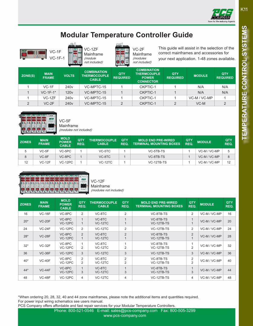
ZONES MAINFRAME
MOLDPOWER CABLE
QTYREQ.
THERMOCOUPLECABLE
QTYREQ.
MOLD END PRE-WIRED TERMINAL MOUNTING BOXES
QTYREQ. MODULE QTY
REQ.
5 VC-5F VC-5PC 1 VC-5TC 1 VC-5TB-TS 1 VC-M / VC-MP 5
8 VC-8F VC-8PC 1 VC-8TC 1 VC-8TB-TS 1 VC-M / VC-MP 8
12 VC-12F VC-12PC 1 VC-12TC 1 VC-12TB-TS 1 VC-M / VC-MP 12
ZONES MAINFRAME
MOLD POWERCABLE
QTYREQ.
THERMOCOUPLECABLE
QTYREQ.
MOLD END PRE-WIRED TERMINAL MOUNTING BOXES
QTYREQ. MODULE QTY
REQ.
16 VC-16F VC-8PC 2 VC-8TC 2 VC-8TB-TS 2 VC-M / VC-MP 16
20* VC-20F VC-8PC VC-12PC
11
VC-8TC VC-12TC
11
VC-8TB-TS VC-12TB-TS
11 VC-M / VC-MP 20
24 VC-24F VC-12PC 2 VC-12TC 2 VC-12TB-TS 2 VC-M / VC-MP 24
28* VC-28F VC-8PC VC-12PC
21
VC-8TC VC-12TC
21
VC-8TB-TS VC-12TB-TS
21 VC-M / VC-MP 28
32* VC-32F VC-8PC VC-12PC
12
VC-8TC VC-12TC
12
VC-8TB-TS VC-12TB-TS
12 VC-M / VC-MP 32
36 VC-36F VC-12PC 3 VC-12TC 3 VC-12TB-TS 3 VC-M / VC-MP 36
40* VC-40F VC-8PC VC-12PC
22
VC-8TC VC-12TC
22
VC-8TB-TS VC-12TB-TS
22 VC-M / VC-MP 40
44* VC-44F VC-8PC VC-12PC
13
VC-8TC VC-12TC
13
VC-8TB-TS VC-12TB-TS
13 VC-M / VC-MP 44
48 VC-48F VC-12PC 4 VC-12TC 4 VC-12TB-TS 4 VC-M / VC-MP 48
ZONE(S) MAIN FRAME VOLTS
COMBINATIONTHERMOCOUPLE
CABLE
QTYREQUIRED
COMBINATIONTHERMCOUPLE
POWERCONNECTOR
QTYREQUIRED MODULE QTY
REQUIRED
1 VC-1F 240v VC-MPTC-15 1 CKPTIC-1 1 N/A N/A1 VC-1F-1* 120v VC-MPTC-15 1 CKPTIC-1 1 N/A N/A1 VC-1ZF 240v VC-MPTC-15 1 CKPTIC-1 1 VC-M / VC-MP 12 VC-2F 240v VC-MPTC-15 2 CKPTIC-1 2 VC-M 2
*When ordering 20, 28, 32, 40 and 44 zone mainframes, please note the additional items and quantities required.For power input wiring schematics see users manual.PCS Company offers affordable and fast repair services for your Modular Temperature Controllers.
This guide will assist in the selection of thecorrect mainframes and accessories foryour next application. 1-48 zones available.
VC-1ZFMainframe(module not included)
VC-1F VC-2F Mainframe(modules not included)
VC-5F Mainframe(modules not included)
VC-12F Mainframe(modules not included)
VC-1F-1
Modular Temperature Controller Guide

Phone: 800-521-0546 E-mail: [email protected] Fax: 800-505-3299www.pcs-company.com
K12TE
MPE
RAT
UR
E C
ON
TRO
L SY
STEM
STE
MPE
RAT
UR
E C
ON
TRO
L SY
STEM
S
The diagram below provides amperage and stack heights of modular controllers.
100 Amp breaker available upon request
VC-1ZF10 Amp Breaker
VC-2F 20 Amp Breaker
VC-5F 50 Amp Breaker
VC-8F 50 Amp Breaker
VC-12F 50 Amp Breaker
VC-24F 70 Amp Breaker
VC-20F 70 Amp Breaker
VC-16F 70 Amp Breaker
VC-28F 70 Amp Breaker
VC-32F 70 Amp Breaker
VC-36F 70 Amp Breaker
VC-40F 70 Amp Breaker
VC-44F 70 Amp Breaker
VC-48F 70 Amp Breaker
27” H Stack
Frames
18” H Stack
Frames
36” H Stack
Frames
VC-1F & VC-1F-1(Horizontal)10 Amp Breaker
9” H
Frame
Modular Temperature Controller Mainframe System Configurations

Phone: 800-521-0546 E-mail: [email protected] Fax: 800-505-3299www.pcs-company.com
K13
TEM
PER
ATU
RE
CO
NTR
OL
SYST
EMS
TEM
PER
ATU
RE
CO
NTR
OL
SYST
EMS
Mainframe Alarm Modules
• Does not require a mainframe zone slot - fits in standard mainframe breaker panel position.• Powered from the mainframe power distribution buss. Isolation provided for power and alarm signals.• Visual and Audible fault alarms• Auxiliary dry-contact closure / open upon alarm that can be used to interface with press controls or other ancillary monitoring equipment.• Compatible with many industry standard mold temperature control modules with alarm communications capability.• Easy to retrofit into mainframes already in service. Step-by-step installation instructions are provided.• ** Mainframe Communications Buss Is Required **
The MFTA-205 Over / Under Temperature Alarm Accessory has been introduced to complete the PCS Company family of G-Series† style mainframe control systems. This control system was designed to provide affordable and compatible solutions for hot runner control requirements. The mainframes, when combined with the VC-M digital temperature control module, provide the user with a temperature control sys-tem that is user friendly, highly accurate and prepared to handle even the most dif-ficult control applications. The MFTA completes the package by providing an audible alarm, as well as auxiliary contact closures, in the event that an uncontrolled event occurs.
CATALOG NO. DESCRIPTIONMFTA-205 Over/Under Alarm Kit
CIK-5 5 Zone Communications BussCIK-8 8 Zone Communications Buss
CIK-12 12 Zone Communications BussCIK-16 16 Zone Communications BussCIK-24 24 Zone Communications Buss

Phone: 800-521-0546 E-mail: [email protected] Fax: 800-505-3299www.pcs-company.com
K14TE
MPE
RAT
UR
E C
ON
TRO
L SY
STEM
STE
MPE
RAT
UR
E C
ON
TRO
L SY
STEM
S
CATALOGNO.
NUMBER OFZONES (Max.)
FROM 15 ampMAINFRAME(S)
TOMOLD END LENGTH
VC-5PC10 5 5, 8, 12 zone VC-5MPC 10 ft.VC-8PC10 8 8, 12 zone VC-8MPC 10 ft.
VC-12PC10 12 12 zone VC-12MPC 10 ft.VC-5PC 5 5, 8, 12 zone VC-5MPC 15 ft.VC-8PC 8 8, 12 zone VC-8MPC 15 ft.
VC-12PC 12 12 zone VC-12MPC 15 ft.VC-5PC20 5 5, 8, 12 zone VC-5MPC 20 ft.VC-8PC20 8 8, 12 zone VC-8MPC 20 ft.
VC-12PC20 12 12 zone VC-12MPC 20 ft.
Mold Power cables
Thermocouple cables
Power & Thermocouple combinationcable 10 & 15 ft. lengths
Thermocouple cables are used to connect the mainframe to the thermo-couple connector on the mold. Available in lengths of 15 feet.
Mold power cables are used to connect the mainframe to the power input connector on the mold. Available in lengths of 10, 15 & 20 feet. The VC-12PC mold power cable also serves as a universal cable for connecting any 15 Amp mainframe to any 15 Amp mold power input connector. The maximum number of zones will be determined by the connector in the mold.
*Custom lengths and connectors available upon request.Special Power and Thermocouple Cables Available Upon Request.
CATALOGNO.
NUMBER OFZONES (Max.)
FROM 15 ampMAINFRAME(S)
TOMOLD END LENGTH
VC-5TC10 5 5, 8, 12 zone VC-5MTC 10 ft.VC-8TC10 8 8, 12 zone VC-8MTC 10 ft.
VC-12TC10 12 12 zone VC-12MTC 10 ft.VC-5TC 5 5, 8, 12 zone VC-5MTC 15 ft.VC-8TC 8 8, 12 zone VC-8MTC 15 ft.
VC-12TC 12 12 zone VC-12MTC 15 ft.VC-5TC20 5 5, 8, 12 zone VC-5MTC 20 ft.VC-8TC20 8 8, 12 zone VC-8MTC 20 ft.
VC-12TC20 12 12 zone VC-12MTC 20 ft.
CATALOG NO.
NUMBER OF ZONES (Max.)
FROM 10 amp MAINFRAME(S)
TO MOLD END
VC-MPTC-10 1 1, 2 zone CKPTIC-1
VC-MPTC-15 1 1, 2 zone CKPTIC-1
Mold Power & Thermocouple Cables
Phone: 800-521-0546 E-mail: [email protected] Fax: 800-505-3299www.pcs-company.com
K15
TEM
PER
ATU
RE
CO
NTR
OL
SYST
EMS
TEM
PER
ATU
RE
CO
NTR
OL
SYST
EMS
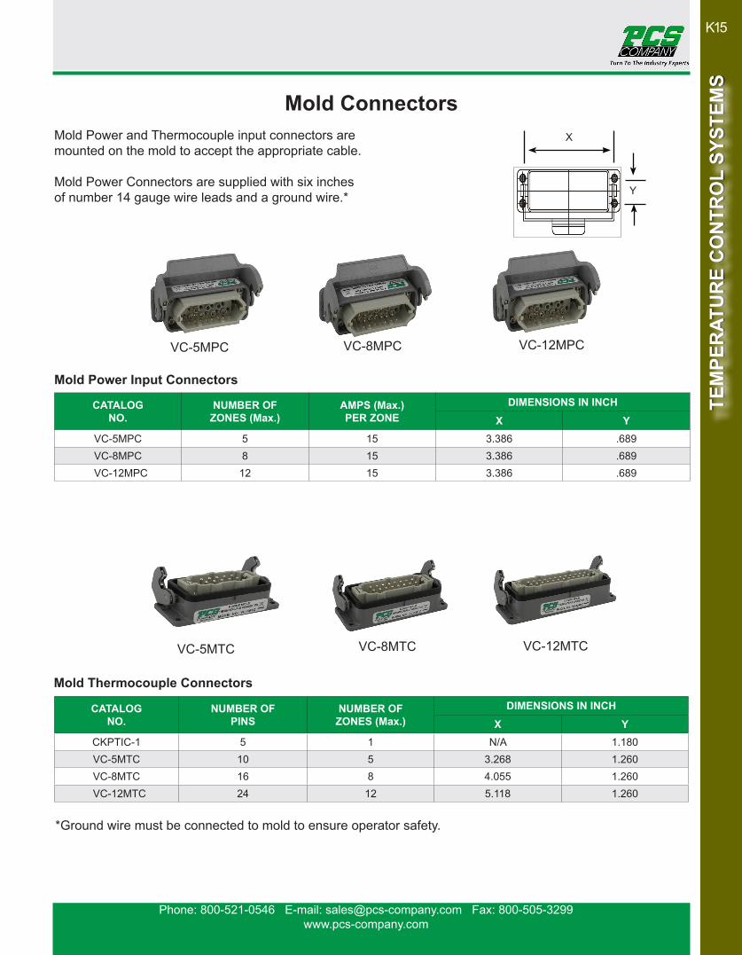
CATALOGNO.
NUMBER OFZONES (Max.)
AMPS (Max.)PER ZONE
DIMENSIONS IN INCH
X YVC-5MPC 5 15 3.386 .689VC-8MPC 8 15 3.386 .689
VC-12MPC 12 15 3.386 .689
CATALOGNO.
NUMBER OFPINS
NUMBER OFZONES (Max.)
DIMENSIONS IN INCH
X YCKPTIC-1 5 1 N/A 1.180VC-5MTC 10 5 3.268 1.260VC-8MTC 16 8 4.055 1.260
VC-12MTC 24 12 5.118 1.260
Mold Power Input Connectors
Mold Thermocouple Connectors
X
Y
VC-5MPC VC-8MPC VC-12MPC
VC-5MTC VC-8MTC VC-12MTC
Mold Power and Thermocouple input connectors are mounted on the mold to accept the appropriate cable.
Mold Power Connectors are supplied with six inches of number 14 gauge wire leads and a ground wire.*
*Ground wire must be connected to mold to ensure operator safety.
Mold Connectors

Phone: 800-521-0546 E-mail: [email protected] Fax: 800-505-3299www.pcs-company.com
K16TE
MPE
RAT
UR
E C
ON
TRO
L SY
STEM
STE
MPE
RAT
UR
E C
ON
TRO
L SY
STEM
S
CATALOG NO.
MAINFRAMEZONES
QUANTITYREQUIRED
ADDITIONALCATALOG NO.
ADDITIONALQUANTITY REQUIRED
VC-2TB-TS 2 1VC-5TB-TS 5 1VC-8TB-TS 8 1
VC-12TB-TS 12 1
VC-8TB-TS 16 2
VC-8TB-TS 20* 1 VC-12TB-TS 1 VC-12TB-TS 24 2VC-8TB-TS 28* 2 VC-12TB-TS 1VC-8TB-TS 32* 1 VC-12TB-TS 2
VC-12TB-TS 36 3VC-8TB-TS 40* 2 VC-12TB-TS 2VC-8TB-TS 44* 1 VC-12TB-TS 3
VC-12TB-TS 48 4
*When ordering 20, 28, 32, 40 and 44 zones, please note the additional items and quantities required.
When ordering combination mounting boxes, choose the item number and required quantity for the selected mainframe zones.
VC-5TB-TS VC-8TB-TS VC-12TB-TSVC-2TB-TS
Pre-Wired Terminal Mounting Boxes

Phone: 800-521-0546 E-mail: [email protected] Fax: 800-505-3299www.pcs-company.com
K17
TEM
PER
ATU
RE
CO
NTR
OL
SYST
EMS
TEM
PER
ATU
RE
CO
NTR
OL
SYST
EMS
CATALOGNO.
DIMENSIONS IN INCHINCLUDES
Y X H M1 M2
VC-2TB-TS 2.750 4.880 4.250 1.500 4.250 (2) CKPTIC-1
VC-5TB-TS 2.750 8.660 4.250 1.500 8.031 VC-5MPC, VC-5MTC
VC-8TB-TS 2.750 9.470 4.250 1.500 8.843 VC-8MPC, VC-8MTC
VC-12TB-TS 2.750 10.530 4.250 1.500 9.906 VC-12MPC, VC-12MTC
Comes with all necessary connectors installed and pre-wired to the terminal strip.
VC-2TB-TS
VC-5TB-TS
VC-8TB-TS
VC-12TB-TS
• Choose Prewired Terminal Mounting Boxes to save time and money during installation. • Comes with all necessary connectors for easy set up.• Service friendly maintenance.
M= Mounting screw spacing. Clearance for 1/4 SHCS.
Pre-Wired Terminal Mounting Boxes

Phone: 800-521-0546 E-mail: [email protected] Fax: 800-505-3299www.pcs-company.com
K18TE
MPE
RAT
UR
E C
ON
TRO
L SY
STEM
STE
MPE
RAT
UR
E C
ON
TRO
L SY
STEM
S
CATALOGNO.
DIMENSIONS IN INCHACCEPTS
Y X H M1 M2
VC-2TB 2.750 4.880 4.250 1.500 4.250 (2) CKPTIC-1
VC-5TB 2.750 8.660 4.250 1.500 8.031 VC-5MPC, VC-5MTC
VC-8TB 2.750 9.470 4.250 1.500 8.843 VC-8MPC, VC-8MTC
VC-12TB 2.750 10.530 4.250 1.500 9.906 VC-12MPC, VC-12MTC
VC-5TB
VC-8TB
VC-12TB
VC-2TB
Choose the Combination Terminal Mounting Box for its economical and rugged design.
M= Mounting screw spacing. Clearance for 1/4 SHCS.
Combination Terminal Mounting Boxes

Phone: 800-521-0546 E-mail: [email protected] Fax: 800-505-3299www.pcs-company.com
K19
TEM
PER
ATU
RE
CO
NTR
OL
SYST
EMS
TEM
PER
ATU
RE
CO
NTR
OL
SYST
EMS
PCS / DME Style
PCS / DME Style
PCS / DME Style
OEM Prewired Terminal Mounting Boxes

Phone: 800-521-0546 E-mail: [email protected] Fax: 800-505-3299www.pcs-company.com
K20TE
MPE
RAT
UR
E C
ON
TRO
L SY
STEM
STE
MPE
RAT
UR
E C
ON
TRO
L SY
STEM
S
Generic Style
DME High Power Style
Mold Masters Style
HBE24 Double Latch Style
OEM Prewired Terminal Mounting Boxes
Phone: 800-521-0546 E-mail: [email protected] Fax: 800-505-3299www.pcs-company.com
K21
TEM
PER
ATU
RE
CO
NTR
OL
SYST
EMS
TEM
PER
ATU
RE
CO
NTR
OL
SYST
EMS
CATALOGNO.
OEM STYLE
DIMENSIONS IN INCHACCEPTS
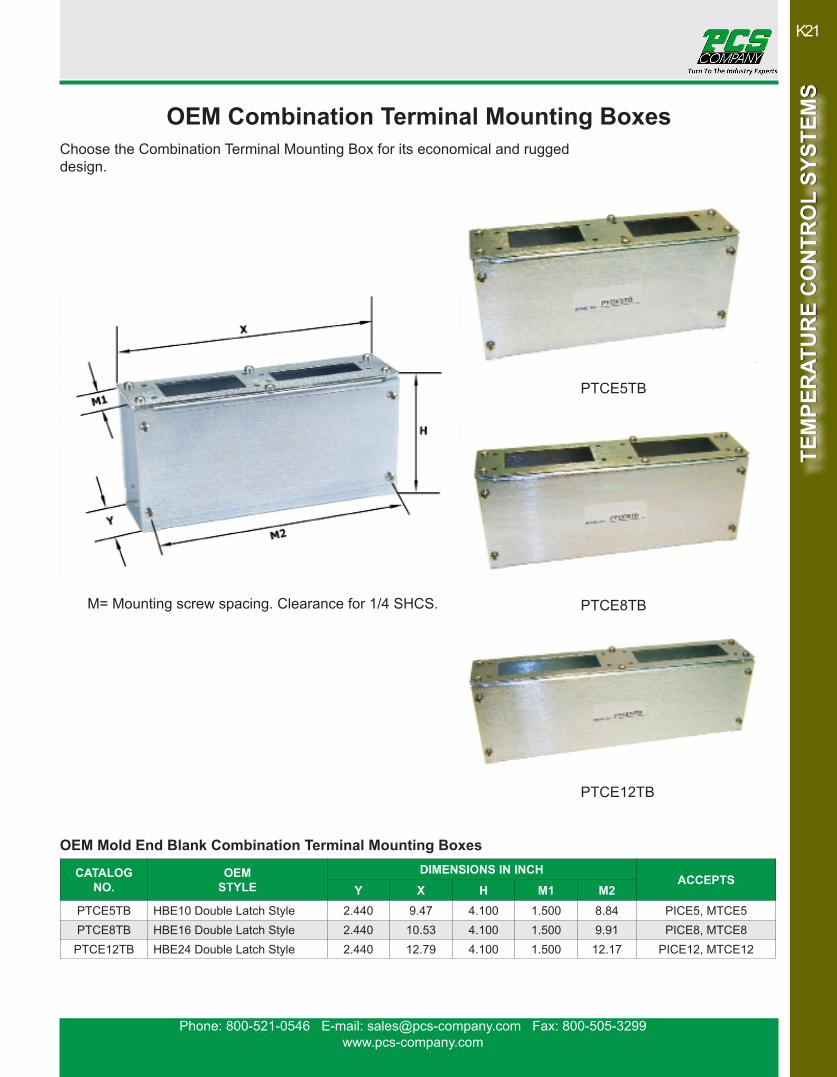
Y X H M1 M2PTCE5TB HBE10 Double Latch Style 2.440 9.47 4.100 1.500 8.84 PICE5, MTCE5PTCE8TB HBE16 Double Latch Style 2.440 10.53 4.100 1.500 9.91 PICE8, MTCE8
PTCE12TB HBE24 Double Latch Style 2.440 12.79 4.100 1.500 12.17 PICE12, MTCE12
OEM Mold End Blank Combination Terminal Mounting Boxes
PTCE8TB
PTCE12TB
PTCE5TB
Choose the Combination Terminal Mounting Box for its economical and rugged design.
M= Mounting screw spacing. Clearance for 1/4 SHCS.
OEM Combination Terminal Mounting Boxes

Phone: 800-521-0546 E-mail: [email protected] Fax: 800-505-3299www.pcs-company.com
K22TE
MPE
RAT
UR
E C
ON
TRO
L SY
STEM
STE
MPE
RAT
UR
E C
ON
TRO
L SY
STEM
S
CATALOGNO.
OEM STYLE
# OF ZONES (Max.)
FROM 15 ampMAINFRAME(S)
TO DOUBLE LATCH
MOLD ENDLENGTH
MPCE5-10 HBE10 Double Latch to PCS/DME Style 5 5, 8, 12 Zone PICE5 10 ft.MPCE8-10 HBE16 Double Latch to PCS/DME Style 8 5, 8, 12 Zone PICE8 10 ft.
MPCE12-10 HBE24 Double Latch to PCS/DME Style 12 5, 8, 12 Zone PICE12 10 ft.MPCE5-20 HBE10 Double Latch to PCS/DME Style 5 5, 8, 12 Zone PICE5 20 ft.MPCE8-20 HBE16 Double Latch to PCS/DME Style 8 5, 8, 12 Zone PICE8 20 ft.
MPCE12-20 HBE24 Double Latch to PCS/DME Style 12 5, 8, 12 Zone PICE12 20 ft.
OEM Mold Power Conversion Cables
OEM Thermocouple Conversion Cables
OEM Power & Thermocouple Cable
*Custom lengths and connectors available upon request.
CATALOGNO.
OEM STYLE
# OF ZONES (Max.)
FROM 15 ampMAINFRAME(S)
TO DOUBLE LATCH
MOLD ENDLENGTH
TCE5-10 HBE10 Double Latch to PCS/DME Style 5 5, 8, 12 Zone MTCE5 10 ftTCE8-10 HBE16 Double Latch to PCS/DME Style 8 5, 8, 12 Zone MTCE8 10 ft
TCE12-10 HBE24 Double Latch to PCS/DME Style 12 5, 8, 12 Zone MTCE12 10 ftTCE5-20 HBE10 Double Latch to PCS/DME Style 5 5, 8, 12 Zone MTCE5 20 ft.TCE8-20 HBE16 Double Latch to PCS/DME Style 8 5, 8, 12 Zone MTCE8 20 ft.
TCE12-20 HBE24 Double Latch to PCS/DME Style 12 5, 8, 12 Zone MTCE12 20 ft.
CATALOGNO.
OEM STYLE
# OF ZONES (Max.)
FROM 15 ampMAINFRAME(S)
TO DOUBLE LATCHMOLD END LENGTH
PITC12-10 Mold Masters Style 12 12 Zone PITC12 10 ft.
PITC12-20 Mold Masters Style 12 12 Zone PITC12 20 ft.
CATALOGNO.
OEM STYLE
# OF ZONES (Max.)
FROM 15 ampMAINFRAME(S)
TO DOUBLE LATCH
MOLD ENDLENGTH
PITC12- 10YFE
Mold Masters Mold End to
PCS/DME Style
12 power & 12 thermocouple PCS Standard 5, 8, 12 Zone PITC12 10 ft.
PITC12- 20YFE
Mold Masters Mold End to
PCS/DME Style
12 power & 12 thermocouple PCS Standard 5, 8, 12 Zone PITC12 20 ft.
PITC12- 10YME
Mold Masters Mold End to
PCS/DME Style
12 power & 12 thermocouple
From 15 Amp mainframe(s) using HBE / HAN 48 power &
thermocouple connector
VC-12MPC & VC-12MTC 10 ft.
PITC12- 20YME
Mold Masters Mold End to
PCS/DME Style
12 power & 12 thermocouple
From 15 Amp mainframe(s) using HBE / HAN 48 power &
thermocouple connector
VC-12MPC & VC-12MTC 20 ft.
OEM Split Combination Power & Thermocouple Cables
OEM Mold Power & Thermocouple Conversion Cables

Phone: 800-521-0546 E-mail: [email protected] Fax: 800-505-3299www.pcs-company.com
K23
TEM
PER
ATU
RE
CO
NTR
OL
SYST
EMS
TEM
PER
ATU
RE
CO
NTR
OL
SYST
EMS
CATALOGNO.
OEM STYLE
NUMBER OFZONES (Max.)
AMPS (Max.)PER ZONE
DIMENSIONS IN INCH
X YPICE5 HBE10 Double Latch Style 5 15 3.86 1.260PICE8 HBE16 Double Latch Style 8 15 3.86 1.260
PICE12 HBE24 Double Latch Style 12 15 3.86 1.260
CATALOGNO.
OEM STYLE
NUMBER OFZONES (Max.)
NUMBEROF PINS
DIMENSIONS IN INCH
X Y
MTCE5 HBE10 Double Latch Style 5 10 3.268 1.260MTCE8 HBE16 Double Latch Style 8 16 4.055 1.260
MTCE12 HBE24 Double Latch Style 12 24 5.118 1.260
OEM Mold Power Input Connectors
OEM Mold Thermocouple Connectors
X
Y
Mold Power and Thermocouple input connectors are mounted on the mold to accept the appropriate cable. Mold Power Connectors are supplied with six inches of number 14 gauge wire leads and a ground wire.*
*Ground wire must be connected to mold to ensure operator safety.
OEM Mold Power & Thermocouple Connector
PICE5 PICE8 PICE12
CATALOGNO.
OEM STYLE
NUMBER OFZONES (Max.)
AMPS (Max.)
PER ZONE
NUMBEROF PINS
DIMENSIONS IN INCH
X Y
PITC12 Mold Masters Style 12 power & 12 thermocouple 15 2 x 24 5.827 2.756
MTCE5 MTCE8 MTCE12
OEM Mold Connectors
CATALOGNO.
OEM STYLE
NUMBER OFZONES (Max.)
AMPS (Max.)PER ZONE
DIMENSIONS IN INCHX Y
PICH5 Mold Masters Style 5 30 4.88 3.12
OEM High Performance Mold Power Input Connector

Phone: 800-521-0546 E-mail: [email protected] Fax: 800-505-3299www.pcs-company.com
K24TE
MPE
RAT
UR
E C
ON
TRO
L SY
STEM
STE
MPE
RAT
UR
E C
ON
TRO
L SY
STEM
S
CATALOG NO. ITEM DESCRIPTION
HWCC-1 T/C crimp connectors 18-22AWG (30 pack)
CATALOG NO. ITEM DESCRIPTION
HWCC-3 PWR crimp connectors14-16 AWG (30 pack)
CATALOG NO. ITEM DESCRIPTION
ABC-10 10 amp module fusereplacements (5 pack)
CATALOG NO. ITEM DESCRIPTION
ABC-15 15 amp module fusereplacements (5 pack)
CATALOG NO. ITEM DESCRIPTION
CKPTF-1L 1 zone cable connector female with latch
CATALOG NO. ITEM DESCRIPTION
AC2024F 240v power input connector
CATALOG NO. ITEM DESCRIPTION
CKF-312-G Edge card connector
CATALOG NO. ITEM DESCRIPTION
CKPTM-1L 1 zone cable connector male with latch
CATALOG NO. ITEM DESCRIPTION
AC1512F 120v power cable connector
CATALOG NO. ITEM DESCRIPTION
R144-002 Mainframe Rails
Replacement Parts

Phone: 800-521-0546 E-mail: [email protected] Fax: 800-505-3299www.pcs-company.com
K25
TEM
PER
ATU
RE
CO
NTR
OL
SYST
EMS
TEM
PER
ATU
RE
CO
NTR
OL
SYST
EMS
Replacement Parts
CATALOG NO. ITEM DESCRIPTION
CKTF-112-AG T/C cables frame end kit
CATALOG NO. ITEM DESCRIPTION
CKTF-112-G 12 zone T/C cable mold end kit
CATALOG NO. ITEM DESCRIPTION
CKPM-112-BG Power cable frame end kit
CATALOG NO. ITEM DESCRIPTION
CKPF-112-BG Power cable mold end kit
CATALOG NO. ITEM DESCRIPTION
CKTF-15-G 5 zone T/C cable mold end kit
CATALOG NO. ITEM DESCRIPTION
CKTF-18-G 8 zone T/C cable mold end kit
CATALOG NO. ITEM DESCRIPTION
CKPTF-1 1 zone cable connector female without latch
CATALOG NO. ITEM DESCRIPTION
CKPTM-1 1 zone cable connector malewithout latch
CATALOG NO. ITEM DESCRIPTION
CKPTIC-1 1 zone 10 Amp mold power & T/C connector
CATALOG NO. ITEM DESCRIPTION
CKPTOC1 1 zone 10 amp mainframe power & T/C connector

Phone: 800-521-0546 E-mail: [email protected] Fax: 800-505-3299www.pcs-company.com
K26TE
MPE
RAT
UR
E C
ON
TRO
L SY
STEM
STE
MPE
RAT
UR
E C
ON
TRO
L SY
STEM
S
CATALOG NO. ITEM DESCRIPTION
VC-10BP Mainframe blank panel
CATALOG NO. ITEM DESCRIPTION
VC-FS Floor Stand(Mainframe not included)
Step Down Transformer KitPCS Transformer Kits are pre-wired and include an enclosed transformer (3-phase, 480 VAC input, 240 VAC output) with adjustable transformer primary voltage taps, one 10-foot cable for AC power-in (no connector), one 6-foot cable for mainframe (AC input), one fused safety switch, two extra fuses, floor stand, and all mounting brackets and required hardware.
Product not shown*Floor Stand Included
CATALOG NO. ITEM DESCRIPTION
TK61AG* TK91AG*TK151AG*TK301AG*
6 KVA Transformer Kit9 KVA Transformer Kit15 KVA Transformer Kit30 KVA Transformer Kit
CATALOG NO. ITEM DESCRIPTION
PIN0114 Male pin for power connector (30 pack)
CATALOG NO. ITEM DESCRIPTION
R144-017 T/C ferrules (50 pack)
CATALOG NO. ITEM DESCRIPTION
R172-002 White edge card contacts (20 pack)
Assembly and mainframe mounting hardware included. Stand is made from heavy gauge steel and includes locking casters (400lb. rating).
CATALOG NO. ITEM DESCRIPTION
PCT1000 Crimp tool
CATALOG NO. ITEM DESCRIPTION
PET0001 Pin extraction tool
Replacement Parts & Accessories
Phone: 800-521-0546 E-mail: [email protected] Fax: 800-505-3299www.pcs-company.com
K27
TEM
PER
ATU
RE
CO
NTR
OL
SYST
EMS
TEM
PER
ATU
RE
CO
NTR
OL
SYST
EMS
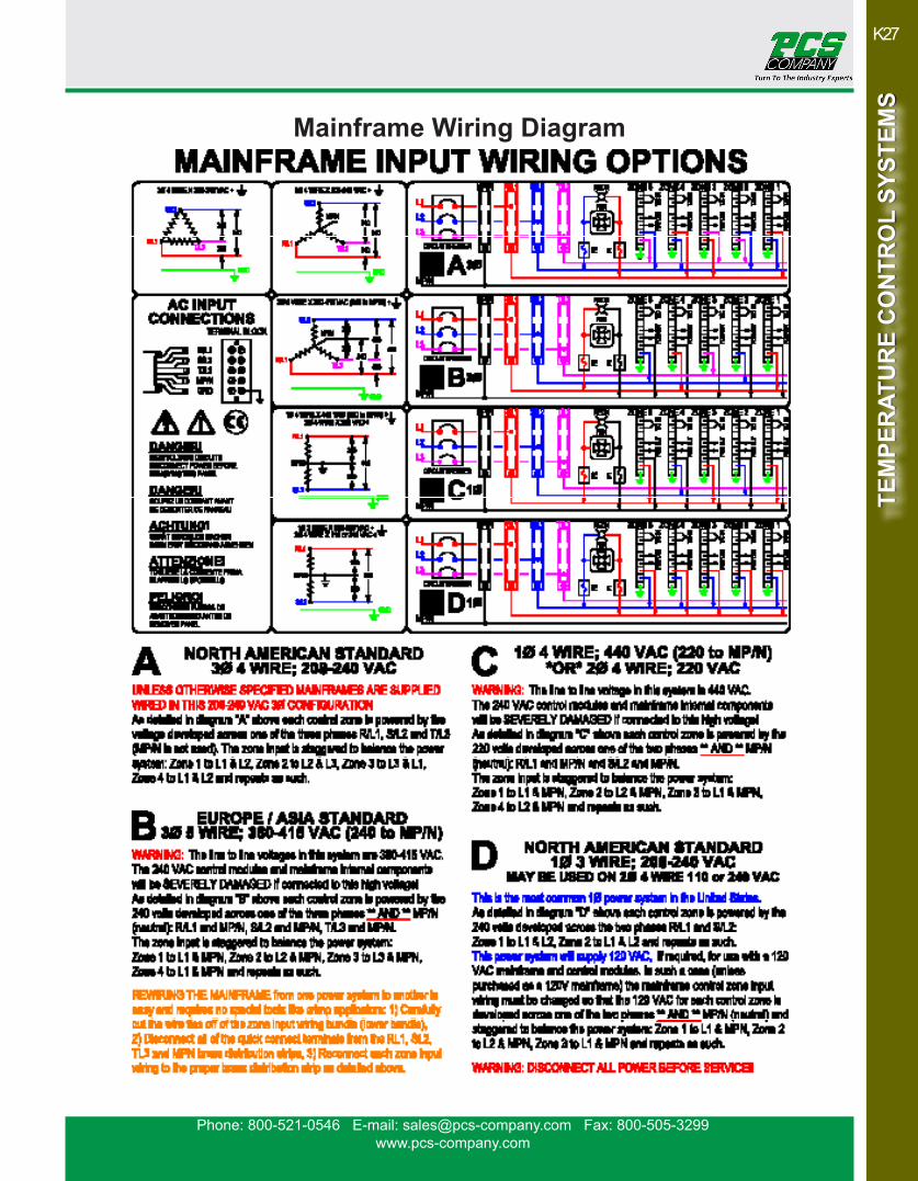
Mainframe Wiring Diagram
Phone: 800-521-0546 E-mail: [email protected] Fax: 800-505-3299www.pcs-company.com
K28TE
MPE
RAT
UR
E C
ON
TRO
L SY
STEM
STE
MPE
RAT
UR
E C
ON
TRO
L SY
STEM
S
A
B
C
D
E I
GH
FEMALE
F
MALE
MOLD POWER CABLE
THERMOCOUPLE CABLE
REFERENCELETTER DESCRIPTION CATALOG
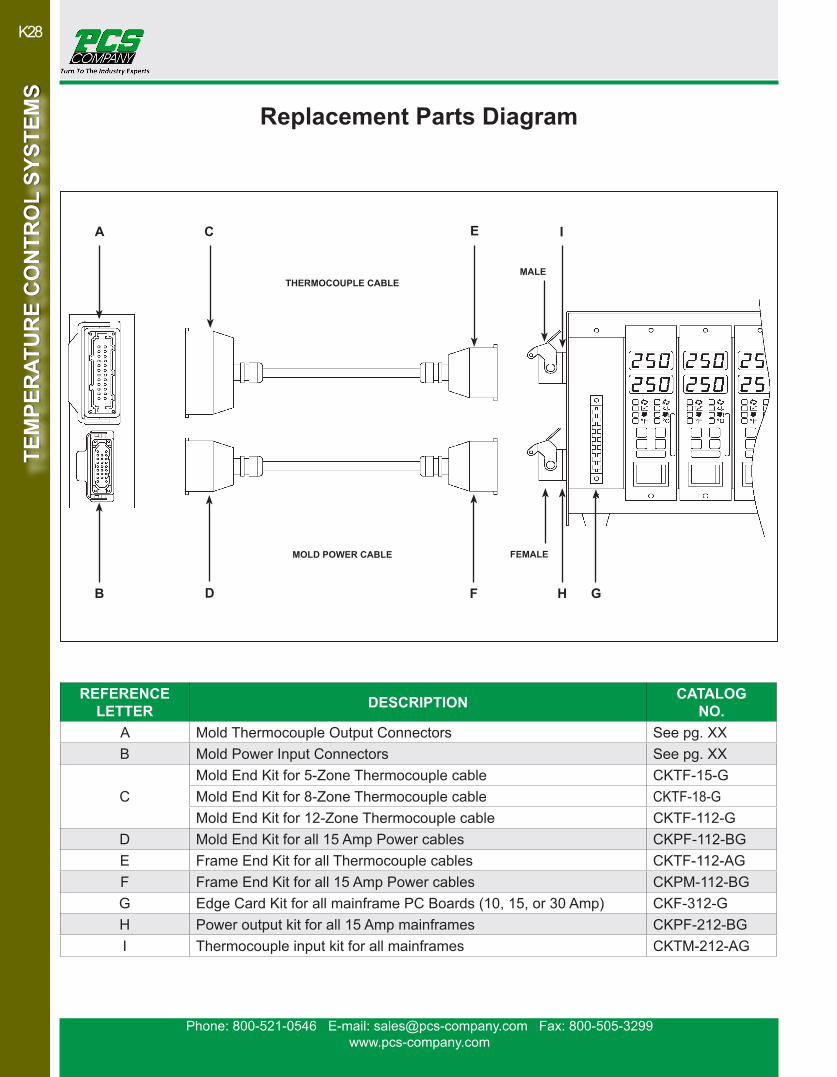
NO.A Mold Thermocouple Output Connectors See pg. XXB Mold Power Input Connectors See pg. XX
CMold End Kit for 5-Zone Thermocouple cable CKTF-15-GMold End Kit for 8-Zone Thermocouple cable CKTF-18-GMold End Kit for 12-Zone Thermocouple cable CKTF-112-G
D Mold End Kit for all 15 Amp Power cables CKPF-112-BGE Frame End Kit for all Thermocouple cables CKTF-112-AGF Frame End Kit for all 15 Amp Power cables CKPM-112-BGG Edge Card Kit for all mainframe PC Boards (10, 15, or 30 Amp) CKF-312-GH Power output kit for all 15 Amp mainframes CKPF-212-BGI Thermocouple input kit for all mainframes CKTM-212-AG
Replacement Parts Diagram
Phone: 800-521-0546 E-mail: [email protected] Fax: 800-505-3299www.pcs-company.com
K29
TEM
PER
ATU
RE
CO
NTR
OL
SYST
EMS
TEM
PER
ATU
RE
CO
NTR
OL
SYST
EMS
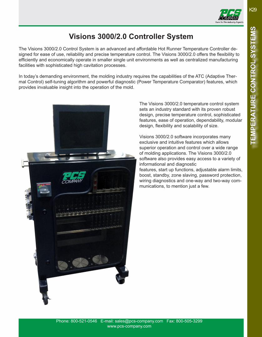
The Visions 3000/2.0 Control System is an advanced and affordable Hot Runner Temperature Controller de-signed for ease of use, reliability and precise temperature control. The Visions 3000/2.0 offers the flexibility to efficiently and economically operate in smaller single unit environments as well as centralized manufacturing facilities with sophisticated high cavitation processes.
In today’s demanding environment, the molding industry requires the capabilities of the ATC (Adaptive Ther-mal Control) self-tuning algorithm and powerful diagnostic (Power Temperature Comparator) features, which provides invaluable insight into the operation of the mold.
The Visions 3000/2.0 temperature control system sets an industry standard with its proven robust design, precise temperature control, sophisticated features, ease of operation, dependability, modular design, flexibility and scalability of size.
Visions 3000/2.0 software incorporates many exclusive and intuitive features which allows superior operation and control over a wide range of molding applications. The Visions 3000/2.0 software also provides easy access to a variety of informational and diagnostic features, start up functions, adjustable alarm limits, boost, standby, zone slaving, password protection, wiring diagnostics and one-way and two-way com-munications, to mention just a few.
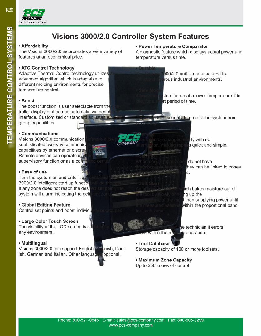
Visions 3000/2.0 Controller System
Phone: 800-521-0546 E-mail: [email protected] Fax: 800-505-3299www.pcs-company.com
K30TE
MPE
RAT
UR
E C
ON
TRO
L SY
STEM
STE
MPE
RAT
UR
E C
ON
TRO
L SY
STEM
S
• AffordabilityThe Visions 3000/2.0 incorporates a wide variety of features at an economical price.
• ATC Control TechnologyAdaptive Thermal Control technology utilizes an advanced algorithm which is adaptable to different molding environments for precise temperature control.
• BoostThe boost function is user selectable from the con-troller display or it can be automatic via peripheral interface. Customized or standard adjustable power group capabilities.
• CommunicationsVisions 3000/2.0 communication software allows sophisticated two-way communication capabilities by ethernet or discrete protocol. Remote devices can operate in either a supervisory function or as a command center.
• Ease of useTurn the system on and enter set points and Visions 3000/2.0 intelligent start up function will do the rest. If any zone does not reach the desired set point, the system will alarm indicating the deficient zone.
• Global Editing FeatureControl set points and boost individually or grouped.
• Large Color Touch ScreenThe visibility of the LCD screen is suitable forany environment.
• MultilingualVisions 3000/2.0 can support English, Spanish, Dan-ish, German and Italian. Other languages optional.
• Power Temperature ComparatorA diagnostic feature which displays actual power and temperature versus time. • DurableThe Visions 3000/2.0 unit is manufactured to withstand rigorous industrial environments. • Safe ModeAllows the system to run at a lower temperature if in idle, for a short period of time.
• SecurityThree levels of security to protect the system from tampering.
• ServiceCards can be changed easily with no interruption, making repairs quick and simple.
• SlavingWhen one or more zones do not have thermocouple feedback, they can be linked to zones with similar characteristics.
• Soft StartAn automatic feature which bakes moisture out of the tool by slowly bringing up the temperature of the mold then supplying power until the measured value is within the proportional band for each zone.
• System AlarmThe system will alert the technician if errors occur within the molding operation.
• Tool DatabaseStorage capacity of 100 or more toolsets.
• Maximum Zone CapacityUp to 256 zones of control
Visions 3000/2.0 Controller System Features

Phone: 800-521-0546 E-mail: [email protected] Fax: 800-505-3299www.pcs-company.com
K31
TEM
PER
ATU
RE
CO
NTR
OL
SYST
EMS
TEM
PER
ATU
RE
CO
NTR
OL
SYST
EMS
• Self DiagnosticsThe Visions 3000/2.0 Tool Diagnostics Suite performs a full set of functional tests to determine the condition of the mold, controller and machine operation.
• Tool Diagnostics & ValidationTroubleshoots new or existing tools, checking for faults such as: – Swapped heater or thermocouple wires. If one is found, the controller indicates the affected zone.– Heater power monitoring (heater amperage and/or wattage) to detect current leakage– Heater resistance monitoring to predict
heater failure. – Thermocouple open, short, reversed, etc. – Measures resistance of each heater for
failure analysis.
• Machine InterfaceVisions 3000/2.0 can take a cyclical or constant input from the machine and tool while in production and trig-ger a shut down if operations cease after a selectable period of time.
• Visual DiagnosticsLED’s are visible on the front control panel monitoring CPU communications, fuse conditionand output activity of each zone.
• Surface GraphsSurface Graphs provide immediate insightinto the operation of all tool zones.
• Trend graphsProvides a scalable display of the historic valuesfor a particular zone.
Trend Chart
Trend Graph
Temperature Zone Display
Visions 3000/2.0 Controller System Features

Phone: 800-521-0546 E-mail: [email protected] Fax: 800-505-3299www.pcs-company.com
K32TE
MPE
RAT
UR
E C
ON
TRO
L SY
STEM
STE
MPE
RAT
UR
E C
ON
TRO
L SY
STEM
S
• Individual Heater Auto P.I.D Tuning:The Visions 3000/2.0 has enhanced the ability to fine tune the most troublesome of molds. Un-der normal operations, tuning is carried out during the warm up process, individually tuning each heater to control within 0.5° F of set point. The Auto Tune is carried out automatically each time the controller is turned on. Incorrect P.I.D. tuning is the main reason for inconsistent temperature control. For troublesome tools, auto tuning can be turned off allowing the operator to select from a range of 5 different settings which can fine tune the P.I.D. operating to match the tool.
• Individual Heater Alarm Tolerance Settings:Heaters can be allocated individual settings, to prevent global alarm settings being triggered by minority, problematic thermocouples. Each heater/thermocouple combination has it’s own trig-ger point and values assigned to operate independently.
• Individual Heater Power Consumption Monitoring:All Cavity heaters power consumption is constantly and individually monitored. Any increase in power demand is the first sign of a developing problem and early detection is vital in preventing avoidable scrap and tool down time in the machine.
• Programmable Manifold Pre-heat Start Up Groups:The user has the ability to define the start up sequence of the manifold heaters. This is useful for tools with a large number of heaters that ex-ceed the maximum current available if ramped together and provides the means to program the specific start up recommendations of the hot runner manufacturer, automatically balancing the hot runner during the critical warm up phase.
• 12 Months of Fully Downloadable Production History, Alarm Logs & Graphs:
All production data is automati-cally stored for a period of 12 months. Data includes, individu-al heater power usage and temperature during the produc-tion cycle, on a second by second basis. All initial set-up settings, user and set point changes made during production, Alarm activations and errors. Water flow (gallons/liters per minute) and water temperature (F° & C°). Tool diagnostic reports and set up files. All data is date and time
stamped and viewablefrom the Visions 3000/2.0 controller screen or downloadable to a PC or Laptop. Set up data is transferable between Visions 3000/2.0 controllers. Data cannot be deleted by the user and is password protected.
• USB, Ethernet & Wi-Fi for download, upload & real time off site monitoring:All data can be downloaded via USB to PC or Laptop for back up and viewing. The data can be viewed as a text file, spread sheet or in graph format, allowing for easy distribution of information, internally or to other group. Real time off site monitoring and ITC monitoring can be implemented via the Ethernet/Wi-Fi facility. This feature is particularly valuable for directly supporting International customers.
Visions 3000/2.0 Controller System Enhanced Features

Phone: 800-521-0546 E-mail: [email protected] Fax: 800-505-3299www.pcs-company.com
K33
TEM
PER
ATU
RE
CO
NTR
OL
SYST
EMS
TEM
PER
ATU
RE
CO
NTR
OL
SYST
EMS
• Real Time Water Flow Monitoring & Alarms (optional):Real Time water flow and temperature monitoring with warring alarms can now be automated via the Visions
3000/2.0 controller. Flow sensors are precisely installed in the PCS Smart Manifold with an interface module added to the Visions 3000/2.0 control. Any critical drop in the water flow rate will trigger a safety response from the Visions 3000/2.0 con-troller. If so setup, power can be cut to the tool heaters, a ma-chine stop trigger activated and machine alarm activated. No water, no power! The water data will also show trend changes and gradual flow reduction which is particularly useful for maintenance to monitor the condi-tion of the water filters. Multi channel water mapping of the tool willprovide significant information and production
benefits. All water data and alarm activations are recorded in the downloadable data and graphs history database.
• Minimum Cavity Set Point Temperature:It’s bad practice to turn off unused zones in any mold, this creates cold spots which can effect the balance and flow of material within the system. It’s much better to enter a low temperature that keeps the tool balanced, in a manner which won’t produce parts in any zones. The minimum set point option allows the supervisor to enter the minimum acceptable temperature, normally around 240° F (depending on the type of material). This will prevent the operator from turning the unused zones off, in its place they will have to enter a temperature instead of turning them off.
• Saved & Downloadable Diagnostic Reports:The tool diagnostic function is a very important facility. Not only for diagnosing tool problems, but as a means of tracking the performance and reliability of the heaters & thermocouples over time. Downloadable diagnostic reports allow the tool room to run comparison checks against previous service and repairs data to maintain a contemporaneous record of the tools history. The diagnostic reports provide useful evidence and can be submitted to the tool maker or hot runner manufacturer during quality disputes and tool trials prior to delivery. • Improved Diagnostic Graphs for Power, Temperature & Water Interrogation:The diagnostic trend and surface graphs have been improved to provide greater detail while presented in a simpler form. Many of the functions have been automated making them quick and easy to use and under-stand. The infor-mation provided is much clearer and more detailed, while being less cluttered. Water flow functions have been added to the suite of graphs, providing detailed analysis of both flow rate and temperature. A time line function has been introduced to the graphs to enable the production history to be searched for by specific times and dates during the previous 12 months.
• Industrial Grade Color Touch Screen Interface:The introduction of the Linux operating system has pre-sented the opportunity to maximize the potential of the touch screen interface, and fully utilizing all the benefits and advantages of touch screen technology. Like previous Visions 3000/2.0 systems we utilize 4mm safety glass as screen protection so the unit integrity is not compromised by the environment.
Visions 3000/2.0 Controller System Enhanced Features
Phone: 800-521-0546 E-mail: [email protected] Fax: 800-505-3299www.pcs-company.com
K34TE
MPE
RAT
UR
E C
ON
TRO
L SY
STEM
STE
MPE
RAT
UR
E C
ON
TRO
L SY
STEM
S
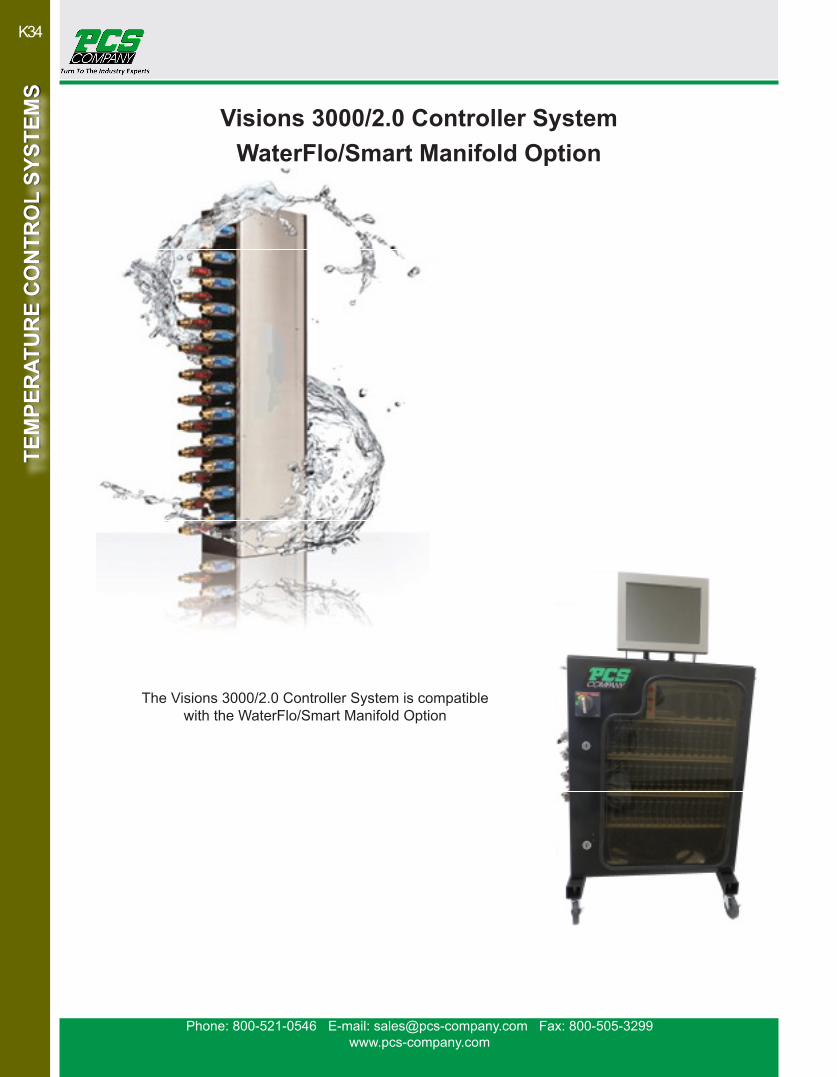
The Visions 3000/2.0 Controller System is compatible with the WaterFlo/Smart Manifold Option
Visions 3000/2.0 Controller System WaterFlo/Smart Manifold Option

Phone: 800-521-0546 E-mail: [email protected] Fax: 800-505-3299www.pcs-company.com
K35
TEM
PER
ATU
RE
CO
NTR
OL
SYST
EMS
TEM
PER
ATU
RE
CO
NTR
OL
SYST
EMS
Visions 3000/2.0 Controller System WaterFlo/Smart Manifold Option

Phone: 800-521-0546 E-mail: [email protected] Fax: 800-505-3299www.pcs-company.com
K36TE
MPE
RAT
UR
E C
ON
TRO
L SY
STEM
STE
MPE
RAT
UR
E C
ON
TRO
L SY
STEM
S
Visions 3000/2.0 Controller System WaterFlo/Smart Manifold Option
Phone: 800-521-0546 E-mail: [email protected] Fax: 800-505-3299www.pcs-company.com
K37
TEM
PER
ATU
RE
CO
NTR
OL
SYST
EMS
TEM
PER
ATU
RE
CO
NTR
OL
SYST
EMS
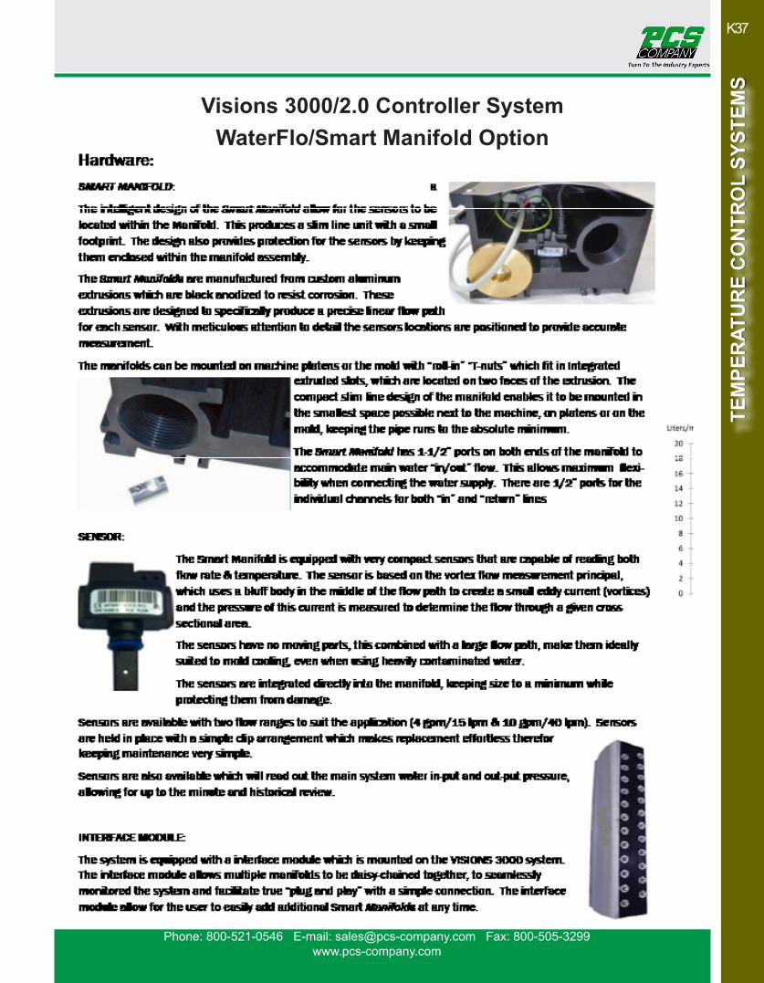
Visions 3000/2.0 Controller System WaterFlo/Smart Manifold Option

Phone: 800-521-0546 E-mail: [email protected] Fax: 800-505-3299www.pcs-company.com
K38TE
MPE
RAT
UR
E C
ON
TRO
L SY
STEM
STE
MPE
RAT
UR
E C
ON
TRO
L SY
STEM
S
Visions 3000/2.0 Controller System WaterFlo/Smart Manifold Option