telereader cwr-6850 manual - dl0bn.de cwr-6850 manual.pdf · this manual describes the installation...
TRANSCRIPT

CWR-6850TELEREADER
INSTRUCTION
MANUAL
QUALITY COMMUNICATIONS EQUIPMENT
April, 1982 PrintingReprint DC7XJ, Feb. 2017

CONTENTS
INTRODUCTION ............................................................................... 4
CHAPTER 1 UNPACKING AND INSPECTION ..................................... 5
CHAPTER 2 SIMPLE HOOK-UP AND OPERATION2.1 Connections to the CWR-6850 ............................. 72.2 Presetting CWR-6850 controls ............................ 82.3 Presetting the transceiver controls ...................... 92.4 RTTY operation ................................................. 92.5 Morse operation ................................................ 10
CHAPTER 3 RECEIVING WITH THE CWR-68503.1 Connecting the CWR-6850 to your Receiver ......... 123.2 Receiving RTTY signals ...................................... 133.3 Low tones or high tones? ................................... 153.4 Receiving Morse code ........................................ 17
CHAPTER 4 TRANSMITTING WITH THE CWR-68504.1 The keyboard ................................................... 194.2 Transmitting features ......................................... 204.3 Use of the HERE-IS message .............................. 234.4 Special considerations when transmitting Morse ... 264.5 Special considerations when transmitting Baudot . 284.6 Special considerations when transmitting ASCII ... 304.7 HDX / FDX operation ......................................... 334.8 The KOS feature ................................................ 34
CHAPTER 5 CONNECTIONS TO THE CWR-6850 ................................ 355.1 Normal Amateur Station connections .................. 365.2 Use of the TTL Data connections ........................ 375.3 Use of the SW-OUT FSK connection .................... 375.4 Use of a different keyboard ................................ 385.5 Connection of an ASCII Printer ........................... 385.6 Connection of an Audio Tape Recorder ................ 395.7 RTTY tuning Oscilloscope connections ................. 395.8 Using a Television Set as a monitor ..................... 405.9 RF-Induced Problems ........................................ 42
CHAPTER 6 IN CASE OF DIFFICULTY6.1 Care and feeding of your CWR-6850 ................... 476.2 Typical operational problems .............................. 486.3 Repair Procedures ............................................. 496.4 User adjustments .............................................. 50
CHAPTER 7 SPECIFICATIONS ......................................................... 54
APPENDIX A CWR-6850 KEYBOARD CONTROL COMMAND LIST ...........58
APPENDIX B CWR-6850 DISPLAY FORMAT ......................................... 60
ADDENDUM ...................................................................................... 63

ILLUSTRATIONS
Figure 1 The CWR-6850 ............................................................ 4Figure 2 Simplified CWR-6850 Connections ................................. 6Figure 3 The CWR-6850 keyboard .............................................. 19Figure 4 Connections to the CWR-6850 ....................................... 35Figure 5 KOS circuit connections ................................................ 36Figure 6 Typical Video Detector .................................................. 41Figure 7 Modified Video Detector ............................................... 41Figure 8 RFI Reduction techniques ............................................. 42Figure 9 PFI Power line filters .................................................... 44Figure 10 Test points and user-adjustable controls ........................ 51
TABLES
TABLE 1 CONTINENTAL MORSE CODE ........................................ 27TABLE 2 BAUDOT DATA CODE .................................................... 29TABLE 3 DISPLAY SYMBOLS FOR THE ASCII CODE ...................... 32TABLE 4 ASCII DATA CODE ........................................................ 33

PAGE 4
INTRODUCTION
This manual describes the installation and operation of the HAL CWR-6850 Telereader PortableRTTY/CW Terminal. The technical details with schematic diagrams are described in a second publi-cation, the CWR-6850 Customer Maintenance Manual, available separately from HAL Communica-tions Corp. or its designated dealers and representatives.
The features of the CWR-6850 have been designed for convenient and straightforward customeruse; many features are self-explanatory from a close examination of the CWR-6850 front panel,rear panel, screen display or the keytops. However, like many sophisticated electronic devices,there are some features and operator techniques which you may not understand until you haveread this manual. You should plan to devote several hours to becoming familiar with your CWR-6850.
However, there are many hobbyists, including the writer, who are eager to try the new "gadget"and lack the patience to plow through chapters of technical talk without at least turning it on andtrying out something. Therefore, for the eager and impatient new owners, we offer Chapter 2 –SIMPLE HOOK-UP AND OPERATION. After you have your CWR-6850 running as described in Chap-ter 2, please then sit down and read the rest of the manual; you'll find the CWR-6850 will do a lotmore things than can be outlined in the simplified instructions.
Please note the contents of APPENDIX A and APPENDIX B in particular. You will probably referthese pages often as you study this manual.
Figure 1 The CWR-6850(On this picture a newer keyboard is shown as described in this manual)

CHAPTER 1 PAGE 5
CHAPTER 1UNPACKING AND INSPECTION
When you unpack your CWR-6850, carefully inspect the shipping carton and each cabinet for ship-ping damage. Any evidence of shipping damage should be immediately reported to your supplyingdealer or shipping carrier. Be sure to save all packing materials if damage is found – the shippingcarrier will want to inspect them for any insurance claim. Before discarding the packing materialscheck that all parts and accessories are accounted for. Check the accessories against the followinglist. If any are found missing, double-check the packing for loose parts and then notify either yourdealer or HAL Communications Corp. of the shortage. Please specify the HAL part number!
Accessory parts:
1 - 333-10000 DC Power Cord4 - 310-35012 Phono Pin Plug1 - 770-20009 2 Ampere fuse1 - 333-00030 Mini-phone Plug1 - 870-06850 CWR-6850 USER MANUAL
In addition to the furnished accessories listed above, you may wish to purchase the mating printerconnector, HAL No. 332-12000, for $10.00 each.

CHAPTER 2 PAGE 6

CHAPTER 2 PAGE 7
CHAPTER 2SIMPLE HOOK-UP AND OPERATION
Although there are many features of the CWR-6850 explained in this manual, you may wish to first"plug-it-in" and "try-it-out" without reading the whole book. This section of the manual presentsenough information to start using the CWR-6850, but you will eventually need to read Chapters 3,4 and 5 to take full advantage of the many conveniences included in your CWR-6850.
2.1 Connections to the CWR-6850
Refer to Figure 2 and notice the various connections you may make to and from the CWR-6850.For a start, it is recommended that you make the following connections at the present and leavethe other connections until after you have read Chapters 3, 4 and 5.
1. Connect a good ground wire (1/4" shield braid preferred) between the CWR-6850 cabi-net, transceiver cabinet and all other station equipment cabinets.
2. Connect a shielded audio cable between the receiver speaker (audio) output and theCWR-6850 AF IN - RX connector.
3. Connect a shielded audio cable between the transmitter microphone audio input andthe CWR-6850 AFSK OUT - TX connector. Check your transmitter manual – some trans-mitters have +12 VDC on the mike input lead to run remote controls; use a 1 µF block-ing capacitor at the mike connector to prevent damage to such a transmitter.
4. Connect a shielded audio cable between the transmitter push-to-talk input and theCWR-6850 SW.OUT - REMOTE connector. (Steps 3 and 4 may be combined in a 2 con-ductor "stereo" cable with the transmitter end connected to a microphone connector;these steps are only necessary if you intend to transmit during these preliminary tests.)
5. Connect the keyboard to the CWR-6850.
6. Connect the CWR-6850 DC power cord to a source of well-filtered DC voltage between12.0 and 14.5 Volts. The CWR-6850 draws approximately 1.6 Amperes; the battery orDC supply should be capable of supplying this current CONTINUOUSLY.
*** CAUTION ***
Be sure that you connect the RED wire to the POSITIVE terminal and the BLACK wire to the NEGA-TIVE terminal of the power source. Serious damage may be caused to both the CWR-6850 and thepower supply if the proper polarity is not observed! Do not turn on the power at this time.

CHAPTER 2 PAGE 8
2.2 Presetting CWR-6850 Controls
Before applying any power to the transceiver or the CWR-6850, preset its switches as follows:
RESET ON = Press and releaseFILTER ON = Off (button out)SPACE / NARROW = Off (button out)CWID A / CWID B = CWID B (button in)DISPLAY: PAGE ON = No action at present (button out)
MODE A / MODE B = MODE A (button out)
CW / RTTY = RTTY (button in)ASCII / BAUDOT = BAUDOT (button in)LTR ON = No action at present (button out)FIG ON = No action at present (button out)LOCK - U.O.S. ON = ON (button in)NOR / REV = NOR (button out)
BAUD = 45.5 (left button in; others out)
SHIFT = 170 (left button in; others out)TONE = LOW (right button in)RX / TAPE = RX (button out)
INPUT (slide control) = 5 (mid-position)VOLUME (slide control) = 5 (mid position)SPEED (slide control) = 5 (mid position)FINE (slide control) = 0 (detent at mid-position)
SEND / AUTO / RECEIVE = RECEIVE (lever down)
ON / POWER = ON (lever up)
FSK DEMOD (rear panel) = INTAFSK GAIN (rear panel) = Maximum clockwise rotationBRIGHT (rear panel) = Maximum clockwise rotation
After the cathode ray tube (CRT) has "warmed-up" you should see the following features on thescreen:
1. Top portion of the screen blank except for a solid green square on the left side about 8lines up from the bottom. This is the receive cursor and will indicate where the receivedtext will be displayed.
2. Three rows of dots at the bottom of the screen. This is the "top portion" of the transmitbuffer. Each dot represents one character position. Type a few characters and noticehow they are displayed; erase them with the BS (Back Space) key.
3. A reverse video number "1" 4 lines up from the bottom of the display. The number "1"on the extreme right-hand side indicates the page number presently being viewed. Thepage number (0 to 3) is always indicated in reverse video on the extreme right of thescreen. Try pressing the DISPLAY - PAGE button on the CWR-6850. The screen formatwill change and the reverse video character will change from "1" to "0". Each press ofthe PAGE button cycles the display between page 1 and page 0. Next, push the MODE

CHAPTER 2 PAGE 9
A/MODE B button in (selecting MODE B) and try cycling the PAGE button several times.Now you can see all for pages of the display in sequence. The meaning of the differentformats will be explained as we progress through receive and transmit applications ofthe CWR-6850. After experimenting with the PAGE and MODE buttons, reset to MODE A(button out) and PAGE "1" on the screen. The screen and page format are explained inAPPENDIX B.
4. A letter "P" appears on the same line as the reverse video page number. This letter is astatus indicator, showing that the printer output has been turned on. You may turn theprinter on and off by typing "CTRL-P" on the keyboard (press and hold CTRL key whilepressing and releasing the P key – just like a SHIFT key on a typewriter). After experi-menting with CTRL-P, set the printer back to the "ON" condition (letter "P" on screen).Special control features of the CWR-6850 are indicated by appropriate letters placed onthis line. These features will be explained in detail later in this manual; the commandsare listed in APPENDIX A.
2.3 Presetting the Transceiver Controls
Preset your transceiver controls as follows:
FREQUENCY: 14.075 to 14.100 MHzANTENNA: Antenna for above frequency rangeMODE: LSB (lower sideband) *PASSBAND TUNING: LSBRECEIVER AGC: ON – SLOWRCVR SELECTIVITY: 2 kHz – voice bandwidthRCVR RF GAIN: MaximumXMTR MIC. GAIN: MinimumXMTR VOX: OffPOWER SWITCH: OnRCVR AUDIO VOL: Comfortable Level
* Use RTTY on Drake TR7; LSB on all other transceivers
You should now be able to tune signals on the receiver and hear them either on the receiverspeaker or through the internal speaker of the CWR-6850. If you are using the internal CWR-6850speaker, use the INPUT control on the CWR-6850 to control the volume.
2.4 RTTY Operation
Tune the receiver for a RTTY signal ("deedle-deedle" noise). RTTY tuning is shown by the MARKand SPACE LEDs flash alternately as the RTTY signal tone changes back and forth between markand space signal conditions. As you tune past the RTTY signal, you will notice that first one lightand then the other flashes to the signal; optimum tuning is the setting that causes both to flash.With some practice, this is very easy to do. When the receiver tuning is correctly set, you shouldstart seeing understandable text on the screen. If not, check that all CWR-6850 and transceiversettings are correct; then try the NOR/REV switch and various speeds and shifts.

CHAPTER 2 PAGE 10
To transmit RTTY, make sure that the XMIT AUDIO GAIN control (of the transmitter) is set to mini-mum, turn the transmitter on with either its TX ON control or use the CWR-6850 SEND switch (lev-er up). Increase the XMIT AUDIO GAIN until some RF output is obtained, tune the transmitter ifnecessary and set the XMIT AUDIO GAIN to the recommended power level for RTTY (see yourtransmitter manual). After tuning and adjusting, turn off the transmitter with the transmitterswitch or switch the CWR-6850 to RECEIVE (lever down). Type the text to be transmitted on theCWR-6850 keyboard – it will be displayed on the bottom three lines of the screen (dotted linearea). When you are ready to transmit, move the CWR-6850 switch to AUTO (lever middle posi-tion) and type "CTRL-A" ("A" character appears on status line with the "P" character). The KOS(Keyboard Operated Switch) circuit of the CWR-6850 will turn the transmitter on and the text willbe transmitted. The transmitter will turn off automatically when all of the text has been transmit-ted; additional typing of text will turn the transmitter back on and the new text will then be trans-mitted (after a short delay to allow transmitter relays to switch). You may listen to the output RTTYtones through the CWR-6850 sidetone monitor system, controlled with the VOLUME slide control.The transmit text may be stopped at any time by switching to RECEIVE or by typing "CTRL-A"again (or with "CTRL-X").
The transmit section of the CWR-6850 is placed in "continuous mode" when it is first turned on;that is, characters are transmitted one-at-a-time, as the are typed. Word mode can also be usedby first typing "CTRL-Y" ("Y" character appears on the status line). Now, text is transmitted a wordat a time, allowing you to back-up and correct spelling errors before they are transmitted. The lastword typed is not released to be transmitted until after you have typed a space bar character.Word mode and other transmit features are discussed in detail in Chapter 4. Programming and useof the HERE IS and CWID memory features are discussed in section 4.3 of this manual.
2.5 Morse Operation
To use the CWR-6850 for Morse code reception, change the CW / RTTY button to CW (button out).Leave the transceiver mode in LSB for the present and tune to a Morse code signal. When the re-ceiver is correctly tuned, the audio beat note will be approximately 800 Hz and the CW LED on theCWR-6850 front panel will flash in sync with the key-down condition of the signal You may monitorthe code as processed by the CWR-6850 by adjusting the VOLUME slide control; the Morse decod-ing circuit drives the internal sidetone oscillator. Since the sidetone oscillator is set to approximate-ly 800 Hz, you may compare its frequency to that of the received signal by adjusting the two slidecontrols INPUT and VOLUME, and tuning the receiver until they match. The INPUT control adjuststhe volume of the received signal and VOLUME adjust the volume of the regenerated side-toneoutput. This technique gives a very accurate way of optimizing the tuning. You should now see adisplay of the received Morse code signal.
If the CW signal you are listening to is weak or if interference is strong, try using the CW filter inthe receiver, if one is available. Most transceivers couple the mode switch to the filter selection, soyou may have to switch now to CW MODE on the transceiver. When switching to CW from LSBmode, you will probably have to return the receiver to maintain reception of the desired CW signal.Be sure that the CWR-6850 switch is set to RECEIVE before switching to CW to avoid inadvertentoperation of the transmitter. The CWR-6850 itself has a narrow-bandwidth PLL (phase-lock-loop)filter that may be used in addition to that in the receiver. To use the CWR PLL CW filter, push theFILTER ON button in. This filter considerably narrows the audio bandwidth of the CWR-6850 (toapproximately 80 Hz) and the CW detection circuitry will no longer "track" the frequency of a drift-ing Morse code signal. Use the PLL filter only when noise and interference are causing poor"copy". The CWR-6850 [ SPACE / NARROW ] button may be depressed to compensate for signalswith incorrect letter and word spacing, reducing the space required between words for display of aspace on the screen. This feature may cause interpretation errors in the display of Morse charac-ters and should be used sparingly!

CHAPTER 2 PAGE 11
To transmit Morse code, connect a shielded cable between the CWR-6850 SW.OUT - CW jack andthe CW KEY connection on the transmitter and set the CW level to the desired transmitter poweroutput. Now, transmit Morse code in the same manner as explained above for RTTY, using theSEND or AUTO switch positions and "CTRL-A" or "CTRL-X" commands to turn the transmitted dataon or off. The "CTRL-D" command may also be used when transmitting Morse code to give 25 %extension of the dash length, effectively decreasing the "weight" (and speed) of the transmittedsignal. Set the CWID A / CWID B switch to "A" (button out) for CW identification.
Now that the basic operations of the CWR-6850 have been explored, sit back and read the rest ofthis manual.

CHAPTER 3 PAGE 12
CHAPTER 3RECEIVING WITH THE CWR-6850
3.1 Connecting the CWR-6850 to your receiver
Connecting the CWR-6850 to your receiver can be extremely simple – just hook a cable betweenthe receiver audio output (external speaker or phone patch output jacks) and the "AF IN - RX"connector on the CWR-6850 rear panel. Most receivers can be connected with a standard "high-fi-delity" phono-to-phono cable, available at all "HI-FI" shops (some receiver external speaker jacksmay require an adapter, so check out your receiver before you buy the cable). Or, if you like tomake cables, use the phono plugs supplied in the CWR-6850 accessories. By all means, use shield-ed cables – this will reduce the chances of RFI from the linear when you start transmitting! TheCWR-6850 has been designed to work well directly from the low-impedance speaker output. Referto Figure 2 in the previous chapter for these simple CWR-6850 connections; full connections arefound in Figure 5 in Chapter 5.
The CWR-6850 includes its own monitor speaker so that you may continue to listen to the receiveroutput even if the receiver's internal speaker is disconnected when you connect the CWR-6850.The left-hand vertical slide control (INPUT) on the front panel controls this monitor volume level. Ifyou wish, an external speaker may also be connected to the "EXT SP" jack on the CWR685 rearpanel.
Even though we are just thinking about receiving at the present, this is a good time to put in agood ground between the receiver and CWR-6850. Use a short, low-inductance wire, preferably a¼" or wider piece of shield braid. Make the ground lead as short as convenient, direct from theCWR-6850 cabinet to the receiver (or transceiver) ground terminal. Again, this is most importantfor transmitter RFI protection, but it may also prevent receive RFI problems. By all means, if youare using an AC power supply, USE GROUNDING TYPE AC OUTLETS – or add a ground wire be-tween the power supply cabinet and good water-pipe ground – this is a safety measure that doesnot replace the need for a good RF ground.
Finally, connect power to the receiver and CWR-6850 and turn-on the power switches to each.Proper settings for the CWR6880 front panel switches will discussed in the next section. You mayalso wish to refer to APPENDIX B at the rear of this manual for explanation of the display page ar-rangement of the CWR-6850.

CHAPTER 3 PAGE 13
3.2 Receiving RTTY signals
As a first step, preset the CWR-6850 front panel switches as follows:
RESET ON = Press and releaseFILTER ON = Off (button out)SPACE / NARROW = Off (button out)CWID A / CWID B = CWID B (button in)DISPLAY: PAGE ON = No action at present (button out)
MODE A / MODE B = MODE A (button out)
CW / RTTY = RTTY (button in)ASCII / BAUDOT = BAUDOT (button in)LTR ON = No action at present (button out)FIG ON = No action at present (button out)LOCK - U.O.S. ON = ON (button in)NOR / REV = NOR (button out)
BAUD = 45.5 (left button in; others out)
SHIFT = 850 (right button in; others out)TONE = LOW (right button in)RX / TAPE = RX (button out)
INPUT (slide control) = 5 (mid-position)VOLUME (slide control) = 5 (mid-position)SPEED (slide control) = 5 (mid-position)FINE (slide control) = 0 (detent at mid-position)
SEND / AUTO / RECEIVE = RECEIVE (lever down)
ON / POWER = ON (lever up)
FSK DEMOD (rear panel) = INTAFSK GAIN (rear panel) = Maximum clockwise rotationBRIGHT (rear panel) = Maximum clockwise rotation
After the cathode ray tube (CRT) has "warmed-up" you should see the following features on thescreen:
1. Blank upper section of screen except for receive cursor on left side approximately 8lines up from bottom. The cursor is a solid green square, indicating the position atwhich received text will be first displayed.
2. Three rows of dots at the bottom of the screen representing part of the transmit bufferstorage area. Transmit features are discussed in more detail in Chapter 4.
3. A reverse video number "1" in the lower right section of the screen, indicating displayof page 1. Display pages will be discussed in greater detail in the following sections.
4. A letter "P" to the left of the reverse video page number. The "P" signifies that theprinter output is enabled. Other status indicator letters will be displayed in this line asvarious options are invoked.

CHAPTER 3 PAGE 14
If all these indicators are as described, your CWR-6850 is functioning properly; if not, re-checkyour front panel switch settings.
Now, preset your receiver for the following conditions:
FREQUENCY: 14.075 to 14.100 MHzANTENNA: Antenna for above frequency rangeMODE: LSB (lower sideband) *PASSBAND TUNING: LSBAGC: ON – SLOWSELECTIVITY: 2 kHz – normal SSB voice bandwidthRF GAIN: MaximumAUDIO GAIN: Comfortable listening level – see following discussion
* Use RTTY on Drake TR7; LSB on all other transceivers
Turn up the volume control of the receiver for a comfortable listening level from the CWR-6850 in-ternal monitor speaker. Leave the receiver set for this volume and use the INPUT slide control forfurther speaker volume adjustments.
If your receiver has an internal crystal calibrator, turn it on and tune the receiver to it so that youget a 1 – 3 kHz audio beat note. If you do not have a crystal calibrator, tune the frequency untilyou get a beat note on the carrier signal. There are two different types of tuning indicators youmay use when tuning RTTY signals on the CWR860:
1. The MARK and SPACE LEDs on the front panel.
2. A crossed-ellipse indication on an external X-Y oscilloscope (connected to the OSCILLO- MARK and SPACE rear panel connectors).
We will experiment with the first technique at this time; the external scope can be tried at a latertime (see Chapter 5).
Tune your receiver frequency and notice that, as the beat note frequency changes, the MARK andSPACE LEDs will alternately turn on as you tune through their filters. You will need to tune slowlyand carefully since the mark and space filters differ in frequency by only 850 Hz. Note that thelower frequency audio tone (at 1275 Hz) turns on the MARK light; the higher frequency tone (2125Hz) turns on the SPACE light. Therefore, a correctly tuned RTTY signal will be indicated by alter-nate flickering of MARK and SPACE LEDs.
Next, turn-off the receiver calibrator (or tune away from the carrier) and select 170 shift (170SHIFT button in). Tune the receiver while listening through the CWR-6850 monitor speaker untilyou find a moderately strong amateur RTTY signal (identified by the characteristic "deedle-deedle"tones). With careful tuning you should be able to tune so that the MARK and SPACE light flicker al-ternately. You should now see understandable text on the screen. If you don't, try the NORM / RE-VERSE switch – if this corrects the reception, double check your receiver settings to be sure youare really are receiving LSB and not USB. If this doesn't give you a good "print", try increasing theCWR-6850 speed, trying both NORM and REV polarities for each speed. If you still can't makesense out of the display, try the ASCII code at 110 baud, either polarity. If all the combinations ofMODE, SPEED and NORM / REV fail, tune to another station, you have probably tuned-in an en-crypted signal! Tune around the 20 meter amateur band and get used to tuning-in RTTY signals.It's difficult at first, but becomes much easier with some practice.

CHAPTER 3 PAGE 15
If you have a general coverage receiver, you may now wish to try receiving short-wave press RTTYsignals. Commercial press RTTY stations can often be found on frequencies around: 5.2 MHz, 5.4MHz, 5.8 MHz, 6.8 MHz, 7.5 MHz, 7.8 MHz, 8.0 MHz, 9.0 MHz, 9.4 MHz, 9.8 MHz, 10.2 MHz, 10.5MHz, 10.8 MHz, 11.1 MHz, 11.5 MHz, 12.2 MHz, 13.5 MHz, 14.5 MHz, 14.9 MHz, 15.5 MHz, 15.9MHz, 16,2 MHz, 16.4 MHz, 17.3 MHz, 17.5 MHz, 18.2 MHz, 18.4 MHz, 18.7 MHz and 19.0 to 20.5MHz (plus others!). Commercial RTTY stations will operate with either 850 or 425 Hz shift and mayhave speeds of 45 (60 wpm), 50 (67 wpm), 57 (75 wpm) or 74 (100 wpm) baud Baudot code. Thesignals may be of either signal polarity, so try both NORM and REV conditions. There may be a fewcommercial press stations operating at 110 baud ASCII also. Tuning these commercial stations willrequire some patience due to the wide variety of shifts, speeds and polarities used.
The receive non-overprint feature will automatically place characters on the next line of the screenif more than 32 characters are received between line feed characters. To further prevent overprint,the receive section ignores all received carriage return (CR) characters and always executes a car-riage return and line feed (LF) whenever a LF character is received. A space may be displayedwhen the CR character only is received.
3.3 Low tones or high tones?
So far we have only used one of the two possible CWR-6850 demodulator combinations. You maywish to switch to the RTTY "high-tone" option – push the HIGH / LOW button in. The "high tones"(for higher-frequency audio tones) are really the traditional standard U.S. RTTY tones, used sincethe early days of amateur RTTY. The "low tones" are the IARU international standard and are usedextensively in most other countries of the world. When receiving (or transmitting) on the HF bands(3–30 MHz), either set of tones will work since you tune the receiver to produce the desired beatnote frequency. However, when AFSK modulation is added to an FM or AM signal, you must beprepared to receive the same tone frequencies as those used by the transmitting station (the AMor FM receiver does not use a BFO to produce the audio tone). In the United States, the long-standing VHF AFSK tone standard has been to use the "high tones" (2125 Hz mark and 2295,2550 or 2975 Hz space); you must use a high-tone demodulator to be compatible! In Europe, inparticular, the reverse standard is developing – the IARU "low tone" (1275 Hz mark and 1445,1700 or 2125 Hz space) is the standard to be observed. The two system are basically incompatiblefor VHF AFSK operation! Due to low-pass filter parameters, use of data rates greater than 110BAUD is not recommended when "high" or "low" tone demodulator combinations are used; an ex-ternal modem should be used for transmissions at 300 baud.
Each tone set has its advantages and disadvantages – the CWR-6850 lets you choose the optimumcombination for your station. Some of the considerations for each tone set are as follows:
HIGH TONES (Mark = 2125 Hz, Space = 2295, 2550 or 2975 Hz):
Advantages:
1. High tones are the U.S. VHF AFSK standard – their use is required for compatibi-lity when operating VHF AFSK in the U.S. A high tone demodulator may be usedfor both VHF and HF use in the United States.
2. When high tones are used on HF, using tones into a LSB transmitter audio input(microphone or phone patch input – see Chapter 4), there may be fewer prob-lems with spurious signals (usually due to overdriving the transmitter audiostages). Since the tone frequencies are high, the harmonics and most distortionproducts occur at audio frequencies beyond the audio passband of the transmit-ter and should therefore not be transmitted.

CHAPTER 3 PAGE 16
Disadvantages:
1. The relatively high audio frequencies used in the high tone set may not fall with-in the audio frequency response of the receiver or transmitter. In general, thestandard amateur shift, 170 Hz, will pass most current receivers and transmit-ters (the Collins S-Line is an exception). However, few pieces of equipment willpass the tones for both receiving and transmitting 425 or 850 shift with hightones (the Drake TR-7 is an exception). The use of high tone demodulators forHF RTTY is therefore restricted to transmission of just 170 shift and only receiv-ers incorporating either a variable BFO or passband tuning will receive all threeshifts.
2. High tones are not the IARU standard and will not be compatible with VHF AFSKin many countries of the world.
LOW TONES (Mark = 1275 Hz, Space = 1445, 1700 or 2125 Hz):
Advantages:
1. Low tones are the IARU international standard and their use assures compatibili-ty with VHF AFSK operations in many areas of the world.
2. Low tones can be used with virtually all SSB receivers and transmitters for allthree standard shifts. Variable BFO or passband tuning features are not requiredto assure good reception of 425 and 850 Hz shift stations.
Disadvantages:
1. Low tones are not compatible with existing U.S. VHF AFSK operations. Sincethere is a great deal of high tone AFSK equipment already in use in the UnitedStates and neighboring countries, it is unreasonable to expect that the U.S.standard will shift to low tones.
2. When low tones are used with a LSB transmitter to generate F1 RTTY emission(see Chapter 4), there is a strong probability that over-driving the transmitteraudio and modulator stages will result in spurious harmonics and the mixerproducts that will be radiated. Of course, these problems will not occur if the au-dio drive level is properly set.
Although you may develop your own personal preferences, we recommend that you consider thefollowing operating conditions as a starting point:
In the United States:
Use HIGH tones for all VHF AFSK amateur communications and for normal 170 Hz shift HFoperation; use LOW tones when receiving HF commercial RTTY stations unless you have areceiver with a variable pitch BFO or with IF passband tuning. The exception applies to useof the older Collins S-Line equipment – use LOW tones for all HF operations, amateur orcommercial.
In Europe (and all other areas where IARU standards apply):
Use LOW tones exclusively for both VHF AFSK and HF operations. The only exception wouldbe when you communicate with another VHF AFSK station who is using HIGH tones.

CHAPTER 3 PAGE 17
3.4 Receiving Morse Code
Morse Code reception with the CWR-6850 requires very little change in switch settings from thoseused for RTTY in section 3.2; just change the CW / RTTY to CW from RTTY and retune the receiverto a CW (Morse code) signal. Refer to the tables in section 3.2 for the rest of the switch settings.Use USB or LSB for CW reception now and do NOT select the narrow CW filter at this time. Tunethe receiver to the CW segment of the 14 MHz band, 14.000 to 14.080 MHz.
There are two tuning monitors available to indicate correct receiver tuning for Morse reception –the CW LED on the CWR-6850 front panel and audio tone frequency comparison using the internalaudio monitor. The CWR-6850 receive circuit is designed to lock onto an 800 Hz tone, so tune yourreceiver until the CW LED flashes in sync with the CW signal (key down = tone on = LED on).When the CWR-6850 is receiving CW signals, the filtered and detected Morse data is connected toboth the microprocessor for decoding and to the CW side-tone oscillator. Thus the received CWsignal is regenerated in the CWR-6850 and you may listen to the processed signal simply by ad-justing the VOLUME slide control. Also, since the CW side-tone is set to 800 Hz, the desired receiveCW tone, you can do a very accurate frequency comparison between the receiver signal and theregenerated signal by varying the two slide controls INPUT and VOLUME. Try this on a few signals– you will soon find out that Morse tuning can be very easy.
The CWR-6850 includes two internal filtering systems that may be used for reception on Morsecode. The first filter is an active bandpass filter, centered at 800 Hz with a -6 dB bandwidth of 150Hz. Normally, this is all the filtering you will need to receive Morse code. A second PLL (phase-locked-loop) filter may be used that has a lock-range of ± 80 Hz, a "bandwidth" similar to that ofthe active filter. However, due to the fact the PLL will abruptly cease tracking a signal whose fre-quency exceeds the tracking range, the effective "skirts" of the CWR-6850 with PLL in use are verysteep; the PLL filter will provide any response to a signal frequency beyond its tracking range.Therefore, tuning a CW signal may be considerably more difficult when the PLL filter is used. ThePLL filter does, however, offer a considerable improvement in received S/N (signal to noise) dis-crimination and will track the frequency of a drifting CW signal (within the lock range). The PLL fil-er may give false reproduction in the face of a strong interference since it will lock on the stron-gest signal within its lock frequency range. On the other hand, the PLL filter may provide a consid-erable improvement in the "copy" of a weak, noisy signal. The active CW filter stage is always usedfor CW reception; the PLL filter may be selected by pressing the SPACE FILTER button in. If a re-ceiver with a narrow CW filter and passband IF tuning is used, a great number of signal selectionand rejection techniques can be used to isolate your desired receive signal. Tuning indicators thatare used for RTTY are not used in Morse reception; only the CW LED is used for CW tuning, al-though you may "match" the incoming signal tone with that of the CWR-6850's internal sidetonemonitor as explained above.
After you have mastered tuning of Morse code signal, you may notice that what shows up on thescreen doesn't always make the best of sense at first glance! This is usually due to the fact thathuman operators often send imperfect code! When we copy Morse code with our ears and decodein our brains, we can be adaptive and translate what the sending operator "meant to send" insteadof what actually was sent. The most blatant examples of this are run-together characters and in-correct spacing between letters an words. It is very easy for the transmitting operator to get in ahurry and run some letters together - particularly on something he's transmitted often like "CQ" orhis own call. Since we are also good Morse operators who have sent "CQ" and call letters often, weadapt when receiving by ear and interpret what was intended. The microprocessor, on the otherhand, is looking for some long CW character ( like –·–·––·– for CQ) that doesn't exist: it therefore
displays the underline character ( _ ) to show that an unintelligible Morse combination has beenreceived. The CWR-6850 SPACE NARROW button may be depressed in such a case to attempt torecover the run-together code. When SPACE NARROW is used, the basis for judging character andword space is shorted to 1½ dot units, rather than 3. This feature may improve the "copy" of hand

CHAPTER 3 PAGE 18
sent CW but may also distort or garble copy of properly sent CW. When SPACE NARROW is select-ed, the CWR-6850 also may not track sudden changes in received CW WPM rates, particularly if adecrease in speed of more than 12 % is encountered. Use the SPACE NARROW feature only if run-together characters are suspected as the cause of distorted reception.
Similarly, it is a very common thing to insert longer than normal pauses between letters, especiallywhen using a hand key to send Morse. The computer interprets these pauses as spaces betweenwords and puts a space on the screen. When receiving by ear, we tend to group the letters re-ceived into recognizable words, ignoring irregularities in spacing.
In these two cases in particular, the computer is a severe critic and "prints 'em as it hears 'em"! Onthe other hand, the Morse decoding programs are very tolerant of weight variations and will usual-ly correctly decipher a heavy "swing fist" (sometimes called a "Lake Erie swing"), This type of "in-terface timing" problem will occur with all computer decoding of hand-sent Morse code, much as itwill on RTTY if improper or irregular timing is used.
You may notice that sometimes the Morse reception appears to stop or be "locked-up". This is usu-ally caused by reception of a carrier for some period of time. The automatic speed tracking pro-gram of the CWR-6850 interprets the long carrier as very slow CW and adjust the speed trackingsystem for very very slow Morse code. The CWR-6850 will readjust the speed tracking back up tothe correct signal speed. You will now receive a few "T" and "E" characters as the speed readjusts.
Also, Morse code reception is particularly susceptible to interference when the transmitting sta-tion's key is up (between dots or between letters and words). comparing RTTY and Morse techni-ques for the moment, recall that the RTTY signal is sent by frequency shifting a signal (the RF sig-nal for HF and audio tone for VHF AFSK), for either mark or space RTTY data conditions, there is adefinite signal transmitted. On Morse code, the transmitter carrier is turned on when the key isdown (mark), but when the key is up (space), there is no signal to be received; your receiver andparticularly the automatic Morse detection circuits are now "wide-open" to reception of noise, oth-er signals etc. This is a basic disadvantage of the on-off A1 type emission we use for Morse versusthe F1 or F3 emission we use for RTTY. If we used F1, frequency shift keying, for Morse transmis-sion (as do many commercial networks), automatic CW reception would be much improved. Hereagain, when we copy CW by ear, we are adaptive and "tune-out" interference and noise in thepauses between dots and dashes; the computer looks at all signals!
Therefore, it is not realistic to assume that the computer will do all the work of Morse reception foryou, especially when receiving less than perfect CW! On the other hand, if you tune to anotherstation using a keyboard or a professional CW operator (such as on the ship-to-shore frequencies),the CWR-6850 will display received Morse with close to RTTY-like perfection.
If your receiver has a narrow-bandwidth CW filter, you may now wish to try it for CW reception.Tuning the signal will be a lot more critical, but you may improve the "copy" noticeably if interfer-ence has been a problem. Conversely, the narrow filter may actually degrade the copy, especially ifthe narrow filter "rings" on noise! The degree of problem caused by filter ringing varies with the fil-ter, receiver and noise conditions, so you will want to experiment with your own equipment. Often,the effects of noise, both with or without a narrow filter, can be minimized be reducing the RF gaincontrol until the AGS no longer controls the receiver gain, increasing the receiver volume control asrequired to maintain copy. This technique, of course, makes the receiver system more active par-ticipation on your part in adjustment of the RF gain control. Good Morse reception will requiresome patience and practice until you "get the hang of it".

CHAPTER 4 PAGE 19
CHAPTER 4TRANSMITTING WITH THE CWR-6850
This section of the manual will discuss the transmitting feature of the CWR-6850. Extensive usewill be made of transmitting using the Morse mode and the CWR-6850's internal side-tone monitorto illustrate various transmit actions. Unless otherwise noted, all actions demonstrated while inMorse mode also apply to RTTY modes.
4.1 The Keyboard
The keyboard for the CWR-6850 is a small separate unit, attached to the CWR-6850 through a flex-ible cord. This keyboard can be placed on the operating table, or you may prefer to try the "easychair" approach, holding the keyboard in your lap.
Figure 3 The CWR-6850 Keyboard
As shown in Figure 3, the keyboard has 55 keys, arranged similar to those of a standard typewriterwith "extra" control keys to the left and right of the alphanumeric group. Two, three or four differ-ent characters may be typed by using the SHIFT, CTRL (control) or SHIFT with CTRL keys in con-junction with the gray keys. The actual characters of functions generated with each combinationvaries to some degree with the code selected (ASCII, BAUDOT or MORSE); details of these specialcombinations will be explained more fully in later sections of this manual.
In general, use the keyboard as you would a typewriter, making use of the SHIFT key when re-quired. For example, typing on just the "1" key will enter a number 1 for transmitting; SHIFT-"1"would enter an exclamation point "!". As on a typewriter, hold the SHIFT down while striking thesecond key. Similarly, when ASCII is used, striking "G" will enter a lower case "g", SHIFT-"G" anupper case "G" and CTRL-"G" will transmit the code for the bell signal. The double combinationSHIFT- CTRL-"G" produces the same output as "CTRL-G" (bell). Note: upper and lower case letterare only available in ASCII code when the LOCK U.O.S. / ON button is OUT; only upper case let-ters are available in Baudot and CW.
The standard alphabet, numbers and punctuation symbols are all located on gray colored keytops;the blue keys are for control or special uses. The BS (Back Space) allows you to edit any errorsyou may have made while typing. Each operation of the BS key will back-up the keyboard cursorone space, removing any characters previously occupying that position. Note that the function ofthe BS key and the RUB OUT key is different. Use BS for editing; the RUB OUT key generates theASCII RUB OUT (DELETE) command. Use of the RUB OUT key is discussed in more detail in sec-tion 4.3.

CHAPTER 4 PAGE 20
4.2 Transmit Features
In addition to the features discussed above with regard to the keyboard, the CWR-6850 with key-board offers many transmit features, giving a great deal of operational flexibility. These featureswill be discussed in detail throughout this chapter, but here is a summary of the most importantones.
Text typed on the keyboard can be entered into the CWR-6850 in a form of "split-screen" mode.Three lines of transmit text are shown on page 1 and all fifteen lines are shown on display page 2.Any or all of these lines of transmit "buffer" may be typed while receiving.
An automatic transmit-receive control circuit is provided so that the CWR-6850 can control thetransmit-receive operation of the station, turning the transmitter on when text is to be transmittedand off when transmission is complete. The KOS feature (for Keyboard Operated Switch) is dis-cussed in Section 4.13.
The CWR-6850 can Transmit (and receive) from various I/O (Input/Output) devices using severaldifferent I/O interfaces. For example, data can be interfaced from audio sources (receiver, trans-mitter, tape recorder) or with TTL data connections (computer, some machine and modems). Usethese I/O connections is discussed in Chapter 5.
To demonstrate use of the transmit features, we will use the CW (Morse code) mode, listening tothe CWR-6850 sidetone monitor. For the present, a transmitter connection will not be required.Please set-up the CWR-6850 front panel switches as shown on the following page.
You may notice that a switch setting is given for all switches, even though many have no effect inCW mode; these switch settings will be used for the RTTY explanations that follow this section.
Press and release the RESET button on the CWR-6850 to clear-out any text that may remain onthe screen. Now, type a line of text on the keyboard – such as "Now is the time for all good men"(do not use the RETURN or LF keys at this time). Notice how the text you've typed is displayed onthe top lines of dots at the bottom of the screen. Also note that all the letters typed are capitalized– this is because there is no upper/lower case in Morse code; Baudot is the same. ASCII code,however, does have valid codes for both upper and lower case letters and either may be typed(LOCK button out). You may find it useful to refer to APPENDIX A and APPENDIX B at the end ofthis manual for a discussion of control commands and screen formats.

CHAPTER 4 PAGE 21
CWR-6850
RESET ON = Press and releaseFILTER ON = Off (button out)SPACE / NARROW = Off (button out)CWID A / CWID B = CWID A (button out)DISPLAY: PAGE ON = No action at present
MODE A / MODE B = MODE B (button in)
CW / RTTY = CW (button out)ASCII / BAUDOT = BAUDOT (button in): No effect on CWLTR ON = No action: No effect on CWFIG ON = No action: No effect on CWLOCK - U.O.S. ON = ON (button in): No effect on CWNOR / REV = NOR (button out): No effect on CW
BAUD = 45.5 (left button in): No effect on CW
SHIFT = 170 (left button): No effect on CWTONE = HIGH (left button): No effect on CWRX / TAPE = RX (button out)
INPUT (slide control) = 5 (mid-position)VOLUME (slide control) = 5 (mid-position)SPEED (slide control) = 5 (mid-position)FINE (slide control) = 0 (detent at mid-position): No effect on CW
SEND / AUTO / RECEIVE = RECEIVE (lever down)
ON / POWER = ON (lever up)
FSK DEMOD (rear panel) = INT: No effect on CWAFSK GAIN (rear panel) = Maximum CW: No effect on CWBRIGHT (rear panel) = Maximum CW
Now, transmit the text by using the SEND switch on the front panel. The words should now betransmitted in Morse code at approximately 20 words-per-minute (WPM) and you should hear theCW in the CWR-6850 side-tone monitor output (re-adjust the [ VOLUME ] slide control if necessa-ry). The CW transmit speed is adjusted with the [ SPEED ] slide control. Notice that as all of thepretyped characters are transmitted, the characters in the transmit buffer are shifted to the left.After all the pretyped characters have been transmitted, notice that any new characters are trans-mitted as typed. This is called "continuous mode" and is the normal method you will probably useto send CW. A "word mode" is also available for transmitting and will be discussed shortly.
Next, try typing several lines of text, letting the transmit output continue. At 20 WPM Morse speed,it is fairly easy to get several lines ahead of the transmitted data (if you wish, slow-down the trans-mit speed by adjusting the SPEED slide control). Try using the BS (Back Space) key now and notethat you can back-up several words for corrections. In fact, you may back-up clear to the transmitoutput if you choose. Notice that the RUB OUT key is NOT used to correct typing errors in thetransmit buffer. It is only used to send the ASCII RUB OUT character (DEL = 111 1111) or endHERE IS message programming as discussed in section 4.3.
The "word mode" may be actually more convenient for editing since it transmits a word at a timeinstead of a character at a time. To turn on "word mode", type "CTRL-Y" (hold CTRL while pressing

CHAPTER 4 PAGE 22
and releasing the "Y" key). A letter "Y" will appear on the status line indicating that the "wordmode" is active (between the "P" for printer on and the page number "1"). Now, type several morewords on the keyboard, separating each word with the space bar. Stop typing and notice that allbut the last word typed. Use the "BS" (Back Space) key to delete one letter at a time, up to thefirst character position. Retype another word (no space bar yet); the word is displayed but nottransmitted. Now, hit the space bar; the whole word is now transmitted. Therefore, in "wordmode", the last word typed will be held until the space bar is hit.
Now, set the CWR-6850 back to "continuous mode" be typing CTRL Y again ("Y" on status line dis-appears) and set the lever switch to RECEIVE . Type four or five lines of text. Notice how only thefirst three lines of text are shown on the screen. Switch to page 2 of the display using the [ PAGE ]button (one press). Now all lines typed show on a much larger dotted area of the screen. Page twoshows all fifteen lines available for pretyped text plus the last three received lines of text and thestatus line. You will probably use page 2 often if you precompose much transmit text. Cycle the[ PAGE ] button four times and notice that other display pages, 0 and 3 may also be viewed.Switch from [ MODE B ] to [ MODE A ] and notice that only pages 0 and 1 may be viewed. MODEA is intended primarily for receive applications and MODE B will be used when you desire to bothtransmit and receive. The extra lines on page 3 show the contents of the "HERE IS" memory chan-nels and will be discussed in Section 4.3. The formatting of all four display pages is explained inAPPENDIX B. For the present, put the switch back to MODE B and select page 2 for display. Trans-mit the text by selecting the SEND switch position. After the text has been transmitted, selectRECEIVE.
There are two ways in which the transmit-receive control of both the CWR-6850 and the transceiv-er can be done automatically. These are most easily demonstrated by using the RTTY mode. Setthe CW / RTTY switch to RTTY (button in). When transmitting, the RTTY tones will be heardthrough the CWR-6850 internal monitor (adjust volume with the VOLUME slide control). Leave"word mode" turned off for now (CTRL-Y; no "Y" character on the status line).
The first of these techniques involves the CTRL-X key command (indicated by "X" on the statusline). To test the CTRL-X automatic operation, set the switch to RECEIVE and type several lines oftext. Now, put the SEND / AUTO / RECEIVE switch in the AUTO position and type CTRL-X. Thepretyped text will now start transmitting. While the text is being transmitted, type CTRL-X again.The "X" will disappear from the status line, transmitting will stop and the RTTY tone will turn off.Restart transmission with the command and let all the text be transmitted. Now, type more text;notice that all letters are transmitted as you type them and that the RTTY tone continues. TheCWR-6850 will remain in transmit mode for as long as CTRL-X is active ("X" on status line); you willNOT receive text if CTRL-X is active. Also, the SW OUT - REMOTE control signal remains in trans-mitter-on condition for as long as CTRL-X is active.
The second transmit-receive control uses the CTRL-A key command (letter "A" shown on statusline). To test this mode, make sure that all text is transmitted out of the transmit buffer using theCTRL-X command or SEND switch position as explained above. Now, put the switch in the AUTOposition again and type CTRL-A ("A" appears on status line). Type a word and stop. Notice that theRTTY tone turns on when you first start typing, the RTTY characters are transmitted after a shortdelay and the single mark turns off after another short delay. Start typing again and the tone willturn back on and transmit data for as long as there is text to be transmitted. The SW OUT - RE-MOTE control signal is in transmit condition whenever you her the tone; a transmitter controlled bythis signal would be "on-the-air" during this time. The short delay of constant tone at the start oftransmission allows the transmitter and antenna control circuits and relays to "settle" to transmitcondition before data is released. This also allows the receiving station's autostart receive circuit toactivate. The delay at the end of the RTTY transmission helps to "smooth-out" variations in typingspeed, preventing multiple on-off transmitter operations as your typing speed varies. You will prob-ably prefer to use "word mode" (CTRL-Y) when using the CTRL-A automatic control to assure that

CHAPTER 4 PAGE 23
the transmitter doesn't turn on and off during typing pause. Remember that a word will not betransmitted in "word mode" until AFTER the following space is typed. You may return to a receiveonly condition by simply typing CTRL-A again.
The CTRL-X and CTRL-A commands interact in the following manner:
1. If CTRL-X is active and CTRL-A is typed, the CWR-6850 switches to CTRL-A automatic mode. Asecond CTRL-A turns off BOTH CTRL-X and CTRL-A features.
2. If CTRL-A is active and CTRL-X is typed, the CWR-6850 switches to the CTRL-X mode and thetransmitter remains on. A second CTRL-X command turns off both CTRL-X and CTRL-A features.
A somewhat confusing condition can arise if CTRL-X is used to stop transmission midway in thepretyped text when "word-mode" (CTRL-Y) is also being used. In this case, a CTRL-X will stoptransmission, but a second transmission may not restart transmission until AFTER a space bar op-eration is performed – the CWR-6850 "word-mode" "looks" for the space bar to resume transmis-sion.
Other useful key combinations for use when composing transmit text are (see APPENDIX A for fulllist of available commands):
COMMAND ACTION
BS = Back Space: back-up cursor one space and remove the cha-racter from that space.
CTRL-Z BS = Delete the final line of data in the transmitting buffer area.CTRL-A SHIFT - = Delete all text in the transmitter buffer.
Reviewing the previous commands:
CTRL-Y = Turn on/off "word mode" (indicated by "Y" on status line).CTRL-X = Turn on/off transmitter; transmitter is on whenever-"X" appe-
ars on status line.CTRL-A = Turn on/off automatic transmitter control; transmitter is on
when "A" appears on status line AND there is text to be trans-mitted. Only works in AUTO switch position.
4.3 Use of the HERE IS Messages
The CWR-6850 has six 64 character message storage areas in which you may sore station call let-ters, name, location, etc. These storage areas are shown on the upper section of page 3 of thedisplay. The HERE IS memories are designated by the reverse-video numbers 0 through 5 in theleft-column. Use the following procedure to write messages to the HERE IS message memories:
To store "DE BERND, DC7XJ, BERLIN, GERMANY" in HERE IS #1:
Type: "CTRL W" "1"See: Page 3 displayedType and see: "CR CR LF DE BERND, DC7XJ, BERLIN, GERMANY CR CR LF"Type: "RUB OUT"See: Original page you where viewing before programming.
Notice that the sequence "CTRL-W":"1" (hold "CTRL" while hitting "W"; type "1" after releasingboth "CTRL" and "W") starts the programming and automatically changes the display to page 3

CHAPTER 4 PAGE 24
and the "RUB OUT" ends the programming and changes the display back to your original page.The "CR CR LF" sequence at the beginning and end of the text is optional – it will help assure thatthe other station's RTTY equipment prints your ID on a separate line.
Next, transmit the HERE IS #1 message with the "CTRL-R":"1" key sequence. A reverse video "1"is shown in the transmit buffer area; when transmitting is enabled (with SEND switch or with AU-TO - CTRL-A or CTRL-X as explained in the previous section), the text of HERE IS #1 message isplaced on the blank line of the screen above the status letters and then transmitted. If the "call" tothe HERE IS message were included in other keyboard typed text, the reverse video number willbe entered at the appropriate place and be transmitted only after proceeding text has been trans-mitted. For example, suspend transmission temporarily and type three or four words, then "call"the message (with CTRL-R:1), and type several more words. Now, enable transmission and watchhow the HERE IS message is expanded and transmitted when its turn comes.
The same procedure works for programming and reading all 6 HERE IS messages. HERE IS #0 isspecial in that a CW ID may be included within its program. An example of a HERE IS #0 programis:
Type: "CTRL-W":"0"See: Page 3 of displayType and see: "CR CR LF DE JOHN, WQ9XYZ CR CR LF * DE WQ9XYZ * CR CR LF
(* in reverse video)Type: "RUB OUT"See: Original display page.
This example will send both an ID in RTTY and then switch to CW at the reverse video star (*),send the "DE WQ9XYZ" in CW, and switch back to RTTY for the final "CR CR LF" sequence. TheCWID A/CWID B front panel switch makes a difference here: in CWID B position, the CW ID istransmitted using mark-space AFSK; in CWID A position, the CW ID section is transmitted on theCW key output line as well as the FSK data output line. Host RTTY operations where AFSK tonesare used on the microphone input jack should use the CWID B position; you may use CWID A forCW or when you are using direct FSK of a transmitter oscillator. Notice that the phrase "CW IDFOLLOWS" was NOT included in the above example - it isn't necessary, especially if the CR/LFcommands are used to prevent garble overprint on the other station's printer. Try "calling" thisHERE IS 0 message while transmitting text. Listen to the output tones and try both CWID A andCWID B switch positions.
The switch between RTTY and CW AFSK can be made anytime in the typing of transmit text anddoes not necessarily have to be included within the HERE IS 0 message. If you wish to insert a CWAFSK section within a typed RTTY text, type a "CTRL-Z":"SHIFT-*" command before and after theCW section of text. The stars will be written into the transmit buffer and the CWR-6850 will auto-matically switch to AFSK CW when it encounters the starred section. Another command, "CTRL-I" will switch the transmitted output immediately from RTTY to CW for whatever text remains in thetransmit buffer. A second "CTRL-I" will switch back to RTTY. The switch is indicated by a reversevideo star ( * ) in the echoed text in the receive buffer.
The contents of all six HERE IS memories may be transferred to tape and be reloaded from tape,thus saving them during times that the power to the CWR-6850 is turned off. To save the HERE ISmessages, use the following procedure:

CHAPTER 4 PAGE 25
1. Connect the tape recorder audio input (microphone or auxiliary input) to the AFSK OUT - TAPEconnector on the CWR-6850.
2. Select ASCII and 110 BAUD on the CWR-6850.3. Make sure that your desired messages are stored in all 6 HERE IS memories.4. Put tape in the recorder and start recording.5. Type CTRL-S and RETURN.6. Tones will be transmitted to the tape recorder (listen to them by adjusting the VOLUME slide
control).7. When the "deedle-deedle" stops and you hear a steady tone, stop the tape recorder; the HERE
IS memory contents are now stored on your tape.
To load the HERE IS memories from a tape you have made previously, use the following procedure(for a demonstration, turn the CWR-6850 off and back on to erase the previous text):
1. Connect the tape recorder audio output (speaker jack, usually) to the AF IN - TAPE rear paneljack.
2. Select ASCII, 110 BAUD, and TAPE (on RX/TAPE switch) on the CWR-6850.3. Rewind the tape to the beginning of the previously recorded section.4. Type CTRL-L and RETURN (see reverse video "L" on status line).5. Play the tape into the CWR-6850 (listen to tones using INPUT slide control to adjust the vol-
ume).6. The reverse video "L" will go out and the tone frequency will be constant when the loading is
complete.7. Select page 3 to be sure that the messages have all been loaded.
*** CAUTION ***
Do NOT use the CTRL-L RETURN command sequence unless you are intending to load the HERE ISmemories from tape. Control of the CWR-6850 is passed to the tape input data until loading iscompleted (indicated with an ASCII STX character placed on the tape during the save recording).The CWR-6850 will appear to be "locked-up" when expecting a memory load from tape and NOfurther operations may be made until the proper end command is received!
To review, these are the commands to remember when using the HERE memories:
COMMAND ACTION
CTRL-W:n Start programming HERE IS message #n(n 5 = cancel CTRL W command)
RUB OUT Stop programming of current HERE IS messageCTRL-R:n Read HERE IS program #n for transmitting
(See reverse video #n in transmit area; n 5 = cancel CTRL-Rcommand)
* (HERE IS 0) Start and end CW ID section
CTRL-Z:SHIFT-* Start and end CW section of RTTY text in normal transmit text bufferarea.
CTRL-I Change transmit mode of entire buffer from RTTY to CW; secondCTRL-I changes back to RTTY.

CHAPTER 4 PAGE 26
CTRL-S:RETURN Save the contents of all 6 HERE IS messages on tape (use ASCII,110 BAUD).
CTRL-L:RETURN Load the contents of all 6 HERE IS messages from tape (ASCII,110 BAUD, TAPE IN).
4.4 Special Considerations When Transmitting Morse
Morse code may be transmitted with the CWR-6850 by selecting MORSE with the CW switch but-ton in the "out" position. The CW receive speed automatically adjusts to variations in the speed ofthe received signal; to change the Morse transmit speed, use the slide SPEED control (up for fasterspeeds and down for slower speeds). Select CWID A (button out) for CW transmissions.
The CWR-6850 also includes the capability of transmitting several common Morse code prosigns.These special characters are transmitted as run- together characters as you would send them byhand. The following key combinations are used to transmit the prosigns:
PROSIGN KEYBOARD SYMBOL KEY OPERATION
AAARASBKBTCLKASKSXVE
error (HH)
@+^]=%[LF$><
@+ (SHIFT ;)
^]
= (SHIFT _)
% (SHIFT 5)
[LF
$ (SHIFT 4)
> (SHIFT .)
< (SHIFT ,)

CHAPTER 4 PAGE 27
The Continental Morse Code used in the CWR-6850 is shown in Table 1.
A ·-B -···C -·-·D -··E ·F ··-·G --·H ····I ··J ·---K -·-L ·-··M ––N -·O –––P ·--·Q --·-R ·-·S ···T -U ··-V ···-W ·--X -··-Y -·--Z --··
1 ·---- 2 ··--- 3 ···-- 4 ····- 5 ····· 6 -···· 7 --··· 8 ---·· 9 ----· 0 ----- . (period) ·-·-·- , (comma) --··-- : (colon) ---··· - (dash) -····- ' (apos) ·----· / (slash) -··-· " (quote) ·-··-· ? (query) ··--·· AA ·-·- AR ·-·-· AS ·-···BK -···-·-BT -···-CL -·-··-··HR ·····-·KA -·-·-
SK ···-·-SX ···-··-VE ···-·
error ········
NOTES:
· = one dot unit of key down time - = one dash unit of key down time (space) = three dot units
Element space = one dot unit Letter space = three dot units Word space = seven dot units
Speed in WPM = (dots/min)/25 = 2.4 dots/sec = no. of 0's repeated in 26 seconds (1.5 % accuracy).
AA = @ AR = + (SHIFT ;)
AS = ^BK = ]BT = = (SHIFT _)
CL = % (SHIFT 5)
HR = space barKA = [
SK = LFSX = $ (SHIFT 4)
VE = > (SHIFT .)
error = < (SHIFT ,)
Transmitted Morse code may be monitored using the internal side-tone oscillator of the CWR-6850,adjustable with the [ VOLUME ] slide control. On the other hand, if your transmitter includes aside-tone oscillator that you prefer to listen to, reduce the VOLUME control.
The CWR-6850 has Morse key output circuits to drive either a positive or negative voltage keyingcircuit. Most older tube-type transmitter circuits used grid-block or negative voltage circuits; mostsolid-state transmitters use a positive voltage key circuit. Either polarity circuit may be connectedto the SW OUT - CW jack on the rear panel. A hand key or Morse code keyer (positive voltage)may be connected to the Telegraph Key rear panel jack to manually transmit CW.
Although most modern transceivers automatically switch between receive and transmit when the"key is pressed" (CW key line switched to ground), the SW OUT - REMOTE control signal also func-tions in CW mode and may be used to control those transceivers requiring such a signal.
The relative "weight" of the CW transmission may be decreased with the CTRL-D command. Thenormal Morse code transmitted by the CWR-6850 agrees with the international standards for dotand dash length; the time length of the dash is 3 times the time length of a dot. For most applica-tions, this is the correct "weighting" and should be used. However, when sending high speedMorse code, some transmitter keying circuits tend to distort the CW timing by "stretching" the time

CHAPTER 4 PAGE 28
length of the dots and dashes (usually caused by keying circuit shaping networks and RFI by-passcapacitors). The distorted code can be particularly difficult to "copy". If the CTRL-S command is in-voked, the dash length is increased by 33 %, giving a dot:dash ratio of 1:4 instead of the standard1:3. Since the dash time is therefore increased, the net word-per minute rate is decreased for aconstant transmit speed setting. If the transmit speed is now increased (with the [ SPEED ] slidecontrol) to the former CW speed (when CTRL-D was not invoked), the net effect is that the DOTtime length in a character transmission is LESS; the "weight" has been decreased. It is recom-mended that you use the CTRL-D command only when sending CW at higher speeds.
4.5 Special Considerations When Transmitting Baudot
Baudot RTTY code may be transmitted with the CWR-6850 by pressing both the CW / RTTY andASCII / BAUDOT switch buttons IN. Baudot data rates are selected with the BAUD switches, 45through 300 baud. Note that 110 baud and 300 baud data rates may be selected for Baudot use,although these rates are not currently allowed for U.S. amateur applications. At present, only thefollowing Baudot data rates are authorized for U.S. amateur use by the FCC:
PANEL ACTUAL APPROXIMATELABEL BAUD RATE WPM RATE
45.5 45.45 6050 50.00 6657 56.88 7575 74.20 100
Other data rates should not be used for on-the-air U.S. amateur Baudot transmissions but may beused for local use, such as writing letters to the printer, etc.
The Baudot RTTY code uses 5 data bits to specify a given character. Since the 32 possible combi-nations are insufficient to represent all 26 letters, 10 numbers, and punctuation plus control codes,all 5 bit Baudot coded are used twice. Case shift characters are sent to the printer to signal wheth-er a following character will be a letter case (LTRS) or number/punctuation (FIGS). When using amanual Baudot RTTY machine, special keys are provided for these shift codes, LTRS and FIGS; youmust type these extra keys as they are required by the text. The CWR-6850 automatically keepstrack of the Baudot case code required for a given character and inserts the proper code in thetransmitted data as required. Thus a standard typewriter keyboard arrangement is used for Baudotand there is no difference in typing required between Morse, Baudot, or ASCII codes. However, theBaudot code itself does not distinguish between upper and lower case letters and the same code istransmitted whether you type a capital or small letter. The LTRS and FIGS may be manually trans-mitted if desired, using the CTRL O key combination for LTRS and CTRL N key combination forFIGS.
The transmit features of the CWR-6850 include non-overprint, word mode, and continuous mode.The non-overprint feature automatically inserts the printer carriage control codes, two carriage re-turns (CR), and a line feed (LF) at the end of each 72 character line. Also, the CR, CR, LF se-quence is inserted if a space bar is typed after 58 or more characters are typed since the previousCR, CR, LF operation. Thus, you need not be concerned with line lengths and insertion of the prop-er printer controls - the CWR-6850 does it for you! Just start typing! Even though the displayscreen of the CWR-6850 itself is only 32 characters long, your transmitted text will be formattedfor a standard 72 (or less) character line. If you wish to transmit shorter lines, such as in a table,etc., use the CR and LF keys.
The actual character transmission rate may be slowed down with the CTRL-U command. WhenCTRL-U is used, the characters are transmitted at a slower rate than would normally correspond to

CHAPTER 4 PAGE 29
the data rate selected, equivalent to the approximate rate that a 25 baud signal would be transmit-ted. However, the actual baud rate of the data remains at the panel selected 15, 50, etc. baudrate. This is sometimes called the "ker-plunk" mode for RTTY transmission.
A continuous stream of LTRS characters (11111) may be transmitted with the CTRL-^ command.When used, all further transmission of text from the transmit buffer is stopped until a secondCTRL-^ turns the feature off. In ASCII, the NUL character (000 0000) is transmitted.
The Baudot Code used in the CWR-6850 is shown in Table 2.
BIT NUMBER5 4 3 2 1
CASELetters Figures
NOTES:
0 0 0 0 00 0 0 0 10 0 0 1 00 0 0 1 1
0 0 1 0 00 0 1 0 10 0 1 1 00 0 1 1 1
0 1 0 0 00 1 0 0 10 1 0 1 00 1 0 1 1
0 1 1 0 00 1 1 0 10 1 1 1 00 1 1 1 1
1 0 0 0 01 0 0 0 11 0 0 1 01 0 0 1 1
1 0 1 0 01 0 1 0 11 0 1 1 01 0 1 1 1
1 1 0 0 01 1 0 0 11 1 0 1 01 1 0 1 1
1 1 1 0 01 1 1 0 11 1 1 1 01 1 1 1 1
BLANK BLANK E 3
LF LF A -
SPACE SPACE S BELL I 8 U 7
CR CR D $ R 4 J '
N , F ! C : K (
T 5 Z " L ) W 2
H # Y 6 P 0 Q 1
O 9 B ? G &FIGS FIGS
M . X / V ;LTRS LTRS
Mark = "1" = "low" AFSK tone= "low" TTL condition
Space = "0" = "high" AFSK tone= "high" TTL condition
LF = Line Feed = CTRL-J CR = Carriage Return = CTRL-M BELL = CTRL-G STOP = # (FIGS case H)
Transmission order = Bit 1 to Bit 5 Start Pulse = 1 unit space Stop Pulse = 1.5 unit mark
BAUD AVERAGE SELECT RATE WPM PULSE ––––––––––––––––––––––––––––––– 45.45 60.61 22.00 ms 50.00 66.67 20.00 ms 56.92 75.89 17.57 ms 74.20 98.99 13.47 ms 110.0 146.7 9.09 ms 300.0 400.0 3.33 ms
Special Baudot Features: Automatic LTRS/FIGS generation when transmittingUSOS (Unshift On Space) selectable for
reception of noisy signals
LTRS = CTRL-O FIGS = CTRL-N

CHAPTER 4 PAGE 30
As discussed in section 4.3, a CW identification feature is included in the CWR-6850. Current U.S.amateur RTTY regulations (and those of most other countries) require the transmission of the sta-tion call letters in Morse code before and after each major transmission. The CW ID can be con-veniently included in the program for the HERE IS 0 memory. The following procedure is recom-mended for use in formatting a typical amateur RTTY exchange:
WQ9XYZ (your station) conversing with WQ6ZZZ:
Program HERE IS #0 for: "CR CR LF DE WQ9XYZ DE WQ9XYZ CR CR LF"Program HERE IS #1 for: "WQ6ZZZ DE WQ9XYZ" (see section 4.3 for programming)
Typical transmission:"CTRL-R:0" (call HERE IS #0)"CTRL-R:1" (call HERE IS #1)"CR CR LF GOOD MORNING, DAVE. HOW ARE YOU TODAY? ....................(text) .................(text) .................. ..........(text) .................(text).......... SO, BACK TO YOU, DAVE."CTRL-R:1" (call HERE IS #0)"CTRL-R:0" (call HERE IS #1)
Notice that the "CR CR LF" carriage control characters and both a RTTY and CW ID are included inthe HERE IS #0 program; one call to HERE IS #0 satisfies the stations ID requirement. As men-tioned in section 4.3, a message such as "CW ID FOLLOWS" is not included since it is not necessa-ry; the "CR CR LF" sequences "isolate" the CW ID section, preventing garbled overprint at the oth-er station.
Baudot RTTY may be transmitted and received in several formats with the CWR-6850. Two differ-ent demodulator/modulator audio tone sets may be used as explained in Sections 3.3 and 3.4. Thetransmit tones match the receive demodulator filters to assure true transceive frequency matching.These same tones may also be used to record and play back messages with an audio tape record-er as explained in Section 5.4. Simultaneous with the selected transmit tone output, the data is al-so available to the SW OUT - FSK connector. The NOR/REV switch effects ONLY the receive de-modulator and does not reverse the mark-space sense of the tone frequencies; mark is always thelower audio frequency transmitted.
The KOS (Keyboard Operated Switch) feature is very convenient for RTTY operation of an amateurstation. The KOS circuit functions much the same as a VOX - voice controlled break-in - circuit of aSSB transmitter, automatically controlling the transmit-receive switching of the station. To use KOS,select the AUTO switch position and start typing your message. When you are ready to start trans-mitting, use the "CTRL-A" command (explained in detail in section 4.2). The SW OUT - REMOTEtransistor will turn-on the transmitter and, after a short pause (to let the transmitter, amplifier, andantenna relays settle), the first of the typed text will start transmitting. When all of the text hasbeen transmitted, the KOS turns off the transmitter and you may receive. The "CTRL-X" commandmay also be used for semi-automatic control.
4.6 Special Considerations When Transmitting ASCII
ASCII RTTY code may be transmitted with the CWR-6850 by selecting the RTTY and ASCII switchpositions. ASCII may be transmitted or received at any of the data rates, 45 baud through 300baud. Current U.S. amateur FCC regulations do not stipulate specific ASCII data rates that must beused. However, the following are the maximum data rates that may be used for particular frequen-cy ranges:

CHAPTER 4 PAGE 31
FREQUENCY RANGE MAXIMUM DATA RATE EMISSION
3.5 to 21.25 MHz28.0 to 225 MHz420 MHz and higher
300 baud1200 baud
19,600 baud
F1F1, F2, A2F1, F2, A2
Although there are many data rates available for use, 110 baud is used almost exclusively on fre-quencies below 30 MHz due to popular use, commercially available mechanical machines, and thepoor noise performance of higher data rates. On the VHF bands, 110, and 300 baud have provenpopular. The internal demodulators of the CWR-6850 will not provide optimum signal performanceif 300 baud is used; the low-pass filter is set for a narrow bandwidth to give optimum performanceat the more common, slower data rates. Use an external modem for 300 baud, such as a "BELL103 - Compatible" modem.
However, there is a big advantage to use of the slower data rates (45 or 50 baud for example)with the ASCII code in the 3–30 MHz frequency range. The slower data rates are considerablymore effective when faced with the noise, interference, and varying signal conditions common onthese frequency bands. Also, the ASCII code offers a considerably larger character set than theBaudot code normally used at these slow rates.
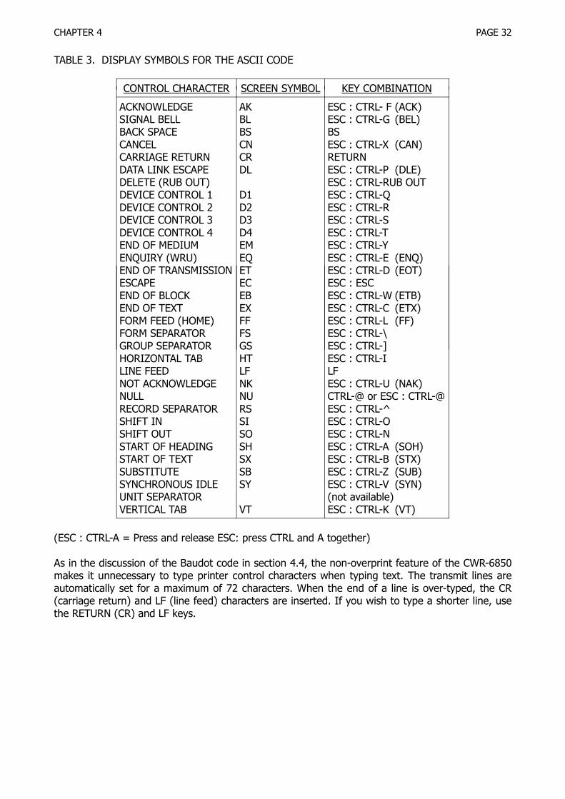
The CWR-6850 will transmit and receive a full ASCII character set, including upper and lower caseletters, all punctuation and symbols, and all control codes with the exception of the "US" (UnitSeparator) code (001 1111). Each ASCII character and control code has a unique symbol that isdisplayed on the CWR-6850 screen. These symbols are shown in Table 3. The key combinationsused to produce the ASCII control codes are also shown in Table 3. Note that it is necessary topress the "ESC" key before typing the "CTRL-n" combination since many of the "CTRL-n" keys areused for CWR-6850 control. A complete listing of the ASCII codes is shown in Table 4.
Often, it is desirable to be able to transmit an abridged form of the ASCII code, using only uppercase (capital) letters. This feature, called CAPS LK, is turned on with the LOCK / UOS ON switch. InASCII, this switch selects CAP LK when it is depressed. This feature effects both the transmit andreceive sections of the CWR-6850 - only upper case ASCII characters may be received and trans-mitted when the LOCK switch button is in.
CHAPTER 4 PAGE 32
TABLE 3. DISPLAY SYMBOLS FOR THE ASCII CODE
CONTROL CHARACTER SCREEN SYMBOL KEY COMBINATION
ACKNOWLEDGESIGNAL BELLBACK SPACECANCELCARRIAGE RETURNDATA LINK ESCAPEDELETE (RUB OUT)DEVICE CONTROL 1DEVICE CONTROL 2DEVICE CONTROL 3DEVICE CONTROL 4END OF MEDIUMENQUIRY (WRU)END OF TRANSMISSIONESCAPEEND OF BLOCKEND OF TEXTFORM FEED (HOME)FORM SEPARATORGROUP SEPARATORHORIZONTAL TABLINE FEEDNOT ACKNOWLEDGENULLRECORD SEPARATORSHIFT INSHIFT OUTSTART OF HEADINGSTART OF TEXTSUBSTITUTESYNCHRONOUS IDLEUNIT SEPARATORVERTICAL TAB
AKBLBSCNCRDL
D1D2D3D4EMEQETECEBEXFFFSGSHTLFNKNURSSISOSHSXSBSY
VT
ESC : CTRL- F (ACK)ESC : CTRL-G (BEL)BSESC : CTRL-X (CAN)RETURNESC : CTRL-P (DLE)ESC : CTRL-RUB OUTESC : CTRL-QESC : CTRL-RESC : CTRL-SESC : CTRL-TESC : CTRL-YESC : CTRL-E (ENQ)ESC : CTRL-D (EOT)ESC : ESCESC : CTRL-W (ETB)ESC : CTRL-C (ETX)ESC : CTRL-L (FF)ESC : CTRL-\ESC : CTRL-]ESC : CTRL-ILFESC : CTRL-U (NAK)CTRL-@ or ESC : CTRL-@ESC : CTRL-^ESC : CTRL-OESC : CTRL-NESC : CTRL-A (SOH)ESC : CTRL-B (STX)ESC : CTRL-Z (SUB)ESC : CTRL-V (SYN)(not available)ESC : CTRL-K (VT)
(ESC : CTRL-A = Press and release ESC: press CTRL and A together)
As in the discussion of the Baudot code in section 4.4, the non-overprint feature of the CWR-6850makes it unnecessary to type printer control characters when typing text. The transmit lines areautomatically set for a maximum of 72 characters. When the end of a line is over-typed, the CR(carriage return) and LF (line feed) characters are inserted. If you wish to type a shorter line, usethe RETURN (CR) and LF keys.

CHAPTER 4 PAGE 33
TABLE 4 ASCII DATA CODE
BITS 7 0 0 0 0 1 1 1 1 NOTES: 6 0 0 1 1 0 0 1 1 Mark = "1"4 3 2 1 5 0 1 0 1 0 1 0 1 = TTL high
0 0 0 0 NUL DLE SPC 0 @ P ' p Space = "0"0 0 0 1 SOH DC1 ! 1 A Q a q = TTL low0 0 1 0 SIX DC2 " 2 B R b r0 0 1 1 ETX DC3 * 3 C S c s0 1 0 0 EOT DC4 $ 4 D T d t0 1 0 1 ENQ NAK % 5 E U e u0 1 1 0 ACK SYN & 6 F V f v0 1 1 1 BEL ETB ' 7 G W g w1 0 0 0 BS CAN ( 8 H X h x1 0 0 1 HT EM ) 9 I Y i y1 0 1 0 LF SUB # : J Z j z1 0 1 1 VT ESC + ; K [ k 1 1 0 0 FF FS , < L \ l |1 1 0 1 RTN GS - = M ] m 1 1 1 0 SO HS . > N ^ n1 1 1 1 SI US / ? O _ o RBO
ACK = acknowledge HT = horizontal tab BAUD CHAR/ SELECTBEL = signal bell LF = line feed RATE SEC. PULSEBS = back space NAK = not acknowledge (ms)CAN = cancel NUL = null 45.45 4.13 22.00DC1 = device control 1 RS = record separator 50.00 4.55 20.00DC2 = device control 2 RTN = carriage return 56.92 5.17 17.57DCS = device control 3 RBO = RUB OUT = DEL 74.20 6.75 13.47DC4 = device control 4 SI = shift in 110.0 10.0 9.09DLE = data link escape SO = shift out 300.0 30.0 3.33EM = end of medium SOH = start of headingEOT = end of trans. SIX = start of textESC = escape SUB = substituteETB = end of block SIN = synchronous idleETX = end of text US = unit separator Transmission bit order:FF = form feed (home) VT = vertical tab bit 1 to bit 7FS = form separator ENQ = enquiry = WRU bit 8 = even parityGS = group separator SPC = space bar
The KOS (Keyboard Operated Switch) feature may be used to automatically control the transmit-receive circuitry of the station. The KOS transistor switch will turn-on the transmitter whenevertyped text is available for transmission and the transmit output of the CWR-6850 is enabled (useAUTO switch position and "CTRL-A" (or "CTRL-X") as explained in sections 4.2 and 4.4).
4.7 HDX / FDX Operation
The CWR-6850 may be operated in either a half-duplex (HDX) or full duplex (FDX) transmit con-nection, selected with the RX / TAPE switch. Normal amateur RTTY communications are usuallyconducted with equipment connected for half duplex operation. A full duplex connection is oftenused between a computer and a terminal.

CHAPTER 4 PAGE 34
With a half duplex connection, all transmitted text from the CWR-6850 may be seen on the screenbefore and after it has been transmitted. All of the features of the CWR-6850 may be used withhalf duplex. However, the CWR-6850 may only receive or transmit one at a time.
When full duplex is chosen, the CWR-6850 can receive and transmit text simultaneously. However,transmitted text will no longer be displayed in the receive section of the screen; it will, however,appear in the transmit screen area as usual. Typical full duplex connections with a computer usual-ly include a computer-generated "echo" back to the receive display or printer, showing the charac-ters as received and interpreted by the computer; transmission errors are therefore soon noticed.The complete ASCII and Baudot character sets may be transmitted in FDX mode.
When using full duplex, use the AF IN - TAPE connector for received data; either the AFSK OUT -TX or AFSK OUT - TAPE connector may be used for transmitted tones. The FSK TTL - IN and OUTconnectors may be used if the FSK DEMOD switch is set to EXT.
The "CTRL-E" echo command allows some interesting variations of full duplex. When the RX-TAPEswitch is set to TAPE and "CTRL-E" is used, received data is loaded into the transmit buffer andyou may then retransmit this received data. If the switch is set to RX position and "CTRL-E" isused, text typed on the keyboard is entered into the transmit buffer, transmitted, and reloadedback into the transmit buffer, forming a continuous loop.
4.8 The KOS Feature
The KOS (Keyboard Operated Switch) feature of the CWR-6850 allows automatic control of thetransmit-receive circuits of the station in much the same manner as the SSB VOX circuit. Select theKOS feature by setting the SEND-AUTO-RECEIVE switch to AUTO (center position). When you havepretyped your text and are ready to start transmitting, type "CTRL-A". The transmitter will turn onand, after a short delay, transmit the typed text. After all of the text has been transmitted, and af-ter another short delay, the transmitter will turn off. If you type any more text, the transmitter willturn on again and that text will be transmitted. To pretype without further transmitting, type"CTRL-A" again. The "A" on the status line of the screen shows if the automatic KOS feature is ac-tive.
The on-off KOS control of the transmitter may be controlled manually with the "CTRL-X" command(shows "X" on status line when active). The "CTRL-X" command turns the transmitter on for aslong as the "X" is shown on the status line; you must type another "CTRL-X" to turn off the trans-mitter, whether there is text to be transmitted or not. More details regarding the "CTRL-A" and"CTRL-X" commands are given in section 4.2.
The KOS switch transistor is NPN and will therefore key only transmitters with a positive voltage tx-rx control line (push-to-talk line, usually). If your transmitter has a negative voltage control line(the Drake M is an example), it will be necessary to use a relay or additional transistor switch be-tween the CWR-6850 KOS output and the transmitter. This variation is discussed in Section 5.1.
The SEND-AUTO-RECEIVE switch parallels the KOS (SW-OUT REMOTE) jack when it is in SEND po-sition, manually turning on the transmitter.

CHAPTER 5 PAGE 35
Figure 4 – Connections To The CWR-6850

CHAPTER 5 PAGE 36
CHAPTER 5CONNECTIONS TO THE CWR-6850
This section of the CWR-6850 manual discusses how to connect the Telereader to your equipment.Section 5.1 will discuss basic connections you may wish to make in a typical radio amateur station.Later sections of this chapter discuss specialized connections.
5.1 Normal Amateur Station Connections
The basic minimum connections required for a transmit-receive station connection have beenshown in Figure 2 in Chapter 2; more elaborate connections are shown in Figure 4. The HAL cableset "C2" makes the simple connections or you may fashion your own cables. The "basic requiredconnections" of Figure 2 are:
1. A good RF ground between all components of the system. Use heavy wire or 1/4" shield braid.2. A shielded audio cable between the receiver speaker output and the CWR-6850 AF IN - RX
connector. A high fidelity phono cable will do nicely.3. A shielded audio cable between the transmitter microphone audio input and the CWR-6850
AFSK OUT - TX connector. A stereo phono cable can be used for this and the KOS connectiondescribed next. Note that the phono connector(s) will probably need to be cut-off on the trans-mitter end of this cable and the correct microphone plug connected. Consult your owners man-ual for the correct connector and pin numbers. The output level from the AFSK OUT jacks maybe adjusted if necessary with the AFSK GAIN control. Consult your transmitter manual and in-sert a series capacitor if required as noted in Section 2.1.
4. A shielded cable between the transmitter microphone push-to-talk (PTT) input and the CWR-6850 SW. OUT - REMOTE connector (KOS for Keyboard Operated Switch). The other half of thestereo cable used for transmit audio can be used for this connection. As above, consult thetransmitter manual for connector and pin numbers. The NPN transistor KOS switch will onlyswitch positive voltage PTT circuits directly; negative voltage PTT circuits will require an exter-nal relay. This relay may be connected as shown in Figure 5.
CONNECTION KOS CIRCUIT (POSITIVE VOLTAGE)
CONNECTION TO KOS CIRCUIT (NEGATIVE VOLTAGE)
Figure 5 – KOS Circuit Connections

CHAPTER 5 PAGE 37
5. A shielded cable between the transmitter Morse code key input and the CWR685Q SW. OUT -CW connector. Either a positive or negative voltage keying circuit may be connected to thisjack. Again, this cable can be a high fidelity phono cable with the transceiver plug end modifiedas appropriate. This connection can often be combined in a stereo cable with the receiver au-dio cable (item 2) when connections are made to a transceiver.
6. Connect the keyboard to the CWR-6850 with the cable and connector furnished.7. Connect the CWR-6850 to a DC power source capable of +12 to +14.5 VDC output with a 1.6
Ampere load.
*** CAUTION ***
Be sure that you connect the RED wire to the positive terminal and the BLACK wire to the negativeterminal. Reverse power connection may damage both the CWR-6850 and the DC power source!
If you use an AC power supply to generate the +12 VDC, use a grounding type of AC connector orprovide a separate power ground return for the power supply to prevent any electrical shock.
5.2 Use of the TTL Data Connections
The CWR-6850 includes input and output connectors for use with TTL data devices ("FSK TTL IN"and "FSK TTL OUT"). These I/O connections can be used with any TTL compatible device. The TTLvoltage standard is as follows:
MARK = +2.7 volts (+5.0 volts maximum)SPACE = +0.6 volts (0.0 volts minimum)UNDEFINED: +0.6 volts to +2.7 volts
Notice that the voltage levels of the TTL standard are NOT compatible with those of RS232 dataconnections. Do not be misled by some claims of direct TTL - RS232 compatibility; damage may becaused to one or both units! The TTL I/O connections may be used for connection to printers,computers, or other TTL data devices.
The TTL output is always available for all ASCII and Baudot signals; the TTL input is selected withthe FSK DEMOD. - INT / EXT switch on the rear panel. Leave the switch in the "INT" positionwhenever you wish to use the internal demodulator for receiving Baudot or ASCII signals.
5.3 Use of the SW-OUT FSK Connection
Some amateur transmitters have provision for direct FSK keying of an internal oscillator. These FSKinputs typically require that a control line be switched between open circuit and ground for themark and space RTTY conditions. The SW-OUT FSK rear panel jack may be used to control suchtransmitter inputs. The internal transistor switch of the CWR-6850 has maximum ratings of +100VDC and +100 mA DC; negative voltages can not be switched. The SW-OUT FSK standard configu-ration shows an "open circuit" for mark condition and a "closed circuit" (transistor switch "on") forspace. However, an internal jumper of the CWR-6850 allows this polarity to be reversed, settingmark to "on" and space to "off". Refer to section 6.4 for location of the jumper and connections tobe made. It is not recommended that you use this SW-OUT FSK jack to key a high-voltage RTTYloop circuit; use an optical isolator driven from the TTL output instead.

CHAPTER 5 PAGE 38
5.4 Connection of a Different Keyboard
The CWR-6850 is furnished with a reliable full-ASCII keyboard which should give long hours of sa-tisfactory performance. However, it does connect to the CWR-6850 using a standard parallel-ASCIIinterface and another keyboard (or a computer) may be connected in its place. The following arethe specifications to be observed when connecting to the keyboard connector:
1. The keyboard must be capable of generating all standard ASCII codes and must generate posi-tive 7-bit parallel output data and a 1 bit negative strobe pulse; set D8 to a logic "low".
2. The keyboard must operate from +5 VDC and require less than 250 mA DC.3. The keyboard connector is a HIROSE 24 Pin Connector, HAL P/N 332-24000.4. The pin connections are:
1 - Ground 7 - D6 132 - D1 8 - D73 - D2 9 - D8 to NOT USED4 - D3 10 - NOT-STROBE5 - D4 11 - NOT-ACK6 - D5 12 - +5V 24
The NOT-ACK signal is not used in the CWR-6850 on the present keyboard. When interfacing to acomputer, check the response from NOT-ACK before entering data.
5.5 Connection of an ASCII Printer
A serial ASCII data printer may be used with the CWR-6850 by connection to the PRINTER connec-tor. This output is a parallel, Centronics-compatible interface connection. The specifications of theprinter connection are:
Connector: HIROSE P-1612-BAC 12-pin plug (HAL 332-12000)Wire: 12 Conductor cable (shielding recommended); 5 ft.
PIN USE PIN USE
123456
GNDBUSY (NOT-RDY)NOT-ACKD8 (MSB)D7D6
789101112
HOT-STROBED1 (LSB)D2D3D4D5
Use a printer that includes a one-line buffer register and will do automatic line feed operationswhen either the buffer is full or the ASCII line feed character is received (0A HEX). The output ofHOT-STROBE is a negative pulse of approximately 1.2 µsec. duration. The NOT-ACK input is notread; data is output to the printer when BUSY (NOT-RDY) is in a "low" TTL state. Data output islatched just before the next NOT-STROBE output pulse. The D8 output condition is set to a TTL"low". The output is parallel 7-bit ASCII. The contents of the printer output FIFO register are dis-played on the top two lines of page 2 of the display.
Data to the printer is turned on and off with the "CTRL-P" command. When the printer is active aletter "P" will appear on the status line. The printer provides print-out of data AS IT IS RECEIVED.When you use full duplex (normal amateur use), received data is printed as it is received. Sincethe transmitted text is repeated or "echoed" in the receive buffer, it too is printed. If full duplex isused, only receive data will be printed. Refer to the discussions of section 4.7 for more informationconcerning full and half duplex operations. Since most printers use a line buffer, text will not be

CHAPTER 5 PAGE 39
physically printed until an entire RECEIVED line is complete (as distinguished from a 32 characterdisplay line). Some printers allow modification of the print format when some ASCII control codesare received. All control codes to the printer except LF are normally suppressed to avoid print for-mat changes on received text (or noise). The commands to the print can be enabled, however, bytyping "CTRL-C"; a second "CTRL-C" disables the commands.
5.6 Connection of an Audio Tape Recorder
An audio tape recorder may be connected to the AFSK OUT - TAPE and AF IN - TAPE connectors ofthe CWR-6850 for recording and playing back of messages. The AFSK OUT - TAPE connector fur-nishes the CWR-6850 transmit tones to the tape recorder input (microphone or auxiliary input). Ontransmit, these tones are keyed by transmit data, such as that typed on the keyboard. Thus, youcan make-up long "brag-tapes" or messages on the CWR-6850 screen and record them as you"transmit" them. You may prevent the transmitter from turning on by temporarily disconnectingthe cable to the SW.OUT - REMOTE Jack (KOS to PTT connection). The TAPE OUT level may be ad-justed with the AFSK GAIN rear panel control.
To transmit tape recorded text, select TAPE on the RX/TAPE switch (button in), type "CTRL-E", turnthe transmitter on with the SEND or AUTO switch position (use CTRL-A or CTRL-X as per discus-sions in section 4.2), and start the tape in the playback mode. The recorded tones are now fed-through the CWR-6850 receive demodulator, filtered and detected, and then modulate the CWR-6850 transmit output tones (and TTL output). Thus, the tape data is reprocessed before transmis-sion, helping to eliminate some of the distortion otherwise caused by tape wear and stretch. Whenthe taped message stops, type CTRL-E again to end the echo-back feature.
The connection of the tape recorder to the CWR-6850 is shown in Figure 5. Use shielded cables forthese connections; include RF and safety grounds to minimize any RF pickup in the tape recorder.
5.7 RTTY Tuning Oscilloscope Connections
In addition to all of the input/output (I/O) connections discussed above, you may also wish to usean external monitor scope for a RTTY tuning indicator. The OSCILLO (SPACE and MARK) connec-tors are provided for tuning indicator use. These output are the filtered signals present at the RTTYdemodulator discriminator circuits. The signals are approximately 8 VPP in amplitude and have aninternal impedance of approximately 200 kΩ. As shown in Figure 4, the standard convention is touse an X-Y oscilloscope with the MARK signal connected to the horizontal scope input and theSPACE to the vertical input. Since these signals have a relatively low output level, it is necessary touse an oscilloscope with amplifier stages in both the vertical and horizontal sections. Use shieldedcable for these connections; be sure to include safety power as well as RF ground connections.
The display on the oscilloscope screen for correct receiver tuning will be of the crossed-ellipsetype. Correct tuning is indicated when the horizontal ellipse (mark signal) and the vertical ellipse(space) have maximum amplitude (length of the ellipse) and are orthogonal. The 170 Hz shift ellip-ses will be fairly wide and will not necessarily be at 90 degrees to each other - this is normal! Theellipses for the wider shifts (425 and 850) will be noticeably narrower and closer to a full 90 de-grees apart. With practice, the tuning scope provides the most accurate tuning indicator available.Properly interpreted, the scope patterns tell which direction to tune the receiver and whether thesignal shift matches that of the selected demodulator shift.

CHAPTER 5 PAGE 40
5.8 Using a Television Set or External Monitor
Although the internal cathode ray tube (CRT) of the CWR-6850 produces an excellent display, youmay wish to use an external TV Monitor or TV set to display the text; a larger monitor tube willgive a larger character size display. Any standard composite video monochrome TV monitor maybe connected to the VIDEO OUT connector on the CWR-6850 rear panel. The video output is 1VPP, composite video, 75 ohm impedance. Connection of an external monitor does not affect thedisplay on the internal CRT of the CWR-6850.
Some good quality black and white TV sets can be easily modified to serve as video monitors. Thechange does not affect normal operation of the set except that the video cable from the CWR-6850must be removed from the TV when the set is to be used to receive television programs. It is im-portant that the selected TV have adjustments available for both horizontal and vertical size. Nor-mal TV alignment results in "over-scan" of the viewing screen, preventing margin lines but also los-ing parts of the picture at the edges and corners. To avoid losing characters of the CWR-6850 dis-play along the corners and edges, it may be necessary to "shrink" the size of the TV raster withthe width and height controls. These adjustments will be made after the TV set is modified andwhen you can look at the CWR-6850 video output.
*** CAUTION ***
DO NOT attempt to use as a monitor any television receiver in which one side of the AC line is con-nected to the chassis or circuit ground of the set unless you supply AC power to the set throughan isolation transformer.
The modification is simply a matter of capacitively coupling the external video signal to the inputof the first video amplifier stage in the TV set. Figure 6 shows a typical transistor TV video circuit.Although the component values and the biasing scheme may be slightly different in your set, thecircuit should be essentially as shown. The CWR-6850 video signal is injected at point A.
The modified circuit is shown in Figure 7. Connect the negative end of a 100 µF, 16 V electrolyticcapacitor to the base of the first video amplifier transistor. Mount a UHF (or BNC) video connectoron the cabinet as close as possible to the capacitor connection. Connect the center pin of the coaxconnector to the positive end of the electrolytic capacitor. Use hook-up wire if the connection isless than 6 inches; use a small coaxial cable such as RG174 for longer connections.

CHAPTER 5 PAGE 41
Figure 6 – Typical Video Detector
Figure 7 – Modified Video Detector

CHAPTER 5 PAGE 42
5.9 RF-Induced Problems
The CWR-6850 is designed to operate in close proximity to radio frequency transmitting and receiv-ing equipment. However, under certain conditions in an RF-saturated environment, the CWR-6850may be susceptible to HP-induced interference. This may manifest itself in any of a number ofways, such as partial or complete lack of response to switches or keyboard operations, or erraticbehavior of the video display.
The first thing that should be checked if RF problems are suspected is the GROUND system. Thetransmitter should be properly grounded for RF (in addition to an electrical safety ground) and allother station equipment grounds should be connected to the transmitter chassis. The RF groundshould consist of a short length of heavy copper wire or braid terminated at a good earth ground(ground rod, cold water pipe, etc.). If a water system ground is used, be sure that the pipes are100 percent metal from the connection point to the water mains - plastic plumbing will break theground path. If the distance between your transmitter and ground connection is more than a quar-ter wavelength at the highest operating frequency, make the ground wire an integral number ofhalf-wavelengths long. If you plan to operate 10 and 15 meters, you may need to run separateground wires for each band.
Stations located on the second floor of wood frame houses can present special problems for RFgrounding. One technique that has worked well when none of the usual ground returns work is tospread copper screen material on the floor of the room under the operating position. The equip-ment ground is then attached to the screen with one or more low inductance leads. The screencreates an "artificial" ground plane in the studio. A carpet is usually placed over the screen to im-prove the appearance of the room! Consult any of the amateur handbooks or antenna books for amore in-depth discussion of grounding techniques.
The best way to confirm that a problem is caused by RF-induction is to temporarily eliminate thesource. This may be done in stages, starting with a partial reduction in exciter drive, and endingwith transmitter shut-off. Since RF energy may be induced in the CWR-6850 through several paths,connecting the transmitter to a dummy load may not eliminate all RF related problems, althoughthis is an excellent first step in verifying RF problems.
(A)

CHAPTER 5 PAGE 43
PLACE RF CHOKE CLOSE TO REAR PANEL OF EQUIPMENT
(B)
Figure 8 – RFI Reduction Techniques
Radiation of RF energy from linear amplifiers, antenna tuners, coaxial switches, monitor scopesand interconnecting coaxial cable Jumpers is also possible. In fact, it is this type of radiation that ismost likely to be coupled into nearby I/O and power cables of the CWR-6850. To locate the pointor points of radiation, experiment with different cable arrangements to see if the RF-induced prob-lem can be eliminated by reducing coupling between any of the CWR-6850 cables and nearby co-axial lines carrying RF power. Figure 8A shows several cable arrangements, both good and bad,showing how to keep RF coupling to a minimum. Figure 8B shows how to use high-mu (950 -2000) ferrite toroids or rods to choke the flow of RF on audio and control lines.
If cable rearrangement doesn't yield positive results, then begin eliminating pieces of equipmentand sections of coaxial cable until the transmitter is connected directly to a shielded dummy load.As each piece of equipment is removed from the transmission line, check to see if the RF-relatedproblems have diminished or disappeared. If the RF problem persists with the exciter connecteddirectly to a dummy load, reduce the drive level to see if that eliminates the problem.
If operation into a dummy load does not significantly reduce the RF-related problems, disconnectall I/O cables from the CWR-6850. Test the operation while it is connected only to AC power. At thesame time, enable the transmitter so that it sends a CW signal into a dummy load. If RF problemsare still present, then RF energy is probably being introduced to the CWR-6850 through the powercord by way of the common AC mains power line. This is usually indicative of poor AC-line filteringin the radio transmitter power supply section. Figure 9A shows a common by-pass filter methodused in many transmitters. Figure 9B shows a "brute-force" AC line filter that can be added to thetransmitter or other equipment to eliminate the flow of RF on the AC power line.
In addition to the liberal use of RF by-passing capacitors on station equipment, the use of certainantennas may offer reduced levels of RF in the radio room in many cases. Whenever possible, useRESONANT dipole, vertical, quad, or Yagi antennas and try to achieve a good impedance match ATTHE ANTENNA instead of relying on an antenna tuner. Random-length wire antennas and othersthat require extensive antenna tuning are more likely to create high levels of RF within the vicinityof the operating position.
The location of the transmitting antenna with respect to the radio room also has an affect on theRF energy that is coupled into interconnecting cables. Apartment dwellers may have the most diffi-culty achieving a good installation since many times an indoor antenna is the only type allowed.Where outdoor antennas are allowed, they should be placed as high as practical. Hot only will thisprovide for better reception and transmission, but it will also reduce the level of RF in the shack.

CHAPTER 5 PAGE 44
Also, if possible, avoid bringing an end of a half-wave dipole in close proximity to the operating po-sition; there is a high voltage field at the ends of the dipole that may be hard to shield.
(A)
(B)
Figure 9 – Power Line Filters
In general, a shielded, coaxial cable feedline with low SWR is much preferred over open wire, twin-lead, or single wire feed systems. The self-shielding property and lower voltages present act tomake the coaxial feedline much less susceptible to radiation of RF energy in the shack rather thanat the antenna. RF energy may also be conducted back to the station by conduction down the out-side of the coaxial cable shield. This may be a particular problem with half-wave dipoles on 40 and80 meters that are center-fed with only coaxial cable. A balun at the antenna tends to reduce thisproblem. Also, dress the coaxial cable from the balun so that it drops perpendicular to the dipole,rather than parallel. In stubborn cases, you may find that dropping the coaxial cable clear to theground and burying it (5 or 6 inches) for the horizontal run to the shack my help reduce RF cou-pling considerably. This technique has worked particularly well for second-story station installa-tions. As an alternate to the balun, construction of an RF choke out of the Coax itself is sometimeseffective; wind six or more turns of the coaxial cable in a six inch diameter coil. Place the coil atthe antenna and wrap it with electrical tape to hold its shape. If there is a moderate to high SWRon the line (2:1 or more), you may find that varying the length of the line helps, although this is apoor substitute for a properly matched antenna.

CHAPTER 5 PAGE 45
Experience has shown that the TV monitor itself may be a source or conductor of RF interference.Various circuits of the TV monitor (particularly the sweep circuits) can and do generate RF interfer-ence which may be heard in the receiver. Also, the video output to the monitor is a wide band-width digital signal with rich harmonic content as is required to produce the crisp character display.If the TV set is poorly shielded (not at all in some plastic-cabinet models) or lacks proper powerline by-passing, the RF from the monitors circuits or from the video output may escape to causereceiver interference. Also, RF from the transmitter may enter the monitor and. disrupt the monitoror CWR-6850 operation. This may be quickly tested by simply disconnecting the video cable fromthe CWR-6850. There is no substitute for good shielding and by-passing; metal cabinet monitorsare highly recommended!
When the CWR-6850 is used in a mobile or portable installation, trouble may be experienced fromtransients caused by the battery-charging system. These transients may be minimized by connect-ing the CWR-6850 power cord directly to the storage battery terminals, avoiding connections tothe vehicles DC terminal block. Any voltage drop between the battery and terminal block may alsoinclude the transient spikes. It may be necessary to install additional filtering on the DC leads tothe CWR-6850 and some on automotive accessories (such as blower and wiper motors) to elimi-nate such problems. Consult the ARRL Radio Amateur's Handbook for more information.
The CWB6850 has been tested and is verified by HAL Communications Corp. to be in compliancewith Part 15, Subpart J of the FCC Rules And Regulations, Class B computing device. The followingtext is a requirement of that regulation:
"This equipment generates and uses radio frequency energy and if not installed and usedproperly, that is, in strict accordance with the manufacturer's instructions, may cause inter-ference to radio and television reception. It has been type tested and found to comply withthe limits for a Class B computing device in accordance with the specifications in Subpart Jof Part 15 of FCC Rules, which are designed to provide reasonable protection against suchinterference in a residential installation. However, there is no guarantee that interferencewill not occur in a particular installation. If this equipment does cause interference to radioor television reception, which can be determined by turning the equipment off and on, theuser is encouraged to try to correct the interference by one or more of the following meas-ures:
reorient the receiving antennarelocate the computer with respect to the receivermove the computer away from the receiverplug the computer into a different outlet so that computer and receiver are on differentbranch circuits.
If necessary, the user should consult the dealer or an experienced radio/television techni-cian for additional suggestions. The user may find the following booklet prepared by theFederal Communications Commission helpful:
"How to Identify and Resolve Radio-TV Interference Problems." This booklet is availablefrom the US Government Printing Office, Washington, DC 20402, Stock No. 004-000-00345-4."
In addition, the following rear-panel label is located on the CWR-6850 rear panel:
"This equipment has been tested and found to comply with the technical specifications inPart 15 of FCC Rules for a Class B computing device."

CHAPTER 5 PAGE 46
Also, the following FCC text applies to use of peripherals attached to the CWR-6850:
"WARNING: This equipment has been verified to comply with the limits for a Class B com-puting device, pursuant to Subpart J of Part 15 of FCC Rules. Only peripherals (computerinput/output devices, terminals, printers, etc.) certified to comply with the Class B limitsmay be attached to this computer. Operation with non-certified peripherals is likely to resultin interference to radio and TV reception."

CHAPTER 6 PAGE 47
CHAPTER 6IN CASE OF DIFFICULTY
This section of your user's manual will discuss in general terms how to keep your CWR-6850 in topoperating condition and typical operating problems you might encounter (and some solutions). Cir-cuit description, repair procedures, and schematic diagrams are included in the separate CWR-6850 CUSTOMER MAINTENANCE MANUAL, available separately from HAL Communications Corp. orits dealers.
6.1 Care and Feeding of Your CWR-6850
Your CWR-6850 is the latest of many generations of terminals sold by HAL Communications. In ev-ery way, it has been designed, constructed, and tested to assure years of trouble-free operation.However, there are a number of simple procedures that you, the user, can follow to further im-prove the reliability, performance, and lifetime of the terminal. The following suggestions are of-fered to help preserve a long operating life for your CWR-6850.
Environment:
Electric equipment is very susceptible to variations in temperature, relative humidity, and to dustand dirt accumulations. The CWR-6850 will operate in normal room-temperature environments andshould be as tolerant of temperature extremes as you are while operating it. However, in advertentblockage of the ventilating holes in the cabinet will cause the INTERNAL temperature of the termi-nal to rise considerably above the ambient room temperature and may in fact cause circuit failure.Also, accumulations of dust or dirt, particularly when accompanied by high humidity conditions,can also cause overheating and may result in long-term corrosion of the internal circuitry. There-fore, try to position the terminal so that its ventilating holes are not obstructed and try to avoid ex-tremely dusty or dirty environments. On the other hand, the solid-state components in the CWR-6850 are designed to operate at considerably higher temperatures than we humans; do not beoverly disturbed if the cabinet of the CWR-6850 (particularly the rear panel) operates quite warmto the touch. This internal heat often helps to "dry-out" humidity in the cabinet.
In the normal course of operation, the terminal and its display may attract a build-up of dust orsmoke "haze". This may be expected even in the cleanest areas, particularly if tobacco smoking isprevalent. The display screen, because of the air flow around it and the high voltage applied to theCRT, actually attracts particulate matter from the air. This causes over a period of time what mayappear to be a gradual fading of the screen intensity as well as de-focusing of the characters.Therefore, the face of the CRT should be cleaned often.
Be careful when cleaning any plastic parts as they scratch easily! Cleaning materials available forphonograph records are usually excellent for cleaning plastic, but may not be strong enough to dothe job if too much dirt has accumulated.
The keyswitches in an electronic keyboard seem to be particularly vulnerable to humidity and par-ticulate air contaminants. Experience has shown that keyswitch failures are considerably more like-ly in equipment used in a high humidity location (in a basement, for example) ; even more so ifthe basement operator also smokes! The keyswitches in the keyboard are commercial qualityswitches that should last for many years. However, they are essentially mechanical parts, unsealedfrom the environment and will tend to be much more susceptible to this type of problem than anyother CWR-6850 part.

CHAPTER 6 PAGE 48
Electrical Connection:
All electrical connection points of the CWR-6850 have maximum voltage and current ratings as giv-en in this manual. If these ratings are exceeded for even a short period of time, considerable dam-age to the terminal may result. Therefore, be very careful KNOW the ratings of the CWR-6850 andthe characteristics of any other equipment before making connections. Some common causes ofelectrical failures have been found to be:
A. Inadequate grounding, causing RF interference problems as well as sensitivity to AC power linetransients.
B. Damage from lightning, or other transients on the power line or" station antenna system. Agood lightning protection system may help, as will disconnecting the terminal during electricalstorms. However, such things are unpredictable and the CWR-6850 is no more susceptible tosuch problems than other electronic equipment in the station.
C. Improper connections to high voltage devices or to equipment with inadequate safety grounds.The CWR-6850 does NOT include a high-voltage RTTY loop keying circuit and NONE of its rearpanel jacks should be connected to high voltage loop circuits without the use of isolation devi-ces such as optical isolators or relays. Be sure that all devices plugged into the AC mains havesafety grounds attached to them. AC line by-pass capacitors in a piece of equipment maycause the cabinet of that equipment to "float" at an AC potential sufficiently high that damagemight be done to the CWR-6850 when the equipment is connected. CONNECT THE GROUNDSFIRST - THEN CONNECT TO POWER!
6.2 Typical Operational Problems
Because a large number of features are offered in the CWR-6850, it is by nature a complicated de-vice. Therefore, there may be times when it first appears that the terminal has either quit com-pletely or gone off to "do its own thing". If some of the circuitry has failed, you may well get suchsymptoms. However, most often when a new owner finds the terminal "unresponsive", it is actuallydoing what it has been instructed to do. Familiarity with the CWR-6850 controls will quickly reducethe chances of "cockpit error" during terminal operation.
The status line and front panel switch position are the best keys to what is happening in the CWR-6850. Often, mistyping one key for another may cause a result entirely different from that intend-ed. Some of the more confusing conditions you may encounter are:
1. Forgetting to terminate the programming of a HERE IS message with the RUB OUT key. If youforget to end the HERE IS programming, further typed text will continue to be entered into theHERE IS memory until all 61 memory locations are full. At this point, further typing is not ac-cepted by the CWR-6850 and it appears to be in a non-functioning condition. LOOK AT THESTATUS LINE! The "W1" next to the reverse video page "3" shows that the terminal is in writemode for HERE IS 1. Look at the displayed text in HERE IS 1, use the BS key to delete the ex-tra characters you have typed, and end the HERE IS programming with the RUB OUT key. The"W1" will now disappear, the original display page will return to the screen, and the CWR-6850will function correctly.
2. The transmit buffer area of the screen will register the presence of a carriage control character(CR or LF), but will NOT perform the operation on this section of the screen; a LF will not shiftthe keyboard entry point to the next displayed line of the transmit buffer. The appropriate char-acters will be transmitted, however, in the sequence in which they were entered and the opera-tions do appear in the RECEIVE section of the screen as they are transmitted (half duplex oper-ation only). The transmit buffer display area is strictly linear, showing each key typed.
3. When word mode (CTRL-Y) and automatic control (CTRL-A) are used, the transmitter will turnon and off between words after the pre-typed text has been transmitted. This may cause loss

CHAPTER 6 PAGE 49
of characters at the receiving station (particularly if a repeater is used). Use CTRL-X and contin-uous mode if this is a problem.
4. The CWR-6850 may be operated in either half or full duplex modes as explained in section 4.7.However, transmitted text is ONLY "echoed" in the receive section of the display in half duplex.
5. The CWR-6850 will only receive correctly if ALL the switches are set correctly. Refer to Chapter3 for correct starting points for switch selection. The following are general guidelines:
a. CW RECEIVE: CW/RTTY - button outRX/TAPE - button outSEND/RECEIVE - RECEIVE or AUTO (CTRL-X Off)
b. RTTY RECEIVE: CW/RTTY - button inASCII/BAUDOT - select code (BAUDOT, usually)LOCK-UOS ON - ON (button in)NOR/REV - NOR (button out; if LSB used)BAUD - select rate (45.5, usually)SHIFT - select shift (170, usually)TONE - high for VHP; either for HFRX/TAPE - RX (button out)SEND/RECEIVE - RECEIVEFINE - "0" (center detent)
6. Look at the status line. The presence of one or more letters on this line indicates that a featurehas been activated by the corresponding control command. A complete list of the control com-mands, their action, and the corresponding status indicator is shown in Chapter 7. Often, aconfusing state may have been caused by accidental typing of a control command. Above all,be careful when using the "CTRL-L:RETURN" key sequence. If invoked, the CWR-6850 is ex-pecting to load the HERE IS memories from tape. The ONLY recovery is to load from the tapeor cycle the power on and off! See section 4.3 for further information. The "CTRL-S:RETURN"tape save command will likewise yield confusing results, but will recover after the total con-tents of all six HERE IS memories have been transmitted.
7. The RESET button will clear the entire receive display area, clear the printer output buffer, andclear the tape save buffer. Use this control carefully, but in preference to cycling the power offand back on.
6.3 Repair Procedures
In the event that your CWR-6850 develops a malfunction, the first step is to carefully note all ofthe symptoms of the problem. Statements such as "BROKEN" or "DOESN'T WORK" are of littlehelp to the service technician, and usually lead to longer repair times than might otherwise be re-quired. Try to provide as much information concerning the failure as you can before you contactyour dealer. By all means, consult your dealer before calling the factory; he may be able to fix theunit locally and avoid the shipping and delay times.
The following are some of the things that will concern the dealer or factory:

CHAPTER 6 PAGE 50
1. Model number2. Serial number3. How long have you owned it?4. Where did you purchase it (dealer's name?5. If purchased used, who was the previous owner? (Used to refer to any previous repair
history on that unit.)6. What terminal modes, rates, codes, and conditions are associated with the failure?
Does it happen only in receive, transmit, or both?7. Are there extenuating circumstances? (Lightning, spilled liquids, dropped unit?)8. Is the problem confined to a particular unit? (CWR-6850, keyboard?)9. Is there anything else you can add to the description that you think might be useful?
AFTER you have determined answers to the above, contact your dealer and discuss the problemwith him. If he indicates that he will be unable to assist you, the unit should be returned to theHAL factory for repair. Before returning the unit to the factory, either you or the dealer should calland receive factory return authorization so that we may expect the unit in shipping and be pre-pared to work on it when it arrives. Whenever possible, return the unit via UPS to the factory ad-dress below, insuring it for the full value. The shipping cost to the factory should be paid by you;the return shipping costs from the factory (48 contiguous states only) are paid by HAL (warrantyrepairs only). The factory "ship-to" address is:
HAL COMMUNICATIONS CORP.1201 W. KENYON ROADBOX 365URBANA, ILLINOIS 61801ATTENTION: REPAIR DEPARTMENT
The one-year limited warranty (listed in full at the end of this manual) provides for repair of theCWR-6850 for a full year after purchase. The purchase invoice date from your dealer marks the be-ginning of the warranty period - save your copy of the invoice I Please read the warranty carefullyto determine the full extent of the privileges and limitations.
6.4 User Adjustments
Because of the complexity of the circuitry used in the CWR-6850, we do NOT recommend that youpersonally undertake repairs of the terminal circuit boards. However, there are a number of align-ment procedures that you may undertake if you have the test equipment available. DO NOT UN-DERTAKE ANY ADJUSTMENTS UNTIL YOU ARE SURE THAT UNDERSTAND THE ENTIRE PROCE-DURE. If in doubt, don't do it! (Ask your dealer or the factory for help.) The recommended mini-mum teat equipment is:
1. Audio Frequency Counter - high impedance input, 1 V or better sensitivity, count to 1MHz or higher.
2. Audio Frequency Oscilloscope - high impedance input, 1 V or better sensitivity, 1 MHz orgreater bandwidth.
3. Volt-Ohm-Milliammeter (VOM) - 20 kΩ/V or higher.4. Audio Frequency Oscillator - 500 ohm impedance, 10 mV to 1 V rms output, 500 – 3000
Hz adjustable frequency.
Simplified layout drawings are shown in Figure 10 that give the locations of various variable resis-tors (VR-n), test points (TP-n), and user jumper locations (JP-n). Note that there are numerous ad-ditional jumper locations on the circuit boards that should not be disturbed from their factory set-tings.

CHAPTER 6 PAGE 51
There are four major sub-assemblies that make-up the CWR-6850:
1. The cabinet with its controls, connectors, and wire harnesses.2. The CRT display section.3. The digital circuit board (top board).4. The modem circuit board (bottom board).
Most of the following adjustments are located on one of the two circuit boards. It is NOT necessa-ry to remove any circuit boards to make these adjustments. You will, however, have to removeboth the top and bottom covers of the CWR-6850. Be careful to avoid misplacing any of the six-teen black screws that fasten the covers in place - they are metric and not easily replaced! Use agood No. 2 Phillips screw driver (NOT No. 1 or smaller). The diagrams in Figure 10 show theboards AS VIEWED FROM THE FRONT PANEL.
Figure 10 – Test Points and User-adjustable Controls

CHAPTER 6 PAGE 52
CIRCUIT BOABD JUMPER FUNCTIONS
BOARD JUMPER JP OPEN CKT JP SHORT CKT
MODEM (bottom) JP-1 Set Mark Tone Set Space Tone
DIGITAL (top) JP-1 SW OUT FSK: SW OUT FSK:MARK = "ON" SPACE = "ON"
JP-2 SW OUT CW: SW OUT CW:+/- CW Keying +CW keying only0.8 V offset 0.2 V offset
NOTES: 1. JP is used to align the transmit AFSK tones; use clip to chassis ground from pin at JP.2. Use "solder-bridge" to "short" JP-1 & JP-2.
ADJUSTMENTS AND MEASUREMENTS ON DIGITAL (TOP) BOARD
CONTROL/TP ACTION
VR-1
VR-2
VR-3
VR-4
VR-5
VR-6
TP-6
Adjusts frequency of CW sidetone oscillator; set to 800 Hz at TP-1 AFTER ADJUST-ING VR-2.
Adjust center frequency of CW PLL filter; ADJUST BEFORE VR-1. With no signal in-put, set VR-2 for 800 Hz at TP-2.
Adjust minimum CW transmit speed. Set SPEED slide control to minimum (0) andadjust VR-3 for CW transmit speed desired. (Measured at TP-3)
Adjust maximum CW transmit speed. Set SPEED slide control to maximum (10)and adjust VR-4 for CW transmit speed desired. (Measured at TP-3)
Adjusts center frequency of CW active filter. Feed 10-20 mV, 800 Hz signal into AFinput, adjust VR-5 for maximum signal at TP-5 (use oscilloscope).
Adjust contrast of the internal CRT display.
Measure CW transmit speed; CW WPM = 2.667 × freq.
ADJUSTMENTS AND MEASUREMENTS ON MODEM (BOTTOM) BOARD
1. SET RECEIVE RTTY FILTERS:
Set-up as follows:
1. SEND-AUTO-HECEIVE to SEND2. RX-TAPE to TAPE3. Connect AFSK OUT-TAPE to AF IN-TAPE4. SHIFT slide control to "0" (center detent)5. AFSK GAIN control fully clockwise6. Connect oscilloscope to TP-3 or TP-4 as indicated.7. Open or short JP-1 as indicated.

CHAPTER 6 PAGE 53
TONESHIFT
SWITCHTESTPOINT
JP-1ADJ FOR
MAXIMUM
HIGH any170425850
TP-3TP-4TP-4TP-4
OPENSHORTSHORTSHORT
VR-7VR-1VR-2VR-3
LOW any170425850
TP-3TP-4TP-4TP-4
OPENSHORTSHORTSHORT
VR-8VR-4VR-5VR-6
VR-9 and VR-10 are used to adjust the amplitude balance between the mark and space receivechannels. They should NOT require re-adjustment!
2. OTHER USER ADJUSTMENTS:
The only remaining user-adjustable controls are those in the CRT monitor sub-assembly. The func-tions of these controls are clearly marked on the circuit board and you may adjust them if re-quired. The available controls are:
MARKING LOCATION FUNCTION
V-LINV-HEIGHTV-HOLDVIDEO CENTERSUB-BRIGHTFOCUS
Right sideRight sideRight sideRight sideRight sideRight side
Adjust vertical linearityAdjust vertical heightAdjust vertical oscillator frequencyAdjusts horizontal centeringAdjust brightness of CRTAdjust focus of display
These are the ONLY user-adjustable controls in the CWR-6850. Please do attempt re-adjustment ofany other controls or use of any jumpers not mentioned in the above discussion. If your CWR-6850still exhibits problems or cannot be adjusted as explained, please contact your dealer or the facto-ry for more information.
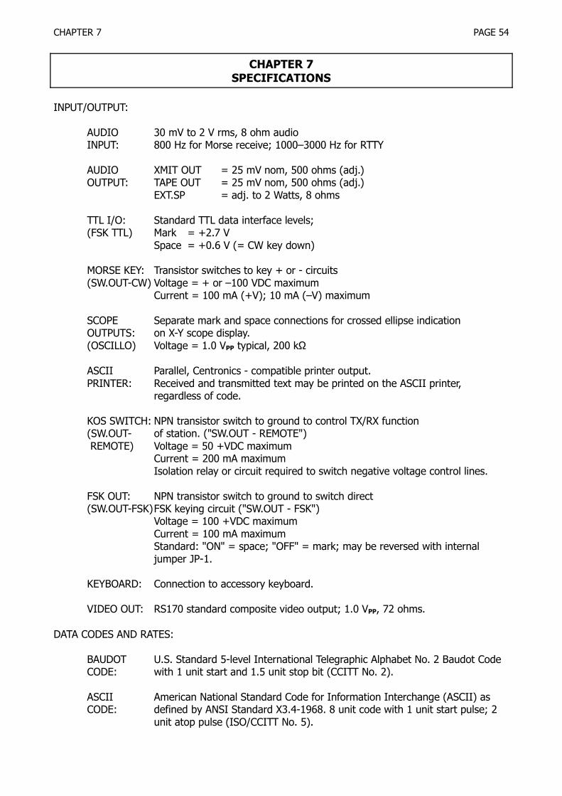
CHAPTER 7 PAGE 54
CHAPTER 7SPECIFICATIONS
INPUT/OUTPUT:
AUDIO 30 mV to 2 V rms, 8 ohm audioINPUT: 800 Hz for Morse receive; 1000–3000 Hz for RTTY
AUDIO XMIT OUT = 25 mV nom, 500 ohms (adj.)OUTPUT: TAPE OUT = 25 mV nom, 500 ohms (adj.)
EXT.SP = adj. to 2 Watts, 8 ohms
TTL I/O: Standard TTL data interface levels;(FSK TTL) Mark = +2.7 V
Space = +0.6 V (= CW key down)
MORSE KEY: Transistor switches to key + or - circuits(SW.OUT-CW) Voltage = + or –100 VDC maximum
Current = 100 mA (+V); 10 mA (–V) maximum
SCOPE Separate mark and space connections for crossed ellipse indicationOUTPUTS: on X-Y scope display.(OSCILLO) Voltage = 1.0 VPP typical, 200 kΩ
ASCII Parallel, Centronics - compatible printer output.PRINTER: Received and transmitted text may be printed on the ASCII printer,
regardless of code.
KOS SWITCH: NPN transistor switch to ground to control TX/RX function(SW.OUT- of station. ("SW.OUT - REMOTE") REMOTE) Voltage = 50 +VDC maximum
Current = 200 mA maximumIsolation relay or circuit required to switch negative voltage control lines.
FSK OUT: NPN transistor switch to ground to switch direct(SW.OUT-FSK)FSK keying circuit ("SW.OUT - FSK")
Voltage = 100 +VDC maximumCurrent = 100 mA maximumStandard: "ON" = space; "OFF" = mark; may be reversed with internaljumper JP-1.
KEYBOARD: Connection to accessory keyboard.
VIDEO OUT: RS170 standard composite video output; 1.0 VPP, 72 ohms.
DATA CODES AND RATES:
BAUDOT U.S. Standard 5-level International Telegraphic Alphabet No. 2 Baudot CodeCODE: with 1 unit start and 1.5 unit stop bit (CCITT No. 2).
ASCII American National Standard Code for Information Interchange (ASCII) asCODE: defined by ANSI Standard X3.4-1968. 8 unit code with 1 unit start pulse; 2
unit atop pulse (ISO/CCITT No. 5).

CHAPTER 7 PAGE 55
RTTY DATA Baudot or ASCII codes may be transmitted and received atRATES: 15.15, 50, 56.88, 74.2, 110, and 300 baud.
MORSE Continental Morse Code including all letters, numbers, period, comma, colon,CODE: dash, apostrophe, parentheses, quote, question mark, and AA, AR, AS, BT,
BT, KN, SK, and error prosigns. Receive speed automatically tracks from 1 to100 wpm speeds: transmit speed may be set for 4 to 33 wpm.
MODEMS:MORSE: AF Active filter or Phase-lock loop filter; 800 Hz nominal center frequency.
RTTY Mark = 2125 HzHIGH TONES: Space = 2295 Hz (170 Shift)
= 2550 Hz (425 Shift)= 2975 Hz (850 Shift)
CW ID a Space tone (all shifts)
RTTY Mark = 1275 Hz (170 Shift)LOW TONES: Space = 1445 Hz (170 Shift)
= 1700 Hz (425 Shift)= 2125 Hz (850 Shift)
CW ID = Spaoe tone (all shifts)
Transmit audio tone frequencies are automatically set to correspond to se-lected modem and shift; NORM/REV switch changes polarity of RX tones on-ly.
DISPLAY:
SCREEN: 5 inch diagonal measure (3.25" × 4.26") green CRT; 20 lines of 32 charac-ters per line; four pages may be selected for viewing.
PAGE 56 lines of 32 characters per line (4 pages); 25 lines of receive text, 15 linesMEMORY: of pretype transmit text; 12 lines of memory channel storage.
CHARACTERS: Full upper and lower case letters, all numbers and punctuation of the ASCIIcharacter set, special graphic symbols for ASCII control codes; 5×7 dot ma-trix; green characters on a dark background.
SCROLL: Received text is displayed on bottom line of receive area of screen; new textscrolls upward.
TX/RX CONTROL: Automatic Keyboard Operated Switch (KOS) or manual keyboard or manualfront panel switch control of station transmit-receive circuitry (+ voltage).
INDICATORS:
LED: Four LED indicators show MARK, SPACE, Morse center tuning (CW), andPower indicator.
SCREEN: One line of screen shows which CTRL- functions are presently in use; con-tents of all HERE IS messages are displayed on page 3. (See APPENDIX B)

CHAPTER 7 PAGE 56
SCOPE: Rear panel connections to vertical and horizontal amplifier inputs of an X-Yoscilloscope for conventional crossed-loop indication (Oscilloscope NOT in-cluded with CWR-6850).
KEYBOARD: 55 keys plus space bar, ASCII keyboard arrangement. RUB OUT allows back-up error correction.
MESSAGE STORAGE: Six, 64-character user-programmable HERE IS texts. CW ID may be included(HERE IS) within HERE IS 0 text.
FRONT PANEL CONTROLS:
SLIDE INPUT: Volume control for received signals.CONTROLS: VOLUME: Volume control to monitor CW sidetone and RTTY transmit
tones.SPEED: CW transmit speed adjustment.FINE: Fine tuning of RTTY space filter center frequency; detent for
optimum.
LEVER POWER CWR-6850 DC power switch.SWITCHES: SEND- SEND: The transceiver and CWR-6850 are set to transmit con-
AUTO- tinuouslyRECEIVE AUTO: The transceiver and CWR-6850 TX/RX condition may
be set by keyboard commands.RECEIVE: The transceiver and CWR-6850 are set to receive
continuously.
PUSH- RESET ON Erase receive screen, return cursor to initial receive position,BUTTON display 1st display page. Clear printer output register andSWITCHES erase memory transmission buffer.
FILTER ON Turns on CW PLL tracking filter; gives narrow bandwidth CWreceive response.
SPACE- Reduces CW reception interpretation time of word spacing byNARROW 25%.CWID A- CWID A: Transmit CW ID on SW-OUT CW, FSK, and 800CWID B Hz tone.
CWID B: Transmit CW ID using AFSK, mark-space RTTYtones.
DISPLAY PAGE: Cycle display pages on screen.MODE A: Page cycles between pages 0 and 1; used for
receive only.MODE B: Page cycles through all four pages; used for
TX/RX.CW - RTTY Selects between CW (Morse code) and RTTY (Baudot or
ASCII) codes.ASCII- Selects between the ASCII (8 unit) and BAUDOT (5 unit) RTTYBAUDOT codes.LTR ON Restores Baudot receive to LTRS case.FIG ON Restores Baudot receive to FIGS case.LOCK / In Baudot gives return to LTRS case after reception of a spaceUOS ON character. In ASCII locks receive and transmit characters to
upper case only.NOR - REV Reverses the sense of received signals - does not change
sense of transmitted tones.

CHAPTER 7 PAGE 57
BAUD Six interlocked switches set data rate for RTTY transmit andreceive to 45.45, 50.0, 56.9, 74.2, 110, 300 baud.
SHIFT Three interlocked switches set RTTY transmit and receive shiftto 170, 425 or 850 Hz.
TONE HIGH: Select RTTY "HIGH" tones for transmit and receive;mark = 2125 Hz.
LOW: Select RTTY "LOW" tones for transmit and receive;mark = 1275 Hz.
RX -TAPE RX: Audio signal connected to AF IN - RX jack is inter-preted by the CW and RTTY demodulators.
TAPE: Audio signal connected to AF IN - TAPE jack is interpreted by the CW and RTTY demodulators. Local"echo" of transmitted data is suppressed, giving fullduplex operation.
REAR PANEL KEY BOARD, PRINTER, VIDEO OUT, EXT SP, PHONE, TELEGRAPH KEY,CONNECTIONS: FSK TTL IN, FSK TTL OUT, AF OUT, SW OUT REMOTE, SW OUT FSK, SW
OUT CW, OSCILLO SPACE, OSCILLO MARK, AFSK OUT TX, AFSK OUT TAPE,AF IN TAPE, AF IN RX, FUSE, DC 13.8 V.
REAR PANEL FSK DEMOD: INT: Internal FSK demodulator used for reception of RTTY.CONTROLS: EXT: Internal FSK demodulator disconnected and received
data interpreted from the FSK TTL IN connector.AFSK GAIN: Controls output level to both AFSK OUT - TX and - TAPE con-
nectors.
BRIGHT: Controls contrast of internal screen.
MECHANICAL SPECIFICATIONS:
CWB6850: 12.7" W × 5.0" H × 12.5" D (13.25 × 5.1 × 11 clearance)32.26 cm × 12.7 cm × 31.75 cm (33.66 × 12.95 × 35.56 cm)Color: Dark gray top and bottom; black front panel; red, blue, gray, white
and black switch buttons. Green CRT phosphor.
KEYBOARD: 13.8" W × 2.3" H × 7.1" D35.05 cm × 5.84 cm × 18.03 cmColor: Light gray top; dark gray bottom; blue and gray keytops.
WEIGHTS: 16.5 lbs net, 20 lbs shipping (including keyboard)7.5 kg net, 9.1 kg shipping (including keyboard)
POWER 12 to 14.5 VDC (13.8 VDC nominal), 1.65 Amps. 22 Watts

APPENDIX A PAGE 58
APPENDIX ACWR-6850 KEYBOARD CONTROL COMMAND LIST
CONTROLKEY
STATUSINDICATOR
FUNCTION
CTRL-A
CTRL-C
CTRL-D
CTRL-E
CTRL-G
CTRL-I
CTRL-L:RETURN L
CTRL-N
CTRL-P
CTRL-Q:0CTRL-Q:1CTRL-Q:2CTRL-Q:3
CTRL-Q:other
CTRL-R:0CTRL-R:1CTRL-R:2CTRL-R:3CTRL-R:4CTRL-R:5
CTRL-R:other
CTRL-S:RETURN
CTRL-U
A
C
D
E
P
QQQQ
RRRRRR
S
U
ON - OFF control of automatic transmit-receive operation; SEND-AUTO-RECEIVE switch must be in AUTO position.
ON - OFF control of reception and transfer to the printer of ASCIIcontrol codes.
Extends CW transmit dash length by 25 %, reducing the effectiveCW "weight".
ON - OFF control of echo-back from transmit to receive buffer areas.
Inserts signal bell code in transmit buffer; effective only in ASCII andBaudot.
Changes transmit mode from RTTY to CW for all text to be transmit-ted. Shows reverse video star ( * ) in receive buffer.
Load start command to load contents of all six HERE IS memoriesfrom tape; control passes to tape and CWR-6850 will not respond tofurther keyboard commands until after an ASCII STX character is re-ceived from tape.
In Baudot, inserts FIG character in transmit buffer; in ASCII, insertsSI. No effect in CW.
ON - OFF control of the printer.
Set display to page 0Set display to page 1Set display to page 2Set display to page 3Set display to original display page.
Read contents of HERE IS 0 for transmissionRead contents of HERE IS 0 for transmissionRead contents of HERE IS 0 for transmissionRead contents of HERE IS 0 for transmissionRead contents of HERE IS 0 for transmissionRead contents of HERE IS 0 for transmissionRESET CTRL-R command
Transmit contents all 6 HERE IS messages to tape recorder for stor-age.
RTTY transmit speed is slowed to 25-baud equivalent speed by in-creasing the length of the stop pulse. The baud rate of the characteritself is not changed from that set by the BAUD switch.

APPENDIX A PAGE 59
CONTROLKEY
STATUSINDICATOR
FUNCTION
CTRL-W:0CTRL-W:1CTRL-W:2CTRL-W:3CTRL-W:4CTRL-W:5
CTRL-W:other
CTRL-X
CTRL-Y
CTRL-Z:BS
CTRL-Z:Shift-\
CTRL-Z:SHIFT-*
CTRL-^
CTRL-@
WWWWWW
X
Y
Z
Z
Z
^
Program HERE IS #0; end with RUB OUT key.Program HERE IS #1; end with RUB OUT key.Program HERE IS #2; end with RUB OUT key.Program HERE IS #3; end with RUB OUT key.Program HERE IS #4; end with RUB OUT key.Program HERE IS #5; end with RUB OUT key.Cancel ^W command.
Turn on transmitter and transmit data; works when SEND-AUTO-RECEIVE switch is in AUTO; transmitter stays on until second CTRL-Xis used to turn transmitter off.
ON - OFF control of word mode transmission.
Deletes final line in transmit buffer area; repeated BS operation dele-tes preceding line without further need of CTRL-Z.
Deletes all text in transmit buffer.
ON - OFF control of insertion of CW text in stream of otherwise RTTYin transmit buffer
Turns on sync-idle; stops sending transmit text until turned off with2nd CTRL-^.
Inserts NUL code in transmit buffer in ASCII; BLANK code in BAU-DOT. No effect in CW.

APPENDIX B PAGE 60
APPENDIX BCWR-6850 DISPLAY FORMAT
TOTAL DISPLAY CAPABILITY:

APPENDIX B PAGE 61
PAGE 0 and PAGE 1 DISPLAY FORMAT:

APPENDIX B PAGE 62
PAGE 2 and PAGE 3 DISPLAY FORMAT:

ADDENDUM PAGE 63
The following additions apply to your CWR-6850:
1. The command "CTRL-B" may be used to give a "break" transmit condition. The "break" com-mand in RTTY gives continuous SPACE condition output until a second CTRL-B is typed. The"break" command in CW gives continuous "key-down" condition until a second CTRL-B is typ-ed. The CTRL-B command may only be used when the SEND-AUTO-RECEIVE switch is in theSEND position. Activity of the "break" command is shown by the letter "B" in the status line.
2. The double vertical arrow symbol ( ) at the right-hand side of the status line is used to indi-cate that a command is waiting further input from the keyboard. Except for the ESC command,
commands showing ( ) can be canceled with the RUBOUT key. Also, the command will becanceled if a key other than the proper response is typed (for example any key except RETURNafter a CTRL-L). The exception is, of course, when CTRL-W is used to program the HERE ISmessages; only the RUBOUT ends HERE IS programming.
3. An open ( ) or closed ( ) right-arrow on the status line shows that data input from thekeyboard is not being accepted (such as during CTRL-L or CTRL-S operations). The arrowchanges from open ( ) to closed ( ) when the operation is active. Only the RESET frontpanel switch may be used to cancel the right-arrow commands.
4. The CTRL-Q:n command is used to change the display page from the keyboard as explained onpage 58 of the manual. When the CWR-6850 is first turned on, the display is set to displaypage 1 on the screen; other pages may be set with the CTRL-Q:0, CTRL-Q:2, etc. commands.CTRL-Q:5 will reset the display back to page 1. The CTRL-Q:5 return page may be set to anyother page with the following procedure: Use CTRL-Q:n to select the desired "default" displaypage and then type CTRL-Q:6. Now, the display will return to the new "default" page whenCTRL-Q:5 is used.
5. The following precautions apply when using the CWR-6850 with the ICOM brand of HF trans-ceivers (IC710, 720, 720A, 730):a. When using SW-OUT FSK connection (see section 5.3 of the manual) to drive the direct
FSK connection of the ICOM transceivers, it is necessary to invert the normal sense of theFSK output from mark = "on" to space = "on". To make this change, refer to section 6.4 ofthe manual and short-across jumper JP-1 on the digital board (top board). See Figure 10.for the location of JP-1. Refer to item (c) below for further considerations.
b. On the IC710 and IC720 (but NOT the IC720A), the FSK TTL OUT connection may be usedin place of the SW-OUT FSK connection for direct FSK, subject to conditions listed in (c)below.
c. Measure the voltage at the FSK input terminal to the ICOM transceiver:I. If a voltage larger than 5 volts is measured, use the SW-OUT FSK connection outlined instep (a) above.II. If no voltage is measured, use the FSK TTL OUT connection as discussed in step (b)above.
d. Do NOT use the audio signal on pin 4 of the ICOM accessory connector for audio outputconnection; connect the EXT-SP terminal of the ICOM to the AF IN RX connector of theCWR-6850 instead.
e. Use the REV position of the NOR-REV switch of the CWR-6850.f. When transmitting CW, place a solder short across JP-2 on the digital board (top board) as
explained in section 6.4 of the manual.g. If problems are experienced with transmit-receive control of the ICOM transceiver by the
CWR-6850, it may be necessary to change the value of R50 on the digital board. R50 is lo-cated at the center rear of the circuit board and is presently a 1500 ohm resistor. Becauseof the high current relays used in the ICOM transceivers, it may be necessary to replacethe 1500 ohm resistor with a 470 ohm resistor. This has not been found to a problem inour testing of the CWR-6850, but may be present on some units due to ICOM productionvariations between units.
6. The special considerations for the ICOM brand of HF transceivers does not seem to apply toother manufacturer's brands of transceivers with the possible exception of the choice of audio

ADDENDUM PAGE 64
output connection to the transceiver. ALWAYS use a low-impedance audio output such as theexternal speaker connection (or Kenwood phone patch output) rather than a high-impedance,low-level output (such as the TR7 auxiliary output).