telecommunications communications … used in this document to refer to either the entity claiming...
TRANSCRIPT

Telecommunications Communications Technologies
Basic Modems and Data Transmission (ASK / FSK / BPSK)
Courseware Sample 39864-F0

Order no.: 39864-10
First Edition
Revision level: 02/2015
By the staff of Festo Didactic
© Festo Didactic Ltée/Ltd, Quebec, Canada 2008
Internet: www.festo-didactic.com
e-mail: [email protected]
Printed in Canada
All rights reserved
ISBN 978-2-89640-262-5 (Printed version)
Legal Deposit – Bibliothèque et Archives nationales du Québec, 2008
Legal Deposit – Library and Archives Canada, 2008
The purchaser shall receive a single right of use which is non-exclusive, non-time-limited and limited
geographically to use at the purchaser's site/location as follows.
The purchaser shall be entitled to use the work to train his/her staff at the purchaser's site/location and
shall also be entitled to use parts of the copyright material as the basis for the production of his/her own
training documentation for the training of his/her staff at the purchaser's site/location with
acknowledgement of source and to make copies for this purpose. In the case of schools/technical
colleges, training centers, and universities, the right of use shall also include use by school and college
students and trainees at the purchaser's site/location for teaching purposes.
The right of use shall in all cases exclude the right to publish the copyright material or to make this
available for use on intranet, Internet and LMS platforms and databases such as Moodle, which allow
access by a wide variety of users, including those outside of the purchaser's site/location.
Entitlement to other rights relating to reproductions, copies, adaptations, translations, microfilming and
transfer to and storage and processing in electronic systems, no matter whether in whole or in part, shall
require the prior consent of Festo Didactic GmbH & Co. KG.
Information in this document is subject to change without notice and does not represent a commitment on
the part of Festo Didactic. The Festo materials described in this document are furnished under a license
agreement or a nondisclosure agreement.
Festo Didactic recognizes product names as trademarks or registered trademarks of their respective
holders.
All other trademarks are the property of their respective owners. Other trademarks and trade names may
be used in this document to refer to either the entity claiming the marks and names or their products.
Festo Didactic disclaims any proprietary interest in trademarks and trade names other than its own.

© Festo Didactic 39864-10 III
Safety and Common Symbols
The following safety and common symbols may be used in this manual and on the equipment:
Symbol Description
DANGER indicates a hazard with a high level of risk which, if not avoided, will result in death or serious injury.
WARNING indicates a hazard with a medium level of risk which, if not avoided, could result in death or serious injury.
CAUTION indicates a hazard with a low level of risk which, if not avoided, could result in minor or moderate injury.
CAUTION used without the Caution, risk of danger sign , indicates a hazard with a potentially hazardous situation which, if not avoided, may result in property damage.
Caution, risk of electric shock
Caution, hot surface
Caution, risk of danger
Caution, lifting hazard
Caution, hand entanglement hazard
Notice, non-ionizing radiation
Direct current
Alternating current
Both direct and alternating current
Three-phase alternating current
Earth (ground) terminal

Safety and Common Symbols
IV © Festo Didactic 39864-10
Symbol Description
Protective conductor terminal
Frame or chassis terminal
Equipotentiality
On (supply)
Off (supply)
Equipment protected throughout by double insulation or reinforced insulation
In position of a bi-stable push control
Out position of a bi-stable push control

© Festo Didactic 39864-10 V
Table of Contents
Preface .................................................................................................................. IX
Acknowledgements ............................................................................................... XI
About This Manual .............................................................................................. XIII
Conventions Used in This Manual ...................................................................... XV
List of Equipment Required ............................................................................... XVII
To the Instructor ................................................................................................. XIX
Unit 1 Baseband Data Transmission ...................................................... 1
DISCUSSION OF FUNDAMENTALS ......................................................... 1 Baseband data transmission ..................................................... 1 Pseudo-random binary sequences ............................................ 2
Ex. 1-1 Pseudo-Random Binary Sequences ............................................ 3
DISCUSSION ....................................................................................... 3 Test signals ............................................................................... 3 Characteristics of random data ................................................. 3 PRBS Characteristics ................................................................ 5
PROCEDURE ...................................................................................... 7 Set-up and connections ............................................................. 7 Time-domain observations ........................................................ 7 The power of PRBS signals ...................................................... 9 Frequency-domain observations ............................................. 11
Unit 2 Amplitude shift keying (ASK) ..................................................... 19
DISCUSSION OF FUNDAMENTALS ....................................................... 19 Disadvantages of baseband data transmission ...................... 19 Data transmission using modulation/demodulation ................. 20 Amplitude shift keying (ASK) ................................................... 20 Types of demodulation ............................................................ 21 Units of data transmission rate ................................................ 21 ASK performance .................................................................... 22
Ex. 2-1 Generation and Reception of ASK Signals ............................... 23
DISCUSSION ..................................................................................... 23 Generating ASK signals .......................................................... 23 The spectra of ASK signals ..................................................... 24 ASK signal demodulation ........................................................ 27
PROCEDURE .................................................................................... 27 Set-up and connections ........................................................... 27 Time-domain observations ...................................................... 28 Frequency-domain observations ............................................. 33

Table of Contents
VI © Festo Didactic 39864-10
Unit 3 Frequency shift keying (FSK) ..................................................... 43
DISCUSSION OF FUNDAMENTALS ....................................................... 43 Frequency shift keying (FSK) .................................................. 43 FSK communications standards .............................................. 44 FSK performance .................................................................... 47
Ex. 3-1 FSK Principles .............................................................................. 49
DISCUSSION ..................................................................................... 49 FSK modulation ....................................................................... 49 Time-domain characteristics of FSK signals ........................... 50 Frequency-domain characteristics of FSK signals .................. 51 FSK demodulation ................................................................... 53
PROCEDURE .................................................................................... 54 Set-up and connections ........................................................... 54 FSK modulation ....................................................................... 54 Frequency domain characteristics of FSK signals .................. 57 Effect of the ratio f /Rb ............................................................ 58 FSK demodulation ................................................................... 60
Ex. 3-2 Bell 202 Modem (1200 baud) ....................................................... 65
DISCUSSION ..................................................................................... 65 The Bell 202 and CCITT V.23 MODE 2 modem standards .... 65
PROCEDURE .................................................................................... 66 Set-up and connections ........................................................... 66 Bell 202 modem main channel FSK signal ............................. 67 Bell 202 modem back channel ASK signal ............................. 70 Back channel ASK demodulation ............................................ 74 4-wire transmission (optional) ................................................. 77
Unit 4 Binary Phase Shift Keying (BPSK) ............................................. 81
DISCUSSION OF FUNDAMENTALS ....................................................... 81 Comparison of ASK, FSK, and BPSK ..................................... 81 BPSK performance .................................................................. 82
Ex. 4-1 Generation and Demodulation of BPSK Signals ...................... 83
DISCUSSION ..................................................................................... 83 Binary phase shift keying ........................................................ 83 Generation of BPSK signals .................................................... 84 Time and frequency characteristics of BPSK signals .............. 84 Demodulation of BPSK signals ............................................... 85 The BPSK Demodulator .......................................................... 86 The phase-locked loop (PLL) .................................................. 88 The Costas loop mixer ............................................................ 90

Table of Contents
© Festo Didactic 39864-10 VII
PROCEDURE .................................................................................... 91 Set-up and connections ........................................................... 91 BPSK modulation .................................................................... 92 The BPSK spectrum ................................................................ 95 BPSK demodulation ................................................................ 97 The phase-locked loop circuit ................................................ 100 BPSK demodulation .............................................................. 105 The Costas loop .................................................................... 108
Unit 5 Troubleshooting Basic Modems .............................................. 113
DISCUSSION OF FUNDAMENTALS ..................................................... 113 Troubleshooting communications equipment ........................ 113 Troubleshooting activities ...................................................... 113
Ex. 5-1 Troubleshooting an ASK Communication System ................ 115
DISCUSSION ................................................................................... 115 Signal flow tracing ................................................................. 115 The divide-in-half method ...................................................... 116 A systematic troubleshooting procedure ............................... 116 Troubleshooting the ASK application .................................... 117
PROCEDURE .................................................................................. 117 Set-up and connections ......................................................... 117 Troubleshooting faults in an ASK communication system .... 118
Ex. 5-2 Troubleshooting an FSK Modem ............................................. 123
DISCUSSION ................................................................................... 123 Troubleshooting the FSK application .................................... 123
PROCEDURE .................................................................................. 123 Set-up and connections ......................................................... 123 Troubleshooting FSK modem faults ...................................... 124
Ex. 5-3 Troubleshooting a BPSK Communication System ................ 129
DISCUSSION ................................................................................... 129 Troubleshooting the BPSK application .................................. 129
PROCEDURE .................................................................................. 130 Set-up and connections ......................................................... 130 Troubleshooting faults in a BPSK communication system .... 131
Appendix A Glossary of New Terms ............................................................. 137
Index of New Terms ........................................................................................... 139
Acronyms ........................................................................................................... 141

Table of Contents
VIII © Festo Didactic 39864-10
Bibliography ....................................................................................................... 143

© Festo Didactic 39864-10 IX
Preface
Digital communication offers so many advantages over analog communication that the majority of today’s communications systems are digital.
Unlike analog communication systems, digital systems do not require accurate recovery of the transmitted waveform at the receiver end. Instead, the receiver periodically detects which waveform is being transmitted, among a limited number of possible waveforms, and maps the detected waveform back to the data it represents. This allows extremely low error rates, even when the signal has been corrupted by noise.
The digital circuits are often implemented using application specific integrated circuits (ASIC) and field-programmable gate arrays (FPGA). Although this “system-on-a-chip” approach is very effective for commercial and military applications, the resulting systems do not allow access to internal signals and data and are therefore poorly suited for educational use. It is for this reason that we designed the Communications Technologies Training System.
The Communications Technologies Training System, Model 8087, is a state-of-the-art communications training system. Specially designed for hands-on training, it facilitates the study of many different types of digital modulation/demodulation technologies such as PAM, PWM, PPM, PCM, Delta Modulation, ASK, FSK, and BPSK as well as spectrally efficient technologies such as QPSK, QAM, and ADSL. The system also enables the study of direct-sequence and frequency-hopping spread spectrum (DSSS and FHSS), two key technologies used in modern wireless communication systems (CDMA cellular-telephony networks, Global Positioning System, Bluetooth interface for wireless connectivity, etc.) to implement code-division multiple access (CDMA), improve interference rejection, minimize interference with other systems, etc. The system is designed to reflect the standards commonly used in modern communications systems.
Unlike conventional, hardware-based training systems that use a variety of physical modules to implement different technologies and instruments, the Communications Technologies Training System is based on a Reconfigurable Training Module (RTM) and the Communications Technologies (LVCT) software, providing tremendous flexibility at a reduced cost.
Each of the communications technologies to be studied is provided as an application that can be selected from a menu. Once loaded into the LVCT software, the selected application configures the RTM to implement the communications technology, and provides a specially designed user interface for the student.
The LVCT software provides settings for full user control over the operating parameters of each communications technology application. Functional block diagrams for the circuits involved are shown on screen. The digital or analog signals at various points in the circuits can be viewed and analyzed using the virtual instruments included in the software. In addition, some of these signals are made available at physical connectors on the RTM and can be displayed and measured using conventional instruments.
The courseware for the Communications Technologies Training System consists of a series of student manuals covering the different technologies as well as instructor guides that provide the answers to procedure step questions and to

Preface
X © Festo Didactic 39864-10
review questions. The Communications Technologies Training System and the accompanying courseware provide a complete study program for these key information-age technologies.
We invite readers of this manual to send us their tips, feedback, and suggestions for improving the book.
Please send these to [email protected].
The authors and Festo Didactic look forward to your comments.

© Festo Didactic 39864-10 XIII
About This Manual
Manual Objective
When you have completed this manual, you will be familiar with data transmission using three basic types of digital modulation: ASK, FSK and BPSK. You will be familiar with the modulation and demodulation techniques used, with the time and frequency domain characteristics of the modulated waveforms and with the advantages and disadvantages of each type of modulation. You will also have learned useful techniques for troubleshooting these modems.
Description
This Student Manual is divided into several units each of which covers one topic. Each unit begins with an Introduction presenting important background information. Following this are a number of exercises designed to present the subject matter in convenient instructional segments. In each exercise, principles and concepts are presented first followed by a step-by-step, hands-on procedure to complete the learning process.
Each exercise contains:
A clearly defined Exercise Objective
A Discussion Outline listing the main points presented in the Discussion
A Discussion of the theory involved
A Procedure Outline listing the main sections in the Procedure
A step-by-step Procedure in which the student observes and measures the important phenomena, including questions to help in understanding the important principles.
A Conclusion
Review Questions
a In this manual, all New Terms are defined in the Glossary of New Terms. In addition, an index of New Terms is provided at the end of this manual.
Safety considerations
Safety symbols that may be used in this manual and on the Lab-Volt equipment are listed in the Safety Symbols table at the beginning of the manual.
Safety procedures related to the tasks that you will be asked to perform are indicated in each exercise.
Make sure that you are wearing appropriate protective equipment when performing the tasks. You should never perform a task if you have any reason to think that a manipulation could be dangerous for you or your teammates.

About This Manual
XIV © Festo Didactic 39864-10
Systems of units
Units are expressed using the International System of Units (SI) followed by the units expressed in the U.S. customary system of units (between parentheses).

© Festo Didactic 39864-10 XIX
To the Instructor
You will find in this Instructor Guide all the elements included in the Student Manual together with the answers to all questions, results of measurements, graphs, explanations, suggestions, and, in some cases, instructions to help you guide the students through their learning process. All the information that applies to you is placed between markers and appears in red.
Accuracy of measurements
The numerical results of the hands-on exercises may differ from one student to another. For this reason, the results and answers given in this manual should be considered as a guide. Students who correctly performed the exercises should expect to demonstrate the principles involved and make observations and measurements similar to those given as answers.


Sample
Extracted from
Instructor Guide


© Festo Didactic 39864-10 115
When you have completed this exercise, you will be able to apply a systematic technique of signal flow tracing to diagnose instructor-inserted faults in the ASK application.
The Discussion of this exercise covers the following points:
Signal flow tracing The divide-in-half method A systematic troubleshooting procedure Troubleshooting the ASK application
Signal flow tracing
Signal flow tracing is the principal technique applied in troubleshooting, once a problem has been determined and enough information concerning the problem and its symptoms has been gathered. When performing troubleshooting exercises with the Communications Technologies Training System, it is important to refer to the System Diagram as well as to the block diagrams of each virtual module showing the locations of the test points. In addition, reviewing previous exercises can provide valuable information concerning system operation, and lead to more efficient troubleshooting.
The technique of signal flow tracing consists of analyzing signals at different points along their path. In some cases, an oscilloscope and a function generator are the only test equipment needed to troubleshoot digital communications equipment. In other cases, instruments such as a logic analyzer and a spectrum analyzer will be required.
The choice of which signal to analyze, and where to analyze it, should never be done on a random basis. A straight-forward, logical approach leads to quicker identification and correction of a problem. Knowing the operating principles of the equipment also reduces the time and effort required to diagnose a fault.
Signal flow tracing can be approached in two ways. They are basically the same except for the direction followed in analysis:
Signal flow tracing from input to output
Signal flow tracing from output to input
Depending on the ability and training of the troubleshooter, and the functional complexity of the equipment, one or the other of the two approaches will be preferred. Extensive knowledge of equipment operating principles is necessary to trace signals from output to input, while troubleshooting equipment with only one output and multiple inputs can often be better performed in this way.
Troubleshooting an ASK Communication System
Exercise 5-1
EXERCISE OBJECTIVE
DISCUSSION OUTLINE
DISCUSSION

Ex. 5-1 – Troubleshooting an ASK Communication System Discussion
116 © Festo Didactic 39864-10
In this manual, we suggest you perform signal flow tracing from input to output. We suggest this approach for the following reasons:
The approach is well adapted to the communications technologies presented in this manual.
It is the best method for students who have little experience in troubleshooting.
The divide-in-half method
A more rapid technique used by experienced personnel is the divide-in-half method. Basically, this method requires that the input and output of the equipment be checked to verify defective operation. Next, the complete circuit path is divided in half and signals near the center are checked to determine if the problem is in the first or the second half. Following this, the defective section is again divided in half to further locate the problem. This successive divide-in-half approach is applied until the last remaining functional block is checked and the fault located. Figure 5-1 illustrates the procedure for a problem located at functional block B. The dotted lines show where signals are checked and the circled numbers indicate the steps in sequential order.
Figure 5-1. The divide-in-half method of troubleshooting.
A systematic troubleshooting procedure
A systematic troubleshooting procedure is summarized in the following steps:
1. Observe the problem and note its symptoms. Using various tests, identify the module(s) or mode(s) which may be defective. If possible, perform a visual inspection for loose or damaged wires, connectors and components.
2. Check the power supplied to each suspected module and note all status LEDs and other indicators. In the Communications Technologies Training System, the RTM has a LED to indicate that power is supplied to the module, and each of the plug-in modules has a status (“OK”) LED that lights when the module is detected by the software.
A IN B C D E F G
1 1
OK
2
NOT OK
34
OK NOT OK
PROBLEM LOCATION
OUT
NOT OK

Ex. 5-1 – Troubleshooting an ASK Communication System Procedure Outline
© Festo Didactic 39864-10 117
3. Apply the appropriate signals and use signal flow tracing within the circuits suspected to be defective in order to locate a defective part of circuitry.
4. Verify if there are other branches of circuitry meeting at the point where defective operation was discovered. If so, verify that these branches are operating normally before concluding that the part of circuitry located in the previous steps is really defective.
5. Once a defective part of circuitry has been located, make sure that its malfunction plausibly explains the problem observed. If not, there may be another defective part of circuitry that contributes to the problem.
6. Diagnose the problem.
a This procedure is summarized on the Troubleshooting Worksheet at the end of each exercise.
Of the many different types of faults, the most difficult to identify are those that do not appear to prevent the system from working properly. This may be the case when a fault affects only certain controls or certain operating modes of a module, or when the problem is noticeable only under certain conditions. In these cases, familiarity with the nature of the signals and with the system's operation is essential. During the troubleshooting procedure, it is best to follow the signal flow from the system's input to output while varying the operation parameters.
Troubleshooting the ASK application
The ASK application is the simplest of the applications presented in this manual. Once you have identified the defective circuit (ASK Modulator or ASK Demodulator), signal flow tracing from output to input should allow you to rapidly locate the fault and diagnose the problem.
The Procedure is divided into the following sections:
Set-up and connections Troubleshooting faults in an ASK communication system
Set-up and connections
1. Turn on the RTM Power Supply and the RTM and make sure the RTM power LED is lit.
2. Start the LVCT software. In the Application Selection box, choose ASK and click OK. This begins a new session with all settings set to their default values and with all faults deactivated.
b If the software is already running, choose Exit in the File menu and restart LVCT to begin a new session with all faults deactivated.
PROCEDURE OUTLINE
PROCEDURE
File Restore Default Settings returns all settings to their default values, but does not deactivate activated faults.
Double-click to select SWapp
Ex. 5-1 – Troubleshooting an ASK Communication System Procedure
118 © Festo Didactic 39864-10
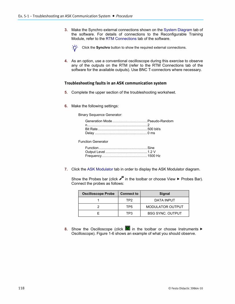
3. Make the Synchro external connections shown on the System Diagram tab of the software. For details of connections to the Reconfigurable Training Module, refer to the RTM Connections tab of the software.
b Click the Synchro button to show the required external connections.
4. As an option, use a conventional oscilloscope during this exercise to observe any of the outputs on the RTM (refer to the RTM Connections tab of the software for the available outputs). Use BNC T-connectors where necessary.
Troubleshooting faults in an ASK communication system
5. Complete the upper section of the troubleshooting worksheet.
6. Make the following settings:
Binary Sequence Generator:
Generation Mode .................................... Pseudo-Random n .............................................................. 2 Bit Rate ................................................... 500 bit/s Delay ...................................................... 0 ms
Function Generator
Function .................................................. Sine Output Level ........................................... 1.2 V Frequency ............................................... 1500 Hz
7. Click the ASK Modulator tab in order to display the ASK Modulator diagram.
Show the Probes bar (click in the toolbar or choose View Probes Bar). Connect the probes as follows:
Oscilloscope Probe Connect to Signal
1 TP2 DATA INPUT
2 TP5 MODULATOR OUTPUT
E TP3 BSG SYNC. OUTPUT
8. Show the Oscilloscope (click in the toolbar or choose Instruments Oscilloscope). Figure 1-6 shows an example of what you should observe.

Ex. 5-1 – Troubleshooting an ASK Communication System Conclusion
© Festo Didactic 39864-10 119
Figure 5-2. Data and ASK signals.
9. Observe the signal at each of the test points of the ASK Modulator and the ASK Demodulator. While doing this, vary the parameters of the input signals in order to become very familiar with the operation of the module.
10. Ask the instructor to activate a fault.
11. Carry out the Troubleshooting Procedure in order to locate the fault and diagnose the problem.
12. If desired, ask your instructor to activate another fault. Troubleshoot the new fault using a copy of the Troubleshooting Worksheet.
13. When you have finished using the system, exit the LVCT software and turn off the equipment.
In this exercise, you used a systematic, step-by-step troubleshooting method to locate a fault inserted in the ASK application.
This exercise has allowed you to acquire useful knowledge concerning troubleshooting, and you have been able to verify that a sound approach leads to quicker identification of the problem source. While you should not neglect any personal talents for troubleshooting that you may have discovered, it is important to combine these talents with the fundamental principles given in the exercise. This will reduce the chances of making errors when troubleshooting.
Oscilloscope Settings: Channel 1.................................. 5 V/div Channel 2.................................. 2 V/div Channel E ................................. 5 V/div Time Base .............................. 1 ms/div Trigger Slope ............................. Rising Trigger Level .................................. 2 V Trigger Source ................................ Ext
CONCLUSION
Data
ASK signal
Sync.

Ex. 5-1 – Troubleshooting an ASK Communication System Review Questions
120 © Festo Didactic 39864-10
1. Define troubleshooting.
Troubleshooting is the act of locating and diagnosing malfunctions or breakdowns in equipment by means of systematic checking or analysis.
2. What are two fundamental steps that should be used as a guide in any troubleshooting job?
The two fundamental steps are: first, observe the symptoms of the problem, and second, relate the problem to specific functional blocks.
3. What are the four levels of activity designed to identify, locate, and correct a problem? List them in the order in which they are performed during troubleshooting.
1. System level observations and tests
2. Signal flow tracing
3. Signal and component measurements
4. Module or component substitution and replacement
4. Why is signal flow tracing from output to input instead of from input to output a more difficult method to apply in troubleshooting?
It is a more difficult method to apply because extensive knowledge of equipment operating principles is necessary. Troubleshooting from output to input means that you must decide whether the output is correct based upon your theoretical knowledge and practical experience. This may be insufficient when working with unfamiliar equipment. When troubleshooting from input to output, you begin with a known signal and you check whether or not the following signals is a correctly transformed version of this known signal.
5. In certain cases, a fault may not appear to prevent a system from working properly. What approach should you take in this case?
In this case, it is best to follow the signal flow from the system’s input to its output while varying the operation parameters.
REVIEW QUESTIONS

Ex. 5-1 – Troubleshooting an ASK Communication System Troubleshooting Worksheet
© Festo Didactic 39864-10 121
TROUBLESHOOTING WORKSHEET
Student’s Name: ________________________________________________________________
Instructor’s Name: ________________________________________________________________
Fault:* ________________________________________________________________
Troubleshooting Procedure:
1. Identify the defective module(s) or mode(s) and check visually for damage.
2. Verify that power supplied to all modules. Note all status LEDs and other indicators.
3. Apply the appropriate signals and use signal flow tracing to locate the problem.
4. Verify any other input branch, if present.
5. Make sure the malfunction located plausibly explains the problem observed.
6. Diagnose the problem.
Problem Description and Symptoms: ________________________________________________________
______________________________________________________________________________________
______________________________________________________________________________________
______________________________________________________________________________________
______________________________________________________________________________________
Defective circuit: ________________________________________________________________________
______________________________________________________________________________________
Diagnosis: _____________________________________________________________________________
______________________________________________________________________________________
Instructor’s Comments: ___________________________________________________________________
______________________________________________________________________________________
Notes: ________________________________________________________________________________
______________________________________________________________________________________
______________________________________________________________________________________
* At instructor’s discretion


Unit 5 – Troubleshooting Basic Modems Unit Test
© Festo Didactic 39864-10 135
Unit Test
1. Troubleshooting communications equipment is basically the same as troubleshooting any other electrical, electronic, or mechanical device.
a. True. b. False.
a
2. Before troubleshooting any equipment the best way to start is to
a. check that the power is on. b. call the manufacturer of the equipment. c. read through the instruction manual to learn how the equipment
operates. d. check that the power is off.
c
3. To successfully perform troubleshooting it is necessary to
a. have had some experience operating the particular equipment. b. understand the equipment and its operation. c. talk to the equipment manufacturer. d. have the instruction manual of the equipment.
b
4. The two fundamental rules that serve as a guide for troubleshooting are
a. read the instruction manual and use your personal initiative. b. observe the symptoms of the problem and identify the specific functional
blocks related to the problem. c. learn how the system functions and substitute defective parts in the
system. d. none of the above.
b
5. Locating and diagnosing equipment malfunctions by systematic checking is known as
a. regular maintenance. b. equipment checking. c. equipment repair. d. troubleshooting.

Unit 5 – Troubleshooting Basic Modems Unit Test
136 © Festo Didactic 39864-10
d
6. Signal flow tracing is best performed using
a. a random basis approach. b. only the imagination of the troubleshooter. c. a straight-forward logical approach. d. the divide-in-half method.
c
7. Signal flow tracing from output to input
a. is exactly the same as signal flow tracing from input to output. b. is faster than the divide-by-half method. c. requires extensive knowledge of equipment operating principles. d. is a method used only to maintain communications equipment.
c
8. The divide-in-half technique of troubleshooting
a. is well adapted for use by inexperienced personnel. b. is unsuitable for troubleshooting communications equipment. c. is rapid, but requires good knowledge of the equipment. d. requires much more time than other methods.
c
9. One of the first things to verify when troubleshooting is
a. the equipment's power input. b. the electric company's line voltage. c. the frequency of the ac power circuit. d. none of the above.
a
10. A fault may not appear to prevent a system from working properly. In this case, you
a. use the divide in half method to troubleshoot the system. b. follow the signal flow from the system's input to its output while varying
the operation parameters. c. let the equipment warm up and take a coffee break. d. call your instructor and ask him to insert a fault in your system.
b

© Festo Didactic 39864-10 143
Bibliography
HAYKIN, Simon, Communication Systems, New York, John Wiley & Sons, 1978. ISBN 0-471-02977-7
SHANMUGAN, K. Sam, Digital and Analog Communication Systems, New York, John Wiley & Sons, 1979. ISBN 0-471-03090-2
SINNEMA, William, Digital, Analog, and Data Communication Systems, Second Edition, Englewood Cliffs, New Jersey, Prentice-Hall, 1986. ISBN 0-8359-1301-5
SMITH, David R., Digital Transmission Systems, New York, Van Nostrand Reinhold, 1985 ISBN 0-534-03382-2
STREMLER, Ferrel G., Introduction to Communication Systems, Second Edition, Reading, Massachusetts, Addison-Wesley, 1982. ISBN 0-201-07251-3
