techsheet rs232 to ttl converter
TRANSCRIPT
7/27/2019 TechSheet RS232 to TTL Converter
http://slidepdf.com/reader/full/techsheet-rs232-to-ttl-converter 1/3
R101-0513+ADAP
www.procerusuav.com 801-224-5713 02/14/08
Kest rel TTL to RS-232 Con vert er
FEATURES
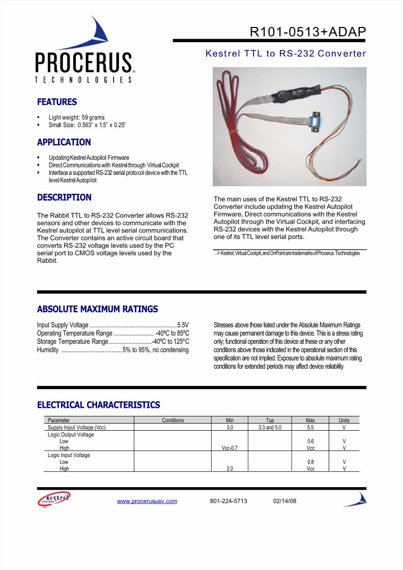
Light weight: 59 grams Small Size: 0.563” x 1.5” x 0.25”
APPLICATION
Updating Kestrel Autopilot Firmware Direct Communications with Kestrel through Virtual Cockpit Interface a supported RS-232 serial protocol device with the TTL
level Kestrel Autopilot
DESCRIPTION
The Rabbit TTL to RS-232 Converter allows RS-232sensors and other devices to communicate with theKestrel autopilot at TTL level serial communications.The Converter contains an active circuit board thatconverts RS-232 voltage levels used by the PCserial port to CMOS voltage levels used by theRabbit.
The main uses of the Kestrel TTL to RS-232Converter include updating the Kestrel AutopilotFirmware, Direct communications with the Kestrel
Autopilot through the Virtual Cockpit, and interfacingRS-232 devices with the Kestrel Autopilot throughone of its TTL level serial ports.
Kestrel, Virtual Cockpit, and OnPoint are trademarks of Procerus Technologies
ABSOLUTE MAXIMUM RATINGS
Input Supply Voltage ........................................................... 5.5VOperating Temperature Range ........................... -40ºC to 85ºCStorage Temperature Range ............................. -40ºC to 125ºCHumidity ......................................... 5% to 95%, no condensing
Stresses above those listed under the Absolute Maximum Ratingsmay cause permanent damage to this device. This is a stress ratingonly; functional operation of this device at these or any other conditions above those indicated in the operational section of thisspecification are not implied. Exposure to absolute maximum ratingconditions for extended periods may affect device reliability
ELECTRICAL CHARACTERISTICS
Parameter Conditions Min Typ Max Units
Supply Input Voltage (Vcc) 3.0 3.3 and 5.0 5.5 V
Logic Output VoltageLowHigh Vcc-0.7
0.6Vcc
VV
Logic Input VoltageLowHigh 2.0
0.8Vcc
VV

7/27/2019 TechSheet RS232 to TTL Converter
http://slidepdf.com/reader/full/techsheet-rs232-to-ttl-converter 2/3
R101-0513+ADAP
2 www.procerusuav .com 801-224-5713 02/14/08
PHYSICAL CHARACTERISTICS
Parameter Conditions Typ Units
Dimensions 0.563” x 1.5” x 0.25” Inches
Weight 59 Grams
RELATED PARTS
The following table contains parts that may be used with the Servo Expansion Board. These parts can be purchased from ProcerusTechnologies or distributors like Digikey or Mouser.
Part Number Manufacturer Description Comments
MOLEX5POS-L12 Procerus Technologies 5 PIN 1.25MM 12” WIRE PIGTAIL CONNECTOR 5 pin pigtails for Kestrel autopilot serial (Port E)
50058-8000 Molex/Walden CONN TERM FEMALE 28-32AWG TIN Crimp Terminal (Used For Hand Crimping)
51021-0500 Molex/Walden CONN HOUSING 5POS 1.25MM 5 Pin Connector Housing (Used For Hand Crimping)
TYPICAL APPLICATION
Kestrel Firmware Updates
The Converter can be used to update Kestrel firmware by plugging the 5-pin Kestrel connector into port A of theKestrel Autopilot. This results in pulling the Rabbit 2000 SMODE lines high, and causes the Rabbit to enter coldboot mode after a reset. The reset occurs when the RFU opens the serial port of the PC with the DTR line high,and then changes it to low. This pulses the reset line on the RabbitLink. In cold boot mode the processor runs asmall program contained in an internal ROM. This program receives triplets sent by the PC. It is through thismechanism that the RFU sends firmware to the RabbitLink.
Direct Kestrel-Virtual Cockpi t Communications
The Converter can be used to facilitate direct communications, between a Kestrel Autopilot and the VirtualCockpit software, thus bypassing wireless modem communications. This is achieved by plugging the 5-pin
Kestrel connector into the Modem port of the Autopilot, and connecting the DB9 connector into the serial port of your computer or into a USB to RS-232 adapter connected to a PC. Next, power-up the Kestrel Autopilot and therun the Virtual Cockpit application. Then from the Virtual Cockpit, select the correct Com port and open theconnection. Commands can then be sent to Autopilot directly through the Kestrel TTL to RS-232 Converter cable.
Interface RS-232 Serial Device with Kestrel TTL Serial Ports
The Converter can be used to connect supported devices to the Kestrel Autopilot that communicate using RS-232serial communications to a Kestrel Autopilot TTL level serial port.

7/27/2019 TechSheet RS232 to TTL Converter
http://slidepdf.com/reader/full/techsheet-rs232-to-ttl-converter 3/3
R101-0513+ADAP
3 www.procerusuav .com 801-224-5713 02/14/08
PORT DESCRIPTIONS
This section describes ports or pin out on the Kestrel TTL toRS-232 Converter. The pinout for DB9 Connector associatedwith the RS-232 side of the Converter Board is shown inFigure 1. The pinout for the Kestrel autopilot connector isshown in Figure 2 and the pinout for the converter board isshown in Figure 3.
Ground: Power common ground. This pin connects to allgrounds on this device.
Figure 2 Kestrel 5-pin Connector Pinout
VIN: Converter power. Connect this pin to +5 or +3.3 Voltsfrom autopilot. This pin powers the onboard IC.
Figure 1 RS-232 DB9 Connector Pinout
Figure 3 Converter Board Pinout
TTL (Autopilot)1. Autopilot Rx2. Ground3. Clock4. VIN (3V-5V)5. Autopilot Reset6. Autopilot Tx7. Not Connected8. Status9. SMode 010. SMode 1
1 6
2 7
3 8
4 9
5 NC
1 2
3 4
5 6
7 8
9 10
Autopilot Reset (PC DTR)
Autopilot Rx (PC Tx)
Autopilot Tx (PC Rx)
Power
Ground
5 4 3 2 1
9 8 7 6