technical specification for polemounting distribution transformers · 2015-08-06 · technical...
TRANSCRIPT

. Specification JTS02-01-01 Ver 9
Ergon Energy Corporation Limited ABN 50 087 646 062
Joint Ergon Energy/Energex
Technical Specification for Polemounting Distribution
Transformers
JTS02-01-01

Technical Specification for Polemounting Distribution Transformers
i Specification JTS02-01-01 Ver 9
Ergon Energy Corporation Limited ABN 50 087 646 062
Contents 1. Purpose and Scope...................................................................................................... 1
2. References.................................................................................................................... 1
2.1 Applicable Standards .......................................................................................... 1
2.2 Applicable Laws .................................................................................................. 1
3. Options per Attachment "C" of the Energy Networks Association (ENA) Doc 007 Specification ....................................................................................................................... 2
3.1 The Purchaser will require option 4. Details for this option must be included in the tender for all items.................................................................................................... 2
4. Variations from the ENA Doc 007 Specification........................................................ 2
4.1 Minimum Power Efficiency (MEPS) .................................................................... 2
4.2 Rating/Terminal Marking Plate............................................................................ 2
4.3 Insulating Oil ....................................................................................................... 2
4.4 Deletion of ENA Doc 007 Clause 5.15 comparison of tenders............................ 3
4.5 Transformer Losses ............................................................................................ 3
4.6 Drawings............................................................................................................. 3
4.7 Extra Holes in Mounting Bracket......................................................................... 4
4.8 Schedules of Attachment 2 ................................................................................. 4
4.9 Factory Acceptance Testing - Item and Sub-system Functional Testing .......... 13
4.10 Tappings ........................................................................................................... 13
5. Corrections and or clarifications to the ENA Doc 007 Specification..................... 14
5.1 Attachment 1 Specific Requirements ................................................................ 14
5.2 Attachment ‘A’ - Specific Requirements............................................................ 14
6. Additional Items ......................................................................................................... 14
The following additional items must be added to the ENA Doc 007 specification. .... 14
7. Additional Requirements........................................................................................... 17
7.1 Additional Requirement 1 - Low-voltage Current Transformers (CTs) and capability requirements to enable Distribution Transformer future-fitted Low-voltage (LV) Monitoring ............................................................................................................ 17
7.2 Additional Requirement 2 - HV and LV Surge Arrester and ancillary equipment17

Technical Specification for Polemounting Distribution Transformers
ii Specification JTS02-01-01 Ver 9
Ergon Energy Corporation Limited ABN 50 087 646 062
8. Attachment 1 – Additional Requirements ................................................................ 19
9. Attachment 2 – Risk Assessment............................................................................. 20
10. Attachment 3 – Transformer Name Plate Details .................................................... 22

Technical Specification for Polemounting Distribution Transformers
Page 1 of 22 Specification JTS02-01-01 Ver 9
Ergon Energy Corporation Limited ABN 50 087 646 062
1. Purpose and Scope
This technical specification is based on the Energy Networks Association (ENA) Doc 007: Specification for polemounting distribution transformers. Except for the variations listed below in clause 3, all transformers will fully comply with the ENA Doc 007 specification. Items 1 to 51 as numbered and described in ENA Doc 007 shall be deemed the technical specification Items 1 to 51 of JTS 02-01-01. Extra pole transformer technical specification items 52 to 60 are as nominated in Clause 5 of JTS 02-01-01.
2. References
2.1 Applicable Standards Unless specified otherwise, all equipment must comply with the latest current version of all relevant Queensland Safety Acts/Regulations and Australian/International Standards, (and where directly relevant to the equipment in it’s own right, and any considerations of normal Energy Industry Sector application) the National Electricity Law, National Electricity Regulations, and National Electricity Rules, including all parts and amendments. The following documents must be read in conjunction with this specification: • ENA Doc 007 specification for ‘Polemounting Distribution Transformers’ • TS-481 LV Transformer Monitoring Capability Requirements for Pole Top and Ground
Type Transformers N.B. TS-481 specification requirements include system component parts including the CTs to the junction box and associated internal and external junction box parts, flexible umbilical cable(s), and plug sockets and plug socket environmental protection/dust caps.
• TS449 Gapless Metal-Oxide Surge Arresters and TS449 General Requirements • ENERGEX drawing 4920-A4 Sect 7 Page 1 • ENERGEX drawing 4920-A4 Sect 7 Page 54 • ENERGEX drawing 141-A4 as typical for information • ERGON drawing 891709-01 LV Arrester Connection Detail (50 kVA Single
Phase/SWER) • ERGON drawing 891717-01 LV Arrester Connection Detail (25 - 500 kVA Three Phase) • ERGON drawing 891718-01 LV Arrester Connection Detail (10 - 25 kVA Single
Phase/SWER) • ERGON drawing FILE: 5 01 1138 1 Page 61 E Note: ENA Doc007 (as published by Standards Australia, GPO Box 476, Sydney, NSW 2001 for the Energy Networks Association, Level 3, 40 Blackall Street, Barton, ACT 2600) may be available from Energy Networks Australia and or it's nominated distributors of technical information, for example SAI Global Limited (a public company wholly owned by Standards Australia International Limited ('Standards Australia')) http://www.saiglobal.com.
2.2 Applicable Laws The Tenderer warrants (without limiting any other warranties or conditions implied by law) that all Goods have been produced, sold and delivered to the Principal in compliance with all applicable laws (including all workplace health and safety and electrical safety legislation, codes of conduct and the Principal’s Workplace Health & Safety and Electrical Safety Conditions)

Technical Specification for Polemounting Distribution Transformers
Page 2 of 22 Specification JTS02-01-01 Ver 9
Ergon Energy Corporation Limited ABN 50 087 646 062
3. Options per Attachment "C" of the Energy Networks Association (ENA) Doc 007 Specification
3.1 The Purchaser will require option 4. Details for this option must be included in the tender for all items.
4. Variations from the ENA Doc 007 Specification
In addition to the basic ENA Doc 007 specification the Purchaser has some specific requirements. The following variations therefore apply.
4.1 Minimum Power Efficiency (MEPS) All transformers must meet or exceed the minimum power efficiency levels specified in Table 1 of AS 2374.1.2 - 2003 Minimum Energy Performance Standard (MEPS). Transformers with efficiencies not meeting or improving performance upon these MEPS levels are unacceptable. During the term of the Contract, the Purchaser reserves the right to negotiate with the Supplier to enhance the transformer power efficiency levels to meet any future amendments to the MEPS requirement of AS2374.1.2.
4.2 Rating/Terminal Marking Plate In addition to the ENA Doc 007 specification requirements, the rating plate will include a statement of compliance with AS 2374.1.2. Any special performance attributes must be marked on the transformer; e.g. stencil "<Special Insulating Oil "Type">" on wall of tank above kV.A rating using black paint, 75 {mm} high and width not less than 12 {mm} - requirements subject to confirmation by the Purchaser. These agreed details will also be included on the Rating and Designation Plates.
4.3 Insulating Oil In addition and variation, where applicable to ENA Doc 007 Clause 5.6 Cooling and ENA Doc 007 SubClause 5.6.2 and ENA Doc 007 Clause 5.7 Drying out and oil filling before delivery, the Purchaser requires that any insulating oil offered complies with: AS 1767, and be proven to be non-corrosive by Method B of ASTM D1275-06 Standard Test Method for Corrosive Sulphur in Electrical Insulating Oils and, IEC 62535 Ed. 1.0: Insulating liquids – Test method for detection of potentially corrosive sulphur in used and unused insulating oil. Any and each oil offered will be certified as polychlorinated biphenyl-free (PCB-free) in accordance with the definition of PCB-free in the Environmental Protection (Waste Management) Regulations 2000 (Qld). Analysis shall be conducted in a laboratory certified by NATA for the appropriate analyses. The Tenderer will supply full specifications and test results for any and each oil offered. The quality of any offered insulating oil at the time of filling (i.e. on release from supplier) is such as to have a moisture content of at least < 20 ppm and a Breakdown Voltage of ≥ 50 kV.

Technical Specification for Polemounting Distribution Transformers
Page 3 of 22 Specification JTS02-01-01 Ver 9
Ergon Energy Corporation Limited ABN 50 087 646 062
4.4 Deletion of ENA Doc 007 Clause 5.15 comparison of tenders The Purchaser advises that ENA Doc 007 Clause 5.15 is deleted. Please refer the following clause 3.5.
4.5 Transformer Losses 4.5.1 Guaranteed load and no-load loss figures are to be specified in Attachment 1.
4.5.2 Load losses are to be corrected to a reference temperature of 75°C.
4.5.3 Guaranteed Losses
In evaluating the tenders, the Purchaser will capitalise the guaranteed losses and so determine the economic advantages of the transformers offered. Capitalisation of losses will be based on the guaranteed losses at the required power rating for each item as stated in Attachment 1. Load losses will be those specified on the principal tapping. For this contract, the following values will be used for the purpose of making a fair economic comparison:
TRANSFORMER RATING
F (NO-LOAD LOSS)/ kW
C (LOAD LOSS)/ kW
Up to and including 63 kV.A
$6300 $700
100 kV.A and above
$6300 $1800
F and C are the $/kW capitalisation figures for the no-load and load losses respectively.
4.5.4 Allowable tolerance As specified in AS 60076.1, the maximum allowable tolerance for the total losses for all transformers to be supplied under this contract is +10%. For any transformer, the maximum allowable tolerance for either the no-load loss or load loss is +15%, provided that the total loss meets the above requirement of +10%. Where the total loss exceeds the +10 % tolerance or either the no-load loss or load loss exceeds the +15 % tolerance, the Purchaser reserves the right to reject the unit. As an alternative, the unit may be accepted with the application of Liquidated Damages as described in the Liquidated Damages portion of the Standing Order.
4.6 Drawings The following clause replaces clause 8.1.2 of the ENA Doc 007 specification. The Supplier must exercise reasonable diligence in the design of Items in order to satisfy any Purchaser specific integration requirements between the Supplier's offered item and the Purchaser’s requirements for the item to be utilised in the Purchaser’s Power Supply Network. The Purchaser will comment on drawings supplied under this contract in relation to how the equipment interfaces with the Purchaser's design, construction, operation, maintenance and other requirements. Comments about drawings by the Purchaser shall not in any way absolve the Supplier of responsibility for the safety and reliability aspects of the plant or equipment supplied. The Supplier will amend the drawings as directed and resubmit them to the Purchaser within one week.
Technical Specification for Polemounting Distribution Transformers
Page 4 of 22 Specification JTS02-01-01 Ver 9
Ergon Energy Corporation Limited ABN 50 087 646 062
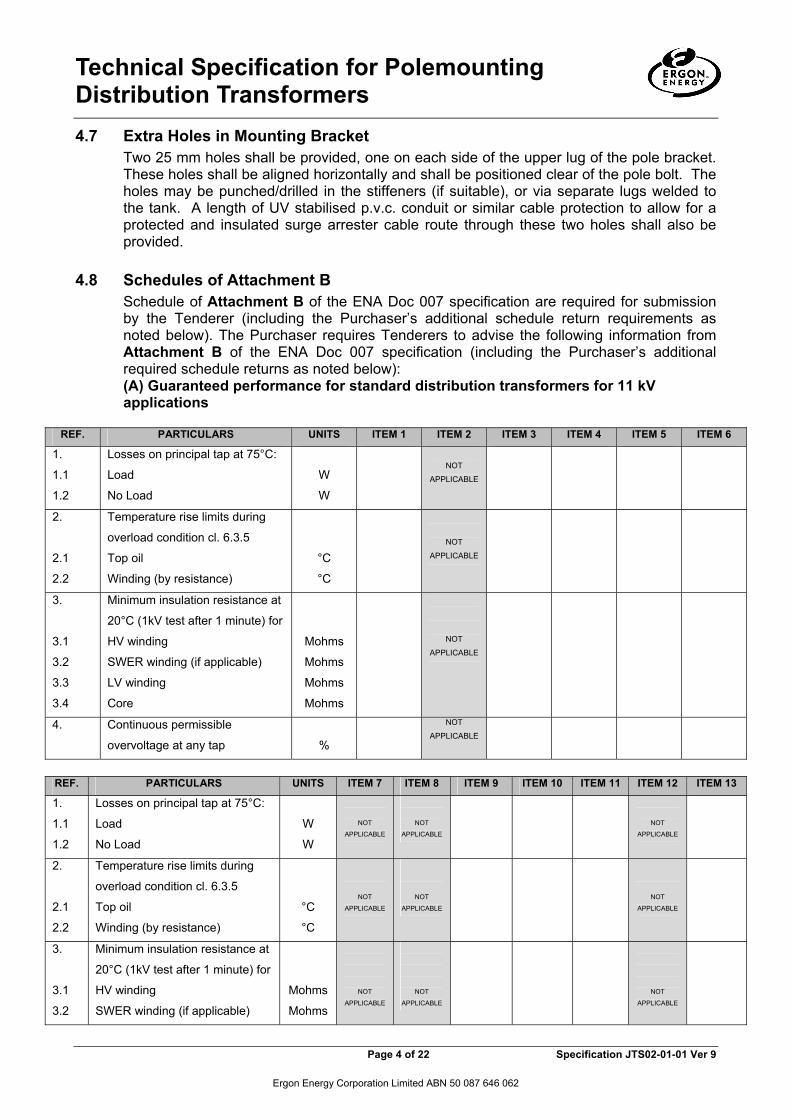
4.7 Extra Holes in Mounting Bracket Two 25 mm holes shall be provided, one on each side of the upper lug of the pole bracket. These holes shall be aligned horizontally and shall be positioned clear of the pole bolt. The holes may be punched/drilled in the stiffeners (if suitable), or via separate lugs welded to the tank. A length of UV stabilised p.v.c. conduit or similar cable protection to allow for a protected and insulated surge arrester cable route through these two holes shall also be provided.
4.8 Schedules of Attachment B
Schedule of Attachment B of the ENA Doc 007 specification are required for submission by the Tenderer (including the Purchaser’s additional schedule return requirements as noted below). The Purchaser requires Tenderers to advise the following information from Attachment B of the ENA Doc 007 specification (including the Purchaser’s additional required schedule returns as noted below): (A) Guaranteed performance for standard distribution transformers for 11 kV applications
REF. PARTICULARS UNITS ITEM 1 ITEM 2 ITEM 3 ITEM 4 ITEM 5 ITEM 6
1.
1.1
1.2
Losses on principal tap at 75°C:
Load
No Load
W
W
NOT
APPLICABLE
2.
2.1
2.2
Temperature rise limits during
overload condition cl. 6.3.5
Top oil
Winding (by resistance)
°C
°C
NOT
APPLICABLE
3.
3.1
3.2
3.3
3.4
Minimum insulation resistance at
20°C (1kV test after 1 minute) for
HV winding
SWER winding (if applicable)
LV winding
Core
Mohms
Mohms
Mohms
Mohms
NOT
APPLICABLE
4. Continuous permissible
overvoltage at any tap
%
NOT
APPLICABLE
REF. PARTICULARS UNITS ITEM 7 ITEM 8 ITEM 9 ITEM 10 ITEM 11 ITEM 12 ITEM 13
1.
1.1
1.2
Losses on principal tap at 75°C:
Load
No Load
W
W
NOT
APPLICABLE
NOT
APPLICABLE
NOT
APPLICABLE
2.
2.1
2.2
Temperature rise limits during
overload condition cl. 6.3.5
Top oil
Winding (by resistance)
°C
°C
NOT
APPLICABLE
NOT
APPLICABLE
NOT
APPLICABLE
3.
3.1
3.2
Minimum insulation resistance at
20°C (1kV test after 1 minute) for
HV winding
SWER winding (if applicable)
Mohms
Mohms
NOT
APPLICABLE
NOT
APPLICABLE
NOT
APPLICABLE

Technical Specification for Polemounting Distribution Transformers
Page 5 of 22 Specification JTS02-01-01 Ver 9
Ergon Energy Corporation Limited ABN 50 087 646 062
3.3
3.4
LV winding
Core
Mohms
Mohms
4. Continuous permissible
overvoltage at any tap
%
NOT
APPLICABLE
NOT
APPLICABLE
NOT
APPLICABLE
(A) Guaranteed performance for standard distribution transformers for 22 kV applications
REF. PARTICULARS UNITS ITEM 15
1.
1.1
1.2
Losses on principal tap at 75°C:
Load
No Load
W
W
NOT
APPLICABLE
2.
2.1
2.2
Temperature rise limits during
overload condition cl. 6.3.5
Top oil
Winding (by resistance)
°C
°C
NOT
APPLICABLE
3.
3.1
3.2
3.3
3.4
Minimum insulation resistance at
20°C (1kV test after 1 minute) for
HV winding
SWER winding (if applicable)
LV winding
Core
Mohms
Mohms
Mohms
Mohms
NOT
APPLICABLE
4. Continuous permissible
overvoltage at any tap
%
NOT
APPLICABLE
REF. PARTICULARS UNITS ITEM 20 ITEM 21 ITEM 23 ITEM 24 ITEM 25 ITEM 26
1.
1.1
1.2
Losses on principal tap at 75°C:
Load
No Load
W
W
NOT
APPLICABLE
NOT
APPLICABLE
NOT
APPLICABLE
2.
2.1
2.2
Temperature rise limits during
overload condition cl. 6.3.5
Top oil
Winding (by resistance)
°C
°C
NOT
APPLICABLE
NOT
APPLICABLE
NOT
APPLICABLE
3.
3.1
3.2
3.3
3.4
Minimum insulation resistance at
20°C (1kV test after 1 minute) for
HV winding
SWER winding (if applicable)
LV winding
Core
Mohms
Mohms
Mohms
Mohms
NOT
APPLICABLE
NOT
APPLICABLE
NOT
APPLICABLE
4. Continuous permissible
overvoltage at any tap
%
NOT
APPLICABLE
NOT
APPLICABLE
NOT
APPLICABLE

Technical Specification for Polemounting Distribution Transformers
Page 6 of 22 Specification JTS02-01-01 Ver 9
Ergon Energy Corporation Limited ABN 50 087 646 062
(A) Guaranteed performance for standard distribution transformers for 33 kV applications
REF. PARTICULARS UNITS ITEM 27 ITEM 28 ITEM 29 ITEM 30 ITEM 31
1.
1.1
1.2
Losses on principal tap at 75°C:
Load
No Load
W
W
NOT
APPLICABLE
2.
2.1
2.2
Temperature rise limits during
overload condition cl. 6.3.5
Top oil
Winding (by resistance)
°C
°C
NOT
APPLICABLE
3.
3.1
3.2
3.3
3.4
Minimum insulation resistance at
20°C (1kV test after 1 minute) for
HV winding
SWER winding (if applicable)
LV winding
Core
Mohms
Mohms
Mohms
Mohms
NOT
APPLICABLE
4. Continuous permissible
overvoltage at any tap
%
NOT
APPLICABLE
REF. PARTICULARS UNITS ITEM 32 ITEM 33 ITEM 34 ITEM 35
1.
1.1
1.2
Losses on principal tap at 75°C:
Load
No Load
W
W
2.
2.1
2.2
Temperature rise limits during
overload condition cl. 6.3.5
Top oil
Winding (by resistance)
°C
°C
3.
3.1
3.2
3.3
3.4
Minimum insulation resistance at
20°C (1kV test after 1 minute) for
HV winding
SWER winding (if applicable)
LV winding
Core
Mohms
Mohms
Mohms
Mohms
4. Continuous permissible
overvoltage at any tap
%

Technical Specification for Polemounting Distribution Transformers
Page 7 of 22 Specification JTS02-01-01 Ver 9
Ergon Energy Corporation Limited ABN 50 087 646 062
(A) Guaranteed performance for SWER isolating transformers
REF. PARTICULARS UNITS ITEM 36 ITEM 37 ITEM 38 ITEM 39
1.
1.1
1.2
Losses on principal tap at 75°C:
Load
No Load
W
W
2.
2.1
2.2
Temperature rise limits during
overload condition cl. 6.3.5
Top oil
Winding (by resistance)
°C
°C
3.
3.1
3.2
3.3
3.4
Minimum insulation resistance at
20°C (1kV test after 1 minute) for
HV winding
SWER winding (if applicable)
LV winding
Core
Mohms
Mohms
Mohms
Mohms
4. Continuous permissible
overvoltage at any tap
%
REF. PARTICULARS UNITS ITEM 40 ITEM 41 ITEM 42 ITEM 43
1.
1.1
1.2
Losses on principal tap at 75°C:
Load
No Load
W
W
2.
2.1
2.2
Temperature rise limits during
overload condition cl. 6.3.5
Top oil
Winding (by resistance)
°C
°C
3.
3.1
3.2
3.3
3.4
Minimum insulation resistance at
20°C (1kV test after 1 minute) for
HV winding
SWER winding (if applicable)
LV winding
Core
Mohms
Mohms
Mohms
Mohms
4. Continuous permissible
overvoltage at any tap
%

Technical Specification for Polemounting Distribution Transformers
Page 8 of 22 Specification JTS02-01-01 Ver 9
Ergon Energy Corporation Limited ABN 50 087 646 062
Guaranteed Performance for SWER Distribution Transformers
REF. PARTICULARS UNITS
1.
1.1
1.2
Losses on principal tap at 75°C:
Load
No Load
W
W
2.
2.1
2.2
Temperature rise limits during
overload condition cl. 6.3.5
Top oil
Winding (by resistance)
°C
°C
3.
3.1
3.2
3.3
3.4
Minimum insulation resistance at
20°C (1kV test after 1 minute) for
HV winding
SWER winding (if applicable)
LV winding
Core
Mohms
Mohms
Mohms
Mohms
4. Continuous permissible
overvoltage at any tap
%
(A) Guaranteed Performance for All Items
REF. PARTICULARS UNITS ITEMS 1 TO 60 (N.B. Items Groups C and H NOT awarded)
1.
Non-compliance:
Does the offered equipment fully comply with this specification?
Yes/No
2.
2.1
2.2
2.3
Insulating oil:
Type
Does it comply with AS 1767?
Method of filling adopted
Yes/No

Technical Specification for Polemounting Distribution Transformers
Page 9 of 22 Specification JTS02-01-01 Ver 9
Ergon Energy Corporation Limited ABN 50 087 646 062
2.4
2.5
Brand of oil used
PCB in oil detection limit
ppm
3. Are details of the protective coating included with tender documentation?
Yes/No
4. Are typical General Arrangement drawings included with tender documentation?
Yes/No
(A) Guaranteed Performance for Extra Transformer Items for Various Applications
REF. PARTICULARS UNITS ITEM 52 ITEM 54 ITEM 55 ITEM 56 ITEM 57
1.
1.1
1.2
Losses on principal tap at 75°C:
Load
No Load
W
W
2.
2.1
2.2
Temperature rise limits during
overload condition cl. 6.3.5
Top oil
Winding (by resistance)
°C
°C
3.
3.1
3.2
3.3
3.4
Minimum insulation resistance at
20°C (1kV test after 1 minute) for
HV winding
SWER winding (if applicable)
LV winding
Core
Mohms
Mohms
Mohms
Mohms
4. Continuous permissible
overvoltage at any tap
%
REF. PARTICULARS UNITS ITEM 58 ITEM 59 ITEM 60
1.
1.1
1.2
Losses on principal tap at 75°C:
Load
No Load
W
W
2.
2.1
2.2
Temperature rise limits during
overload condition cl. 6.3.5
Top oil
Winding (by resistance)
°C
°C
3.
3.1
3.2
3.3
3.4
Minimum insulation resistance at
20°C (1kV test after 1 minute) for
HV winding
SWER winding (if applicable)
LV winding
Core
Mohms
Mohms
Mohms
Mohms
4. Continuous permissible
overvoltage at any tap
%

Technical Specification for Polemounting Distribution Transformers
Page 10 of 22 Specification JTS02-01-01 Ver 9
Ergon Energy Corporation Limited ABN 50 087 646 062
(A) Extra Guaranteed performance details for all items REF PARTICULARS UNITS 1.3 Power efficiency at 50% load % 5. Rated Power @ 40°C Ambient
Temperature kV.A
6.1. Positive Sequence Impedance as vector coordinates (Rectangular Form; ZΩ = RΩ + j.XΩ)
Z1 R1 X1 Ω Ω Ω
6.2 Positive Sequence Impedance in form modul = Z, versor = αdeg (Polar Form; Z = A(x deg))
Z1 Θ1 Ω deg
6.3 Zero Sequence Impedance as vector coordinates (Rectangular Form; ZΩ = RΩ + j.XΩ)
Z0 R0 X0 Ω Ω Ω
6.4 Zero Sequence Impedance in form modul = Z, versor = αdeg (Polar Form; Z = A(x deg))
Z0 Θ0 Ω deg
REF ITEMS 1 ITEMS 2 ITEMS 3 ITEMS 4 ITEMS 5 ITEMS 6 ITEMS 7 1.3 98.3 5. 10 6.1 Z1 Ω R1 Ω X1 Ω
0.206 0.071 0.194
6.2 Z1 Ω Θ1 deg
0.206 69.95
6.3 Z0 Ω R0 Ω X0 Ω
0.206 0.071 0.194
6.4 Z0 Ω Θ0 deg
0.206 69.95

Technical Specification for Polemounting Distribution Transformers
Page 11 of 22 Specification JTS02-01-01 Ver 9
Ergon Energy Corporation Limited ABN 50 087 646 062
REF ITEMS 8 ITEMS 9 ITEMS 10 ITEMS 11 ITEMS 12 ITEMS 13 1.3 5. 6.1 Z1 Ω R1 Ω X1 Ω
6.2 Z1 Ω Θ1 deg
6.3 Z0 Ω R0 Ω X0 Ω
6.4 Z0 Ω Θ0 deg
REF ITEMS 15 ITEMS 16 ITEMS 17 ITEMS 18 ITEMS 19 ITEMS 20 ITEMS 21 1.3 5. 6.1 Z1 Ω R1 Ω X1 Ω
6.2 Z1 Ω Θ1 deg
6.3 Z0 Ω R0 Ω X0 Ω
6.4 Z0 Ω Θ0 deg
REF ITEMS 23 ITEMS 24 ITEMS 25 ITEMS 26 ITEMS 27 ITEMS 28 1.3 5. 6.1 Z1 Ω R1 Ω X1 Ω
6.2 Z1 Ω Θ1 deg
6.3 Z0 Ω R0 Ω X0 Ω
6.4 Z0 Ω Θ0 deg

Technical Specification for Polemounting Distribution Transformers
Page 12 of 22 Specification JTS02-01-01 Ver 9
Ergon Energy Corporation Limited ABN 50 087 646 062
REF ITEMS 29 ITEMS 30 ITEMS 31 ITEMS 32 ITEMS 33 ITEMS 34 ITEMS 35 1.3 5. 6.1 Z1 Ω R1 Ω X1 Ω
6.2 Z1 Ω Θ1 deg
6.3 Z0 Ω R0 Ω X0 Ω
6.4 Z0 Ω Θ0 deg
REF ITEMS 36 ITEMS 37 ITEMS 38 ITEMS 39 ITEMS 40 ITEMS 41 ITEMS 42 1.3 5. 6.1 Z1 Ω R1 Ω X1 Ω
6.2 Z1 Ω Θ1 deg
6.3 Z0 Ω R0 Ω X0 Ω
6.4 Z0 Ω Θ0 deg
REF ITEMS 43 ITEMS 44 ITEMS 45 ITEMS 46 ITEMS 47 ITEMS 48 ITEMS 49 1.3 5. 6.1 Z1 Ω R1 Ω X1 Ω
6.2 Z1 Ω Θ1 deg
6.3 Z0 Ω R0 Ω X0 Ω
6.4 Z0 Ω Θ0 deg

Technical Specification for Polemounting Distribution Transformers
Page 13 of 22 Specification JTS02-01-01 Ver 9
Ergon Energy Corporation Limited ABN 50 087 646 062
REF ITEMS 50 ITEMS 51 ITEMS 52 ITEMS 53 ITEMS 54 ITEMS 55 ITEMS 56 1.3 5. 6.1 Z1 Ω R1 Ω X1 Ω
6.2 Z1 Ω Θ1 deg
6.3 Z0 Ω R0 Ω X0 Ω
6.4 Z0 Ω Θ0 deg
REF ITEMS 57 ITEMS 58 ITEMS 59 ITEMS 60 1.3 5. 6.1 Z1 Ω R1 Ω X1 Ω
6.2 Z1 Ω Θ1 deg
6.3 Z0 Ω R0 Ω X0 Ω
6.4 Z0 Ω Θ0 deg
4.9 Factory Acceptance Testing - Item and Sub-system Functional Testing
In addition to ENA Doc 007 clause 6 Testing, the Tenderer must provide full and documented acceptance testing results, certified where applicable, with a copy delivered with each and every item to prove full functionality of the items and related sub- and secondary systems to the full extent possible that have been completed at factory prior to delivery to the Purchaser. Where applicable, the Factory Acceptance Testing includes the requirements detailed in TS-481 LV Transformer Monitoring Capability Requirements for Pole Top and Ground Type Transformers in the requirement of clause 7.1 of this technical specification.
4.10 Tappings In addition to ENA Doc 007 clause 5.3 Tappings, the Tenderer to comment on the possibility, and any related considerations, to modify the Tap Changer Locking Mechanism for all items such that, any removable part(s) used in the arrangement, shall be made captive to reduce the risk of field staff inadvertently dropping the removable part(s).

Technical Specification for Polemounting Distribution Transformers
Page 14 of 22 Specification JTS02-01-01 Ver 9
Ergon Energy Corporation Limited ABN 50 087 646 062
5. Corrections and or clarifications to the ENA Doc 007 Specification
5.1 Attachment 1 Specific Requirements Reference 7.1 and 7.2 for Items 36 to 51 (except Items 42, 43, 47, 48, 49) - "5c" should be read as "5b".
5.2 Attachment ‘A’ - Specific Requirements Reference 9 for all items should read ‘…., 2 ½% steps, off circuit’. This aligns with the tapping range specified and clause 5.3.2 of the ENA Doc 007 specification.
6. Additional Items
The following additional items must be added to the ENA Doc 007 specification.
New Item Number
Description
52 TRANSFORMER, Distribution, Pole Mounting, 33kV, 50kVA, Single Phase.
53 TRANSFORMER, Distribution, Pole Mounting, 50kVA,11000V/500-250V
54 TRANSFORMER, Isolating, 11/12.7kV/500-250V 200/200/10kVA SWER, Pole Mounting (scm)
55 TRANSFORMER, Isolating, 11/19.1kV/500-250V 100/100/10kVA SWER, Pole/Platform Mounting (scm)
56 TRANSFORMER, Isolating, 11/19.1kV/500-250V 200/200/10kVA SWER, Pole/Platform Mounting (scm)
57 TRANSFORMER, Isolating, 22/12.7kV/500-250V 200/200/10kVA SWER, Pole/Platform Mounting (scm)
58 TRANSFORMER ISOLATING 11/11kV/500-250V, 100/100/10kVA, SWER, Pole Mounting, Tech Spec JTS 02-01-01 Item 58 (scm)
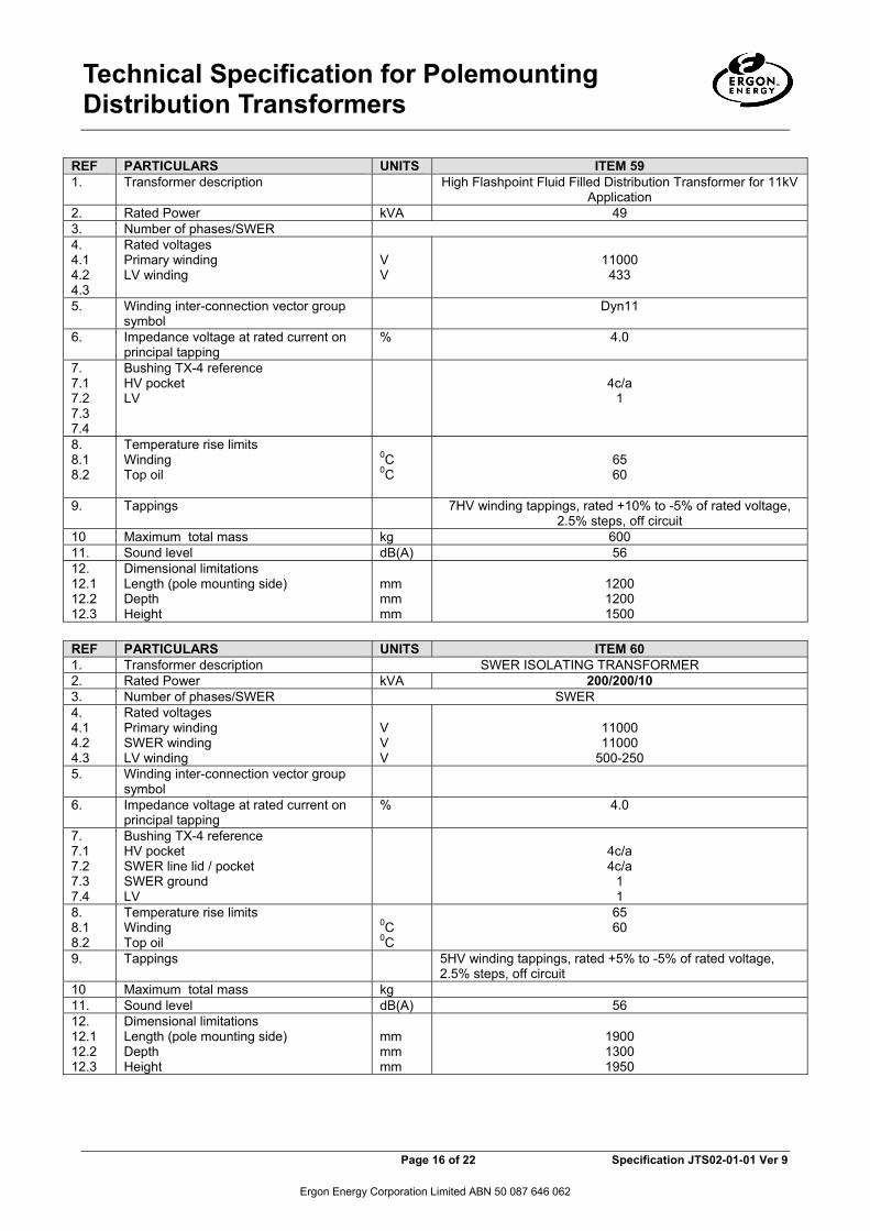
59 49 kV.A, three phase, 50 Hz, 11 kV/433-250 V ONAN, pole bolt transformer used in modular substation applications, complete with high flashpoint/ low fire risk insulating medium. To achieve rating as noted and ENA Doc 007 compliance, which may require use of an ENA Doc 007 Item of other kV.A size, whether de-rated or otherwise.
60 TRANSFORMER ISOLATING 11/11kV/500-250V, 200/200/10kVA, SWER, Pole Mounting, Tech Spec JTS 02-01-01 Item 60 (scm)

Technical Specification for Polemounting Distribution Transformers
Page 15 of 22 Specification JTS02-01-01 Ver 9
Ergon Energy Corporation Limited ABN 50 087 646 062
The following tables detail the specific design and performance requirements for the additional items.
REF PARTICULARS UNITS ITEM 52 ITEM 53 1. Transformer description STANDARD
DISTRIBUTION TRANSFORMER 33kV
SWER DISTRIBUTION TRANSFORMER
2. Rated Power kVA 50 50 3. Number of phases/SWER 1 SWER 4. 4.1 4.2
Rated voltages HV winding LV winding
V V
33000
250-500
11000
250-500 5. Winding inter-connection vector group
symbol
6. Impedance voltage at rated current on principal tapping % 3.3
7. 7.1 7.2 7.3 7.4
Bushing TX-4 reference HV lid/pocket SWER line lid / pocket SWER ground LV
-/6
1
5b/a 1 1
8. 8.1 8.2
Temperature rise limits Winding Top oil
0C 0C
65 60
9. Tappings 5 HV winding tappings, rated +5% to -5% of rated voltage, 2.5% steps, off circuit
10 Maximum total mass kg 1200 400 11. Sound level dB(A) 56 12. 12.1 12.2 12.3
Dimensional limitations Length (pole mounting side) Depth Height
mm mm mm
1300 1200 1600
1200 1200 1500
REF PARTICULARS UNITS ITEM 54 ITEM 55 ITEM 56 ITEM 57 ITEM 58 1. Transformer description SWER ISOLATING TRANSFORMER 2. Rated Power kVA 200/200/
10 100/100/10
200/200/10
200/200/10
100/100/10
3. Number of phases/SWER SWER 4. 4.1 4.2 4.3
Rated voltages Primary winding SWER winding LV winding
V V V
11000 12700 500-250
11000 19000 500-250
11000 19000 500-250
22000 12700 500-250
11000 11000 500-250
5. Winding inter-connection vector group symbol
6. Impedance voltage at rated current on principal tapping
% 4.0
7. 7.1 7.2 7.3 7.4
Bushing TX-4 reference HV pocket SWER line lid / pocket SWER ground LV
4c/a 5b/a 1 1
4c/a -/6 1 1
4c/a -/6 1 1
5b/a 5b/a 1 1
4c/a 4c/a 1 1
8. 8.1 8.2
Temperature rise limits Winding Top oil
0C 0C
65 60
9. Tappings 5HV winding tappings, rated +5% to -5% of rated voltage, 2.5% steps, off circuit
10 Maximum total mass kg 11. Sound level dB(A) 56 12. 12.1 12.2 12.3
Dimensional limitations Length (pole mounting side) Depth Height
mm mm mm
1900 1300 1950
Technical Specification for Polemounting Distribution Transformers
Page 16 of 22 Specification JTS02-01-01 Ver 9
Ergon Energy Corporation Limited ABN 50 087 646 062
REF PARTICULARS UNITS ITEM 59 1. Transformer description High Flashpoint Fluid Filled Distribution Transformer for 11kV
Application 2. Rated Power kVA 49 3. Number of phases/SWER 4. 4.1 4.2 4.3
Rated voltages Primary winding LV winding
V V
11000 433
5. Winding inter-connection vector group symbol
Dyn11
6. Impedance voltage at rated current on principal tapping
% 4.0
7. 7.1 7.2 7.3 7.4
Bushing TX-4 reference HV pocket LV
4c/a
1
8. 8.1 8.2
Temperature rise limits Winding Top oil
0C 0C
65 60
9. Tappings 7HV winding tappings, rated +10% to -5% of rated voltage, 2.5% steps, off circuit
10 Maximum total mass kg 600 11. Sound level dB(A) 56 12. 12.1 12.2 12.3
Dimensional limitations Length (pole mounting side) Depth Height
mm mm mm
1200 1200 1500
REF PARTICULARS UNITS ITEM 60 1. Transformer description SWER ISOLATING TRANSFORMER 2. Rated Power kVA 200/200/10 3. Number of phases/SWER SWER 4. 4.1 4.2 4.3
Rated voltages Primary winding SWER winding LV winding
V V V
11000 11000
500-250 5. Winding inter-connection vector group
symbol
6. Impedance voltage at rated current on principal tapping
% 4.0
7. 7.1 7.2 7.3 7.4
Bushing TX-4 reference HV pocket SWER line lid / pocket SWER ground LV
4c/a 4c/a
1 1
8. 8.1 8.2
Temperature rise limits Winding Top oil
0C 0C
65 60
9. Tappings 5HV winding tappings, rated +5% to -5% of rated voltage, 2.5% steps, off circuit
10 Maximum total mass kg 11. Sound level dB(A) 56 12. 12.1 12.2 12.3
Dimensional limitations Length (pole mounting side) Depth Height
mm mm mm
1900 1300 1950
Technical Specification for Polemounting Distribution Transformers
Page 17 of 22 Specification JTS02-01-01 Ver 9
Ergon Energy Corporation Limited ABN 50 087 646 062
7. Additional Requirements
The Tenderer shall provide details for the additional requirements for all items in Attachment 1.
7.1 Additional Requirement 1 - Low-voltage Current Transformers (CTs) and capability requirements to enable Distribution Transformer future-fitted Low-voltage (LV) Monitoring The Purchaser shall require Items 9, 10, 11, 13, 22, 23, 24, 26, 32, 33, 34, 35 in Attachment 1 to come fitted with the following:
• CTs, • Low-voltage voltage reference take offs, one per phase for each and all phases,
including for LV Neutral and LV Earth and associated bushing terminal brackets • The connection and or dismantling of the Voltage takeoff shall not affect in any way
of other electrical connection of plant or hardware items e.g. LV Surge Arrester Connection and therefore requires a separate means of attachment with or without LV Surge Arrester connection option and not direct from transformer bushing terminal palms.
• Mounting arrangements, and coiled and secured, umbilical flexible cable(s) to a junction box mounted for transport on the distribution transformer (with junction box positioning to meet the Purchaser’s requirements), all being ultraviolet stabilised and fit for outdoor, all-weather use.
The CT for items requiring the LV Monitoring must have the CT ratios correlated to the transformer kV.A capacity size and duty, including Emergency Cyclic Duty, as per AS 2374.7 and as specified in TS-481 LV Transformer Monitoring Capability Requirements for Pole Top and Ground Type Transformers The Tenderer to provide full details and information for each optional item so fitted.
7.2 Additional Requirement 2 - HV and LV Surge Arrester and ancillary equipment The Purchaser shall require Items 3, 5, 6, 9, 10, 11 and 13, in Attachment 1 to come fitted with the following:
7.2.1 HV Surge Arresters and ancillary equipment The transformers supplied shall be fitted with HV surge arresters including wildlife protection hoods on all HV Surge Arresters and on all Distribution Transformer Phase Bushings, cabling from each surge arrester to each respective phase bushing, for each phase, and all related accessories as required to fit complying Item 2 requirements of Specification TS449 Gapless Metal-Oxide Surge Arresters and TS449 General Requirements and wired in accordance, regarding each surge arrester to phase bushing bridging only, with the drawings 4920-A4 Sect 7 Page 1 and 4920-A4 Sect 7 Page 54. To prevent binding, different grade stainless steel nuts and bolts1 must be used together with anti-seizing lubricant on all bolt threads. 16 mm² stranded Cu. 11 kV polyethylene insulated, PVC sheathed, unscreened, UV stablised cable complying with AS/NZS 1429.1 must be used for all bridging.
1 For example, 316 grade bolts and washers fitted with 304 grade nuts.

Technical Specification for Polemounting Distribution Transformers
Page 18 of 22 Specification JTS02-01-01 Ver 9
Ergon Energy Corporation Limited ABN 50 087 646 062
For ENERGEX; the HV bushing must be fitted with the required termination “claw”-clamp and tinned, copper extension palm for copper bar attachment to the overhead line as per the above noted ENERGEX drawings in this clause 7.2 this technical specification. For ERGON; standard terminal palm connection will apply as per Ergon Energy drawing FILE: 5 01 1138 1 Page 61 E. The terminal palms must come fitted with tinned, copper extension palms that accommodate the Surge Arrester connection and also enable Live-Line techniques to enable changing of the Surge Arrester while the distribution transformer is in service by way of slotting the hole {of the surge arrester lead} of the tinned, copper extension palm.
7.2.2 LV Surge Arrester and ancillary equipment The transformers supplied shall be fitted with LV surge arresters complying with Item 1 requirements of TS449 Gapless Metal-Oxide Surge Arresters and TS449 General Requirements and wired in accordance with the drawings 891709-01, 891718-01, 891717-01 as applicable. To prevent binding, different grade stainless steel nuts and bolts2 must be used together with anti-seizing lubricant on all bolt threads. 50 mm² Cu. cable complying with AS/NZS 5000.1 must be used for all bridging. The cable must be PVC insulated (black) and UV stabilised.
7.2.3 Additional Markings The following additional markings are required:
• Rating/Terminal Marking Plate • The Purchaser’s Structured Plant Number (SPN) shall be added to the technical
details supplied on the manufacturers name plate in accordance with the ENA Doc 007 – 2006 Clause 5.12.1. The Structured Plant Numbers will be nominated in the purchase orders to the successful Tenderer. The SPN will be an eight digit number prefixed by two alphas (e.g. TD 12345678 for the distribution transformers)
• Tank Markings • In addition to the tank markings specified in Clause 5.12.10 of ENA Doc 007 – 2006,
Purchaser’s Structured Plnt Number shall be stencilled on the transformer tank, immediately below the Purchaser’s Item Identification Number in a similar manner.
• 7.2.4 Additional Information Required with the Routine Test Certificates
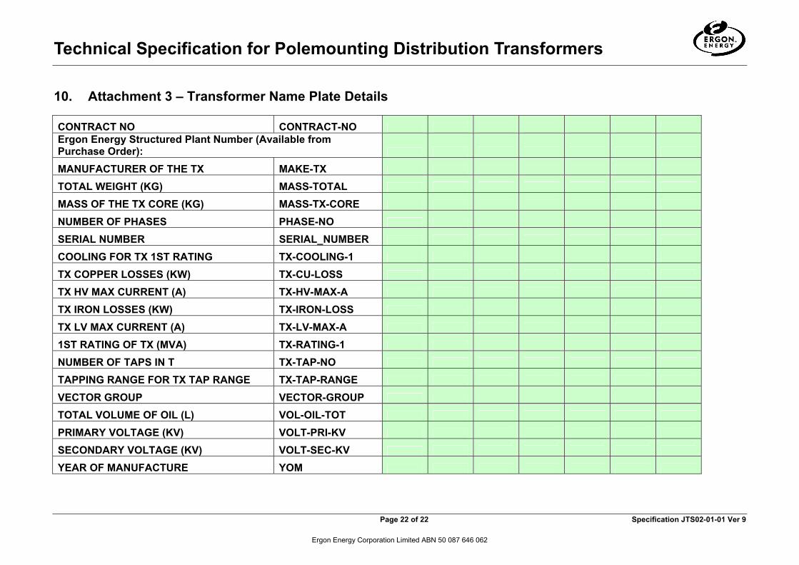
The successful Tenderer shall complete and return the Attachment 3 – Transformer Name Plate Details, as an Excel Spreadsheet, along with electronic copies of the relevant test reports (in accordance with ENA Doc 007-2006 Clause 6.9) for each transformer delivered by electronic mail to the Purchaser’s nominated email address - [email protected]
2 For example, 316 grade bolts and washers fitted with 304 grade nuts.

Technical Specification for Polemounting Distribution Transformers
Page 19 of 22 Specification JTS02-01-01 Ver 9
Ergon Energy Corporation Limited ABN 50 087 646 062
8. Attachment 1 – Additional Requirements
Full details and information of the Additional Requirements must be provided by the Tenderer. The Tenderer shall nominate in the table below whether or not they have supplied full details and information.
A. Additional Requirement Clause 7.1
Item No LV CTs and capability for
future-fitted LV Monitor (ref. C7.1) Yes / No
CT Class and Ratio
Item No LV CTs and capability for future-fitted LV Monitor (ref. C7.1) Yes / No
CT Class and Ratio
1 N/A N/A 30 2 N/A N/A 31 3 N/A N/A 32 4 N/A N/A 33 5 N/A N/A 34 6 N/A N/A 35 7 N/A N/A 36 8 N/A N/A 37 9 * * 38 10 * * 39 11 * * 40 12 N/A N/A 41 13 * * 42 14 N/A N/A 43 15 N/A N/A 44 16 N/A N/A 45 17 N/A N/A 46 18 N/A N/A 47 19 N/A N/A 48 20 N/A N/A 49 21 N/A N/A 50 22 * * 51 23 * * 52 24 * * 53 25 N/A N/A 54 26 * * 55 27 N/A N/A 56 28 N/A N/A 57 29 N/A N/A 58 59 60
* As conforming to the technical specifications JTS 02-01-01 (6) and TS 481B and given that the Tenderer has agreed to work with the Purchaser to provide standardised CT arrangements, including standardised CT ratios, for LV Monitoring which MAY vary final details and or arrangements.
SIGNATURE OF TENDERER: _________________________________

Technical Specification for Polemounting Distribution Transformers
Page 20 of 22 Specification JTS02-01-01 Ver 9
Ergon Energy Corporation Limited ABN 50 087 646 062
9. Attachment 2 – Risk Assessment
The Tenderer will complete the relevant items (as applicable): REF. PARTICULARS RESPONSE 1. Has the plant tendered been designed and manufactured in
compliance with the Queensland Workplace Health and Safety Plant Code of Practice and can documentary evidence be provided?
2. Does the design of the transformer, and the recommended methods for: Assembly, erection, operation, testing, inspection, maintenance of repairs, comply with the requirements of the Queensland Workplace Health and Safety Plant Code of Practice.
3. Has a risk assessment been performed on the plant tendered, which meets the requirements of AS/NZS 4360?
4. A copy of the above mentioned risk assessment will be included with the tender.
5. Mechanical Design Considerations 5.1 Is the plant designed to provide fault containment? 5.2 Is guarding provided for protection from moving parts, sharp
edges, hot/cold surfaces, etc?
5.3 Are AC and DC secondary terminals protected by insulation? 5.4 Is the plant designed to allow for routine maintenance without
encroaching upon electrical approach limits?
5.5 Is access to the plant necessary above 2.0 metres in height? 5.6 If yes to 5.5 confirm compliance with the Queensland
Workplace Health and Safety Codes of Practice and noted Major Hazards such as Risk Management and Work at Heights respectively.
5.7 What is the three dimensional clearances required for installation, operation, maintenance and testing of the plant.
5.8 Indicate if there is any special stability requirements for transportation, installation, operation and maintenance of the plant.
5.9 Is safe access provided for normal operational conditions?
6. Ergonomic Considerations:
6.1 When designing the plant what ergonomic standards were adopted for the following conditions:
6.2 (a) Working in confined spaces?
6.3 (b) Operating forces, eg opening and closing switches? 6.4 (c) Undesirable posture, eg installing HV cabling?

Technical Specification for Polemounting Distribution Transformers
Page 21 of 22 Specification JTS02-01-01 Ver 9
Ergon Energy Corporation Limited ABN 50 087 646 062
REF. PARTICULARS RESPONSE 6.5 (d) Access to components for installation, operation and
maintenance?
7. Manual Handling Considerations:
7.1 Is special lifting/handling equipment provided/required for individual components with a mass in excess of 15 kg?
7.2 Is labelling provided on individual components with a mass in excess of 15 kg?
7.3 Are lifting points/handles provided for individual components with a mass in excess of 15 kg?
7.4 Are lifting points/handles provided to ensure a balanced lift?
8. Hazardous Substance Considerations: 8.1 What hazardous substances are used/produced (including
after failure):
8.2 Are normal hazardous substance controls compatible with operational requirements?
8.3 Is a Safety Data Sheet available for all hazardous substances contained within the plant?
8.4 What are the expected hazardous substance changes/by products associated with the deterioration of a substance?
8.5 What are the hazards associated with handling hazardous substances after plant failure?
9. Environmental Considerations:
9.1 Does the plant contain components which could cause an environmental hazard should plant failure occur?
9.2 If yes to 9.1 please list these components 9.3 Can the tenderer demonstrate that the plant is designed to
limit the extent of environmental hazard should plant failure occur?
9.4. Do all symbols and labels provided on the plant conform to the requirements of the Queensland Workplace Health and Safety Act including the Plant Code of Practice?
9.5 What hazards, if any, are created should the plant be left in short or long term storage?
9.6 Indicate if special training, unique for this plant, is required. NAME OF TENDERER: ADDRESS OF TENDERER: SIGNATURE: FOR AND ON BEHALF OF TENDERER DATE: ______________________
Technical Specification for Polemounting Distribution Transformers
Page 22 of 22 Specification JTS02-01-01 Ver 9
Ergon Energy Corporation Limited ABN 50 087 646 062
10. Attachment 3 – Transformer Name Plate Details
CONTRACT NO CONTRACT-NO Ergon Energy Structured Plant Number (Available from Purchase Order):
MANUFACTURER OF THE TX MAKE-TX
TOTAL WEIGHT (KG) MASS-TOTAL
MASS OF THE TX CORE (KG) MASS-TX-CORE
NUMBER OF PHASES PHASE-NO
SERIAL NUMBER SERIAL_NUMBER
COOLING FOR TX 1ST RATING TX-COOLING-1
TX COPPER LOSSES (KW) TX-CU-LOSS
TX HV MAX CURRENT (A) TX-HV-MAX-A
TX IRON LOSSES (KW) TX-IRON-LOSS
TX LV MAX CURRENT (A) TX-LV-MAX-A
1ST RATING OF TX (MVA) TX-RATING-1
NUMBER OF TAPS IN T TX-TAP-NO
TAPPING RANGE FOR TX TAP RANGE TX-TAP-RANGE
VECTOR GROUP VECTOR-GROUP
TOTAL VOLUME OF OIL (L) VOL-OIL-TOT
PRIMARY VOLTAGE (KV) VOLT-PRI-KV
SECONDARY VOLTAGE (KV) VOLT-SEC-KV
YEAR OF MANUFACTURE YOM