overhead distribution transformers
TRANSCRIPT

Overhead DistributionTransformers
5-1000 KVA SINGLE PHASE • 30-500 KVA THREE PHASE • SUBMERSIBLES

POWER PARTNERS 2
About Power PartnersPower Partners manufactures poletypedistribution transformers that provide morethan 3,000 utilities in North America, CentralAmerica, the Middle East and Asia with electricpower for homes and businesses. PowerPartners’ poletype distribution transformersare specifically designed to serve residentialoverhead distribution loads. They are also suit-able for light commercial loads, industriallighting, and diversified power applications.
Power Partners provides a complete line ofoverhead transformers to meet the applicationsof any distribution system. The companymanufactures single-phase and three-phasepoletype transformers at 34.5 kV and below,in ratings from 5-1000 kVA single-phase and30-500 kVA three-phase. The Power Partnerscore-coil design provides optimum efficiencyand excellent mechanical, thermal and electricalperformance.
The Power Partners operation in Athens, GA,has achieved ISO 9001 certification. Theoperation, which was an ABB facility untilPower Partners purchased it in May 2003, hasover 60 years of manufacturing experience.
Manufacturing TechnologyOverhead distribution transformers manufac-tured by Power Partners offer cost-effectivesolutions for power distribution. The latestmanufacturing technology is utilized to maintainstate-of-the-art quality and productivity.Large vertical integration allows us to shiphigh quality products in the shortest possibleproduction cycle.
The Value of QualityPower Partners is committed to achieving totalcustomer satisfaction and industry leadershipthrough continuous process improvement.The company’s employees are team-based andmeasurement focused, and their work is basedon highly disciplined processes. The companyis innovative, reliable and driven to providehigh quality and high value, and to meet eachdelivery commitment. We want Power Partnersto be recognized as a company that exceedscustomers’ expectations.
An Industry LeaderWorking together with our Power Partners’ manufacturer representatives, we have alliances with major utilities and businesses around the world providing products and services to meet all their needs. Together, we are a dominant force in the industry.
POWER PARTNERS 3
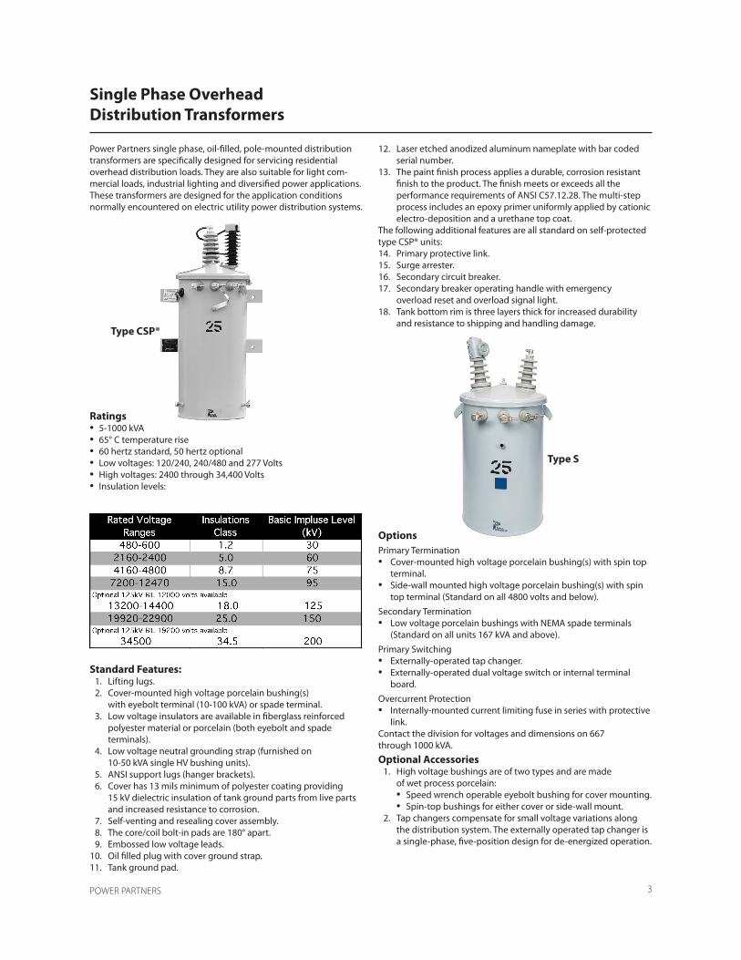
Power Partners single phase, oil-filled, pole-mounted distribution transformers are specifically designed for servicing residential overhead distribution loads. They are also suitable for light com-mercial loads, industrial lighting and diversified power applications. These transformers are designed for the application conditions normally encountered on electric utility power distribution systems.
Ratings• 5-1000 kVA• 65° C temperature rise• 60 hertz standard, 50 hertz optional• Low voltages: 120/240, 240/480 and 277 Volts• High voltages: 2400 through 34,400 Volts• Insulation levels:
Standard Features: 1. Lifting lugs. 2. Cover-mounted high voltage porcelain bushing(s) with eyebolt terminal (10-100 kVA) or spade terminal. 3. Low voltage insulators are available in fiberglass reinforced polyester material or porcelain (both eyebolt and spade terminals). 4. Low voltage neutral grounding strap (furnished on 10-50 kVA single HV bushing units). 5. ANSI support lugs (hanger brackets). 6. Cover has 13 mils minimum of polyester coating providing 15 kV dielectric insulation of tank ground parts from live parts and increased resistance to corrosion. 7. Self-venting and resealing cover assembly. 8. The core/coil bolt-in pads are 180° apart. 9. Embossed low voltage leads. 10. Oil filled plug with cover ground strap.11. Tank ground pad.
12. Laser etched anodized aluminum nameplate with bar coded serial number. 13. The paint finish process applies a durable, corrosion resistant finish to the product. The finish meets or exceeds all the performance requirements of ANSI C57.12.28. The multi-step process includes an epoxy primer uniformly applied by cationic electro-deposition and a urethane top coat.The following additional features are all standard on self-protected type CSP® units: 14. Primary protective link. 15. Surge arrester. 16. Secondary circuit breaker. 17. Secondary breaker operating handle with emergency overload reset and overload signal light. 18. Tank bottom rim is three layers thick for increased durability and resistance to shipping and handling damage.
OptionsPrimary Termination• Cover-mounted high voltage porcelain bushing(s) with spin top terminal.• Side-wall mounted high voltage porcelain bushing(s) with spin top terminal (Standard on all 4800 volts and below).Secondary Termination• Low voltage porcelain bushings with NEMA spade terminals (Standard on all units 167 kVA and above).Primary Switching• Externally-operated tap changer.• Externally-operated dual voltage switch or internal terminal board.Overcurrent Protection• Internally-mounted current limiting fuse in series with protective link.Contact the division for voltages and dimensions on 667through 1000 kVA.Optional Accessories 1. High voltage bushings are of two types and are made of wet process porcelain: • Speed wrench operable eyebolt bushing for cover mounting. • Spin-top bushings for either cover or side-wall mount. 2. Tap changers compensate for small voltage variations along the distribution system. The externally operated tap changer is a single-phase, five-position design for de-energized operation.
Single Phase OverheadDistribution Transformers
Type S
Type CSP®
POWER PARTNERS 4
3. A dual voltage switch permits use of the same transformer on distribution systems with different system voltages. 4. The CSP® protection package consists of four related components that work together to provide complete self- contained protection against surge currents, short circuits and overloads: • The protective link removes an internally-faulted transformer from the primary line, maintaining service to other customers on the line not served by the faulted unit.
• The MOV polymer arresters handle surges of 65,000 amperes (small block) and 100,000 amperes (large block). • Secondary circuit breakers protect against overloads and external short circuits. • An optional current limiting fuse supplements the protective link when the fault current exceeds the link’s rating. 5. Stainless steel tanks and covers are available. 6. EZ-Lift Eyebolt 7. Natural Ester Oils 8. IFD
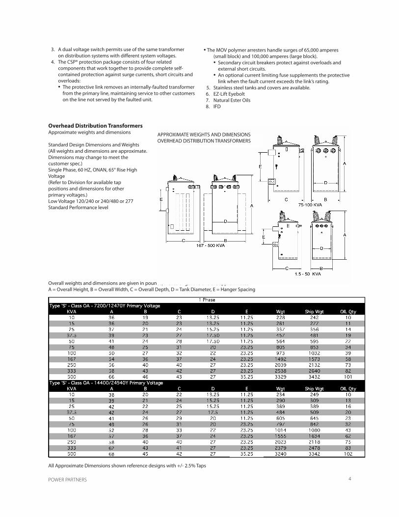
Overall weights and dimensions are given in pounds, inches or gallons and are approximatesA = Overall Height, B = Overall Width, C = Overall Depth, D = Tank Diameter, E = Hanger Spacing
Overhead Distribution TransformersApproximate weights and dimensions
Standard Design Dimensions and Weights(All weights and dimensions are approximate.Dimensions may change to meet the customer spec.)Single Phase, 60 HZ, ONAN, 65° Rise HighVoltage(Refer to Division for available tappositions and dimensions for otherprimary voltages.)Low Voltage 120/240 or 240/480 or 277Standard Performance level
All Approximate Dimensions shown reference designs with +/- 2.5% Taps
APPROXIMATE WEIGHTS AND DIMENSIONSOVERHEAD DISTRIBUTION TRANSFORMERS

POWER PARTNERS 5
Power Partners offers four basic transformer types: S, SP, CP and CSP®. Together they represent a wide range of protective capabilities to meet nearly every application. For transformers supplied with overcurrent protection, the user must assure coordination with system protective devices. Failure to do so will defeat the purpose of such protection.
Conventional “S” TransformersThis type transformer contains no protection equipment.Therefore, lightning, fault and overload protection forthese transformers must be provided by purchaser installed,auxiliary protective devices.
Conventional “S” with Protective LinkThe protective link is the least expensive device mounted in the transformer to protect the system from a defective transformer. Whenever there is an internal failure the resulting fault current will cause the protective link to blow, isolating the transformer from the primary feeder.
Surge-Protecting “SP” TransformersThe “SP” transformers include transformer-mounted lightning arresters and internally-mounted high voltage protective links, but omit the internally-mounted low voltage circuit breaker. These transformers are used in locations where lightning is a problem. However, because the protective link protects the system only from outages due to internal transformer failure, overload protection, if desired, must be provided by external fuses.
Current-Protecting “CP” TransformersThe “CP” transformers are equipped with the internally mountedlow-voltage circuit breaker and high voltage protective links, but omit the lightning arresters. These transformers are used in locations where lightning is not a problem. The arrester may be crossarm-mounted if surge protection is desired.
The breaker and protective link are coordinated such that any fault or short circuit on the secondary side of the transformer will trip the breaker before the protective link operates, taking the load off the transformer before the core/coil is damaged.
Self-Protected “CSP®” TransformersThe CSP® coordinated protection package is available asan option on Power Partners overhead distribution transformersfor increased protection against surge currents,short circuits, and overloads.
Features 1. Protective Link a) Removes an internally-faulted transformer from the primary line. b) Operates at 8 to 14 times normal full load current. 2. Secondary Circuit Breaker a) Protects against overloads and external short circuits. b) Coordinated with protective link, trips on an external short or overload before the link blows, and only if the overload is large or continuous. c) If overload is small or temporary, a load management light signals the need for change-out to a larger unit for more optimized transformer loading. 3. MOV Polymer Arrester Provides protection from lightning and switching surges. 4. Optional partial-range current limiting fuse (in series with protective link) a) Limits the maximum current in the circuit. b) Reduces current to zero in less than one-half cycle. c) Minimizes the possibility of eventful failure. 5. Tank bottom rim is three layers thick for increased durability and resistance to shipping and handling damage.
The CSP® protection package is available on single phase and three phase overhead distribution transformers in the following ratings:• Single Phase, LV 120/240, 10-100 kVA• Single Phase, LV 240/480, 10-167 kVA• Three Phase, 30-150 kVA
Transformer Protection Packagefor Overhead Distribution Transformers
Type S
Type CSP®

POWER PARTNERS 6
Class Designations1. Type CSP®, above 5 kV, 5-100 kVA.
Class A: Two fully-insulated high voltage bushings, twoarresters, two protective links and external breaker handle.Suitable for application on either wye or delta distributionsystems. Single-position pole mounting inaccordance with latest ANSI standards.
Class B-1: Two fully-insulated high voltage bushings,one arrester, two protective links and external breakerhandle. Normally applied on solidly grounded systems.
Class B-2: One fully-insulated high voltage bushing, onearrester, one protective link and external breaker handle.Suitable only for application on solidly grounded distributionsystems. Single-position pole mounting in accordancewith latest ANSI standards.
Class B-3: Same as class B-2 except with two-positionmounting. On 5 through 50 kVA only.2. Type CSP®, 5 kV and below, 5-100 kVA. Similar to Type CSP®
above 5 KV except: • Sidewall-mounted primary bushings. • Class B-2 and B-3 not available.1. Type S, above 5 kV, 5-500 kVA.
Class A: Two fully-insulated high voltage bushings, suitablefor application on either wye or delta distributionsystems. Single-position pole mounting in accordancewith the latest ANSI standards.
Class B-2: One fully-insulated high voltage bushing, suitableonly for application on solidly grounded distributionsystems. Single-position pole mountingin accordance with the latest ANSI standards.
Class B-3: Same as class B-2 except with two-positionmounting. On 5 through 50 kVA only.2. Type S, 5 kV and below, 10-500 kVA. Similar to Type S, above 5 kV, except: • Sidewall-mounted primary bushings.
• Only Class A is available.

POWER PARTNERS 7
The exclusive center-bolt cover design is standard on allPower Partners overhead transformers, 5-1000 kVA singlephase and 30-500 kVA three phase. The cover assembly isunique in both operation and design. The unit offers anextraordinary high withstand capability and an extra marginof safety.
Advantages• Static and dynamic pressure relief provided by unique venting and resealing capability.• Increased safety provided through higher tank withstand capability and automatic pressure venting during cover removal.• No auxiliary pressure relief device is required.• Extra insulation provided by thick epoxy coating.• Increased resistance to corrosion provided by sloped cover and thick coating.• Increased resistance to leaks and breathing provided by unique gasketing system.• Simplified maintenance provided by single cover bolt.
Features1. Center-bolt cover, cover beam and beam support lug system provide: a) Self-venting and resealing which meets ANSI specifications eliminating the need for an auxiliary pressure relief device. b) Tank withstand capability in excess of the requirements of NEMA TR1.2. Increased tank withstand capability and automatic pressure relief during cover removal result in increased safety.3. Electrostatically-applied epoxy coating is a minimum of 13 mils, providing an average of 15 kV dielectric strength to provide extra insulation and protection from corrosion.4. The 15° slope of cover prevents moisture from collecting and increases resistance to corrosion and leaking.5. Continuous hollow nitrile gasket, raised and flat bushing embossments, undercut gasket seats on bushings, and copper-encased cover bolt gasket provide increased resistance to leaks and breathing.6. Center cover bolt provides easy cover removal compared to chime ring design, resulting in lower maintenance cost.7. Tank bottom rim is three layers thick for increased durability and resistance to shipping and handling damage.
Standard Compliance
A. Pressure Venting and ResealingThe self-venting cover design meets the pressure ventingand resealing requirements of ANSI C57.12.20-2017, paragraph7.2.5.2.
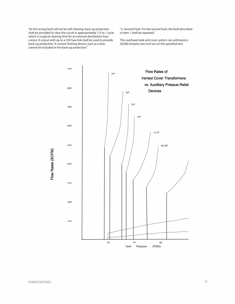
“A cover assembly designed for relief of excessive pressureshall remain effectively sealed for overloads and externalsecondary short circuits of the magnitude and durationallowed by industry standards and loading guides, butshall relieve pressure at a minimum of 8 lbf/in2, gage (56kPa) if designed to reseal; or at a minimum of 20 lbf/in2,gage (138 kPa) if designed for pressure relief withoutresealing. Such operation shall occur before other componentsof the tank are ruptured or displaced, and the covershall remain in position. Manual means of venting the tankbefore removal of cover shall be provided.”No auxiliary pressure relief device is required on PowerPartners overhead distribution transformers. The flowrate of the center-bolt cover after venting is significantlyhigher than that of auxiliary pressure relief devicesresulting in increased safety and higher tank withstandcapability.
B. Tank withstandThe Power Partners overhead tank and cover design providetank withstand capability far in excess of the requirementsof NEMA TR1-2000, Part 2, Page 6, Section D:“Test No. 1 – An Arcing Fault in an Enclosure”“1. First Fault. A simulated internal fault shall be provided.This fault shall consist of a 1-inch arc gapmounted horizontally and located 1 inch above the coreclamps. This gap shall be bridged initially by a 0.0605-inch diameter or smaller copper wire. The gap shall beconnected between the high-voltage terminals or fromone high-voltage terminal to ground. The mountingblocks or terminals of the gap shall consist of copperbearingmaterial and shall have flat surfaces from 1/2 to3/4 inch in diameter or in width. These gaps shall bedesigned to maintain this 1-inch arc gap for the durationof the fault. The transformer coil shall not be electricallyconnected in this test circuit. The power source shall be7.2 kV and adjusted to supply a current of 8000 rms symmetricalamperes.”
Center-Bolt Cover Design
POWER PARTNERS 8
“As this arcing fault will not be self-clearing, back-up protectionshall be provided to clear the circuit in approximately 1/2 to 1 cycle which is a typical clearing time for an external distribution fuse cutout. A cutout with up to a 25K fuse link shall be used to provide back-up protection. A current-limiting device, such as a fuse, cannot be included in the back-up protection.”
“2. Second Fault. For the second fault, the fault described in item 1 shall be repeated.”
This overhead tank and cover system can withstand a20,000 Ampere one-inch arc on the specified test.
10 20 30 Tank Pressure (PSIG)
100
200
300
500
400
600
900
700
800
Flow Rates of
Vented Cover Transformers
vs. Auxilliary Pressue Relief
Devices
Flo
w R
ates
(SC
FM)
27"
24"
22"
20"
17.5"
15.25"
POWER PARTNERS 9
An internal low voltage spark gap has been developed asa means of protection for distribution transformersagainst secondary side surges. The Electric UtilityIndustry has been concerned about transformer failuresattributed to secondary surges, although the failure rateis estimated to be less than 0.5% per year. The entiresubject is very complex, but the phenomenon is verymuch related to system parameters, such as, house andpole ground resistance, length and type of service drop,and transformer load. The surge impedance of the transformercoil is also a significant factor, resulting in unitslarger than 50 kVA being typically immune from this typeof failure. The Power Partners spark gap will providethe same degrees of protection as any other methodpresently available, and at a significantly lower cost.
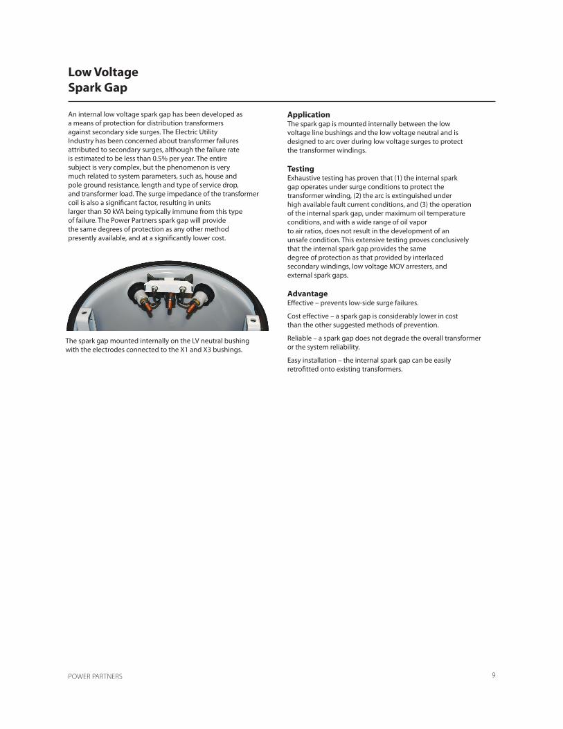
ApplicationThe spark gap is mounted internally between the lowvoltage line bushings and the low voltage neutral and isdesigned to arc over during low voltage surges to protectthe transformer windings.
TestingExhaustive testing has proven that (1) the internal sparkgap operates under surge conditions to protect thetransformer winding, (2) the arc is extinguished underhigh available fault current conditions, and (3) the operationof the internal spark gap, under maximum oil temperatureconditions, and with a wide range of oil vaporto air ratios, does not result in the development of anunsafe condition. This extensive testing proves conclusivelythat the internal spark gap provides the samedegree of protection as that provided by interlacedsecondary windings, low voltage MOV arresters, andexternal spark gaps.
AdvantageEffective – prevents low-side surge failures.
Cost effective – a spark gap is considerably lower in costthan the other suggested methods of prevention.
Reliable – a spark gap does not degrade the overall transformeror the system reliability.
Easy installation – the internal spark gap can be easilyretrofitted onto existing transformers.
Low VoltageSpark Gap
The spark gap mounted internally on the LV neutral bushingwith the electrodes connected to the X1 and X3 bushings.

POWER PARTNERS 10
“JUMBO” Distribution Transformers are designed assingle phase, two-winding transformers—specificallyfor “Step-Down” applications.
Standard Features 1. Lo-Hi-Lo coil design divides the short circuit force between low-high spaces increasing the short circuit strength of the coil. 2. Two winding construction yields a much higher impedance than is characteristic of an auto transformer which helps limit the mechanical forces the unit must sustain during fault duty. 3. Progressively wound coils with adhesive resins on thermally upgraded insulating paper provide increased short circuit and thermal strength. 4. Sheet conductor in LV windings enables the electrical centers in the high and low to align themselves minimizing the vertical component of short circuit forces. 5. Reinforced core-coil assembly provides greater short circuit withstand capability.
6. Prototype testing insures the Jumbo design can meet industry short circuit standards and provide reliable service. 7. Self-venting and resealing cover eliminates the need for an auxiliary pressure relief device and offers increased safety through higher tank withstand. 8. ANSI support lugs (hanger brackets) are rod-welded to the tank wall for added strength. 9. Anodized aluminum laser inscribed nameplate offers longer term readability. 10. Lifting lugs are positioned directly opposite the cover beam lugs, reducing the chance of the tank going out of round when lifted. 11. Cover mounted high voltage porcelain bushings with eyebolt terminals are mounted on flat embossments on the cover and have undercut gasket seats for improved sealing. The eyebolt connectors are cast bronze plated with tin. 12. Low voltage porcelain bushings with clamp-type terminals provide ease in making secondary terminations. 13. Arrester mounting pads are resistance welded to the tank wall, completely and uniformly filling the surfaces where pad and tank wall join, to provide greater strength. 14. The paint finish process applies a durable, corrosion resistant finish to the product. The finish meets or exceeds all the performance requirements of ANSI C57.12.28. The multi-step process includes an epoxy primer uniformly applied by cationic electrodeposition and a urethane top coat. 15. Tank bottom rim is three layers thick for increased durability and resistance to shipping and handling damage.
Ratings• 50-500 kVA• 65°C Rise• 60 Hertz standard, 50 Hertz optional• High voltages: 7200, 14400 and 19920• Low voltages: 2400, 4800, 7200, 7620, 7970
JUMBO “Step Down”Overhead Distribution Transformer

POWER PARTNERS 11
Standard Design Dimensions and Weights
All Approximate Dimensions shown reference designs with +/- 2.5% Taps
Overall weights and dimensions are given in pounds, inches or gallons and are approximatesA = Overall Height, B = Overall Width, C = Overall Depth, D = Tank Diameter
JUMBO LIQUID IMMERSED OVERHEAD DISTRIBUTION TRANSFORMERTYPE S, HV ABOVE 5 KV, > 100 KVA
POWER PARTNERS 12
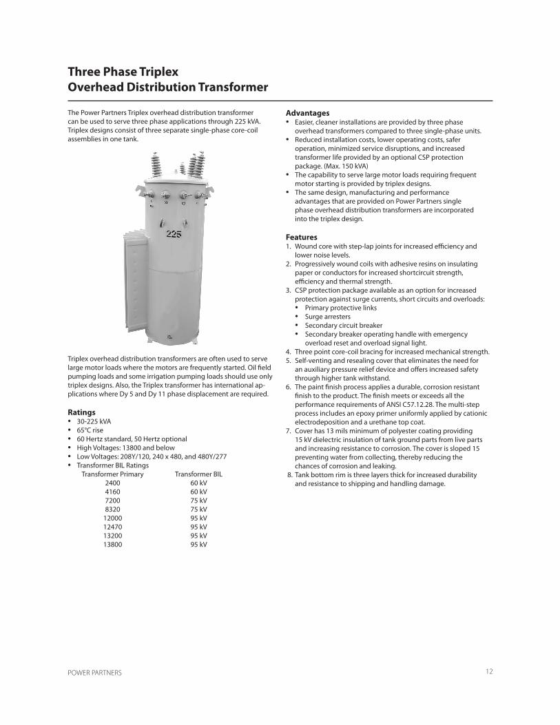
The Power Partners Triplex overhead distribution transformercan be used to serve three phase applications through 225 kVA. Triplex designs consist of three separate single-phase core-coil assemblies in one tank.
Triplex overhead distribution transformers are often used to serve large motor loads where the motors are frequently started. Oil field pumping loads and some irrigation pumping loads should use only triplex designs. Also, the Triplex transformer has international ap-plications where Dy 5 and Dy 11 phase displacement are required.
Ratings• 30-225 kVA• 65°C rise• 60 Hertz standard, 50 Hertz optional• High Voltages: 13800 and below• Low Voltages: 208Y/120, 240 x 480, and 480Y/277• Transformer BIL Ratings Transformer Primary Transformer BIL 2400 60 kV 4160 60 kV 7200 75 kV 8320 75 kV 12000 95 kV 12470 95 kV 13200 95 kV 13800 95 kV
Advantages• Easier, cleaner installations are provided by three phase overhead transformers compared to three single-phase units.• Reduced installation costs, lower operating costs, safer operation, minimized service disruptions, and increased transformer life provided by an optional CSP protection package. (Max. 150 kVA)• The capability to serve large motor loads requiring frequent motor starting is provided by triplex designs.• The same design, manufacturing and performance advantages that are provided on Power Partners single phase overhead distribution transformers are incorporated into the triplex design.
Features1. Wound core with step-lap joints for increased efficiency and lower noise levels.2. Progressively wound coils with adhesive resins on insulating paper or conductors for increased shortcircuit strength, efficiency and thermal strength.3. CSP protection package available as an option for increased protection against surge currents, short circuits and overloads: • Primary protective links • Surge arresters • Secondary circuit breaker • Secondary breaker operating handle with emergency overload reset and overload signal light.4. Three point core-coil bracing for increased mechanical strength.5. Self-venting and resealing cover that eliminates the need for an auxiliary pressure relief device and offers increased safety through higher tank withstand.6. The paint finish process applies a durable, corrosion resistant finish to the product. The finish meets or exceeds all the performance requirements of ANSI C57.12.28. The multi-step process includes an epoxy primer uniformly applied by cationic electrodeposition and a urethane top coat.7. Cover has 13 mils minimum of polyester coating providing 15 kV dielectric insulation of tank ground parts from live parts and increasing resistance to corrosion. The cover is sloped 15 preventing water from collecting, thereby reducing the chances of corrosion and leaking. 8. Tank bottom rim is three layers thick for increased durability and resistance to shipping and handling damage.
Three Phase TriplexOverhead Distribution Transformer

POWER PARTNERS 13
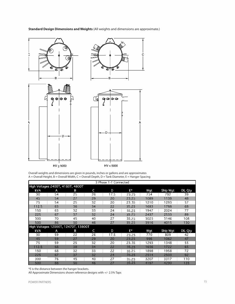
Standard Design Dimensions and Weights (All weights and dimensions are approximate.)
Overall weights and dimensions are given in pounds, inches or gallons and are approximatesA = Overall Height, B = Overall Width, C = Overall Depth, D = Tank Diameter, E = Hanger Spacing
*E is the distance between the hanger brackets.
POWER PARTNERS 14
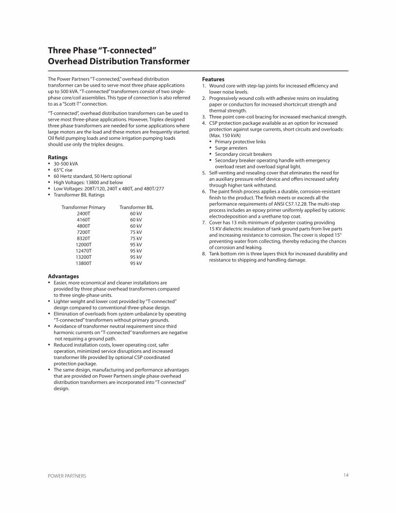
The Power Partners “T-connected,” overhead distributiontransformer can be used to serve most three phase applicationsup to 500 kVA. “T-connected” transformers consist of two single-phase core/coil assemblies. This type of connection is also referred to as a “Scott-T” connection.
“T-connected”, overhead distribution transformers can be used to serve most three-phase applications. However, Triplex designed three phase transformers are needed for some applications where large motors are the load and these motors are frequently started. Oil field pumping loads and some irrigation pumping loadsshould use only the triplex designs.
Ratings• 30-500 kVA• 65°C rise• 60 Hertz standard, 50 Hertz optional• High Voltages: 13800 and below• Low Voltages: 208T/120, 240T x 480T, and 480T/277• Transformer BIL Ratings
Transformer Primary Transformer BIL 2400T 60 kV 4160T 60 kV 4800T 60 kV 7200T 75 kV 8320T 75 kV 12000T 95 kV 12470T 95 kV 13200T 95 kV 13800T 95 kV
Advantages• Easier, more economical and cleaner installations are provided by three phase overhead transformers compared to three single-phase units.• Lighter weight and lower cost provided by “T-connected” design compared to conventional three-phase design.• Elimination of overloads from system unbalance by operating “T-connected” transformers without primary grounds.• Avoidance of transformer neutral requirement since third harmonic currents on “T-connected” transformers are negative not requiring a ground path.• Reduced installation costs, lower operating cost, safer operation, minimized service disruptions and increased transformer life provided by optional CSP coordinated protection package.• The same design, manufacturing and performance advantages that are provided on Power Partners single phase overhead distribution transformers are incorporated into “T-connected” design.
Features1. Wound core with step-lap joints for increased efficiency and lower noise levels.2. Progressively wound coils with adhesive resins on insulating paper or conductors for increased shortcircuit strength and thermal strength.3. Three point core-coil bracing for increased mechanical strength.4. CSP protection package available as an option for increased protection against surge currents, short circuits and overloads: (Max. 150 kVA) • Primary protective links • Surge arresters • Secondary circuit breakers • Secondary breaker operating handle with emergency overload reset and overload signal light.5. Self-venting and resealing cover that eliminates the need for an auxiliary pressure relief device and offers increased safety through higher tank withstand.6. The paint finish process applies a durable, corrosion-resistant finish to the product. The finish meets or exceeds all the performance requirements of ANSI C57.12.28. The multi-step process includes an epoxy primer uniformly applied by cationic electrodeposition and a urethane top coat.7. Cover has 13 mils minimum of polyester coating providing 15 KV dielectric insulation of tank ground parts from live parts and increasing resistance to corrosion. The cover is sloped 15° preventing water from collecting, thereby reducing the chances of corrosion and leaking.8. Tank bottom rim is three layers thick for increased durability and resistance to shipping and handling damage.
Three Phase “T-connected”Overhead Distribution Transformer
POWER PARTNERS 15
Standard Design Dimensions and Weights (All weights and dimensions are approximate.)
Overall weights and dimensions are given in pounds, inches or gallons and are approximatesA = Overall Height, B = Overall Width, C = Overall Depth, D = Tank Diameter, E = Hanger Spacing
*E is the distance between the hanger brackets.All Approximate Dimensions shown reference designs with +/- 2.5% Taps

POWER PARTNERS 16
The Power Partners commitment to manufacture qualitydistribution transformers is backed by a series of transformertests used to verify conformance to performancecharacteristics outlined in the latest revisions of ANSIC57.12.00 and ANSI C57.12.90. These identified testsare part of the Quality System which is audited annuallyby an accredited third party auditor to ISO Standards.
Testing ProgramFactory tests are performed on a transformer to confirmthat it is properly designed and constructed to carryrated load and that it will withstand the conditions it willbe exposed to in service.
Each transformer manufactured by Power Partners mustundergo a series of tests.1. Polarity, Phase-Relation, and Ratio2. Applied Voltage Test of the HV3. Applied Voltage Test of the LV4. Induced Voltage Test5. No-Load (Excitation) Loss and Excitation Current6. Impedance Voltage and Load Loss7. Full Wave Impulse
Test FacilitiesThe multi-station, automated test facilities are operatedby process control computers. Required interaction withtest floor personnel is minimal with the computers initiatingand monitoring each test, and then analyzing thetest results feedback. The computers are programmed toconduct tests according to ANSI standards, and accordingto the ratings of each transformer style, the test floorcomputers will initiate appropriate test setups, compareresults with established ANSI standard limits, and determineacceptance for each tested unit.
The test results for each unit are recorded and stored oncomputer files for access and analysis.
Polarity, Phase-Relation, and Ratio TestsThese tests verify proper phase-relation (three phase),ratio, and polarity (single phase) of the transformer undertest. To pass, a unit must demonstrate the proper polarityor phase-relation and have a turns ratio within one-half ofone percent of the nominal voltage ratio.
Applied Voltage Test of the HVThis test checks the dielectric integrity of insulationstructures between the high voltage and low voltage, andbetween the high voltage and ground. A pass/fail decisionis made by monitoring the test current intensity. Ifthe resulting current is larger than specified normal leakageand capacitive currents, the unit is rejected. This testis omitted for transformers with a permanently groundedhigh voltage winding.
Applied Voltage Test of LVThis dielectric test is similar to the Applied Voltage testof the high voltage circuitry except that the integrity ofinsulation structures between the low voltage and thehigh voltage, and between the low voltage and ground ischecked. A pass-fail decision is made by monitoring thetest current intensity. If the resulting current is largerthan specified normal leakage and capacitive current,the unit is rejected.
Induced Voltage TestThe principal purpose of this test is to verify the dielectricstrength of turn to turn, layer to layer, phase to phase,and other insulation structures within the transformerwindings by inducing an overvoltage condition (at higherthan normal frequency to avoid saturation of the core).The test current is monitored, and if it exceeds limitsspecified for each transformer, the unit is rejected.
No-Load Loss and Excitation CurrentThis test measures the no-load (excitation) loss and thetransformer exciting current with rated voltage applied.If the exciting current and/or the no-load loss exceed thelimits specified, the transformer is rejected.Circuit Breaker Test (for CSP transformers only)
Impedance Voltage and Load LossThis test measures the load loss and the impedance voltageat rated current. The load loss and the impedancevoltage must be within specified limits.
Full Wave ImpulseThe impulse test is one of several tests designed to verifythe dielectric strength of the many insulation structureswithin the distribution transformer against line voltagesurges. It is performed to comply with ANSI standardsand for quality assurance. The change in the ANSI standardin 1993 required all manufacturers to install faultdetection sensitive enough to detect a single turn short.
Continuity CheckThis test is performed on all transformers to verify transformercircuit and component integrity. This test is performedwith an ohmmeter to verify that the internalwiring is correct.
The transformer’s nameplate is compared to manufacturinginformation for style, serial number, kVA, HV rating,LV rating, tap voltages, impedance, conductor materialsand coil BIL rating. The bushings, electrical accessories,and fuses are verified.
DistributionTransformer Testing

POWER PARTNERS 17
Special Tests
Some tests are performed at the option of the customer.
Sound TestingANSI standards define the required sound levels fortransformer but some customers specify reduced soundlevels. The sound generated by a transformer is affectedby the core geometry, flux density, tank design, and thequality of assembly of all the transformer componentsinto a completed unit. Sound tests are made with theunit powered at 100% and 110% of rated voltage underno-load conditions.
Temperature TestsCore losses and coil losses are the primary sources ofheating within the transformer. Our transformers areguaranteed to have an average coil winding temperatureof no more than 65° C rise over ambient air temperaturewhen operated at rated voltage and load conditions.The temperature test is performed to determine thethermal characteristics of the transformer and to verifythat they are within design limits.
CalibrationTest equipment is calibrated on a scheduled basis bytrained technicians. Calibration records are maintained inaccordance with the Quality System procedures. Theseare audited annually by a third party in accordance to ISO.
Short Circuit Withstand CapabilitiesDistribution transformers are subjected to external shortcircuits on the secondary side. Such external faults candevelop on the service line, in the house wiring or inconnected loads due to numerous environmental reasons.These faults can be line-to-ground, double line-togroundor line-to-line.
To meet these operating conditions, the AmericanNational Standard Institute (ANSI) has set standards concerningshort circuit withstand capability. These standards require that distribution transformers shall be designed and constructed to withstand the mechanical and thermal stresses produced by these external short circuits.
The current standards relating to short circuit strengthare ANSI C57.12.00 which sets the short circuit withstandrequirements for distribution transformers and ANSIC57.12.90 which provides procedures for short circuit testing.
For distribution transformers, the magnitude of the shortcircuit current, the numbers of short-circuit tests and theduration of each short circuit test are defined by ANSIstandards as follows.
A. Magnitude
B. Number of TestsEach phase of the transformer shall be subjected to atotal of six tests, four with symmetrical fault currents andtwo with asymmetrical fault currents.
C. Duration of Short Circuit TestsWhen short circuit tests are performed the duration ofeach test shall be 0.25 s except that one test satisfying thesymmetrical current requirement shall be made for alonger duration on distribution transformers. The durationof the long test in each case shall be as follows:
Category I: T=1250/I2
Where T is the duration in seconds,
And I=Isc/IR=symmetrical short circuit current, in multiplesof normal base current except I shall not exceed the maximumsymmetrical current magnitudes listed in A.
Where Isc=IR/ZT=symmetrical short circuit current, inrms amperes
IR=rated current on the given tap connection, in rmsamperes
ZT=transformer impedance on the given tap connectionin per unit on the same apparent power base as IR
Category II: T=1.0 second
Criteria of Satisfactory PerformanceAccording to ANSI Standards a unit is considered to havepassed the test if it passes a visual inspection and dielectrictests. Recommended additional checks includeexamination of wave shape of terminal voltage and current,leakage impedance measurement and excitationcurrent test. (Refer to ANSI C57.12.90.)
The standard allows the following variations in the leakageimpedance:
ZT (Per Units) Percentage Variation0.0299 or less 22.5-500 (ZT)0.0300 or more 7.5
ZT=per unit impedance of the transformer
POWER PARTNERS 18
The Power Partners factory utilizes a paint finish processcalled “2CEC”, a trademark for a two-coat cathodic electro- deposition paint process. This new advanced coating technique maintains the structural integrity of transformers that are subjected to the long-term corrosive environments of coastal areas and industrial contaminants.
Paint ProcessCathodic electrodeposition of paint occurs when directcurrent is applied to positively charged resin micellesdispersed in water. The resin micelles migrate toward thecathode (transformer tank) and are deposited in a processknown as electrophoresis. As the process continues,the thickness of the deposit builds, resistance increases,and the film reaches a thickness limit. The most accessibleareas are coated first, but as the resistance increases,less accessible areas coat, producing a highly uniformfilm build. Two-coat cathodic electrodeposition is theapplication of two coats of paint (epoxy primer/acrylicurethane topcoat).
Paint PretreatmentPrior to welding to the tank shell, stamped external hardwaresuch as hanger brackets and lifting lugs are vibratoryfinished to remove burrs and insure a smooth radiusedge to allow consistent edge coating.
An eight-stage dip process provides two cleaning steps tocompletely remove lubricants and soils. A zinc phosphatecoating is applied to enhance corrosion protectionby providing tighter, more consistent coating than thetypically used iron phosphate. The use of deionizedwater in the final rinse stages insures that the surface isfree of salts and ions that could later provide sites forcorrosion initiation. All pretreatment stages are immersionstages, which assures complete and total coverage.
The electrodeposition process assures complete andconsistent coverage of the entire tank including complexshapes such as fins, hanger brackets, and lifting lugs.
The “2CEC” process allows us to optimize the performanceof the primer and topcoat independently to maximizecorrosion protection and ultraviolet light resistancewhile maintaining superior mechanical properties.
Paint process consistency is assured through automatedpaint feed and monitoring on a real time basis. Paint systemoperators monitor and audit the process.
Advantages of the Process1. Complete and uniform coverage of complex shapes, including edges and corners, hanger brackets, ground pads, and tank bottoms.2. Access into partially closed areas, such as inside the hanger brackets.3. High solids film eliminates sagging problems.4. Minimal organic solvent content.
ANSI C57.12.28 Performance RequirementsANSI Standard C57.12.28 served as the benchmark forperformance on the tests listed below. The test resultsclearly indicate the two-coat cathodic electrodepositionto be a leader in corrosion resistance, while maintainingexcellent performance in all areas of the ANSI standard.“2CEC” passed all the tests listed here.
Salt Spray TestPanels are scribed to bare metal and tested for 1000hours in a 5% salt spray per ASTM B117-85E1 and evaluatedper ASTM D1654-79A. Loss of adhesion from baremetal must not exceed more than 1/8” from the scribe.Underfilm corrosion must not exceed more than 1/16”from the scribe.
Crosshatch Adhesion TestPanels are scribed to bare metal with a crosshatch patternand tested per ASTM D3359-83. There must be100% adhesion to the bare metal and between layers.
Humidity TestPanels are tested for 1000 hours in accordance withASTM D2247-86A. There must be no blisters.
Impact TestTest panels are impacted per ASTM D2794-84 at 160 in.-lbs. There must be no chipping of the paint on theimpact side of the test panel.
Oil Resistance TestOil resistance testing is conducted at both 100°C andambient for 72 hours. There must be no apparentchanges, such as color shift, blisters, loss of hardness, orstreaking.
Ultraviolet Accelerated Weathering TestTest panels are exposed for 500 hours in accordance withASTM G53-84. Loss of gloss must not exceed 50% of theoriginal gloss as described in ASTM D523-85E1.
Abrasion Resistance—Taber Abraser TestThe total coating system is tested using a CS-10 wheel,1000-gram weight, in accordance with ASTM D4060-84.The number of abrasion required to wear the coatingthrough to the substrate must be at least 3000 cycles.
The ANSI C57.120.28 test results clearly indicate the twocoatcathodic electrodeposition is a leader in corrosion resistance while maintaining excellent performance in all areas of the ANSI standard. The two-coat cathodic electrodeposition maintains consistent, uniform paint coverage over the entire product, with no runs or sags, and offering a superior coating on distribution transformers.
Paint Finish Process

Power PartnersOverhead Transformers200 Newton Bridge RoadAthens, GA 30607Phone 706-548-3121