technical report udc 621 . 746 . 047 : 539 . 072 formation ... · components. centerline...
TRANSCRIPT

NIPPON STEEL TECHNICAL REPORT No. 104 AUGUST 2013
- 48 -
1. IntroductionMinimizing centerline segregation in continuously cast steel is
of interest for obtaining better mechanical properties, low-tempera-ture toughness, resistance to hydrogen-induced cracking (HIC), and other properties of steel plates, pipes, bars, wire rods, and other components. Centerline segregation in cast steel occurs as a result of the flow of segregated molten steel during the last stage of solidi-fication that is caused by solidification shrinkage or bulging of the molten steel in the cooling process. In the 1970s to 1980s, with the aim of reducing centerline segregation, a low-temperature, low-speed casting process and a molten steel electromagnetic stirring system were developed to increase the proportion of equiaxed crys-tals and thereby disperse macrosegregation. Since the 1980s, in light of quality requirements that have become increasingly stringent, ef-forts have been made to reduce macrosegregation by dephosphori-zation and desulfurization of hot metal and molten steel. In addition, cast steel soft reduction technology was developed for the same pur-pose. There are also examples where macrosegregation has been prevented by soaking. As a result of these developments, it has be-come possible to minimize even semi-macrosegregation.
Cast steel soft reduction technology compensates for the amount of solidification shrinkage by means of reduction and thereby re-
strains this shrinkage-induced flow of segregated molten steel at the last stage of solidification. This technology uses dense split rolls 1) having superior stiffness, surface reduction process,2) and other de-sirable properties for slabs, whereas it uses crown rolls or disk rolls 3) having superior reduction efficiency for blooms. Additionally, tech-nology that uses sufficiently dense cast steel support rolls (hereinaf-ter simply called rolls) to restrain the flow of segregated molten steel caused by bulging has been developed.4)
In order to design continuous casting equipment and create opti-mum operation conditions to minimize the phenomenon of center-line segregation, it is indispensable to thoroughly understand the mechanism of formation of the phenomenon itself. Formerly, the formation mechanism of centerline segregation was analyzed main-ly by investigating cast steel after solidification with the aid of ex-perimental casting equipment and simulative casting tests in the lab-oratory.5, 6) Owing to the remarkable enhancement of computer per-formance over recent years, the phenomenon has also come to be analyzed by means of computer-assisted numerical simulation using mathematical models. As a result, the mechanism of formation of centerline segregation has been clarified appreciably, and the com-plex interactions of the factors involved have yielded to quantitative evaluation. Our enhanced understanding of this phenomenon has, in
Technical Report UDC 621 . 746 . 047 : 539 . 072
* Chief Researcher, Dr.Eng., Steelmaking R&D Div., Process Technology Center 20-1 Shintomi, Futtsu, Chiba 293-8511
Formation Mechanism and Modeling of Centerline Segregation
Masafumi MIYAZAKI* Kohichi ISOBETakemasa MURAO
AbstractAdequate understanding of the formation mechanism of centerline segregation is neces-
sary for designing better equipment and determining the optimum operating conditions in order to improve the internal quality of the continuous cast steel. As a method for analyze the formation mechanism of centerline segregation, numerical simulation model analysis has recently been in practice concomitantly with the enhanced computational performance. The present report describes simulation models revealing the formation of the centerline segregation according to bulging between rolls, bridging in the portion of unevenness of solidification and molten steel fluidity at the tip of dendrite at the last stage of solidification. These models allowed us to better clarify the formation mechanism of the centerline segre-gation and to quantitatively estimate the effects on the centerline segregation caused by re-spective factors.
NIPPON STEEL TECHNICAL REPORT No. 104 AUGUST 2013
- 49 -
turn, been utilized as design guidelines for the improvement of con-tinuous casting equipment and the optimization of operation condi-tions.
In this report, we describe the mathematical models we used for simulating the formation of centerline segregation. In particular, we focus upon the aspects of the phenomenon that are ascribable to the bulging of molten steel between rolls,7, 8) the bridging between un-evenly solidified portions of molten steel,9, 10) and the flow of molten steel at the tips of dendrites at the last stage of solidification.11, 12)
2. Modeling the Mechanism of Formation of Cen-terline Segregation Ascribable to BulgingAs molten steel solidifies, it shrinks and decreases in volume by
2.5% to 3.8%.13) Because of this shrinkage, the molten steel within dendrites that is concentrated by ejection of the solute moves in the direction of solidification, that is, from the inside of the steel being cast toward the solidified shell. Therefore, with the molten steel flow caused by solidification shrinkage alone, and without any external force such as heat convection or free convection under gravity, posi-tive macrosegregation does not normally occur in the absence of forces that drive the molten steel enriched with carbon, manganese, and other elements at the last stage of solidification, toward the cen-ter of the steel being cast. The speed of the molten steel flow within dendrites caused by solidification shrinkage is in the range of about 0.1 to several cm/s,12) and, unless molten steel flows toward the cen-ter at a higher speed, centerline segregation is not formed. However, during a continuous casting operation, if the steel being cast bulges between rolls, a molten steel flow faster than that caused by solidifi-cation shrinkage can occur.
A numerical analysis model was developed early on by Miyaza-wa and Schwerdtfeger for reproducing the formation of macrosegre-gation as the result of bulging and solidification shrinkage of a con-tinuously cast slab process by solving the equation of mass conser-vation, the equation of solute concentration conservation, and Dar-cy’s law on the movement of molten steel in the mushy zone through the use of the Eulerian coordinate system.7)
In the above study, the element of analysis was one point be-tween rolls having a roll gap of 400 mm. Bulging was assumed to be a steady state, which was given by fitting the shape of the slab by a trigonometric function. The flow of heat in the casting direction was left out of consideration, and the solute concentration in the liq-uid phase was assumed to be uniform. Concerning the movement of the slab between rolls in the thickness direction, it was assumed that the solid phase (i.e., dendrites) in the mushy zone would move to-gether with the solidified shell while the slab was increasing in thickness and that the dendrites would be compressed in proportion to the solid phase ratio while the slab was decreasing in thickness. Using that model, Miyazawa et al. calculated that positive segrega-tion of C and Mn would occur in the center of the slab, whereas negative segregation of C and Mn would be formed around the posi-tive segregation. The concentration distribution, thereby calculated, agreed well with the result obtained by an actual slab casting opera-tion. When only solidification shrinkage was taken into account, with the effect of bulging left out of the consideration, positive seg-regation in the thickness center was found to not occur.
Kajitani et al.8) conducted a more accurate numerical analysis. They adopted six rolls so as to permit selection of the desired roll gap. In the analysis, they first calculated the shape of the solidified shell in a two-dimensional cross section and parallel to the casting direction by the enthalpy method. Next, taking the plane strain de-
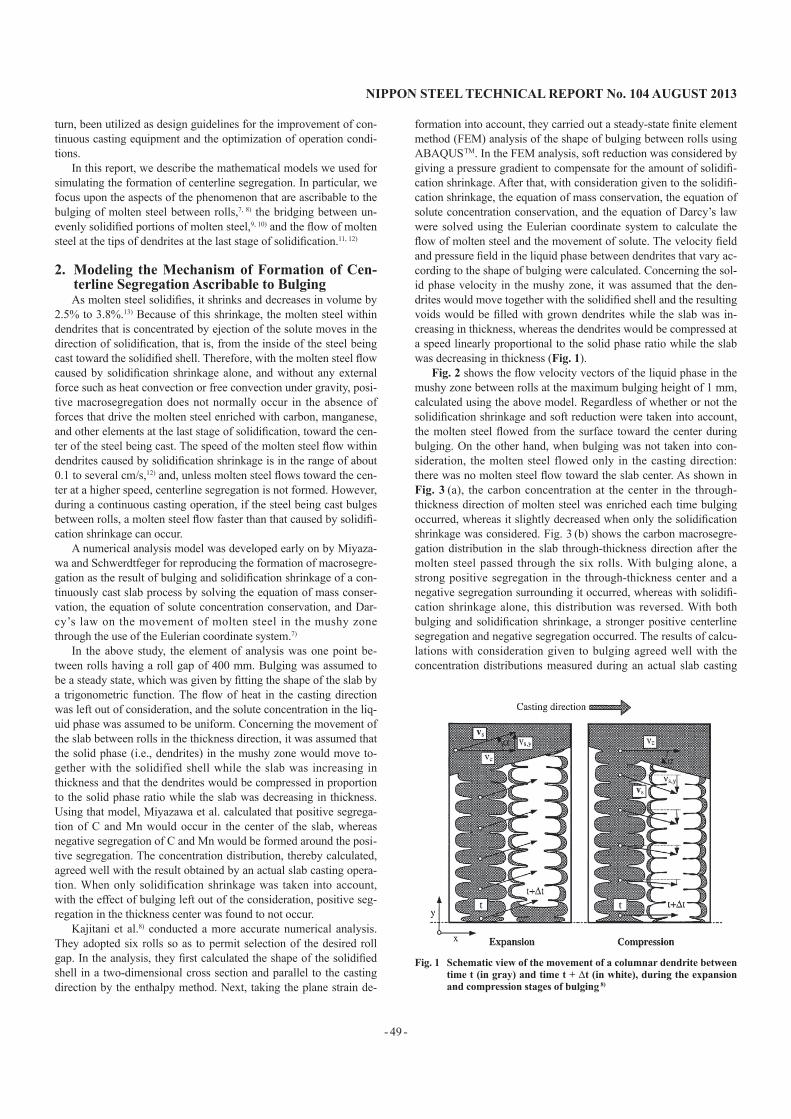
formation into account, they carried out a steady-state finite element method (FEM) analysis of the shape of bulging between rolls using ABAQUS TM. In the FEM analysis, soft reduction was considered by giving a pressure gradient to compensate for the amount of solidifi-cation shrinkage. After that, with consideration given to the solidifi-cation shrinkage, the equation of mass conservation, the equation of solute concentration conservation, and the equation of Darcy’s law were solved using the Eulerian coordinate system to calculate the flow of molten steel and the movement of solute. The velocity field and pressure field in the liquid phase between dendrites that vary ac-cording to the shape of bulging were calculated. Concerning the sol-id phase velocity in the mushy zone, it was assumed that the den-drites would move together with the solidified shell and the resulting voids would be filled with grown dendrites while the slab was in-creasing in thickness, whereas the dendrites would be compressed at a speed linearly proportional to the solid phase ratio while the slab was decreasing in thickness (Fig. 1).
Fig. 2 shows the flow velocity vectors of the liquid phase in the mushy zone between rolls at the maximum bulging height of 1 mm, calculated using the above model. Regardless of whether or not the solidification shrinkage and soft reduction were taken into account, the molten steel flowed from the surface toward the center during bulging. On the other hand, when bulging was not taken into con-sideration, the molten steel flowed only in the casting direction: there was no molten steel flow toward the slab center. As shown in Fig. 3 (a), the carbon concentration at the center in the through-thickness direction of molten steel was enriched each time bulging occurred, whereas it slightly decreased when only the solidification shrinkage was considered. Fig. 3 (b) shows the carbon macrosegre-gation distribution in the slab through-thickness direction after the molten steel passed through the six rolls. With bulging alone, a strong positive segregation in the through-thickness center and a negative segregation surrounding it occurred, whereas with solidifi-cation shrinkage alone, this distribution was reversed. With both bulging and solidification shrinkage, a stronger positive centerline segregation and negative segregation occurred. The results of calcu-lations with consideration given to bulging agreed well with the concentration distributions measured during an actual slab casting
Fig. 1 Schematic view of the movement of a columnar dendrite between time t (in gray) and time t + Δt (in white), during the expansion and compression stages of bulging 8)

NIPPON STEEL TECHNICAL REPORT No. 104 AUGUST 2013
- 50 -
operation.Fig. 4 shows the change in carbon concentration at the through-
thickness center of the slab when the amount of bulging varied. The amount of enrichment of the carbon concentration between rolls was proportional to the amount of bulging.
Fig. 5 shows the influence of soft reduction on the carbon con-centration at the through-thickness center. When the maximum amount of bulging was 0.1 mm (Fig. 5 (a)), macrosegregation was reduced by soft reduction. By contrast, when the maximum amount of bulging was 1.0 mm (Fig. 5 (b)), macrosegregation moderated during soft reduction. The reason for that was considered as follows.
Fig. 2 Relative liquid velocity field in the mushy zone: (a) maximum bulging of 1mm, no shrinkage, no soft reduction; (b) maximum bulging of 1mm, with shrinkage, no soft reduction; (c) no bulg-ing, with shrinkage, no soft reduction; (d) maximum bulging of 1mm, with shrinkage, with soft reduction 8)
Fig. 3 Influence of the solidification shrinkage on the solute distribution (a) Along the centerline and (b) Perpendicular to the centerline
after six rolls 8)
Fig. 4 Influence of the maximum bulging on the centerline segregation 8)
Fig. 5 Influence of the soft reduction on the centerline segregation cal-culated with a maximum bulging of (a) 0.1 mm and (b) 1 mm 8)

NIPPON STEEL TECHNICAL REPORT No. 104 AUGUST 2013
- 51 -
As shown in Figs. 2 (b) and (d) (molten steel flow vectors), without soft reduction, the molten steel flowed downstream from the up-stream side. With soft reduction, on the other hand, the mushy zone was compressed by the rolls, causing the segregated molten steel to move upstream from the downstream side. This interpretation is just one example. In the actual bulging phenomenon, there can be vari-ous patterns of molten steel flow depending on the variance in cra-ter-end shape. It may be said, however, that the simulation model used by Kajitani et al. suggested that there should be a certain amount of soft reduction (pressure gradient) appropriate to the amount of bulging when soft reduction is applied to stop molten steel flow at the last stage of solidification.
Computer-assisted simulations, using such models as have been described, have made it possible to predict the flow of molten steel in the mushy zone when bulging and solidification shrinkage occur. In addition, it has become possible to easily estimate or predict the effects of the roll gap, casting speed, and other parameters on the formation of centerline segregation.
3. Modeling the Mechanism of Formation of Cen-terline Segregation Ascribable to BridgingUsing a mold that was constricted in the middle, Uchimura et
al.14) let solidified shells form a bridge within the constriction in or-der to cause a delay in solidification under the bridge and let the segregated molten steel be drawn in by solidification shrinkage of the portion subject to delayed solidification, thereby producing V-segregation and centerline macrosegregation. Thus, according to the report on experimental results, even without bulging, centerline seg-regation was found to occur as a result of the bridging caused by uneven mold heat removal and solidification shrinkage. However, the factors involved in the development of macrosegregation, such as the liquid phase ratio during the movement of segregated molten steel and the routes of molten steel movement between dendrites, had not been clarified by experimentation. Besides, in the analysis using a bulging model, similar to the one described in the preceding section, the influence of solidification shrinkage on the development of macrosegregation could not be clarified sufficiently. Recently, Murao et al.9, 10) succeeded for the first time in reproducing the phe-nomenon of centerline segregation during the occurrence of bridg-ing through means of a numerical simulation using detailed models of solidification shrinkage and incorporating the changes in the physical properties of molten steel caused by solidification.
Using the commercial computer fluid dynamics (CFD) package, FLUENT TM, Murao et al. analyzed the solidification and segregation of Fe-0.1mass%C steel in a two-dimensional rectangular section 500 mm in width by 2,000 mm in height. As the driving forces for molten steel flow, they considered convection caused by a difference in pressure, which is due to solidification shrinkage, heat convec-tion, and convection caused by a difference in solute concentration, and the flow of molten steel was thereby calculated using the equa-tion of motion, the equation of continuity, the equation of energy conservation, and the equation of solute conservation. In order to calculate the solid phase ratio of the solidified shell accurately, the temperature recovery method was used with consideration given to the change in the solid phase ratio caused not only by a temperature change but also by a change in solute concentration. For the calcula-tion of segregation, the Scheil model of solidification was used. The distribution coefficient and the liquidus curve temperature were cal-culated using the thermodynamic calculation program, Thermo-CalcTM. Darcy’s law was applied to calculate the flow of molten
steel in the mushy zone. Only the side walls of the simulated rectan-gular section were cooled. The upper surface temperature was as-sumed to be the same as the molten steel temperature, and the lower surface was heat-insulated. When the solidified shell was to be bridged, the side wall temperature was set to 1,700 K at the top and 1,850 K at the bottom, with the temperatures between the top and bottom obtained by linear interpolation. When the solidified shell was not to be bridged, the wall temperature distribution was re-versed—1,850 K at the top and 1,700 K at the bottom.
Using the above model, the solute concentration distribution af-ter complete solidification was calculated. Without bridging, a minor negative segregation was formed in and around the center of the cast steel. The solute concentration distribution calculation result ob-tained when the solidified shell was bridged is shown in Fig. 6. A positive segregation was formed under the bridge, indicated by a box in Fig. 6, whereas a marked negative segregation was formed above the bridge. The calculated concentration distribution agreed well with the result obtained by a casting experiment in the labora-tory.
From the above described model, the mechanism by which posi-tive centerline segregation formed under the bridge was considered as follows.10) When bridging occurs due to uneven solidification, a region having a high solid phase ratio is formed in the center of the bridge. Under that bridge, a negative pressure distribution occurs as a result of solidification shrinkage. On the other hand, in the periph-ery of the bridge center, a region having a low solid phase ratio is formed as a result of the solute concentration. This region, having a low solid phase ratio, becomes the passage for the flow of the segre-gated molten steel, and positive centerline segregation develops as the segregated molten steel flows into the central part under the bridge.
Thus, it was suggested that centerline segregation ascribable to bridging would be formed in these four steps: ① the constriction of the liquid phase passage by formation of a region having a high sol-id phase ratio in the center and the occurrence of bridging, ② the occurrence of negative pressure under the bridge, ③ the suction of segregated molten steel from the region having a low solid phase ra-tio in the periphery of the bridge center, and ④ the formation of lin-ear and V segregates. In the former simulation model, the solid phase ratio was considered simply as a function of temperature. In
Fig. 6 Calculation of the carbon distribution in the ingot with bridging 10)

NIPPON STEEL TECHNICAL REPORT No. 104 AUGUST 2013
- 52 -
the latter model, consideration was given also to the change in solid phase ratio caused by a change in solute concentration. This made it possible to reproduce the formation of a bridge and a roundabout passage for molten steel flow in simulations. As a result, it has be-come possible to simulate the formation of V segregation and cen-terline segregation and thereby to clarify the mechanism of their formation for the first time.
4. Modeling the Mechanism of Formation of Cen-terline Segregation in Continuous Casting of BloomMany continuous-cast blooms exhibit a region of negative seg-
regation surrounding an area of positive segregation near the center-line. As an example, Fig. 7 shows the measured carbon concentra-tion distribution of a S48C bloom of medium cross-sectional area (240 mm in thickness and 263 mm in width) obtained with the No. 3 continuous caster of Muroran Works. Because of the effect of in-tense stirring by the mold electromagnetic stirrer (M-EMS), the bloom exhibited a negative segregation in the surface layer. In addi-tion, because of the effect of the negative segregation in the surface layer, a rise in carbon concentration was observed inside the nega-tive segregation region. Furthermore, the carbon concentration was found to decrease with increasing distance from the billet surface on
the upper and lower (L and F) surfaces of the bloom, in particular, on the inside from the solidification structure that changed from co-lumnar to equiaxed crystals. The decrease in carbon concentration (the formation of negative segregation) was conspicuous around the peak indicating the presence of centerline segregation.
The mechanism of formation of the described region of negative segregation surrounding an area of positive segregation near the centerline was proposed as follows. When the molten steel is solidi-fied by M-EMS while it is flowing, mass transfer from the solid-liq-uid interface within the concentration boundary layer to the bulk molten steel is promoted by turbulent mixing caused by forced con-vection, whereby the liquid-phase solute concentration in the neigh-borhood of the solid-liquid interface declines. Then, the solute con-centration of the crystallized solid phase decreases, causing negative segregation.15) It is well known that even when the molten steel is not undergoing solidification, its flow is promoted by forced con-vection along the interface in the direction perpendicular to the sol-id-liquid interface.16, 17) In light of the mechanism of formation of negative segregation by M-EMS and the effect of promotion of mass transfer in the direction perpendicular to the solid-liquid inter-face and molten steel flow by forced convection along the interface, the mechanisms by which the carbon concentration in the equiaxed crystal zone decreases and centerline segregation and negative seg-regation surrounding it occur are evaluated as follows. Fig. 8 sche-matically shows the estimated mechanism of formation of centerline segregation and the region of negative segregation around it. The formation of the actual segregation occurs in a solid–liquid phase and is not as simple as that illustrated in a scheme that assumes that the solid–liquid interface is a smooth one. For ease of understand-ing, the scheme shows the mechanism in a conceptually simplified form.
The solidification shrinkage flow toward the crater end within the solid–liquid phase promotes the mass transfer of carbon toward the center of the cross section perpendicular to the solid–liquid in-terface within the solid–liquid phase. As a result, the solute concen-tration at the liquid-phase side near the interface decreases (Ci → Ci') and the solid-phase solute concentration in the periphery of the solid–liquid phase decreases (Cs → Cs′), thereby causing a negative
Fig. 8 Simplified schematic view of formation mechanisms of V segregation, centerline segregation and negative macrosegregation near a center of cross section in a continuous cast bloom 12)
Fig. 7 Measured distribution of carbon in the bloom: S48C (0.48%C), 240mm × 263mm bloom, M-EMS on, without soft reduction 12)
NIPPON STEEL TECHNICAL REPORT No. 104 AUGUST 2013
- 53 -
segregation to be formed. In addition, as the negative segregation is formed and the solute concentration in the periphery decreases, the concentration and accumulation of solute in the remaining molten steel are promoted (CL,b → CL,b′). Thus, it can be explained that a positive segregation is formed in the center when the remaining molten steel with a concentrated solute is captured and solidified at the last stage of solidification.
The promotion of mass transfer in the direction perpendicular to the solid–liquid interface by the solidification shrinkage flow de-scribed above is considered attributable to the effect of mixing (dis-persion) of molten steel. Concerning the said effect, Fujii et al.18) an-alyzed the behavior of the mixing of molten steel from the leading and trailing ladles at a joint in slab continuous casting and estimated the mixed diffusion coefficient E within the crater. Fujii et al. esti-mated that even near the crater end, the value of E was about 20 (cm2/s), which is 104 to 105 times greater than the mutual diffusion coefficient relative to Fe, DFe-C . Assuming the representative length, L, as 20 cm, for example, E/L becomes 1 cm/s. This is not negligible even when compared with the convection velocity, 5 to 10 cm/s,12) produced by the solidification shrinkage flow. Concerning the solidi-fication shrinkage flow, too, therefore, it is considered necessary to analyze the mass transfer by applying the following basic equation of mass transfer (1) (given that E, the mixed diffusion coefficient or turbulent diffusion coefficient, ≫ Dfe-C , the molecular diffusion co-efficient) and taking mixed diffusion into account.
(1)where v is the vector molten steel flow velocity, and t is time.
5. ConclusionThe mechanism of formation of the centerline segregation has
been clarified using analytical models and simulation techniques. The knowledge about this mechanism has been utilized in the devel-opment of technology for manufacturing slabs and blooms with only minor centerline segregation and porosities. It is expected that in the future, advanced new technologies making the most effective use of computer-assisted simulations will be developed to manufacture higher-quality steel products, ultra-heavy plates, etc.
References1) Ogibayashi, S. et al.: Proc. 7th Japan-Germany Seminar on Fundamen-
tals of Iron and Steelmaking. Dusseldorf, 1987, p. 3092) Zeze, M. et al.: Tetsu-to-Hagané. 87, 77 (2001)3) Gotohda, H. et al.: CAMP-ISIJ. 5, 1341 (1992)4) Niizuma, M. et al.: 6th European Continuous Casting Conference. Dus-
seldorf, 20085) Ohnishi, Y. et al.: CAMP-ISIJ. A995 (1983)6) Zeze, M. et al.: Tetsu-to-Hagané. 87, 71 (2001)7) Miyazawa, K. et al.: Arch Eisenhuttenwes. 52, 415 (1981)8) Kajitani, T. et al.: Trans. Metall. 32A, 1479 (2001)9) Murao, T. et al.: CAMP-ISIJ. 24, 866 (2011)
10) Murao, T. et al.: CAMP-ISIJ. 25, 249 (2012)11) Isobe, K.: CAMP-ISIJ. 25, 248 (2012)12) Isobe, K.: Tetsu-to-Hagané. 98, 405 (2012)13) Yokoyama, T. et al.: Tetsu-to-Hagané. 83, 557 (1997)14) Uchimura, M. et al.: CAMP-ISIJ. 2, 1269 (1989)15) Takahashi, T. et al.: Tetsu-to-Hagané. 61, 2198 (1975)16) Isobe, K. et al.: Tetsu-to-Hagané. 76, 2033 (1990)17) Matsushita, Y. et al.: Yakin Butsuri Kagaku (Metallurgical Physicochem-
istry). Tokyo, Maruzen Publishing Co., 1970, p. 24918) Fujii, T. et al.: Tetsu-to-Hagané. 60, 1041 (1974)
Masafumi MIYAZAKIChief Researcher, Dr.Eng.Steelmaking R&D Div.Process Technology Center20-1 Shintomi, Futtsu, Chiba 293-8511
Kohichi ISOBEChief Researcher, Dr.Eng.Muroran R&D Lab.
Takemasa MURAOResearcherSteelmaking R&D Div.Process Technology Center