technical reference manual busch-smarttouch 7'' · 1473-1-9264 / 2cka001473b9264 │...
TRANSCRIPT

1473-1-9264 / 2CKA001473B9264 │ 25.08.2017
Technical Reference Manual Busch-SmartTouch®
Busch-SmartTouch® 7'' 6136/07-xxx-500
Table of contents
Technical Reference Manual 1473-1-9264 / 2CKA001473B9264 │2
Tabl e of contents
1 Notes on the instruction manual ............................................................................................................................... 11 2 Safety ........................................................................................................................................................................ 12
2.1 Information and symbols used ...................................................................................................................... 12 2.2 Intended use ................................................................................................................................................. 13 2.3 Improper use ................................................................................................................................................ 13 2.4 Target group / Qualifications of personnel .................................................................................................... 14 2.5 Safety instructions ........................................................................................................................................ 14
3 Information on protection of the environment ........................................................................................................... 15 3.1 Environment ................................................................................................................................................. 15
4 Product description ................................................................................................................................................... 16 4.1 Scope of supply ............................................................................................................................................ 17 4.2 Additional necessary components ................................................................................................................ 17 4.3 Overview of types ......................................................................................................................................... 17 4.4 Overview of KNX functions ........................................................................................................................... 17 4.5 Additional function of hearing loop ............................................................................................................... 18 4.6 Device overview ........................................................................................................................................... 18
5 Technical data ........................................................................................................................................................... 19 6 Circuit diagrams and dimensional drawings.............................................................................................................. 20
6.1 Dimensional drawings .................................................................................................................................. 20 6.2 Circuit diagrams ............................................................................................................................................ 21
7 Connection, installation / mounting ........................................................................................................................... 22 7.1 Planning instructions .................................................................................................................................... 22 7.2 Safety instructions ........................................................................................................................................ 22 7.3 Preparatory steps ......................................................................................................................................... 23 7.4 Mounting ....................................................................................................................................................... 23
7.4.1 Overview of mounting versions .................................................................................................................... 24 7.4.2 Mounting in flush-mounted installation box in hollow wall ........................................................................... 24 7.4.3 Mounting in flush-mounted installation box in solid wall .............................................................................. 25 7.4.4 Mounting with surface-mounted mounting frame......................................................................................... 26 7.4.5 Standard flush-mounted box ........................................................................................................................ 26 7.4.6 Old control panel box 6136/UP-500 (MD/U 1.1) .......................................................................................... 27 7.4.7 Table stand 83506 ....................................................................................................................................... 27 7.4.8 Swiss flush-mounted box ............................................................................................................................. 27 7.4.9 Connection and installation .......................................................................................................................... 28
7.5 Dismantling ................................................................................................................................................... 29 8 Initial commissioning ................................................................................................................................................. 30 9 Commissioning via Power-Tool ................................................................................................................................ 32
9.1 Integration into the KNX system (ETS) ......................................................................................................... 32 9.1.1 Installation of the plug-in Power-Tool for the Busch-SmartTouch® ............................................................. 32 9.1.2 Installation sequence ................................................................................................................................... 32 9.1.3 Integrating the Busch-SmartTouch® 7'' into the ETS ................................................................................... 33 9.1.4 Further KNX settings in the Busch-SmartTouch® 7'' .................................................................................... 33
9.2 Overview of the Power-Tool commissioning tool .......................................................................................... 34 9.2.1 Starting the Power-Tool ............................................................................................................................... 34
9.3 Power-Tool screen areas ............................................................................................................................. 35
Table of contents
Technical Reference Manual 1473-1-9264 / 2CKA001473B9264 │3
9.4 Explanation of the basic structure (Terms) ................................................................................................... 37 9.5 Commissioning sequence ............................................................................................................................ 38 9.6 Configuring basic settings for the panel ....................................................................................................... 38
9.6.1 Basic settings (system settings) of the panel ............................................................................................... 39 9.7 Creation of the navigation structure .............................................................................................................. 53
9.7.1 Creating operating pages (start pages) ....................................................................................................... 53 9.7.2 Creating operating pages for rooms ............................................................................................................ 53 9.7.3 Creating operating pages for floors ............................................................................................................. 54 9.7.4 Editing operating pages ............................................................................................................................... 55 9.7.5 Editing floors and rooms .............................................................................................................................. 56
9.8 Configuration of the operating pages ........................................................................................................... 58 9.8.1 "Switch" control element .............................................................................................................................. 60 9.8.2 Control element "Rocker switch".................................................................................................................. 60 9.8.3 "Dimmer" control element ............................................................................................................................ 60 9.8.4 Control element: "Dimmer slider" ................................................................................................................. 60 9.8.5 Operation of "RGBW" control element“ ....................................................................................................... 60 9.8.6 Control element: "Value slider" .................................................................................................................... 61 9.8.7 "Blind" control element ................................................................................................................................. 61 9.8.8 Control element "Fan switch" ....................................................................................................................... 61 9.8.9 "Scene" control element ............................................................................................................................... 61 9.8.10 "Display" control element ............................................................................................................................. 61 9.8.11 Control element "RTC control element" ....................................................................................................... 61 9.8.12 "Page link" control element .......................................................................................................................... 62 9.8.13 Control element "Audio control" ................................................................................................................... 62
9.9 Editing control elements ............................................................................................................................... 62 9.9.1 Delete control element ................................................................................................................................. 62 9.9.2 Copy and position control element .............................................................................................................. 63
9.10 Configuration of applications and application pages .................................................................................... 63 9.10.1 Application "Door communication" ............................................................................................................... 63 9.10.2 Application "Fault and alarm messages" ..................................................................................................... 64 9.10.3 Application "Scene actuator" ........................................................................................................................ 65 9.10.4 Application "Presence simulation" ............................................................................................................... 65 9.10.5 Application "Time programs" ........................................................................................................................ 65 9.10.6 Application "Logical functions" ..................................................................................................................... 66 9.10.7 Application "Internal RTC" ........................................................................................................................... 66
9.11 Editing communication objects ..................................................................................................................... 67 9.12 Editing group addresses ............................................................................................................................... 68 9.13 Additional tools (functions) ........................................................................................................................... 69
9.13.1 Programming (exporting) ............................................................................................................................. 69 9.13.2 Preview ........................................................................................................................................................ 69
10 Operation .................................................................................................................................................................. 70 10.1 General control and display functions .......................................................................................................... 70 10.2 Control elements .......................................................................................................................................... 72
10.2.1 Basic structures of control elements ............................................................................................................ 73 10.2.2 Additional basic principles............................................................................................................................ 74 10.2.3 Adjustable control elements ......................................................................................................................... 75
10.3 Special functions .......................................................................................................................................... 82 10.3.1 Editing .......................................................................................................................................................... 82 10.3.2 Call-up and editing of the favourites list ....................................................................................................... 83
Table of contents
Technical Reference Manual 1473-1-9264 / 2CKA001473B9264 │4
10.3.3 Access to pages ........................................................................................................................................... 84 10.3.4 Return to the previous page......................................................................................................................... 84
10.4 Operating actions of the "Door communication" application ......................................................................... 85 10.4.1 Establishing a speech and video connection ............................................................................................... 86 10.4.2 Opening the door ......................................................................................................................................... 86 10.4.3 Activating mute (mite timer) ......................................................................................................................... 87 10.4.4 Switching light .............................................................................................................................................. 87 10.4.5 Events and image storage / history ............................................................................................................. 88
10.5 Control actions of additional applications ..................................................................................................... 89 10.5.1 Presence simulation ..................................................................................................................................... 89 10.5.2 Fault and alarm messages........................................................................................................................... 91 10.5.3 Time programs ............................................................................................................................................. 94
10.6 Inserting the micro SD card (SDHC) ............................................................................................................ 98 10.7 System settings ............................................................................................................................................ 98
10.7.1 Settings for "Door communication" application .......................................................................................... 101 10.8 Setting the device for door communication ................................................................................................ 103
10.8.1 Terminal resistor ........................................................................................................................................ 103 10.8.2 Setting master/slave switches.................................................................................................................... 103
11 Addressing .............................................................................................................................................................. 104 11.1 Addressing the stations .............................................................................................................................. 104
11.1.1 Trimmer ...................................................................................................................................................... 104 11.1.2 Setting the address of the outdoor station ................................................................................................. 105 11.1.3 Assigning the doorbell push-button of an outdoor station to an apartment ............................................... 105 11.1.4 Setting the address of the indoor station ................................................................................................... 105 11.1.5 Setting of the "Standard outdoor station" ................................................................................................... 106
12 Update .................................................................................................................................................................... 110 12.1 Firmware update ......................................................................................................................................... 110 12.2 Transfer of PID file ...................................................................................................................................... 111
13 Maintenance ........................................................................................................................................................... 112 13.1 Cleaning ..................................................................................................................................................... 112
14 Control elements and application parameter .......................................................................................................... 113 14.1 "Switch" control element ............................................................................................................................. 113
14.1.1 Name of the control element ...................................................................................................................... 113 14.1.2 Function of the control element ................................................................................................................. 113 14.1.3 Size of the button ....................................................................................................................................... 113 14.1.4 Type of switch ............................................................................................................................................ 113 14.1.5 Object type 1 / value 2 ............................................................................................................................... 114 14.1.6 Status control element (icon/text) is operated via a separate object ......................................................... 117 14.1.7 Icon type .................................................................................................................................................... 117 14.1.8 Enable 1-bit communication object "Disable" ............................................................................................ 118
14.2 Control element "Rocker switch" ................................................................................................................ 119 14.2.1 Name of the control element ...................................................................................................................... 119 14.2.2 Function of the control element ................................................................................................................. 119 14.2.3 Size of the button ....................................................................................................................................... 119 14.2.4 Icon type .................................................................................................................................................... 119 14.2.5 Status control element (icon/text) is operated via a separate object ......................................................... 120 14.2.6 Object type ................................................................................................................................................. 120 14.2.7 Enable 1-bit communication object "Disable" ............................................................................................ 123
Table of contents
Technical Reference Manual 1473-1-9264 / 2CKA001473B9264 │5
14.3 "Dimmer" control element ........................................................................................................................... 124 14.3.1 Name of the control element ...................................................................................................................... 124 14.3.2 Function of the control element ................................................................................................................. 124 14.3.3 Size of the button ....................................................................................................................................... 124 14.3.4 Icon type .................................................................................................................................................... 124 14.3.5 Icon for On / icon for Off............................................................................................................................. 124 14.3.6 Position for dim up icon .............................................................................................................................. 125 14.3.7 Icon for dim up / icon for dim down ............................................................................................................ 125 14.3.8 Status control element (icon) is operated via a separate object ................................................................ 125 14.3.9 Status of dimming value is controlled by a separate object ....................................................................... 125 14.3.10 Manner of dimming .................................................................................................................................... 126 14.3.11 Enable 1-bit communication object "Disable" ............................................................................................ 127
14.4 Control element: "Dimmer slider" ............................................................................................................... 128 14.4.1 Name of the control element ...................................................................................................................... 128 14.4.2 Function of the control element ................................................................................................................. 128 14.4.3 Size of the button ....................................................................................................................................... 128 14.4.4 Icon type .................................................................................................................................................... 128 14.4.5 Icon for On / icon for Off............................................................................................................................. 128 14.4.6 Slider from .................................................................................................................................................. 129 14.4.7 Status control element (icon) is operated via a separate object ................................................................ 129 14.4.8 Display value in control element ................................................................................................................ 129 14.4.9 Slider sends ............................................................................................................................................... 130 14.4.10 Brightness change [%] ............................................................................................................................... 130 14.4.11 Enable 1-bit communication object "Disable" ............................................................................................ 130
14.5 Operation of "RGBW" control element“ ...................................................................................................... 131 14.5.1 Name of the control element ...................................................................................................................... 131 14.5.2 Function of the control element ................................................................................................................. 131 14.5.3 Display value in control element ................................................................................................................ 131 14.5.4 Type of colour/white lamp .......................................................................................................................... 131 14.5.5 Brightness change [%] ............................................................................................................................... 134 14.5.6 Telegram is repeated every [sec.]: ............................................................................................................ 134 14.5.7 Enable 1-bit communication object "Disable" ............................................................................................ 134
14.6 Control element: "Value slider" ................................................................................................................... 135 14.6.1 Name of the control element ...................................................................................................................... 135 14.6.2 Function of the control element ................................................................................................................. 135 14.6.3 Size of the button ....................................................................................................................................... 135 14.6.4 Slider from .................................................................................................................................................. 135 14.6.5 Display value in control element ................................................................................................................ 136 14.6.6 Slider sends ............................................................................................................................................... 136 14.6.7 Object type ................................................................................................................................................. 137 14.6.8 Enable 1-bit communication object "Disable" ............................................................................................ 138
14.7 "Blind" control element ............................................................................................................................... 139 14.7.1 Name of the control element ...................................................................................................................... 139 14.7.2 Function of the control element ................................................................................................................. 139 14.7.3 Size of the button ....................................................................................................................................... 139 14.7.4 Type of control ........................................................................................................................................... 139 14.7.5 Icon type .................................................................................................................................................... 140 14.7.6 Status control element (icon) is operated via a separate object ................................................................ 141 14.7.7 Enable 1-bit communication object "Disable" ............................................................................................ 141
14.8 Control element "Fan switch" ..................................................................................................................... 142
Table of contents
Technical Reference Manual 1473-1-9264 / 2CKA001473B9264 │6
14.8.1 Name of the control element ...................................................................................................................... 142 14.8.2 Function of the control element ................................................................................................................. 142 14.8.3 Size of the button ....................................................................................................................................... 142 14.8.4 Deactivation of switch-off option ................................................................................................................ 142 14.8.5 Icon type .................................................................................................................................................... 143 14.8.6 Telegram is repeated every [sec.]: ............................................................................................................ 143 14.8.7 Number of speed levels ............................................................................................................................. 144 14.8.8 Object type ................................................................................................................................................. 144 14.8.9 Display status ............................................................................................................................................. 145 14.8.10 Enable 1-bit communication object "Disable" ............................................................................................ 146
14.9 "Scene" control element ............................................................................................................................. 147 14.9.1 Name of the control element ...................................................................................................................... 147 14.9.2 Function of the control element ................................................................................................................. 147 14.9.3 Start scene at selection .............................................................................................................................. 147 14.9.4 Long operation after... ................................................................................................................................ 147 14.9.5 Number of scenes [1 - 10].......................................................................................................................... 147 14.9.6 Scene number x [1 - 64]............................................................................................................................. 148 14.9.7 Name of scene x ........................................................................................................................................ 148 14.9.8 Saving scene x with a long press .............................................................................................................. 148 14.9.9 Enable 1-bit communication object "Disable" ............................................................................................ 148
14.10 "Display" control element ............................................................................................................................ 149 14.10.1 Name of the control element ...................................................................................................................... 149 14.10.2 Function of the control element ................................................................................................................. 149 14.10.3 Type of display element ............................................................................................................................. 149 14.10.4 Type of display element — Status display — Size of the button ............................................................... 150 14.10.5 Type of display element — Status display — Object type ......................................................................... 150 14.10.6 Type of display element — Value display — Size of the button ................................................................ 151 14.10.7 Type of display element — Value display — Object type .......................................................................... 151 14.10.8 Type of display element — Linear measurement display — Measurement display with colour
display ........................................................................................................................................................ 153 14.10.9 Type of display element — Linear measurement display — Display value in control element ................. 153 14.10.10 Type of display element — Linear measurement display — Object type .................................................. 154 14.10.11 Type of display element — Round measurement display ......................................................................... 155 14.10.12 Type of display element — Wind rose ....................................................................................................... 155 14.10.13 Type of display element — Wind force — Size of the button .................................................................... 155 14.10.14 Type of display element — Wind force — Unit .......................................................................................... 156 14.10.15 Type of display element — Temperature — Size of the button ................................................................. 156 14.10.16 Type of display element — Temperature — Unit....................................................................................... 156 14.10.17 Type of display element — Rain — Size of the button .............................................................................. 156 14.10.18 Type of display element — Rain — Text for rain ....................................................................................... 156 14.10.19 Type of display element — Rain — Text for no rain .................................................................................. 156 14.10.20 Type of display element — Twilight — Size of the button ......................................................................... 157 14.10.21 Type of display element — Twilight — Unit ............................................................................................... 157 14.10.22 Type of display element — Brightness ...................................................................................................... 157 14.10.23 Type of display element — CO2 — Size of the button ............................................................................... 157 14.10.24 Type of display element — CO2 — Unit .................................................................................................... 157 14.10.25 Type of display element — Moisture — Size of the button ........................................................................ 157 14.10.26 Type of display element — Moisture — Unit ............................................................................................. 158 14.10.27 Type of display element — Air pressure — Size of the button .................................................................. 158 14.10.28 Type of display element — Air pressure — Unit ........................................................................................ 158 14.10.29 Enable 1-bit communication object "Disable" ............................................................................................ 158
14.11 Control element "RTC control element" ...................................................................................................... 159
Table of contents
Technical Reference Manual 1473-1-9264 / 2CKA001473B9264 │7
14.11.1 Name of the control element ...................................................................................................................... 159 14.11.2 Function of the control element ................................................................................................................. 159 14.11.3 Additional functions/objects ....................................................................................................................... 159 14.11.4 Delay time during reading of telegrams after reset [sec.] .......................................................................... 159 14.11.5 Input for temperature reading .................................................................................................................... 160 14.11.6 Display actual temperature ........................................................................................................................ 160 14.11.7 Temperature unit ........................................................................................................................................ 160 14.11.8 Set value is relative .................................................................................................................................... 161 14.11.9 Heating/cooling switchover ........................................................................................................................ 161 14.11.10 Fan coil control during heating mode ......................................................................................................... 161 14.11.11 Fan coil control during cooling mode ......................................................................................................... 161 14.11.12 Setting the temperature unit via object ...................................................................................................... 161 14.11.13 Enable 1-bit communication object "Disable" ............................................................................................ 161
14.12 "Page link" control element ......................................................................................................................... 162 14.12.1 Name of the control element ...................................................................................................................... 162 14.12.2 Function of the control element ................................................................................................................. 162 14.12.3 Size of the button ....................................................................................................................................... 162 14.12.4 Linked with page ........................................................................................................................................ 162 14.12.5 Enable 1-bit communication object "Disable" ............................................................................................ 163
14.13 Control element "Audio control" .................................................................................................................. 164 14.13.1 Name of the control element ...................................................................................................................... 164 14.13.2 Function of the control element ................................................................................................................. 164 14.13.3 Number of sources ..................................................................................................................................... 164 14.13.4 Use of play button ...................................................................................................................................... 165 14.13.5 Use of pause button ................................................................................................................................... 165 14.13.6 Use of stop button ...................................................................................................................................... 166 14.13.7 Use of forward button ................................................................................................................................. 167 14.13.8 Use of return key ........................................................................................................................................ 167 14.13.9 Use of key for mute .................................................................................................................................... 168 14.13.10 Use of volume key ..................................................................................................................................... 169 14.13.11 Use of ON/OFF key ................................................................................................................................... 170 14.13.12 Enable 1-bit communication object "Disable" ............................................................................................ 170
14.14 Application "Door communication" ............................................................................................................. 171 14.14.1 Use of door communication ....................................................................................................................... 171 14.14.2 Page PIN-protected ................................................................................................................................... 171 14.14.3 Ring tone volume preset [%] ...................................................................................................................... 171 14.14.4 Speech volume preset [%] ......................................................................................................................... 171
14.15 Application "Fault and alarm messages" - Global settings ......................................................................... 172 14.15.1 Use of fault and alarm messages .............................................................................................................. 172 14.15.2 Page PIN-protected ................................................................................................................................... 172 14.15.3 Enable export ............................................................................................................................................. 172 14.15.4 Automatic archive at an acknowledge ....................................................................................................... 173 14.15.5 Sound for alarm ......................................................................................................................................... 173 14.15.6 Sound for hint ............................................................................................................................................. 173 14.15.7 Signal tone for error ................................................................................................................................... 173 14.15.8 Default setting for signal tone volume [%] ................................................................................................. 173
14.16 Application "Fault and alarm messages" - Settings of the individual messages ........................................ 174 14.16.1 Name of message ...................................................................................................................................... 174 14.16.2 Type of message ....................................................................................................................................... 174 14.16.3 Type of alarm ............................................................................................................................................. 174
14.17 Application "Scene actuator" ...................................................................................................................... 176

Table of contents
Technical Reference Manual 1473-1-9264 / 2CKA001473B9264 │8
14.17.1 Name of scene actuator ............................................................................................................................. 176 14.17.2 Number of participants ............................................................................................................................... 176 14.17.3 Number of scenes ...................................................................................................................................... 176 14.17.4 Overwriting scenes during download ......................................................................................................... 176 14.17.5 Telegram delay .......................................................................................................................................... 176 14.17.6 Object type x .............................................................................................................................................. 177 14.17.7 Name of scene ........................................................................................................................................... 179 14.17.8 Scene number ............................................................................................................................................ 179 14.17.9 Light scenes can be started with ............................................................................................................... 179 14.17.10 Light scene can be stored .......................................................................................................................... 179 14.17.11 Object x is to be changed .......................................................................................................................... 179
14.18 Application "Presence simulation" .............................................................................................................. 180 14.18.1 Use of presence simulation........................................................................................................................ 180 14.18.2 Page PIN-protected ................................................................................................................................... 180 14.18.3 Enable export ............................................................................................................................................. 181 14.18.4 Delay time up to activation [min.] ............................................................................................................... 181 14.18.5 Object type 1-20 ......................................................................................................................................... 181
14.19 Application "Time programs" ...................................................................................................................... 182 14.19.1 Page PIN-protected ................................................................................................................................... 182 14.19.2 Overwriting time programs during download ............................................................................................. 182
14.20 Application "Logical functions" .................................................................................................................... 183 14.20.1 Channel x — Application............................................................................................................................ 183
14.21 Application "Internal RTC" .......................................................................................................................... 194 14.21.1 General - Device function .......................................................................................................................... 194 14.21.2 General - Control function .......................................................................................................................... 194 14.21.3 General - Operating mode after reset ........................................................................................................ 195 14.21.4 General - Send cyclic "In operation" (min) ................................................................................................. 196 14.21.5 General - Additional functions .................................................................................................................... 196 14.21.6 General — Delay time for read telegrams after reset [s] ........................................................................... 196 14.21.7 Heating control - Control value type .......................................................................................................... 197 14.21.8 Heating control - Heating type ................................................................................................................... 198 14.21.9 Heating control - P-component (x 0.1°C) .................................................................................................. 198 14.21.10 Heating control - I-component (min.) ......................................................................................................... 199 14.21.11 Heating control — Extended settings ........................................................................................................ 199 14.21.12 Basic stage heating .................................................................................................................................... 199 14.21.13 Basic stage heating - Status object heating............................................................................................... 199 14.21.14 Basic stage heating - Mode of the control value ........................................................................................ 199 14.21.15 Basic stage heating - Hysteresis (x 0.1°C) ................................................................................................ 200 14.21.16 Basic stage heating - Control value difference for sending of heating control value ................................. 200 14.21.17 Basic stage heating - Cyclic sending of the control value (min) ................................................................ 200 14.21.18 Basic stage heating - PWM cycle heating (min) ........................................................................................ 201 14.21.19 Basic stage heating - Maximum control value (0 - 255) ............................................................................ 201 14.21.20 Basic stage heating - Minimum control value for basic load (0 to 255) ..................................................... 201 14.21.21 Settings of basic load - Minimum control value for basic load > 0 ............................................................. 202 14.21.22 Basic load settings — Basic load active when controller is off .................................................................. 202 14.21.23 Setpoint settings - Setpoint temperature for heating comfort (°C) ............................................................ 203 14.21.24 Setpoint settings - Reduction for standby heating (°C) ............................................................................. 203 14.21.25 Setpoint settings - Reduction for ECO heating (°C) .................................................................................. 203 14.21.26 Setpoint settings - Set-point temperature for frost protection (°C) ............................................................ 204 14.21.27 Setpoint settings - Send current setpoint ................................................................................................... 204 14.21.28 Setpoint settings - Cyclic sending of the current set-point temperature (min) ........................................... 204

Table of contents
Technical Reference Manual 1473-1-9264 / 2CKA001473B9264 │9
14.21.29 Setpoint adjustment — Maximum manual increase during heating mode (0 - 9°C) ................................. 204 14.21.30 Setpoint adjustment — Maximum manual reduction during heating mode (0 - 9°C) ................................ 205 14.21.31 Setpoint adjustment - Resetting of the manual adjustment for receipt of a basic setpoint ........................ 205 14.21.32 Setpoint adjustment - Resetting the manual adjustment for change of operating mode ........................... 205 14.21.33 Setpoint adjustment - Resetting the manual adjustment via object ........................................................... 206 14.21.34 Setpoint adjustment - Permanent storage of on-site operation ................................................................. 206 14.21.35 Temperature reading - Inputs of temperature reading ............................................................................... 206 14.21.36 Temperature reading - Inputs of weighted temperature reading ............................................................... 206 14.21.37 Temperature reading — Weighting of internal measurement (0 to 100%) ................................................ 207 14.21.38 Temperature reading — Weighting of external measurement (0 to 100%) ............................................... 207 14.21.39 Temperature reading — Weighting of external measurement 2 (0 to 100%) ............................................ 207 14.21.40 Temperature reading - Cyclic sending of the actual temperature (min) .................................................... 207 14.21.41 Temperature reading — Difference of value for sending the actual temperature (x 0.1°C) ...................... 208 14.21.42 Temperature reading - Adjustment value for internal temperature measurement (x 0.1°C) ..................... 208 14.21.43 Temperature reading - Monitoring time for temperature reading (0 = no monitoring) (min) ...................... 208 14.21.44 Temperature reading - Control value for fault (0 - 255) ............................................................................. 208 14.21.45 Alarm functions - Frost alarm temperature for HVAC and RHCC status (°C) ........................................... 209 14.21.46 Alarm functions - Heat alarm temperature for RHCC status (°C) .............................................................. 209 14.21.47 Control of additional heating stage - Temperature difference to basic stage (x 0.1°C) ............................ 209 14.21.48 Control of additional heating stage - Additional heating type .................................................................... 210 14.21.49 Control of additional heating stage - P-component (x 0.1°C) .................................................................... 210 14.21.50 Control of additional heating stage - I-component (min) ............................................................................ 211 14.21.51 Cooling control - Cooling type .................................................................................................................... 211 14.21.52 Cooling control - P-component (x 0.1°C) ................................................................................................... 212 14.21.53 Cooling control - I-component (min.) ......................................................................................................... 212 14.21.54 Cooling control - Extended settings ........................................................................................................... 212 14.21.55 Basic stage cooling .................................................................................................................................... 213 14.21.56 Basic stage cooling - Status object cooling ............................................................................................... 213 14.21.57 Basic stage cooling - Mode of the control value ........................................................................................ 213 14.21.58 Basic stage cooling - Hysteresis (x 0.1°C) ................................................................................................ 214 14.21.59 Basic stage cooling - Cyclic sending of the control value (min) ................................................................. 214 14.21.60 Basic stage cooling - PWM cycle cooling (min) ......................................................................................... 215 14.21.61 Basic stage cooling - Maximum control value (0 - 255) ............................................................................. 215 14.21.62 Basic stage cooling - Minimum control value for basic load (0 to 255) ...................................................... 215 14.21.63 Settings of basic load - Minimum control value for basic load > 0 ............................................................. 216 14.21.64 Basic load settings — Basic load active when controller is off .................................................................. 216 14.21.65 Setpoint settings - Setpoint temperature for cooling comfort (°C) ............................................................. 217 14.21.66 Setpoint settings - Increase for standby cooling (°C) ................................................................................ 217 14.21.67 Setpoint settings - Increase for ECO cooling (°C) ..................................................................................... 217 14.21.68 Setpoint settings - Set-point temperature for heat protection (°C) ............................................................ 218 14.21.69 Setpoint settings - Send current setpoint ................................................................................................... 218 14.21.70 Setpoint settings - Cyclic sending of the current set-point temperature (min) ........................................... 218 14.21.71 Setpoint adjustment — Maximum manual increase during cooling mode (0 - 9°C) .................................. 218 14.21.72 Setpoint adjustment — Maximum manual reduction during cooling mode (0 - 9°C) ................................ 219 14.21.73 Setpoint adjustment - Resetting of the manual adjustment for receipt of a basic setpoint ........................ 219 14.21.74 Setpoint adjustment - Resetting the manual adjustment for change of operating mode ........................... 219 14.21.75 Setpoint adjustment - Resetting the manual adjustment via object ........................................................... 220 14.21.76 Setpoint adjustment - Permanent storage of on-site operation ................................................................. 220 14.21.77 Setpoint adjustment - Permanent storage of on-site operation ................................................................. 220 14.21.78 Temperature reading - Inputs of temperature reading ............................................................................... 220 14.21.79 Temperature reading - Inputs of weighted temperature reading ............................................................... 221 14.21.80 Temperature reading — Weighting of internal measurement (0 to 100%) ................................................ 221
Table of contents
Technical Reference Manual 1473-1-9264 / 2CKA001473B9264 │10
14.21.81 Temperature reading — Weighting of external measurement (0 to 100%) ............................................... 221 14.21.82 Temperature reading — Weighting of external measurement 2 (0 to 100%) ............................................ 221 14.21.83 Temperature reading - Cyclic sending of the actual temperature (min) .................................................... 222 14.21.84 Temperature reading — Difference of value for sending the actual temperature (x 0.1°C) ...................... 222 14.21.85 Temperature reading - Adjustment value for internal temperature measurement (x 0.1°C) ..................... 222 14.21.86 Temperature reading - Monitoring time for temperature reading (0 = no monitoring) (min) ...................... 223 14.21.87 Temperature reading - Control value for fault (0 - 255) ............................................................................. 223 14.21.88 Alarm functions - Condensate water alarm ................................................................................................ 223 14.21.89 Alarm functions — Dew point alarm .......................................................................................................... 224 14.21.90 Alarm functions - Frost alarm temperature for HVAC and RHCC status (°C) ........................................... 224 14.21.91 Alarm functions - Heat alarm temperature for RHCC status (°C) .............................................................. 224 14.21.92 Summer compensation .............................................................................................................................. 224 14.21.93 Summer compensation - Summer compensation...................................................................................... 225 14.21.94 Summer compensation - (Lower) Starting temperature for summer compensation (°C) .......................... 226 14.21.95 Summer compensation - Offset of the set-point temperature for the entry into summer
compensation (x 0.1°C) ............................................................................................................................. 226 14.21.96 Summer compensation - (Upper) exit temperature for summer compensation (°C) ................................. 226 14.21.97 Summer compensation - Offset of the set-point temperature for the exit from summer compensation
(x 0.1°C)..................................................................................................................................................... 227 14.21.98 Control of additional cooling stage - Cooling type ..................................................................................... 228 14.21.99 Control of additional cooling stage - P-component (x 0.1°C) .................................................................... 228 14.21.100 Control of additional cooling stage - P-component (min) ........................................................................... 229 14.21.101 Combined heating and cooling modes ...................................................................................................... 229 14.21.102 Combined heating and cooling modes - Switchover of heating/cooling .................................................... 229 14.21.103 Combined heating and cooling modes - Operating mode after reset ........................................................ 230 14.21.104 Combined heating and cooling modes - Heating/cooling control value output .......................................... 230 14.21.105 Setpoint settings - Setpoint for heating comfort = setpoint for cooling comfort ......................................... 230 14.21.106 Setpoint settings - Hysteresis for switchover heating/cooling (x 0.1°C) .................................................... 231 14.21.107 Setpoint settings - Setpoint temperature for heating and cooling comfort (°C) ......................................... 231 14.21.108 Temperature reading — Operating mode for fault ..................................................................................... 231 14.21.109 Combined heating and cooling modes - Additional heating/cooling stage control value output................ 232
15 Notes ....................................................................................................................................................................... 233 16 Index ....................................................................................................................................................................... 234
Notes on the instruction manual
Technical Reference Manual 1473-1-9264 / 2CKA001473B9264 │11
1 Notes on the instruction manual
Please read through this manual carefully and observe the information it contains. This will assist you in preventing injuries and damage to property, and ensure both reliable operation and a long service life for the device.
Please keep this manual in a safe place.
If you pass the device on, also pass on this manual along with it.
ABB accepts no liability for any failure to observe the instructions in this manual.
If you require additional information or have questions about the device, please contact ABB or visit our Internet site at:
www.BUSCH-JAEGER.com
Note Notes on planning and application for ABB-Welcome systems are available in the system manual for ABB-Welcome. This can be downloaded at www.BUSCH-JAEGER.com.
Safety
Technical Reference Manual 1473-1-9264 / 2CKA001473B9264 │12
2 Safety
The device has been constructed according to the latest valid regulations governing technology and is operationally reliable. It has been tested and left the factory in a technically safe and reliable state.
However, residual hazards remain. Read and adhere to the safety instructions to prevent hazards of this kind.
ABB accepts no liability for any failure to observe the safety instructions.
2.1 Information and symbols used
The following Instructions point to particular hazards involved in the use of the device or provide practical instructions:
Danger Risk of death / serious damage to health – The respective warning symbol in connection with the signal word "Danger"
indicates an imminently threatening danger which leads to death or serious (irreversible) injuries.
Warning Serious damage to health – The respective warning symbol in connection with the signal word "Warning"
indicates a threatening danger which can lead to death or serious (irreversible) injuries.
Caution Damage to health – The respective warning symbol in connection with the signal word "Caution"
indicates a danger which can lead to minor (reversible) injuries.
Attention Damage to property – This symbol in connection with the signal word "Attention" indicates a
situation which could cause damage to the product itself or to objects in its surroundings.
NOTE This symbol in connection with the word "Note" indicates useful tips and recommendations for the efficient handling of the product.
This symbol alerts to electric voltage.

Safety
Technical Reference Manual 1473-1-9264 / 2CKA001473B9264 │13
2.2 Intended use
The Busch-SmartTouch® 7'' is a KNX touch panel which can be freely programmed. The device serves as a comprehensive control and message unit for the entire KNX installation. The touch panel can be used as terminal device (indoor video station) for communication with the ABB-Welcome outdoor stations. As part of the ABB-Welcome door communication system is operates exclusively with the components of this system.
The device is intended for the following: ■ Operation according to the listed technical data ■ Installation in dry interior rooms ■ Use with the connecting options available on the device
The intended use also includes adherence to all specifications in this manual.
2.3 Improper use
Each use not listed in Chapter 2.2 “Intended use“ on page 13 is deemed improper use and can lead to personal injury and damage to property.
ABB is not liable for damages caused by use deemed contrary to the intended use of the device. The associated risk is borne exclusively by the user/operator.
The device is not intended for the following: ■ Unauthorized structural changes ■ Repairs ■ Outdoor use ■ The use in bathroom areas ■ Insert with an additional bus coupler
Safety
Technical Reference Manual 1473-1-9264 / 2CKA001473B9264 │14
2.4 Target group / Qualifications of personnel
Installation, commissioning and maintenance of the device must only be carried out by trained and properly qualified electrical installers.
The electrical installer must have read and understood the manual and follow the instructions provided.
The electrical installer must adhere to the valid national regulations in his/her country governing the installation, functional test, repair and maintenance of electrical products.
The electrical installer must be familiar with and correctly apply the "five safety rules" (DIN VDE 0105, EN 50110):
1. Disconnect 2. Secure against being re-connected 3. Ensure there is no voltage 4. Connect to earth and short-circuit 5. Cover or barricade adjacent live parts
2.5 Safety instructions
Danger - Electric voltage! Electric voltage! Risk of death and fire due to electric voltage of 100 … 240 V. Dangerous currents flow through the body when coming into direct or indirect contact with live components. This can result in electric shock, burns or even death. ■ Work on the 100 … 240 V supply system may only be performed by
authorised and qualified electricians. ■ Disconnect the mains power supply before installation / disassembly. ■ Never use the device with damaged connecting cables. ■ Do not open covers firmly bolted to the housing of the device. ■ Use the device only in a technically faultless state. ■ Do not make changes to or perform repairs on the device, on its components
or its accessories. ■ Keep the device away from water and wet surroundings.
Caution! - Risk of damaging the device due to external factors! Moisture and contamination can damage the device. ■ Protect the device against humidity, dirt and damage during transport,
storage and operation.
Information on protection of the environment
Technical Reference Manual 1473-1-9264 / 2CKA001473B9264 │15
3 Information on protection of the environment
3.1 Environment
Consider the protection of the environment! Used electric and electronic devices must not be disposed of with domestic waste. – The device contains valuable raw materials which can be recycled.
Therefore, dispose of the device at the appropriate collecting depot.
All packaging materials and devices bear the markings and test seals for proper disposal. Always dispose of the packaging material and electric devices and their components via the authorized collecting depots and disposal companies.
The products meet the legal requirements, in particular the laws governing electronic and electrical devices and the REACH ordinance.
(EU Directive 2012/19/EU WEEE and 2011/65/EU RoHS)
(EU REACH ordinance and law for the implementation of the ordinance (EC) No.1907/2006).
Product description
Technical Reference Manual 1473-1-9264 / 2CKA001473B9264 │16
4 Product description
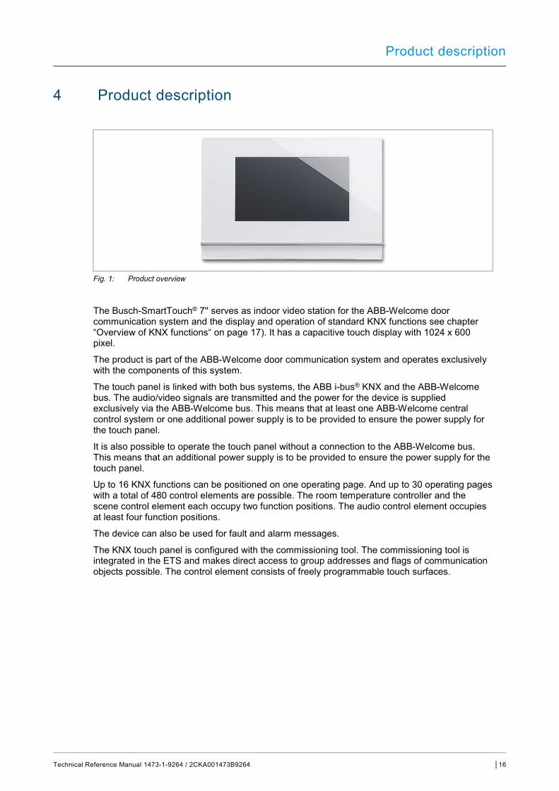
Fig. 1: Product overview
The Busch-SmartTouch® 7'' serves as indoor video station for the ABB-Welcome door communication system and the display and operation of standard KNX functions see chapter “Overview of KNX functions“ on page 17). It has a capacitive touch display with 1024 x 600 pixel.
The product is part of the ABB-Welcome door communication system and operates exclusively with the components of this system.
The touch panel is linked with both bus systems, the ABB i-bus® KNX and the ABB-Welcome bus. The audio/video signals are transmitted and the power for the device is supplied exclusively via the ABB-Welcome bus. This means that at least one ABB-Welcome central control system or one additional power supply is to be provided to ensure the power supply for the touch panel.
It is also possible to operate the touch panel without a connection to the ABB-Welcome bus. This means that an additional power supply is to be provided to ensure the power supply for the touch panel.
Up to 16 KNX functions can be positioned on one operating page. And up to 30 operating pages with a total of 480 control elements are possible. The room temperature controller and the scene control element each occupy two function positions. The audio control element occupies at least four function positions.
The device can also be used for fault and alarm messages.
The KNX touch panel is configured with the commissioning tool. The commissioning tool is integrated in the ETS and makes direct access to group addresses and flags of communication objects possible. The control element consists of freely programmable touch surfaces.

Product description
Technical Reference Manual 1473-1-9264 / 2CKA001473B9264 │17
4.1 Scope of supply
The panel is included in the scope of supply. It further includes a micro SD card (SDHC) with adapter, e.g. for the slot of a PC.
The enclosed bus connection terminal serves for the connection with the ABB i-bus® KNX and/or the ABB-Welcome bus.
The special Surface-mounted mounting frame (6136/27-xxx-500) and the associated Flush-mounted installation box (6136/07 UP-500; windproof) are not included in the scope of supply.
The necessary power adapters (e.g. 6358-101) are also not included in the scope of supply.
4.2 Additional necessary components
■ Power adapter for the 20 - 32 V DC (SELV) auxiliary power supply (power supply of device) or the central control system ABB-Welcome (no additional power supply is necessary in this case).
■ Associated flush-mounted installation box or surface-mounted mounting frame (if the device is not mounted on the associated flush-mounted installation box).
4.3 Overview of types
Article no. Product name Colour Display diagonal
6136/07-811-500 Busch-SmartTouch® 7'' White 17.8 cm (7“)
6136/07-825-500 Busch-SmartTouch® 7'' Black 17.8 cm (7“)
Table 1: Overview of types
4.4 Overview of KNX functions
The following table provides an overview of the possible functions and applications of the device:
Standard KNX functions Applications
■ Switching ■ Dimming ■ Slide controller functions ■ Blind control ■ RGBW operation ■ Fan control (step switching) ■ Scene control ■ Display functions (display elements) ■ Room temperature controller (RTC) ■ Page link functions ■ Audio control
■ Door communication ■ Fault and alarm messages ■ Scene actuator ■ Presence simulation ■ Time programs ■ Logical functions ■ Internal RTC
Table 2: Overview of functions

Product description
Technical Reference Manual 1473-1-9264 / 2CKA001473B9264 │18
4.5 Additional function of hearing loop
The device is equipped with a hearing loop for coupling the audio signals with hearing aids.
To be able to use such hearing loops, the hearing aid must have a so-called telephone coil ("T-coil" for short), which takes up the magnetic alternating field of the hearing loop. Normally the microphone of the hearing aid is deactivated when the telephone coil is in use.
The maximum distance to the device for optimum reception should be 80 cm.
4.6 Device overview
Fig. 2: Overview of device Busch-SmartTouch® 7''
[1] Front of device [2] Touch-sensitive user interface [3] Slot for micro SD card (SDHC)
Technical data
Technical Reference Manual 1473-1-9264 / 2CKA001473B9264 │19
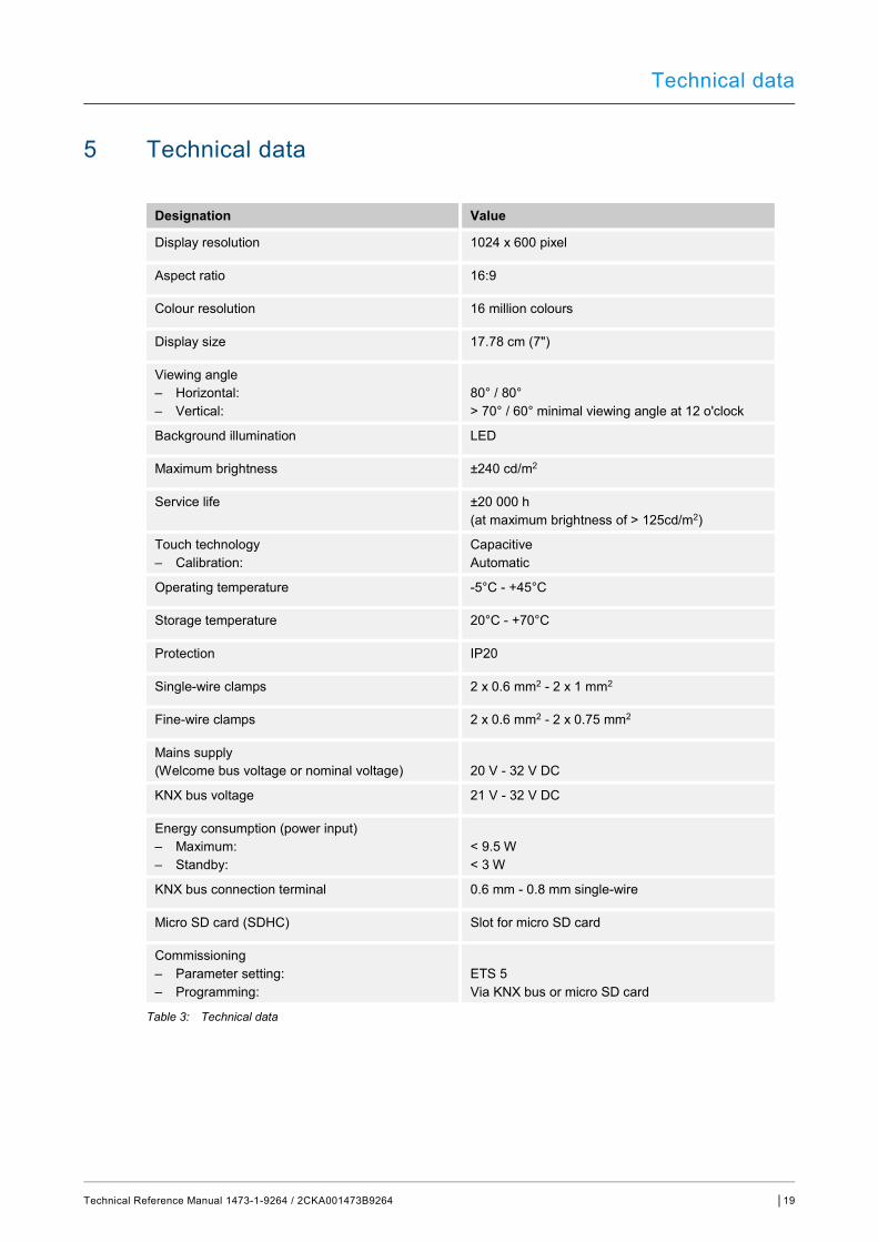
5 Technical data
Designation Value
Display resolution 1024 x 600 pixel
Aspect ratio 16:9
Colour resolution 16 million colours
Display size 17.78 cm (7")
Viewing angle – Horizontal: – Vertical:
80° / 80° > 70° / 60° minimal viewing angle at 12 o'clock
Background illumination LED
Maximum brightness ±240 cd/m2
Service life ±20 000 h (at maximum brightness of > 125cd/m2)
Touch technology – Calibration:
Capacitive Automatic
Operating temperature -5°C - +45°C
Storage temperature 20°C - +70°C
Protection IP20
Single-wire clamps 2 x 0.6 mm2 - 2 x 1 mm2
Fine-wire clamps 2 x 0.6 mm2 - 2 x 0.75 mm2
Mains supply (Welcome bus voltage or nominal voltage)
20 V - 32 V DC
KNX bus voltage 21 V - 32 V DC
Energy consumption (power input) – Maximum: – Standby:
< 9.5 W < 3 W
KNX bus connection terminal 0.6 mm - 0.8 mm single-wire
Micro SD card (SDHC) Slot for micro SD card
Commissioning – Parameter setting: – Programming:
ETS 5 Via KNX bus or micro SD card
Table 3: Technical data
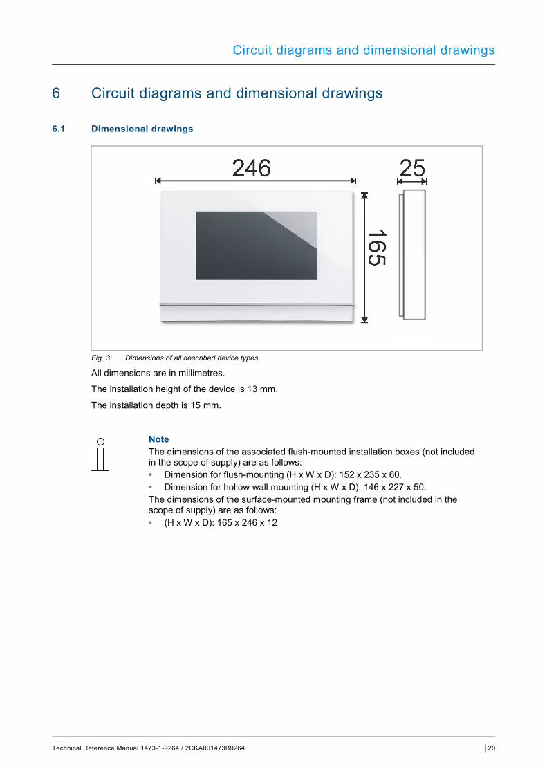
Circuit diagrams and dimensional drawings
Technical Reference Manual 1473-1-9264 / 2CKA001473B9264 │20
6 Circuit diagrams and dimensional drawings
6.1 Dimensional drawings
Fig. 3: Dimensions of all described device types
All dimensions are in millimetres.
The installation height of the device is 13 mm.
The installation depth is 15 mm.
Note The dimensions of the associated flush-mounted installation boxes (not included in the scope of supply) are as follows: ■ Dimension for flush-mounting (H x W x D): 152 x 235 x 60. ■ Dimension for hollow wall mounting (H x W x D): 146 x 227 x 50. The dimensions of the surface-mounted mounting frame (not included in the scope of supply) are as follows: ■ (H x W x D): 165 x 246 x 12
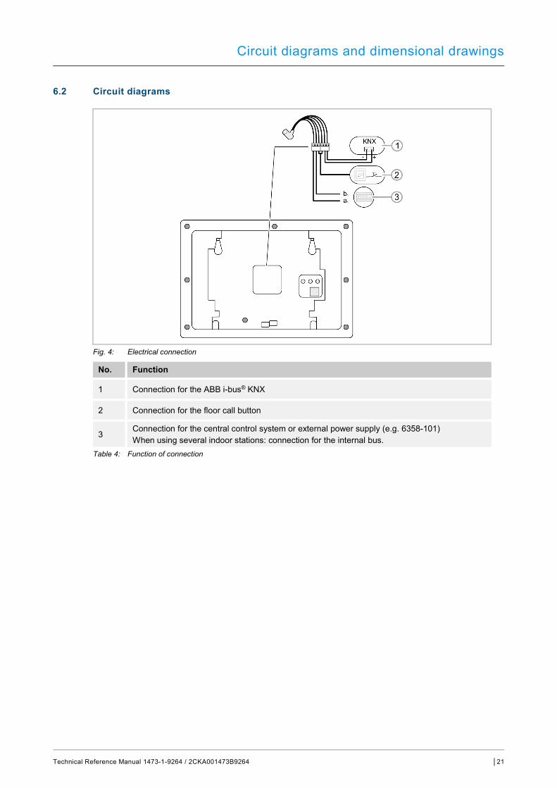
Circuit diagrams and dimensional drawings
Technical Reference Manual 1473-1-9264 / 2CKA001473B9264 │21
6.2 Circuit diagrams
Fig. 4: Electrical connection
No. Function
1 Connection for the ABB i-bus® KNX
2 Connection for the floor call button
3 Connection for the central control system or external power supply (e.g. 6358-101) When using several indoor stations: connection for the internal bus.
Table 4: Function of connection
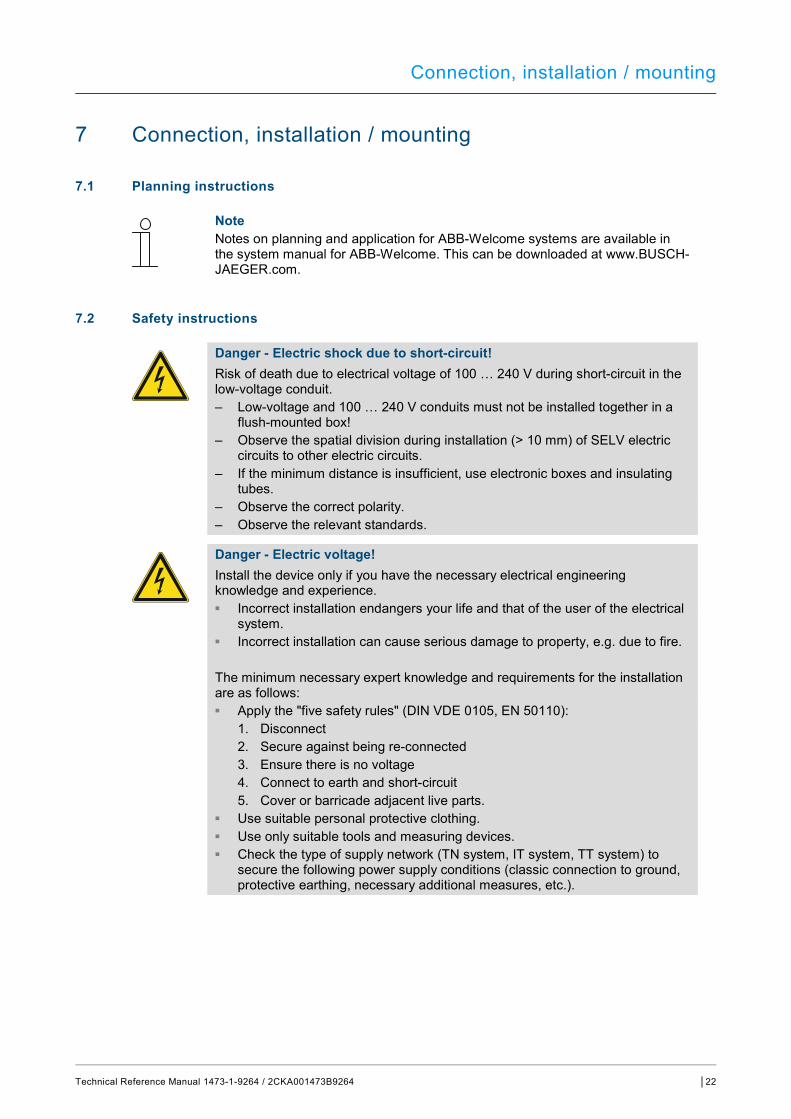
Connection, installation / mounting
Technical Reference Manual 1473-1-9264 / 2CKA001473B9264 │22
7 Connection, installation / mounting
7.1 Planning instructions
Note Notes on planning and application for ABB-Welcome systems are available in the system manual for ABB-Welcome. This can be downloaded at www.BUSCH-JAEGER.com.
7.2 Safety instructions
Danger - Electric shock due to short-circuit! Risk of death due to electrical voltage of 100 … 240 V during short-circuit in the low-voltage conduit. – Low-voltage and 100 … 240 V conduits must not be installed together in a
flush-mounted box! – Observe the spatial division during installation (> 10 mm) of SELV electric
circuits to other electric circuits. – If the minimum distance is insufficient, use electronic boxes and insulating
tubes. – Observe the correct polarity. – Observe the relevant standards.
Danger - Electric voltage! Install the device only if you have the necessary electrical engineering knowledge and experience. ■ Incorrect installation endangers your life and that of the user of the electrical
system. ■ Incorrect installation can cause serious damage to property, e.g. due to fire. The minimum necessary expert knowledge and requirements for the installation are as follows: ■ Apply the "five safety rules" (DIN VDE 0105, EN 50110):
1. Disconnect 2. Secure against being re-connected 3. Ensure there is no voltage 4. Connect to earth and short-circuit 5. Cover or barricade adjacent live parts.
■ Use suitable personal protective clothing. ■ Use only suitable tools and measuring devices. ■ Check the type of supply network (TN system, IT system, TT system) to
secure the following power supply conditions (classic connection to ground, protective earthing, necessary additional measures, etc.).
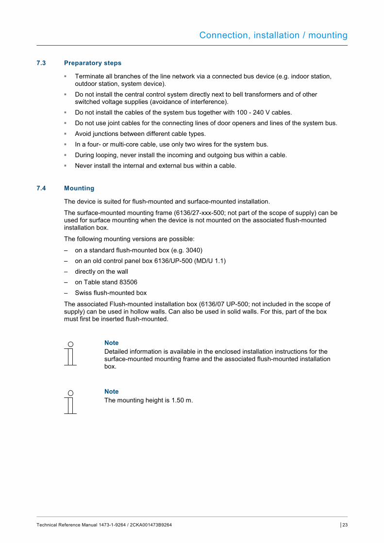
Connection, installation / mounting
Technical Reference Manual 1473-1-9264 / 2CKA001473B9264 │23
7.3 Preparatory steps
■ Terminate all branches of the line network via a connected bus device (e.g. indoor station, outdoor station, system device).
■ Do not install the central control system directly next to bell transformers and of other switched voltage supplies (avoidance of interference).
■ Do not install the cables of the system bus together with 100 - 240 V cables. ■ Do not use joint cables for the connecting lines of door openers and lines of the system bus. ■ Avoid junctions between different cable types. ■ In a four- or multi-core cable, use only two wires for the system bus. ■ During looping, never install the incoming and outgoing bus within a cable. ■ Never install the internal and external bus within a cable.
7.4 Mounting
The device is suited for flush-mounted and surface-mounted installation.
The surface-mounted mounting frame (6136/27-xxx-500; not part of the scope of supply) can be used for surface mounting when the device is not mounted on the associated flush-mounted installation box.
The following mounting versions are possible:
– on a standard flush-mounted box (e.g. 3040) – on an old control panel box 6136/UP-500 (MD/U 1.1) – directly on the wall – on Table stand 83506 – Swiss flush-mounted box
The associated Flush-mounted installation box (6136/07 UP-500; not included in the scope of supply) can be used in hollow walls. Can also be used in solid walls. For this, part of the box must first be inserted flush-mounted.
Note Detailed information is available in the enclosed installation instructions for the surface-mounted mounting frame and the associated flush-mounted installation box.
Note The mounting height is 1.50 m.

Connection, installation / mounting
Technical Reference Manual 1473-1-9264 / 2CKA001473B9264 │24
7.4.1 Overview of mounting versions
Mounting versions, connection and installation of Busch-SmartTouch® 7''
Mounting in flush-mounted installation box
Hollow wall See Page 24
Solid wall See Page 25
Mounting with surface-mounted mounting frame
Surface-mounted mounting frame See Page 26
Connection and installation See Page 28
Table 5: Mounting versions, connection and installation
7.4.2 Mounting in flush-mounted installation box in hollow wall
Note See mounting instructions on the enclosed plaster and drilling template. The bottom part of the flush-mounted installation box in not required here.
Installation on the basis of the instructions on the enclosed drilling template:
Fig. 5: Mounting in hollow wall
Continue with connection and installation Page 28.
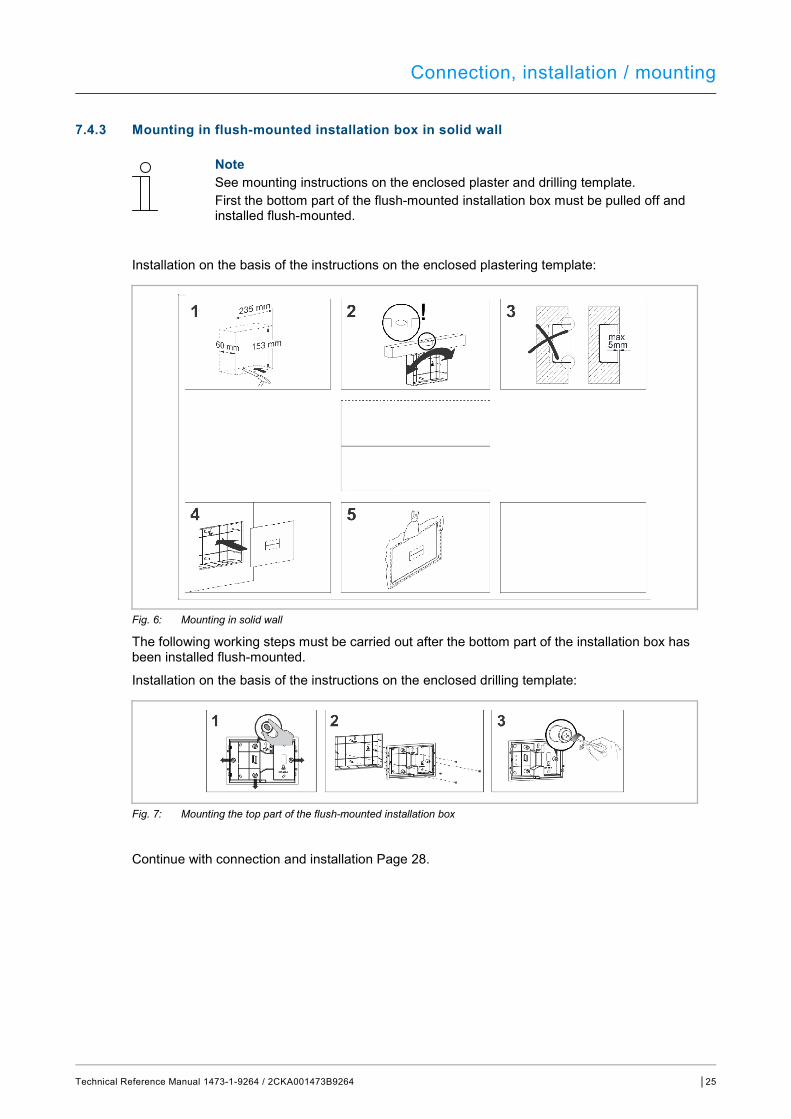
Connection, installation / mounting
Technical Reference Manual 1473-1-9264 / 2CKA001473B9264 │25
7.4.3 Mounting in flush-mounted installation box in solid wall
Note See mounting instructions on the enclosed plaster and drilling template. First the bottom part of the flush-mounted installation box must be pulled off and installed flush-mounted.
Installation on the basis of the instructions on the enclosed plastering template:
Fig. 6: Mounting in solid wall
The following working steps must be carried out after the bottom part of the installation box has been installed flush-mounted.
Installation on the basis of the instructions on the enclosed drilling template:
Fig. 7: Mounting the top part of the flush-mounted installation box
Continue with connection and installation Page 28.
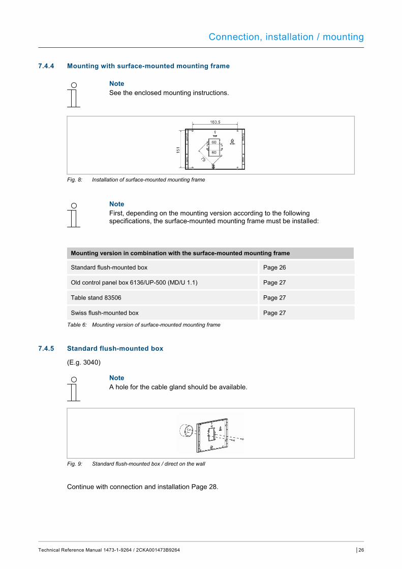
Connection, installation / mounting
Technical Reference Manual 1473-1-9264 / 2CKA001473B9264 │26
7.4.4 Mounting with surface-mounted mounting frame
Note See the enclosed mounting instructions.
Fig. 8: Installation of surface-mounted mounting frame
Note First, depending on the mounting version according to the following specifications, the surface-mounted mounting frame must be installed:
Mounting version in combination with the surface-mounted mounting frame
Standard flush-mounted box Page 26
Old control panel box 6136/UP-500 (MD/U 1.1) Page 27
Table stand 83506 Page 27
Swiss flush-mounted box Page 27
Table 6: Mounting version of surface-mounted mounting frame
7.4.5 Standard flush-mounted box
(E.g. 3040)
Note A hole for the cable gland should be available.
Fig. 9: Standard flush-mounted box / direct on the wall
Continue with connection and installation Page 28.
Connection, installation / mounting
Technical Reference Manual 1473-1-9264 / 2CKA001473B9264 │27
7.4.6 Old control panel box 6136/UP-500 (MD/U 1.1)
Fig. 10: Old control panel box 6136/UP-500 (MD/U 1.1)
Continue with connection and installation Page 28.
7.4.7 Table stand 83506
Fig. 11: Table stand 83506
Continue with connection and installation Page 28.
7.4.8 Swiss flush-mounted box
Fig. 12: Swiss flush-mounted box
Continue with connection and installation Page 28.
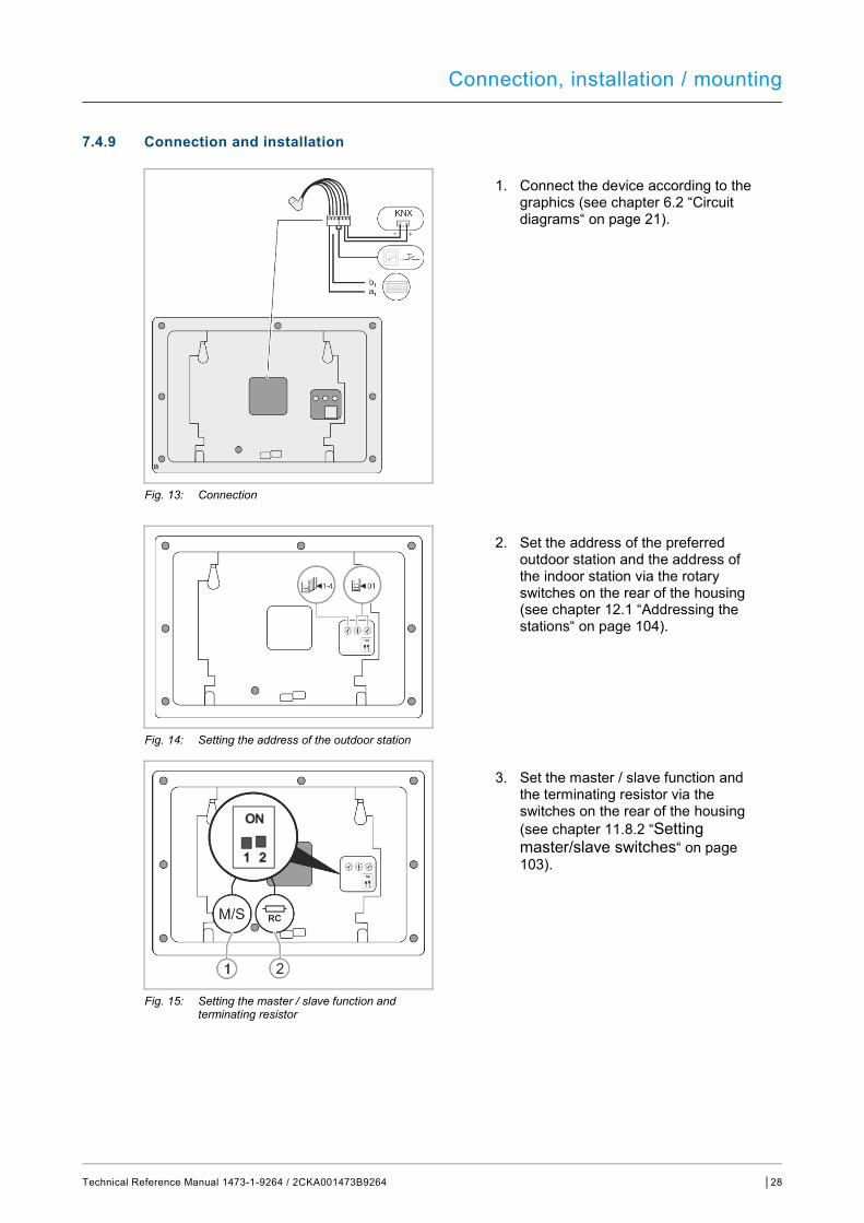
Connection, installation / mounting
Technical Reference Manual 1473-1-9264 / 2CKA001473B9264 │28
7.4.9 Connection and installation
1. Connect the device according to the graphics (see chapter 6.2 “Circuit diagrams“ on page 21).
Fig. 13: Connection
2. Set the address of the preferred outdoor station and the address of the indoor station via the rotary switches on the rear of the housing (see chapter 12.1 “Addressing the stations“ on page 104).
Fig. 14: Setting the address of the outdoor station
3. Set the master / slave function and the terminating resistor via the switches on the rear of the housing (see chapter 11.8.2 “Setting master/slave switches“ on page 103).
Fig. 15: Setting the master / slave function and terminating resistor
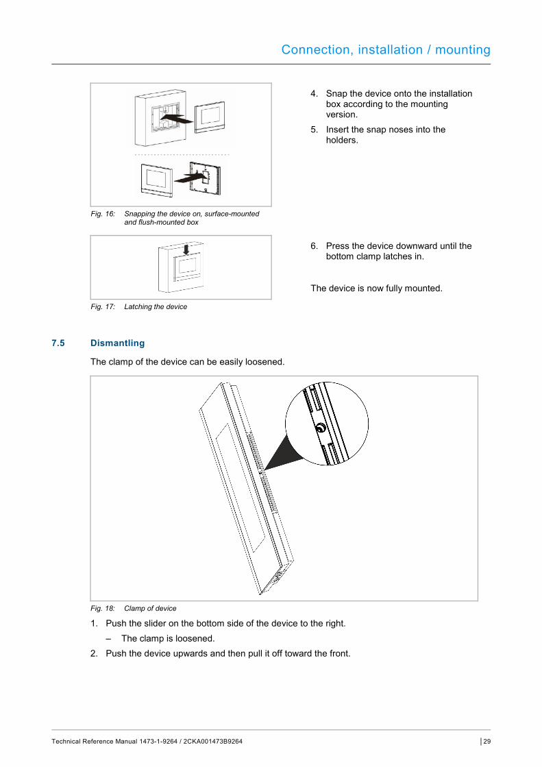
Connection, installation / mounting
Technical Reference Manual 1473-1-9264 / 2CKA001473B9264 │29
4. Snap the device onto the installation box according to the mounting version.
5. Insert the snap noses into the holders.
Fig. 16: Snapping the device on, surface-mounted and flush-mounted box
6. Press the device downward until the bottom clamp latches in.
The device is now fully mounted.
Fig. 17: Latching the device
7.5 Dismantling
The clamp of the device can be easily loosened.
Fig. 18: Clamp of device
1. Push the slider on the bottom side of the device to the right. – The clamp is loosened.
2. Push the device upwards and then pull it off toward the front.
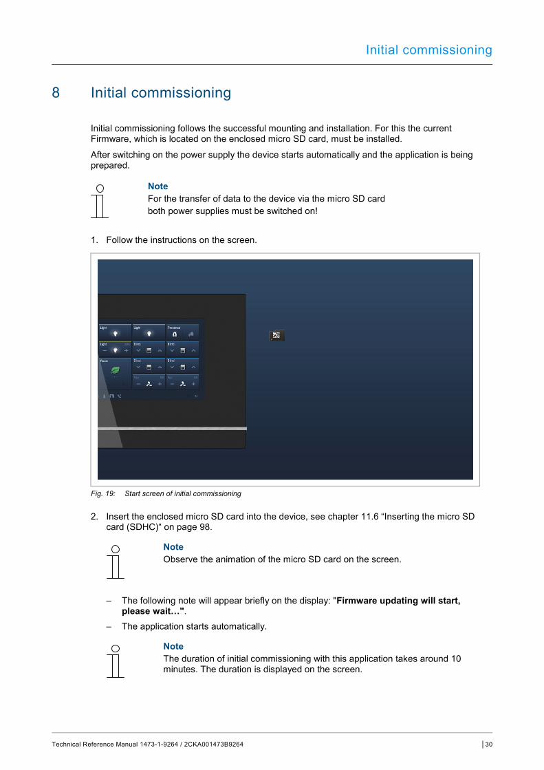
Initial commissioning
Technical Reference Manual 1473-1-9264 / 2CKA001473B9264 │30
8 Initial commissioning
Initial commissioning follows the successful mounting and installation. For this the current Firmware, which is located on the enclosed micro SD card, must be installed.
After switching on the power supply the device starts automatically and the application is being prepared.
Note For the transfer of data to the device via the micro SD card both power supplies must be switched on!
1. Follow the instructions on the screen.
Fig. 19: Start screen of initial commissioning
2. Insert the enclosed micro SD card into the device, see chapter 11.6 “Inserting the micro SD card (SDHC)“ on page 98.
Note Observe the animation of the micro SD card on the screen.
– The following note will appear briefly on the display: "Firmware updating will start, please wait…".
– The application starts automatically.
Note The duration of initial commissioning with this application takes around 10 minutes. The duration is displayed on the screen.
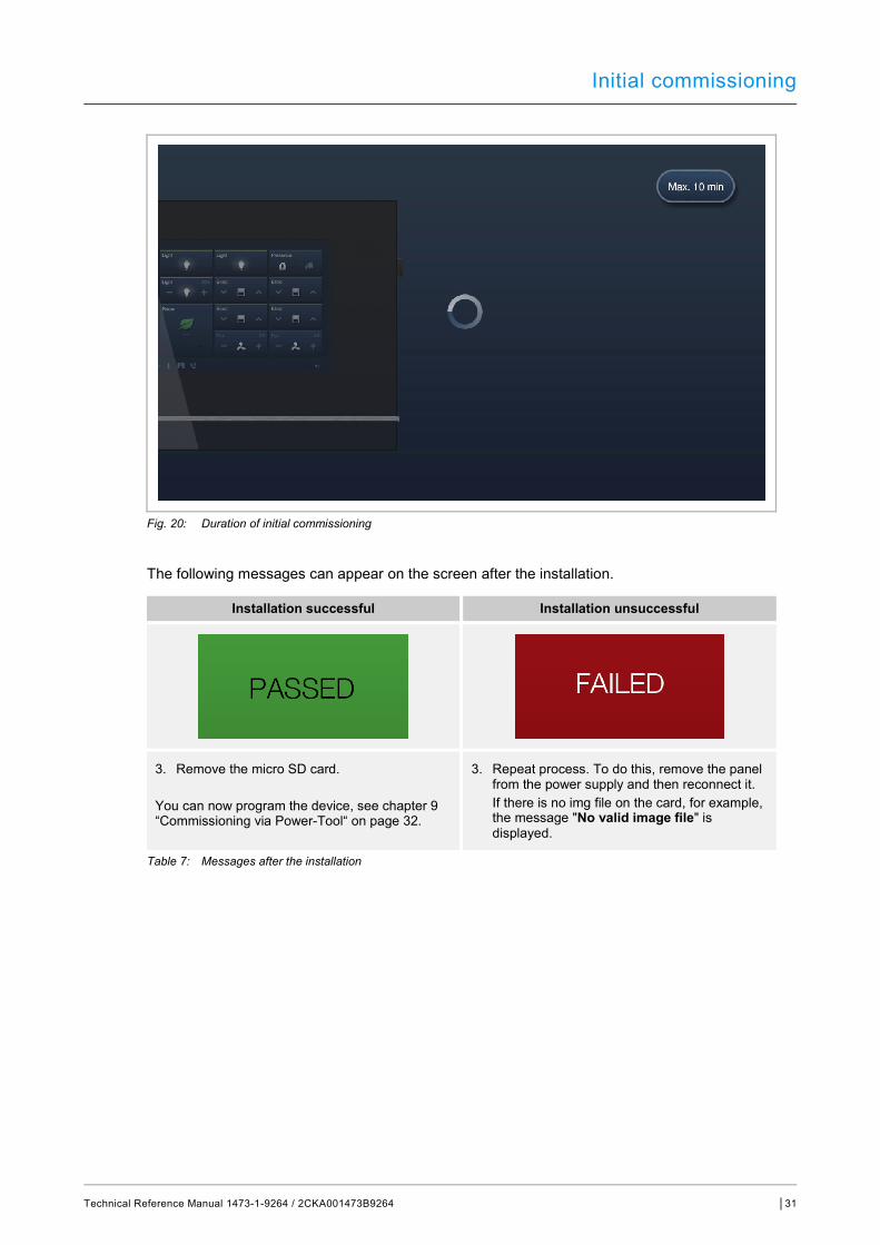
Initial commissioning
Technical Reference Manual 1473-1-9264 / 2CKA001473B9264 │31
Fig. 20: Duration of initial commissioning
The following messages can appear on the screen after the installation.
Installation successful Installation unsuccessful
3. Remove the micro SD card. You can now program the device, see chapter 9 “Commissioning via Power-Tool“ on page 32.
3. Repeat process. To do this, remove the panel from the power supply and then reconnect it.
If there is no img file on the card, for example, the message "No valid image file" is displayed.
Table 7: Messages after the installation
Commissioning via Power-Tool
Technical Reference Manual 1473-1-9264 / 2CKA001473B9264 │32
9 Commissioning via Power-Tool
Commissioning the Busch-SmartTouch® 7'' via the plug-in Power-Tool for SmartTouch.
9.1 Integration into the KNX system (ETS)
Note The device meets KNX guidelines and can be used as product of the KNX system. Detailed expert knowledge for understanding by means of KNX training is assumed, especially with regard to the commissioning software ETS.
9.1.1 Installation of the plug-in Power-Tool for the Busch-SmartTouch®
To display the special Power-Tool commissioning tool, the plug-in Power-Tool must be installed for the Busch-SmartTouch® 7''.
This plug-in can then be called up in the ETS via an additional button "Open product-specific parameter dialogue". For this a licensed version of the ETS Professional Software must be installed on the target computer for the installation. At least Version ETS3 is required.
Note The plugin for the ETSx can be downloaded via the electronic catalogue www.busch-jaeger-catalogue.com. For a Power-Tool that has already been installed (from version 1.2.38) also an online update can be made. For this, see the description of the Power-Tool update.
9.1.2 Installation sequence
An installation wizard will assist you with the installation of the plug-in Power-Tool for the Busch-SmartTouch® 7''.
1. Start the install wizard by double clicking the file "PT2Setup_x_x_x.exe". – A dialogue window with available languages opens.
2. Select the install language (DE or EN). 3. Click on "OK".
Note For a Power-Tool that has already been installed (from version 1.2.38) also an online update can be made. For this, see the description of the Power-Tool update.
Commissioning via Power-Tool
Technical Reference Manual 1473-1-9264 / 2CKA001473B9264 │33
9.1.3 Integrating the Busch-SmartTouch® 7'' into the ETS
1. Start the ETS. 2. Import the product data of the Busch-SmartTouch® 7'' into the project database via the
import function of the ETS. – File type ETS3: *.vd5). – File type ETS4 and ETS5: *.knxprod).
9.1.4 Further KNX settings in the Busch-SmartTouch® 7''
All KNX settings for the Busch-SmartTouch® 7'' are made via the Power-Tool commissioning tool, which is a component part of the special ETSx plug-in for the Busch-SmartTouch® 7'' (see chapter 9.1.1 “Installation of the plug-in Power-Tool for the Busch-SmartTouch®“ on page 32).

Commissioning via Power-Tool
Technical Reference Manual 1473-1-9264 / 2CKA001473B9264 │34
9.2 Overview of the Power-Tool commissioning tool
The following section includes basic information about the Power-Tool commissioning tool.
Power-Tool is a project planning software with which you can configure the Busch-SmartTouch® 7'' for the ABB building automation. Every Busch-SmartTouch® 7'' can be set up individually. Power-Tool leads you through the configuration during project planning.
Important tasks for project planning with Power-Tool are: ■ Specifying fundamental settings, e.g. display language for the Busch-SmartTouch® 7''
(system settings). ■ Specifying the navigation structure, e.g. creation of floors and rooms with associated
operating pages. ■ Configuration of existing applications. ■ Configuration of pages, e.g. arrangement of buttons. ■ Configuration of control elements, e.g. selection of button icons. ■ Linking with group addresses to establish the connection to actuators and sensors via the
bus. ■ Commissioning via a micro SD card.
Note Basic information for operation and the views of the Power-Tool is contained in the online Help of the plug-in. This can be opened via menu item "Help" in menu "Help".
9.2.1 Starting the Power-Tool
1. Start the ETS software (double-click on the program icon or via the start menu of the operating system (Start -> Programs -> KNX -> ETSx)). – The overview window of the ETS opens.
2. Open an existing project file or create a new project. – The main window of the ETS opens.
Note Detailed knowledge of ETS operation is assumed for project planning. It is recommended to first import the product data into the project database (see chapter 9.1.3 “Integrating the Busch-SmartTouch® 7'' into the ETS “ on page 33).
3. Integrate the device into the project via the catalogue. 4. Select the device. 5. Click on "Parameters" in the device window. 6. Click on "Open product-specific parameter dialogue".
– Power-Tool opens in a separate window.
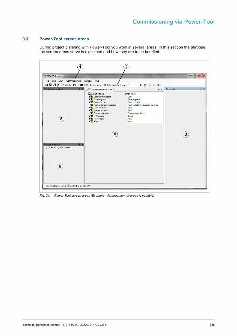
Commissioning via Power-Tool
Technical Reference Manual 1473-1-9264 / 2CKA001473B9264 │35
9.3 Power-Tool screen areas
During project planning with Power-Tool you work in several areas. In this section the purpose the screen areas serve is explained and how they are to be handled.
Fig. 21: Power-Tool screen areas (Example - Arrangement of areas is variable)
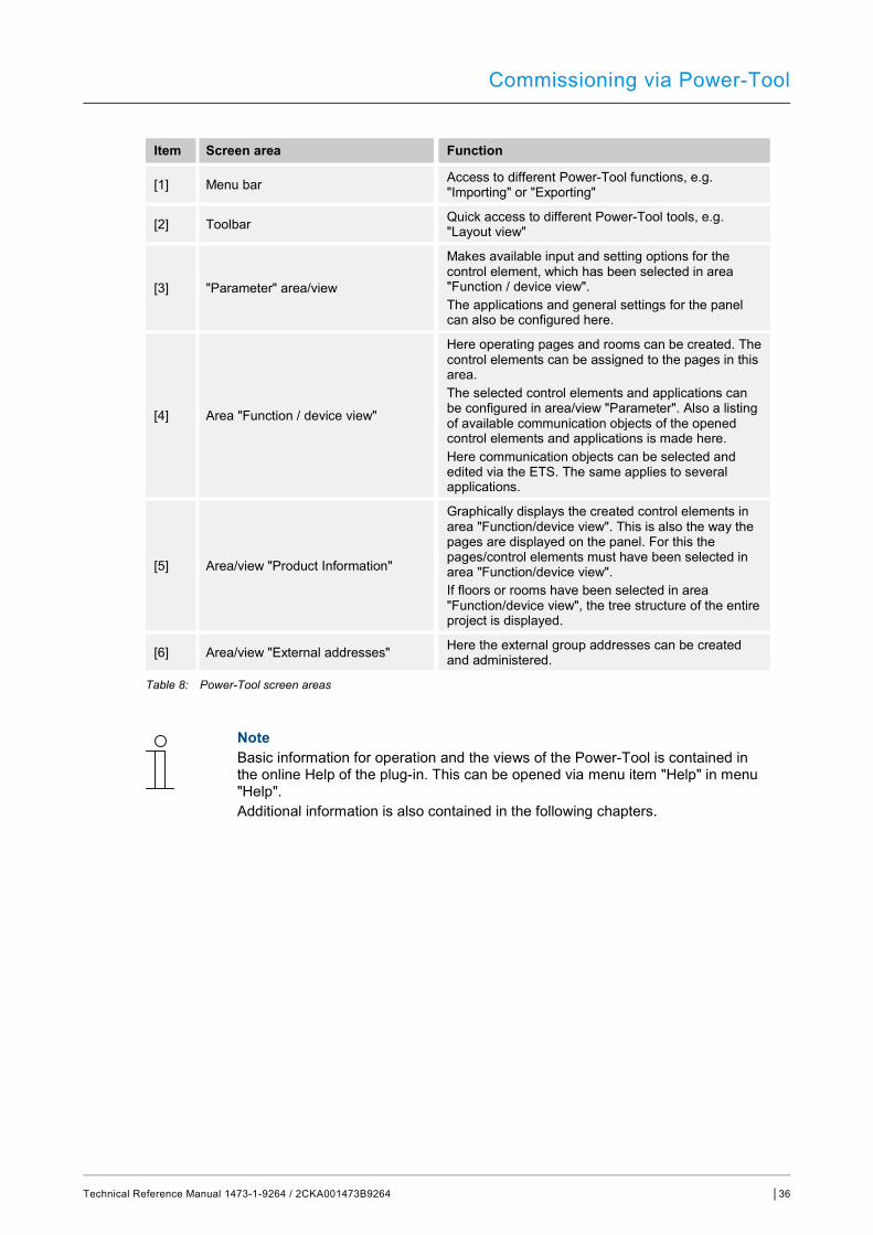
Commissioning via Power-Tool
Technical Reference Manual 1473-1-9264 / 2CKA001473B9264 │36
Item Screen area Function
[1] Menu bar Access to different Power-Tool functions, e.g. "Importing" or "Exporting"
[2] Toolbar Quick access to different Power-Tool tools, e.g. "Layout view"
[3] "Parameter" area/view
Makes available input and setting options for the control element, which has been selected in area "Function / device view". The applications and general settings for the panel can also be configured here.
[4] Area "Function / device view"
Here operating pages and rooms can be created. The control elements can be assigned to the pages in this area. The selected control elements and applications can be configured in area/view "Parameter". Also a listing of available communication objects of the opened control elements and applications is made here. Here communication objects can be selected and edited via the ETS. The same applies to several applications.
[5] Area/view "Product Information"
Graphically displays the created control elements in area "Function/device view". This is also the way the pages are displayed on the panel. For this the pages/control elements must have been selected in area "Function/device view". If floors or rooms have been selected in area "Function/device view", the tree structure of the entire project is displayed.
[6] Area/view "External addresses" Here the external group addresses can be created and administered.
Table 8: Power-Tool screen areas
Note Basic information for operation and the views of the Power-Tool is contained in the online Help of the plug-in. This can be opened via menu item "Help" in menu "Help". Additional information is also contained in the following chapters.
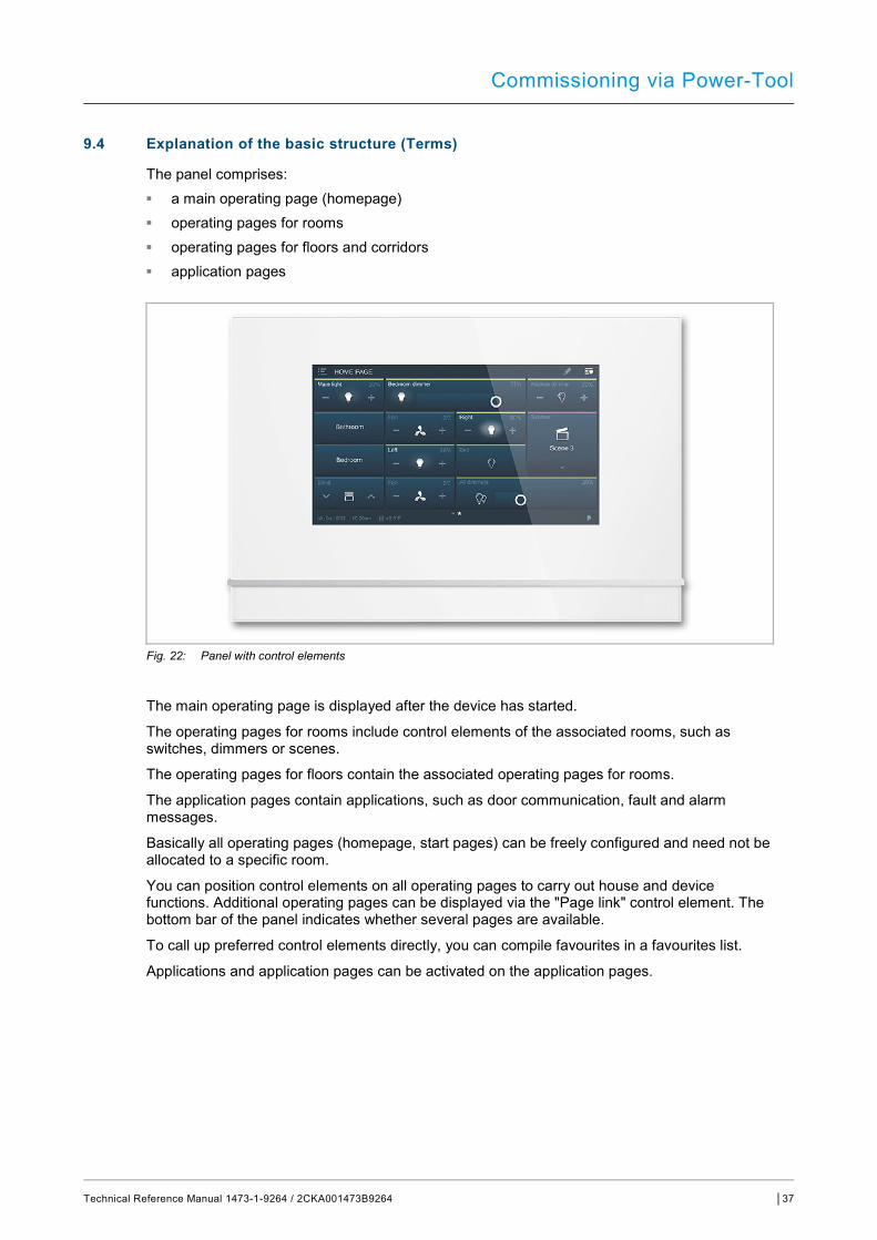
Commissioning via Power-Tool
Technical Reference Manual 1473-1-9264 / 2CKA001473B9264 │37
9.4 Explanation of the basic structure (Terms)
The panel comprises: ■ a main operating page (homepage) ■ operating pages for rooms ■ operating pages for floors and corridors ■ application pages
Fig. 22: Panel with control elements
The main operating page is displayed after the device has started.
The operating pages for rooms include control elements of the associated rooms, such as switches, dimmers or scenes.
The operating pages for floors contain the associated operating pages for rooms.
The application pages contain applications, such as door communication, fault and alarm messages.
Basically all operating pages (homepage, start pages) can be freely configured and need not be allocated to a specific room.
You can position control elements on all operating pages to carry out house and device functions. Additional operating pages can be displayed via the "Page link" control element. The bottom bar of the panel indicates whether several pages are available.
To call up preferred control elements directly, you can compile favourites in a favourites list.
Applications and application pages can be activated on the application pages.
Commissioning via Power-Tool
Technical Reference Manual 1473-1-9264 / 2CKA001473B9264 │38
Navigation If you swipe to the right on the main operating page of the Busch-SmartTouch® 7'', the configured application pages and basic settings are displayed in a menu.
If you swipe to the left on the main operating page, the created operating pages are displayed.
If several operating and application pages have been created on a level, you can call them up by swiping to the left or to the right.
Note Additional explanations are available in Chapter 11 “Operation“ on page 70.
9.5 Commissioning sequence
To be able to work with the Power-Tool commissioning tool as effectively as possible, the following work sequence (standard workflow) is recommended:
1. Start the ETS software (see chapter 9.2.1 “Starting the Power-Tool“ on page 34). 2. Create a new project or open an existing one. 3. Start the Power-Tool. 4. Configure basic settings for the panel. 5. Create the navigation structure (see chapter 9.7 “Creation of the navigation structure“ on
page 53). 6. Configure the operating pages (insert and configure control elements). 7. Configure the applications and application pages. 8. Edit the available communication objects. 9. Create group addresses and allocate the correct data point type (DPT) to all group
addresses used in the Busch-SmartTouch® 7'' (e.g. function: 1.001 switch). 10. Transfer the project to the panel and start operation.
9.6 Configuring basic settings for the panel
The basic settings for the panel can be specified beforehand.
1. Select the "System settings" in area "Function/device view". – The basic settings are displayed in the "Parameter" area and can be edited (see chapter
9.6.1 “Basic settings (system settings) of the panel“ on page 39). – Available communication objects for certain functions are displayed in the
"Function/device view" area and can be used. For this, click on the "+" each time for the control elements or applications.
– Group addresses can be allocated via the "External addresses" area.
Note Some basic settings can be adjusted directly in the panel. For this the setting "Enable system settings for end customers" must be set on "Yes".
Commissioning via Power-Tool
Technical Reference Manual 1473-1-9264 / 2CKA001473B9264 │39
9.6.1 Basic settings (system settings) of the panel
Note Entries in text fields must be confirmed with the return key. Click in the field in the list fields and then make a selection.
General ■ Panel language
Options: <Selection of language from a list>
The parameter is used to specify the language of the user interface. Selection: 1. Click in the field.
– The list with available languages opens. 2. Select the language.
■ Acoustic signal at press of button
Options: Yes
No
The parameter is used to specify whether an acoustic signal is issued by the device when a button is pressed.
■ Default setting of volume of acoustic signal [%]
Options: Setting option from 10 - 100%
The parameter is used to set the volume for the acoustic signal when a button is pressed. Entry: 1. Click in the input field and enter a percentage. Or: 1. Click in the field. 2. Click on the arrows.
Note The parameter is available only if the "Acoustic signal at press of button" is set on "Yes".
Commissioning via Power-Tool
Technical Reference Manual 1473-1-9264 / 2CKA001473B9264 │40
■ Decimal separator
Options: Comma
Dot
The parameter is used to specify whether a comma or a dot is used as decimal separator.
■ Thousands separator
Options: Comma
Dot
The parameter is used to specify whether thousands are separated with a comma or a dot.
■ Time format
Options: 12 h
24 h
The parameter is used to specify in which format the time is displayed. The default setting is the 24-hour display.
■ Date format
Options: DD-MM-YY
MM/DD/YY
DD/MM/YY
YY-MM-DD
YY.MM.DD
The parameter is used to specify the date format. Selection: 1. Click in the field.
– The list with available date formats opens. 2. Select date format.
– DD: Day, MM: Month, YY: Year. Example: 01-12-17 (DD-MM-YY)
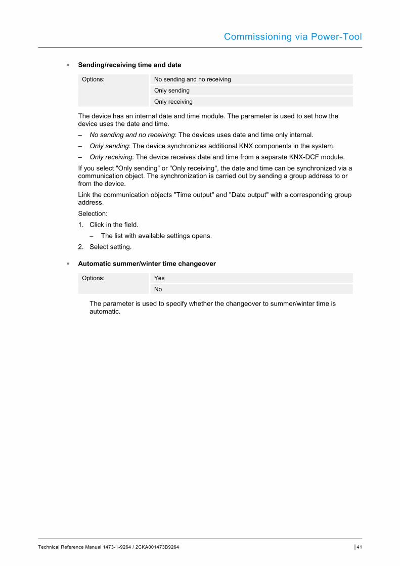
Commissioning via Power-Tool
Technical Reference Manual 1473-1-9264 / 2CKA001473B9264 │41
■ Sending/receiving time and date
Options: No sending and no receiving
Only sending
Only receiving
The device has an internal date and time module. The parameter is used to set how the device uses the date and time. – No sending and no receiving: The devices uses date and time only internal. – Only sending: The device synchronizes additional KNX components in the system. – Only receiving: The device receives date and time from a separate KNX-DCF module.
If you select "Only sending" or "Only receiving", the date and time can be synchronized via a communication object. The synchronization is carried out by sending a group address to or from the device.
Link the communication objects "Time output" and "Date output" with a corresponding group address. Selection: 1. Click in the field.
– The list with available settings opens. 2. Select setting.
■ Automatic summer/winter time changeover
Options: Yes
No
The parameter is used to specify whether the changeover to summer/winter time is automatic.
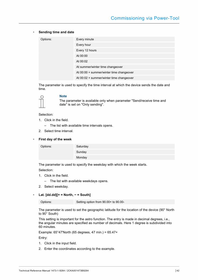
Commissioning via Power-Tool
Technical Reference Manual 1473-1-9264 / 2CKA001473B9264 │42
■ Sending time and date
Options: Every minute
Every hour
Every 12 hours
At 00:00
At 00:02
At summer/winter time changeover
At 00:00 + summer/winter time changeover
At 00:02 + summer/winter time changeover
The parameter is used to specify the time interval at which the device sends the date and time.
Note The parameter is available only when parameter "Send/receive time and date" is set on "Only sending".
Selection: 1. Click in the field.
– The list with available time intervals opens. 2. Select time interval.
■ First day of the week
Options: Saturday
Sunday
Monday
The parameter is used to specify the weekday with which the week starts. Selection: 1. Click in the field.
– The list with available weekdays opens. 2. Select weekday.
■ Lat. [dd.dd][+ = North, − = South]
Options: Setting option from 90.00+ to 90.00-
The parameter is used to set the geographic latitude for the location of the device (90° North to 90° South)
This setting is important for the astro function. The entry is made in decimal degrees, i.e., the angular minutes are specified as number of decimals. Here 1 degree is subdivided into 60 minutes.
Example: 65°47′North (65 degrees, 47 min.) = 65.47+ Entry: 1. Click in the input field. 2. Enter the coordinates according to the example.
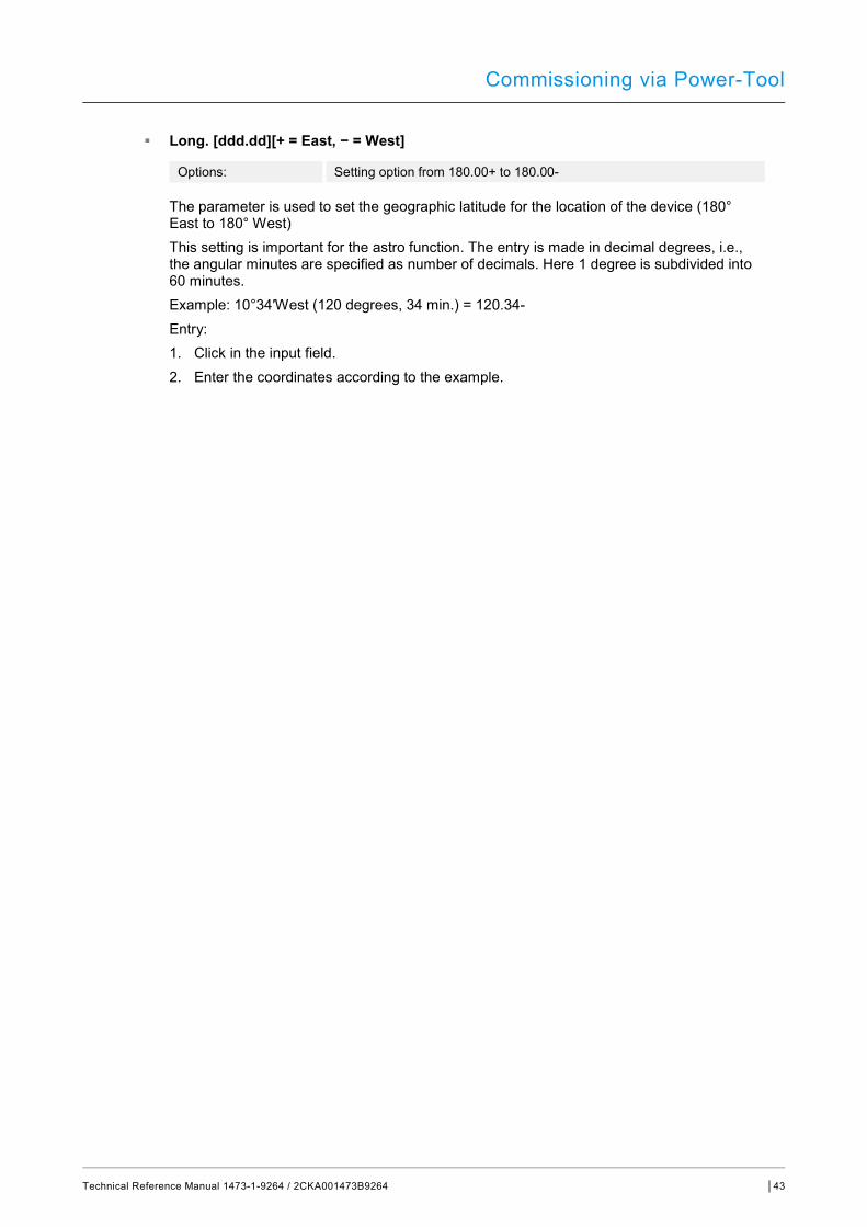
Commissioning via Power-Tool
Technical Reference Manual 1473-1-9264 / 2CKA001473B9264 │43
■ Long. [ddd.dd][+ = East, − = West]
Options: Setting option from 180.00+ to 180.00-
The parameter is used to set the geographic latitude for the location of the device (180° East to 180° West)
This setting is important for the astro function. The entry is made in decimal degrees, i.e., the angular minutes are specified as number of decimals. Here 1 degree is subdivided into 60 minutes.
Example: 10°34′West (120 degrees, 34 min.) = 120.34- Entry: 1. Click in the input field. 2. Enter the coordinates according to the example.
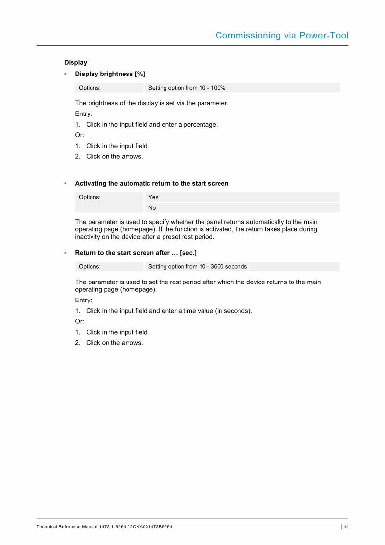
Commissioning via Power-Tool
Technical Reference Manual 1473-1-9264 / 2CKA001473B9264 │44
Display ■ Display brightness [%]
Options: Setting option from 10 - 100%
The brightness of the display is set via the parameter. Entry: 1. Click in the input field and enter a percentage. Or: 1. Click in the input field. 2. Click on the arrows.
■ Activating the automatic return to the start screen
Options: Yes
No
The parameter is used to specify whether the panel returns automatically to the main operating page (homepage). If the function is activated, the return takes place during inactivity on the device after a preset rest period.
■ Return to the start screen after … [sec.]
Options: Setting option from 10 - 3600 seconds
The parameter is used to set the rest period after which the device returns to the main operating page (homepage). Entry: 1. Click in the input field and enter a time value (in seconds). Or: 1. Click in the input field. 2. Click on the arrows.
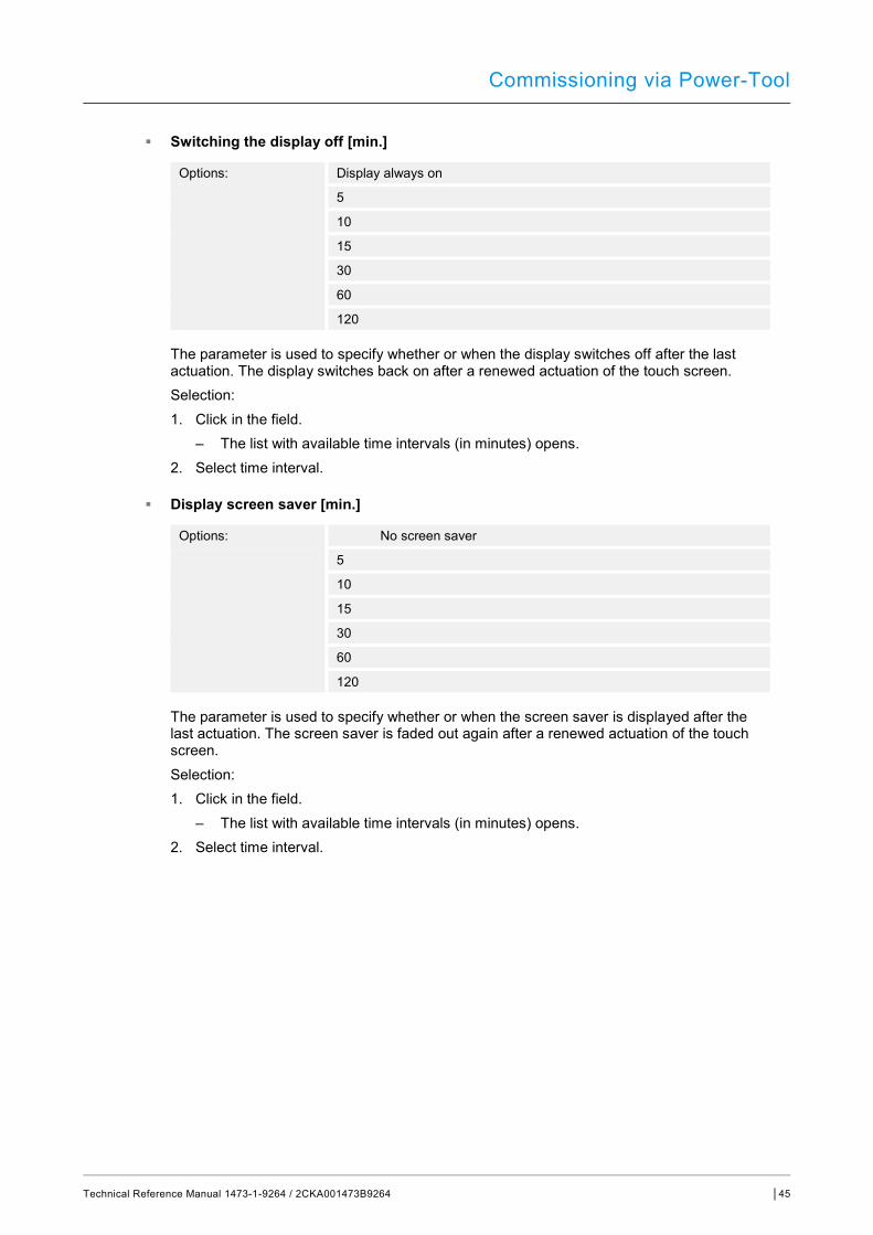
Commissioning via Power-Tool
Technical Reference Manual 1473-1-9264 / 2CKA001473B9264 │45
■ Switching the display off [min.]
Options: Display always on
5
10
15
30
60
120
The parameter is used to specify whether or when the display switches off after the last actuation. The display switches back on after a renewed actuation of the touch screen. Selection: 1. Click in the field.
– The list with available time intervals (in minutes) opens. 2. Select time interval.
■ Display screen saver [min.]
Options: No screen saver
5
10
15
30
60
120
The parameter is used to specify whether or when the screen saver is displayed after the last actuation. The screen saver is faded out again after a renewed actuation of the touch screen. Selection: 1. Click in the field.
– The list with available time intervals (in minutes) opens. 2. Select time interval.
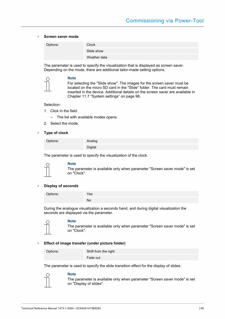
Commissioning via Power-Tool
Technical Reference Manual 1473-1-9264 / 2CKA001473B9264 │46
■ Screen saver mode
Options: Clock
Slide show
Weather data
The parameter is used to specify the visualization that is displayed as screen saver. Depending on the mode, there are additional tailor-made setting options.
Note For selecting the "Slide show": The images for the screen saver must be located on the micro SD card in the "Slide" folder. The card must remain inserted in the device. Additional details on the screen saver are available in Chapter 11.7 “System settings“ on page 98.
Selection: 1. Click in the field.
– The list with available modes opens. 2. Select the mode.
■ Type of clock
Options: Analog
Digital
The parameter is used to specify the visualization of the clock.
Note The parameter is available only when parameter "Screen saver mode" is set on "Clock".
■ Display of seconds
Options: Yes
No
During the analogue visualization a seconds hand, and during digital visualization the seconds are displayed via the parameter.
Note The parameter is available only when parameter "Screen saver mode" is set on "Clock".
■ Effect of image transfer (under picture folder)
Options: Shift from the right
Fade out
The parameter is used to specify the slide transition effect for the display of slides.
Note The parameter is available only when parameter "Screen saver mode" is set on "Display of slides".
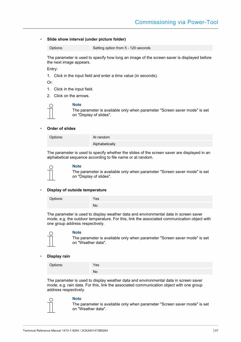
Commissioning via Power-Tool
Technical Reference Manual 1473-1-9264 / 2CKA001473B9264 │47
■ Slide show interval (under picture folder)
Options: Setting option from 5 - 120 seconds
The parameter is used to specify how long an image of the screen saver is displayed before the next image appears. Entry: 1. Click in the input field and enter a time value (in seconds). Or: 1. Click in the input field. 2. Click on the arrows.
Note The parameter is available only when parameter "Screen saver mode" is set on "Display of slides".
■ Order of slides
Options: At random
Alphabetically
The parameter is used to specify whether the slides of the screen saver are displayed in an alphabetical sequence according to file name or at random.
Note The parameter is available only when parameter "Screen saver mode" is set on "Display of slides".
■ Display of outside temperature
Options: Yes
No
The parameter is used to display weather data and environmental data in screen saver mode, e.g. the outdoor temperature. For this, link the associated communication object with one group address respectively.
Note The parameter is available only when parameter "Screen saver mode" is set on "Weather data".
■ Display rain
Options: Yes
No
The parameter is used to display weather data and environmental data in screen saver mode, e.g. rain data. For this, link the associated communication object with one group address respectively.
Note The parameter is available only when parameter "Screen saver mode" is set on "Weather data".
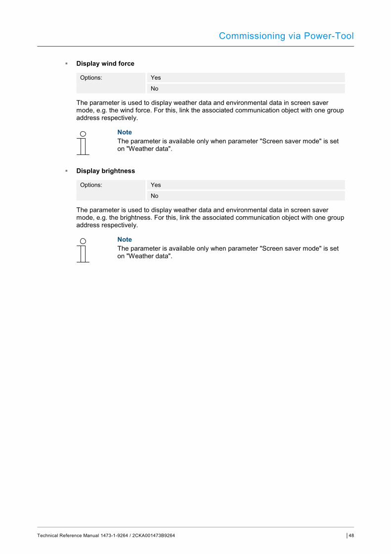
Commissioning via Power-Tool
Technical Reference Manual 1473-1-9264 / 2CKA001473B9264 │48
■ Display wind force
Options: Yes
No
The parameter is used to display weather data and environmental data in screen saver mode, e.g. the wind force. For this, link the associated communication object with one group address respectively.
Note The parameter is available only when parameter "Screen saver mode" is set on "Weather data".
■ Display brightness
Options: Yes
No
The parameter is used to display weather data and environmental data in screen saver mode, e.g. the brightness. For this, link the associated communication object with one group address respectively.
Note The parameter is available only when parameter "Screen saver mode" is set on "Weather data".
Commissioning via Power-Tool
Technical Reference Manual 1473-1-9264 / 2CKA001473B9264 │49
Temperature
Note The temperature parameters refer to the temperature display in the bottom bar of the display.
■ Temperature unit
Options: °C
°F
The parameter is used to specify the display of the temperature in units of °C (Celsius) or °F (Fahrenheit).
■ Display room temperature
Options: Yes
No
The parameter is used to specify whether the current measured temperature value of the indoor temperature sensor is displayed.
Note Room and outdoor temperature share a display location in the bottom bar of the display. They are displayed alternately when both parameters are activated.
■ Display of outside temperature
Options: Yes
No
The parameter is used to specify whether the current measured temperature value of an outdoor temperature sensor, which has been allocated via a group address, is displayed.
Note Room and outdoor temperature share a display location in the bottom bar of the display. They are displayed alternately when both parameters are activated.
■ Room/outdoor temperature change interval [sec.]
Options: Setting option from 3 - 10 seconds
Room and outdoor temperature share a display location in the bottom bar of the display. The parameter is used to specify the time after which the display of the temperatures changes. Entry: 1. Click in the input field and enter a time interval (in seconds). Or: 1. Click in the input field. 2. Click on the arrows.
Commissioning via Power-Tool
Technical Reference Manual 1473-1-9264 / 2CKA001473B9264 │50
Note The parameter is available only when parameter "Display room temperature" is set on "Yes".
■ Use for room temperature sensor
Options: Indoor sensor
Outdoor sensor
The parameter is used to specify whether the room temperature is measured via the indoor sensor of the device or via an outdoor KNX temperature sensor.
The outdoor sensor must be allocated via a group address.
■ Compensating value for temperature measurement (x 0.1K) [K]
Options: Setting option from -128 - +127 K
The parameter is used to specify the value by which the measured temperature is raised or lowered. This compensating value ensures that the correct temperature is displayed and, if necessary, passed on to other devices. A compensation, for example, is necessary when adjoining heat sources distort the measured result. Entry: 1. Click in the input field and enter a compensating value (in Kelvin). Or: 1. Click in the input field. 2. Click on the arrows.
Note The parameter is available only when parameter "Use for room temperature sensor" is set on "Indoor sensor".
■ Send indoor sensor temperature
Options: Do not send
During change
Cyclic
During change and cyclic
The parameter is used to specify whether or when the temperature values of the indoor sensor are passed on to other devices.
Commissioning via Power-Tool
Technical Reference Manual 1473-1-9264 / 2CKA001473B9264 │51
Safety Certain areas of the Busch-SmartTouch® 7'', e.g. operating pages, can be protected against unauthorized access. The access protection is indicated in the display by means of a lock symbol in the bottom bar.
When actuating a control element or an application when the access protection is activated, the user must first enter a security number (PIN code) to enable the function.
■ Length of the PIN code
Options: 4-digit
5-digit
6-digit
The parameter is used to specify the number of digits of the PIN code.
■ PIN codes can be changed by the end customer
Options: Yes
No
The parameter is used to specify whether the PIN codes can be changed by the end customer. They can then be changed by the customer directly on the device. This function can be protected by a code (see parameter "Enable system settings for end customers").
■ Enable system settings for end customer
Options: Yes
With code
The parameter is used to specify how the end customer can access the system settings of the device. The access can be protected by a code. – Yes: Access to the system settings without code. – With code: Access to the system settings with code. The code is specified in parameter
"Code for system settings [0000xx…9999xx]".
■ Code for system settings [0000xx..9999xx]
Options: Setting option from 0000xx - 9999xx
The parameter is used to specify the code for access to the system settings. Entry: 1. Click in the input field and enter a 4-, 5-, or 6-digit code. Or: 1. Click in the input field. 2. Click on the arrows.
Note The length of the code is specified via parameter "Length of PIN code".
Commissioning via Power-Tool
Technical Reference Manual 1473-1-9264 / 2CKA001473B9264 │52
■ PIN code level 1-5
Options: Setting option from 1 - 5
Up to 5 access levels can be created via the parameter. A separate security number (PIN code) can be specified for each access level. This makes 5 access levels with 5 different security numbers possible.
An access level can then be assigned to a specific area of the Busch-SmartTouch® 7''. Example: If access level 1 has been assigned to an operating page, the PIN code of access
level 1 must be entered to gain access. Entry: 1. Click in the input field and enter the number of levels. Or: 1. Click in the input field. 2. Click on the arrows.
Commissioning via Power-Tool
Technical Reference Manual 1473-1-9264 / 2CKA001473B9264 │53
9.7 Creation of the navigation structure
The panel contains operating pages (start pages) for operating the Busch-SmartTouch® 7''. These pages must be created beforehand. Generally a main start page is created (see chapter 9.4 “Explanation of the basic structure (Terms)“ on page 37).
Operating pages can also be created for floors and rooms and assigned to them.
A total of 30 operating pages can be created.
9.7.1 Creating operating pages (start pages)
1. In area "Function/device view", click on the plus sign to the left of "Pages". – Generally the main operating page (homepage) has already been created. This is
displayed in the tree structure in area "Product information". There is also a plus sign in area "Function/device view" next to "Homepage". This plus sign can be used to configure the operating page.
Adding further operating pages 1. In area "Function/device view", click on the field to the right of "Page xx". 2. Click on "Page settings" in the options list. 3. Enter an individual page name in the "Name" field. 4. Click on "OK".
– The further page is displayed graphically in area "Product information". Also a list with the control elements (16 control elements) available for this operating page is opened in area "Function/device view". This can be used to configure the operating page.
Note The created operating pages can also be displayed in the tree structure in area "Product information". For this, click on "Pages" in the "Function/device view" area.
9.7.2 Creating operating pages for rooms
. In area "Function/device view", click on the plus sign to the left of "Floor/room".
Add room 1. In area "Function/device view", click on the field to the right of "Room xx". 2. Click on "Room settings" in the options list. 3. Enter an individual room name in the "Name" field. 4. Click on "OK".
– The room is displayed in the tree structure.
The assignment can now be made to a floor (if created) in area "Parameter". Also name and icon of the room can be adjusted.
The room can also be marked as non-visible. Then it is not displayed in the room listing. However, the pages can still be allocated.
Commissioning via Power-Tool
Technical Reference Manual 1473-1-9264 / 2CKA001473B9264 │54
Create and add operating page for the room 1. In area "Function/device view", click on the field to the right of "Page xx". 2. Click on "Page settings" in the options list. 3. Enter an individual page name in the "Name" field. 4. The corresponding room can be assigned via the "Room" field. 5. Click on "OK".
– The further page is displayed graphically in area "Product information". Also a list with the control elements (16 control elements) available for this operating page is opened in area "Function/device view". This can be used to configure the operating page.
Note A maximum of 3 operating pages can be created per room. The created rooms with the operating pages can also be displayed in the tree structure in area "Product information". For this, click on "Floor/room" in the "Function/device view" area.
Note The pages of a room can be called up in the panel via the icon at the top left in the title bar, see chapter 11.1 “General control and display functions“ on page 70.
9.7.3 Creating operating pages for floors
1. In area "Function/device view", click on the plus sign to the left of "Floor/room".
Add floor 1. In area "Function/device view", click on the field to the right of "Floor xx".
– The floor is displayed in the tree structure.
Now the name and icon of the floor can be adjusted in area "Parameter".
The floor can also be marked as non-visible. Then it is not displayed in the floor listing. However, the rooms can still be allocated.
Rooms (which contain operating pages) can be added to floors, see chapter 9.7.2 “Creating operating pages for rooms“ on page 53. The created floors are then displayed in the assignment lists of the created rooms.
Note The created floors with the operating pages can also be displayed in the tree structure in area "Product information". For this, click on "Floor/room" in the "Function/device view" area.
Note The operating pages of a floor can be called up in the panel via the icon at the top left in the title bar, see chapter 11.1 “General control and display functions“ on page 70.
Commissioning via Power-Tool
Technical Reference Manual 1473-1-9264 / 2CKA001473B9264 │55
9.7.4 Editing operating pages
Modify name of the page 1. In area "Function/device view", click on the plus sign to the left of "Pages". 2. In the list, click on the page whose name is to be adjusted. 3. Adjust the name in the "Parameter" area.
Copy the page and paste it 1. In area "Function/device view", click on the plus sign to the left of "Pages". 2. In the list, use the right mouse button to click on a page that has not yet been created.
– A pop-up menu opens. 3. Click on the arrow next to "Take over parameter settings from..." (only possible if several
pages have been created). 4. Select an existing page in the list.
– The page is copied and transferred to the newly created page with all entries.
Note If also the room assignment is to be taken over, then the command "Take over parameter settings/assignments from..." is to be used.
Delete page 1. In area "Function/device view", click on the plus sign to the left of "Pages". 2. In the list, click on a page with the right mouse button that is to be deleted.
– A pop-up menu opens. 3. Click on "Reset" in the options list. 4. Confirm the displayed message.
– The page is deleted with all entries.
Note The main operating page cannot be deleted.
Modify access to pages 1. In area "Function/device view", click on the plus sign to the left of "Pages". 2. In the list, click on the page whose access setting is to be adjusted. 3. Adjust the access setting in the "Parameter" area.
– It can be specified whether the page can be called up with or without a PIN code. – If the function has been activated, also the PIN code level can be specified.
Note The PIN code is specified via the system settings.
Commissioning via Power-Tool
Technical Reference Manual 1473-1-9264 / 2CKA001473B9264 │56
Adjusting the assignment of a page (to a room) 1. In area "Function/device view", click on the plus sign to the left of "Pages". 2. In the list, click on the page whose assignment is to be adjusted. 3. Adjust the assignment in the "Parameter" area. 4. Click in field "Room". 5. In the options list click on the room to which the page is to be assigned.
Or:
5. If an assignment is to be deleted, click on "Start pages".
Note For the assignment of pages, rooms must be created beforehand.
9.7.5 Editing floors and rooms
Renaming floor or room 1. In area "Function/device view", click on the plus sign to the left of "Floor/room". 2. In the list, click on the floor or the room whose name is to be changed. 3. Enter the new name in the "Parameter" area.
Copy and paste floor or room 1. In area "Function/device view", click on the plus sign to the left of "Floor/room". 2. In the list, use the right mouse button to click on a floor or a room that has not yet been
created. – A pop-up menu opens.
3. Click on the arrow next to "Take over parameter settings from..." (only possible if several floors or rooms have been created).
4. Select an existing floor or room in the list. – The floor or room is copied and transferred to the newly created floor or room with all
entries.
Note If also the room assignment is to be taken over, then the command "Take over parameter settings/assignments from..." is to be used.
Delete floor or room 1. In area "Function/device view", click on the plus sign to the left of "Floor/room". 2. In the list, click on a created floor or room with the right mouse button that is to be deleted.
– A pop-up menu opens. 3. Click on "Reset" in the options list. 4. Confirm the displayed message.
– The floor or the room is deleted with all entries.
Commissioning via Power-Tool
Technical Reference Manual 1473-1-9264 / 2CKA001473B9264 │57
Modify icon and enable display 1. In area "Function/device view", click on the plus sign to the left of "Floor/room". 2. In the list, click on the floor or the room whose icon or display is to be adjusted. 3. To specify the icon for the floor or the room, click on input field "Floor icon" or "Room icon"
in the "Parameter" area. 4. Click on the arrow.
– The list with available icons opens. 5. Select the icon.
Also whether the floor and/or room is to be displayed in the listing of the panel can be specified in the "Parameter" area.
If the floor or the room is not visible, the floor or the room can be called up via the "Page link" that is to be created.

Commissioning via Power-Tool
Technical Reference Manual 1473-1-9264 / 2CKA001473B9264 │58
9.8 Configuration of the operating pages
Control elements can be inserted into all operating pages (Start pages). Each control element can, via the "Function/device view" area, be placed in the "Product information" area with a special add function in the page view.
The size of the buttons is specified by means of a grid in the page view. Certain control elements require two buttons and therefore two areas in the grid. The "Audio control" control element requires at least four areas.
Fig. 23: Operating page with control elements
Commissioning via Power-Tool
Technical Reference Manual 1473-1-9264 / 2CKA001473B9264 │59
Adding and parameterising control elements 1. In area "Function/device view", click on the plus sign to the left of "Pages". 2. Click on the plus sign in the list to the left of the created page into which a control element is
to be inserted. – A list with up to 16 control elements which can be added opens and the page is
displayed in the "Product information" area. 3. Click on the field to the right of "Control element xx". 4. Click on the desired control element in the options list. 5. Enter an individual name in the "Name" field. 6. Specify the position. 7. Click on "OK".
– The control element is marked with a red frame in the page view.
Note The marking with a red frame also applies to available control elements that are to be parameterised subsequently.
8. Make the parameter settings in the "Parameter" area for the added control element.
Note Parameter "Position" is available only in Power-Tool. This can be used to adjust the position in the page.
Note Entries in text fields must be confirmed with the return key.
The control elements are described in the following sections.
Commissioning via Power-Tool
Technical Reference Manual 1473-1-9264 / 2CKA001473B9264 │60
9.8.1 "Switch" control element
You can, among others, set up a light control via the "Switch" control element. An allocated lamp can then be controlled via the control element. It can, however, also be used as button or scene control element.
Setting and selection options via the "Parameter" area of the Power-Tool, see chapter 15.1 “"Switch" control element“ on page 113.
9.8.2 Control element "Rocker switch"
You can, among others, set up a light control via the "Rocker switch" control element. An allocated lamp can then be controlled via the control element.
In contrast to the "Switch" control element, with the "Rocker switch" control element a button is pressed on the right or left to open and close the corresponding switching circuit.
Setting and selection options via the "Parameter" area of the Power-Tool, see chapter 15.2 “Control element "Rocker switch"“ on page 119.
9.8.3 "Dimmer" control element
You can set up a dimmer control via the "Dimmer" control element. An allocated lamp can then be dimmed and switched on and off via the control element.
Setting and selection options via the "Parameter" area of the Power-Tool, see chapter 15.3 “"Dimmer" control element“ on page 124.
9.8.4 Control element: "Dimmer slider"
A dimmer control can be set up via the "Dimmer slider" control element. This can then be used to both dim and switch an allocated lamp on and off.
In contrast to the "Dimmer" control element, here a slider is used and no buttons.
Setting and selection options via the "Parameter" area of the Power-Tool, see chapter 15.4 “Control element: "Dimmer slider"“ on page 128.
9.8.5 Operation of "RGBW" control element“
A control for corresponding lamps (LEDs, Philips Hue, etc.) can be set up via the "RGBW control" control element. The allocation is made via the selected elements (group addresses). Specific settings can then be made for the lamps. For example, the colours can be changed or the warm-white component can be adjusted.
Setting and selection options via the "Parameter" area of the Power-Tool, see chapter 15.5 “Operation of "RGBW" control element““ on page 131.
Commissioning via Power-Tool
Technical Reference Manual 1473-1-9264 / 2CKA001473B9264 │61
9.8.6 Control element: "Value slider"
The values of a selected element (group address) can be displayed and at the same time adjusted via the slider using the "Value slider" control element. When adjusted, the values are displayed directly updated. This allows values to be sent and received via this function.
Setting and selection options via the "Parameter" area of the Power-Tool, see chapter 15.6 “Control element: "Value slider"“ on page 135.
9.8.7 "Blind" control element
A blind control can be set up via the "Blind" control element. This allows an allocated blind to be operated.
Setting and selection options via the "Parameter" area of the Power-Tool, see chapter 15.7 “"Blind" control element“ on page 139.
9.8.8 Control element "Fan switch"
A fan control can be set up via the "Fan switch" control element. This, for example, allows the fan speed level to be changed for an allocated fan.
Setting and selection options via the "Parameter" area of the Power-Tool, see chapter 15.8 “Control element "Fan switch"“ on page 142.
9.8.9 "Scene" control element
A scene can be allocated via the "Scene" control element. The scene starts when clicking on this element, if this has been so defined. The scenes must be first created by the installer.
Setting and selection options via the "Parameter" area of the Power-Tool, see chapter 15.9 “"Scene" control element“ on page 147.
9.8.10 "Display" control element
Currently transmitted values from a selected device (group address) can be displayed via the "Display" control element.
Setting and selection options via the "Parameter" area of the Power-Tool, see chapter 15.10 “"Display" control element“ on page 149.
9.8.11 Control element "RTC control element"
The "RTC control element" (extension unit) can be used to control an allocated room temperature controller, for example.
Setting and selection options via the "Parameter" area of the Power-Tool, see chapter 15.11 “Control element "RTC control element"“ on page 159.

Commissioning via Power-Tool
Technical Reference Manual 1473-1-9264 / 2CKA001473B9264 │62
9.8.12 "Page link" control element
The following links are possible via the "Page link" control element: ■ on a page created directly via the Power-Tool commissioning tool, or: ■ on the application pages "Door communication", "Alarm", "Timer" or "System settings".
This opens the linked pages.
Setting and selection options via the "Parameter" area of the Power-Tool, see chapter 15.12 “"Page link" control element“ on page 162.
9.8.13 Control element "Audio control"
An allocated audio device can be controlled via the "Audio control" control element.
Setting and selection options via the "Parameter" area of the Power-Tool, see chapter 15.13 “Control element "Audio control"“ on page 164.
9.9 Editing control elements
After the parameterization of the control elements, further editing can be carried out, e.g. a parameterized control element can be copied to additionally use it on a different position of the operating page.
9.9.1 Delete control element
1. In area "Function/device view", click on the plus sign to the left of "Pages". 2. Click on the plus sign in the list to the left of the created page in which a control element is
to be deleted. – The list with the control elements opens.
3. In the list, click on the control element with the right mouse button that is to be deleted. – A pop-up menu opens.
4. Click on "Reset" in the options list. 5. Confirm the displayed message.
– The control element with all its entries is deleted and removed from the page view.
Commissioning via Power-Tool
Technical Reference Manual 1473-1-9264 / 2CKA001473B9264 │63
9.9.2 Copy and position control element
1. In area "Function/device view", click on the plus sign to the left of "Pages". 2. Click on the plus sign in the list to the left of the created page into which a control element is
to be copied and positioned. – The list with the control elements opens.
3. In the list, use the right mouse button to click on a control element that has not yet been created. – A pop-up menu opens.
Note Copying of control element is possible only if not all control elements have been created in the page.
4. Click on the arrow next to "Take over parameter settings from..." (only possible if several control elements have been created).
5. Select an available control element from the list. 6. Enter an individual name in the "Name" field. 7. Specify the position. 8. Click on "OK".
– The control element with all settings is copied and marked with a red frame in the page view.
9.10 Configuration of applications and application pages
The panel can contain applications with fixed functions (e.g. door communication). When these applications are activated, they can be accessed via the application pages or the application runs in the background. You can appropriately configure these applications beforehand.
Note Basic settings for the panel, see chapter 9.6 “Configuring basic settings for the panel“ on page 38.
9.10.1 Application "Door communication"
This application has an application page.
In the Power-Tool you can activate the application and specify different basic settings.
1. In area "Function/device view", click on "Door communication". – The basic settings are displayed in the "Parameter" area and can be edited here.
Further setting and selection options via the "Parameter" area, see chapter 15.14 “Application "Door communication"“ on page 171.
Commissioning via Power-Tool
Technical Reference Manual 1473-1-9264 / 2CKA001473B9264 │64
9.10.2 Application "Fault and alarm messages"
This application has an application page on which the issued messages are displayed. The individual messages are also displayed directly in the panel according to the configuration.
Messages can be created, activated and configured via the Power-Tool.
1. In area "Function/device view", click on "Fault and alarm messages". – The general settings for the application page are displayed in the "Parameter" area.
They can also be edited here. – All messages are listed in the application page. The special specifications for the
individual messages can be made separately for each message.
Note Messages can only be edited when the application has been activated in the "Parameter" area.
Creating fault and alarm messages 1. In area "Function/device view", click on the plus sign to the left of "Fault and alarm
messages" (The application must have been activated beforehand). – A list of messages (80) that can be added is displayed.
2. Click on the field to the right of "Message xx". 3. Click on "Fault and alarm messages" in the options list.
– A fault and alarm message is added. This can be adjusted in the "Parameter" area.
Note The messages can, as described above, also be called up later and adjusted at any time. They can also deactivated. However, the settings are then deleted.
Further setting/selection options via the "Parameter" area for the general settings of the application page, see chapter 15.15 “Application "Fault and alarm messages" - Global settings“ on page 172.
Further setting/selection options via the "Parameter" area for the settings of the individual message, see chapter 15.16 “Application "Fault and alarm messages" - Settings of the individual messages“ on page 174
Commissioning via Power-Tool
Technical Reference Manual 1473-1-9264 / 2CKA001473B9264 │65
9.10.3 Application "Scene actuator"
This application has no application page. The scene actuators are started via the "Scene" control element. The application serves for compiling a scene.
The scene actuators can be created via the Power-Tool.
1. In area "Function/device view", click on the plus sign to the left of "Scene actuator". – A list of scene actuators (10) that can be added is displayed.
2. Click on the field to the right of "Scene actuator xx". 3. Click on "Scene actuator" in the options list.
– A scene actuator is added. This can be adjusted in the "Parameter" area.
Note The scene actuators can, as described above, also be called up later and adjusted at any time. They can also deactivated. However, the settings are then deleted.
Further setting/selection options via the "Parameter" area for the settings of the scene actuators, see chapter 15.17 “Application "Scene actuator"“ on page 176.
9.10.4 Application "Presence simulation"
This application (function) has no application page. However, the function can be called up via application page "Time programs" in the panel. Explanation see chapter 11.5.1 “Presence simulation“ on page 89.
The general settings of this function can be created via the Power-Tool.
1. In area "Function/device view", click on "Presence simulation". – The basic settings are displayed in the "Parameter" area and can be edited here.
Further setting/selection options via the "Parameter" area for the general settings of the function, see chapter 15.18 “Application "Presence simulation"“ on page 180.
9.10.5 Application "Time programs"
This application has an application page, via which time programs can be set. This allows the holiday function to be started and set up, for example.
The general settings can be made via the Power-Tool.
1. In area "Function/device view", click on "Time programs". – The basic settings are displayed in the "Parameter" area and can be edited here.
Further setting/selection options via the "Parameter" area for the general settings of the time programs, see chapter 15.19 “Application "Time programs"“ on page 182.
Commissioning via Power-Tool
Technical Reference Manual 1473-1-9264 / 2CKA001473B9264 │66
9.10.6 Application "Logical functions"
This application (function) has no application page. The allocated logic functions can be allocated to channels and run in the background.
The logic functions can be created via the Power-Tool.
1. In area "Function/device view", click on the plus sign to the left of "Logic functions". – A list with up to 30 logic functions (channels) that can be added is displayed.
2. Click on the field to the right of "Logic function xx". 3. Click on the desired logic function in the options list.
– The settings for the selected logic function are displayed in the "Parameter" area. They can be edited here.
Note The logic functions (channels) can, as described above, also be called up later and adjusted at any time. They can also deactivated. However, the settings are then deleted.
Further setting/selection options via the "Parameter" area for the settings of the logic functions, see chapter 15.20 “Application "Logical functions"“ on page 183.
9.10.7 Application "Internal RTC"
This application has no application page. The internal RTC can be controlled via the "RTC control element" (extension unit). For this the control element must be allocated accordingly and equipped with group addresses.
The general settings can be made via the Power-tool as follows:
1. In area "Function/device view", click on "Internal RTC". – The basic settings are displayed in the "Parameter" area and can be edited here.
Further setting or selection options via the "Parameter" area for the general settings of the function of the internal RTC, see chapter 15.21 “Application "Internal RTC"“ on page 194.
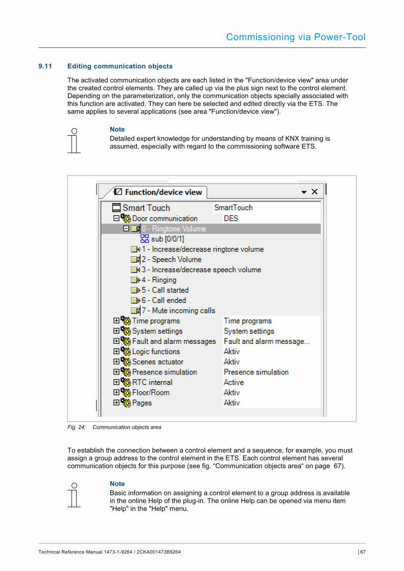
Commissioning via Power-Tool
Technical Reference Manual 1473-1-9264 / 2CKA001473B9264 │67
9.11 Editing communication objects
The activated communication objects are each listed in the "Function/device view" area under the created control elements. They are called up via the plus sign next to the control element. Depending on the parameterization, only the communication objects specially associated with this function are activated. They can here be selected and edited directly via the ETS. The same applies to several applications (see area "Function/device view").
Note Detailed expert knowledge for understanding by means of KNX training is assumed, especially with regard to the commissioning software ETS.
Fig. 24: Communication objects area
To establish the connection between a control element and a sequence, for example, you must assign a group address to the control element in the ETS. Each control element has several communication objects for this purpose (see fig. “Communication objects area“ on page 67).
Note Basic information on assigning a control element to a group address is available in the online Help of the plug-in. The online Help can be opened via menu item "Help" in the "Help" menu.
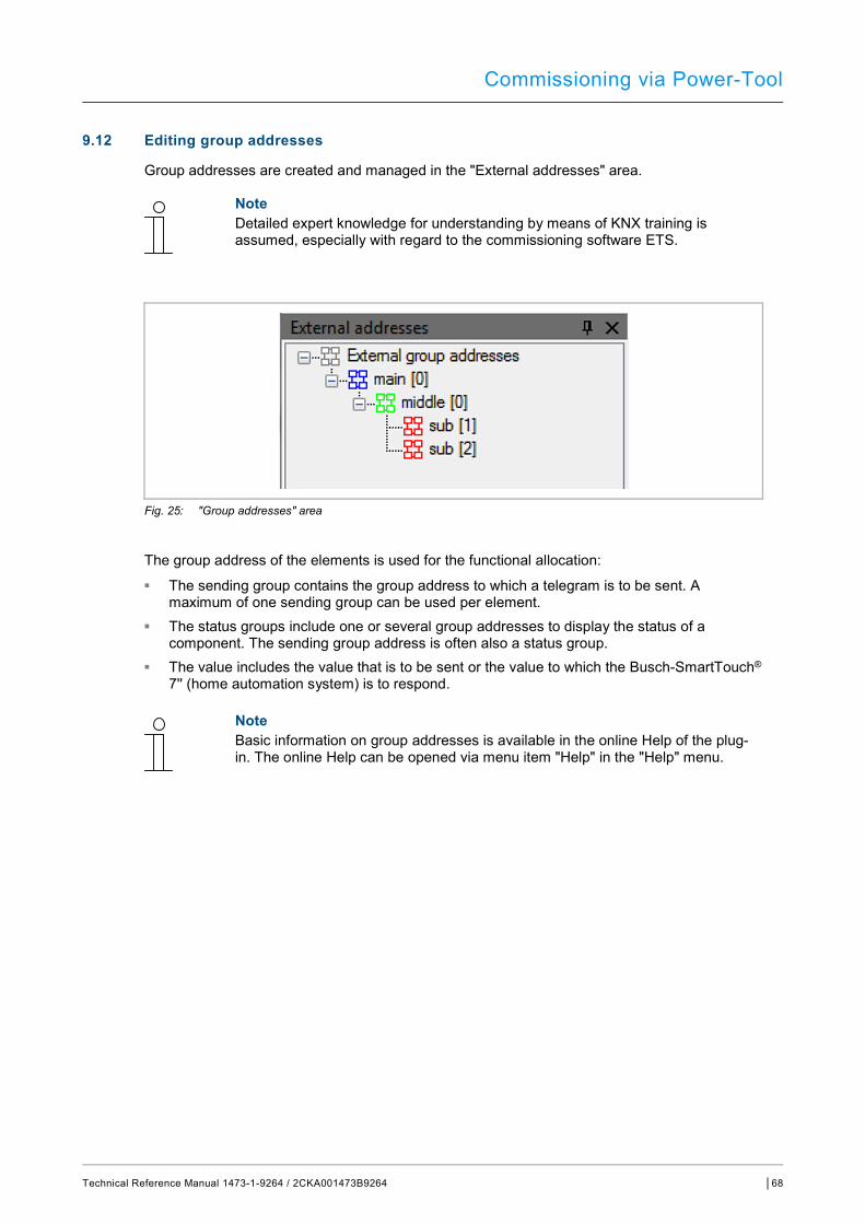
Commissioning via Power-Tool
Technical Reference Manual 1473-1-9264 / 2CKA001473B9264 │68
9.12 Editing group addresses
Group addresses are created and managed in the "External addresses" area.
Note Detailed expert knowledge for understanding by means of KNX training is assumed, especially with regard to the commissioning software ETS.
Fig. 25: "Group addresses" area
The group address of the elements is used for the functional allocation: ■ The sending group contains the group address to which a telegram is to be sent. A
maximum of one sending group can be used per element. ■ The status groups include one or several group addresses to display the status of a
component. The sending group address is often also a status group. ■ The value includes the value that is to be sent or the value to which the Busch-SmartTouch®
7'' (home automation system) is to respond.
Note Basic information on group addresses is available in the online Help of the plug-in. The online Help can be opened via menu item "Help" in the "Help" menu.

Commissioning via Power-Tool
Technical Reference Manual 1473-1-9264 / 2CKA001473B9264 │69
9.13 Additional tools (functions)
You can call up additional tools or functions of the Power-Tool via the menu bar or icon bar.
9.13.1 Programming (exporting)
1. Click on "Commissioning" in the Power-Tool menu bar. 2. Click on "Programming".
– A dialogue window opens with the following entries:
...via multi-media card This function is used to create an image file (*.pid).
1. Select the target directory in the dialogue window. 2. Assign a name. 3. Click on "Save".
Note The image file can be stored on a micro SD card (SDHC) and in this way transferred to the panel.
...via the bus
Note When selecting this function, you will be returned to the ETS to program the panel there.
9.13.2 Preview
With this function, you can test to see how project planning would look on a real panel. This allows you to test whether the project has been parameterized as desired before you create an image file. The call-up is made via the icon bar.
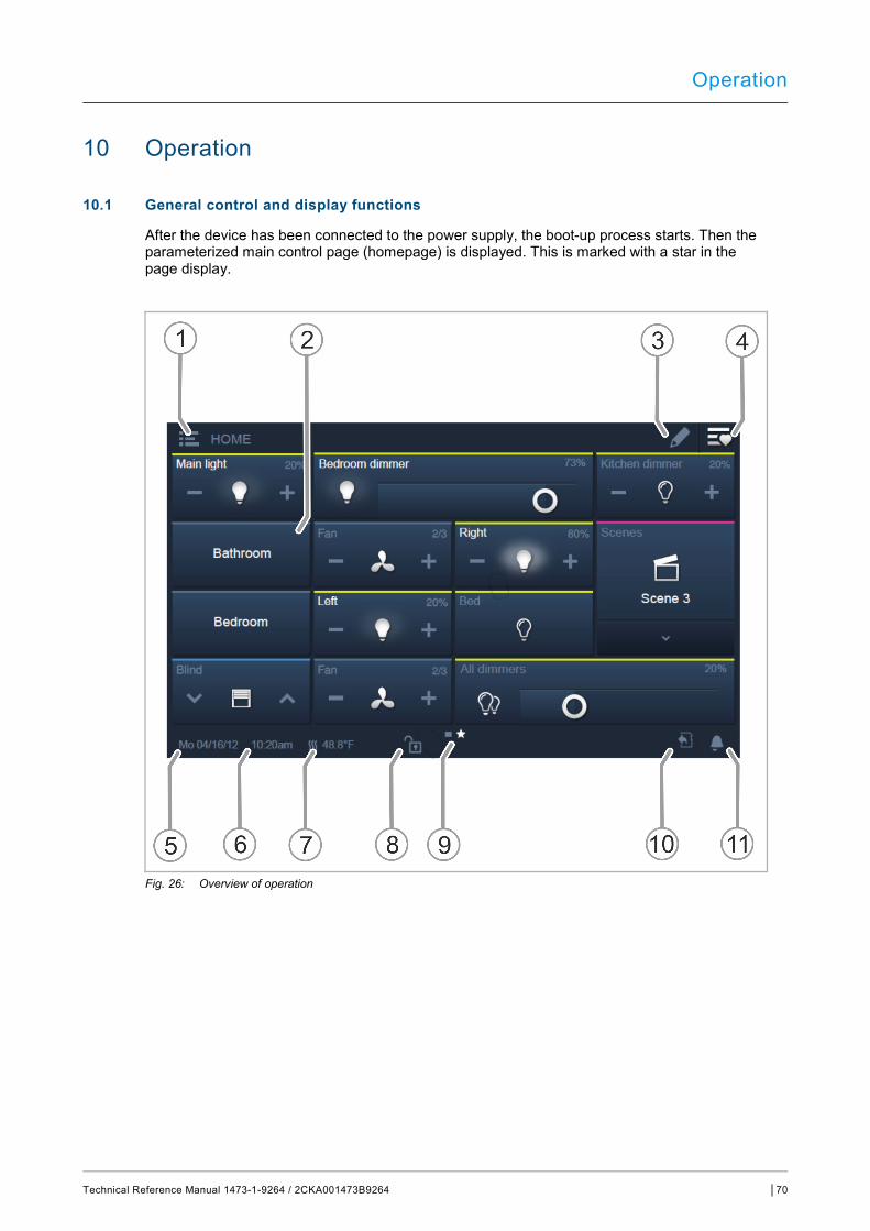
Operation
Technical Reference Manual 1473-1-9264 / 2CKA001473B9264 │70
10 Operation
10.1 General control and display functions
After the device has been connected to the power supply, the boot-up process starts. Then the parameterized main control page (homepage) is displayed. This is marked with a star in the page display.
Fig. 26: Overview of operation
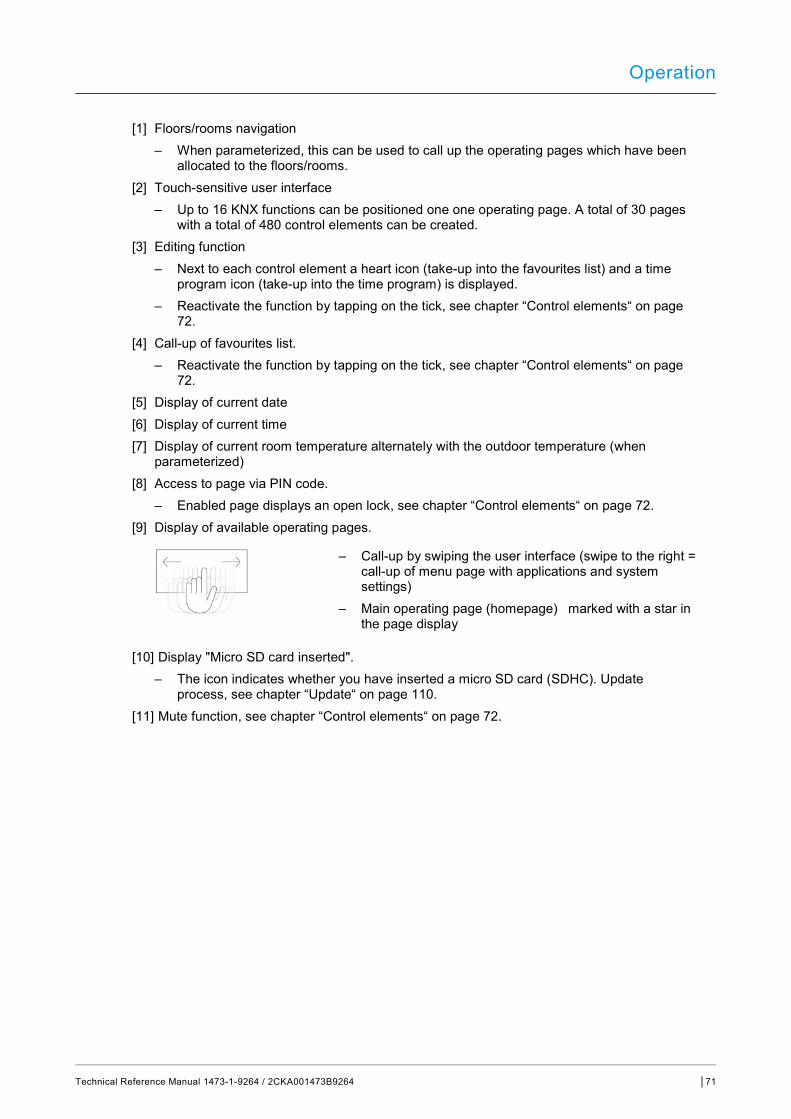
Operation
Technical Reference Manual 1473-1-9264 / 2CKA001473B9264 │71
[1] Floors/rooms navigation – When parameterized, this can be used to call up the operating pages which have been
allocated to the floors/rooms. [2] Touch-sensitive user interface
– Up to 16 KNX functions can be positioned one one operating page. A total of 30 pages with a total of 480 control elements can be created.
[3] Editing function – Next to each control element a heart icon (take-up into the favourites list) and a time
program icon (take-up into the time program) is displayed. – Reactivate the function by tapping on the tick, see chapter “Control elements“ on page
72. [4] Call-up of favourites list.
– Reactivate the function by tapping on the tick, see chapter “Control elements“ on page 72.
[5] Display of current date [6] Display of current time [7] Display of current room temperature alternately with the outdoor temperature (when
parameterized) [8] Access to page via PIN code.
– Enabled page displays an open lock, see chapter “Control elements“ on page 72. [9] Display of available operating pages.
– Call-up by swiping the user interface (swipe to the right = call-up of menu page with applications and system settings)
– Main operating page (homepage) marked with a star in the page display
[10] Display "Micro SD card inserted". – The icon indicates whether you have inserted a micro SD card (SDHC). Update
process, see chapter “Update“ on page 110. [11] Mute function, see chapter “Control elements“ on page 72.
Operation
Technical Reference Manual 1473-1-9264 / 2CKA001473B9264 │72
10.2 Control elements
Control elements in the Busch-SmartTouch® 7'' are used for fulfilling the basic functions of "Switching", "Dimming", "Blind", "Scenes" and "RTC". The elements can contain switches, buttons and sliders.
Available are:
Button operation Execution of function with a single press
Tapping operation Execution of function by pressing and holding
Control operation Shifting of a slider
Note Additional functions can be called up within some control elements (e.g. RTC) by swiping.
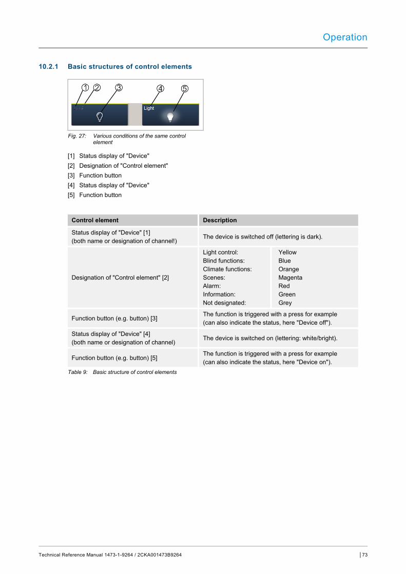
Operation
Technical Reference Manual 1473-1-9264 / 2CKA001473B9264 │73
10.2.1 Basic structures of control elements
Fig. 27: Various conditions of the same control element
[1] Status display of "Device" [2] Designation of "Control element" [3] Function button [4] Status display of "Device" [5] Function button
Control element Description
Status display of "Device" [1] (both name or designation of channel!)
The device is switched off (lettering is dark).
Designation of "Control element" [2]
Light control: Blind functions: Climate functions: Scenes: Alarm: Information: Not designated:
Yellow Blue Orange Magenta Red Green Grey
Function button (e.g. button) [3] The function is triggered with a press for example (can also indicate the status, here "Device off").
Status display of "Device" [4] (both name or designation of channel) The device is switched on (lettering: white/bright).
Function button (e.g. button) [5] The function is triggered with a press for example (can also indicate the status, here "Device on").
Table 9: Basic structure of control elements

Operation
Technical Reference Manual 1473-1-9264 / 2CKA001473B9264 │74
10.2.2 Additional basic principles
Function buttons of dimming control elements can display different stages of dimming by means of alternating icons (e.g. larger light halo around the icon).
Fig. 28: Basic principles
Presets of steps or levels (e.g. dimming steps, fan speed levels) are displayed in white/bright lettering/icons. In the following example the dimming step is preset at "20%). Fig. 29: Basic principles
Active elements or functions are displayed in white/bright lettering/icons.

Operation
Technical Reference Manual 1473-1-9264 / 2CKA001473B9264 │75
10.2.3 Adjustable control elements
Note The basic versions described here can be further adjusted.
Push-buttons (basic version) Simple switches can be implemented with push-buttons. This makes light switches or switches for simple switching processes based on push-buttons possible.
Control element Status Function
Switch
When operated, a changeover push-button sends out one of two values alternately and changes between two statuses (e.g. "On" and "Off").
Rocker switch
A neutral push-button with rocker function when actuated on the right or left side of the rocker sends out a switching telegram. A differentiation is made between whether the rocker is actuated on the left or on the right side. This allows one of two versions of a function to be selected. The two bottom icons represent the function of the rocker switch. A neutral push-button with rocker function can be used to call up two different scenes for example (in the example: "Presence" or "Absence").

Operation
Technical Reference Manual 1473-1-9264 / 2CKA001473B9264 │76
Dimmer (basic version can be further adjusted, e.g. with value display) Dimmers can be used to implement convenient light switches with dimming functions.
Control element Status Function
Dimmer without slider
The version without slider has a push-button surface for switching On/Off in the middle and via two buttons left and right for stepwise dimming (brighter/darker).
Dimmer with slider
The version with slider has a push-button surface for switching On/Off in the left side and via a slider for dimming.
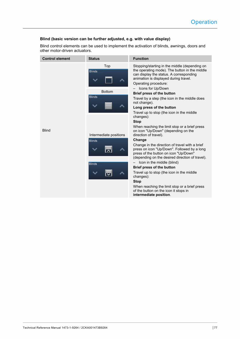
Operation
Technical Reference Manual 1473-1-9264 / 2CKA001473B9264 │77
Blind (basic version can be further adjusted, e.g. with value display) Blind control elements can be used to implement the activation of blinds, awnings, doors and other motor-driven actuators.
Control element Status Function
Blind
Top Stopping/starting in the middle (depending on the operating mode). The button in the middle can display the status. A corresponding animation is displayed during travel. Operating procedure: – Icons for Up/Down Brief press of the button Travel by a step (the icon in the middle does not change). Long press of the button Travel up to stop (the icon in the middle changes): Stop When reaching the limit stop or a brief press on icon "Up/Down" (depending on the direction of travel). Change Change in the direction of travel with a brief press on icon "Up/Down". Followed by a long press of the button on icon "Up/Down" (depending on the desired direction of travel). – Icon in the middle (blind) Brief press of the button Travel up to stop (the icon in the middle changes): Stop When reaching the limit stop or a brief press of the button on the icon it stops in intermediate position.
Bottom
Intermediate positions
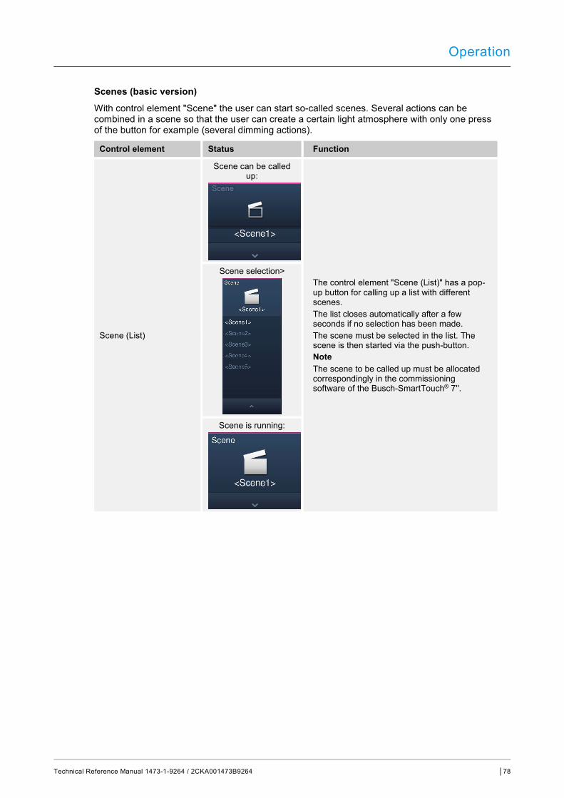
Operation
Technical Reference Manual 1473-1-9264 / 2CKA001473B9264 │78
Scenes (basic version) With control element "Scene" the user can start so-called scenes. Several actions can be combined in a scene so that the user can create a certain light atmosphere with only one press of the button for example (several dimming actions).
Control element Status Function
Scene (List)
Scene can be called up:
The control element "Scene (List)" has a pop-up button for calling up a list with different scenes. The list closes automatically after a few seconds if no selection has been made. The scene must be selected in the list. The scene is then started via the push-button. Note The scene to be called up must be allocated correspondingly in the commissioning software of the Busch-SmartTouch® 7''.
Scene selection>
Scene is running:
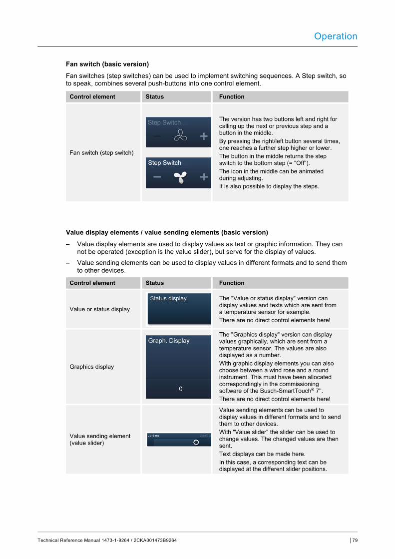
Operation
Technical Reference Manual 1473-1-9264 / 2CKA001473B9264 │79
Fan switch (basic version) Fan switches (step switches) can be used to implement switching sequences. A Step switch, so to speak, combines several push-buttons into one control element.
Control element Status Function
Fan switch (step switch)
The version has two buttons left and right for calling up the next or previous step and a button in the middle. By pressing the right/left button several times, one reaches a further step higher or lower. The button in the middle returns the step switch to the bottom step (= "Off"). The icon in the middle can be animated during adjusting. It is also possible to display the steps.
Value display elements / value sending elements (basic version) – Value display elements are used to display values as text or graphic information. They can
not be operated (exception is the value slider), but serve for the display of values. – Value sending elements can be used to display values in different formats and to send them
to other devices.
Control element Status Function
Value or status display
The "Value or status display" version can display values and texts which are sent from a temperature sensor for example. There are no direct control elements here!
Graphics display
The "Graphics display" version can display values graphically, which are sent from a temperature sensor. The values are also displayed as a number. With graphic display elements you can also choose between a wind rose and a round instrument. This must have been allocated correspondingly in the commissioning software of the Busch-SmartTouch® 7''. There are no direct control elements here!
Value sending element (value slider)
Value sending elements can be used to display values in different formats and to send them to other devices. With "Value slider" the slider can be used to change values. The changed values are then sent. Text displays can be made here. In this case, a corresponding text can be displayed at the different slider positions.
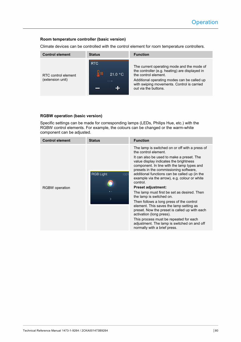
Operation
Technical Reference Manual 1473-1-9264 / 2CKA001473B9264 │80
Room temperature controller (basic version) Climate devices can be controlled with the control element for room temperature controllers.
Control element Status Function
RTC control element (extension unit)
The current operating mode and the mode of the controller (e.g. heating) are displayed in the control element. Additional operating modes can be called up with swiping movements. Control is carried out via the buttons.
RGBW operation (basic version) Specific settings can be made for corresponding lamps (LEDs, Philips Hue, etc.) with the RGBW control elements. For example, the colours can be changed or the warm-white component can be adjusted.
Control element Status Function
RGBW operation
The lamp is switched on or off with a press of the control element. It can also be used to make a preset. The value display indicates the brightness component. In line with the lamp types and presets in the commissioning software, additional functions can be called up (in the example via the arrow), e.g. colour or white control. Preset adjustment: The lamp must first be set as desired. Then the lamp is switched on. Then follows a long press of the control element. This saves the lamp setting as preset. Now the preset is called up with each activation (long press). This process must be repeated for each adjustment. The lamp is switched on and off normally with a brief press.

Operation
Technical Reference Manual 1473-1-9264 / 2CKA001473B9264 │81
Audio control (basic version) All audio settings for connected audio devices can be easily controlled with the aid of this control element.
Control element Status Function
Audio control
Corresponding to the presets in the commissioning software, a variety of audio functions can be called up directly via the buttons. Lists can be opened via the arrow buttons.
Page link (basic version) Here a link can be directly established on a created page. This opens it.
Control element Status Function
Page link The link is used to call up available pages directly in the Busch-SmartTouch® 7''.

Operation
Technical Reference Manual 1473-1-9264 / 2CKA001473B9264 │82
10.3 Special functions
10.3.1 Editing
The "Edit" function can only be called up via the main operating page and the operating pages.
1. It is opened via this icon.
Fig. 30: Edit icon
– Next to each control element a heart icon (take-up into the favourites list) and a time program icon (take-up into the time program) is displayed.
Take-up into the favourites list: 1. Tap on a heart icon next to a control element which is to be taken up into the favourites list. 2. The heart icon now appears filled in, which means that the control element has been taken
up into the favourites list.
Take-up into time programs: 1. Tap on a time program icon next to a control element which is to become part of a time
program. – The window "Create new timer" opens.
2. Specify weekdays during which the function of the control element is to be carried out. To do this, tap on the days. – A renewed tap removes the day!
3. Specify the starting time. Use the scrolling element for this. – An end time can be additionally activated. For this the time can also be set via the
scrolling element. 4. Activate the astro function (option). – This function can be used, for example, to automatically raise or lower the blinds a few
minutes earlier or later depending on the time of year. – The disabling function "Not before" and "Not after" fixes disabling times before or after which
no functions are carried out. For this the time can also be set via the scrolling element.
Note The correct coordinates of the device location must be set. The coordinates are entered via the system settings of the commissioning tool.
5. Tap on "Create". – The time program is then taken up into the time program list and can be edited there.
(see chapter “Time programs“ on page 94). 6. Finally tap on "OK".
– A time program icon appears next to the control element with a digit (number of created time programs with this control element).
7. The "Edit" function can be closed by tapping on the tick in the top bar.

Operation
Technical Reference Manual 1473-1-9264 / 2CKA001473B9264 │83
10.3.2 Call-up and editing of the favourites list
The favourites are, for example, actuators that are frequently used. These can then be switched directly via the favourites list, without the rooms having to be called up for example. The take-up of the elements into the favourites list is carried out either via the commissioning software or directly via the device (see chapter “Editing“ on page 82). Also time programs can be taken up (see chapter “Time programs“ on page 94)!
Operation via the favourites list: The "Favourites list" function can only be called up via the main operating page (homepage) and the operating pages.
1. The "Favourites list" function is opened via this icon.
Fig. 31: Favourites list icon
2. Select either the time program icon or the lamp icon, depending on whether the favourites of the time program or the control elements are to be listed.
3. Carry out the functions of a control element directly in the list or activate a time program.
Editing the favourites list: The "Favourites list" function can only be called up via the main operating page (homepage) and the operating pages.
1. The "Favourites list" function is opened via this icon.
Fig. 32: Favourites list icon
The elements of the favourites list can be deleted.
2. To do this, click on the icon in the top bar.
Fig. 33: Edit icon
3. Tap on the respective dustbin icon appearing next to the elements.
Fig. 34: Favourites list icon
– The element is deleted from the list. 4. The "Favourites list" function can be closed by tapping on the cross in the top bar.
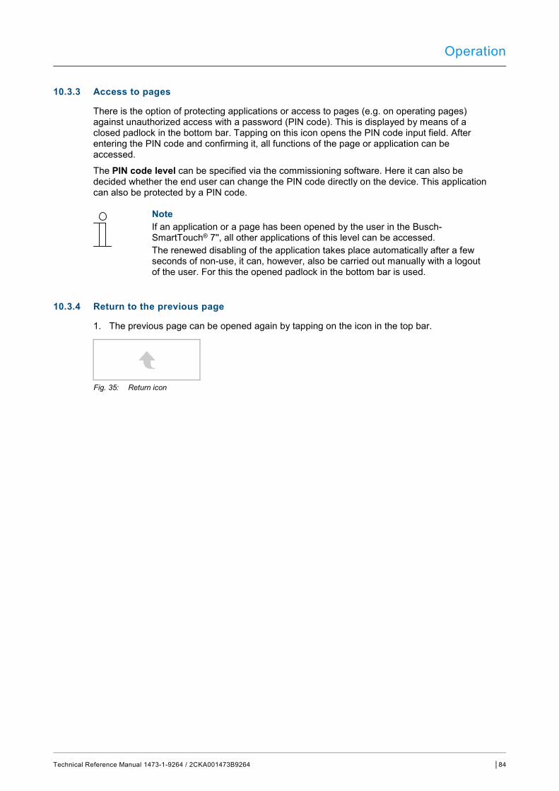
Operation
Technical Reference Manual 1473-1-9264 / 2CKA001473B9264 │84
10.3.3 Access to pages
There is the option of protecting applications or access to pages (e.g. on operating pages) against unauthorized access with a password (PIN code). This is displayed by means of a closed padlock in the bottom bar. Tapping on this icon opens the PIN code input field. After entering the PIN code and confirming it, all functions of the page or application can be accessed.
The PIN code level can be specified via the commissioning software. Here it can also be decided whether the end user can change the PIN code directly on the device. This application can also be protected by a PIN code.
Note If an application or a page has been opened by the user in the Busch-SmartTouch® 7'', all other applications of this level can be accessed. The renewed disabling of the application takes place automatically after a few seconds of non-use, it can, however, also be carried out manually with a logout of the user. For this the opened padlock in the bottom bar is used.
10.3.4 Return to the previous page
1. The previous page can be opened again by tapping on the icon in the top bar.
Fig. 35: Return icon
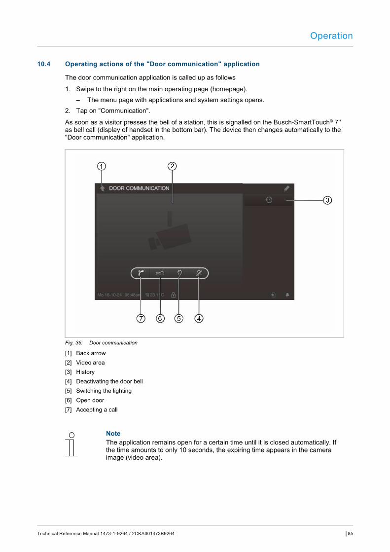
Operation
Technical Reference Manual 1473-1-9264 / 2CKA001473B9264 │85
10.4 Operating actions of the "Door communication" application
The door communication application is called up as follows
1. Swipe to the right on the main operating page (homepage). – The menu page with applications and system settings opens.
2. Tap on "Communication".
As soon as a visitor presses the bell of a station, this is signalled on the Busch-SmartTouch® 7'' as bell call (display of handset in the bottom bar). The device then changes automatically to the "Door communication" application.
Fig. 36: Door communication
[1] Back arrow [2] Video area [3] History [4] Deactivating the door bell [5] Switching the lighting [6] Open door [7] Accepting a call
Note The application remains open for a certain time until it is closed automatically. If the time amounts to only 10 seconds, the expiring time appears in the camera image (video area).

Operation
Technical Reference Manual 1473-1-9264 / 2CKA001473B9264 │86
10.4.1 Establishing a speech and video connection
1. The function is called up via the receiver button.
Fig. 37: Receiver button
The following functions are available while establishing the speech and video connection.
Function: ■Setting the volume by tapping the corresponding buttons (plus and minus).
If several outdoor stations or external cameras are connected: ■ Select the camera from the list by tapping the arrow button.
– The designation of the camera is then displayed. – The current picture of the camera appears in the video area.
2. The connection can be terminated by pressing the button.
Fig. 38: Replacing the receiver button
10.4.2 Opening the door
1. The function is called up via the key button.
Fig. 39: Key button
Actuating the door opener makes the following function available.
Function: ■ Door operner is actuated or the "Automatic door opener" is active.
– A white key" icon is displayed. – The door opener is now switched on.
Operation
Technical Reference Manual 1473-1-9264 / 2CKA001473B9264 │87
10.4.3 Activating mute (mite timer)
1. The function is called up via the bell button.
Fig. 40: Bell button
For mute activation (mute timer) the following functions are available.
Function No call is pending: ■ "Mute" button (bell icon) is actuated.
– The ring tone of the panel is deactivated for a certain time. This is also indicated as icon in the bottom bar.
– If calls are received during this time, only the video image is displayed. – Missed calls are recorded in the events and image storage. – The presets for this can be adjusted.
A call is pending, a speech connection is activated. ■ "Mute" button (microphone icon) is actuated.
– The microphone of the device is switched off until the bell is pressed again.
Note The mute timer (settings) can also be called up via the push-button (bell icon) in the bottom bar.
10.4.4 Switching light
1. The function is called up via the lamp button.
Fig. 41: Lamp button
Actuating the light switch makes the following function available:
Function ■ "Switching light" button actuated.
– The "White lamp" icon is displayed. – The lamp of the outdoor station is switched.
Operation
Technical Reference Manual 1473-1-9264 / 2CKA001473B9264 │88
10.4.5 Events and image storage / history
The device records all events. When actuating the "History" button the last 100 events are displayed (previous events are overwritten).
1. The function is called up via the history button.
Fig. 42: History
Function
■ The "Auto snapshots" function is activated in the settings for the door communication. – The flashing icon in the bottom bar signals a newly recorded snapshot. – The icon stops flashing when you call up the events and image storage.
Note When a speech connection is activated, a snapshot can be created at any time by pressing the history button, even if the "Auto snapshot" function is not active. – The history button is only visible when the full-screen is reduced.
■ For function "Events and image storage / history" the following functions are available:
– When the "Auto snapshots" function is activated in the settings for the door communication, a miniature view is displayed in the events list for missed calls.
– Date, time and the type of the event are recorded together with the snapshot. – If no automatic snapshots are active, a camera icon is displayed in place of the
miniature view. – Individual entries or the entire list can be deleted at any time. For this, tap on the pen
icon. A dustbin icon appears net to the entry. This can be used to delete every single entry. Or all entries can be delted via "Delete all".
– Select an event by tapping on the corresponding entry. – Select single recordings by tapping on the corresponding entry. The list can be scrolled.

Operation
Technical Reference Manual 1473-1-9264 / 2CKA001473B9264 │89
10.5 Control actions of additional applications
10.5.1 Presence simulation
The absence of the residents in a building can be fairly realistically simulated via the presence simulation, to increase the protection against unauthorized access. For this purpose the Busch-SmartTouch® 7'' specifically records all actions for up to 20 objects every minute of the whole day (up to 0 o'clock) and can then replay them again.
Note – Please note that you must always create a presence simulation beforehand,
so that the simulation can be played back later! – For this the device must have been active once for at least one day (up to 0
o'clock) and have recorded telegrams (per minute). Otherwise the message that no data are available is displayed at the start of the application.
– The application always uses the telegrams of the previous day. If no data are available on the previous day, the data of days before the previous day are used.
The presence simulation application is called up as follows:
1. Swipe to the right on the main operating page (homepage). – The application page with applications and system settings opens.
2. Tap on "Timer".
3. Select presence simulation in the list.
This starts the application. The icon for the activated presence simulation is displayed.
The presence simulation application is deactivated up as follows:
1. Tap on the activated presence simulation in the list.
Operation
Technical Reference Manual 1473-1-9264 / 2CKA001473B9264 │90
Importing presence simulation into the favourites list (via timer list): 1. Tap on the pen icon.
2. Tap on the heart icon next to the presence simulation in the list.
– The heart icon is now displayed filled in.
The presence simulation has been imported into the favourites list. Here it can be activated and deactivated.
Exporting presence simulation to micro SD card (via timer list): 1. Tap on the pen icon.
2. Insert the micro SD card into the device (see chapter “Inserting the micro SD card (SDHC)“ on page 98).
3. Tap on the card icon next to the presence simulation in the list.
– The presence simulation is exported to the micro SD card in CSV format. – Via the data it can be determined whether the telegrams have been recorded.
Operation
Technical Reference Manual 1473-1-9264 / 2CKA001473B9264 │91
10.5.2 Fault and alarm messages
The Busch-SmartTouch® 7'' offers protection and information during malfunctions or faults. Message contacts, sensors and their functionality can be monitored. The messages desired in case of a fault or an alarm can be set individually (see chapter 9.10.2 “Application "Fault and alarm messages"“ on page 64).
Note Depending on the parameterization, only certain functions are available in the application.
This allows the user to see via the "Fault and alarm messages" which messages have appeared in the Busch-SmartTouch® 7''. This application can also be used to acknowledge, export and delete the messages.
The "Fault and alarm messages" application is called up as follows:
1. Swipe to the right on the main operating page (homepage). – The application page with applications and system settings opens.
2. Tap on "Alarm".
Here the current and archived messages (notifications) can be displayed and edited.
Confirming and archiving messages (notifications): 1. Tap on the pen icon.
2. Then tap on a message in the list. – The message can now be confirmed. – Depending on the parameterization, the message is now automatically archived or it can
be archived manually.
Operation
Technical Reference Manual 1473-1-9264 / 2CKA001473B9264 │92
Exporting messages (notifications) to the micro SD card: Confirmed and archived messages can be exported.
1. Confirming messages. 2. Tap on the archive icon.
3. Then tap on the pen icon.
4. Select the message to be copied from the list. 5. Insert the micro SD card into the device (see chapter “Inserting the micro SD card (SDHC)“
on page 98). 6. Then tap on "Copy to SD card".
Note The export function must have been parameterized!
Operation
Technical Reference Manual 1473-1-9264 / 2CKA001473B9264 │93
Deleting messages (notifications):
Note Only archived messages can be deleted.
1. Tap on the pen icon.
2. Select the message to be deleted from the list. 3. Tap on the adjacent dustbin icon.
– The message is deleted.
Deleting archived messages (notifications): 1. Tap on the archive icon.
2. Then tap on the pen icon.
3. Select the message to be deleted from the list. 4. Tap on the adjacent dustbin icon.
– The message is deleted.
Note Also the entire list can be deleted. ■ For this, tap on "Delete all".

Operation
Technical Reference Manual 1473-1-9264 / 2CKA001473B9264 │94
10.5.3 Time programs
Time programs can be used call up functions according to the time automatically. This allows the holiday function to be started and set up.
The time programs application is called up as follows: ■ Swipe to the right on the main operating page (homepage).
– The application page with applications and system settings opens. ■ Tap on "Timer".
– Here corresponding time programs can be programmed.
Fig. 43: Time programs

Operation
Technical Reference Manual 1473-1-9264 / 2CKA001473B9264 │95
Creating a new time program: 1. Tap on the pen icon.
2. Then tap on this icon. – The main operating page (homepage) opens. – Now the time program icon appears next to every control element.
Note You can also call up every other page.
3. Tap on a time program icon next to a control element which is to become a component part of a time program. – The window "Create new timer" opens.
4. Specify weekdays during which the function of the control element is to be carried out. To do this, tap on the days. – A renewed tap removes the day!
5. Specify the starting time. Use the scrolling element for this. – An end time can be additionally activated for some control elements. For this the time
can also be set via the scrolling element. 6. Activate the optional astro function.
– This function can be used, for example, to automatically raise or lower the blinds a few minutes earlier or later depending on the time of year.
– The disabling function "Not before" and "Not after" fixes disabling times before or after which no functions are carried out. For this the time can also be set via the scrolling element.
Note The correct coordinates of the device location must be set for the astro function. – This is carried out via the system settings of the commissioning tool.
7. Tap on "Create". – The time program is then taken up into the time program list and can be edited there.
8. Finally tap on "OK". – A time program icon appears next to the control element with a digit (number of created
time programs with this control element).
Note For this, however, one must tap on the pen icon on the operating page.
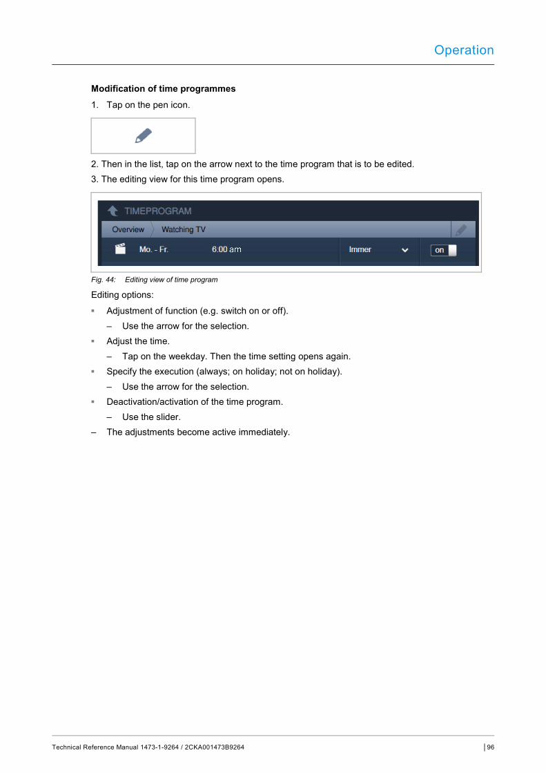
Operation
Technical Reference Manual 1473-1-9264 / 2CKA001473B9264 │96
Modification of time programmes 1. Tap on the pen icon.
2. Then in the list, tap on the arrow next to the time program that is to be edited. 3. The editing view for this time program opens.
Fig. 44: Editing view of time program
Editing options: ■ Adjustment of function (e.g. switch on or off).
– Use the arrow for the selection. ■ Adjust the time.
– Tap on the weekday. Then the time setting opens again. ■ Specify the execution (always; on holiday; not on holiday).
– Use the arrow for the selection. ■ Deactivation/activation of the time program.
– Use the slider. – The adjustments become active immediately.
Operation
Technical Reference Manual 1473-1-9264 / 2CKA001473B9264 │97
Importing time programs into the favourites list 1. Tap on the pen icon.
2. Then in the list, tap on the heart icon next to the time program which is to be taken up into the favourites list. – The heart icon is now displayed filled in. – The time program has been imported into the favourites list.
Deleting time programs 1. Tap on the pen icon.
2. Then in the list, tap on the dustbin icon next to the time program which is to be deleted. 3. Confirm the displayed message.
Setup of holiday function 1. Tap on the "i" icon next to entry "Holiday".
– The window "Set holiday" opens. 2. Specify the start and the end of the holiday. Use the scrolling element for this. 3. Tap on OK.
– The overview list with the updated holiday entry is displayed. 4. Tap on the "Holiday" entry.
– The lettering turns white. The holiday function is now activated. – Now the editing function of the individual time programs can be used to specify the time
programs that are to run during the holiday.
Note The holiday function is deactivated by tapping on the activated entry.
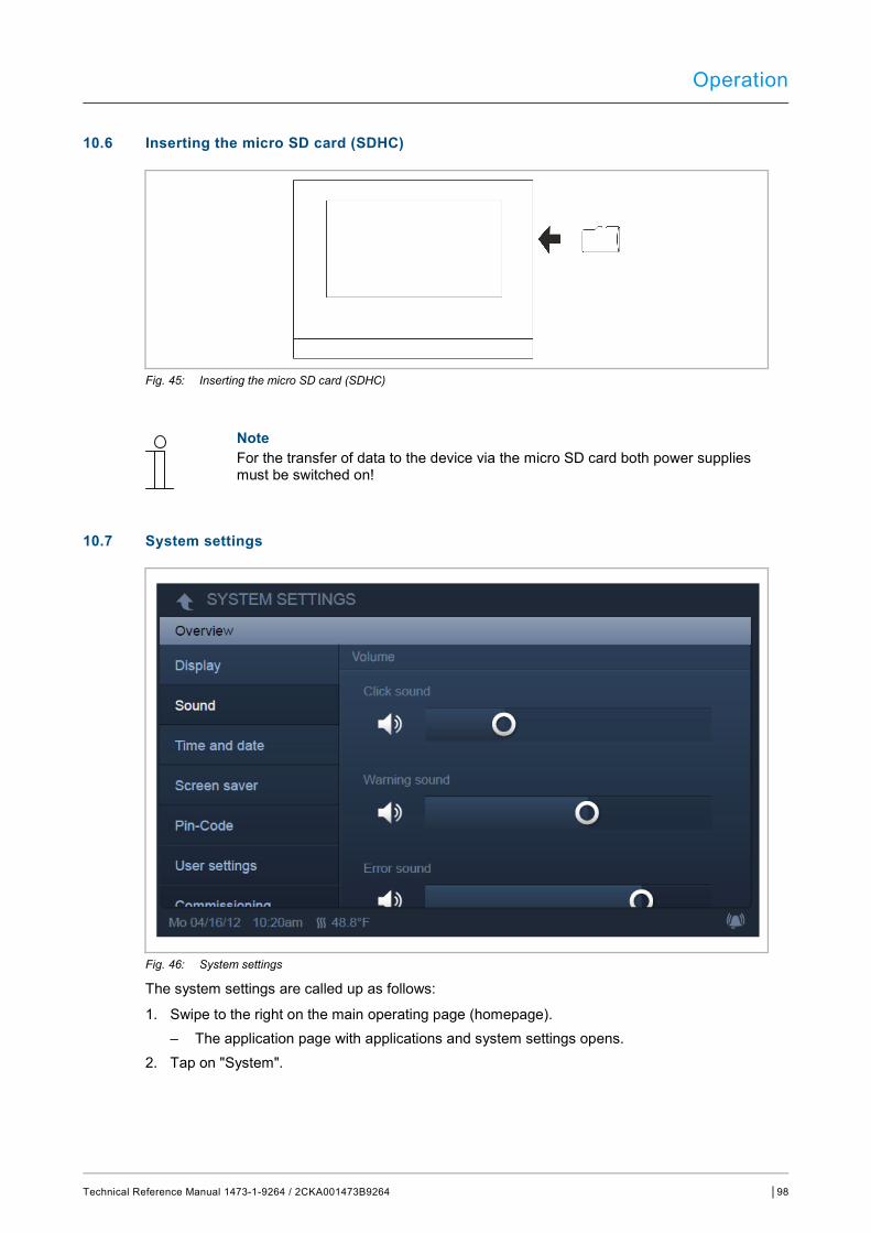
Operation
Technical Reference Manual 1473-1-9264 / 2CKA001473B9264 │98
10.6 Inserting the micro SD card (SDHC)
Fig. 45: Inserting the micro SD card (SDHC)
Note For the transfer of data to the device via the micro SD card both power supplies must be switched on!
10.7 System settings
Fig. 46: System settings
The system settings are called up as follows:
1. Swipe to the right on the main operating page (homepage). – The application page with applications and system settings opens.
2. Tap on "System".
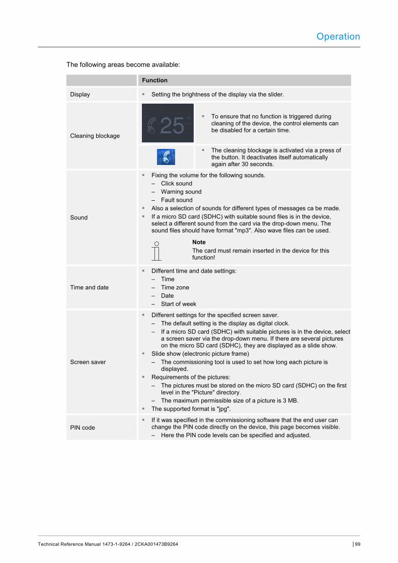
Operation
Technical Reference Manual 1473-1-9264 / 2CKA001473B9264 │99
The following areas become available:
Function
Display ■ Setting the brightness of the display via the slider.
Cleaning blockage
■ To ensure that no function is triggered during cleaning of the device, the control elements can be disabled for a certain time.
■ The cleaning blockage is activated via a press of the button. It deactivates itself automatically again after 30 seconds.
Sound
■ Fixing the volume for the following sounds. – Click sound – Warning sound – Fault sound
■ Also a selection of sounds for different types of messages ca be made. ■ If a micro SD card (SDHC) with suitable sound files is in the device,
select a different sound from the card via the drop-down menu. The sound files should have format "mp3". Also wave files can be used.
Note The card must remain inserted in the device for this function!
Time and date
■ Different time and date settings: – Time – Time zone – Date – Start of week
Screen saver
■ Different settings for the specified screen saver. – The default setting is the display as digital clock. – If a micro SD card (SDHC) with suitable pictures is in the device, select
a screen saver via the drop-down menu. If there are several pictures on the micro SD card (SDHC), they are displayed as a slide show.
■ Slide show (electronic picture frame) – The commissioning tool is used to set how long each picture is
displayed. ■ Requirements of the pictures:
– The pictures must be stored on the micro SD card (SDHC) on the first level in the "Picture" directory.
– The maximum permissible size of a picture is 3 MB. ■ The supported format is "jpg".
PIN code ■ If it was specified in the commissioning software that the end user can
change the PIN code directly on the device, this page becomes visible. – Here the PIN code levels can be specified and adjusted.

Operation
Technical Reference Manual 1473-1-9264 / 2CKA001473B9264 │100
User settings
■ Here the following settings can be made: – Language – Display of separator – Unit of temperature display
Commissioning
■ Here different commissioning processes can be started: – Programming mode: Here the device is set into programming mode. At
the same time a physical address is assigned to the device and transferred to the ETS. The programming mode is deactivated again by tapping on the red "Programming mode" button.
– Reset: Here a reset is made to the start settings of the device since the last start.
– Read SD card (start the read process when the micro SD card is inserted): A PID file can be selected from the list. The file is transferred to the device by confirming the message.
– Firmware update (start the read process when the micro SD card is inserted): A Firmware file (*.img) can be selected from the list. The file is transferred to the device by confirming the message.
Information
■ Here different information about the device is displayed, such as the KNX address or the Firmware version. Also an error log can be exported here.
Create error log process: 1. Insert the micro SD card. 2. Tap on the "Export error log" button. 3. Confirm message about the successful export. 4. Remove the micro SD card. 5. Read card into the PC. Use an adapter if necessary. 6. Send the log file (*.log) via e-mail (see rear page of the manual) to sales
service. Table 10: System areas
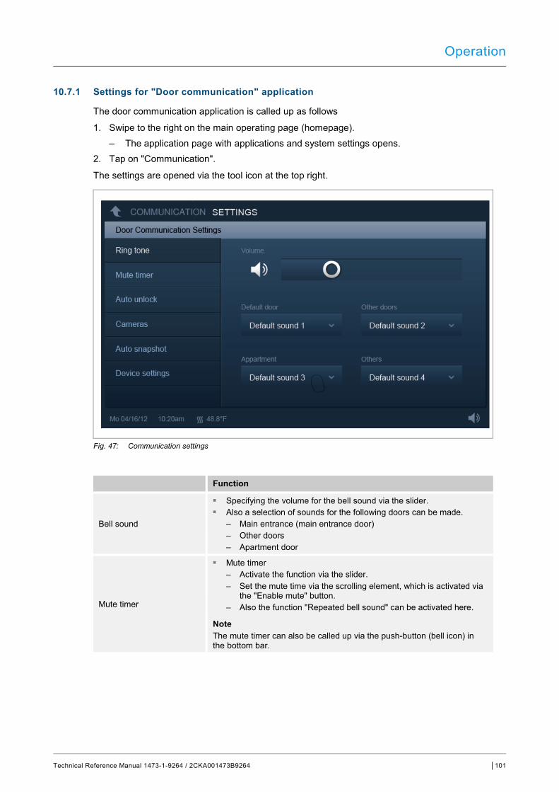
Operation
Technical Reference Manual 1473-1-9264 / 2CKA001473B9264 │101
10.7.1 Settings for "Door communication" application
The door communication application is called up as follows
1. Swipe to the right on the main operating page (homepage). – The application page with applications and system settings opens.
2. Tap on "Communication".
The settings are opened via the tool icon at the top right.
Fig. 47: Communication settings
Function
Bell sound
■ Specifying the volume for the bell sound via the slider. ■ Also a selection of sounds for the following doors can be made.
– Main entrance (main entrance door) – Other doors – Apartment door
Mute timer
■ Mute timer – Activate the function via the slider. – Set the mute time via the scrolling element, which is activated via
the "Enable mute" button. – Also the function "Repeated bell sound" can be activated here.
Note The mute timer can also be called up via the push-button (bell icon) in the bottom bar.
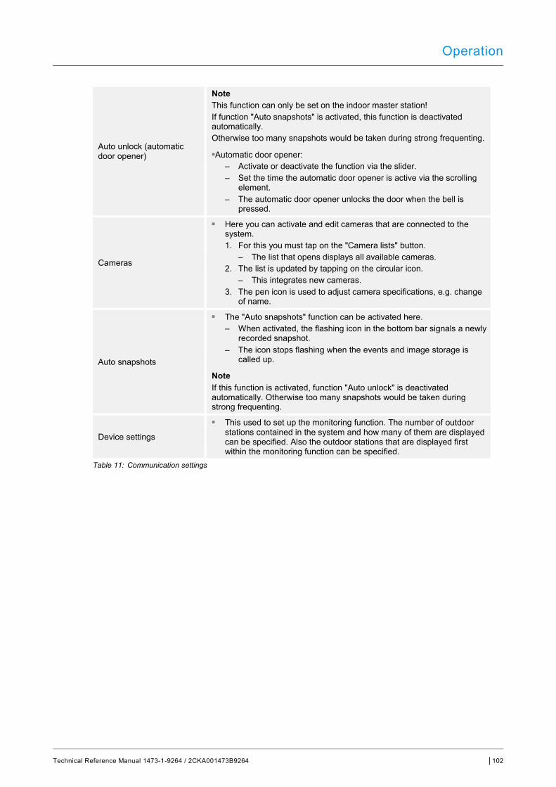
Operation
Technical Reference Manual 1473-1-9264 / 2CKA001473B9264 │102
Auto unlock (automatic door opener)
Note This function can only be set on the indoor master station! If function "Auto snapshots" is activated, this function is deactivated automatically. Otherwise too many snapshots would be taken during strong frequenting.
■Automatic door opener: – Activate or deactivate the function via the slider. – Set the time the automatic door opener is active via the scrolling
element. – The automatic door opener unlocks the door when the bell is
pressed.
Cameras
■ Here you can activate and edit cameras that are connected to the system. 1. For this you must tap on the "Camera lists" button.
– The list that opens displays all available cameras. 2. The list is updated by tapping on the circular icon.
– This integrates new cameras. 3. The pen icon is used to adjust camera specifications, e.g. change
of name.
Auto snapshots
■ The "Auto snapshots" function can be activated here. – When activated, the flashing icon in the bottom bar signals a newly
recorded snapshot. – The icon stops flashing when the events and image storage is
called up.
Note If this function is activated, function "Auto unlock" is deactivated automatically. Otherwise too many snapshots would be taken during strong frequenting.
Device settings
■ This used to set up the monitoring function. The number of outdoor stations contained in the system and how many of them are displayed can be specified. Also the outdoor stations that are displayed first within the monitoring function can be specified.
Table 11: Communication settings
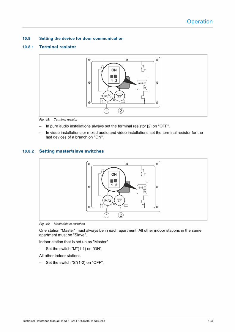
Operation
Technical Reference Manual 1473-1-9264 / 2CKA001473B9264 │103
10.8 Setting the device for door communication
10.8.1 Terminal resistor
Fig. 48: Terminal resistor
– In pure audio installations always set the terminal resistor [2] on "OFF". – In video installations or mixed audio and video installations set the terminal resistor for the
last devices of a branch on "ON".
10.8.2 Setting master/slave switches
Fig. 49: Master/slave switches
One station "Master" must always be in each apartment. All other indoor stations in the same apartment must be "Slave".
Indoor station that is set up as "Master"
– Set the switch "M"(1-1) on "ON".
All other indoor stations
– Set the switch "S"(1-2) on "OFF".
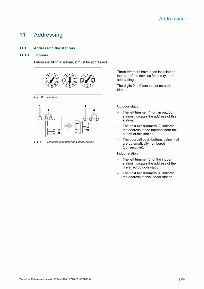
Addressing
Technical Reference Manual 1473-1-9264 / 2CKA001473B9264 │104
11 Addressing
11.1 Addressing the stations
11.1.1 Trimmer
Before installing a system, it must be addressed.
Three trimmers have been installed on the rear of the devices for this type of addressing.
The digits 0 to 9 can be set on each trimmer.
Fig. 50: Trimmer
Outdoor station:
– The left trimmer [1] on an outdoor station indicates the address of this station.
– The next two trimmers [2] indicate the address of the topmost door bell button of this station.
– The doorbell push-buttons below that are automatically numbered (consecutive).
Indoor station:
– The left trimmer [3] of the indoor station indicates the address of the preferred outdoor station.
– The next two trimmers [4] indicate the address of this indoor station.
Fig. 51: Trimmers of outdoor and indoor station

Addressing
Technical Reference Manual 1473-1-9264 / 2CKA001473B9264 │105
11.1.2 Setting the address of the outdoor station
The allocation to one of the four inputs of the system is made on the outdoor stations and the associated switch actuators for door and light via the setting of the address.
For this the house/outdoor potentiometer is set on an address between 1 and 4. The potentiometer is located on the rear of the outdoor station or on the front of the MDRC switch actuator.
11.1.3 Assigning the doorbell push-button of an outdoor station to an apartment
The doorbell push-buttons of an outdoor station are assigned to the apartments consecutively from top to bottom and left to right with the addresses 01, 02, etc.
This simple assignment also applies to several outdoor stations in a system. This means that in fig. “Several outdoor stations with identical assignment“ on page 108 the button A is assigned to apartment 01 in every outdoor station, etc.
This factory setting is fixed via two potentiometers on the rear of the outdoor station. The middle potentiometer must be on "0" and the right one on "1
11.1.4 Setting the address of the indoor station
At the indoor stations the apartment is assigned via the setting of the address. Up to 99 apartments can be addressed within one system. In each of these up to four indoor stations with the same rights can be located with the same address.
The four indoor stations are called when the assigned door bell button is pressed. The address of an indoor station (e.g. "15") is set with the aid of the potentiometers on the indoor station, while the middle one indicates the tens digit (here "1") and left one the ones digit (here "5"). The potentiomenter is located on the rear or exterior of the indoor station.
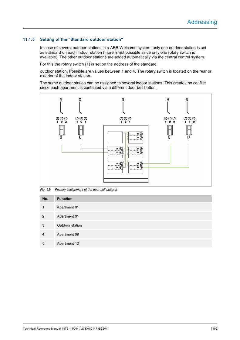
Addressing
Technical Reference Manual 1473-1-9264 / 2CKA001473B9264 │106
11.1.5 Setting of the "Standard outdoor station"
In case of several outdoor stations in a ABB-Welcome system, only one outdoor station is set as standard on each indoor station (more is not possible since only one rotary switch is available). The other outdoor stations are added automatically via the central control system.
For this the rotary switch (1) is set on the address of the standard
outdoor station. Possible are values between 1 and 4. The rotary switch is located on the rear or exterior of the indoor station.
The same outdoor station can be assigned to several indoor stations. This creates no conflict since each apartment is contacted via a different door bell button.
Fig. 52: Factory assignment of the door bell buttons
No. Function
1 Apartment 01
2 Apartment 01
3 Outdoor station
4 Apartment 09
5 Apartment 10
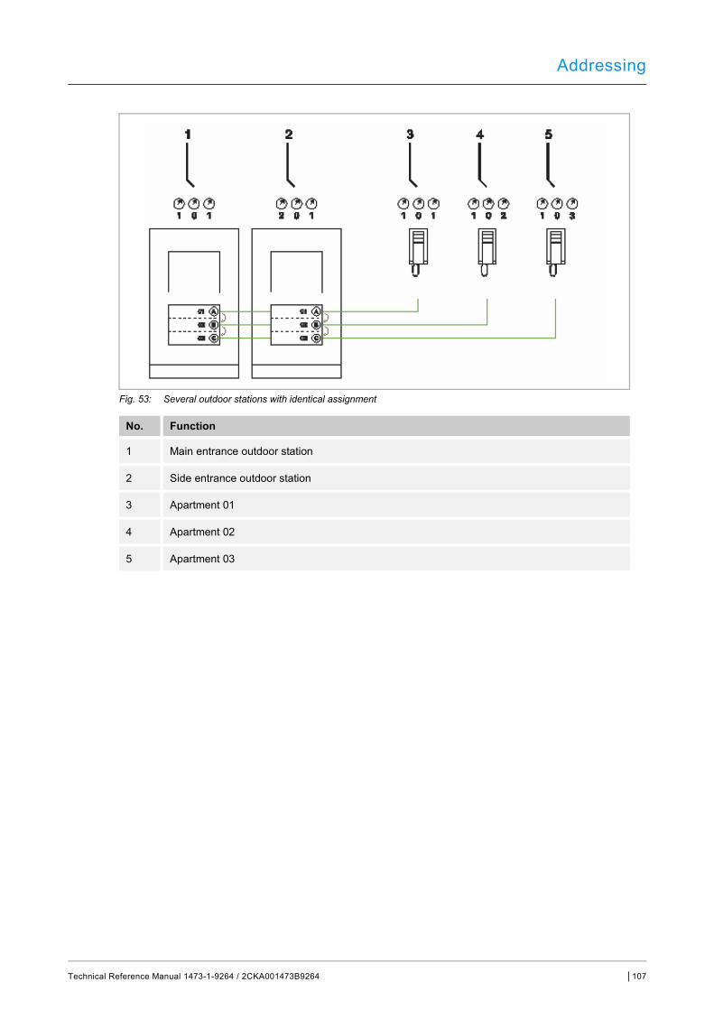
Addressing
Technical Reference Manual 1473-1-9264 / 2CKA001473B9264 │107
Fig. 53: Several outdoor stations with identical assignment
No. Function
1 Main entrance outdoor station
2 Side entrance outdoor station
3 Apartment 01
4 Apartment 02
5 Apartment 03
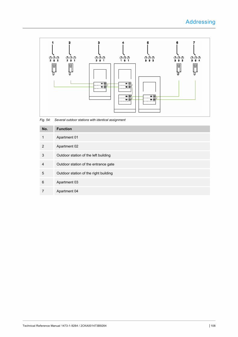
Addressing
Technical Reference Manual 1473-1-9264 / 2CKA001473B9264 │108
Fig. 54: Several outdoor stations with identical assignment
No. Function
1 Apartment 01
2 Apartment 02
3 Outdoor station of the left building
4 Outdoor station of the entrance gate
5 Outdoor station of the right building
6 Apartment 03
7 Apartment 04
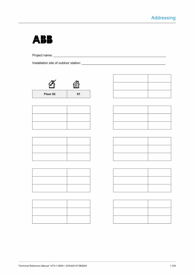
Addressing
Technical Reference Manual 1473-1-9264 / 2CKA001473B9264 │109
Project name: ______________________________________________________________
Installation site of outdoor station: ______________________________________________
Floor 02 01
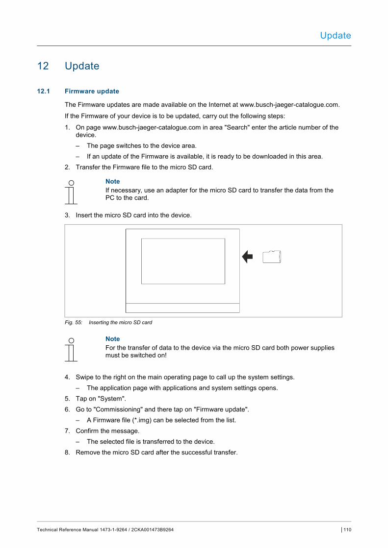
Update
Technical Reference Manual 1473-1-9264 / 2CKA001473B9264 │110
12 Update
12.1 Firmware update
The Firmware updates are made available on the Internet at www.busch-jaeger-catalogue.com.
If the Firmware of your device is to be updated, carry out the following steps:
1. On page www.busch-jaeger-catalogue.com in area "Search" enter the article number of the device. – The page switches to the device area. – If an update of the Firmware is available, it is ready to be downloaded in this area.
2. Transfer the Firmware file to the micro SD card.
Note If necessary, use an adapter for the micro SD card to transfer the data from the PC to the card.
3. Insert the micro SD card into the device.
Fig. 55: Inserting the micro SD card
Note For the transfer of data to the device via the micro SD card both power supplies must be switched on!
4. Swipe to the right on the main operating page to call up the system settings. – The application page with applications and system settings opens.
5. Tap on "System". 6. Go to "Commissioning" and there tap on "Firmware update".
– A Firmware file (*.img) can be selected from the list. 7. Confirm the message.
– The selected file is transferred to the device. 8. Remove the micro SD card after the successful transfer.
Update
Technical Reference Manual 1473-1-9264 / 2CKA001473B9264 │111
12.2 Transfer of PID file
The image file can be transferred to a micro SD card, see chapter 11.6 “Inserting the micro SD card (SDHC)“ on page 98. This micro SD card can be inserted into the panel and the data are transferred to the panel.
1. Transfer the PID file to the micro SD card.
Note If necessary, use an adapter for the micro SD card to transfer the data from the PC to the card.
2. Insert the micro SD card into the device.
Note For the transfer of data to the device via the micro SD card both power supplies must be switched on!
3. Swipe to the right on the main operating page to call up the system settings. – The application page with applications and system settings opens.
4. Tap on "System". 5. Tap on "Commissioning" and there select "Read SD card". 6. Select the appropriate PID file in the list. 7. Confirm the displayed message.
– The data are transferred. 8. Remove the micro SD card after the successful transfer.
Maintenance
Technical Reference Manual 1473-1-9264 / 2CKA001473B9264 │112
13 Maintenance
The device is maintenance-free. In case of damage, e.g. during transport or storage), do not perform repairs. Once the device is opened, the warranty is void.
Access to the device must be guaranteed for operation, testing, inspection, maintenance and repairs (according to DIN VDE 0100-520).
13.1 Cleaning
Caution! Risk of damage to the screen surface The screen surface is sensitive to scratches. Damage to the surface will inhibit the function. ■ Never touch the screen surface with hard objects.
– Use your finger or a plastic stylus. The screen surface can be damaged by cleaning fluids or abrasive agents! ■ Never use abrasive cleaning agents.
– Clean the surfaces using a soft cloth and commercially available glass cleaner.
Note Observe the "Cleaning blockage" function, see chapter 11.7 “System settings“ on page 98.
Control elements and application parameter "Switch" control element
Technical Reference Manual 1473-1-9264 / 2CKA001473B9264 │113
14 Control elements and application parameter
14.1 "Switch" control element
14.1.1 Name of the control element
Options: <Name>
Naming the switch control element, e.g. name of the lamp that is to be switched.
The length of the name is limited to 36 characters.
14.1.2 Function of the control element
Options: Not defined (grey) Light (yellow) Blind (blue) Temperature (orange) Scene (magenta) Alarm (red) Feedback (green)
The parameter is used to specify the colour of the function line.
"Light (yellow)" has been made available for functions of this type.
14.1.3 Size of the button
Options: 1 column
2 columns
The parameter is used to specify whether the control element occupies one column (one button or control frame) or two columns (two buttons or control frames).
14.1.4 Type of switch
Options: Switchover
Press/release
Short/long
Note The selection depends on the type of switch.
The parameter is used to specify the signals (values) the switch sends to the KNX bus when it is operated.
– Switchover: No additional parameters available. – Pressing/releasing: Pressing = value 1; releasing = value 2.
The following supplementary parameters are available, see chapter 15.1.5 “Object type 1 / value 2“ on page 114:
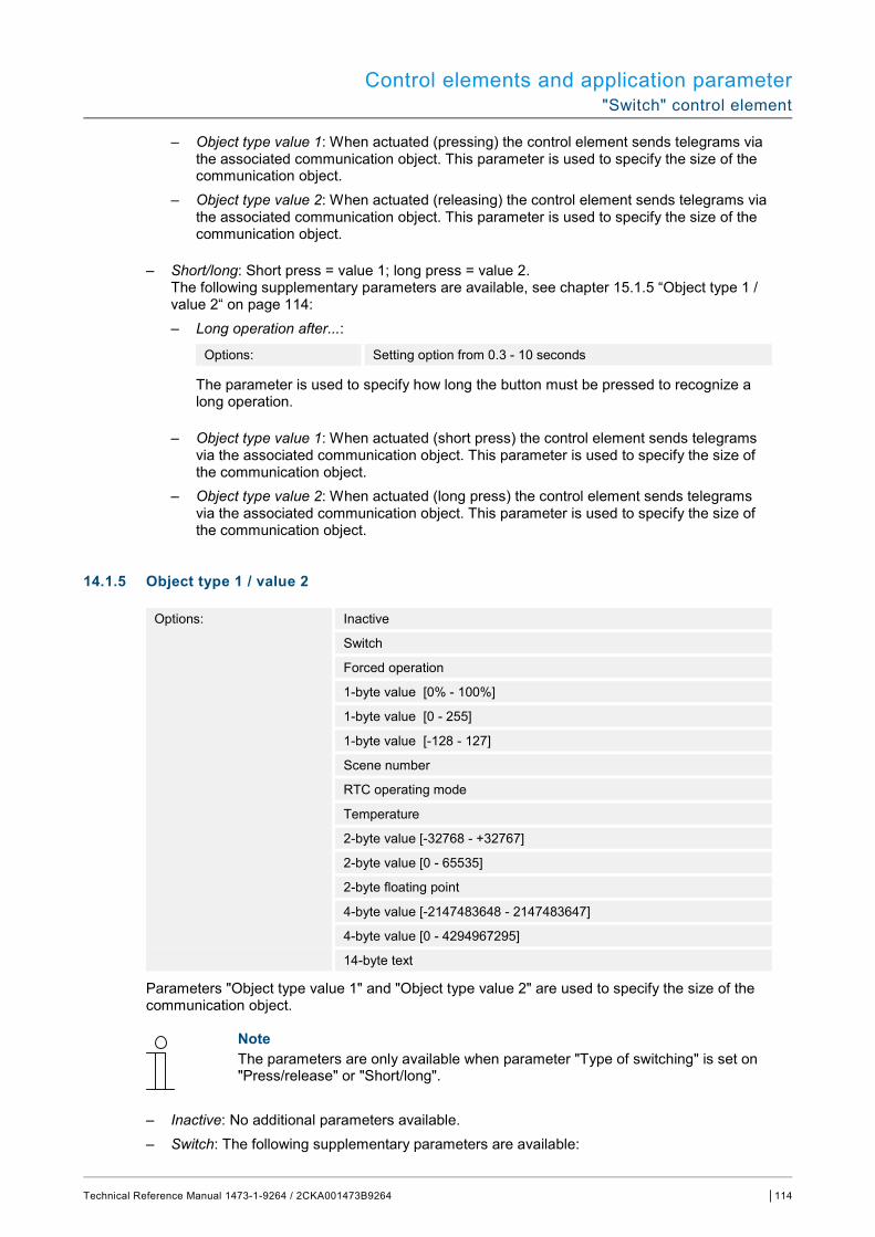
Control elements and application parameter "Switch" control element
Technical Reference Manual 1473-1-9264 / 2CKA001473B9264 │114
– Object type value 1: When actuated (pressing) the control element sends telegrams via the associated communication object. This parameter is used to specify the size of the communication object.
– Object type value 2: When actuated (releasing) the control element sends telegrams via the associated communication object. This parameter is used to specify the size of the communication object.
– Short/long: Short press = value 1; long press = value 2. The following supplementary parameters are available, see chapter 15.1.5 “Object type 1 / value 2“ on page 114: – Long operation after...:
Options: Setting option from 0.3 - 10 seconds
The parameter is used to specify how long the button must be pressed to recognize a long operation.
– Object type value 1: When actuated (short press) the control element sends telegrams via the associated communication object. This parameter is used to specify the size of the communication object.
– Object type value 2: When actuated (long press) the control element sends telegrams via the associated communication object. This parameter is used to specify the size of the communication object.
14.1.5 Object type 1 / value 2
Options: Inactive
Switch
Forced operation
1-byte value [0% - 100%]
1-byte value [0 - 255]
1-byte value [-128 - 127]
Scene number
RTC operating mode
Temperature
2-byte value [-32768 - +32767]
2-byte value [0 - 65535]
2-byte floating point
4-byte value [-2147483648 - 2147483647]
4-byte value [0 - 4294967295]
14-byte text
Parameters "Object type value 1" and "Object type value 2" are used to specify the size of the communication object.
Note The parameters are only available when parameter "Type of switching" is set on "Press/release" or "Short/long".
– Inactive: No additional parameters available. – Switch: The following supplementary parameters are available:

Control elements and application parameter "Switch" control element
Technical Reference Manual 1473-1-9264 / 2CKA001473B9264 │115
Sent value 1:
Options: Switchover
0
1
– Switchover: At each actuation a switchover takes place between the two set values "Object type 1" and "Object type 2".
– 0 / 1: Switching commands are sent with 1 bit (0 or 1), e.g. for switching a switching actuator.
Sent value 2:
Options: 0
1
– 0 / 1: Switching commands are sent with 1 bit (0 or 1), e.g. for switching a switching actuator.
– Forced operation: Management systems can access the device directly via KNX. However, it can also be specified that one can select manually (forced operation) via buttons. The following supplementary parameter is available: Sent value 1 / value 2:
Options: ON, forced operation active
OFF, forced operation active
Deactivate forced operation
– 1-byte value [0% - 100%]: A value is sent as 1-byte value without a sign (percentage value). The following supplementary parameter is available: Sent value 1 / value 2 [0 - 100%]:
Options: Setting option from 0 - 100
– 1-byte value [0 - 255]: A value is sent as 1-byte value without a sign, e.g. actuating value, angle or brightness value. The following supplementary parameter is available: Sent value 1 / value 2 [0 - 255]:
Options: Setting option from 0 - 255
– 1-byte value [-128 - 127]: A value is sent as 1-byte value with a sign, e.g. actuating value. The following supplementary parameter is available: Sent value 1 / value 2 [-128 - 127]:
Options: Setting option from -128 - +127
– Scene number: The parameter is used to select a 1-byte object to link it with a scene number. Values between 1 and 64 are available for light scene numbers. The following supplementary parameter is available:
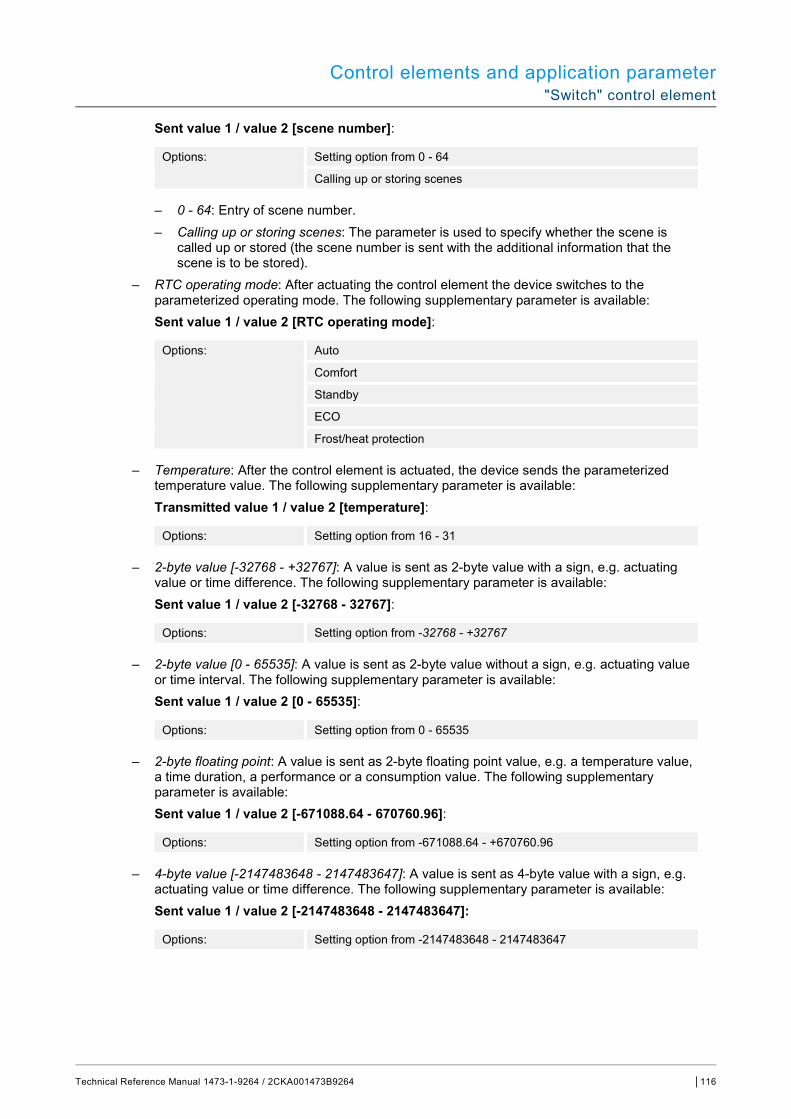
Control elements and application parameter "Switch" control element
Technical Reference Manual 1473-1-9264 / 2CKA001473B9264 │116
Sent value 1 / value 2 [scene number]:
Options: Setting option from 0 - 64
Calling up or storing scenes
– 0 - 64: Entry of scene number. – Calling up or storing scenes: The parameter is used to specify whether the scene is
called up or stored (the scene number is sent with the additional information that the scene is to be stored).
– RTC operating mode: After actuating the control element the device switches to the parameterized operating mode. The following supplementary parameter is available: Sent value 1 / value 2 [RTC operating mode]:
Options: Auto
Comfort
Standby
ECO
Frost/heat protection
– Temperature: After the control element is actuated, the device sends the parameterized temperature value. The following supplementary parameter is available: Transmitted value 1 / value 2 [temperature]:
Options: Setting option from 16 - 31
– 2-byte value [-32768 - +32767]: A value is sent as 2-byte value with a sign, e.g. actuating value or time difference. The following supplementary parameter is available: Sent value 1 / value 2 [-32768 - 32767]:
Options: Setting option from -32768 - +32767
– 2-byte value [0 - 65535]: A value is sent as 2-byte value without a sign, e.g. actuating value or time interval. The following supplementary parameter is available: Sent value 1 / value 2 [0 - 65535]:
Options: Setting option from 0 - 65535
– 2-byte floating point: A value is sent as 2-byte floating point value, e.g. a temperature value, a time duration, a performance or a consumption value. The following supplementary parameter is available: Sent value 1 / value 2 [-671088.64 - 670760.96]:
Options: Setting option from -671088.64 - +670760.96
– 4-byte value [-2147483648 - 2147483647]: A value is sent as 4-byte value with a sign, e.g. actuating value or time difference. The following supplementary parameter is available: Sent value 1 / value 2 [-2147483648 - 2147483647]:
Options: Setting option from -2147483648 - 2147483647
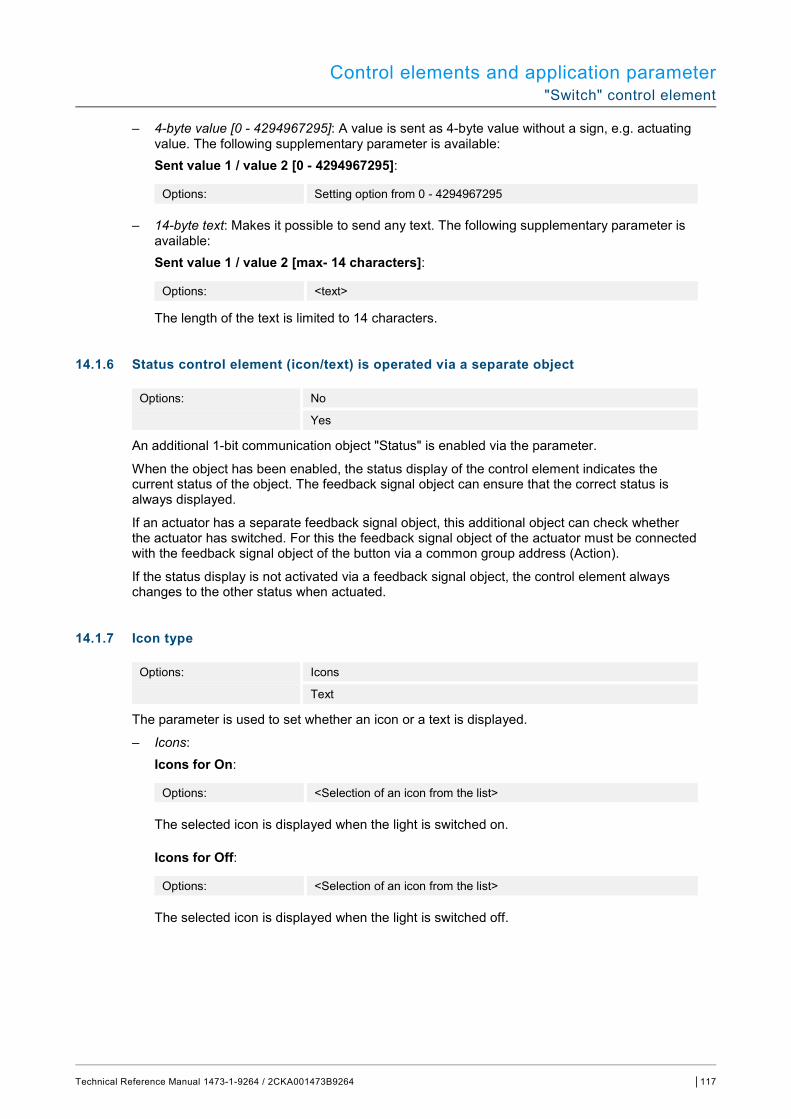
Control elements and application parameter "Switch" control element
Technical Reference Manual 1473-1-9264 / 2CKA001473B9264 │117
– 4-byte value [0 - 4294967295]: A value is sent as 4-byte value without a sign, e.g. actuating value. The following supplementary parameter is available: Sent value 1 / value 2 [0 - 4294967295]:
Options: Setting option from 0 - 4294967295
– 14-byte text: Makes it possible to send any text. The following supplementary parameter is available: Sent value 1 / value 2 [max- 14 characters]:
Options: <text>
The length of the text is limited to 14 characters.
14.1.6 Status control element (icon/text) is operated via a separate object
Options: No
Yes
An additional 1-bit communication object "Status" is enabled via the parameter.
When the object has been enabled, the status display of the control element indicates the current status of the object. The feedback signal object can ensure that the correct status is always displayed.
If an actuator has a separate feedback signal object, this additional object can check whether the actuator has switched. For this the feedback signal object of the actuator must be connected with the feedback signal object of the button via a common group address (Action).
If the status display is not activated via a feedback signal object, the control element always changes to the other status when actuated.
14.1.7 Icon type
Options: Icons
Text
The parameter is used to set whether an icon or a text is displayed.
– Icons: Icons for On:
Options: <Selection of an icon from the list>
The selected icon is displayed when the light is switched on.
Icons for Off:
Options: <Selection of an icon from the list>
The selected icon is displayed when the light is switched off.
Control elements and application parameter "Switch" control element
Technical Reference Manual 1473-1-9264 / 2CKA001473B9264 │118
– Text: Text for On:
Options: <text>
The entered text is displayed when the light is switched on.
Text for Off:
Options: <text>
The entered text is displayed when the light is switched off.
14.1.8 Enable 1-bit communication object "Disable"
Options: No
Yes
There is the option of temporarily disabling the function via an additional communication object "Disable".
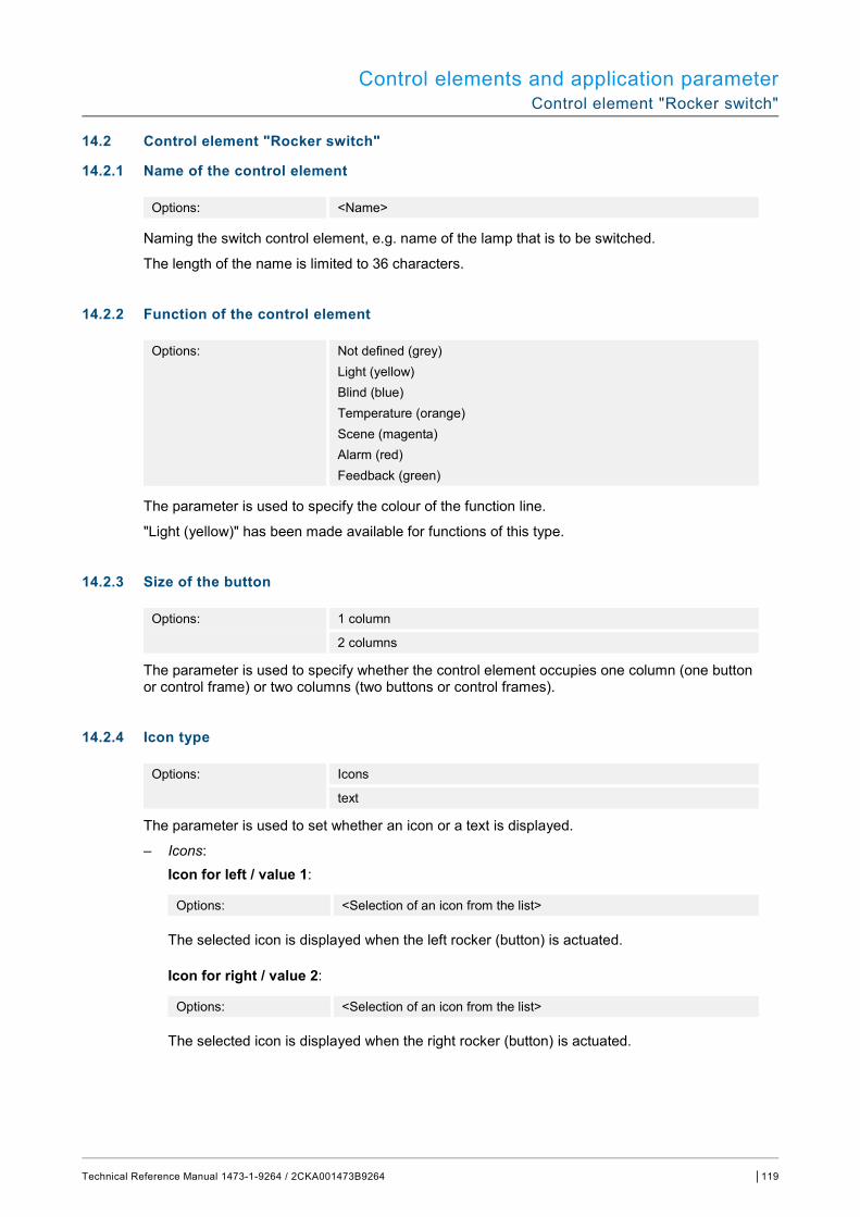
Control elements and application parameter Control element "Rocker switch"
Technical Reference Manual 1473-1-9264 / 2CKA001473B9264 │119
14.2 Control element "Rocker switch"
14.2.1 Name of the control element
Options: <Name>
Naming the switch control element, e.g. name of the lamp that is to be switched.
The length of the name is limited to 36 characters.
14.2.2 Function of the control element
Options: Not defined (grey) Light (yellow) Blind (blue) Temperature (orange) Scene (magenta) Alarm (red) Feedback (green)
The parameter is used to specify the colour of the function line.
"Light (yellow)" has been made available for functions of this type.
14.2.3 Size of the button
Options: 1 column
2 columns
The parameter is used to specify whether the control element occupies one column (one button or control frame) or two columns (two buttons or control frames).
14.2.4 Icon type
Options: Icons
text
The parameter is used to set whether an icon or a text is displayed.
– Icons: Icon for left / value 1:
Options: <Selection of an icon from the list>
The selected icon is displayed when the left rocker (button) is actuated.
Icon for right / value 2:
Options: <Selection of an icon from the list>
The selected icon is displayed when the right rocker (button) is actuated.
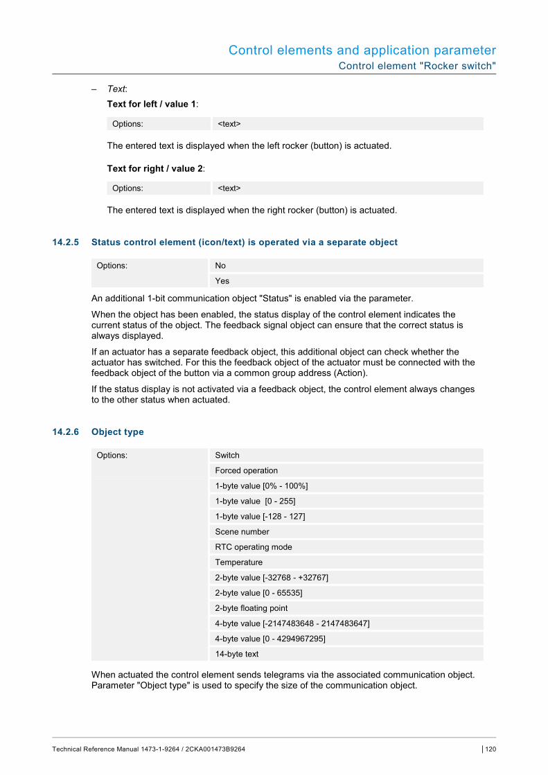
Control elements and application parameter Control element "Rocker switch"
Technical Reference Manual 1473-1-9264 / 2CKA001473B9264 │120
– Text: Text for left / value 1:
Options: <text>
The entered text is displayed when the left rocker (button) is actuated.
Text for right / value 2:
Options: <text>
The entered text is displayed when the right rocker (button) is actuated.
14.2.5 Status control element (icon/text) is operated via a separate object
Options: No
Yes
An additional 1-bit communication object "Status" is enabled via the parameter.
When the object has been enabled, the status display of the control element indicates the current status of the object. The feedback signal object can ensure that the correct status is always displayed.
If an actuator has a separate feedback object, this additional object can check whether the actuator has switched. For this the feedback object of the actuator must be connected with the feedback object of the button via a common group address (Action).
If the status display is not activated via a feedback object, the control element always changes to the other status when actuated.
14.2.6 Object type
Options: Switch
Forced operation
1-byte value [0% - 100%]
1-byte value [0 - 255]
1-byte value [-128 - 127]
Scene number
RTC operating mode
Temperature
2-byte value [-32768 - +32767]
2-byte value [0 - 65535]
2-byte floating point
4-byte value [-2147483648 - 2147483647]
4-byte value [0 - 4294967295]
14-byte text
When actuated the control element sends telegrams via the associated communication object. Parameter "Object type" is used to specify the size of the communication object.

Control elements and application parameter Control element "Rocker switch"
Technical Reference Manual 1473-1-9264 / 2CKA001473B9264 │121
Note Value 1 is assigned to the left button, and value 2 to the right button.
– Switch: The following supplementary parameter is available: Sent value 1 / value 2:
Options: 0
1
– 0 / 1: Switching commands are sent with 1 bit (0 or 1), e.g. for switching a switching actuator.
– Forced operation: Management systems can access the device directly via KNX. It can additionally be specified that selection can be carried out manually via buttons (forced operation). The following supplementary parameter is available: Sent value 1 / value 2:
Options: ON, forced operation active
OFF, forced operation active
Deactivate forced operation
– 1-byte value [0% - 100%]: A value is sent as 1-byte percentage value. The following supplementary parameter is available: Sent value 1 / value 2 [0 - 100%]:
Options: Setting option from 0 - 100
– 1-byte value [0 - 255]: A value is sent as 1-byte value without a sign, e.g. actuating value, angle or brightness value. The following supplementary parameter is available: Sent value 1 / value 2 [0 - 255]:
Options: Setting option from 0 - 255
– 1-byte value [-128 - 127]: A value is sent as 1-byte value with a sign, e.g. actuating value. The following supplementary parameter is available: Sent value 1 / value 2 [-128 - 127]:
Options: Setting option from -128 - +127
– Scene number: The parameter is used to select a 1-byte object to link it with a scene number. Values between 1 and 64 are available for light scene numbers. The following supplementary parameter is available: Transmitted value 1 / value 2 [scene number]:
Options: Setting option from 0 - 64
Calling up or storing scenes
– 0 - 64: Entry of scene number. – Calling up or storing scenes: The parameter is used to specify whether the scene is
called up or stored (the scene number is sent with the additional information that the scene is to be stored).
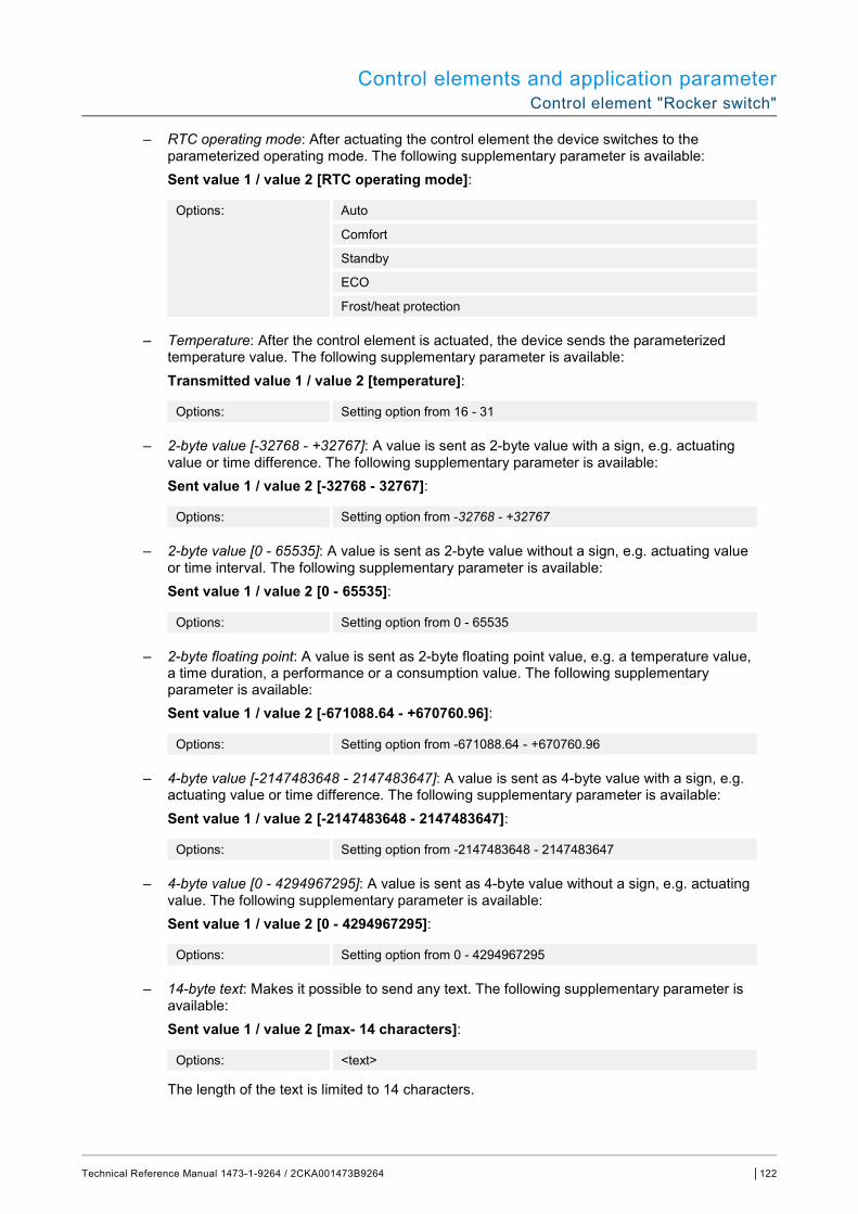
Control elements and application parameter Control element "Rocker switch"
Technical Reference Manual 1473-1-9264 / 2CKA001473B9264 │122
– RTC operating mode: After actuating the control element the device switches to the parameterized operating mode. The following supplementary parameter is available: Sent value 1 / value 2 [RTC operating mode]:
Options: Auto
Comfort
Standby
ECO
Frost/heat protection
– Temperature: After the control element is actuated, the device sends the parameterized temperature value. The following supplementary parameter is available: Transmitted value 1 / value 2 [temperature]:
Options: Setting option from 16 - 31
– 2-byte value [-32768 - +32767]: A value is sent as 2-byte value with a sign, e.g. actuating value or time difference. The following supplementary parameter is available: Sent value 1 / value 2 [-32768 - 32767]:
Options: Setting option from -32768 - +32767
– 2-byte value [0 - 65535]: A value is sent as 2-byte value without a sign, e.g. actuating value or time interval. The following supplementary parameter is available: Sent value 1 / value 2 [0 - 65535]:
Options: Setting option from 0 - 65535
– 2-byte floating point: A value is sent as 2-byte floating point value, e.g. a temperature value, a time duration, a performance or a consumption value. The following supplementary parameter is available: Sent value 1 / value 2 [-671088.64 - +670760.96]:
Options: Setting option from -671088.64 - +670760.96
– 4-byte value [-2147483648 - 2147483647]: A value is sent as 4-byte value with a sign, e.g. actuating value or time difference. The following supplementary parameter is available: Sent value 1 / value 2 [-2147483648 - 2147483647]:
Options: Setting option from -2147483648 - 2147483647
– 4-byte value [0 - 4294967295]: A value is sent as 4-byte value without a sign, e.g. actuating value. The following supplementary parameter is available: Sent value 1 / value 2 [0 - 4294967295]:
Options: Setting option from 0 - 4294967295
– 14-byte text: Makes it possible to send any text. The following supplementary parameter is available: Sent value 1 / value 2 [max- 14 characters]:
Options: <text>
The length of the text is limited to 14 characters.

Control elements and application parameter Control element "Rocker switch"
Technical Reference Manual 1473-1-9264 / 2CKA001473B9264 │123
14.2.7 Enable 1-bit communication object "Disable"
Options: No
Yes
There is the option of temporarily disabling the function via an additional communication object "Disable".
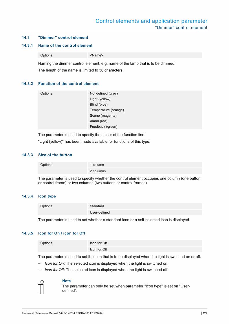
Control elements and application parameter "Dimmer" control element
Technical Reference Manual 1473-1-9264 / 2CKA001473B9264 │124
14.3 "Dimmer" control element
14.3.1 Name of the control element
Options: <Name>
Naming the dimmer control element, e.g. name of the lamp that is to be dimmed.
The length of the name is limited to 36 characters.
14.3.2 Function of the control element
Options: Not defined (grey) Light (yellow) Blind (blue) Temperature (orange) Scene (magenta) Alarm (red) Feedback (green)
The parameter is used to specify the colour of the function line.
"Light (yellow)" has been made available for functions of this type.
14.3.3 Size of the button
Options: 1 column
2 columns
The parameter is used to specify whether the control element occupies one column (one button or control frame) or two columns (two buttons or control frames).
14.3.4 Icon type
Options: Standard
User-defined
The parameter is used to set whether a standard icon or a self-selected icon is displayed.
14.3.5 Icon for On / icon for Off
Options: Icon for On
Icon for Off
The parameter is used to set the icon that is to be displayed when the light is switched on or off.
– Icon for On: The selected icon is displayed when the light is switched on. – Icon for Off: The selected icon is displayed when the light is switched off.
Note The parameter can only be set when parameter "Icon type" is set on "User-defined".

Control elements and application parameter "Dimmer" control element
Technical Reference Manual 1473-1-9264 / 2CKA001473B9264 │125
14.3.6 Position for dim up icon
Options: Left
Right
The parameter is used to set whether the icon for "Dim up" is positioned on the right or left side.
14.3.7 Icon for dim up / icon for dim down
Options: Icon for dim up
Icon for dim down
The parameter is used to set the icon that is to be displayed when the light is dimmed up or down.
– Icon for dim up: The selected icon is displayed when the light is dimmed up. – Icon for dim down: The selected icon is displayed when the light is dimmed down.
14.3.8 Status control element (icon) is operated via a separate object
Options: No
Yes
An additional 1-bit communication object "Status" is enabled via the parameter.
When the object has been enabled, the status display of the control element indicates the current status of the object. The feedback object can ensure that the correct status is always displayed.
If an actuator has a separate feedback object, this additional object can check whether the actuator has switched. For this the feedback object of the actuator must be connected with the feedback object of the button via a common group address (Action).
If the status display is not activated via a feedback object, the control element always changes to the other status when actuated.
14.3.9 Status of dimming value is controlled by a separate object
Options: No
Yes
– No: No additional parameters available. – Yes: The brightness value signalled by the dimmer can be displayed via a separate object.
An additional 1-bit communication object "Status value" is enabled. The displayed value does not originate from the control element. The value is received via a separate feedback object. The following parameter appears:
Display value in control element:
Options: No
Yes
– No: No additional parameters available. – Yes: The following parameter appears:
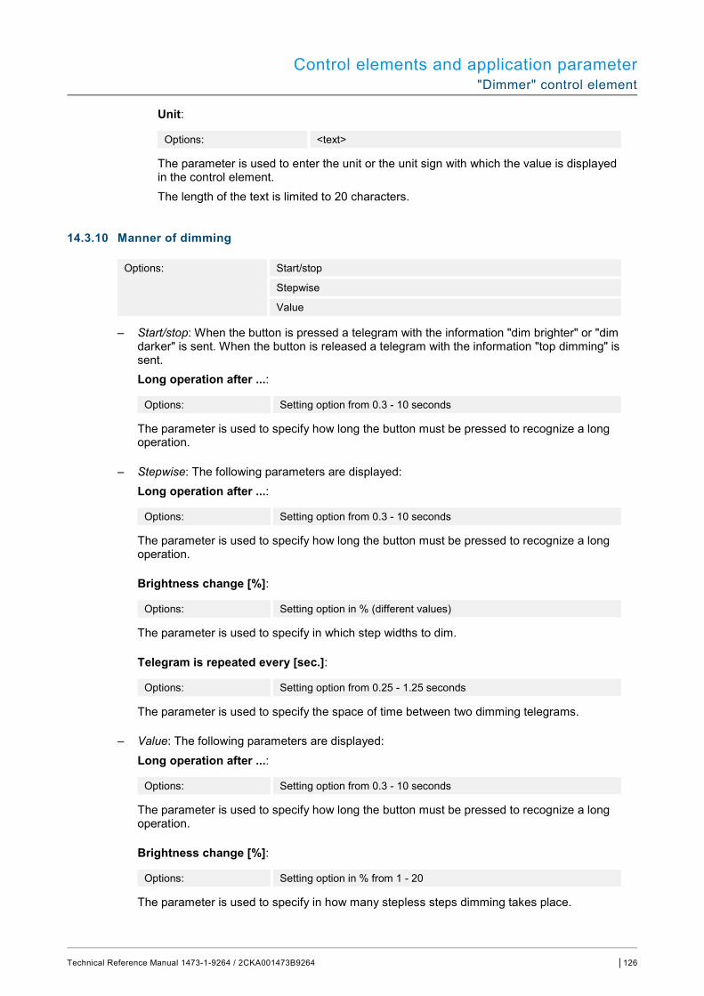
Control elements and application parameter "Dimmer" control element
Technical Reference Manual 1473-1-9264 / 2CKA001473B9264 │126
Unit:
Options: <text>
The parameter is used to enter the unit or the unit sign with which the value is displayed in the control element.
The length of the text is limited to 20 characters.
14.3.10 Manner of dimming
Options: Start/stop
Stepwise
Value
– Start/stop: When the button is pressed a telegram with the information "dim brighter" or "dim darker" is sent. When the button is released a telegram with the information "top dimming" is sent. Long operation after ...:
Options: Setting option from 0.3 - 10 seconds
The parameter is used to specify how long the button must be pressed to recognize a long operation.
– Stepwise: The following parameters are displayed: Long operation after ...:
Options: Setting option from 0.3 - 10 seconds
The parameter is used to specify how long the button must be pressed to recognize a long operation.
Brightness change [%]:
Options: Setting option in % (different values)
The parameter is used to specify in which step widths to dim.
Telegram is repeated every [sec.]:
Options: Setting option from 0.25 - 1.25 seconds
The parameter is used to specify the space of time between two dimming telegrams.
– Value: The following parameters are displayed: Long operation after ...:
Options: Setting option from 0.3 - 10 seconds
The parameter is used to specify how long the button must be pressed to recognize a long operation.
Brightness change [%]:
Options: Setting option in % from 1 - 20
The parameter is used to specify in how many stepless steps dimming takes place.
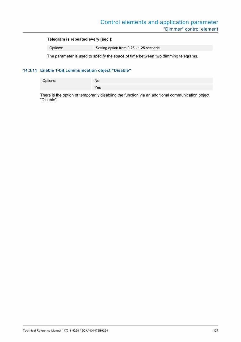
Control elements and application parameter "Dimmer" control element
Technical Reference Manual 1473-1-9264 / 2CKA001473B9264 │127
Telegram is repeated every [sec.]:
Options: Setting option from 0.25 - 1.25 seconds
The parameter is used to specify the space of time between two dimming telegrams.
14.3.11 Enable 1-bit communication object "Disable"
Options: No
Yes
There is the option of temporarily disabling the function via an additional communication object "Disable".

Control elements and application parameter Control element: "Dimmer slider"
Technical Reference Manual 1473-1-9264 / 2CKA001473B9264 │128
14.4 Control element: "Dimmer slider"
14.4.1 Name of the control element
Options: <Name>
Naming the slider control element, e.g. name of the lamp that is to be dimmed.
The length of the name is limited to 36 characters.
14.4.2 Function of the control element
Options: Not defined (grey) Light (yellow) Blind (blue) Temperature (orange) Scene (magenta) Alarm (red) Feedback (green)
The parameter is used to specify the colour of the function line.
"Light (yellow)" has been made available for functions of this type.
14.4.3 Size of the button
Options: 2 columns
3 columns
The parameter is used to specify whether the control element occupies two columns (two buttons or control frames) or three columns (three buttons or control frames).
14.4.4 Icon type
Options: Standard
User-defined
The parameter is used to set whether a standard icon or a self-selected icon is displayed.
14.4.5 Icon for On / icon for Off
Options: Icon for On
Icon for Off
The parameter is used to set the icon that is to be displayed when the light is switched on or off.
– Icon for On: The selected icon is displayed when the light is switched on. – Icon for Off: The selected icon is displayed when the light is switched off.
Note The parameter can only be set when parameter "Icon type" is set on "User-defined".
Control elements and application parameter Control element: "Dimmer slider"
Technical Reference Manual 1473-1-9264 / 2CKA001473B9264 │129
14.4.6 Slider from
Options: Left to right
Right to left
The parameter is used to specify whether the slider is to shift from left to right or from right to left.
14.4.7 Status control element (icon) is operated via a separate object
Options: No
Yes
An additional 1-bit communication object "Switch status" is enabled via the parameter.
When the object has been enabled, the status display of the control element indicates the current status of the object. The feedback object can ensure that the correct status is always displayed.
If an actuator has a separate feedback object, this additional object can check whether the actuator has switched. For this the feedback object of the actuator must be connected with the feedback object of the button via a common group address (Action).
If the status display is not activated via a feedback object, the control element always changes to the other status when actuated.
14.4.8 Display value in control element
Options: No
Yes
The parameter is used to specify whether the dimming value is displayed in the control element.
– No: No display. No additional parameters available. – Yes: The following parameters are displayed: Status of dimming value is controlled by a separate object:
Options: No
Yes
The brightness value signalled by the dimmer slider can be displayed via a separate object. An additional 1-bit communication object "Status value" is enabled. The displayed value does not originate from the control element. The value is received via a separate feedback object. Unit:
Options: <text>
The parameter is used to enter the unit or the unit sign with which the value is displayed in the control element. The length of the text is limited to 20 characters.

Control elements and application parameter Control element: "Dimmer slider"
Technical Reference Manual 1473-1-9264 / 2CKA001473B9264 │130
14.4.9 Slider sends
Options: When releasing the slider
Cyclic
The parameter is used to specify whether the signal is sent "When releasing the slider" or "Cyclic".
– When releasing the slider: No additional parameters available. – Cyclic: The following supplementary parameter is available: Telegram is repeated every [sec.]:
Options: Setting option from 0.25 - 1.25 seconds
The parameter is used to specify the space of time between two dimming telegrams.
14.4.10 Brightness change [%]
Options: Setting option from 1 - 20
The parameter is used to set the number of steps (in percent) for dimming. The brightness change takes place when the slider is released.
14.4.11 Enable 1-bit communication object "Disable"
Options: No
Yes
There is the option of temporarily disabling the function via an additional communication object "Disable".
Control elements and application parameter Operation of "RGBW" control element“
Technical Reference Manual 1473-1-9264 / 2CKA001473B9264 │131
14.5 Operation of "RGBW" control element“
14.5.1 Name of the control element
Options: <Name>
Naming the switch control element, e.g. name of the lamp that is to be switched.
The length of the name is limited to 36 characters.
14.5.2 Function of the control element
Options: Not defined (grey) Light (yellow) Blind (blue) Temperature (orange) Scene (magenta) Alarm (red) Feedback (green)
The parameter is used to specify the colour of the function line.
"Light (yellow)" has been made available for functions of this type.
14.5.3 Display value in control element
Options: No
Yes
The parameter is used to specify whether the RGBW value is displayed in the control element.
14.5.4 Type of colour/white lamp
Options: RGB
RGB+W
RGB+WW/CW
WW/CW
The parameter is used to specify how the colour activation is to be controlled. Corresponding sliders will be displayed in the control element. The type of colour control depends on the type of lamp. Specific settings can be made for the lamps. For example, the colours can be changed or the warm-white component can be adjusted.
– RGB: Used for RGB lamp. The following supplementary parameter is available: Switching On/Off via:
Options: Switch object
RGB feedback signal
The parameter is used to specify the On/Off control. – Switch object: Setting, when the lamp contains a "Switch" object. The following
supplementary parameters are available:
Control elements and application parameter Operation of "RGBW" control element“
Technical Reference Manual 1473-1-9264 / 2CKA001473B9264 │132
Switched On -> preset value:
Options: No
Yes
– No: No presets are sent when the lamp is switched on. – Yes: The stored presets are sent when the lamp is switched on.
Switched Off -> RGB value 0,0,0:
Options: No
Yes
– No: No RGB values are sent when the lamp is switched off. – Yes: The RGB values (0,0,0) are sent when the lamp is switched off. This parameter
is important for lamps that do not contain a "Switch" object. – RGB feedback: Setting when the lamp contains no "Switch" object but is switched off via
the RGB values.
– RGB+W: Used for RGB lamp with integrated white component. The following supplementary parameters are available:
Switching On/Off via:
Options: 1 object
2 objects
The parameter is used to specify the On/Off control. – 1 Object: Setting when the lamp has only one channel (e.g. Philips Hue). – 2 Objects: Setting when the lamp has several channels (RGB and White separated, e.g.
two stripes), separate ON/OFF switching via data points. Switched On -> preset value:
Options: No
Yes
– No: No presets are sent when the lamp is switched on. – Yes: The stored presets are sent when the lamp is switched on.
Switched Off -> RGB value 0,0,0:
Options: No
Yes
– No: No RGB values are sent when the lamp is switched off. – Yes: The RGB values (0,0,0) are sent when the lamp is switched off. This parameter is
important for lamps that do not contain a "Switch" object.
– RGB+WW/CW: Used for RGB lamp with integrated Warm White and Cold White component. The following supplementary parameters are available:

Control elements and application parameter Operation of "RGBW" control element“
Technical Reference Manual 1473-1-9264 / 2CKA001473B9264 │133
White activation via:
Options: Warm/Cold objects
Temperature/brightness (Hue) objects
The parameter is used to specify how the white lamps are controlled. – Warm/cold objects: The activation takes place via separate channels, i.e. via a "Warm
White" (WW) and a "Cold White" (CW) channel. Prerequisite: The lamp to be controlled has different channels (e.g. 2 stripes).
– Temperature/brightness objects (Hue): If no separate channels are available (e.g. Philips Hue), activation takes place via the colour temperature and brightness. The communication objects are named the same for both types of activation; however, different values are sent (either colour temperature or Cold White and Warm White).
Switching On/Off via:
Options: 1 object
2 objects
The parameter is used to specify the On/Off control. – 1 Object: Setting when the lamp has only one channel (e.g. Philips Hue). – 2 Objects: Setting when the lamp has several channels (RGB and White separated, e.g.
two stripes), separate ON/OFF switching via data points. Switched On -> preset value:
Options: No
Yes
– No: No presets are sent when the lamp is switched on. – Yes: The stored presets are sent when the lamp is switched on.
Switched Off -> RGB value 0,0,0:
Options: No
Yes
– No: No RGB values are sent when the lamp is switched off. – Yes: The RGB values (0,0,0) are sent when the lamp is switched off. This parameter is
important for lamps that do not have a "Switch" object.
– WW/CW: Used for lamps with Warm White and Cold White component. The following supplementary parameters are available:
White activation via:
Options: Warm/Cold objects
Temperature/brightness (Hue) objects
The parameter is used to specify how the white lamps are controlled. – Warm/cold objects: The activation takes place via separate channels, i.e. via a "Warm
White" (WW) and a "Cold White" (CW) channel. Prerequisite: The lamp to be controlled has different channels (e.g. 2 stripes).
– Temperature/brightness objects (Hue): If no separate channels are available (e.g. Philips Hue), activation takes place via the colour temperature and brightness. The communication objects are named the same for both types of activation; however, different values are sent (either colour temperature or Cold White and Warm White).
Control elements and application parameter Operation of "RGBW" control element“
Technical Reference Manual 1473-1-9264 / 2CKA001473B9264 │134
14.5.5 Brightness change [%]
Options: Setting option from 1 - 20
The parameter is used to set the number of steps (in percent) for dimming. The brightness change takes place when the slider is released.
14.5.6 Telegram is repeated every [sec.]:
Options: Setting option from 0.25 - 1.25 seconds
The parameter is used to specify the space of time between two telegrams.
14.5.7 Enable 1-bit communication object "Disable"
Options: No
Yes
There is the option of temporarily disabling the function via an additional communication object "Disable".
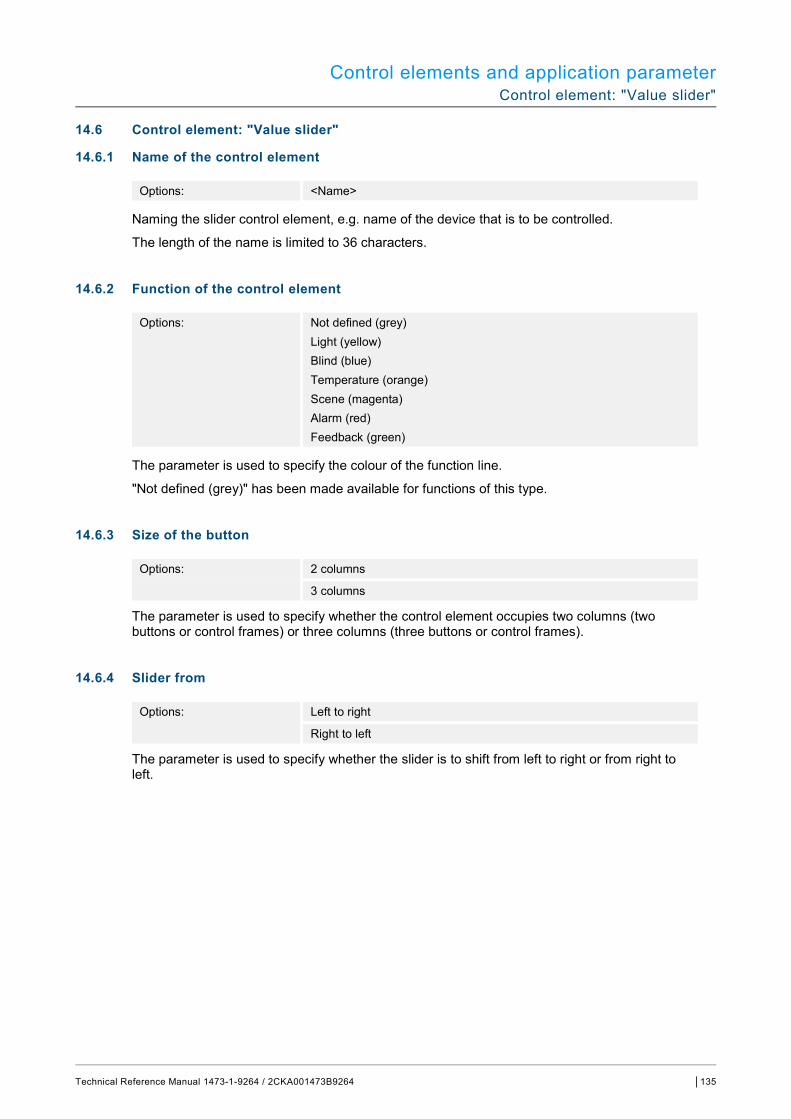
Control elements and application parameter Control element: "Value slider"
Technical Reference Manual 1473-1-9264 / 2CKA001473B9264 │135
14.6 Control element: "Value slider"
14.6.1 Name of the control element
Options: <Name>
Naming the slider control element, e.g. name of the device that is to be controlled.
The length of the name is limited to 36 characters.
14.6.2 Function of the control element
Options: Not defined (grey) Light (yellow) Blind (blue) Temperature (orange) Scene (magenta) Alarm (red) Feedback (green)
The parameter is used to specify the colour of the function line.
"Not defined (grey)" has been made available for functions of this type.
14.6.3 Size of the button
Options: 2 columns
3 columns
The parameter is used to specify whether the control element occupies two columns (two buttons or control frames) or three columns (three buttons or control frames).
14.6.4 Slider from
Options: Left to right
Right to left
The parameter is used to specify whether the slider is to shift from left to right or from right to left.

Control elements and application parameter Control element: "Value slider"
Technical Reference Manual 1473-1-9264 / 2CKA001473B9264 │136
14.6.5 Display value in control element
Options: No
Yes
The parameter is used to specify whether the value is displayed in the control element.
– No: No display. No additional parameters available. – Yes: The following supplementary parameters are displayed: Status value is controlled by a separate object:
Options: No
Yes
An additional 1-bit communication object "Status value" is enabled via the parameter. If an actuator has a separate object to feed back the status, it can be linked with a separate feedback object. Unit:
Options: <text>
The parameter is used to enter the unit or the unit sign with which the value is displayed in the control element. The length is limited to 20 characters. Decimal places:
Options: Setting option from 0 - 2
The parameter is used to specify the number of decimal places of the displayed value. The number is limited to 2 places.
14.6.6 Slider sends
Options: When releasing the slider
Cyclic
The parameter is used to specify whether the signal is sent "When releasing the slider" or "Cyclic".
– When releasing the slider: No additional parameters available. – Cyclic: The following supplementary parameter is available: Telegram is repeated every [sec.]:
Options: Setting option from 0.25 - 1.25 seconds
The parameter is used to specify the space of time between two value telegrams.
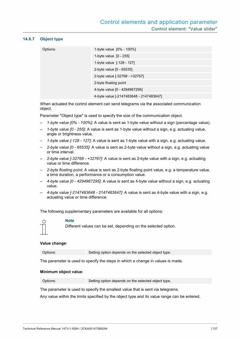
Control elements and application parameter Control element: "Value slider"
Technical Reference Manual 1473-1-9264 / 2CKA001473B9264 │137
14.6.7 Object type
Options: 1-byte value [0% - 100%]
1-byte value [0 - 255]
1-byte value [-128 - 127]
2-byte value [0 - 65535]
2-byte value [-32768 - +32767]
2-byte floating point
4-byte value [0 - 4294967295]
4-byte value [-2147483648 - 2147483647]
When actuated the control element can send telegrams via the associated communication object.
Parameter "Object type" is used to specify the size of the communication object.
– 1-byte value [0% - 100%]: A value is sent as 1-byte value without a sign (percentage value). – 1-byte value [0 - 255]: A value is sent as 1-byte value without a sign, e.g. actuating value,
angle or brightness value. – 1-byte value [-128 - 127]: A value is sent as 1-byte value with a sign, e.g. actuating value. – 2-byte value [0 - 65535]: A value is sent as 2-byte value without a sign, e.g. actuating value
or time interval. – 2-byte value [-32768 - +32767]: A value is sent as 2-byte value with a sign, e.g. actuating
value or time difference. – 2-byte floating point: A value is sent as 2-byte floating point value, e.g. a temperature value,
a time duration, a performance or a consumption value. – 4-byte value [0 - 4294967295]: A value is sent as 4-byte value without a sign, e.g. actuating
value. – 4-byte value [-2147483648 - 2147483647]: A value is sent as 4-byte value with a sign, e.g.
actuating value or time difference.
The following supplementary parameters are available for all options:
Note Different values can be set, depending on the selected option.
Value change:
Options: Setting option depends on the selected object type.
The parameter is used to specify the steps in which a change in values is made.
Minimum object value:
Options: Setting option depends on the selected object type.
The parameter is used to specify the smallest value that is sent via telegrams.
Any value within the limits specified by the object type and its value range can be entered.
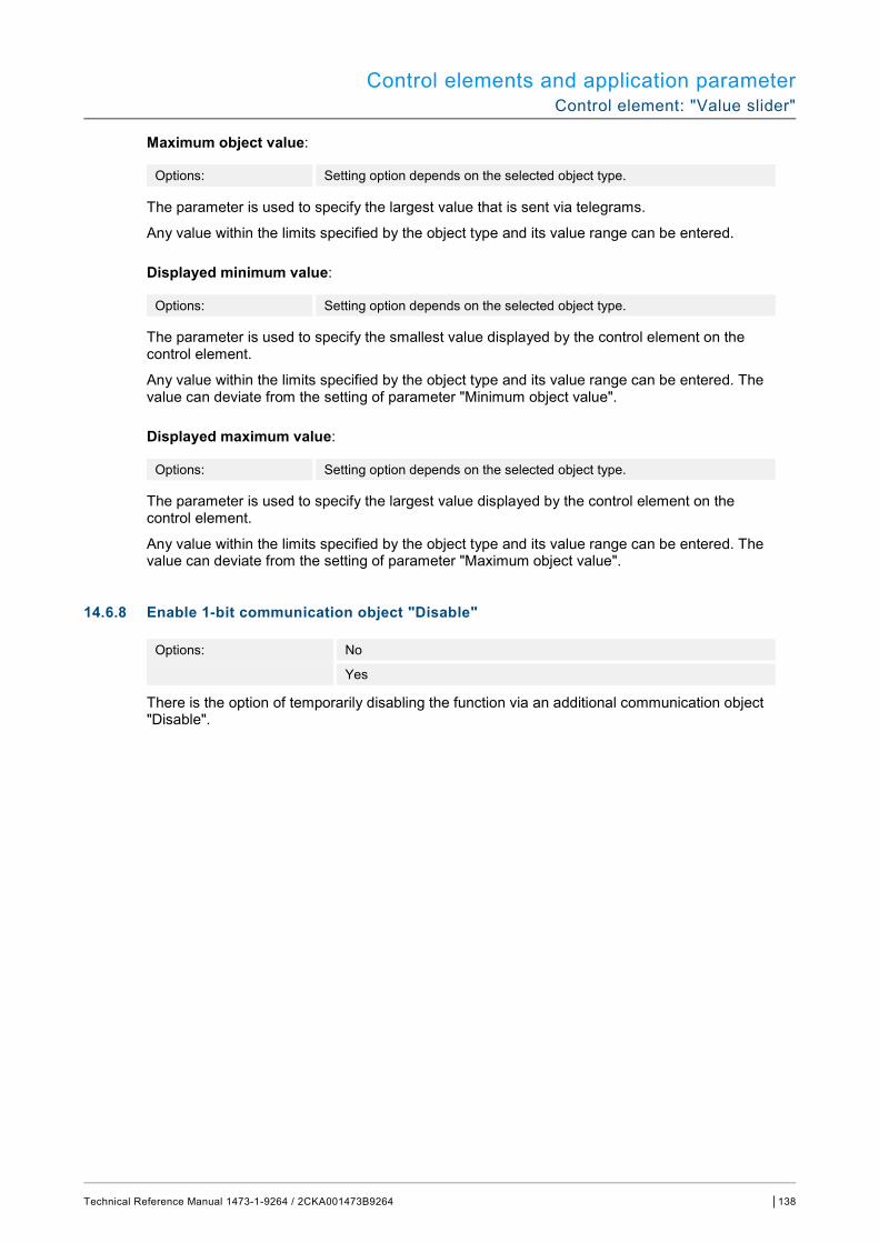
Control elements and application parameter Control element: "Value slider"
Technical Reference Manual 1473-1-9264 / 2CKA001473B9264 │138
Maximum object value:
Options: Setting option depends on the selected object type.
The parameter is used to specify the largest value that is sent via telegrams.
Any value within the limits specified by the object type and its value range can be entered.
Displayed minimum value:
Options: Setting option depends on the selected object type.
The parameter is used to specify the smallest value displayed by the control element on the control element.
Any value within the limits specified by the object type and its value range can be entered. The value can deviate from the setting of parameter "Minimum object value".
Displayed maximum value:
Options: Setting option depends on the selected object type.
The parameter is used to specify the largest value displayed by the control element on the control element.
Any value within the limits specified by the object type and its value range can be entered. The value can deviate from the setting of parameter "Maximum object value".
14.6.8 Enable 1-bit communication object "Disable"
Options: No
Yes
There is the option of temporarily disabling the function via an additional communication object "Disable".
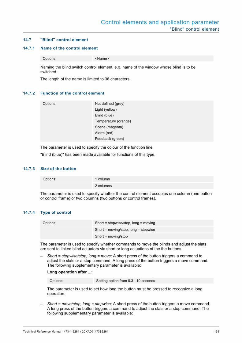
Control elements and application parameter "Blind" control element
Technical Reference Manual 1473-1-9264 / 2CKA001473B9264 │139
14.7 "Blind" control element
14.7.1 Name of the control element
Options: <Name>
Naming the blind switch control element, e.g. name of the window whose blind is to be switched.
The length of the name is limited to 36 characters.
14.7.2 Function of the control element
Options: Not defined (grey) Light (yellow) Blind (blue) Temperature (orange) Scene (magenta) Alarm (red) Feedback (green)
The parameter is used to specify the colour of the function line.
"Blind (blue)" has been made available for functions of this type.
14.7.3 Size of the button
Options: 1 column
2 columns
The parameter is used to specify whether the control element occupies one column (one button or control frame) or two columns (two buttons or control frames).
14.7.4 Type of control
Options: Short = stepwise/stop, long = moving
Short = moving/stop, long = stepwise
Short = moving/stop
The parameter is used to specify whether commands to move the blinds and adjust the slats are sent to linked blind actuators via short or long actuations of the the buttons.
– Short = stepwise/stop, long = move: A short press of the button triggers a command to adjust the slats or a stop command. A long press of the button triggers a move command. The following supplementary parameter is available:
Long operation after ...:
Options: Setting option from 0.3 - 10 seconds
The parameter is used to set how long the button must be pressed to recognize a long operation.
– Short = move/stop, long = stepwise: A short press of the button triggers a move command. A long press of the button triggers a command to adjust the slats or a stop command. The following supplementary parameter is available:
Control elements and application parameter "Blind" control element
Technical Reference Manual 1473-1-9264 / 2CKA001473B9264 │140
Long operation after ...:
Options: Setting option from 0.3 - 10 seconds
The parameter is used to set how long the button must be pressed to recognize a long operation.
Repeat of all "Stepwise/stop" telegrams:
Options: Setting option from 0.3 - 10 seconds
The parameter is used to set the space of time between two "Stepwise/stop" telegrams.
– Short = move/stop: At each short actuation the following commands are sent consecutively to linked blind actuators: ■ Move command ■ Stop command ■ Move command ■ Stop command ■ etc.
14.7.5 Icon type
Options: Blind animation
Shutter animation
Marquee animation
Hang animation
User-defined
The parameter is used to set whether a standard icon or a self-selected icon ("user-defined") is displayed.
The following supplementary parameters are available for all options:
Position for up/open icon:
Options: Left
Right
The parameter is used to specify whether the icon for "Up/Open" is positioned on the right or left side of the control element.
Icon for up/open:
Options: <Selection of an icon from the list>
The parameter is used to select the icon that is to be displayed in the control element for "Up/Open".
Icon for Down/Close:
Options: <Selection of an icon from the list>
The parameter is used to select the icon that is to be displayed in the control element for "Down/Close".
The following parameters can only be set when parameter "Icon type" is set on "User-defined".

Control elements and application parameter "Blind" control element
Technical Reference Manual 1473-1-9264 / 2CKA001473B9264 │141
Icon for opened:
Options: <Selection of an icon from the list>
The parameter is used to select the icon that is to be displayed when the blind is open.
Icon for closed:
Options: <Selection of an icon from the list>
The parameter is used to select the icon that is to be displayed when the blind is closed.
Icon for intermediate position:
Options: <Selection of an icon from the list>
The parameter is used to select the icon that is to be displayed when the blind is in an intermediate position.
14.7.6 Status control element (icon) is operated via a separate object
Options: No
Yes
An additional 1-bit communication object "Switch status" is enabled via the parameter.
– No: The communication object is not available. – Yes: The status display of the control element indicates the current status of the object. The
feedback object can ensure that the correct status is always displayed. If an actuator has a separate feedback object, this additional object can check whether the
actuator has switched. For this the feedback object of the actuator must be connected with the feedback object of the button via a common group address (Action).
If the status display is not activated via a feedback object, the control element always changes to the other status when actuated.
The following supplementary parameter is available for selection "Yes": Type of feedback signal:
Options: 1 bit
2x1 Bit
1 byte [0 - 100%]
1 byte [0 - 255]
The parameter is used to specify what the feedback object sends back.
14.7.7 Enable 1-bit communication object "Disable"
Options: No
Yes
There is the option of temporarily disabling the function via an additional communication object "Disable".

Control elements and application parameter Control element "Fan switch"
Technical Reference Manual 1473-1-9264 / 2CKA001473B9264 │142
14.8 Control element "Fan switch"
14.8.1 Name of the control element
Options: <Name>
Naming the fan switch control element, e.g. name of the fan that is to be controlled.
The length of the name is limited to 36 characters.
14.8.2 Function of the control element
Options: Not defined (grey) Light (yellow) Blind (blue) Temperature (orange) Scene (magenta) Alarm (red) Feedback (green)
The parameter is used to specify the colour of the function line.
"Temperature (orange)" has been made available for functions of this type.
14.8.3 Size of the button
Options: 1 column
2 columns
The parameter is used to specify whether the control element occupies one column (one button or control frame) or two columns (two buttons or control frames).
14.8.4 Deactivation of switch-off option
Options: No
Yes
The parameter is used to specify whether the ventilation control can be completely switched off.
Control elements and application parameter Control element "Fan switch"
Technical Reference Manual 1473-1-9264 / 2CKA001473B9264 │143
14.8.5 Icon type
Options: standard
User-defined
The parameter is used to set whether a standard icon or a self-selected icon ("user-defined") is displayed.
The following supplementary parameters are available for all options:
Position of the Up icon:
Options: Left
Right
The parameter is used to specify whether the icon for "Up" (Switching the fan speed level up) is positioned on the right or left side of the control element.
Icon for Up:
Options: <Selection of an icon from the list>
The parameter is used to select the icon that is to be displayed in the control element for switching the fan speed level up.
Icon for Down:
Options: <Selection of an icon from the list>
The parameter is used to select the icon that is to be displayed in the control element for switching the fan speed level down.
The following parameter can only be set when parameter "Icon type" is set on "User-defined".
Icon for On:
Options: <Selection of an icon from the list>
The parameter is used to select the icon that is to be displayed when the fan is switched on.
The following parameter can only be set when parameter "Icon type" is set on "User-defined" and the parameter "Deactivation of switch-off option" is set on "No".
Icon for Off:
Options: <Selection of an icon from the list>
The parameter is used to select the icon that is to be displayed when the fan is switched off.
14.8.6 Telegram is repeated every [sec.]:
Options: Setting option from 0.25 - 1.25 seconds
The parameter is used to specify the space of time between two telegrams.
Control elements and application parameter Control element "Fan switch"
Technical Reference Manual 1473-1-9264 / 2CKA001473B9264 │144
14.8.7 Number of speed levels
Options: Setting option from 1 - 8
The parameter is used to specify the number of fan speed levels that are available and can be switched.
14.8.8 Object type
Options: 1 bit [0/1]
1 byte unsigned [0 - 255]
When actuated the control element can send telegrams via the associated communication object. Parameter "Object type" is used to specify the size of the communication object.
– 1 bit [0/1]: Switching commands are sent with 1 bit (0 or 1), e.g. for switching a fan actuator (fan coil actuator). The following supplementary parameters are available: Also sending bits with value 0:
Options: No
Yes
The parameter is used to specify whether also switching commands with value "0" are sent. Switch pattern:
Options: 1 of n
x of n
Grey code
The parameter is used to specify how the fan is switched. – 1 off n: The speed level values ("0 - 3" or "0 - 5") are output via 1-bit objects. Available
are as many 1-bit objects as fan speed levels, e.g. for speed level "2" the fan speed level object "2" is output with value "1". The other fan speed level objects are output with value "0". (For 5 objects, object 1 to 5):
00000 10000 01000 00100 00010 00001
– x off n: The speed level values ("0 - 3" or "0 - 5") are output via 1-bit objects. Available are as many 1-bit objects as fan speed levels, e.g. for speed level "2" the fan speed level objects "1" and "2" are output with value "1". The other fan speed level objects are output with value "0". x of n (For 5 objects, object 1 to 5):
00000 > send all objects "0" 10000 > Object 1 sends "1" (also sends the 0 bit =Yes), objects 2 to 5 send "0" 11000 > Objects 1 and 2 send "1", objects 3 to 5 send "0" 11100 etc. 11110 11111

Control elements and application parameter Control element "Fan switch"
Technical Reference Manual 1473-1-9264 / 2CKA001473B9264 │145
– Grey code: For 5 objects, object 1 to 5:
00000 01100 00110 10000 11100 etc. 01000 00010 11000 10010 00100 01010 10100 11010
– 1-byte unsigned [0 - 255]: A value is sent as 1-byte value without a sign, e.g. actuating value. The value can be sent for each level. The following supplementary parameters are available: Value Off:
Options: Setting option from 0 - 255
The parameter is used to set which 1-byte value is to be sent.
Note The following parameter is only available when parameter "Deactivation of switch-off option" is set on "No".
Value level x (1 - 8):
Options: Setting option from 0 - 255
The parameter is used to set for which level the value is to be sent.
Note How many "Value level x" parameters are available depends on the setting of the "Number of levels" parameter.
14.8.9 Display status
Options: User-defined
Standard
No
The parameter is used to specify which status texts are displayed for the individual switching levels.
– User-defined: User-defined texts are displayed for the individual switching levels. The following supplementary parameters are available: Text Off:
Options: <Text for "Off">
The parameter is used to specify the text that is to be displayed when the fan is switched off. The length of the text is limited to 15 characters.
Note The following parameter is only available when parameter "Deactivation of switch-off option" is set on "No".

Control elements and application parameter Control element "Fan switch"
Technical Reference Manual 1473-1-9264 / 2CKA001473B9264 │146
Text level x (1 - 8):
Options: <Text for switching level>
The parameter is used to specify the text that is sent for the respective level. The length of the text is limited to 15 characters.
Note How many "Text level x" parameters are available depends on the setting of the "Number of levels" parameter.
Text beyond reach:
Options: <Text for "beyond reach">
The parameter is used to specify the text that is displayed when the user-defined texts are too long. The length of the text is limited to 15 characters.
– Standard: Standard texts are displayed for the individual switching levels. The following supplementary parameter is available: Text beyond reach:
Options: <Text for "beyond reach">
The parameter is used to specify the text that is displayed when the standard texts are too long. The length of the text is limited to 15 characters.
– No: No texts are displayed.
14.8.10 Enable 1-bit communication object "Disable"
Options: No
Yes
There is the option of temporarily disabling the function via an additional communication object "Disable".
Control elements and application parameter "Scene" control element
Technical Reference Manual 1473-1-9264 / 2CKA001473B9264 │147
14.9 "Scene" control element
14.9.1 Name of the control element
Options: <Name>
Naming of the scene control element.
The length of the name is limited to 36 characters.
14.9.2 Function of the control element
Options: Not defined (grey) Light (yellow) Blind (blue) Temperature (orange) Scene (magenta) Alarm (red) Feedback (green)
The parameter is used to specify the colour of the function line.
"Scene (magenta)" has been made available for functions of this type.
14.9.3 Start scene at selection
Options: No
Yes
The parameter is used to specify whether the scene is executed directly with a click on the control element or whether it must be started again separately.
14.9.4 Long operation after...
Options: Setting option from 0.3 - 10 seconds
The parameter is used to specify how long the button must be pressed to recognize a long operation.
14.9.5 Number of scenes [1 - 10]
Options: Setting option from 1 - 10
The parameter is used to specify the number of scenes available in the selection list.

Control elements and application parameter "Scene" control element
Technical Reference Manual 1473-1-9264 / 2CKA001473B9264 │148
14.9.6 Scene number x [1 - 64]
Options: Setting option from 1 - 64
The parameter is used to specify which scenes are to be started.
Note How many "Scene number x [1 - 64]" parameters are available depends on the setting of the "Number of scenes [1 - 10]" parameter.
14.9.7 Name of scene x
Options: <Name>
Designation of scene. The length of the name is limited to 60 characters.
Note How many "Name of scene x" parameters are available depends on the setting of the "Number of scenes [1 - 10]" parameter.
14.9.8 Saving scene x with a long press
Options: No
Yes
The parameter is used to specify whether the scene x can be saved only with a long press of the button. For setting the press of the button see parameter "Long operation after...".
Note How many "Save scene x with a long press" parameters are available depends on the setting of the "Number of scenes [1 - 10]" parameter.
14.9.9 Enable 1-bit communication object "Disable"
Options: No
Yes
There is the option of temporarily disabling the function via an additional communication object "Disable".

Control elements and application parameter "Display" control element
Technical Reference Manual 1473-1-9264 / 2CKA001473B9264 │149
14.10 "Display" control element
14.10.1 Name of the control element
Options: <Name>
Naming of the display control element.
The length of the name is limited to 36 characters.
14.10.2 Function of the control element
Options: Not defined (grey) Light (yellow) Blind (blue) Temperature (orange) Scene (magenta) Alarm (red) Feedback (green)
The parameter is used to specify the colour of the function line.
"Not defined (grey)" has been made available for functions of this type.
14.10.3 Type of display element
Options: Status display Value display Linear measurement display Round measurement display Wind rose Wind force Temperature Rain Twilight Brightness CO2 Moisture Air pressure
– Status display: The status of an allocated element is displayed as text. – Value display: The value of an allocated element is displayed. – Linear measurement display: The measured values of an allocated element are displayed in
linear form. – Round measurement display: The measured values of an allocated element are displayed in
round form. – Wind rose: The measured values (wind direction) of an allocated element are displayed as
wind rose. – Wind force: The wind force values of an allocated element are displayed. – Temperature: The temperature values of an allocated element are displayed. – Rain: The rain values of an allocated element are displayed.
Control elements and application parameter "Display" control element
Technical Reference Manual 1473-1-9264 / 2CKA001473B9264 │150
– Twilight: The twilight values of an allocated element are displayed. – Brightness: The brightness values of an allocated element are displayed. – CO2: The carbon dioxide values of an allocated element are displayed. – Moisture: The moisture values of an allocated element are displayed. – Air pressure: The air pressure values of an allocated element are displayed.
Note Supplementary parameters are available for all options. The parameter that are displayed depends on the setting of the "Type of display element" parameter.
14.10.4 Type of display element — Status display — Size of the button
Options: 1 column
2 columns
The parameter is used to specify whether the display element occupies one column (one button or control frame) or two columns (two buttons or control frames).
14.10.5 Type of display element — Status display — Object type
Options: 1 bit
1-byte value [0 - 255]
Parameter "Object type" is used to specify the size of the communication object.
– 1 bit: Status commands are sent with 1 bit (0 or 1). The following supplementary parameters are available: Text for value 0:
Options: <text>
The parameter is used to specify the text that is displayed for value 0. The length of the text is limited to 60 characters.
Text for value 1:
Options: <text>
The parameter is used to specify the text that is displayed for value 1. The length of the text is limited to 60 characters.
– 1-byte value [0 - 255]: A status value is sent as 1-byte value without a sign. The following supplementary parameters are available: Text x for value [0 - 255]:
Options: Setting option from 0 - 255
The parameter is used to set the status value at which text x is displayed.
Note 8 parameters "Text x at value [0 - 255]" are available which can be set as required.
Control elements and application parameter "Display" control element
Technical Reference Manual 1473-1-9264 / 2CKA001473B9264 │151
Text x:
Options: <text>
The parameter is used to specify the text that is displayed. The length of the text is limited to 60 characters.
Note 8 parameters "Text x" are available which can be set as required.
14.10.6 Type of display element — Value display — Size of the button
Options: 1 column
2 columns
The parameter is used to specify whether the display element occupies one column (one button or control frame) or two columns (two buttons or control frames).
14.10.7 Type of display element — Value display — Object type
Options: 1-byte value [0% - 100%]
1-byte value [0 - 255]
1-byte value [-128 - 127]
2-byte value [0 - 65535]
2-byte value [-32768 - +32767]
2-byte floating point
4-byte value [0 - 4294967295]
4-byte value [-2147483648 - 2147483647]
14-byte text
Parameter "Object type" is used to specify the size of the communication object.
– 1-byte value [0% - 100%]: A value is sent as 1-byte value without a sign (percentage value). – 1-byte value [0 - 255]: A value is sent as 1-byte value without a sign, e.g. actuating value,
angle or brightness value. – 1-byte value [-128 - 127]: A value is sent as 1-byte value with a sign, e.g. actuating value. – 2-byte value [0 - 65535]: A value is sent as 2-byte value without a sign, e.g. actuating value
or time interval. – 2-byte value [-32768 - +32767]: A value is sent as 2-byte value with a sign, e.g. actuating
value or time difference. – 2-byte floating point: A value is sent as 2-byte floating point value, e.g. a temperature value,
a time duration, a performance or a consumption value. – 4-byte value [0 - 4294967295]: A value is sent as 4-byte value without a sign, e.g. actuating
value. – 4-byte value [-2147483648 - 2147483647]: A value is sent as 4-byte value with a sign, e.g.
actuating value or time difference. – 14-byte value: Makes it possible to send any text with a maximum of 14 characters.
Control elements and application parameter "Display" control element
Technical Reference Manual 1473-1-9264 / 2CKA001473B9264 │152
The following supplementary parameters are available for all options, except for option "14-byte value":
Note Different values can be preset or set, depending on the selected option.
Unit:
Options: <text>
The parameter is used to enter the unit or the unit sign with which the value is displayed in the display element.
The length of the text is limited to 60 characters.
Decimal places:
Options: Setting option from 0 - 2
The parameter is used to specify the number of decimal places of the displayed value. The number is limited to 2 places.
Thousands separator:
Options: No
Yes
The parameter is used to specify whether a thousands separator is displayed in the value.
Minimum object value:
Options: Setting option depends on the selected object type.
The parameter is used to specify the smallest value that is sent via telegrams to the display element.
Any value within the limits specified by the object type and its value range can be entered.
Maximum object value:
Options: Setting option depends on the selected object type.
The parameter is used to specify the largest value that is sent via telegrams to the display element.
Any value within the limits specified by the object type and its value range can be entered.
Displayed minimum value:
Options: Setting option depends on the selected object type.
The parameter is used to specify the smallest value that is displayed in the display element.
Any value within the limits specified by the object type and its value range can be entered. The value can deviate from the setting of parameter "Minimum object value".
Control elements and application parameter "Display" control element
Technical Reference Manual 1473-1-9264 / 2CKA001473B9264 │153
Displayed maximum value:
Options: Setting option depends on the selected object type.
The parameter is used to specify the largest value that is displayed in the display element.
Any value within the limits specified by the object type and its value range can be entered. The value can deviate from the setting of parameter "Maximum object value".
14.10.8 Type of display element — Linear measurement display — Measurement display with colour display
Options: No
Yes
The parameter is used to specify whether a colour display follows. For this the communication object "Switch alarm", "Switch warning", and "Switch information" are enabled.
14.10.9 Type of display element — Linear measurement display — Display value in control element
Options: No
Yes
The parameter is used to specify whether the value of the selected element is displayed in the display element.
– No: No display. No additional parameters available. – Yes: The following supplementary parameters are displayed:
Unit:
Options: <text>
The parameter is used to enter the unit or the unit sign with which the measured value is displayed in the display element.
The length of the text is limited to 60 characters. Decimal places:
Options: Setting option from 0 - 2
The parameter is used to specify the number of decimal places of the displayed measured value.
The number is limited to 2 places. Thousands separator:
Options: No
Yes
The parameter is used to specify whether a thousands separator is displayed in the measured value.
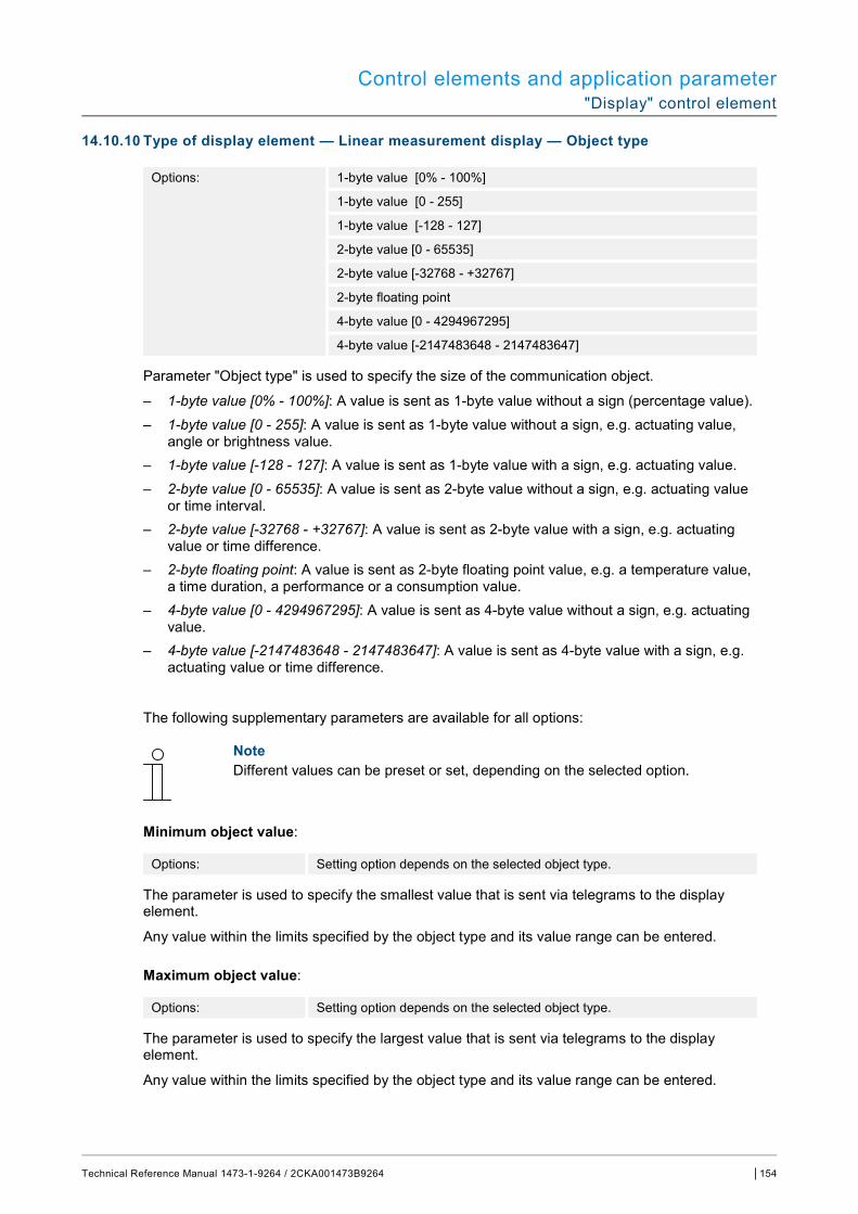
Control elements and application parameter "Display" control element
Technical Reference Manual 1473-1-9264 / 2CKA001473B9264 │154
14.10.10 Type of display element — Linear measurement display — Object type
Options: 1-byte value [0% - 100%]
1-byte value [0 - 255]
1-byte value [-128 - 127]
2-byte value [0 - 65535]
2-byte value [-32768 - +32767]
2-byte floating point
4-byte value [0 - 4294967295]
4-byte value [-2147483648 - 2147483647]
Parameter "Object type" is used to specify the size of the communication object.
– 1-byte value [0% - 100%]: A value is sent as 1-byte value without a sign (percentage value). – 1-byte value [0 - 255]: A value is sent as 1-byte value without a sign, e.g. actuating value,
angle or brightness value. – 1-byte value [-128 - 127]: A value is sent as 1-byte value with a sign, e.g. actuating value. – 2-byte value [0 - 65535]: A value is sent as 2-byte value without a sign, e.g. actuating value
or time interval. – 2-byte value [-32768 - +32767]: A value is sent as 2-byte value with a sign, e.g. actuating
value or time difference. – 2-byte floating point: A value is sent as 2-byte floating point value, e.g. a temperature value,
a time duration, a performance or a consumption value. – 4-byte value [0 - 4294967295]: A value is sent as 4-byte value without a sign, e.g. actuating
value. – 4-byte value [-2147483648 - 2147483647]: A value is sent as 4-byte value with a sign, e.g.
actuating value or time difference.
The following supplementary parameters are available for all options:
Note Different values can be preset or set, depending on the selected option.
Minimum object value:
Options: Setting option depends on the selected object type.
The parameter is used to specify the smallest value that is sent via telegrams to the display element.
Any value within the limits specified by the object type and its value range can be entered.
Maximum object value:
Options: Setting option depends on the selected object type.
The parameter is used to specify the largest value that is sent via telegrams to the display element.
Any value within the limits specified by the object type and its value range can be entered.
Control elements and application parameter "Display" control element
Technical Reference Manual 1473-1-9264 / 2CKA001473B9264 │155
Displayed minimum value:
Options: Setting option depends on the selected object type.
The parameter is used to specify the smallest value that is displayed in the display element.
Any value within the limits specified by the object type and its value range can be entered. The value can deviate from the setting of parameter "Minimum object value".
Displayed maximum value:
Options: Setting option depends on the selected object type.
The parameter is used to specify the largest value that is displayed in the display element.
Any value within the limits specified by the object type and its value range can be entered. The value can deviate from the setting of parameter "Maximum object value".
14.10.11 Type of display element — Round measurement display
Note For option "Round measurement display" of parameter "Type of display element" the same supplementary parameters are available, such as for option "Linear measurement display", see chapter 15.10.8 “Type of display element — Linear measurement display — Measurement display with colour display“ on page 153.
14.10.12 Type of display element — Wind rose
Note For option "Wind rose" of parameter "Type of display element" the same supplementary parameters are available, such as for option "Linear measurement display", see chapter 15.10.8 “Type of display element — Linear measurement display — Measurement display with colour display“ on page 153. Parameter "Measurement display with colour display" is not available.
14.10.13 Type of display element — Wind force — Size of the button
Options: 1 column
2 columns
The parameter is used to specify whether the display element occupies one column (one button or control frame) or two columns (two buttons or control frames).

Control elements and application parameter "Display" control element
Technical Reference Manual 1473-1-9264 / 2CKA001473B9264 │156
14.10.14 Type of display element — Wind force — Unit
Options: m/s
Bft
km/h
The parameter is used to specify the unit with which the wind force is displayed in the display element.
14.10.15 Type of display element — Temperature — Size of the button
Options: 1 column
2 columns
The parameter is used to specify whether the display element occupies one column (one button or control frame) or two columns (two buttons or control frames).
14.10.16 Type of display element — Temperature — Unit
Options: °C
°F
The parameter is used to specify the unit with which the temperature is displayed in the display element.
14.10.17 Type of display element — Rain — Size of the button
Options: 1 column
2 columns
The parameter is used to specify whether the display element occupies one column (one button or control frame) or two columns (two buttons or control frames).
14.10.18 Type of display element — Rain — Text for rain
Options: <text>
The parameter is used to specify the text that is displayed for rain.
The length of the text is limited to 60 characters.
14.10.19 Type of display element — Rain — Text for no rain
Options: <text>
The parameter is used to specify the text that is displayed for dry weather.
The length of the text is limited to 60 characters.

Control elements and application parameter "Display" control element
Technical Reference Manual 1473-1-9264 / 2CKA001473B9264 │157
14.10.20 Type of display element — Twilight — Size of the button
Options: 1 column
2 columns
The parameter is used to specify whether the display element occupies one column (one button or control frame) or two columns (two buttons or control frames).
14.10.21 Type of display element — Twilight — Unit
Options: Lux
kLux
The parameter is used to specify the unit with which the twilight is displayed in the display element.
14.10.22 Type of display element — Brightness
Note For option "Brightness" of parameter "Type of display element" the same supplementary parameters are available, such as for option "Twilight".
14.10.23 Type of display element — CO2 — Size of the button
Options: 1 column
2 columns
The parameter is used to specify whether the display element occupies one column (one button or control frame) or two columns (two buttons or control frames).
14.10.24 Type of display element — CO2 — Unit
Options: Fixed at ppm
The parameter is used to specify the unit with which the concentration of carbon dioxide (CO2) in the air is displayed in the display element.
14.10.25 Type of display element — Moisture — Size of the button
Options: 1 column
2 columns
The parameter is used to specify whether the display element occupies one column (one button or control frame) or two columns (two buttons or control frames).
Control elements and application parameter "Display" control element
Technical Reference Manual 1473-1-9264 / 2CKA001473B9264 │158
14.10.26 Type of display element — Moisture — Unit
Options: Fixed at %
The parameter is used to specify the unit with which the moisture is displayed in the display element.
14.10.27 Type of display element — Air pressure — Size of the button
Options: 1 column
2 columns
The parameter is used to specify whether the display element occupies one column (one button or control frame) or two columns (two buttons or control frames).
14.10.28 Type of display element — Air pressure — Unit
Options: Fixed at Pa
The parameter is used to specify the unit with which the air pressure is displayed in the display element.
14.10.29 Enable 1-bit communication object "Disable"
Options: No
Yes
There is the option of temporarily disabling the function via an additional communication object "Disable".
Control elements and application parameter Control element "RTC control element"
Technical Reference Manual 1473-1-9264 / 2CKA001473B9264 │159
14.11 Control element "RTC control element"
14.11.1 Name of the control element
Options: <Name>
Naming of the RTC control element.
The length of the name is limited to 36 characters.
14.11.2 Function of the control element
Options: Not defined (grey) Light (yellow) Blind (blue) Temperature (orange) Scene (magenta) Alarm (red) Feedback (green)
The parameter is used to specify the colour of the function line.
"Temperature (orange)" has been made available for functions of this type.
14.11.3 Additional functions/objects
Options: No
Yes
The parameter is used to specify whether parameter "Delay time during reading of telegrams after reset [sec.]" is displayed.
14.11.4 Delay time during reading of telegrams after reset [sec.]
Options: Setting option from 1 - 255 seconds
The parameter is used to specify the number of seconds telegrams are delayed after a reset..
Note The parameter can only be set when parameter "Additional functions/objects" is set on "Yes".

Control elements and application parameter Control element "RTC control element"
Technical Reference Manual 1473-1-9264 / 2CKA001473B9264 │160
14.11.5 Input for temperature reading
Options: Internal measurement
External measurement
The parameter is used to specify whether the temperature is read via an internal or external temperature sensor.
– Internal measurement: The following supplementary parameters are available: Cyclic sending of the current actual temperature [min.]:
Options: Setting option from 5 - 240
The parameter is used to set the time intervals at which current temperature used by the device is sent to the bus.
Difference of value for sending the actual temperature [x 0.1°C]: Options: Setting option from 1 - 100
The parameter is used to set the temperature difference from which the current temperature is to be sent. The temperature difference is calculated from the measured temperature and the actual temperature sent last. Compensating value for internal temperature measurement [x 0.1°C]:
Options: Setting option from -127 - +127
Each installation site exhibits different physical conditions, e.g. interior or exterior wall, lightweight or solid wall. To ensure that the device displays the correct temperature, measure the current temperature at the installation site with an aligned and/or calibrated thermometer. The parameter is used to specify the difference between thermometer and the actual temperature displayed on the device as "Adjustment value".
Note To prevent faulty measurements, carry out the adjustment measurement only after the device has adjusted itself to he environmental temperature. It is recommended to repeat the adjustment measurement just prior to or after occupying the room.
– External measurement: No additional parameters available.
14.11.6 Display actual temperature
Options: No
Yes
The parameter is used to specify whether the current temperature is displayed.
14.11.7 Temperature unit
Options: °C
°F
The parameter is used to specify the unit with which the temperature is displayed.
Control elements and application parameter Control element "RTC control element"
Technical Reference Manual 1473-1-9264 / 2CKA001473B9264 │161
14.11.8 Set value is relative
Options: No
Yes
The parameter is used to specify whether the set value for devices with display is displayed as relative value, e.g. -5°C - +5°C.
14.11.9 Heating/cooling switchover
Options: No
Yes
The parameter is used to specify whether the RTC control element can be switched over between heating and cooling mode.
14.11.10 Fan coil control during heating mode
Options: No
Yes
The parameter is used to specify whether the fan coil fan is activated during heating mode.
14.11.11 Fan coil control during cooling mode
Options: No
Yes
The parameter is used to specify whether the fan coil fan is activated during cooling mode.
14.11.12 Setting the temperature unit via object
Options: No
Yes
The parameter is used to specify whether it is possible to set the temperature unit via a communication object.
14.11.13 Enable 1-bit communication object "Disable"
Options: No
Yes
There is the option of temporarily disabling the function via an additional communication object "Disable".
Control elements and application parameter "Page link" control element
Technical Reference Manual 1473-1-9264 / 2CKA001473B9264 │162
14.12 "Page link" control element
14.12.1 Name of the control element
Options: <Name>
Naming of the page link control element.
The length of the name is limited to 36 characters.
14.12.2 Function of the control element
Options: Not defined (grey) Light (yellow) Blind (blue) Temperature (orange) Scene (magenta) Alarm (red) Feedback (green)
The parameter is used to specify the colour of the function line.
"Not defined (grey)" has been made available for functions of this type.
14.12.3 Size of the button
Options: 1 column
2 columns
The parameter is used to specify whether the control element occupies one column (one button or control frame) or two columns (two buttons or control frames).
14.12.4 Linked with page
Options: <Main operating page>
<Operating page x>
<Application page x>
The parameter is used to specify with which operating or application page the page link control element is linked.
– <Main operating page>: Start page or homepage. – <Operating page x>: All operating pages (start pages and operating pages for rooms) which
were created via the commissioning tool can be selected. – <Application page x>: The following application pages can be selected: system settings,
door communication, fault and alarm messages or time programs.
Control elements and application parameter "Page link" control element
Technical Reference Manual 1473-1-9264 / 2CKA001473B9264 │163
14.12.5 Enable 1-bit communication object "Disable"
Options: No
Yes
There is the option of temporarily disabling the function via an additional communication object "Disable".

Control elements and application parameter Control element "Audio control"
Technical Reference Manual 1473-1-9264 / 2CKA001473B9264 │164
14.13 Control element "Audio control"
14.13.1 Name of the control element
Options: <Name>
Naming of the control element for audio control.
The length of the name is limited to 36 characters.
14.13.2 Function of the control element
Options: Not defined (grey) Light (yellow) Blind (blue) Temperature (orange) Scene (magenta) Alarm (red) Feedback (green)
The parameter is used to specify the colour of the function line.
"Not defined (grey)" has been made available for functions of this type.
14.13.3 Number of sources
Options: Setting option from 0 - 8
The parameter is used to set how many audio sources are enabled.
– 0: No audio sources are enabled. No additional parameters available. – 1 - 8: The following supplementary parameters are available:
Source x Name:
Options: <Name>
Designation of audio source. The length of the name is limited to 40 characters. Source x type:
Options: 1 bit
1-byte value [0 - 255]
The parameter is used to specify the size of the communication object. – 1 bit: Commands are sent to an audio source with 1 bit (0 or 1). No additional
parameters available. – 1-byte value [0 - 255]: The value of an audio source is sent as 1-byte value without a
sign. The following supplementary parameter is available: Source x value:
Options: Setting option from 0 - 255
The parameter is used to send the value per source.
Control elements and application parameter Control element "Audio control"
Technical Reference Manual 1473-1-9264 / 2CKA001473B9264 │165
14.13.4 Use of play button
Options: No
Yes
– No: No playback button is enabled. No additional parameters available. – Yes: The playback button is enabled. The following supplementary parameter is available:
Object type play button:
Options: 1 bit
1-byte value [0 - 255]
The parameter is used to specify the size of the communication object for sending telegrams. – 1 bit: Commands of a playback button are sent with 1 bit (0 or 1). The following
supplementary parameter is available: Value for play:
Options: 0 1
The parameter is used to send the command of the playback button with "0" or "1".
– 1-byte value [0 - 255]: The value of an playback button is sent as 1-byte value without a sign. The following supplementary parameter is available: Value for play:
Options: Setting option from 0 - 255
The parameter is used to send the value of the playback button as absolute value.
14.13.5 Use of pause button
Options: No
Yes
– No: No pause button is enabled. No additional parameters available. – Yes: The pause button is enabled. The following supplementary parameter is available:
Object type pause button:
Options: 1 bit
1-byte value [0 - 255]
The parameter is used to specify the size of the communication object for sending telegrams. – 1 bit: Commands of a pause button are sent with 1 bit (0 or 1). The following
supplementary parameter is available: Value for pause:
Options: 0 1
The parameter is used to send the command of the pause button with "0" or "1".
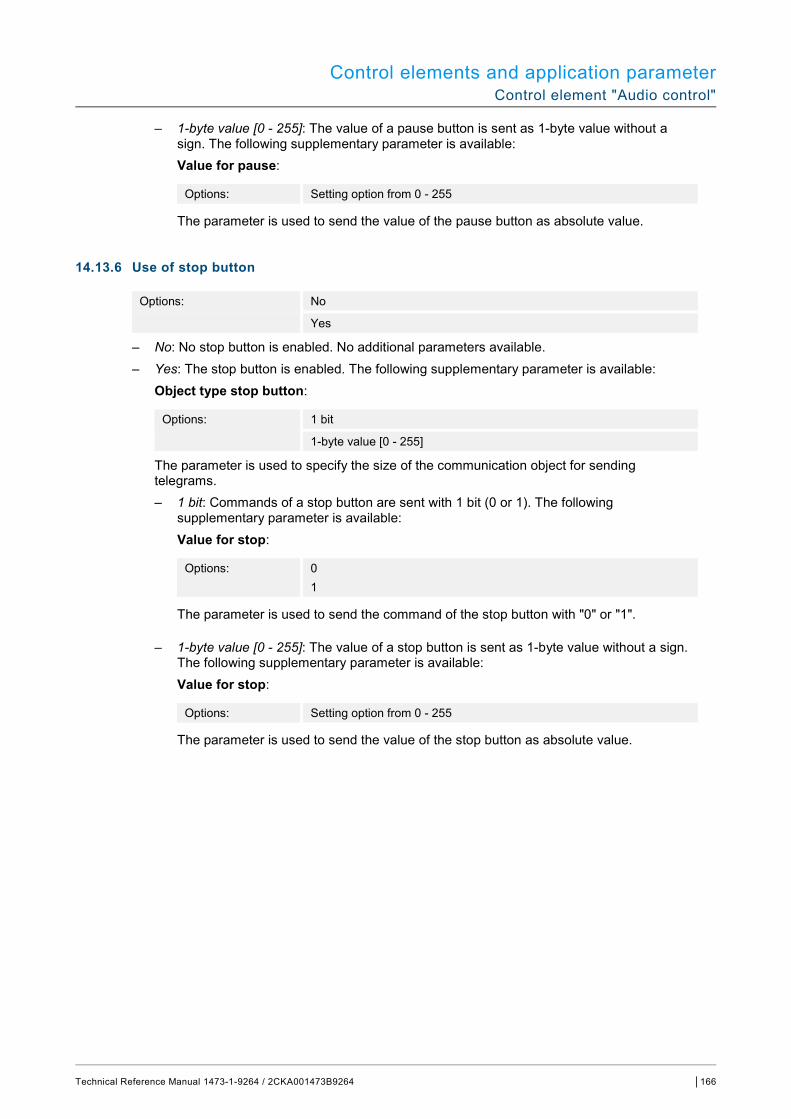
Control elements and application parameter Control element "Audio control"
Technical Reference Manual 1473-1-9264 / 2CKA001473B9264 │166
– 1-byte value [0 - 255]: The value of a pause button is sent as 1-byte value without a sign. The following supplementary parameter is available: Value for pause:
Options: Setting option from 0 - 255
The parameter is used to send the value of the pause button as absolute value.
14.13.6 Use of stop button
Options: No
Yes
– No: No stop button is enabled. No additional parameters available. – Yes: The stop button is enabled. The following supplementary parameter is available:
Object type stop button:
Options: 1 bit
1-byte value [0 - 255]
The parameter is used to specify the size of the communication object for sending telegrams. – 1 bit: Commands of a stop button are sent with 1 bit (0 or 1). The following
supplementary parameter is available: Value for stop:
Options: 0 1
The parameter is used to send the command of the stop button with "0" or "1".
– 1-byte value [0 - 255]: The value of a stop button is sent as 1-byte value without a sign. The following supplementary parameter is available: Value for stop:
Options: Setting option from 0 - 255
The parameter is used to send the value of the stop button as absolute value.
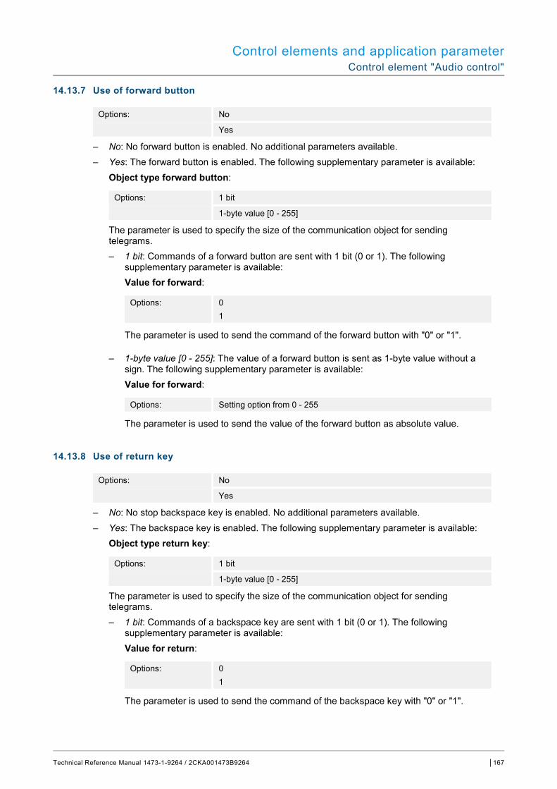
Control elements and application parameter Control element "Audio control"
Technical Reference Manual 1473-1-9264 / 2CKA001473B9264 │167
14.13.7 Use of forward button
Options: No
Yes
– No: No forward button is enabled. No additional parameters available. – Yes: The forward button is enabled. The following supplementary parameter is available:
Object type forward button:
Options: 1 bit
1-byte value [0 - 255]
The parameter is used to specify the size of the communication object for sending telegrams. – 1 bit: Commands of a forward button are sent with 1 bit (0 or 1). The following
supplementary parameter is available: Value for forward:
Options: 0 1
The parameter is used to send the command of the forward button with "0" or "1".
– 1-byte value [0 - 255]: The value of a forward button is sent as 1-byte value without a sign. The following supplementary parameter is available: Value for forward:
Options: Setting option from 0 - 255
The parameter is used to send the value of the forward button as absolute value.
14.13.8 Use of return key
Options: No
Yes
– No: No stop backspace key is enabled. No additional parameters available. – Yes: The backspace key is enabled. The following supplementary parameter is available:
Object type return key:
Options: 1 bit
1-byte value [0 - 255]
The parameter is used to specify the size of the communication object for sending telegrams. – 1 bit: Commands of a backspace key are sent with 1 bit (0 or 1). The following
supplementary parameter is available: Value for return:
Options: 0 1
The parameter is used to send the command of the backspace key with "0" or "1".
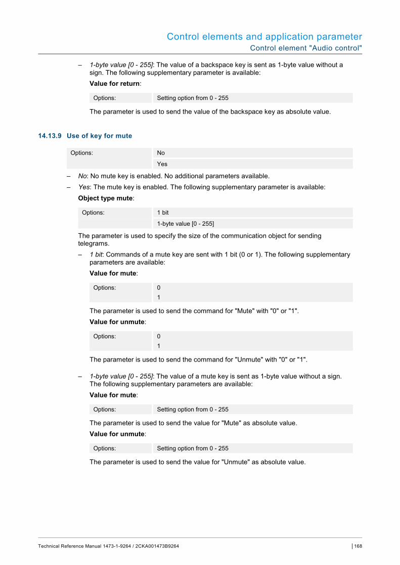
Control elements and application parameter Control element "Audio control"
Technical Reference Manual 1473-1-9264 / 2CKA001473B9264 │168
– 1-byte value [0 - 255]: The value of a backspace key is sent as 1-byte value without a sign. The following supplementary parameter is available: Value for return:
Options: Setting option from 0 - 255
The parameter is used to send the value of the backspace key as absolute value.
14.13.9 Use of key for mute
Options: No
Yes
– No: No mute key is enabled. No additional parameters available. – Yes: The mute key is enabled. The following supplementary parameter is available:
Object type mute:
Options: 1 bit
1-byte value [0 - 255]
The parameter is used to specify the size of the communication object for sending telegrams. – 1 bit: Commands of a mute key are sent with 1 bit (0 or 1). The following supplementary
parameters are available: Value for mute:
Options: 0 1
The parameter is used to send the command for "Mute" with "0" or "1". Value for unmute:
Options: 0 1
The parameter is used to send the command for "Unmute" with "0" or "1".
– 1-byte value [0 - 255]: The value of a mute key is sent as 1-byte value without a sign. The following supplementary parameters are available: Value for mute:
Options: Setting option from 0 - 255
The parameter is used to send the value for "Mute" as absolute value. Value for unmute:
Options: Setting option from 0 - 255
The parameter is used to send the value for "Unmute" as absolute value.

Control elements and application parameter Control element "Audio control"
Technical Reference Manual 1473-1-9264 / 2CKA001473B9264 │169
14.13.10 Use of volume key
Options: No
Yes
– No: No volume key is enabled. No additional parameters available. – Yes: The volume key is enabled. The following supplementary parameter is available:
Object type volume key:
Options: 2 x 1 Bit
1 x 4 Bit
1-byte value [0 - 100%]
The parameter is used to specify the size of the communication object for sending telegrams. – 2 x 1 bit: Commands of a volume key are sent with 2 x 1 bit (0 or 1). The following
supplementary parameters are available: Value for increase:
Options: 0 1
The parameter is used to send the command for "Increase volume" with "0" or "1". Value for decrease:
Options: 0 1
The parameter is used to send the command for "Decrease volume" with "0" or "1".
– 1 x 4 bit: Commands of a volume key are sent with 4 bit. No additional parameters available.
– 1-byte value [0 - 255]: The value of a volume key is sent as 1-byte value without a sign. The following supplementary parameters are available: Change of volume [%]:
Options: Setting option from 1 - 50
The parameter is used to specify in which step widths the volume is raised or lowered. Telegram is repeated every [sec.]:
Options: Setting option from 0.25 - 1.25 seconds
The parameter is used to specify the space of time between two telegrams.

Control elements and application parameter Control element "Audio control"
Technical Reference Manual 1473-1-9264 / 2CKA001473B9264 │170
14.13.11 Use of ON/OFF key
Options: No
Yes
– No: No ON/OFF key is enabled. No additional parameters available. – Yes: The ON/OFF key is enabled. The following supplementary parameter is available:
Object type ON/OFF key
Options: 1 bit
1-byte value [0 - 255]
The parameter is used to specify the size of the communication object for sending telegrams. – 1 bit: Commands of an ON/OFF key are sent with 1 bit (0 or 1). The following
supplementary parameters are available: Value for ON:
Options: 0 1
The parameter is used to send the command for "ON" with "0" or "1". Value for OFF:
Options: 0 1
The parameter is used to send the command for "OFF" with "0" or "1".
– 1-byte value [0 - 255]: The value of an ON/OFF key is sent as 1-byte value without a sign. The following supplementary parameters are available: Value for ON:
Options: Setting option from 0 - 255
The parameter is used to send the value for "ON" as absolute value. Value for OFF:
Options: Setting option from 0 - 255
The parameter is used to send the value for "OFF" as absolute value.
14.13.12 Enable 1-bit communication object "Disable"
Options: No
Yes
There is the option of temporarily disabling the function via an additional communication object "Disable".
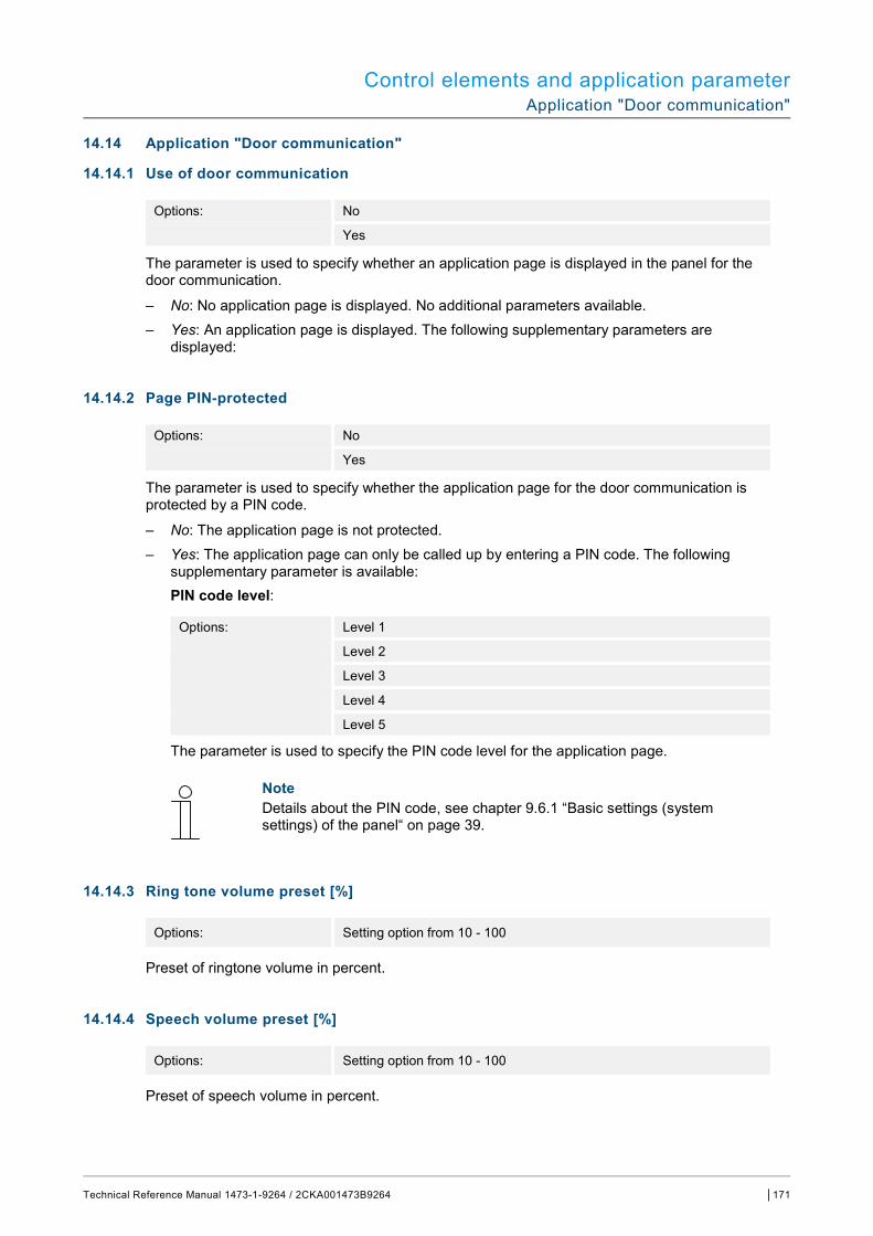
Control elements and application parameter Application "Door communication"
Technical Reference Manual 1473-1-9264 / 2CKA001473B9264 │171
14.14 Application "Door communication"
14.14.1 Use of door communication
Options: No
Yes
The parameter is used to specify whether an application page is displayed in the panel for the door communication.
– No: No application page is displayed. No additional parameters available. – Yes: An application page is displayed. The following supplementary parameters are
displayed:
14.14.2 Page PIN-protected
Options: No
Yes
The parameter is used to specify whether the application page for the door communication is protected by a PIN code.
– No: The application page is not protected. – Yes: The application page can only be called up by entering a PIN code. The following
supplementary parameter is available: PIN code level:
Options: Level 1
Level 2
Level 3
Level 4
Level 5
The parameter is used to specify the PIN code level for the application page.
Note Details about the PIN code, see chapter 9.6.1 “Basic settings (system settings) of the panel“ on page 39.
14.14.3 Ring tone volume preset [%]
Options: Setting option from 10 - 100
Preset of ringtone volume in percent.
14.14.4 Speech volume preset [%]
Options: Setting option from 10 - 100
Preset of speech volume in percent.
Control elements and application parameter Application "Fault and alarm messages" - Global settings
Technical Reference Manual 1473-1-9264 / 2CKA001473B9264 │172
14.15 Application "Fault and alarm messages" - Global settings
14.15.1 Use of fault and alarm messages
Options: No
Yes
The parameter is used to specify whether the fault and alarm messages are displayed.
– No: No display on the panel. No additional parameters available. – Yes: The following parameters are displayed:
14.15.2 Page PIN-protected
Options: No
Yes
The parameter is used to specify whether the fault and alarm messages application page is protected by a PIN code.
– No: The application page is not protected. – Yes: The application page can only be called up by entering a PIN code. The following
supplementary parameter is available: PIN code level:
Options: Level 1
Level 2
Level 3
Level 4
Level 5
The parameter is used to specify the PIN code level for the application page.
Note Details about the PIN code, see chapter 9.6.1 “Basic settings (system settings) of the panel“ on page 39.
14.15.3 Enable export
Options: No
Yes
The parameter is used to specify whether the messages can be exported under the fixed file name in CSV format. The messages can then be exported via the application page.
– No: No export. No additional parameters available. – Yes: The following parameter appears: File name [.CSV]:
Options: <text>
The parameter is used to change the file name of the export file. The length of the name is limited to 60 characters.

Control elements and application parameter Application "Fault and alarm messages" - Global settings
Technical Reference Manual 1473-1-9264 / 2CKA001473B9264 │173
14.15.4 Automatic archive at an acknowledge
Options: No
Yes
The parameter is used to specify that after acknowledgement in the application page the message is archived immediately and is no longer displayed in the alarm list.
– No: No automatic archiving after acknowledgement. The following supplementary parameter is available:
Automatic archive when the alarm is no longer active.
Options: No
Yes
– No: No automatic archive when the alarm is no longer active. – Yes: The message is archived and displayed as soon as the alarm is no longer active.
– Yes: The message is archived in the application page automatically after the acknowledgement.
14.15.5 Sound for alarm
Options: Setting option from 1 - 5
The parameter is used to specify which signal tone is to be played during the display of the message. Five different signal tones are available for selection.
14.15.6 Sound for hint
Options: Setting option from 1 - 5
The parameter is used to specify which signal tone is to be played during the display of the message. Five different signal tones are available for selection.
14.15.7 Signal tone for error
Options: Setting option from 1 - 5
The parameter is used to specify which signal tone is to be played during the display of the message. Five different signal tones are available for selection.
14.15.8 Default setting for signal tone volume [%]
Options: Setting option from 10 - 100
The volume of the signal tones is preset in percent via the parameter.
Control elements and application parameter Application "Fault and alarm messages" - Settings of the individual messages
Technical Reference Manual 1473-1-9264 / 2CKA001473B9264 │174
14.16 Application "Fault and alarm messages" - Settings of the individual messages
14.16.1 Name of message
Options: <Name>
Designation of message. The length of the name is limited to 60 characters.
14.16.2 Type of message
Options: Alarm Note Fault
The parameter is used to specify the type of message that is displayed.
14.16.3 Type of alarm
Options: 1 bit 14 bytes
The parameter is used to specify whether the alarm is displayed and sent with or without text.
– 1 bit: No text is displayed and sent when confirming the alarm. The following supplementary parameters are available: Text for alarm message:
Options: <text>
The parameter is used to specify the text that is displayed when this message appears. The length of the text is limited to 60 characters. Sending 0 at confirmation:
Options: No Yes
The parameter is used to specify whether "0" is sent at confirmation. Acoustic alarm signal:
Options: No Yes
The parameter is used to specify whether the signal tone specified under the global settings is played see chapter 15.15 “Application "Fault and alarm messages" - Global settings“ on page 172. – No: No acoustic alarm signal. No additional parameters available. – Yes: The signal tone is played at an alarm signal. The following supplementary
parameter is available: Duration of audio signal [min.]:
Options: Setting option from 1 - 60
The parameter is used to specify how long the specified signal tone is to be played (in minutes).
Control elements and application parameter Application "Fault and alarm messages" - Settings of the individual messages
Technical Reference Manual 1473-1-9264 / 2CKA001473B9264 │175
Repeat of alarm as long as it is active:
Options: No Yes
– No: In the active state the acoustic alarm signal is not repeated. No additional parameters available.
– Yes: The signal tone is repeated as long as the alarm is active. The following supplementary parameter is available: Repeat time [min.]:
Options: Setting option from 1 - 60
The parameter is used to specify the cycle (in minutes) with which the alarm is repeated.
– 14 byte: A text is displayed and sent when confirming the alarm. The following supplementary parameters are available: Sending text at confirmation:
Options: No Yes
– No: No text is sent at confirmation. No additional parameters available. – Yes: The text that was specified via the following parameters is sent at confirmation:
Text at confirmation:
Options: <text>
The parameter is used to specify the text that is sent at confirmation of the alarm. The length of the text is limited to 60 characters.
Acoustic alarm signal: Options: No Yes
The parameter is used to specify whether the signal tone specified under the global settings is played see chapter 15.15 “Application "Fault and alarm messages" - Global settings“ on page 172. – No: No acoustic alarm signal. No additional parameters available. – Yes: The signal tone is played at an alarm signal. The following supplementary
parameter is available. Duration of audio signal [min.]:
Options: Setting option from 1 - 60
The parameter is used to specify how long the specified signal tone is to be played (in minutes).
Control elements and application parameter Application "Scene actuator"
Technical Reference Manual 1473-1-9264 / 2CKA001473B9264 │176
14.17 Application "Scene actuator"
14.17.1 Name of scene actuator
Options: <Text>
Naming of scene actuator. The length of the name is limited to 60 characters.
14.17.2 Number of participants
Options: Setting options from 1 - 15
The parameter is used to specify the number of participants (actuators).
Note A separate parameter "Object type x" appears for each participant.
14.17.3 Number of scenes
Options: Setting options from 1 - 10
The parameter is used to specify the number of scenes involved.
Note A separate parameter set "Scene x" appears for each scene.
14.17.4 Overwriting scenes during download
Options: No Yes
The parameter is used to specify whether the values in existing scenes are to be overwritten during the download.
14.17.5 Telegram delay
Options: Setting option from 200 ms - 10 seconds
The parameter is used to specify the time delay between two telegrams that are sent consecutively.

Control elements and application parameter Application "Scene actuator"
Technical Reference Manual 1473-1-9264 / 2CKA001473B9264 │177
14.17.6 Object type x
Options: Switch
Roller shutters
Forced operation
1-byte value [0 - 100%]
1-byte value [0 - 255]
RGB colour
8-bit scene
RTC operating mode
Temperature
14-byte text
When actuated or during a sequence, components of a scene can send telegrams via the associated communication object. Parameter "Object type x" is used to specify the size of the communication object.
– Switch: Switching commands are sent with 1 bit (0 or 1), e.g. for switching a switching actuator. The following supplementary parameter is available: Value for object x:
Options: OFF
ON
Note Parameter "Value for object x" can only be set for all options if parameter "Object x is to be changed" is set on "Yes".
– Roller blind: Allocation of a blind actuator. The following supplementary parameter is available: Value for object x:
Options: "Up/Open" "Down/Close"
– Forced operation: Management systems can access the device directly via KNX. It can additionally be specified that selection can be carried out manually via buttons (forced operation). The following supplementary parameter is available: Value for object x:
Options: ON, forced operation active
OFF, forced operation active
Deactivate forced operation
– 1-byte value [0 - 100%]: A value is sent as 1-byte percentage value. The following supplementary parameter is available: Value for object x:
Options: Setting option from 0 - 100
– 1-byte value [0 - 255]: A value is sent as 1-byte value without a sign, e.g. actuating value, angle or brightness value. The following supplementary parameter is available:

Control elements and application parameter Application "Scene actuator"
Technical Reference Manual 1473-1-9264 / 2CKA001473B9264 │178
Value for object x:
Options: Setting option from 0 - 255
– RGB colour: A colour value is sent as 1-byte value. The following supplementary parameter is available: Value for object x:
Options: Setting option from 000;000;000 - 255;255;255
The entered colour value (red, green, blue) is displayed as colour pattern next to the parameter.
– 8-bit scene: A light scene number is sent with 8 bit. The following supplementary parameter is available: Value for object x:
Options: Setting option from 1 - 64
– RTC operating mode: The RTC operating mode is sent via the communication object. The following supplementary parameter is available: Value for object x:
Options: Comfort
Auto
Standby
ECO
Frost/heat protection
– Temperature: After the control element is actuated, the device sends the parameterized temperature value. The following supplementary parameter is available: Value for object x:
Options: Setting option from 16 - 31
– 14-byte text: Makes it possible to send any text with a maximum of 15 characters. The following supplementary parameter is available: Value for object x:
Options: <text>
Note How many "Object type x" parameters are displayed depends on the setting of the "Number of participants" parameter.
Note Parameter "Value for object x" can only be set for all options if parameter "Object x is to be changed" is set on "Yes".
Control elements and application parameter Application "Scene actuator"
Technical Reference Manual 1473-1-9264 / 2CKA001473B9264 │179
14.17.7 Name of scene
Options: <Text>
Designation of scene. The length of the name is limited to 60 characters.
14.17.8 Scene number
Options: Setting option from 1 - 64
The number of the scene is set via the parameter.
14.17.9 Light scenes can be started with
Options: 0 1 Both (0 or 1)
The parameter is used to specify with which separate 1-bit communication object the light scene is started.
14.17.10 Light scene can be stored
Options: No Yes
The parameter is used to specify whether the light scene can be stored.
– No: The light scene will not be stored. – Yes: The light scene can be stored.
14.17.11 Object x is to be changed
Options: No
Yes
– No: No additional parameters available. – Yes: Parameter "Value for object x" appears.
Note The setting options for parameter "Value for object x" depend on the setting of parameter "Object type x".
Control elements and application parameter Application "Presence simulation"
Technical Reference Manual 1473-1-9264 / 2CKA001473B9264 │180
14.18 Application "Presence simulation"
14.18.1 Use of presence simulation
Options: No
Yes
The parameter is used to specify whether presence simulation is displayed.
– No: No display on the panel. No additional parameters available. – Yes: An entry on the application page "Time programs" is displayed for activating and
deactivating the function on the panel. The following parameters are displayed:
14.18.2 Page PIN-protected
Options: No
Yes
The parameter is used to specify whether the presence simulation application is protected by a PIN code.
– No: The application is not protected. – Yes: The application can only be activated or deactivated by entering a PIN code (replay or
record). The following supplementary parameter is available: PIN code level:
Options: Level 1
Level 2
Level 3
Level 4
Level 5
The parameter is used to specify the PIN code level for the application.
Note Details about the PIN code, see chapter 9.6.1 “Basic settings (system settings) of the panel“ on page 39.
Control elements and application parameter Application "Presence simulation"
Technical Reference Manual 1473-1-9264 / 2CKA001473B9264 │181
14.18.3 Enable export
Options: No
Yes
The parameter is used to specify that the recorded telegrams can be exported under the fixed file name in CSV format.
– No: No export. No additional parameters available. – Yes: The following parameter appears: File name [.CSV]:
Options: <text>
The parameter is used to change the file name of the export file. The length of the name is limited to 60 characters.
14.18.4 Delay time up to activation [min.]
Options: Setting option from 1 - 60
The parameter is used to specify the minutes after which the recorded telegrams are played.
14.18.5 Object type 1-20
Options: 1 bit Value (1 byte)
The parameter is used to specify the object types that are to be recorded via the telegrams.
– 1 bit: Switch, blind, etc. – Value (1 byte): Dimmer, scene number, etc.
Control elements and application parameter Application "Time programs"
Technical Reference Manual 1473-1-9264 / 2CKA001473B9264 │182
14.19 Application "Time programs"
14.19.1 Page PIN-protected
Options: No
Yes
The parameter is used to specify whether the time programs application page is protected by a PIN code.
– No: The application page is not protected. – Yes: The application page can only be called up by entering a PIN code. The following
supplementary parameter is available: PIN code level:
Options: Level 1
Level 2
Level 3
Level 4
Level 5
The parameter is used to specify the PIN code level for the application page.
Note Details about the PIN code, see chapter 9.6.1 “Basic settings (system settings) of the panel“ on page 39.
14.19.2 Overwriting time programs during download
Options: No
Yes
The parameter is used to specify whether the existing time programs are to be overwritten during the download.
– No: The existing time programs are not to be overwritten during the download. – Yes: The existing time programs will be overwritten during the download.
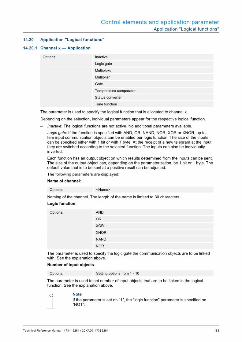
Control elements and application parameter Application "Logical functions"
Technical Reference Manual 1473-1-9264 / 2CKA001473B9264 │183
14.20 Application "Logical functions"
14.20.1 Channel x — Application
Options: Inactive
Logic gate
Multiplexer
Multiplier
Gate
Temperature comparator
Status converter
Time function
The parameter is used to specify the logical function that is allocated to channel x.
Depending on the selection, individual parameters appear for the respective logical function.
– Inactive: The logical functions are not active. No additional parameters available. – Logic gate: If the function is specified with AND, OR, NAND, NOR, XOR or XNOR, up to
tem input communication objects can be enabled per logic function. The size of the inputs can be specified either with 1 bit or with 1 byte. At the receipt of a new telegram at the input, they are switched according to the selected function. The inputs can also be individually inverted.
Each function has an output object on which results determined from the inputs can be sent. The size of the output object can, depending on the parameterization, be 1 bit or 1 byte. The default value that is to be sent at a positive result can be adjusted.
The following parameters are displayed: Name of channel:
Options: <Name>
Naming of the channel. The length of the name is limited to 30 characters. Logic function:
Options: AND
OR
XOR
XNOR
NAND
NOR
The parameter is used to specify the logic gate the communication objects are to be linked with. See the explanation above. Number of input objects:
Options: Setting options from 1 - 10
The parameter is used to set number of input objects that are to be linked in the logical function. See the explanation above.
Note If the parameter is set on "1", the "logic function" parameter is specified on "NOT".
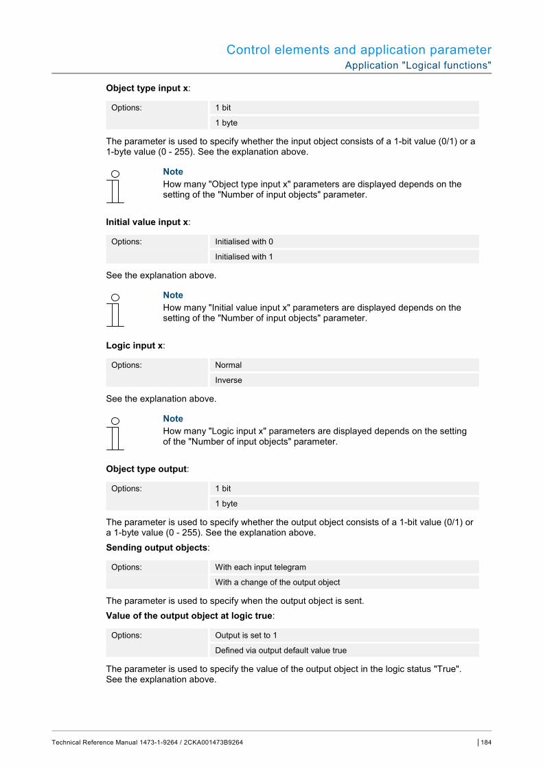
Control elements and application parameter Application "Logical functions"
Technical Reference Manual 1473-1-9264 / 2CKA001473B9264 │184
Object type input x:
Options: 1 bit
1 byte
The parameter is used to specify whether the input object consists of a 1-bit value (0/1) or a 1-byte value (0 - 255). See the explanation above.
Note How many "Object type input x" parameters are displayed depends on the setting of the "Number of input objects" parameter.
Initial value input x:
Options: Initialised with 0
Initialised with 1
See the explanation above.
Note How many "Initial value input x" parameters are displayed depends on the setting of the "Number of input objects" parameter.
Logic input x:
Options: Normal
Inverse
See the explanation above.
Note How many "Logic input x" parameters are displayed depends on the setting of the "Number of input objects" parameter.
Object type output:
Options: 1 bit
1 byte
The parameter is used to specify whether the output object consists of a 1-bit value (0/1) or a 1-byte value (0 - 255). See the explanation above. Sending output objects:
Options: With each input telegram
With a change of the output object
The parameter is used to specify when the output object is sent. Value of the output object at logic true:
Options: Output is set to 1
Defined via output default value true
The parameter is used to specify the value of the output object in the logic status "True". See the explanation above.

Control elements and application parameter Application "Logical functions"
Technical Reference Manual 1473-1-9264 / 2CKA001473B9264 │185
Value of the output object at logic untrue:
Options: Output is set to 0
Defined via output default value untrue
The parameter is used to specify the value of the output object in the logic status "Untrue". See the explanation above.
– Multiplexer: This logical function is used to steer the input data targeted to the output. The function has four communication objects "Control", "Input 1", "Input 2" and "Output". The bit-size of the inputs and outputs can also be set on 1 byte or 2 byte via the "Object type input/output" parameter. The above functionality is retained. This means that only input 1 is visible on the output when the control input has the value "1". Input 2 is switched to the output as soon as the control input has the value "0".
Note The output is only sent when there is an actual change of the inputs. If, for example, the control input changes without a change of the input values, the output signal remains as it is. A new output value is sent only when an input signal changes.
The following parameters are displayed: Name of channel:
Options: <Name>
Naming of the channel. The length of the name is limited to 60 characters. Object type input/output:
Options: 1 bit
1 byte
2 bytes
The parameter is used to specify the size of the communication object. See the explanation above.
– Multiplier: This function makes it possible to send up to ten output telegrams with one input telegram. The size of the input communication object is 1 bit or 1 byte. The size of the output communication objects can be either 1 bit or 1 byte. The size is adjusted via a corresponding parameter.
Whether a multiplier is triggered at an ON or OFF telegram or via a 1-byte value between 0 and 255, can be specified via the "Start command" setting. There is also the option of sending the output telegrams consecutively time-delayed. The default delay time is 200 ms.
The values for sending output telegrams can be set individually for each output via a corresponding parameter. "On" or "Off" can be set for 1-bit outputs. Values from 0 to 100% can be specified for 1-byte outputs.
The following parameters are displayed: Name of channel:
Options: <Name>
Naming of the channel. The length of the name is limited to 60 characters.
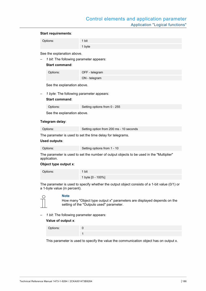
Control elements and application parameter Application "Logical functions"
Technical Reference Manual 1473-1-9264 / 2CKA001473B9264 │186
Start requirements:
Options: 1 bit
1 byte
See the explanation above. – 1 bit: The following parameter appears:
Start command:
Options: OFF - telegram
ON - telegram
See the explanation above.
– 1 byte: The following parameter appears: Start command:
Options: Setting options from 0 - 255
See the explanation above.
Telegram delay:
Options: Setting option from 200 ms - 10 seconds
The parameter is used to set the time delay for telegrams. Used outputs:
Options: Setting options from 1 - 10
The parameter is used to set the number of output objects to be used in the "Multiplier" application. Object type output x:
Options: 1 bit
1 byte [0 - 100%]
The parameter is used to specify whether the output object consists of a 1-bit value (0/1) or a 1-byte value (in percent).
Note How many "Object type output x" parameters are displayed depends on the setting of the "Outputs used" parameter.
– 1 bit: The following parameter appears: Value of output x:
Options: 0
1
This parameter is used to specify the value the communication object has on output x.

Control elements and application parameter Application "Logical functions"
Technical Reference Manual 1473-1-9264 / 2CKA001473B9264 │187
– 1 byte [0 - 100%]: The following parameter appears: Value of output x:
Options: Setting options from 0 - 100
This parameter is used to specify the value (in percent) the communication object has on output x.
Note How many "Value of output x" parameters are displayed depends on the setting of the "Outputs used" parameter.
– Gate: This logical function can be used to filter certain signals and block the flow of signals temporarily. The function has three communication objects "Control input", "Input" and "Output". The contol input or output can take on size 1 bit, 2 bit, 1 byte, 2 byte, 4 byte or 14 byte. The control can take place from input to output, from output to input and in both directions. Enabling via the control input can take place via an ON or OFF telegram.
It can also be set as to whether the input signals are to be stored or not "during the blocking phase". If the setting "Store input signals during blocking" has been selected and if a telegram has been received on the input during the blocking phase, the output sends its value.
If the size of the input and output objects is 1 bit, the input can also be inverted. This allows an inverting member to be implemented via a gate. It is also possible to block signals via the "Filter function" setting. Either "Do not filter" or the signal "Filtered out ON" or the signal "Filtered out OFF" is sent.
The following parameters are displayed: Name of channel:
Options: <Name>
Naming of the channel. The length of the name is limited to 60 characters. Direction of data flow:
Options: Input -> Output
Output -> Input
Input <-> Output
The parameter is used to specify the direction data are sent via the channel. See the explanation above. Sending an output telegram:
Options: At every receipt
At changed values
The parameter is used to specify when the output telegram is sent. Control input:
Options: Activation at OFF
Activation at ON
See the explanation above.
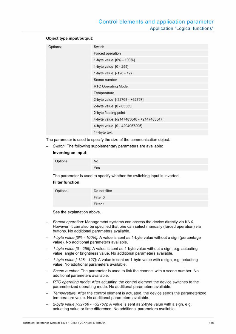
Control elements and application parameter Application "Logical functions"
Technical Reference Manual 1473-1-9264 / 2CKA001473B9264 │188
Object type input/output:
Options: Switch
Forced operation
1-byte value [0% - 100%]
1-byte value [0 - 255]
1-byte value [-128 - 127]
Scene number
RTC Operating Mode
Temperature
2-byte value [-32768 - +32767]
2-byte value [0 - 65535]
2-byte floating point
4-byte value [-2147483648 - +2147483647]
4-byte value [0 - 4294967295]
14-byte text
The parameter is used to specify the size of the communication object. – Switch: The following supplementary parameters are available:
Inverting an input:
Options: No
Yes
The parameter is used to specify whether the switching input is inverted. Filter function:
Options: Do not filter
Filter 0
Filter 1
See the explanation above.
– Forced operation: Management systems can access the device directly via KNX. However, it can also be specified that one can select manually (forced operation) via buttons. No additional parameters available.
– 1-byte value [0% - 100%]: A value is sent as 1-byte value without a sign (percentage value). No additional parameters available.
– 1-byte value [0 - 255]: A value is sent as 1-byte value without a sign, e.g. actuating value, angle or brightness value. No additional parameters available.
– 1-byte value [-128 - 127]: A value is sent as 1-byte value with a sign, e.g. actuating value. No additional parameters available.
– Scene number: The parameter is used to link the channel with a scene number. No additional parameters available.
– RTC operating mode: After actuating the control element the device switches to the parameterized operating mode. No additional parameters available.
– Temperature: After the control element is actuated, the device sends the parameterized temperature value. No additional parameters available.
– 2-byte value [-32768 - +32767]: A value is sent as 2-byte value with a sign, e.g. actuating value or time difference. No additional parameters available.
Control elements and application parameter Application "Logical functions"
Technical Reference Manual 1473-1-9264 / 2CKA001473B9264 │189
– 2-byte value [0 - 65535]: A value is sent as 2-byte value without a sign, e.g. actuating value or time interval. No additional parameters available.
– 2-byte floating point: A value is sent as 2-byte floating point value, e.g. a temperature value, a time duration, a performance or a consumption value. No additional parameters available.
– 4-byte value [-2147483648 - 2147483647]: A value is sent as 4-byte value with a sign, e.g. actuating value or time difference. No additional parameters available.
– 4-byte value [0 - 4294967295]: A value is sent as 4-byte value without a sign, e.g. actuating value. No additional parameters available.
– 14-byte text: Makes it possible to send a text. No additional parameters available. Saving input signal during blocking:
Options: No
Yes
See the explanation above.
– Temperature comparator: This function can be used to compare temperature values. The following parameters are displayed: Name of channel:
Options: <Name>
Naming of the channel. The length of the name is limited to 60 characters. Type of comparator:
Options: Temperature with a constant
2 Temperatures
This function can be used to compare two temperatures. Or a temperature can be compared with an internal specified temperature value (constant). – Temperature with a constant: This function makes an input available with a 2-byte
communication object. On this object temperature telegrams are received and compared, which are sent from a KNX temperature sensor for example.
The following parameters are displayed: Input 2 [°C]:
Options: Setting options from -30 - +70
This parameter is used to specify the value with which the temperature at input 1 is to be compared. Hysteresis:
Options: Setting options from 0.5 - 10
– 2 temperatures: This function makes two separate inputs with 2-byte communication objects available. On these objects temperature telegrams are received and compared with each other, which are sent from KNX temperature sensors. No additional parameters available.
Control elements and application parameter Application "Logical functions"
Technical Reference Manual 1473-1-9264 / 2CKA001473B9264 │190
Object type of the output:
Options: 1 bit
1 byte
The parameter is used to specify whether the output object sends a 1-bit value (0/1) or a 1-byte value (0 - 255). – 1 bit: The following supplementary parameters are available:
Sending value when input 1 > input 2:
Options: OFF telegram
ON telegram
The parameter is used to specify which output object is sent (ON or OFF) when input 1 is logically larger than input 2. Sending value when input 1 < input 2:
Options: OFF telegram
ON telegram
The parameter is used to specify which output object is sent (ON or OFF) when input 1 is logically smaller than input 2.
– 1 byte: The following supplementary parameters are available: Sending value when input 1 > input 2:
Options: Setting options from 0 - 255
The parameter is used to specify which output object is sent when input 1 is logically larger than input 2. Sending value when input 1 < input 2:
Options: Setting options from 0 - 255
The parameter is used to specify which output object is sent when input 1 is logically smaller than input 2.
Telegram is sent by:
Options: Change output
Output 1 is larger than input 2
Output 1 is smaller than input 2
A telegram is sent when the selected condition is met. Cyclic sending of output:
Options: No
Yes
The parameter is used to specify whether the output telegram is sent in cycles. – No: No additional parameters available. – Yes: The following parameter appears:
Control elements and application parameter Application "Logical functions"
Technical Reference Manual 1473-1-9264 / 2CKA001473B9264 │191
Cycle time:
Options: Setting options from 00:00:01 - 00:30:00
The parameter is used to specify the cycle time (hh:mm:ss).
– Status converter: This function is used to convert an input value into a 14-byte text or divide it into several 1-bit telegrams. The following parameters are displayed: Name of channel:
Options: <Name>
Naming of the channel. The length of the name is limited to 60 characters. Type of converter:
Options: 1 bit -> text
1 byte -> text
1 byte -> 8x1 bit
2 byte -> 16x1 bit
See the explanation above. – 1 bit -> text: A 1-bit value is converted into text. The following parameter appears:
Number of inputs:
Options: Setting options from 1 - 4
The parameter is used to set the number of available inputs. The following parameter appears: Using value xxxx:
Options: No
Yes
The parameter is used to specify whether the signal is used for the conversion into text. – No: No additional parameters available. – Yes: The following parameter appears: Text for value xxxx:
Options: <text>
Naming of the value. The length of the text is limited to 15 characters.
Note How many "Use value xxxxx" parameters and "Text for value xxxx" are displayed depends on the setting of the "Number of inputs" parameter.
– 1 byte -> text: A 1-byte value is converted into text. The following parameter appears: Number of texts:
Options: Setting options from 1 - 16
The parameter is used to set the number of values to be converted into text. The following parameters are displayed:
Control elements and application parameter Application "Logical functions"
Technical Reference Manual 1473-1-9264 / 2CKA001473B9264 │192
Text x for value [0 - 255]:
Options: Setting options from 0 - 255
The parameter is used to set which value is to be converted into text x. Text x:
Options: <text>
Naming of the value. The length of the text is limited to 15 characters.
– 1 byte -> 8x1 bit: A 1-byte value is converted into eight 1-bit values. The following parameter appears: Sending output values:
Options: At every receipt
At changed values
The parameter is used to specify when the 1-byte value is converted and sent.
– 2 byte -> 16x1 bit: A 1-byte value is converted into sixteen 1-bit values. The following parameter appears: Sending output values:
Options: At every receipt
At changed values
The parameter is used to specify when the 1-byte value is converted and sent.
– Time function: The 1-bit communication objects "Input" and "Output" are available for the time function.
When an ON telegram is received via 1-bit communication object "Input", the staircase light period is triggered and an ON telegram is sent on 1-bit communication object "Output". After the set period has expired, an OFF telegram is sent via the output object.
When an OFF telegram is received during the staircase light period, the staircase light period is reset and an OFF telegram is sent on the output.
When an ON telegram is received again during the staircase light period, the delay time can be restarted again (retrigger). When this behaviour is desired, the "Retrigger" parameter is to be set on "Yes". A switch-on delay time can be additionally activated. This means that the start of the staircase light period and the sending of an ON telegram on the output object can happen only after the switch-on delay time has expired.
The following parameters are displayed: Name of channel:
Options: <Name>
Naming of the channel. The length of the name is limited to 60 characters. Type of time function:
Options: Staircase lighting
ON/OFF delay
The parameter is used to select between a staicase light function and an On/Off delay. – Staircase lighting: The following parameters are displayed:
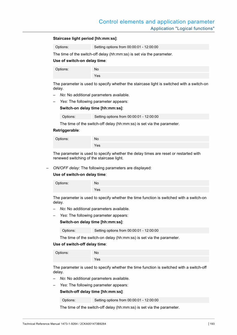
Control elements and application parameter Application "Logical functions"
Technical Reference Manual 1473-1-9264 / 2CKA001473B9264 │193
Staircase light period [hh:mm:ss]:
Options: Setting options from 00:00:01 - 12:00:00
The time of the switch-off delay (hh:mm:ss) is set via the parameter. Use of switch-on delay time:
Options: No
Yes
The parameter is used to specify whether the staircase light is switched with a switch-on delay. – No: No additional parameters available. – Yes: The following parameter appears: Switch-on delay time [hh:mm:ss]:
Options: Setting options from 00:00:01 - 12:00:00
The time of the switch-off delay (hh:mm:ss) is set via the parameter. Retriggerable:
Options: No
Yes
The parameter is used to specify whether the delay times are reset or restarted with renewed switching of the staircase light.
– ON/OFF delay: The following parameters are displayed: Use of switch-on delay time:
Options: No
Yes
The parameter is used to specify whether the time function is switched with a switch-on delay. – No: No additional parameters available. – Yes: The following parameter appears: Switch-on delay time [hh:mm:ss]:
Options: Setting options from 00:00:01 - 12:00:00
The time of the switch-on delay (hh:mm:ss) is set via the parameter. Use of switch-off delay time:
Options: No
Yes
The parameter is used to specify whether the time function is switched with a switch-off delay. – No: No additional parameters available. – Yes: The following parameter appears: Switch-off delay time [hh:mm:ss]:
Options: Setting options from 00:00:01 - 12:00:00
The time of the switch-off delay (hh:mm:ss) is set via the parameter.

Control elements and application parameter Application "Internal RTC"
Technical Reference Manual 1473-1-9264 / 2CKA001473B9264 │194
14.21 Application "Internal RTC"
14.21.1 General - Device function
Options: Single device
Master device
Temperature transmitter
– Single device: The device is used individually in a room for temperature control with fixed temperature values.
– Master device: There are at least two temperature controllers in a room. One device is to be programmed as master device and additional ones as slave devices/temperature sensors. The master device is to be linked with the slave devices via the correspondingly marked communication objects. The master device performs the temperature control.
– Temperature transmitter (slave device): The device only sends the measured temperature to the KNX bus.
14.21.2 General - Control function
Options: Heating
Heating with additional stage
Cooling
Cooling with additional stage
Heating and cooling
Heating and cooling with additional stage
– Heating: For operating a heat-based automatic single-room control. The temperature is regulated to the setpoint value defined in the parameter. The "Controller type" and "Heating type" can be programmed for optimal control.
– Heating with additional stage: In addition to the control function described under heating, the additional stage enables the activation of an additional heating circuit. This type of additional stage is used, for example, to quickly heat up a bathroom with floor heating via a heated towel rack.
– Cooling: For operating a cooling-based automatic single-room control. The temperature is regulated to the setpoint value defined in the parameter. The "Controller type" and "Cooling type" can be programmed for optimal control.
– Cooling with additional stage: In addition to the control function described under cooling, the additional stage enables the activation of an additional cooling device. This type of additional stage is used, for example, to quickly cool a room via an added cooling device.

Control elements and application parameter Application "Internal RTC"
Technical Reference Manual 1473-1-9264 / 2CKA001473B9264 │195
– Heating and cooling: For operating a two-wire or four-wire system used to heat or cool a room. Switching between heating and cooling takes place using a central switch (two-wire system) or is carried out manually and / or automatically via the single room temperature controller (four-wire system).
– Heating and cooling with an additional stage: In addition to the heating and cooling functions, one additional stage each with an autonomous controller type can be programmed.
Note This parameter is only available if the "Device function" parameter is set on "Single device" or "Master device".
14.21.3 General - Operating mode after reset
Options: Comfort
Standby
Eco mode
Cooling with additional stage
Frost/heat protection
After a reset the device will run in the operating mode after a restart until a new operating mode is set as the result of device operation or by communication objects, as the case may be. This operating mode should be defined during the planning phase. An improperly defined operating mode can result in a loss of comfort or increased energy consumption.
– Comfort: If the room temperature is not automatically lowered and the room is therefore controlled independent of its use.
– Standby: If the room is controlled automatically, e.g. by a presence detector, as a function of its use.
– Eco mode: If the room is controlled automatically or manually as a function of it use. – Frost/heat protection: If only the building protection function is necessary in the room after a
reset.
Note This parameter is only available if the "Device function" parameter is set on "Single device" or "Master device".
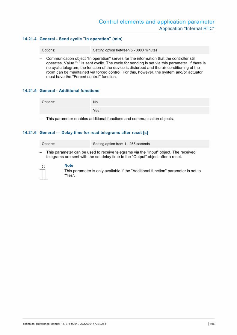
Control elements and application parameter Application "Internal RTC"
Technical Reference Manual 1473-1-9264 / 2CKA001473B9264 │196
14.21.4 General - Send cyclic "In operation" (min)
Options: Setting option between 5 - 3000 minutes
– Communication object "In operation" serves for the information that the controller still operates. Value "1" is sent cyclic. The cycle for sending is set via this parameter. If there is no cyclic telegram, the function of the device is disturbed and the air-conditioning of the room can be maintained via forced control. For this, however, the system and/or actuator must have the "Forced control" function.
14.21.5 General - Additional functions
Options: No
Yes
– This parameter enables additional functions and communication objects.
14.21.6 General — Delay time for read telegrams after reset [s]
Options: Setting option from 1 - 255 seconds
– This parameter can be used to receive telegrams via the "Input" object. The received telegrams are sent with the set delay time to the "Output" object after a reset.
Note This parameter is only available if the "Additional function" parameter is set to "Yes".
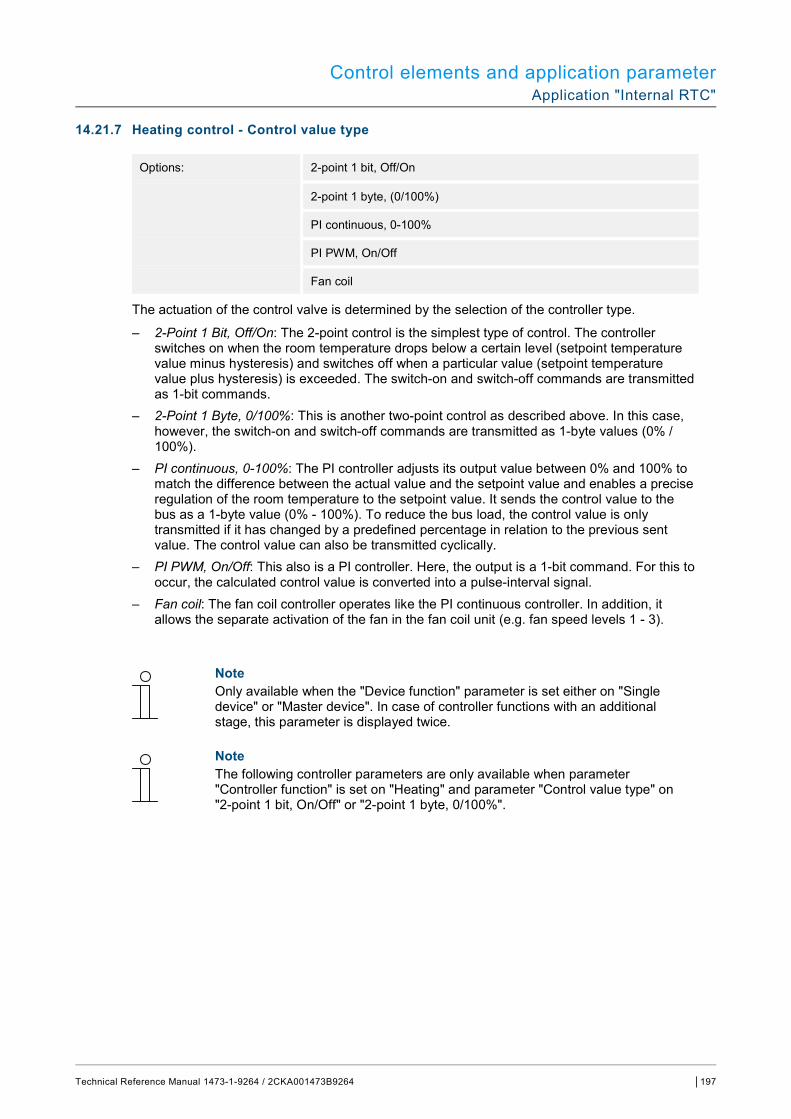
Control elements and application parameter Application "Internal RTC"
Technical Reference Manual 1473-1-9264 / 2CKA001473B9264 │197
14.21.7 Heating control - Control value type
Options: 2-point 1 bit, Off/On
2-point 1 byte, (0/100%)
PI continuous, 0-100%
PI PWM, On/Off
Fan coil
The actuation of the control valve is determined by the selection of the controller type.
– 2-Point 1 Bit, Off/On: The 2-point control is the simplest type of control. The controller switches on when the room temperature drops below a certain level (setpoint temperature value minus hysteresis) and switches off when a particular value (setpoint temperature value plus hysteresis) is exceeded. The switch-on and switch-off commands are transmitted as 1-bit commands.
– 2-Point 1 Byte, 0/100%: This is another two-point control as described above. In this case, however, the switch-on and switch-off commands are transmitted as 1-byte values (0% / 100%).
– PI continuous, 0-100%: The PI controller adjusts its output value between 0% and 100% to match the difference between the actual value and the setpoint value and enables a precise regulation of the room temperature to the setpoint value. It sends the control value to the bus as a 1-byte value (0% - 100%). To reduce the bus load, the control value is only transmitted if it has changed by a predefined percentage in relation to the previous sent value. The control value can also be transmitted cyclically.
– PI PWM, On/Off: This also is a PI controller. Here, the output is a 1-bit command. For this to occur, the calculated control value is converted into a pulse-interval signal.
– Fan coil: The fan coil controller operates like the PI continuous controller. In addition, it allows the separate activation of the fan in the fan coil unit (e.g. fan speed levels 1 - 3).
Note Only available when the "Device function" parameter is set either on "Single device" or "Master device". In case of controller functions with an additional stage, this parameter is displayed twice.
Note The following controller parameters are only available when parameter "Controller function" is set on "Heating" and parameter "Control value type" on "2-point 1 bit, On/Off" or "2-point 1 byte, 0/100%".
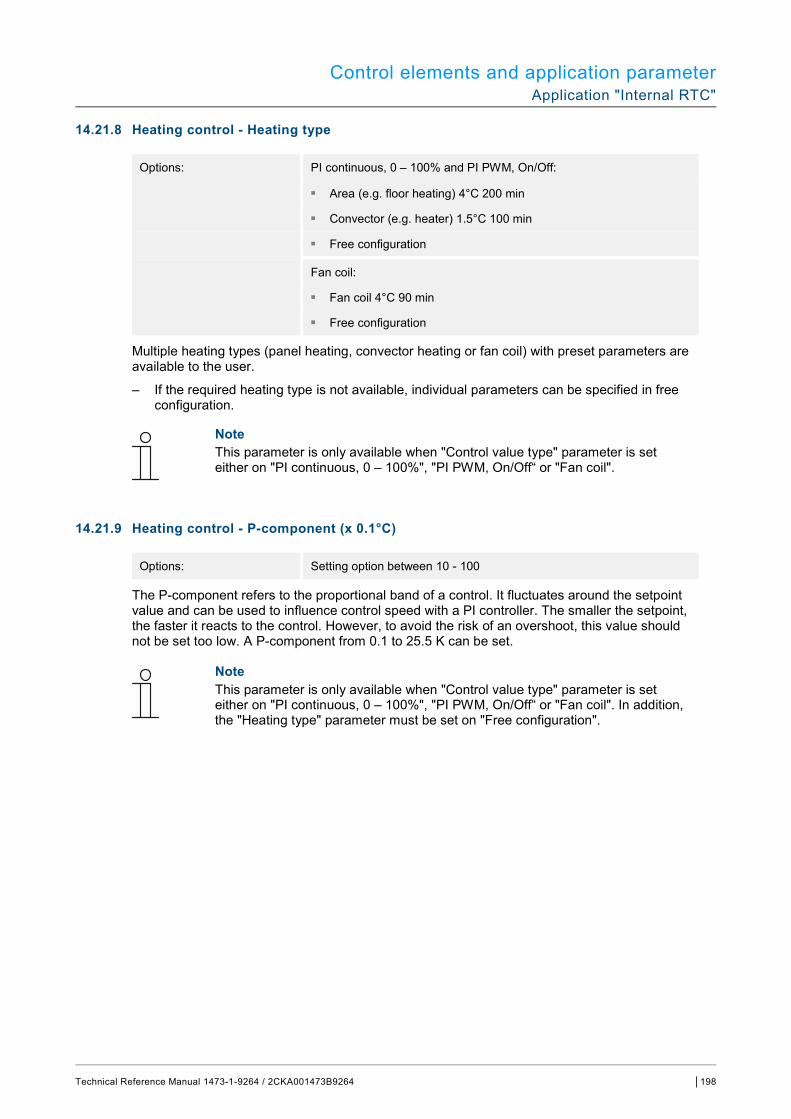
Control elements and application parameter Application "Internal RTC"
Technical Reference Manual 1473-1-9264 / 2CKA001473B9264 │198
14.21.8 Heating control - Heating type
Options: PI continuous, 0 – 100% and PI PWM, On/Off:
■ Area (e.g. floor heating) 4°C 200 min
■ Convector (e.g. heater) 1.5°C 100 min
■ Free configuration
Fan coil:
■ Fan coil 4°C 90 min
■ Free configuration
Multiple heating types (panel heating, convector heating or fan coil) with preset parameters are available to the user.
– If the required heating type is not available, individual parameters can be specified in free configuration.
Note This parameter is only available when "Control value type" parameter is set either on "PI continuous, 0 – 100%", "PI PWM, On/Off“ or "Fan coil".
14.21.9 Heating control - P-component (x 0.1°C)
Options: Setting option between 10 - 100
The P-component refers to the proportional band of a control. It fluctuates around the setpoint value and can be used to influence control speed with a PI controller. The smaller the setpoint, the faster it reacts to the control. However, to avoid the risk of an overshoot, this value should not be set too low. A P-component from 0.1 to 25.5 K can be set.
Note This parameter is only available when "Control value type" parameter is set either on "PI continuous, 0 – 100%", "PI PWM, On/Off“ or "Fan coil". In addition, the "Heating type" parameter must be set on "Free configuration".

Control elements and application parameter Application "Internal RTC"
Technical Reference Manual 1473-1-9264 / 2CKA001473B9264 │199
14.21.10 Heating control - I-component (min.)
Options: Setting option between 0 - 255
The I-component refers to the reset time of a control. The integral component has the effect of moving the room temperature slowly toward, and ultimately reaching, the setpoint value. Depending on the type of system used, the reset time has to have different values. In general, the more inactive the overall system, the greater the reset time.
Note This parameter is only available when "Control value type" parameter is set either on "PI continuous, 0 – 100%", "PI PWM, On/Off“ or "Fan coil". In addition, the "Heating type" parameter must be set on "Free configuration".
14.21.11 Heating control — Extended settings
Options: No
Yes
– This parameter enables additional functions, e.g. "Status object heating".
14.21.12 Basic stage heating
Note Only available when the "Extended settings" parameter under "Heating control" is set on "Yes".
14.21.13 Basic stage heating - Status object heating
Options: No
Yes
– This parameter enables the "Status heating" communication object.
14.21.14 Basic stage heating - Mode of the control value
Options: Normal
Inverse
The mode of the control value can be used to adapt the control value to de-energised opened (normal) or de-energised closed (inverse) valves.
– Normal: Value 0 means "Valve closed". – Inverse: Value 0 means "Valve open".
Control elements and application parameter Application "Internal RTC"
Technical Reference Manual 1473-1-9264 / 2CKA001473B9264 │200
14.21.15 Basic stage heating - Hysteresis (x 0.1°C)
Options: Setting option between 3 - 255
The hysteresis of the two-point controller specifies the fluctuation range of the controller around the setpoint value. The lower switching point is located at "Setpoint value minus hysteresis" and the upper point is at "Setpoint value plus hysteresis".
Note This parameter is only available when the "Control value type" parameter is set either on "2-point 1 Bit, Off/On" or "2-point 1 Byte, 0/100%".
14.21.16 Basic stage heating - Control value difference for sending of heating control value
Options: 2 %
5 %
10 %
Send cyclic only
The control values of the 0 - 100% PI continuous controller are not transmitted after every calculation. Instead, they are transmitted when the calculation results in a value that is different enough to the previous sent value to make a transmission meaningful. This value difference can be entered here.
Note This parameter is only available when "Control value type" parameter is set either on "PI continuous, 0 – 100%", "PI PWM, On/Off“ or "Fan coil".
14.21.17 Basic stage heating - Cyclic sending of the control value (min)
Options: Setting option between 1 - 60 minutes
The current control value used by the device can be cyclically transmitted to the bus.
Note This parameter is only available when the "Control value type" parameter is set either on "2-point 1 Bit, Off/On", "2-point 1 Byte, 0/100%", "PI continuous, 0-100%" or "Fan coil".
Control elements and application parameter Application "Internal RTC"
Technical Reference Manual 1473-1-9264 / 2CKA001473B9264 │201
14.21.18 Basic stage heating - PWM cycle heating (min)
Options: Setting option between 1 - 60 minutes
In PI PWM, On/off the control value percentage values are converted into a pulse-interval signal. This means that a selected PWM cycle will be divided into an on-phase and an off-phase based on the control value. Accordingly, a control value output of 33% in a PWM cycle of 15 min. results in an "On-phase" of five minutes and an "Off-phase" of 10 min. The time for a PWM cycle can be specified here.
Note This parameter is only available when the "Control value type" parameter is set on "PI PWM, On/Off“.
14.21.19 Basic stage heating - Maximum control value (0 - 255)
Options: Setting option between 0 - 255
The maximum control value of the PI controller defines the maximum value outputted by the controller. If a maximum value under 255 is chosen, the value will not be exceeded, even if the controller calculates a higher control value.
Note This parameter is only available when "Control value type" parameter is set either on "PI continuous, 0 – 100%", "PI PWM, On/Off“ or "Fan coil".
14.21.20 Basic stage heating - Minimum control value for basic load (0 to 255)
Options: Setting option between 0 - 255
The minimum control value of the PI controller defines the minimum value output by the controller. If a minimum value greater than zero is chosen, the controller will not output a lower value, even if it calculates a value that is lower. This parameter can be used to set a basic load, e.g. for operating floor heating. Even if the controller calculates the control value zero, a heating medium will flow through the floor heating system to prevent the floor from cooling down. Under "Settings of basic load", it is also possible to define whether this basic load will be permanently active or whether it will be switched by the "Basic load" object.
Note This parameter is only available when "Control value type" parameter is set either on "PI continuous, 0 – 100%", "PI PWM, On/Off“ or "Fan coil".

Control elements and application parameter Application "Internal RTC"
Technical Reference Manual 1473-1-9264 / 2CKA001473B9264 │202
14.21.21 Settings of basic load - Minimum control value for basic load > 0
Options: Always active
Activate via object
The function finds application when in the desired area, e.g. with floor heating, the floor is to have a basic warmth. The size of the minimum control value specifies the volume of heating medium that flows through the controlled area, even when the calculation of the control value of the controller would indicate a lower value.
– Always active: Here it is possible to define whether this basic load will be permanently active or whether it will be switched via the "Basic load" object.
– Activate via object: When this parameter is selected, the basic load function, which means the minimum control value with a value higher than zero, can be activated (1) or deactivated (2). If it is activated, then the heating medium will always be fed through the system with at least the minimum control value. If it is deactivated, the control value can be reduced to zero with the controller.
Note This parameter is only available when the "Control value type" parameter is set either on "2-point 1 bit, On/Off", "2-point 1 byte, 0/100%", "PI continuous, 0-100%" or "Fan coil".
14.21.22 Basic load settings — Basic load active when controller is off
Options: No
Yes
– This parameter switches the basic load active when the controller is off.
Note This parameter is only available when "Control value type" parameter is set either on "PI continuous, 0 – 100%", "PI PWM, On/Off“ or "Fan coil".
Control elements and application parameter Application "Internal RTC"
Technical Reference Manual 1473-1-9264 / 2CKA001473B9264 │203
Note The following parameters are available without enabling "Extended settings".
14.21.23 Setpoint settings - Setpoint temperature for heating comfort (°C)
Options: Setting option between 10 - 40
Specifies the comfort temperature for heating when people are present.
Note This parameter is only available when the "Control function" parameter is set on "Heating" or "Heating with additional stage".
14.21.24 Setpoint settings - Reduction for standby heating (°C)
Options: Setting option between 10 - 40
Specifies the temperature in heating mode when nobody is present. On devices with a display, this mode is indicated by the standby icon.
Note This parameter is only available when the "Control function" parameter is set on "Heating", "Heating with additional stage", "Heating and cooling" or "Heating and cooling with additional stages".
14.21.25 Setpoint settings - Reduction for ECO heating (°C)
Options: Setting option between 0 - 15
Specifies the temperature in heating mode when nobody is present. On devices with a display, this mode is indicated by the eco icon.
Control elements and application parameter Application "Internal RTC"
Technical Reference Manual 1473-1-9264 / 2CKA001473B9264 │204
14.21.26 Setpoint settings - Set-point temperature for frost protection (°C)
Options: Setting option between 5 - 15
Function for protecting the building against the cold. On devices with a display, this mode is indicated by the frost protection icon. Manual operation is blocked.
Note This parameter is only available when the "Control function" parameter is set on "Heating", "Heating with additional stage", "Heating and cooling" or "Heating and cooling with additional stages".
14.21.27 Setpoint settings - Send current setpoint
Options: Cyclic and during change
Only for change
The current setpoint value can be sent to the bus either cyclically and after a change, or only after a change.
14.21.28 Setpoint settings - Cyclic sending of the current set-point temperature (min)
Options: Setting option between 5 - 240
This parameter is used to specify the amount of time that will elapse before the current setpoint value is automatically transmitted.
Note This parameter is only available when the "Send current setpoint" is set on "Only during change".
14.21.29 Setpoint adjustment — Maximum manual increase during heating mode (0 - 9°C)
Options: Setting option between 0 - 9
This preset can be used to limit the manual increase during heating.
Note This parameter is only available when parameter "Controller function" is set on "Heating" and parameter "Control value type" on "2-point 1 bit, On/Off" or "2-point 1 byte, 0/100%".
Control elements and application parameter Application "Internal RTC"
Technical Reference Manual 1473-1-9264 / 2CKA001473B9264 │205
14.21.30 Setpoint adjustment — Maximum manual reduction during heating mode (0 - 9°C)
Options: Setting option between 0 - 9
This preset can be used to limit the manual decrease during heating.
Note This parameter is only available when parameter "Controller function" is set on "Heating" and parameter "Control value type" on "2-point 1 bit, On/Off" or "2-point 1 byte, 0/100%".
14.21.31 Setpoint adjustment - Resetting of the manual adjustment for receipt of a basic setpoint
Options: No
Yes
Activating this parameter will cause the manual adjustment to be deleted and the new setpoint value to be provided when a new value is received via the "Basic setpoint" object.
If the parameter is deactivated, the manual adjustment is added to the new base setpoint value. Example: Previous base setpoint value of 21°C + manual adjustment of 1.5°C = 22.5°C. The object receives a new basic setpoint of 18°C plus the previous manual adjustment of 1.5°C for a total of 19.5°C.
14.21.32 Setpoint adjustment - Resetting the manual adjustment for change of operating mode
Options: No
Yes
If the device switches to a new operating mode, the manual adjustment is deleted and the parameterized setpoint temperature for the operating mode plus any change by the base setpoint value object will be applied if this parameter is activated. Example: Comfort temperature of 21°C plus manual adjustment of 1.5°C = 22.5°C. Change to Eco with programmed temperature 17°C. The device regulates the temperature to 17°C, since the manual adjustment is deleted.
If the parameter is deactivated, the manual setpoint adjustment will be added to the temperature in the new operating mode. Example: Comfort temperature of 21°C plus manual adjustment of 1.5°C = 22.5°C. If the system switches to Eco with a parameterized temperature of 17°C, the device regulates the temperature to 18.5°C, since the manual adjustment is added.

Control elements and application parameter Application "Internal RTC"
Technical Reference Manual 1473-1-9264 / 2CKA001473B9264 │206
14.21.33 Setpoint adjustment - Resetting the manual adjustment via object
Options: No
Yes
If this parameter is activated, a separate object can be used to delete the manual adjustment at any time. Example of application: Resetting the manual adjustment on all devices located in a building using a system clock.
14.21.34 Setpoint adjustment - Permanent storage of on-site operation
Options: No
Yes
If this parameter is activated, the manual settings for setpoint and, where applicable, fan speed level, as well as the value of the "Basic load" object, will be stored in the device and re-activated after a reset. The same applies to the operating mode.
If the device is re-programmed, the stored setpoint values will also be deleted.
14.21.35 Temperature reading - Inputs of temperature reading
Options: Internal measurement
External measurement
Weighted measurement
The room temperature can be measured at the device or fed to the device by an object via the bus. In addition, weighted measuring is also available, in which the weighted average of up to three temperature values (1 x internal, 2 x external) is calculated and used as an input value for control.
14.21.36 Temperature reading - Inputs of weighted temperature reading
Options: Internal and external measurement
2 x external measurement
Internal and 2x external measurement
Specifies the temperature reading inputs for the weighted measurement, in which the calculated weighted average of the inputs is used as an input value for control
Note This parameter is only available when the "Inputs of temperature reading" parameter is set on "Weighted measurement".
Control elements and application parameter Application "Internal RTC"
Technical Reference Manual 1473-1-9264 / 2CKA001473B9264 │207
14.21.37 Temperature reading — Weighting of internal measurement (0 to 100%)
Options: Setting option between 0 - 100
Specifying the weighting of the internal measurement from 0 to 100%.
Note This parameter is only available when the "Inputs of weighted temperature reading" parameter is set on "Internal and external measurement" or "Internal and 2x external measurement".
14.21.38 Temperature reading — Weighting of external measurement (0 to 100%)
Options: Setting option between 0 - 100
Specifying the weighting of the external measurement from 0 to 100%.
Note This parameter is only available when the "Inputs of weighted temperature reading" parameter is set on "Internal and external measurement", "2x external measurement" or "Internal and 2x external measurement".
14.21.39 Temperature reading — Weighting of external measurement 2 (0 to 100%)
Options: Setting option between 0 - 100
Specifying the weighting of the external measurement 2 from 0 to 100%. The setting together with the weighting of the external measurement (0 - 100%) must result in 100%.
Note This parameter is only available when the "Inputs of weighted temperature reading" parameter is set on "2x external measurement" or "Internal and 2x external measurement".
14.21.40 Temperature reading - Cyclic sending of the actual temperature (min)
Options: Setting option between 5 - 240
The current actual temperature used by the device can be cyclically transmitted to the bus.
Control elements and application parameter Application "Internal RTC"
Technical Reference Manual 1473-1-9264 / 2CKA001473B9264 │208
14.21.41 Temperature reading — Difference of value for sending the actual temperature (x 0.1°C)
Options: Setting option between 1 - 100
If the change in temperature exceeds the parameterised difference between the measured actual temperature and the previous actual temperature that was sent, the changed value will be transmitted.
Note This parameter is only available when the "Inputs of temperature reading" parameter is set on "Internal measurement" or "Weighted measurement".
14.21.42 Temperature reading - Adjustment value for internal temperature measurement (x 0.1°C)
Options: Setting option between 1 - 100
Every installation location has different physical conditions (interior or exterior wall, lightweight or solid wall, etc.). In order to use the actual temperature at the installation location as a measured value for the device, a temperature measurement must be performed by an external equalised and / or calibrated thermometer at the installation location. The difference between the actual temperature displayed on the device and the actual temperature determined by the external measurement device must be entered in the parameter field as an "Adjustment value".
Note ■ The calibration measurement should not be carried out immediately after the
device has been installed. The device should first adjust to the ambient temperature before calibration is carried out. The calibration measurement should be repeated shortly before or after the room is occupied.
■ This parameter is only available when the "Inputs of temperature reading" parameter is set on "Internal measurement" or "Weighted measurement".
14.21.43 Temperature reading - Monitoring time for temperature reading (0 = no monitoring) (min)
Options: Setting option between 0 - 120
If no temperature is read within the parameterized time period, the device switches to error mode. It transmits a telegram to the bus via the "Actual temperature error" object and applies the operating mode and control value for error (0 - 255) settings.
14.21.44 Temperature reading - Control value for fault (0 - 255)
Options: Setting option between 0 - 255
In the event of a failure of the actual temperature measurement, the device will no longer be able to independently determine the control value. In case of an error, a PWM control (1 Bit) with a fixed cycle time of 15 minutes is used automatically instead of a parameterized 2-point control (1 Bit). In this case the set parameter value is taken into consideration for the control value during an error.

Control elements and application parameter Application "Internal RTC"
Technical Reference Manual 1473-1-9264 / 2CKA001473B9264 │209
14.21.45 Alarm functions - Frost alarm temperature for HVAC and RHCC status (°C)
Options: Setting option between 0 - 15
The RHCC status and HVAC objects have a frost alarm bit. It the input temperature of the controller drops below the temperature set in this parameter, then the frost alarm bit is set in the status objects. It is reset when the temperature is exceeded.
14.21.46 Alarm functions - Heat alarm temperature for RHCC status (°C)
Options: Setting option between 25 - 70
The RHCC status object has a heat alarm bit. If the input temperature of the controller exceeds the temperature set in this parameter, then the heat alarm bit is set in the status object. It is reset when the temperature falls below the set temperature.
Note The following parameters are available when the "Controller function" parameter is set on "Heating with additional stage". The same parameters are available which are also available when parameter "Controller function" is set on "Heating" and parameter "Control value type" on "2-point 1 bit, On/Off" or "2-point 1 byte, 0/100%".
Note The additional parameter "Control value type" is available for the additional stage.
14.21.47 Control of additional heating stage - Temperature difference to basic stage (x 0.1°C)
Options: Setting option between 0 - 255
The setpoint temperature of the additional stage is defined as a function of the current setpoint temperature of the base stage and is expressed as a difference. The value represents the setpoint value starting at which the additional stage will operate.
Control elements and application parameter Application "Internal RTC"
Technical Reference Manual 1473-1-9264 / 2CKA001473B9264 │210
14.21.48 Control of additional heating stage - Additional heating type
Options: PI continuous, 0 – 100% and PI PWM, On/Off:
■ Area (e.g. floor heating) 4°C 200 min
■ Convector (e.g. heater) 1.5°C 100 min
■ Free configuration
Fan coil:
■ Fan coil 4°C 90 min
■ Free configuration
Multiple heating types (panel heating, convector heating or fan coil) with preset parameters are available to the user.
– If the required heating type is not available, individual parameters can be specified in the free configuration.
Note This parameter is only available when "Control value type" parameter for the additional stage is set either on "PI continuous, 0 – 100%", "PI PWM, On/Off“ or "Fan coil".
14.21.49 Control of additional heating stage - P-component (x 0.1°C)
Options: Setting option between 10 - 100
The P-component refers to the proportional range of a control. It fluctuates around the setpoint value and can be used to influence control speed of a controller. The smaller the setpoint, the faster the controller responds. However, to avoid the risk of an overshoot, this value should not be set too low. A P-component from 0.1 to 25.5 K can be set.
Note This parameter is only available when "Control value type" parameter for the additional stage is set either on "PI continuous, 0 – 100%", "PI PWM, On/Off“ or "Fan coil". The "Additional heating type" parameter must be set on "Free configuration".
Control elements and application parameter Application "Internal RTC"
Technical Reference Manual 1473-1-9264 / 2CKA001473B9264 │211
14.21.50 Control of additional heating stage - I-component (min)
Options: Setting option between 0 - 255
The I-component refers to the reset time of a control. The integral component has the effect of moving the room temperature slowly toward, and ultimately reaching, the setpoint value. Depending on the type of system used, the reset time has to have different values. In general, the more inactive the overall system, the greater the reset time.
Note This parameter is only available when "Control value type" parameter for the additional stage is set either on "PI continuous, 0 – 100%", "PI PWM, On/Off“ or "Fan coil". The "Additional heating type" parameter must be set on "Free configuration".
Note The following parameters are available when parameter "Controller function" is set on "Cooling" and parameter "Control value type" on "2-point 1 bit, On/Off" or "2-point 1 byte, 0/100%".
14.21.51 Cooling control - Cooling type
Options: PI continuous, 0 – 100% and PI PWM, On/Off:
■ Area (e.g. cooling ceiling) 5°C 240 min
■ Free configuration
Fan coil:
■ Fan coil 4°C 90 min
■ Free configuration
Two cooling types (area or fan coil) with preset parameters are available to the user.
If the required cooling type is not available, individual parameters can be specified in free configuration.
Note This parameter is only available when "Control value type" parameter is set either on "PI continuous, 0 – 100%", "PI PWM, On/Off“ or "Fan coil".
Control elements and application parameter Application "Internal RTC"
Technical Reference Manual 1473-1-9264 / 2CKA001473B9264 │212
14.21.52 Cooling control - P-component (x 0.1°C)
Options: Setting option between 10 - 100
The P-component refers to the proportional band of a control. It fluctuates around the setpoint value and can be used to influence control speed with a PI controller. The smaller the setpoint, the faster it reacts to the control. However, to avoid the risk of an overshoot, this value should not be set too low. A P-component from 0.1 to 25.5 K can be set.
Note This parameter is only available when "Control value type" parameter is set either on "PI continuous, 0 – 100%", "PI PWM, On/Off“ or "Fan coil". In addition, the "Cooling type" parameter must be set on "Free configuration".
14.21.53 Cooling control - I-component (min.)
Options: Setting option between 0 - 255
The I-component refers to the reset time of a control. The integral component has the effect of moving the room temperature slowly toward, and ultimately reaching, the setpoint value. Depending on the type of system used, the reset time has to have different values. In general, the more inactive the overall system, the greater the reset time.
Note This parameter is only available when "Control value type" parameter is set either on "PI continuous, 0 – 100%", "PI PWM, On/Off“ or "Fan coil". In addition, the "Cooling type" parameter must be set on "Free configuration".
14.21.54 Cooling control - Extended settings
Options: No
Yes
This parameter enables additional functions, e.g. "Status object cooling".

Control elements and application parameter Application "Internal RTC"
Technical Reference Manual 1473-1-9264 / 2CKA001473B9264 │213
14.21.55 Basic stage cooling
Note Only available when the "Extended settings" parameter under "Cooling control" is set on "Yes".
14.21.56 Basic stage cooling - Status object cooling
Options: No
Yes
This parameter enables the "Status cooling" communication object.
14.21.57 Basic stage cooling - Mode of the control value
Options: Normal
Inverse
The mode of the control value can be used to adapt the control value to de-energised opened (normal) or de-energised closed (inverse) valves.
– Normal: Value 0 means "Valve closed". – Inverse: Value 0 means "Valve open".
Control elements and application parameter Application "Internal RTC"
Technical Reference Manual 1473-1-9264 / 2CKA001473B9264 │214
14.21.58 Basic stage cooling - Hysteresis (x 0.1°C)
Options: Setting option between 3 - 255
The hysteresis of the two-point controller specifies the fluctuation range of the controller around the setpoint value. The lower switching point is located at "Setpoint value minus hysteresis" and the upper point is at "Setpoint value plus hysteresis".
Note This parameter is only available when the "Control value type" parameter is set either on "2-point 1 Bit, Off/On" or "2-point 1 Byte, 0/100%".
Basic stage cooling - Control value difference for sending of cooling control value
Options: 2 %
5 %
10 %
Send cyclic only
The control values of the 0 - 100% PI continuous controller are not transmitted after every calculation. Instead, they are transmitted when the calculation results in a value that is different enough to the previous sent value to make a transmission meaningful. This value difference can be entered here.
Note This parameter is only available when "Control value type" parameter is set either on "PI continuous, 0 – 100%", "PI PWM, On/Off“ or "Fan coil".
14.21.59 Basic stage cooling - Cyclic sending of the control value (min)
Options: Setting option between 1 - 60 minutes
The current control value used by the device can be cyclically transmitted to the bus.
NOTE This parameter is only available when the "Control value type" parameter is set either on "2-point 1 Byte, Off/On", "2-point 1 Byte, 0/100%", "PI continuous, 0-100%" or "Fan coil".

Control elements and application parameter Application "Internal RTC"
Technical Reference Manual 1473-1-9264 / 2CKA001473B9264 │215
14.21.60 Basic stage cooling - PWM cycle cooling (min)
Options: Setting option between 1 - 60 minutes
In PI PWM, On/off the control value percentage values are converted into a pulse-interval signal. This means that a selected PWM cycle will be divided into an on-phase and an off-phase based on the control value. Accordingly, a control value output of 33% in a PWM cycle of 15 min. results in an On-phase of five minutes and an Off-phase of 10 min. The time for a PWM cycle can be specified here.
NOTE This parameter is only available when the "Control value type" parameter is set on "PI PWM, On/Off“.
14.21.61 Basic stage cooling - Maximum control value (0 - 255)
Options: Setting option between 0 - 255
The maximum control value of the PI controller defines the maximum value outputted by the controller. If a maximum value under 255 is chosen, the value will not be exceeded, even if the controller calculates a higher control value.
Note This parameter is only available when "Control value type" parameter is set either on "PI continuous, 0 – 100%", "PI PWM, On/Off“ or "Fan coil".
14.21.62 Basic stage cooling - Minimum control value for basic load (0 to 255)
Options: Setting option between 0 - 255
The minimum control value of the PI controller defines the minimum value output by the controller. If a minimum value greater than zero is chosen, the controller will not output a lower value, even if it calculates a value that is lower. This parameter can be used to set a basic load, e.g. for operating surface cooling. Even if the controller calculates the control value zero, a cooling medium will flow through the cooling area to prevent the floor from heating up. Under "Settings of basic load", it is also possible to define whether this basic load will be permanently active or whether it will be switched by the "Basic load" object.
Note This parameter is only available when "Control value type" parameter is set either on "PI continuous, 0 – 100%", "PI PWM, On/Off“ or "Fan coil".
Control elements and application parameter Application "Internal RTC"
Technical Reference Manual 1473-1-9264 / 2CKA001473B9264 │216
14.21.63 Settings of basic load - Minimum control value for basic load > 0
Options: Always active
Activate via object
The function finds application when in the desired area, e.g. with floor heating, the floor is to have a basic warmth. The size of the minimum control value specifies the volume of heating medium that flows through the controlled area, even when the calculation of the control value of the controller would indicate a lower value.
– Always active: Here it is possible to define whether this basic load will be permanently active or whether it will be switched via the "Basic load" object.
– Activate via object: When this parameter is selected, the basic load function, which means the minimum control value with a value higher than zero, can be activated (1) or deactivated (2). If it is activated, then the heating medium will always be fed through the system with at least the minimum control value. If it is deactivated, the control value can be reduced to zero with the controller.
Note This parameter is only available when the "Control value type" parameter is set either on "2-point 1 bit, On/Off", "2-point 1 byte, 0/100%", "PI continuous, 0-100%" or "Fan coil".
14.21.64 Basic load settings — Basic load active when controller is off
Options: No
Yes
– This parameter switches the basic load active when the controller is off.
Note This parameter is only available when "Control value type" parameter is set either on "PI continuous, 0 – 100%", "PI PWM, On/Off“ or "Fan coil".
Control elements and application parameter Application "Internal RTC"
Technical Reference Manual 1473-1-9264 / 2CKA001473B9264 │217
Note The following parameters are available without enabling "Extended settings".
14.21.65 Setpoint settings - Setpoint temperature for cooling comfort (°C)
Options: Setting option between 10 - 40
Specifies the comfort temperature for cooling when people are present.
Note This parameter is only available when the "Control function" parameter is set on "Cooling" or "Cooling with additional stage".
14.21.66 Setpoint settings - Increase for standby cooling (°C)
Options: Setting option between 0 - 15
Specifies the temperature in cooling mode when nobody is present. On devices with a display, this mode is indicated by the standby icon.
Note This parameter is only available when the "Control function" parameter is set on "Cooling", "Cooling with additional stage", "Heating and cooling" or "Heating and cooling with additional stages".
14.21.67 Setpoint settings - Increase for ECO cooling (°C)
Options: Setting option between 0 - 15
Specifies the temperature in cooling mode when nobody is present. On devices with a display, this mode is indicated by the eco icon.
Note This parameter is only available when the "Control function" parameter is set on "Cooling", "Cooling with additional stage", "Heating and cooling" or "Heating and cooling with additional stages".
Control elements and application parameter Application "Internal RTC"
Technical Reference Manual 1473-1-9264 / 2CKA001473B9264 │218
14.21.68 Setpoint settings - Set-point temperature for heat protection (°C)
Options: Setting option between 27 - 45
Function for protecting the building against heat. On devices with a display, this mode is indicated by the heat protection icon. Manual operation is blocked.
Note This parameter is only available when the "Control function" parameter is set on "Cooling", "Cooling with additional stage", "Heating and cooling" or "Heating and cooling with additional stages".
14.21.69 Setpoint settings - Send current setpoint
Options: Cyclic and during change
Only for change
The current setpoint value can be sent to the bus either cyclically and after a change, or only after a change.
14.21.70 Setpoint settings - Cyclic sending of the current set-point temperature (min)
Options: Setting option between 5 - 240
This parameter is used to specify the amount of time that will elapse before the current setpoint value is automatically transmitted.
Note This parameter is only available when the "Send current setpoint" is set on "Only during change".
14.21.71 Setpoint adjustment — Maximum manual increase during cooling mode (0 - 9°C)
Options: Setting option between 0 - 9
This preset can be used to limit the manual increase during cooling.
Note This parameter is only available when the "Control function" parameter is set on "Cooling," "Cooling with additional stage," "Heating and cooling" or "Heating and cooling with additional stages".
Control elements and application parameter Application "Internal RTC"
Technical Reference Manual 1473-1-9264 / 2CKA001473B9264 │219
14.21.72 Setpoint adjustment — Maximum manual reduction during cooling mode (0 - 9°C)
Options: Setting option between 0 - 9
This preset can be used to limit the manual decrease during cooling.
Note This parameter is only available when the "Control function" parameter is set on "Cooling," "Cooling with additional stage," "Heating and cooling" or "Heating and cooling with additional stages".
14.21.73 Setpoint adjustment - Resetting of the manual adjustment for receipt of a basic setpoint
Options: No
Yes
Activating this parameter will cause the manual adjustment to be deleted and the new setpoint value to be provided when a new value is received via the "Basic setpoint" object.
If the parameter is deactivated, the manual adjustment is added to the new base setpoint value. Example: Previous base setpoint value of 21°C + manual adjustment of 1.5°C = 22.5°C. The object receives a new basic setpoint of 18°C plus the previous manual adjustment of 1.5°C for a total of 19.5°C.
14.21.74 Setpoint adjustment - Resetting the manual adjustment for change of operating mode
Options: No
Yes
If the device switches to a new operating mode, the manual adjustment is deleted and the parameterized setpoint temperature for the operating mode plus any change by the base setpoint value object will be applied if this parameter is activated. Example: Comfort temperature of 21°C plus manual adjustment of 1.5°C = 22.5°C. Change to Eco with programmed temperature 17°C. The device regulates the temperature to 17°C, since the manual adjustment is deleted.
If the parameter is deactivated, the manual setpoint adjustment will be added to the temperature in the new operating mode. Example: Comfort temperature of 21°C plus manual adjustment of 1.5°C = 22.5°C. If the system switches to Eco with a parameterized temperature of 17°C, the device regulates the temperature to 18.5°C, since the manual adjustment is added.
Control elements and application parameter Application "Internal RTC"
Technical Reference Manual 1473-1-9264 / 2CKA001473B9264 │220
14.21.75 Setpoint adjustment - Resetting the manual adjustment via object
Options: No
Yes
If this parameter is activated, a separate object can be used to delete the manual adjustment at any time. Example of application: Resetting the manual adjustment on all devices located in a building using a system clock.
14.21.76 Setpoint adjustment - Permanent storage of on-site operation
Options: No
Yes
If this parameter is activated, the manual settings for setpoint and, where applicable, fan speed level, as well as the value of the "Basic load" object, will be stored in the device and re-activated after a reset. The same applies to the operating mode.
If the device is re-programmed, the stored setpoint values will also be deleted.
14.21.77 Setpoint adjustment - Permanent storage of on-site operation
Options: No
Yes
If this parameter is activated, the manual settings for setpoint and, where applicable, fan speed level, as well as the value of the "Basic load" object, will be stored in the device and re-activated after a reset. The same applies to the operating mode.
If the device is re-programmed, the stored setpoint values will also be deleted.
14.21.78 Temperature reading - Inputs of temperature reading
Options: Internal measurement
External measurement
Weighted measurement
The room temperature can be measured at the device or fed to the device by an object via the bus. In addition, weighted measuring is also available, in which the weighted average of up to three temperature values (1 x internal, 2 x external) is calculated and used as an input value for control.
Control elements and application parameter Application "Internal RTC"
Technical Reference Manual 1473-1-9264 / 2CKA001473B9264 │221
14.21.79 Temperature reading - Inputs of weighted temperature reading
Options: Internal and external measurement
2 x external measurement
Internal and 2x external measurement
Specifies the temperature reading inputs for the weighted measurement, in which the calculated weighted average of the inputs is used as an input value for control
Note This parameter is only available when the "Inputs of temperature reading" parameter is set on "Weighted measurement".
14.21.80 Temperature reading — Weighting of internal measurement (0 to 100%)
Options: Setting option between 0 - 100
Specifying the weighting of the internal measurement from 0 to 100%.
Note This parameter is only available when the "Inputs of weighted temperature reading" parameter is set on "Internal and external measurement" or "Internal and 2x external measurement".
14.21.81 Temperature reading — Weighting of external measurement (0 to 100%)
Options: Setting option between 0 - 100
Specifying the weighting of the external measurement from 0 to 100%.
Note This parameter is only available when the "Inputs of weighted temperature reading" parameter is set on "Internal and external measurement", "2x external measurement" or "Internal and 2x external measurement".
14.21.82 Temperature reading — Weighting of external measurement 2 (0 to 100%)
Options: Setting option between 0 - 100
Specifying the weighting of the external measurement 2 from 0 to 100%. The setting together with the weighting of the external measurement (0 - 100%) must result in 100%.
Note This parameter is only available when the "Inputs of weighted temperature reading" parameter is set on "2x external measurement" or "Internal and 2x external measurement".
Control elements and application parameter Application "Internal RTC"
Technical Reference Manual 1473-1-9264 / 2CKA001473B9264 │222
14.21.83 Temperature reading - Cyclic sending of the actual temperature (min)
Options: Setting option between 5 - 240
The current actual temperature used by the device can be cyclically transmitted to the bus.
14.21.84 Temperature reading — Difference of value for sending the actual temperature (x 0.1°C)
Options: Setting option between 1 - 100
If the change in temperature exceeds the parameterised difference between the measured actual temperature and the previous actual temperature that was sent, the changed value will be transmitted.
Note This parameter is only available when the "Inputs of temperature reading" parameter is set on "Internal measurement" or "Weighted measurement".
14.21.85 Temperature reading - Adjustment value for internal temperature measurement (x 0.1°C)
Options: Setting option between 1 - 100
Every installation location has different physical conditions (interior or exterior wall, lightweight or solid wall, etc.). In order to use the actual temperature at the installation location as a measured value for the device, a temperature measurement must be performed by an external equalised and / or calibrated thermometer at the installation location. The difference between the actual temperature displayed on the device and the actual temperature determined by the external measurement device must be entered in the parameter field as an "Adjustment value".
Note ■ The calibration measurement should not be carried out immediately after the
device has been installed. The device should first adjust to the ambient temperature before calibration is carried out. The calibration measurement should be repeated shortly before or after the room is occupied.
■ This parameter is only available when the "Inputs of temperature reading" parameter is set on "Internal measurement" or "Weighted measurement".
Control elements and application parameter Application "Internal RTC"
Technical Reference Manual 1473-1-9264 / 2CKA001473B9264 │223
14.21.86 Temperature reading - Monitoring time for temperature reading (0 = no monitoring) (min)
Options: Setting option between 0 - 120
If no temperature is read within the parameterized time period, the device switches to error mode. It transmits a telegram to the bus via the "Actual temperature error" object and applies the operating mode and control value for error (0 - 255) settings.
14.21.87 Temperature reading - Control value for fault (0 - 255)
Options: Setting option between 0 - 255
In the event of a failure of the actual temperature measurement, the device will no longer be able to independently determine the control value. In case of an error, a PWM control (1 Bit) with a fixed cycle time of 15 minutes is used automatically instead of a parameterized 2-point control (1 Bit). In this case the set parameter value is taken into consideration for the control value during an error.
14.21.88 Alarm functions - Condensate water alarm
Options: No
Yes
If a fan coil is used, condensation may form during operation as a result of excessive cooling and/or humidity. The associated condensate is typically collected in a container. To protect the container against overflowing, and thus prevent potential damage to devices and/or the building, the container alerts the "Condensation alarm" object (receiving only) that the maximum fill level has been exceeded. This causes the controller to switch to a protective mode. This status is indicated by the corresponding icon on devices that have a display. Local operation is blocked. Operation is only possible again after the alarm has been deactivated.
Note This parameter is only available when the "Control function" parameter is set either on "Cooling", "Cooling with additional stage", "Heating and cooling" or "Heating and cooling with additional stages".

Control elements and application parameter Application "Internal RTC"
Technical Reference Manual 1473-1-9264 / 2CKA001473B9264 │224
14.21.89 Alarm functions — Dew point alarm
Options: No
Yes
When refrigerating machines are used, dew may appear on the refrigerant supply lines during operation as a result of excessive cooling and/or humidity. The dew indicator reports the dew formation via the "Dew point alarm" object (receiving only). This causes the controller to switch to a protective mode. This status is indicated by the corresponding icon on devices that have a display. Local operation is blocked. Operation is only possible again after the alarm has been deactivated.
Note This parameter is only available when the "Control function" parameter is set either on "Cooling", "Cooling with additional stage", "Heating and cooling" or "Heating and cooling with additional stages".
14.21.90 Alarm functions - Frost alarm temperature for HVAC and RHCC status (°C)
Options: Setting option between 0 - 15
The RHCC status and HVAC objects have a frost alarm bit. It the input temperature of the controller drops below the temperature set in this parameter, then the frost alarm bit is set in the status objects. It is reset when the temperature is exceeded.
14.21.91 Alarm functions - Heat alarm temperature for RHCC status (°C)
Options: Setting option between 25 - 70
The RHCC status object has a heat alarm bit. If the input temperature of the controller exceeds the temperature set in this parameter, then the heat alarm bit is set in the status object. It is reset when the temperature falls below the set temperature.
14.21.92 Summer compensation
Note This parameter is only available if the "Device function" parameter is set on either "Single device" or "Master device".
Control elements and application parameter Application "Internal RTC"
Technical Reference Manual 1473-1-9264 / 2CKA001473B9264 │225
14.21.93 Summer compensation - Summer compensation
Options: No
Yes
In order to save energy, and to ensure that the temperature difference occurring during entry and exit of a climate-controlled building stays within comfortable limits, the excessive reduction of room temperature should be prevented during high temperatures in the summer ( Summer compensation according to DIN 1946). The room temperature is increased by adjusting the setpoint temperature for cooling.
Raising the room temperature does not, however, mean that you heat up the room. Rather, the adjustment is intended to allow the room temperature to increase to a certain setpoint without cooling. This, for example, prevents the air-conditioning system from further reducing the room temperature to 24°C with an external temperature of 35°C.
However, activation of the summer compensation requires an outside temperature sensor that transmits its measured value to the bus and can be evaluated by the room temperature controller.
The following parameters are available for summer compensation: ■ "Lower outside temperature value for summer compensation", ■ "Upper outside temperature value for summer compensation", ■ “Lower setpoint offset for summer compensation", ■ “Upper setpoint offset for summer compensation"
Above the "Upper outside temperature value", the minimum setpoint temperature for cooling is the outside temperature minus the "Upper setpoint offset". The outside temperature has no effect on the minimum setpoint temperature for cooling below the "Lower outside temperature value". Between the "Lower" and "Upper outside temperature value", the minimum setpoint temperature for cooling undergoes floating adjustment by the parameterized setpoint temperature equal to the outside temperature minus the "Lower offset" to a value equal to the outside temperature minus the "Upper setpoint offset" as a function of the outside temperature.
Typical values for summer compensation are: ■ 21°C: Lower outside temperature value ■ 32°C: Upper outside temperature value ■ 0 K: Lower setpoint offset ■ 6 K: Upper setpoint offset
This means that a continuous increase of the minimum setpoint value for cooling occurs to a value equal to the outside temperature minus a setpoint offset of 0 to 6 K if the outside temperature increases to 32°C from 21°C.
For example:
For an increasing outside temperature, the minimum setpoint value for cooling will be increased starting at an outside temperature of 21°C. The minimum setpoint temperature for cooling is 25.1°C at an outside temperature of 30°C; 25.5°C at an outside temperature of 31°C; 26°C at an outside temperature of 32°C; and 27°C at an outside temperature of 33°C.

Control elements and application parameter Application "Internal RTC"
Technical Reference Manual 1473-1-9264 / 2CKA001473B9264 │226
14.21.94 Summer compensation - (Lower) Starting temperature for summer compensation (°C)
Options: Setting option between -127 - 127
The parameter defines the lower outside temperature value up to which temperature value the setpoint correction (summer compensation) is performed based on too high an outside temperature.
Note This parameter is only available if the "Summer compensation" parameter is set to "Yes".
14.21.95 Summer compensation - Offset of the set-point temperature for the entry into summer compensation (x 0.1°C)
Options: Setting option between -127 - 127
The parameter is used to define how many degrees Kelvin the setpoint value will be increased by during summer compensation when the lower temperature value is reached.
Typical values for summer compensation are: ■ 20°C: Lower outside temperature value ■ 32°C: Upper outside temperature value ■ 0 K: Lower setpoint offset ■ 4 K: Upper setpoint offset
That means that a flowing setpoint increase of 0 to 4 K occurs if the outside temperature increases from 20°C to 32°C.
Note This parameter is only available if the "Summer compensation" parameter is set to "Yes".
14.21.96 Summer compensation - (Upper) exit temperature for summer compensation (°C)
Options: Setting option between -127 - 127
The parameter defines the upper outside temperature value up to which temperature value the setpoint correction (summer compensation) is performed based on too high an outside temperature.
Note This parameter is only available if the "Summer compensation" parameter is set to "Yes".
Control elements and application parameter Application "Internal RTC"
Technical Reference Manual 1473-1-9264 / 2CKA001473B9264 │227
14.21.97 Summer compensation - Offset of the set-point temperature for the exit from summer compensation (x 0.1°C)
Options: Setting option between -127 - 127
The parameter is used to define how many degrees Kelvin the setpoint value will be increased by during summer compensation when the upper temperature value is reached.
Typical values for summer compensation are: ■ 20°C: Lower outside temperature value ■ 32°C: Upper outside temperature value ■ 0 K: Lower setpoint offset ■ 4 K: Upper setpoint offset
That means that a flowing setpoint increase of 0 to 4 K occurs if the outside temperature increases from 20°C to 32°C.
Note This parameter is only available if the "Summer compensation" parameter is set to "Yes".
Control elements and application parameter Application "Internal RTC"
Technical Reference Manual 1473-1-9264 / 2CKA001473B9264 │228
Note The following parameters are available when the "Controller function" parameter is set on "Cooling with additional stage". The same parameters are available which are also available when parameter "Controller function" is set on "Cooling" and parameter "Control value type" on "2-point 1 bit, On/Off" or "2-point 1 byte, 0/100%".
Note The additional parameter "Control value type" is available for the additional step.
14.21.98 Control of additional cooling stage - Cooling type
Options: PI continuous, 0 – 100% and PI PWM, On/Off:
■ Area (e.g. cooling ceiling) 5°C 240 min
■ Free configuration
Fan coil:
■ Fan coil 4°C 90 min
■ Free configuration
Two cooling types (area or fan coil) with preset parameters are available to the user.
If the required cooling type is not available, individual parameters can be specified in free configuration.
Note This parameter is only available when "Control value type" parameter is set either on "PI continuous, 0 – 100%", "PI PWM, On/Off“ or "Fan coil".
14.21.99 Control of additional cooling stage - P-component (x 0.1°C)
Options: Setting option between 10 - 100
The P-component refers to the proportional band of a control. It fluctuates around the setpoint value and can be used to influence control speed with a PI controller. The smaller the setpoint, the faster it reacts to the control. However, to avoid the risk of an overshoot, this value should not be set too low. A P-component from 0.1 to 25.5 K can be set.
Note This parameter is only available when "Control value type" parameter is set either on "PI continuous, 0 – 100%", "PI PWM, On/Off“ or "Fan coil". In addition, the "Cooling type" parameter must be set on "Free configuration".
Control elements and application parameter Application "Internal RTC"
Technical Reference Manual 1473-1-9264 / 2CKA001473B9264 │229
14.21.100 Control of additional cooling stage - P-component (min)
Options: Setting option between 0 - 255
The I-component refers to the reset time of a control. The integral component has the effect of moving the room temperature slowly toward, and to ultimately reaching, the setpoint. Depending on the type of system used, the reset time has to have different values. In general, the more inactive the overall system, the greater the reset time.
Note This parameter is only available when "Control value type" parameter is set either on "PI continuous, 0 – 100%", "PI PWM, On/Off“ or "Fan coil". In addition, the "Cooling type" parameter must be set on "Free configuration".
14.21.101 Combined heating and cooling modes
Note The following parameters are available when parameter "Controller function" is set on "Heating" or "Cooling" or "Heating and cooling" and parameter "Control value type" on "2-point 1 bit, On/Off" or "2-point 1 byte, 0/100%".
14.21.102 Combined heating and cooling modes - Switchover of heating/cooling
Options: Automatic
Only via object
On-site/via extension unit and via object
This function makes it possible to switch between the heating and cooling mode of the device.
– Automatic: E.g. for four-conductor systems which allow the switchover between heating and cooling at all times. The device switches automatically between heating and cooling and to the associated setpoint. "Switchover heating/cooling" is a transmitting object.
– Only via object: E.g. for two-conductor systems which are operated in heating mode in the winter and cooling mode in the summer. The switchover between heating and cooling and to the associated setpoint is carried out via the corresponding communication object. This function is used when a central switchover of the single room controllers is required. "Switchover heating/cooling" is a receiving object.
– Local/ via extension unit and via object: E.g. for four-conductor systems which allow the switchover between heating and cooling at all times. The switchover between heating and cooling and to the associated setpoint is carried out manually on the device by the user of the room or via the "Switchover heating/cooling" object via the bus. "Switchover heating/cooling" is a transmitting and receiving object.
Control elements and application parameter Application "Internal RTC"
Technical Reference Manual 1473-1-9264 / 2CKA001473B9264 │230
14.21.103 Combined heating and cooling modes - Operating mode after reset
Options: Cooling
Heating
After a bus voltage failure, a system reset, or the attachment of a device to the bus coupler, the device starts in the parameterized "Operating mode after reset". The operating mode can be changed when the system is running using the options set under "Switchover heating/cooling".
14.21.104 Combined heating and cooling modes - Heating/cooling control value output
Options: Via 1 object
Via 2 objects
This parameter is used to define whether the control value is transmitted to the climate control actuator using one or two objects. If the climate control actuator has separate control value inputs for heating and cooling, or if separate actuators are used, then the option "Via 2 objects" must be selected. Select the option "Via 1 object" if a single actuator only has one object that receives both the heating and the cooling control values.
14.21.105 Setpoint settings - Setpoint for heating comfort = setpoint for cooling comfort
Options: No
Yes
This parameter is used to configure the manner in which the setpoint adjustment functions.
– Yes: The device has the same setpoint for heating and cooling in the comfort mode. The system switches to heating when the temperature drops below the setpoint minus hysteresis. It switches to cooling when the temperature exceeds the setpoint plus hysteresis. The hysteresis is parameterizable.
– No: The function has two separate setpoints for heating and cooling in the comfort mode. The device will display the currently active setpoint value. Switching between heating and cooling occurs via the "Switchover heating/cooling" parameter setting.
Note This parameter is only available when the "Control function" parameter is set on "Heating and cooling" or "heating and cooling with additional stages".
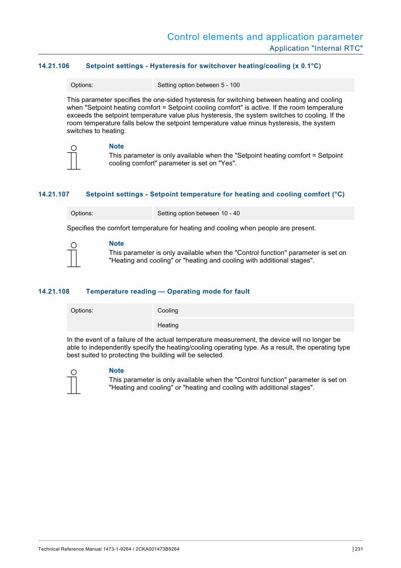
Control elements and application parameter Application "Internal RTC"
Technical Reference Manual 1473-1-9264 / 2CKA001473B9264 │231
14.21.106 Setpoint settings - Hysteresis for switchover heating/cooling (x 0.1°C)
Options: Setting option between 5 - 100
This parameter specifies the one-sided hysteresis for switching between heating and cooling when "Setpoint heating comfort = Setpoint cooling comfort" is active. If the room temperature exceeds the setpoint temperature value plus hysteresis, the system switches to cooling. If the room temperature falls below the setpoint temperature value minus hysteresis, the system switches to heating.
Note This parameter is only available when the "Setpoint heating comfort = Setpoint cooling comfort" parameter is set on "Yes".
14.21.107 Setpoint settings - Setpoint temperature for heating and cooling comfort (°C)
Options: Setting option between 10 - 40
Specifies the comfort temperature for heating and cooling when people are present.
Note This parameter is only available when the "Control function" parameter is set on "Heating and cooling" or "heating and cooling with additional stages".
14.21.108 Temperature reading — Operating mode for fault
Options: Cooling
Heating
In the event of a failure of the actual temperature measurement, the device will no longer be able to independently specify the heating/cooling operating type. As a result, the operating type best suited to protecting the building will be selected.
Note This parameter is only available when the "Control function" parameter is set on "Heating and cooling" or "heating and cooling with additional stages".
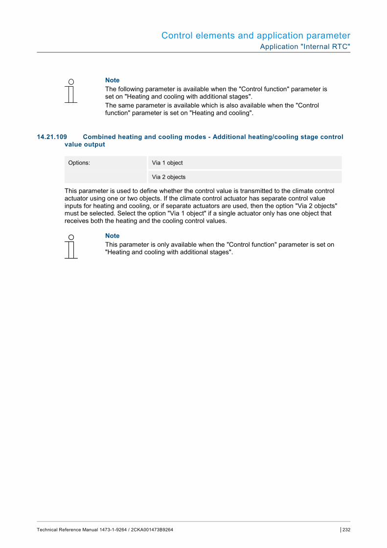
Control elements and application parameter Application "Internal RTC"
Technical Reference Manual 1473-1-9264 / 2CKA001473B9264 │232
Note The following parameter is available when the "Control function" parameter is set on "Heating and cooling with additional stages". The same parameter is available which is also available when the "Control function" parameter is set on "Heating and cooling".
14.21.109 Combined heating and cooling modes - Additional heating/cooling stage control value output
Options: Via 1 object
Via 2 objects
This parameter is used to define whether the control value is transmitted to the climate control actuator using one or two objects. If the climate control actuator has separate control value inputs for heating and cooling, or if separate actuators are used, then the option "Via 2 objects" must be selected. Select the option "Via 1 object" if a single actuator only has one object that receives both the heating and the cooling control values.
Note This parameter is only available when the "Control function" parameter is set on "Heating and cooling with additional stages".
Notes
Technical Reference Manual 1473-1-9264 / 2CKA001473B9264 │233
15 Notes

Index
Technical Reference Manual 1473-1-9264 / 2CKA001473B9264 │234
16 Index
A Access to pages .................................................................. 84 Activating mute (mite timer) ................................................. 87 Additional function of hearing loop ...................................... 18 Additional functions ........................................................... 196 Additional necessary components ....................................... 17 Addressing ......................................................................... 104 Addressing the stations ............................................... 28, 104 Alarm functions — Condensate water alarm ..................... 223 Alarm functions - Dew point alarm ..................................... 224 Alarm functions - Frost alarm temperature for HVAC and
RHCC status (°C) ................................................. 209, 224 Alarm functions - Heat alarm temperature for RHCC status
(°C) ....................................................................... 209, 224 Application
"Door communication" ............................................ 63, 171 "Fault and alarm messages" ............. 64, 91, 172, 174, 175 "Internal RTC" ......................................................... 66, 194 "Logical functions" .................................................. 66, 183 "Presence simulation" ............................................. 65, 180 "Scene actuator" ..................................................... 65, 176 "Time programs" ..................................................... 65, 182
Application ......................................................................... 226 Application "Door communication"
Page protected by PIN ................................................. 171 Ring tone volume preset [%] ........................................ 171 Speech volume preset [%] ............................................ 171 Use of door communication .......................................... 171
Application "Fault and alarm messages" Automatic archive at an acknowledge .......................... 173 Default setting for signal tone volume [%] .................... 173 Enable export ............................................................... 172 Name of message ........................................................ 174 Page PIN-protected ...................................................... 172 Signal tone for fault ....................................................... 173 Sound for alarm ............................................................ 173 Sound for hint ............................................................... 173 Type of alarm ................................................................ 174 Type of message .......................................................... 174 Use of fault and alarm messages ................................. 172
Application "Logical functions" Channel x - application ................................................. 183
Application "Presence simulation" Delay time up to activation ........................................... 181 Enable export ............................................................... 181 Page protected by PIN ................................................. 180 Setting the object type .................................................. 181 Use of presence simulation .......................................... 180
Application "Scene actuator" Light scene starts with ... .............................................. 179 Name of scene ............................................................. 179 Name of scene actuator ............................................... 176 Number of participants ................................................. 176 Number of scenes ........................................................ 176 Object type x ................................................................. 177 Object x is to be changed ............................................. 179
Overwriting scenes during download ............................176 Scene number ...............................................................179 Storing light scene.........................................................179 Telegram delay .............................................................176
Application "Time programs" Overwriting time programs ............................................182 Page protected by PIN ..................................................182
Applications Parameter .....................................................................113
Applications and application pages Configuration ...................................................................63
Assigning the door bell buttons ..........................................105
B Basic load active when controller is off ......................202, 216 Basic stage cooling ............................................................213 Basic stage cooling - Cyclic sending of the control value
(min) ..............................................................................214 Basic stage cooling - Hysteresis (x 0.1°C) .........................214 Basic stage cooling - Maximum control value (0 - 255) .....215 Basic stage cooling - Minimum control value for basic load (0
to 255) ...........................................................................215 Basic stage cooling - Mode of thre control value ...............213 Basic stage cooling - PWM cycle cooling (min) .................215 Basic stage cooling - Status object cooling ........................213 Basic stage heating ............................................................199 Basic stage heating - Control value difference for sending of
heating control value .....................................................200 Basic stage heating - Cyclic sending of the control value
(min) ..............................................................................200 Basic stage heating - Hysteresis (x 0.1°C) ........................200 Basic stage heating - Maximum control value (0 - 255) .....201 Basic stage heating - Minimum control value for basic load (0
to 255) ...........................................................................201 Basic stage heating - Mode of control value ......................199 Basic stage heating - PWM cycle heating (min).................201 Basic stage heating - Status object heating .......................199
C Call-up and editing of the favourites list ...............................83 Circuit diagrams .............................................................21, 28 Circuit diagrams and dimensional drawings .........................20 Cleaning .............................................................................112 Combined heating and cooling modes ...............................229 Combined heating and cooling modes - Heating/cooling
control value output .......................................................230 Combined heating and cooling modes - Operating mode after
reset ..............................................................................230 Combined heating and cooling modes - Switchover of
heating/cooling ..............................................................229 Commissioning
Sequence ........................................................................38 via Power-Tool ..........................................................31, 32
Communication objects Editing .............................................................................67
Connection and installation ..................................................28 Connection, installation / mounting ......................................22
Index
Technical Reference Manual 1473-1-9264 / 2CKA001473B9264 │235
Control actions of additional applications ............................ 89 Control element
"Audio control" ........................................................ 62, 164 "Blind" ..................................................................... 61, 139 "Dimmer slider" ....................................................... 60, 128 "Dimmer"................................................................. 60, 124 "Display" ................................................................. 61, 149 "Fan switch" ............................................................ 61, 142 "Page link" .............................................................. 62, 162 "RGBW operation“ .................................................. 60, 131 "Rocker switch" ....................................................... 60, 119 "RTC control element" ............................................ 61, 159 "Scene" ................................................................... 61, 147 "Switch"................................................................... 60, 113 "Value slider" .......................................................... 61, 135 Copy ............................................................................... 63 Delete ............................................................................. 62 Icon for On / icon for Off ............................................... 124
Control element "Audio control" Enable 1-bit communication object "Disable" ............... 170 Forward button ............................................................. 167 Function of the control element .................................... 164 Name of control element .............................................. 164 Number of sources ....................................................... 164 Play button .................................................................... 165 Return key .................................................................... 167 Stop button ................................................................... 166 Use of key for mute ...................................................... 168 Use of ON/OFF key ...................................................... 170 Use of pause button ..................................................... 165 Use of volume key ........................................................ 169
Control element "Blind" Enable 1-bit communication object "Disable" ............... 141 Function of the control element .................................... 139 Icon type ....................................................................... 140 Name of control element .............................................. 139 Size of the button .......................................................... 139 Status control element (icon) ... .................................... 141 Type of control .............................................................. 139
Control element "Dimmer slider" Brightness change [%] .......................................... 130, 134 Display value in control element ................................... 129 Enable 1-bit communication object "Disable" ............... 130 Icon for On / icon for Off ............................................... 128 Icon type ....................................................................... 128 Slider from .................................................................... 129 Slider sends .................................................................. 130 Status control element (icon) ... .................................... 129
Control element "Dimmer" Enable 1-bit communication object "Disable" ............... 127 Function of the control element .................................... 124 Icon for dim up/dim down ............................................. 125 Icon type ....................................................................... 124 Manner of dimming ....................................................... 126 Name of control element .............................................. 124 Position for dim up icon ................................................ 125 Size of the button .......................................................... 124 Status control element (icon) ... .................................... 125 Staus of dimming value ... ............................................ 125
Control element "Display"
Enable 1-bit communication object "Disable"................158 Function of the control element .....................................149 Name of control element ...............................................149 Option "Air pressure" — Size of the button ...................158 Option "Air pressure" — Unit .........................................158 Option "CO2" — Size of the button ...............................157 Option "CO2" — Unit .....................................................157 Option "Linear measurement display" — Display value in
control element .........................................................153 Option "Linear measurement display" — Measurement
display with colour display ................................153, 155 Option "Linear measurement display" — Object type ...154 Option "Moisture" — Size of the button .........................157 Option "Moisture" — Unit ..............................................158 Option "Rain" — Size of the button ...............................156 Option "Rain" — Text for no rain ...................................156 Option "Rain" — Text for rain ........................................156 Option "Status display" — Object type ..........................150 Option "Status display" — Size of the button ................150 Option "Temperature" — Size of the button ..................156 Option "Temperature" — Unit .......................................156 Option "Twilight" — Size of the button ..........................157 Option "Twilight" — Unit ................................................157 Option "Value display" — Object type ...........................151 Option "Value display" — Size of the button .................151 Option "Wind force" — Size of the button .....................155 Option "Wind force" — Unit ...........................................156 Type of display element ................................................149 Type of display element — Option "Brightness" ...........157 Type of display element — Option "Round measurement
display" .....................................................................155 Type of display element — Option "Wind rose" ............155
Control element "Fan switch" Deactivation of switch-off option ...................................142 Display status ................................................................145 Enable 1-bit communication object "Disable"................146 Function of the control element .....................................142 Icon type........................................................................143 Name of control element ...............................................142 Number of speed levels ................................................144 Object type ....................................................................144 Size of the button ..........................................................142
Control element "Fan switch“ Telegram is repeated every [sec.] .................................143
Control element "Page link" Enable 1-bit communication object "Disable"................163 Function of the control element .....................................162 Linked with page ...........................................................162 Name of control element ...............................................162 Size of the button ..........................................................162
Control element "RGBW operation" Display value in control element ...................................131 Enable 1-bit communication object "Disable"................134 Function of the control element .....................................131 Name of control element ...............................................131 Type of colour/white lamp .............................................131
Control element "RGBW operation“ Telegram is repeated every [sec.] .................................134
Control element "Rocker switch" Enable 1-bit communication object "Disable"................123
Index
Technical Reference Manual 1473-1-9264 / 2CKA001473B9264 │236
Function of the control element .................................... 119 Icon type ....................................................................... 119 Name of control element .............................................. 119 Object type ................................................................... 120 Size of the button .......................................................... 119 Status control element (icon/text) ... ............................. 120
Control element "RTC control element" Additional functions/objects .......................................... 159 Delay time ... after reset ............................................... 159 Display actual temperature ........................................... 160 Enable 1-bit communication object "Disable" ............... 161 Fan coil control during cooling mode ............................ 161 Fan coil control during heating mode ........................... 161 Function of the control element .................................... 159 Heating/cooling switchover ........................................... 161 Input for temperature reading ....................................... 160 Name of control element .............................................. 159 Set value is relative ...................................................... 161 Setting the temperature unit via object ......................... 161 Temperature unit .......................................................... 160
Control element "Scene" "Scene number x [1 - 64] .............................................. 148 Enable 1-bit communication object "Disable" ............... 148 Function of the control element .................................... 147 Long operation after... .................................................. 147 Name of control element .............................................. 147 Name of scene x ........................................................... 148 Number of scenes [1 - 10] ............................................ 147 Saving scene x with a long press ................................. 148 Start scene at selection ................................................ 147
Control element "Slider" Function of the control element .................................... 128 Name of control element .............................................. 128 Size of the button .......................................................... 128
Control element "Switch" Enable 1-bit communication object "Disable" ............... 118 Function of the control element .................................... 113 Icon type ....................................................................... 117 Name of control element .............................................. 113 Object type value 1 / value 2 ................................ 113, 114 Size of the button .......................................................... 113 Status control element (icon/text) ... ............................. 117 Type of switch ............................................................... 113
Control element "Value slider" Display value in control element ................................... 136 Enable 1-bit communication object "Disable" ............... 138 Function of the control element .................................... 135 Name of control element .............................................. 135 Object type ................................................................... 137 Size of the button .......................................................... 135 Slider from .................................................................... 135 Slider sends .................................................................. 136
Control elements ........................................................... 71, 72 Additional basic principles .............................................. 74 Adjustable ....................................................................... 75 Basic structures .............................................................. 73 Parameter ..................................................................... 113
Control function ................................................................. 194 Control of additional cooling stage - Cooling type ............. 228 Control of additional cooling stage - P-component (min) ... 229
Control of additional cooling stage - P-component (x 0.1°C) ......................................................................................228
Control of additional heating stage - Additional heating type ......................................................................................210
Control of additional heating stage - I-component (min) ....211 Control of additional heating stage - P-component (x 0.1°C)
......................................................................................210 Control of heating with additional stage - Temperature
difference to basic stage (x 0.1°C)................................209 Cooling control - Cooling type ............................................211 Cooling control - Extended settings ...................................212 Cooling control - I-component (min.) ..................................212 Cooling control - P-component (x 0.1°C) ...........................212
D Delay time for read telegrams after reset ...........................196 Device function...................................................................194 Device overview ...................................................................18 Dimensional drawings ..........................................................20 Dismantling ..........................................................................29
E Editing ............................................................................82, 83 Environment .........................................................................15 Establishing a speech and video connection .......................86 ETS
Busch-SmartTouch® 7'' importing product data ........33, 34 Events and image storage ...................................................88
F Fault and alarm messages ...................................................91 Firmware update ................................................................110 Floors and rooms
Editing .............................................................................56 Function
Preview ...........................................................................69
G General - Operating mode after reset ................................195 General control and display functions ............................54, 70 Group addresses
Editing .............................................................................68
H Heating control - Control value type ...................................197 Heating control — Extended settings .................................199 Heating control - Heating type............................................198 Heating control - I-component (min.)..................................199 Heating control - P-component (x 0.1°C) ...........................198 History ..................................................................................88
I Improper use ........................................................................13 Information and symbols used .............................................12 Information on protection of the environment.......................15 Initial commissioning ............................................................30 Installation
Sequence ........................................................................32 Integration into the KNX system...........................................32 Intended use ........................................................................13
Index
Technical Reference Manual 1473-1-9264 / 2CKA001473B9264 │237
K KNX settings in the Busch-SmartTouch® 7'' ........................ 33
M Maintenance ...................................................................... 112 Micro SD card (SDHC) .............................. 30, 90, 92, 98, 111 Mounting .............................................................................. 23
Hollow wall ...................................................................... 24 Solid wall ........................................................................ 25 Surface-mounted mounting frame .................................. 26
Mounting versions ............................................................... 24
N Navigation structure
Creation .................................................................... 38, 53 Notes ................................................................................. 233 Notes on the instruction manual .......................................... 11
O Old control panel box 6136/UP-500 (MD/U 1.1) .................. 27 Opening the door ................................................................. 86 Operating actions of the application .................................... 85 Operating pages
Configuration .................................................................. 58 Creating .......................................................................... 53 Creating floors ................................................................ 54 Creating rooms ......................................................... 53, 54 Editing ............................................................................. 55
Operation ....................................................................... 38, 70 Overview of KNX functions ............................................ 16, 17 Overview of types ................................................................ 17
P Panel
Basic settings ..................... 38, 39, 63, 171, 172, 180, 182 Basic structure .......................................................... 37, 53
Planning instructions ........................................................... 22 Power-Tool
overview ......................................................................... 34 plug-in ....................................................................... 32, 33 Programming (exporting) ................................................ 69 screen areas ................................................................... 35 start ........................................................................... 34, 38
Preparatory steps ................................................................ 23 Presence simulation ...................................................... 65, 89
Q Qualification of personnel .................................................... 14
R Return to the previous page ................................................ 84
S Safety .................................................................................. 12 Safety instructions ......................................................... 14, 22 Scope of supply ................................................................... 17 Send cyclic "In operation" (min) ......................................... 196 Setpoint adjustment — Maximum manual increase during
cooling mode (0 - 9°C) ................................................. 218 Setpoint adjustment — Maximum manual increase during
heating mode (0 - 9°C) ................................................. 204
Setpoint adjustment — Maximum manual reduction during cooling mode (0 - 9°C) ..................................................219
Setpoint adjustment — Maximum manual reduction during heating mode (0 - 9°C) .................................................205
Setpoint adjustment - Permanent storage of on-site operation ..............................................................................206, 220
Setpoint adjustment - Resetting of the manual adjustment for receipt of a basic setpoint .....................................205, 219
Setpoint adjustment - Resetting the manual adjustment for change of operating mode ....................................205, 219
Setpoint adjustment - Resetting the manual adjustment via object.....................................................................206, 220
Setpoint settings - Cyclic sending of the current set-point temperature (min)..................................................204, 218
Setpoint settings - Hysteresis for switchover heating/cooling ......................................................................................231
Setpoint settings - Increase for ECO cooling (°C) .............217 Setpoint settings - Increase for standby cooling (°C) .........217 Setpoint settings - Reduction for ECO heating (°C) ...........203 Setpoint settings - Reduction for standby heating (°C) ......203 Setpoint settings - Send current setpoint ...................204, 218 Setpoint settings - Setpoint for heating comfort = setpoint for
cooling comfort ..............................................................230 Setpoint settings - Setpoint temperature for cooling comfort
(°C) ...............................................................................217 Setpoint settings - Set-point temperature for frost protection
(°C) ...............................................................................204 Setpoint settings - Set-point temperature for heat protection
(°C) ...............................................................................218 Setpoint settings - Setpoint temperature for heating and
cooling comfort (°C) ......................................................231 Setpoint settings - Setpoint temperature for heating comfort
(°C) ...............................................................................203 Setting master/slave switches ......................................28, 103 Setting the ..........................................................................106 Setting the address of the indoor station............................105 Setting the address of the outdoor station .........................105 Setting the device for door communication ........................103 Settings for application .......................................................101 Settings of basic load - Minimum control value for basic load
> 0 .........................................................................202, 216 Special functions ..................................................................82 Standard flush-mounted box ................................................26 Summer compensation ......................................................224 Summer compensation - (Lower) Starting temperature for
summer compensation (°C) ..........................................226 Summer compensation - Offset of the set-point temperature
for the entry into summer compensation (x 0.1°C) .......226 Summer compensation - Offset of the set-point temperature
for the exit from summer compensation (x 0.1°C) ........227 Summer compensation - Summer compensation ..............225 Swiss flush-mounted box .....................................................27 Switching light ......................................................................87 System settings ......................................................46, 98, 112
T Table stand 83506 ...............................................................27 Target group.........................................................................14 Technical data ......................................................................19
Index
Technical Reference Manual 1473-1-9264 / 2CKA001473B9264 │238
Temperature reading - Adjustment value for internal temperature measurement (x 0.1°C) .................... 208, 222
Temperature reading - Control value for fault (0 - 255) .... 208, 223
Temperature reading - Cyclic sending of actual temperature (min) ..................................................................... 207, 222
Temperature reading — Difference of value for sending the actual temperature (x 0.1°C) ................................ 208, 222
Temperature reading - Inputs of temperature reading ...... 206, 220
Temperature reading - Inputs of weighted temperature reading .................................................................. 206, 221
Temperature reading - Monitoring time for temperature reading (0 = no monitoring) (min) ......................... 208, 223
Temperature reading - Operating mode for fault ............... 231
Temperature reading — Weighting of external measurement (0 to 100%)............................................................207, 221
Temperature reading — Weighting of external measurement 2 (0 to 100%).........................................................207, 221
Temperature reading — Weighting of internal measurement (0 to 100%)............................................................207, 221
Terminal resistor ................................................................103 Time programs .........................................................82, 83, 94 Tools (functions)...................................................................69 Transfer of PID file .............................................................111 Trimmer ..............................................................................104
U Update..........................................................................71, 110
A member of the ABB Group Busch-Jaeger Elektro GmbH PO box 58505 Lüdenscheid Freisenbergstraße 2 58513 Lüdenscheid www.BUSCH-JAEGER.com [email protected] Central sales service: Tel.: +49 2351 956-1600 Fax: +49 2351 956-1700
Notice We reserve the right to make technical changes at all times as well as changes to the contents of this document without prior notice. The detailed specifications agreed upon apply for orders. ABB accepts no responsibility for possible errors or incompleteness in this document. We reserve all rights to this document and the topics and illustrations contained therein. The document and its contents, or extracts thereof, must not be reproduced, transmitted or reused by third parties without prior written consent by ABB Copyright© 2017 Busch-Jaeger Elektro GmbH All rights reserved
Tech
nica
l Ref
eren
ce M
anua
l 14
73-1
-926
4 / 2
CK
A00
1473
B92
64