technical project description for offshore wind farms (200...
TRANSCRIPT
Technical Project Description for Offshore Wind Farms (200 MW)
Offshore Wind Farms at Vesterhav Nord, Vesterhav Syd, Sæby, Sejerø Bugt,
Smålandsfarvandet and Bornholm
April 2015

Dok. 13/97289-2 2/58
Technical Project Description for Offshore Wind Farms (200 MW) Published by Energinet.dk Published as Internet version only: Report no. 13-97289-2 Energinet.dk Tonne Kjærsvej 65 DK-7000 Fredericia Denmark Tel. +45 70 10 22 44 The report may be downloaded the Danish Energy Agency’s (Energistyrelsen) website: www.ens.dk April 2015
Dok. 13/97289-2 3/58
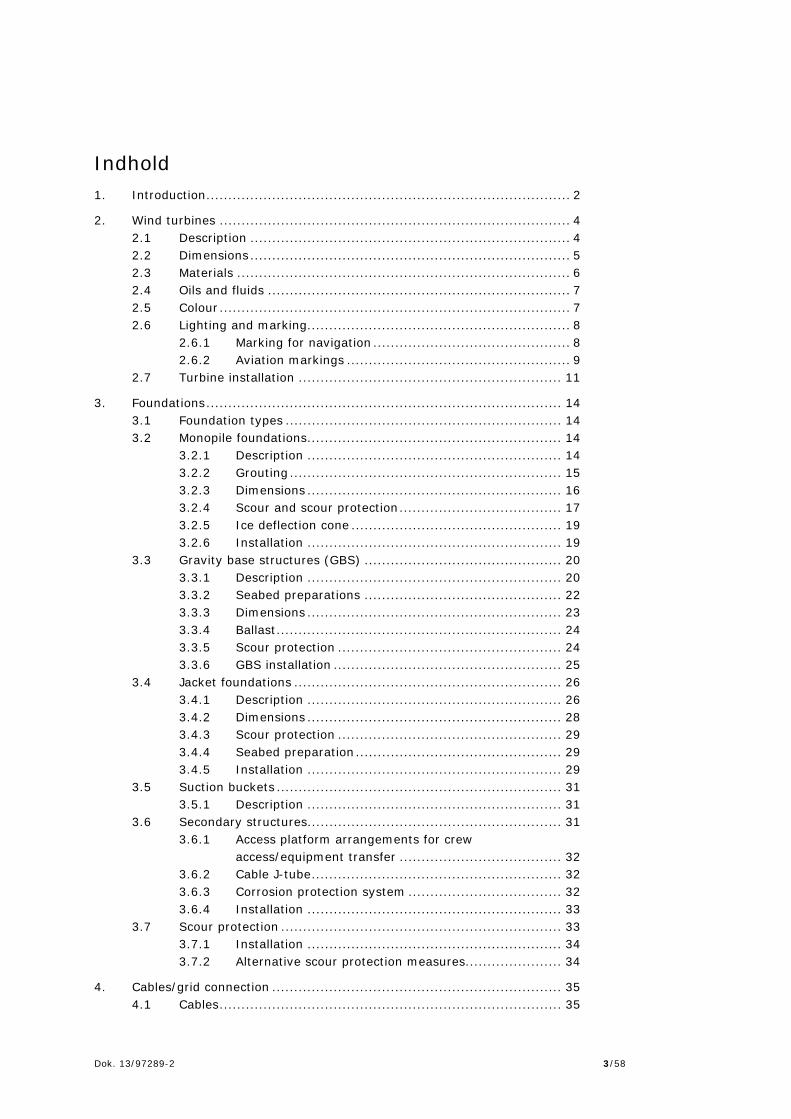
Indhold 1. Introduction ................................................................................... 2
2. Wind turbines ................................................................................ 4 2.1 Description ......................................................................... 4 2.2 Dimensions ......................................................................... 5 2.3 Materials ............................................................................ 6 2.4 Oils and fluids ..................................................................... 7 2.5 Colour ................................................................................ 7 2.6 Lighting and marking ............................................................ 8
2.6.1 Marking for navigation ............................................. 8 2.6.2 Aviation markings ................................................... 9
2.7 Turbine installation ............................................................ 11
3. Foundations ................................................................................. 14 3.1 Foundation types ............................................................... 14 3.2 Monopile foundations .......................................................... 14
3.2.1 Description .......................................................... 14 3.2.2 Grouting .............................................................. 15 3.2.3 Dimensions .......................................................... 16 3.2.4 Scour and scour protection ..................................... 17 3.2.5 Ice deflection cone ................................................ 19 3.2.6 Installation .......................................................... 19
3.3 Gravity base structures (GBS) ............................................. 20 3.3.1 Description .......................................................... 20 3.3.2 Seabed preparations ............................................. 22 3.3.3 Dimensions .......................................................... 23 3.3.4 Ballast ................................................................. 24 3.3.5 Scour protection ................................................... 24 3.3.6 GBS installation .................................................... 25
3.4 Jacket foundations ............................................................. 26 3.4.1 Description .......................................................... 26 3.4.2 Dimensions .......................................................... 28 3.4.3 Scour protection ................................................... 29 3.4.4 Seabed preparation ............................................... 29 3.4.5 Installation .......................................................... 29
3.5 Suction buckets ................................................................. 31 3.5.1 Description .......................................................... 31
3.6 Secondary structures.......................................................... 31 3.6.1 Access platform arrangements for crew
access/equipment transfer ..................................... 32 3.6.2 Cable J-tube ......................................................... 32 3.6.3 Corrosion protection system ................................... 32 3.6.4 Installation .......................................................... 33
3.7 Scour protection ................................................................ 33 3.7.1 Installation .......................................................... 34 3.7.2 Alternative scour protection measures...................... 34
4. Cables/grid connection .................................................................. 35 4.1 Cables .............................................................................. 35
Dok. 13/97289-2 4/58
4.2 Installation of Cables .......................................................... 35 4.3 Cable burial by Jetting ........................................................ 36 4.4 Cable burial by plough ........................................................ 37 4.5 Vertical injector ................................................................. 38 4.6 Pre-excavated trenches ...................................................... 39 4.7 Protection by rock cover ..................................................... 40
5. Noise .......................................................................................... 41 5.1 Noise emissions from installation of monopiles ....................... 41 5.2 Operational airborne noise emissions .................................... 41
6. Offshore Construction.................................................................... 43 6.1 Construction issues in shallow waters ................................... 43
6.1.1 Monopile foundation .............................................. 43 6.1.2 Gravity base structure (GBS) .................................. 44 6.1.3 Jacket foundation .................................................. 45 6.1.4 Suction bucket ..................................................... 46
6.2 Access to site and safety zones ............................................ 46 6.3 Helicopter ......................................................................... 46 6.4 Lighting and markings during construction ............................. 47 6.5 Offshore construction programme ........................................ 47 6.6 Emissions and discharges .................................................... 48 6.7 Access to site and safety zones during service life ................... 48
7. Operation and maintenance ........................................................... 49 7.1 Scheduled inspection/maintenance ....................................... 49 7.2 Periodic overhauls .............................................................. 49 7.3 Unscheduled maintenance ................................................... 49 7.4 Consumables .................................................................... 50
8. Decommissioning ......................................................................... 51 8.1 Extent of decommissioning .................................................. 51 8.2 Decommissioning an offshore wind farm................................ 51 8.3 Disposal or re-use of components ......................................... 52
9. References .................................................................................. 54

Dok. 13/97289-2 5/58

Dok. 13/97289-2 2/58
1. Introduction On 22 March 1012 a broad political majority of the Danish Parliament agreed to establish 450 MW new nearshore wind farms. The overall target was July 14th 2014, as a consequence of a political agreement in the Danish Parliament, reduced from 450 MW to 350 MW. Energinet.dk, with injunction from the Danish Energy Agency (DEA), is designated to carry out Environmental Impact Assessment (EIA) as well as geophysical and Metocean (wind, current and wave) investigations. This document outlines the proposed technical aspects of the offshore development of the nearshore wind farms. This includes: wind turbines (WTG) and foundations, sub-sea internal array - and export cables. Each technical component will be addressed, with respect to construction (i.e. installation), operation and maintenance and decommissioning. It is planned to develop a total of 450 MW (in July 2014 reduced to 350 MW) wind power to be located at up to six offshore sites in Denmark. The sites are: Vesterhav Syd, Vesterhav Nord, Sæby, Sejerø Bugt, Smålandsfarvandet, and Bornholm (Figure 1). The wind farm sites are located at least 4 km off the coast, and each site covers an area of approx. 60 km2 (approx. 45 km2 for Bornholm). Each site may hold an installed effect of up to a maximum of 200 MW, apart from Bornholm which may hold up to a maximum of 50 MW.
Figure 1 Location of the six nearshore wind farm sites

Dok. 13/97289-2 3/58
The site-specific offshore project characteristics for each of the six wind farm sites appear from six appendices to this report:
Appendix 1: Vesterhav Syd Offshore Wind Farm Appendix 2: Vesterhav Nord Offshore Wind Farm Appendix 3: Sæby Offshore Wind Farm Appendix 4: Sejerø Bugt Offshore Wind Farm Appendix 5: Smålandsfarvandet Offshore Wind Farm Appendix 6: Bornholm Offshore Wind Farm.
Dok. 13/97289-2 4/58
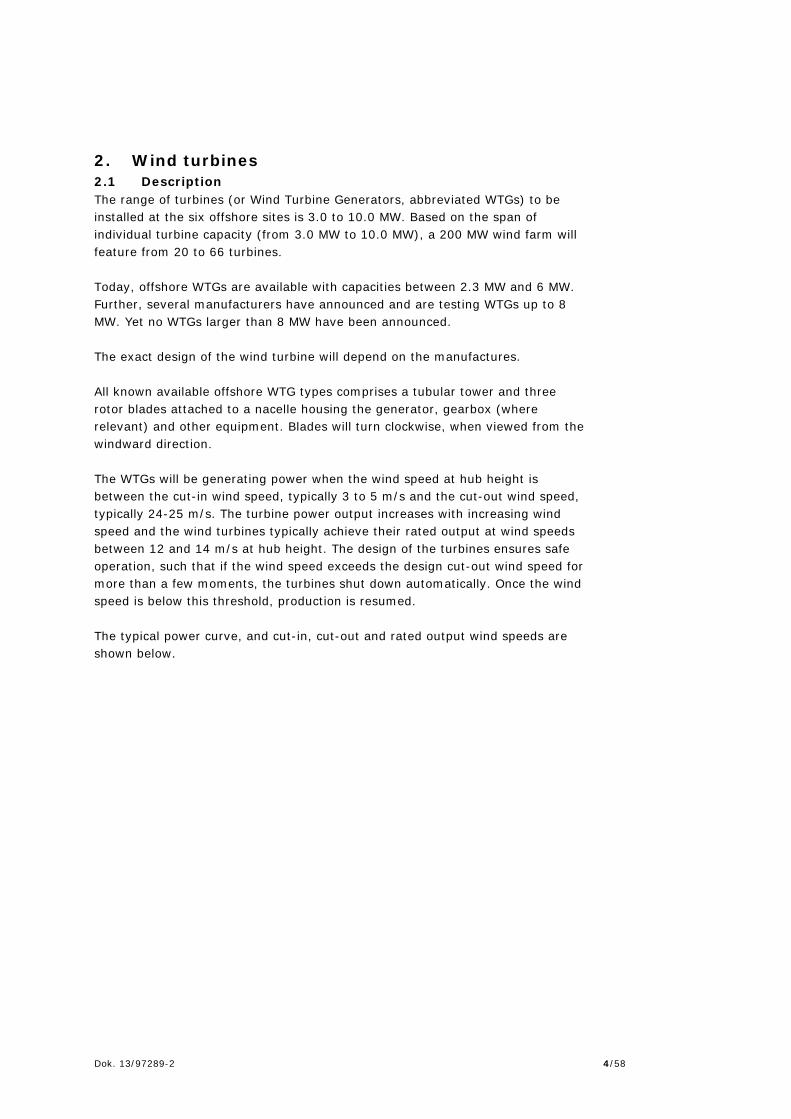
2. Wind turbines 2.1 Description The range of turbines (or Wind Turbine Generators, abbreviated WTGs) to be installed at the six offshore sites is 3.0 to 10.0 MW. Based on the span of individual turbine capacity (from 3.0 MW to 10.0 MW), a 200 MW wind farm will feature from 20 to 66 turbines. Today, offshore WTGs are available with capacities between 2.3 MW and 6 MW. Further, several manufacturers have announced and are testing WTGs up to 8 MW. Yet no WTGs larger than 8 MW have been announced. The exact design of the wind turbine will depend on the manufactures. All known available offshore WTG types comprises a tubular tower and three rotor blades attached to a nacelle housing the generator, gearbox (where relevant) and other equipment. Blades will turn clockwise, when viewed from the windward direction. The WTGs will be generating power when the wind speed at hub height is between the cut-in wind speed, typically 3 to 5 m/s and the cut-out wind speed, typically 24-25 m/s. The turbine power output increases with increasing wind speed and the wind turbines typically achieve their rated output at wind speeds between 12 and 14 m/s at hub height. The design of the turbines ensures safe operation, such that if the wind speed exceeds the design cut-out wind speed for more than a few moments, the turbines shut down automatically. Once the wind speed is below this threshold, production is resumed. The typical power curve, and cut-in, cut-out and rated output wind speeds are shown below.

Dok. 13/97289-2 5/58
Figure 2 Typical WTG power curve
2.2 Dimensions The dimensions of the turbines are not expected to exceed a maximum tip height of 220m above mean sea level for the largest turbine size (10 MW). Assumptions on WTG dimensions are presented in Table 1. The assumptions are based on information on currently available WTGs on the market and announced WTGs (Energinet.dk 2014a, 2014b, NIRAS 2014).
Table 1 Approximate WTG dimensions used as assumptions in the EIA
Turbine capacity
(MW)
Rotor diameter
(m)
Total height above MSL
(m)
Hub height above MSL
(m)
Swept area
(m2) 3.0 112 137 81 9,852 3.6 120 141.6 81.6 11,500 4.0 130 155 90 13,300 6.0 154 179 102 18,600 8.0 164 189 107 21,124 10.0 190 220 125 28,400
The air gap between Mean Seal Level (MSL) and the lower wing tip will be determined based on the actual project. However the Danish Maritime Authority (DMA) will request a minimum of 20 metres between the Highest Astronomical Tide (HAT) and the lower wing tip. The determining factors for acceptable air gap will be:
Regulatory requirements
Dok. 13/97289-2 6/58
Sufficient air gap between the access platform on the turbine foundation and the blade tip. (Typically the elevation of the platform is determined by the extreme wave height)
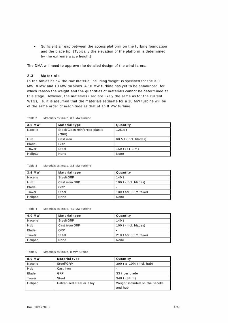
The DMA will need to approve the detailed design of the wind farms. 2.3 Materials In the tables below the raw material including weight is specified for the 3.0 MW, 8 MW and 10 MW turbines. A 10 MW turbine has yet to be announced, for which reason the weight and the quantities of materials cannot be determined at this stage. However, the materials used are likely the same as for the current WTGs, i.e. it is assumed that the materials estimate for a 10 MW turbine will be of the same order of magnitude as that of an 8 MW turbine.
Table 2 Materials estimate, 3.0 MW turbine
3.0 MW Material type Quantity Nacelle Steel/Glass reinforced plastic
(GRP) 125.4 t
Hub Cast iron 68.5 t (incl. blades) Blade GRP - Tower Steel 150 t (61.8 m) Helipad None None
Table 3 Materials estimate, 3.6 MW turbine
3.6 MW Material type Quantity Nacelle Steel/GRP 140 t Hub Cast iron/GRP 100 t (incl. blades) Blade GRP - Tower Steel 180 t for 60 m tower Helipad None None
Table 4 Materials estimate, 4.0 MW turbine
4.0 MW Material type Quantity Nacelle Steel/GRP 140 t Hub Cast iron/GRP 100 t (incl. blades) Blade GRP - Tower Steel 210 t for 68 m tower Helipad None None
Table 5 Materials estimate, 8 MW turbine
8.0 MW Material type Quantity Nacelle Steel/GRP 390 t ± 10% (incl. hub) Hub Cast iron - Blade GRP 33 t per blade Tower Steel 340 t (84 m) Helipad Galvanised steel or alloy Weight included on the nacelle
and hub
Dok. 13/97289-2 7/58
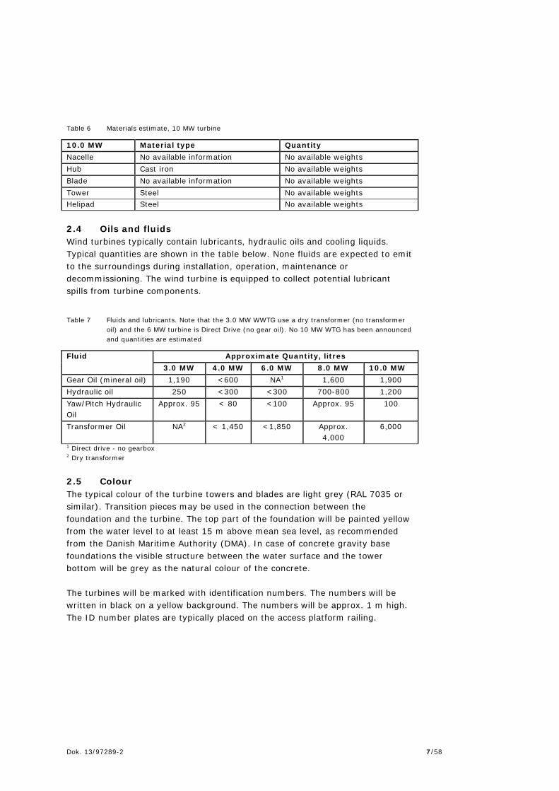
Table 6 Materials estimate, 10 MW turbine
10.0 MW Material type Quantity Nacelle No available information No available weights Hub Cast iron No available weights Blade No available information No available weights Tower Steel No available weights Helipad Steel No available weights 2.4 Oils and fluids Wind turbines typically contain lubricants, hydraulic oils and cooling liquids. Typical quantities are shown in the table below. None fluids are expected to emit to the surroundings during installation, operation, maintenance or decommissioning. The wind turbine is equipped to collect potential lubricant spills from turbine components.
Table 7 Fluids and lubricants. Note that the 3.0 MW WWTG use a dry transformer (no transformer oil) and the 6 MW turbine is Direct Drive (no gear oil). No 10 MW WTG has been announced and quantities are estimated
Fluid Approximate Quantity, litres 3.0 MW 4.0 MW 6.0 MW 8.0 MW 10.0 MW
Gear Oil (mineral oil) 1,190 <600 NA1 1,600 1,900 Hydraulic oil 250 <300 <300 700-800 1,200 Yaw/Pitch Hydraulic Oil
Approx. 95 < 80 <100 Approx. 95 100
Transformer Oil NA2 < 1,450 <1,850 Approx. 4,000
6,000
1 Direct drive - no gearbox 2 Dry transformer 2.5 Colour The typical colour of the turbine towers and blades are light grey (RAL 7035 or similar). Transition pieces may be used in the connection between the foundation and the turbine. The top part of the foundation will be painted yellow from the water level to at least 15 m above mean sea level, as recommended from the Danish Maritime Authority (DMA). In case of concrete gravity base foundations the visible structure between the water surface and the tower bottom will be grey as the natural colour of the concrete. The turbines will be marked with identification numbers. The numbers will be written in black on a yellow background. The numbers will be approx. 1 m high. The ID number plates are typically placed on the access platform railing.

Dok. 13/97289-2 8/58
Figure 3 Identification makings on the foundations for the Anholt offshore wind farm. Photo courtesy
of Jumbo
2.6 Lighting and marking The wind turbines must exhibit distinguishing markings visible for vessels and aircrafts in accordance with requirements by the Danish Maritime Authority (DMA) and the Danish Transport Authority (DTA), respectively. The light markings for aviation as well as for shipping and navigation will most likely be required to work synchronously. The anticipated requirements for lights and markings are described below. However, the actual requirements in relation to lighting will be determined by the DMA and the DTA when the layout of the wind farm and height of the wind turbines have been finally decided. 2.6.1 Marking for navigation The marking with light on the turbines in relation to shipping and navigation is expected to comply with the following description, but must be approved by the DMA when the final park layout has been decided, and in due time before construction. Each wind farm will be evaluated separately and markings will depend on site specific conditions. The markings described below are standard descriptions where deviations and special conditions can be requested from the DMA.
All turbines placed in the corners and at sharp bends along the peripheral (significant peripheral structures = SPS) of the wind farm, shall be marked with a yellow light. Additional turbines along the peripheral shall be marked, so that there will be a maximum distance between SPS defined turbines on 2 nautical miles.
The yellow light shall be visible for 180 degrees along the peripheral and
for 210-270 degrees for the corner turbines (typically located around 5-10m up on the transition piece). The light shall be flashing synchronously with 3 flashes per 10 second and with an effective reach of at least 5 nautical miles. Within the wind farm the individual turbines will not be marked.
The top part of the foundation (e.g. the transition piece) must be
painted yellow from sea surface to 15 m above mean sea level. Each turbine should be numbered (identification number) normally using of

Dok. 13/97289-2 9/58
black number on a yellow background. Indirect light should illuminate the part of the yellow painted section with the turbine identification number.
The marking of the individual wind farm must be expected to be
synchronised with potential adjacent wind farms.
Requirements from the Danish Maritime Authority for Racon can be expected, depending on the exact location of the wind turbines, e.g. northern part of Vesterhav Nord Wind Farm.
During construction the complete construction area shall be marked with
yellow lighted buoys with a reach of at least 2 nautical miles. Details on the requirements for the positions and number of buoys shall be agreed with the Danish Maritime Authority.
In relation to shipping and navigation the marking and lighting
requirements are independent of wind turbine size. 2.6.2 Aviation markings Aviation markings must be approved by the Danish Transport Authority (DTA). New regulations on aviation markings of wind turbines (BL 3-11, 2nd edition of 28/02/2014) entered into force on 28 March 2014 and provide details on the requirements to aviation markings and approval procedures. The standards and recommendations described below are specified in the BL 3-11 as well as in guidance material. The requirements will differ between the 3 MW and the 10 MW turbines due to differences in height. For offshore wind farms with a turbine height above 100 m alternative measures may be agreed with the DTA. The BL 3-11 does not contain fixed regulations for aviation markings for turbines with heights above 150 m. This group of turbines must be approved individually based on specific solutions and safety issues. For these projects the aviation marking will generally be approved if they follow the guidelines in BL 3-11, which is summarized below. For all offshore wind farms in Denmark the following standards apply:
Blades, nacelle and the top 2/3 of the tower must be white/light grey (RAL 7035) according to CIE-standards (International Commission on Illumination).
There must be a regulator for the light intensity and a measurement of
the meteorological visibility, so that the light can be adjusted up and down depending on visibility.
The light shall be visible from every direction 360 degrees horizontal
around the nacelle, which requires two lanterns to be installed on each nacelle.

Dok. 13/97289-2 10/58
For offshore turbines with a total height of 100 - 150 m (covering the 3.0 – 5.0 MW turbines) the following standards apply (marking in top of nacelle):
Turbines placed in the corners and at sharp bends along the peripheral (significant peripheral structures = SPS) of the wind farm, must be marked with medium intensity flashing red light, 2,000 candelas. The light shall be placed on the top of the nacelle and shall be visible from every direction 360 degrees horizontal around the nacelle, which require two lanterns to be installed on each nacelle.
Additional turbines along the peripheral, and inside the wind farm area,
shall be lit with fixed red light of low intensity (10 candelas as a minimum) day and night. The light shall be placed on the top of the nacelle and shall be visible from every direction 360 degrees horizontal around the nacelle, which require two lanterns to be installed on each nacelle.
As a standard requirement, the guidelines are valid if the distance
between the turbines marked with medium intensity lights does not exceed 900 m. If this distance is exceeded, the final requirements for aviation marking must be agreed with the Danish Transport Authority, in due time before construction.
For turbines with a total height above150 m (covering the 6.0, 8.0 and 10.0 MW turbines) the following apply:
Turbines placed in the corners and at sharp bends along the peripheral (significant peripheral structures = SPS) of the wind farm, must be marked with medium intensity white lights, 20,000 candelas during day time, and medium intensity flashing red light, 2,000 candelas during night time, at the top of the nacelle.
Additional turbines along the peripheral, and inside the wind farm area,
shall be lit with fixed red light of low intensity (10 candelas as a minimum) day and night. The light shall be placed on the top of the nacelle and shall be visible from every direction 360 degrees horizontal around the nacelle, which most likely require two lanterns to be installed on each nacelle.
As a standard requirement, the guidelines are valid if the distance
between the turbines does not exceed 900 m. This distance will most likely be exceed using a 10 MW turbine, and therefore the final requirements for aviation marking must be agreed with the Danish Transport Authority, in due time before construction. Most likely, it will be required that all the turbines along the peripheral of the wind farm must be marked with medium intensity white lights, 20,000 candelas during day time, and medium intensity flashing red light, 2,000 candelas during night time (the same requirements as for turbines placed in corners and at sharp bends along the peripheral).

Dok. 13/97289-2 11/58
Furthermore, a red solid light with an intensity of 32 candelas should be placed on an inter-mediate level (halfway between nacelle and mean sea level), at all turbines. Since the light should be visible from all directions, it will probably require 3 fixed lights (spacing of 120 degrees) at each turbine.
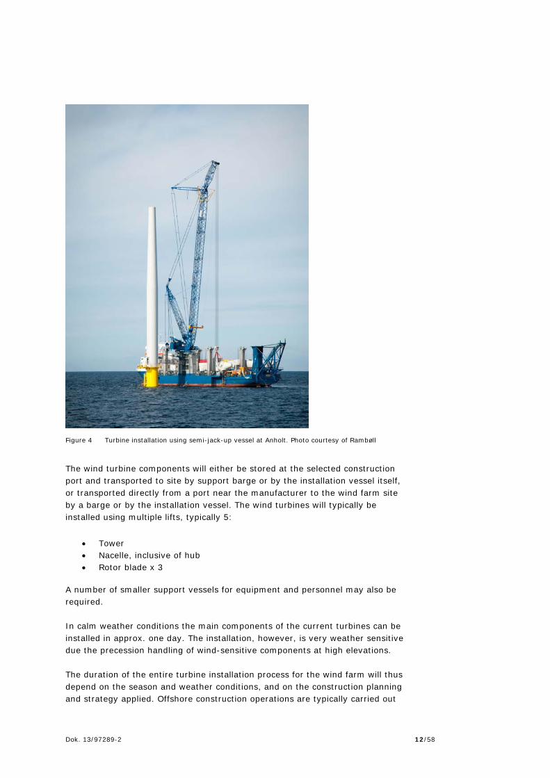
If cranes of 100-150 m height will be used during construction, these shall be marked with fixed red light of low intensity (10 candelas as a minimum). 2.7 Turbine installation Although offshore contractors use varying construction techniques, the installation of the wind turbines will typically require one or more jack-up vessels. Jack-up vessels has the ability of lowering legs onto – and into - the seabed and lift their hull out of the water and create a stable working platform. Alternatively semi-jack-up vessels may be used (where the hull remains floating but is stabilized by posts or “spuds”, lowered into the seabed), to ensure the stability required for the operation. The bases of the legs, known as spud cans can cover an area of up to 575 m2. The legs may penetrate into the seabed depending on seabed properties. The foot prints will be left to in-fill naturally. When jacking out of the seabed, seabed material may be whirled into the water and may be transported away (suspension) from its site of origin.
Dok. 13/97289-2 12/58
Figure 4 Turbine installation using semi-jack-up vessel at Anholt. Photo courtesy of Rambøll
The wind turbine components will either be stored at the selected construction port and transported to site by support barge or by the installation vessel itself, or transported directly from a port near the manufacturer to the wind farm site by a barge or by the installation vessel. The wind turbines will typically be installed using multiple lifts, typically 5:
Tower Nacelle, inclusive of hub Rotor blade x 3
A number of smaller support vessels for equipment and personnel may also be required. In calm weather conditions the main components of the current turbines can be installed in approx. one day. The installation, however, is very weather sensitive due the precession handling of wind-sensitive components at high elevations. The duration of the entire turbine installation process for the wind farm will thus depend on the season and weather conditions, and on the construction planning and strategy applied. Offshore construction operations are typically carried out

Dok. 13/97289-2 13/58
24 hours a day and 7 days a week to maximize the utilization of favourable weather windows and costly equipment and staff. Following installation and grid connection, the wind turbines will be tested and commissioned and the turbines will be available to generate electricity. Regarding issues relating to turbine installation in shallow waters, refer to Chapter 6.

Dok. 13/97289-2 14/58
3. Foundations 3.1 Foundation types The wind turbines will be supported by foundations fixed to the seabed. It is expected that the foundations will comprise one of the following options:
Steel monopile foundation Concrete gravity base structure (GBS) Jacket foundation Suction buckets
The dimensions and quantities given in this chapter are rough estimates based on experiences from similar projects and basic calculations for the purpose of being able to define worst case scenarios for the six nearshore wind farms. It is not based on actual engineering or design works. It should be noted that no 10 MW WTGs have been announced. The degree of accuracy of the foundation estimates for 10 MW WTGs is therefore subject to uncertainty. Finally, no 7 MW or larger WTG have to date been installed in true offshore conditions, meaning that there is little factual information available on which to base the estimates. 3.2 Monopile foundations 3.2.1 Description Monopile foundations are by far the most common type of foundation and have been used for 70-80 % of all offshore WTGs in operation today. Monopile foundations primarily consist of a tubular steel structure which is driven into the seabed.
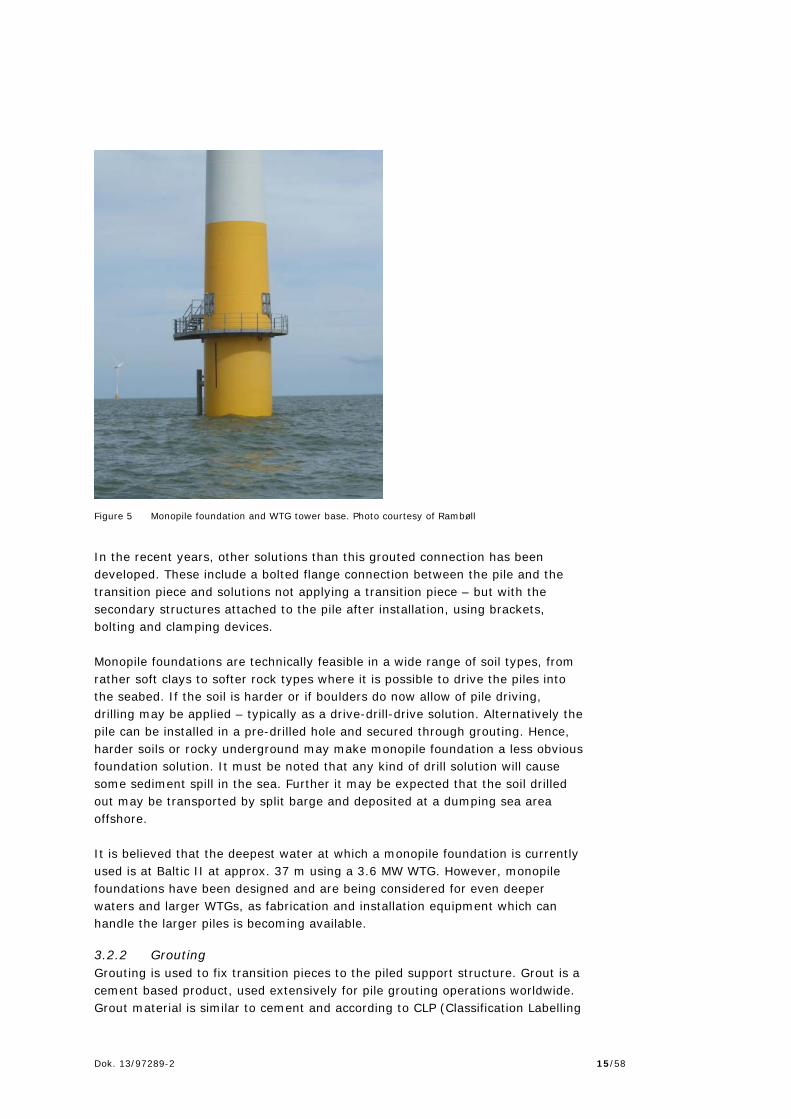
As the monopile is driven into the seabed the top of the pile may be damaged due to the action of the pile driving hammer used to install it. A further issue is that the pile may not be perfectly vertical – and the WTG mounting flange perfectly horizontal – after installation. Finally, the foundation must – in addition to the WTG itself – support various secondary structures, such as platforms, ladders, boat landing, J-tubes etc. These elements cannot be attached to the pile during driving, as the severe accelerations would damage them. To account for this, most of the monopile foundations include a transition piece – a steel sleeve of a slightly larger diameter than the pile, which is lowered over the pile and aligned to the required verticality. The void between the transition piece and the pile is then filled with grout. After the grout is cured, the WTG can be mounted. The transition piece also supports the secondary structures.
Dok. 13/97289-2 15/58
Figure 5 Monopile foundation and WTG tower base. Photo courtesy of Rambøll
In the recent years, other solutions than this grouted connection has been developed. These include a bolted flange connection between the pile and the transition piece and solutions not applying a transition piece – but with the secondary structures attached to the pile after installation, using brackets, bolting and clamping devices. Monopile foundations are technically feasible in a wide range of soil types, from rather soft clays to softer rock types where it is possible to drive the piles into the seabed. If the soil is harder or if boulders do now allow of pile driving, drilling may be applied – typically as a drive-drill-drive solution. Alternatively the pile can be installed in a pre-drilled hole and secured through grouting. Hence, harder soils or rocky underground may make monopile foundation a less obvious foundation solution. It must be noted that any kind of drill solution will cause some sediment spill in the sea. Further it may be expected that the soil drilled out may be transported by split barge and deposited at a dumping sea area offshore. It is believed that the deepest water at which a monopile foundation is currently used is at Baltic II at approx. 37 m using a 3.6 MW WTG. However, monopile foundations have been designed and are being considered for even deeper waters and larger WTGs, as fabrication and installation equipment which can handle the larger piles is becoming available.
3.2.2 Grouting Grouting is used to fix transition pieces to the piled support structure. Grout is a cement based product, used extensively for pile grouting operations worldwide. Grout material is similar to cement and according to CLP (Classification Labelling

Dok. 13/97289-2 16/58
and Packaging) cement it is classified as a dangerous substances to humans (H315/318/335). The core of grout material (e.g. Densit® Ducorit® or BASF MasterFlow®) is the binder. The binder is mixed with quartz sand or bauxite in order to obtain the strength and stiffness of the product. The grout normally used would conform to the relevant environmental standards. The grout will either be mixed in large tanks aboard the installation vessel, or mixed ashore and transported to site. The grout is likely to be pumped through a series of grout tubes previously installed in the pile, so that the grout is introduced directly between the pile and the walls of the transition piece. Methods will be adopted to ensure that the release of grout into the surrounding environment is minimized. However some grout may be released as fugitive emissions during the process. A worst-case conservative estimate of 5 %, (up to 60t) is assumed for the complete project.
3.2.3 Dimensions Monopiles are typically designed individually to account for the physical conditions; i.e. soil conditions and water depth etc. at the exact position where it is going to be installed, as well as the currents, wave climate, ice conditions at the site – in addition to the WTG loads and eigenfrequency requirements. Subsequently, the dimensions are very much dependent on the actual conditions. However, the diameter of the top of the monopile foundation will be identical to the WTG tower mounting flange, which for the currently available 3.3 MW turbine is 4.5 m and for the 7-8 MW machines 6.5-7 m. Larger pile diameters may be required and if so, a conical section is used. The larger diameters would be increasingly relevant for larger turbines, deeper water and softer soil. The penetration depth depends on the turbine loads, water depth, wave loads, ice loads and soil conditions and will vary considerably to account for the site-specific circumstances. Soil conditions alone may cause a weight difference of up to 15-25 %. For the 3.3 MW WTG at 5 m of water depth with favourable soil conditions, penetrations may be of the order of 20m. For the 8 MW WTG at 25m of water in soft soil, 50m or more may be required. However, if very deep penetrations are required it may be difficult to drive the pile to the desired depth, in which case, other foundation solutions must be considered. Further, for the larger WTG (7 MW – 10 MW) in deep water and soft soil, the overall mass of the required pile may come close to or exceed the lifting capabilities of the current jack-up installation vessels (1,200 – 1,500 t), which limits the options to install the piles. Table 8 gives the estimated dimensions for five different capacities of WTGs for water depths ranging between 5 and 25 m.
Dok. 13/97289-2 17/58
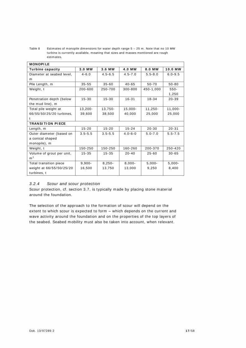
Table 8 Estimates of monopile dimensions for water depth range 5 – 25 m. Note that no 10 MW turbine is currently available, meaning that sizes and masses mentioned are rough estimates.
MONOPILE Turbine capacity 3.0 MW 3.6 MW 4.0 MW 8.0 MW 10.0 MW Diameter at seabed level, m
4-6.0 4.5-6.5 4.5-7.0 5.5-8.0 6.0-9.5
Pile Length, m 35-55 35-60 40-65 50-70 50-80 Weight, t 200-600 250-700 300-800 450-1,000 550-
1,250 Penetration depth (below the mud line), m
15-30 15-30 16-31 18-34 20-39
Total pile weight at 66/55/50/25/20 turbines, t
13,200-39,600
13,750-38,500
15,000-40,000
11,250-25,000
11,000-25,000
TRANSITION PIECE Length, m 15-20 15-20 15-24 20-30 20-31 Outer diameter (based on a conical shaped monopile), m
3.5-5.5 3.5-5.5 4.0-6-0 5.0-7.0 5.5-7.5
Weight, t 150-250 150-250 160-260 200-370 250-420 Volume of grout per unit, m3
15-35 15-35 20-40 25-60 30-65
Total transition piece weight at 66/55/50/25/20 turbines, t
9,900-16,500
8,250-13,750
8,000-13,000
5,000-9,250
5,000-8,400
3.2.4 Scour and scour protection Scour protection, cf. section 3.7, is typically made by placing stone material around the foundation. The selection of the approach to the formation of scour will depend on the extent to which scour is expected to form – which depends on the current and wave activity around the foundation and on the properties of the top layers of the seabed. Seabed mobility must also be taken into account, when relevant.

Dok. 13/97289-2 18/58
Figure 6 Principle sketch of a monopile foundation with scour protection. Illustration courtesy of
Rambøll
In the below table the estimated extent and quantities of typical scour protection systems for monopiles are shown. The measurements and quantities are rough estimates, as it varies significantly according to the specific circumstances including installation methods used.
Table 9 Estimates of scour protection extent and quantities.
SCOUR PROTECTION Turbine capacity 3.0 MW 3.6 MW 4.0 MW 8.0 MW 10.0 MW Volume per foundation, m³
2,100-2,200
2,100-2,200
2,500-2,600
3,000-3,100
3,500-3,600
Footprint per foundation, m2
1,500-1,600
1,500-1,600
1,600-1,700
1,650-1,750
2,000-2,100
Total scour volume at 66/55/50/25/20 turbines, m3
139,000-145,000
116,000-121-000
125,000-130,000
75,000-78,000
70,000-72,000
Total footprint at 66/55/50/25/20 turbines, m2
99,000-106,000
83,000-88,000
80,000-85,000
41,000-44-000
40-000-42,000
Dok. 13/97289-2 19/58
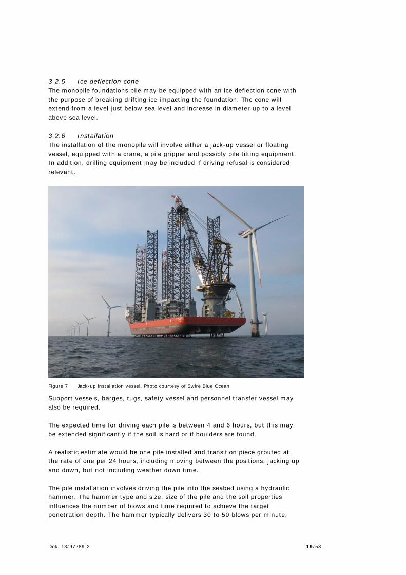
3.2.5 Ice deflection cone The monopile foundations pile may be equipped with an ice deflection cone with the purpose of breaking drifting ice impacting the foundation. The cone will extend from a level just below sea level and increase in diameter up to a level above sea level. 3.2.6 Installation The installation of the monopile will involve either a jack-up vessel or floating vessel, equipped with a crane, a pile gripper and possibly pile tilting equipment. In addition, drilling equipment may be included if driving refusal is considered relevant.
Figure 7 Jack-up installation vessel. Photo courtesy of Swire Blue Ocean
Support vessels, barges, tugs, safety vessel and personnel transfer vessel may also be required. The expected time for driving each pile is between 4 and 6 hours, but this may be extended significantly if the soil is hard or if boulders are found. A realistic estimate would be one pile installed and transition piece grouted at the rate of one per 24 hours, including moving between the positions, jacking up and down, but not including weather down time. The pile installation involves driving the pile into the seabed using a hydraulic hammer. The hammer type and size, size of the pile and the soil properties influences the number of blows and time required to achieve the target penetration depth. The hammer typically delivers 30 to 50 blows per minute,

Dok. 13/97289-2 20/58
dependent on size and type (the larger the hammer the fewer blows per minute). On average the installation of a pile can be expected to require 4,000 to 6,000 hammer blows. Often the top layers of seabed soil are relatively soft and it must be expected that the blow count per meter is the lowest and the penetration achieved per hammer blow is the highest early in the process. Even if the deeper soil layers are soft the friction between the pile and the soil means that as the pile advances it experiences more resistance. Subsequently the advance per blow decreases. Towards the end on the driving process, the advance of 1m of penetration may require approx. 200 blows. It will be important that only the appropriate driving energy and force is applied. If excessive force is applied the pile may buckle or experience fatigue damage. Subsequently, if the advance slows down and the pile refuses to penetrate further or advance slows down significantly before full penetration is achieved (due to hard soil layers or boulders) it may be necessary to use drilling equipment to drill out the soil inside the pile to penetrate or remove the obstruction before pile driving is resumed. The seabed material removed from inside the piles during the drilling is typically disposed of within the wind farm area, adjacent to each location from where the material was derived, where it is dispersed by current and waves. If this cannot be allowed, the spoils can be collected and disposed of at an appropriate disposal site. 3.3 Gravity base structures (GBS) 3.3.1 Description GBS is a support structure held in place by gravity. GBS foundations have been used for offshore wind farms in Danish, Swedish and Belgian waters for turbines ranging from 450 kW to 5 MW. GBS foundations are suitable for reasonably firm seabed conditions and are especially relevant in case of relatively larger ice loads. Two basic types have been used and are included here as examples of GBS foundations; the flat base, open caisson type and the conical type. Flat base, open caisson GBS Flat base, open caisson GBS foundations have been used for several Danish and Swedish offshore wind projects. This type of foundation consists of a base plate with open ballast chambers and a central column onto which the WTG tower is bolted. After the structure is placed at the desired position the chambers are filled with ballast, typically heavy rock types. Open caisson GBS foundations require a relatively firm soil base, and for several projects removal of soft sediment has been required. GBS foundation does not
Dok. 13/97289-2 21/58
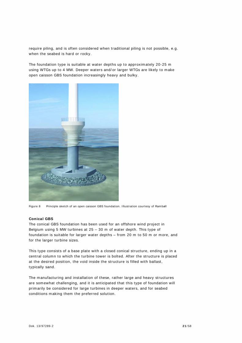
require piling, and is often considered when traditional piling is not possible, e.g. when the seabed is hard or rocky. The foundation type is suitable at water depths up to approximately 20-25 m using WTGs up to 4 MW. Deeper waters and/or larger WTGs are likely to make open caisson GBS foundation increasingly heavy and bulky.
Figure 8 Principle sketch of an open caisson GBS foundation. Illustration courtesy of Rambøll
Conical GBS The conical GBS foundation has been used for an offshore wind project in Belgium using 5 MW turbines at 25 – 30 m of water depth. This type of foundation is suitable for larger water depths – from 20 m to 50 m or more, and for the larger turbine sizes. This type consists of a base plate with a closed conical structure, ending up in a central column to which the turbine tower is bolted. After the structure is placed at the desired position, the void inside the structure is filled with ballast, typically sand. The manufacturing and installation of these, rather large and heavy structures are somewhat challenging, and it is anticipated that this type of foundation will primarily be considered for large turbines in deeper waters, and for seabed conditions making them the preferred solution.

Dok. 13/97289-2 22/58
Figure 9 Principle sketch of a conical GBS foundation. Illustration courtesy of Rambøll
For both types, a steel skirt under the base plate of the foundation may be included. As the foundation is lowered onto the seabed part of the skirt penetrates the surface. The voids under the base plate can then be filled with grout, further securing the structure to the seabed. 3.3.2 Seabed preparations The seabed will require preparation prior to the installation of the concrete gravity base. This is expected to be performed as described in the following sequence, depending on ground conditions:
The top surface of the seabed is removed to a level where undisturbed soil is found, using suitable dredging equipment (Suction, backhoe, grab), with the material loaded aboard split-hopper barges for disposal
A gravel or stone bed is placed in the dredged hole to form a firm and level base.
The quantities for the seabed preparation depend on the soil conditions and design. Table 10 provides an estimate of quantities for an average excavation depth of 2 m. The approximate duration of each excavation of average 2 m is expected to be 2 days, with a further 3 days for placement of the gravel/stone bed.

Dok. 13/97289-2 23/58
Depending on the type and quality of the soil removed, it can either be used as backfill after the structures are in place, or as fill material for other construction projects. Should beneficial use not be feasible, the material will be disposed at sea at a registered disposal site. There is likely to be some discharge to water from the material excavation process. A conservative estimate is 10 – 20 % material spill.
Table 10 Estimates of excavation quantities, GBS foundations
GRAVITY BASE Turbine capacity 3.0 MW 3.6 MW 4.0 MW 8.0 MW 10.0 MW Size of excavation, m (approx. diameter)
23-28 23-30 23-33 25-45 26-50
Material excavation, m³ (per foundation)
1,000-1,600
1,000-1,800
1,200-1,800
1,400-2,500
1,600-3,200
Gravel bed, m³ (per foundation)1
100-900 100-1,000 115–1,000 130-1,400 160-1,700
1 Based on a gravel bed thickness of 0.3 – 1 m 3.3.3 Dimensions As the name gravity base structure implies, these foundation types relies primarily on its mass to counteract the overturning moment generated by the WTG, and there is a direct link between the size of the WTG and the size and mass of the required foundation, however, issues such as water depth, wave climate are also important factors. Table 11 shows rough estimates of the size and mass of GBS.
Table 11 Estimates of size and mass of GBS foundations
GRAVITY BASE Turbine capacity 3.0 MW 3.6 MW 4.0 MW 8.0 MW 10.0 MW Shaft Diameter, m 3.5-5.5 4.0-6.0 4.0-6.0 4,5-6.0 5.0-7.0 Base Diameter. M 18–24 20–25 20–25 25–35 30–40 Concrete mass per unit, t
1,200-2,000
1,500-2,200
1,500-2,500
1,600-4,000
2,500-5,000
Ballast, m3 700-1,800 800-2,000 800-2,000 1,000-3,000
2,000-3,500
Total concrete weight at 66/55/50/25/20 turbines, t
79,000-132,000
83,000-121,000
75,000-125,000
40,000-100,000
50,000-100,000
Total ballast volume weight at 66/55/50/25/20 turbines, m3
46,000-119,000
44,000-110,000
440,000-100,000
25,000-75,000
40,000-70,000
The central column may be equipped with an ice deflection cone with the purpose of breaking drifting ice impacting on the foundation. The cone will start from a level a few meters below sea level and increase in diameter up to a level a few meters above sea level.
Dok. 13/97289-2 24/58
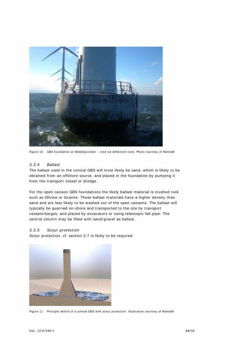
Figure 10 GBS foundation at Middelgrunden – note ice deflection cone. Photo courtesy of Rambøll
3.3.4 Ballast The ballast used in the conical GBS will most likely be sand, which is likely to be obtained from an offshore source, and placed in the foundation by pumping it from the transport vessel or dredge. For the open caisson GBS foundations the likely ballast material is crushed rock such as Olivine or Granite. These ballast materials have a higher density than sand and are less likely to be washed out of the open caissons. The ballast will typically be quarried on-shore and transported to the site by transport vessels/barges, and placed by excavators or using telescopic fall-pipe. The central column may be filled with sand/gravel as ballast. 3.3.5 Scour protection Scour protection, cf. section 3.7 is likely to be required.
Figure 11 Principle sketch of a conical GBS with scour protection. Illustration courtesy of Rambøll

Dok. 13/97289-2 25/58
Table 12 shows a rough estimate of quantities. Basis for the estimate is the diameter of the scour protection being from approx. 14 m wider than the GBS base diameter to up to 3 x the diameter, and an average combined layer thickness of up to 1.5 m. The required scour protection will be highly dependent on the design and the actual geotechnical conditions. The quantities estimated do not include filling up scour holes already developed or installation tolerances.
Table 12 Estimates of GBS scour protection
GRAVITY BASE Turbine capacity 3.0 MW 3.6 MW 4.0 MW 8.0 MW 10.0 MW GBS base diameter, m 18–24 20–25 20–25 25–35 30–40 Scour protection diameter1, m
32–74 34–75 34–75 39–100 42–120
Scour protection volume per foundation1, m3
800–4,500 900-4,500 900 4,500 1,200-8,000
1,400-11,000
Total scour protection volume at 66/55/50/25/20 turbines, m3
40,000-297,000
39,000-248,000
35,000-225,000
25,000-200,000
22,000-220,000
Total footprint at 66/55/50/25/20 turbines, m2
53,000-284,000
50,000-237,000
45,000-215,000
30,000-198,000
28,000-226,000
1 Depending on design and the actual geotechnical conditions
If the GBS is placed in a two m deep excavation the diameter of the scour protection is limited to the excavation which effectively will be a diameter in the area of 10 limited and limited to this size. This will reduce the amount of scour protection compared with the values in Table 12. Thus, the values in Table 12 should be considered conservative. 3.3.6 GBS installation The installation of the concrete gravity base will likely take place using a floating crane or crane barge with attendant tugs and support craft. The bases will either be floated or semi-floated (partially submerged supported by the crane) transported to site on a flat-top barge or a semi-submergible barge. The Structures will then be lowered onto the prepared stone bed and filled with ballast. Then the foundation pit is backfilled, and scour protection is installed.
Dok. 13/97289-2 26/58
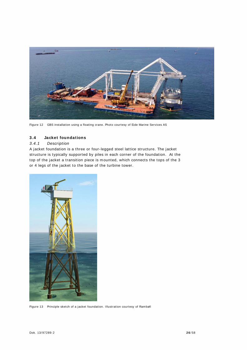
Figure 12 GBS installation using a floating crane. Photo courtesy of Eide Marine Services AS
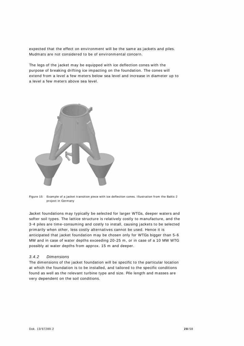
3.4 Jacket foundations 3.4.1 Description A jacket foundation is a three or four-legged steel lattice structure. The jacket structure is typically supported by piles in each corner of the foundation. At the top of the jacket a transition piece is mounted, which connects the tops of the 3 or 4 legs of the jacket to the base of the turbine tower.
Figure 13 Principle sketch of a jacket foundation. Illustration courtesy of Rambøll

Dok. 13/97289-2 27/58
The geometry of the jacket depends on the turbine size and type, the water depth, wave climate, ice climate and soil conditions. The height of the foundation to the turbine interface is typically defined to be sufficiently high to not allow the waves to impact on the transition piece or access platform. Connecting the jacket to the piles, and installing the piles can be done in several ways:
Pre-piling by use of a piling template Piling through pile sleeves attached to the leg bases Pilling inside the legs.
The jacket legs are then attached to the piles by grouting the annulus between the pile and the jacket using a method and type of grout similar to what is described for the monopile/transition piece. If pre-installed piles are not used the jacket may be equipped with mudmats at the base of each leg. Mudmats are flat feet-like attachments, which temporarily supports the jacket and prevents it from sinking into soft seabed, prior and during the installation of the piles in the skirts or through the legs. After the piles are installed and the grouting securing the jacket to them has cured, the mudmats no longer supports the jacket and they are essentially redundant.
Figure 14 Jacket structures on transport barge. Note pile skirts at the base of the legs. Photo courtesy of RWE.
The size of the mudmats depends on the weight of the jacket, the soil load bearing and the environmental conditions. As mudmats are steel structures it is
Dok. 13/97289-2 28/58
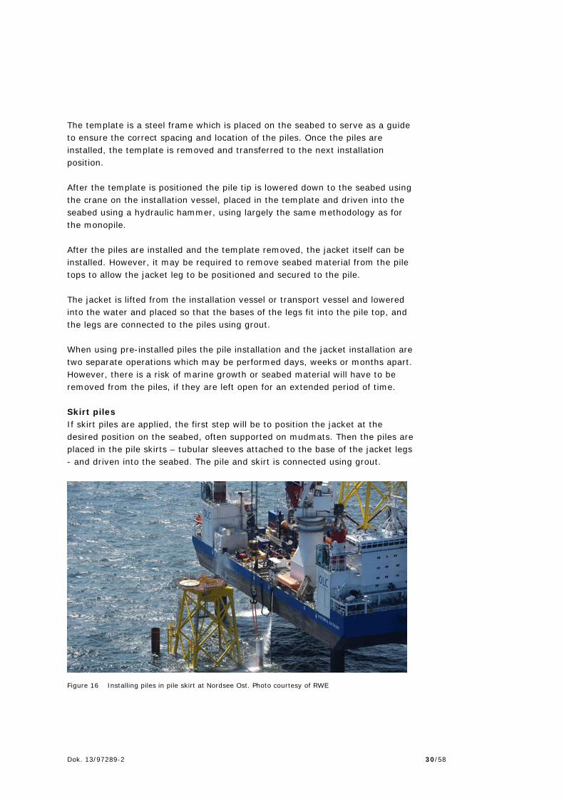
expected that the effect on environment will be the same as jackets and piles. Mudmats are not considered to be of environmental concern. The legs of the jacket may be equipped with ice deflection cones with the purpose of breaking drifting ice impacting on the foundation. The cones will extend from a level a few meters below sea level and increase in diameter up to a level a few meters above sea level.
Figure 15 Example of a jacket transition piece with ice deflection cones. Illustration from the Baltic 2 project in Germany
Jacket foundations may typically be selected for larger WTGs, deeper waters and softer soil types. The lattice structure is relatively costly to manufacture, and the 3-4 piles are time-consuming and costly to install, causing jackets to be selected primarily when other, less costly alternatives cannot be used. Hence it is anticipated that jacket foundation may be chosen only for WTGs bigger than 5-6 MW and in case of water depths exceeding 20-25 m, or in case of a 10 MW WTG possibly at water depths from approx. 15 m and deeper. 3.4.2 Dimensions The dimensions of the jacket foundation will be specific to the particular location at which the foundation is to be installed, and tailored to the specific conditions found as well as the relevant turbine type and size. Pile length and masses are very dependent on the soil conditions.

Dok. 13/97289-2 29/58
Table 13 Estimates of jacket dimensions and masses
JACKET Turbine capacity 3.0 MW 3.6 MW 4.0 MW 8.0 MW 10.0
MW1 Mass, jacket + transition piece, t
250 350 - 1.000 1.100
Mass, 4 piles, t 150 200 - 500 600 Distance between legs at seabed
15x15-18x18
17x17-20x20
18x18-22x22
25x25-30x30
32x32-40x40
Pile length, m 30-50 30-50 30-50 35-60 40-70 Diameter of pile 950-
1,500 950-1,500
1,050-1,600
1,150-1,700
1,200-1,800
Scour protection volume per foundation, m3
800-900 1,000-1,100
1,200-1,300
1,800-1,900
2,500-2,600
Foot print per foundation, m2 700-800 800-900 900-1,000
1,300-1,400
1,600-1,700
Total scour protection volume at 66/55/50/25/20 turbines, m3
53,000-60,000
55,000-61,000
60,000-65,000
45,000-48,000
50,000-52,000
Total footprint at 66/55/50/25/20 turbines, m2
46,000-53,000
55,000-61,000
45,000-50,000
33,000-35,000
32,000-34,000
1 Very rough quantity estimates
3.4.3 Scour protection The formation of local scour around the individual piles is dependent on the pile diameter. As jacket piles typically have a relatively modest diameter, the scour formation is typically also relatively modest, especially when seen in relation to the often rather long jacket pile; it is often accounted for in the design of the piles and jacket. However, the presence of a pile group and a jacket may also cause scour, which may also be relevant to consider. 3.4.4 Seabed preparation Seabed preparation is typically not required for jacket foundations. However, some circumstances, such as mobile sand dunes or the presence of multiple larger boulders, may make it necessary. Dredging can be done by using a suction-type dredge, backhoe/dipper or other type of dredging equipment. The dredged material can be transported away from the actual offshore site by a vessel or barge for deposit. Some sediment spill may be expected during these operations. 3.4.5 Installation The installation of a jacket foundation and piles may be approached in several different ways and depends on, amongst other issues, whether pre-installed piles are used or if skirt piles or through-the-leg piles are applied. Pre-installed piles If pre-installed piles are used, the first step involves the installation of the piles. As the piles must be located within tight tolerances to allow the jacket legs to fit into the piles, a piling template will typically be required. Jacket piles are typically significantly smaller in diameter than the monopiles, but penetrates deeper into the seabed.
Dok. 13/97289-2 30/58
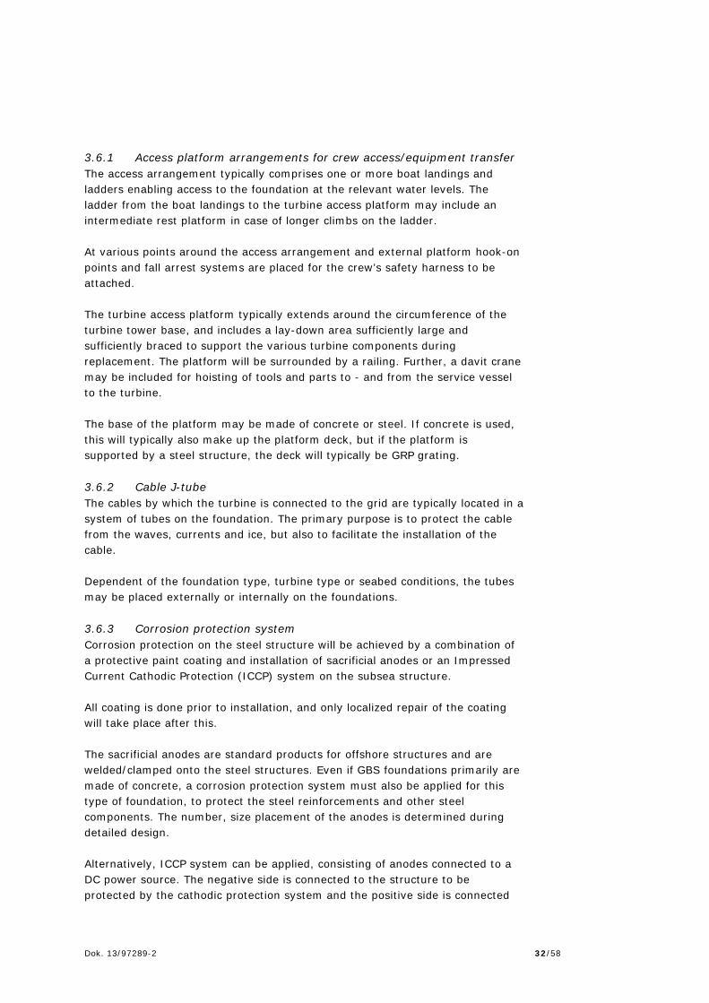
The template is a steel frame which is placed on the seabed to serve as a guide to ensure the correct spacing and location of the piles. Once the piles are installed, the template is removed and transferred to the next installation position. After the template is positioned the pile tip is lowered down to the seabed using the crane on the installation vessel, placed in the template and driven into the seabed using a hydraulic hammer, using largely the same methodology as for the monopile. After the piles are installed and the template removed, the jacket itself can be installed. However, it may be required to remove seabed material from the pile tops to allow the jacket leg to be positioned and secured to the pile. The jacket is lifted from the installation vessel or transport vessel and lowered into the water and placed so that the bases of the legs fit into the pile top, and the legs are connected to the piles using grout. When using pre-installed piles the pile installation and the jacket installation are two separate operations which may be performed days, weeks or months apart. However, there is a risk of marine growth or seabed material will have to be removed from the piles, if they are left open for an extended period of time. Skirt piles If skirt piles are applied, the first step will be to position the jacket at the desired position on the seabed, often supported on mudmats. Then the piles are placed in the pile skirts – tubular sleeves attached to the base of the jacket legs - and driven into the seabed. The pile and skirt is connected using grout.
Figure 16 Installing piles in pile skirt at Nordsee Ost. Photo courtesy of RWE

Dok. 13/97289-2 31/58
Through-the-leg piles The application and installation of through-the–leg piles is similar to the above, except that the jacket legs serve as a guide for the piles instead of the pile skirts, meaning that the piles are inserted at the top of the jacket legs and driven into the seabed. By using a narrow diameter hammer or a pile-follower it is possible to achieve a pile top elevation lower than the top of the jacket legs, thus avoiding a large pile/leg overlap. 3.5 Suction buckets 3.5.1 Description A suction bucket consists of an inverted bucket-like structure. During installation the bucket is placed at the desired position and water trapped inside is pumped out. This creates a vacuum inside the bucket, which combined with the water pressure acting on the outside of the bucket forces the structure to penetrate into the seabed. When the target depth is achieved the bucket is sealed and the installation is largely complete. The basic concept is derived from the suction anchor, which is widely used in the oil & gas industry to secure floating platforms. A suction bucket has been used as foundation for a test WTG near Frederikshavn as well as foundation for offshore metmasts. Further a prototype jacket WTG foundation using suction buckets instead of piles is scheduled for installation in the near future (late 2014/early 2015). A suction bucket is strictly speaking not by itself a foundation solution, but part of a foundation solution, as it can be used instead of piles to anchor mono-tower (monopile)-type or jacket structure (and potentially also other structural solutions) to the seabed. The considerations regarding water depth and turbine size are as what is mentioned for these two types. An important advantage is that pile driving and pile driving noise is avoided. Suction buckets require pliable and relatively homogeneous soil, without hard layers or boulders. Suction bucket is, in the context of offshore wind WTG applications, at a prototype/testing stage. The test WTG at Frederikshavn is mounted on a suction bucket with an outer diameter (OD) of 12 m and a penetration depth of 6 m. However, as the water depth at the site is very shallow it is difficult to use this as a basis for estimating the sizes and quantities involved for applications under different circumstances and for other turbines. 3.6 Secondary structures The foundations will require the following ancillary features for safety and operational protection of equipment:
Access arrangement including boat landing for crew access/equipment transfer
Cable J-tubes Corrosion protection.
Dok. 13/97289-2 32/58
3.6.1 Access platform arrangements for crew access/equipment transfer The access arrangement typically comprises one or more boat landings and ladders enabling access to the foundation at the relevant water levels. The ladder from the boat landings to the turbine access platform may include an intermediate rest platform in case of longer climbs on the ladder. At various points around the access arrangement and external platform hook-on points and fall arrest systems are placed for the crew’s safety harness to be attached. The turbine access platform typically extends around the circumference of the turbine tower base, and includes a lay-down area sufficiently large and sufficiently braced to support the various turbine components during replacement. The platform will be surrounded by a railing. Further, a davit crane may be included for hoisting of tools and parts to - and from the service vessel to the turbine. The base of the platform may be made of concrete or steel. If concrete is used, this will typically also make up the platform deck, but if the platform is supported by a steel structure, the deck will typically be GRP grating. 3.6.2 Cable J-tube The cables by which the turbine is connected to the grid are typically located in a system of tubes on the foundation. The primary purpose is to protect the cable from the waves, currents and ice, but also to facilitate the installation of the cable. Dependent of the foundation type, turbine type or seabed conditions, the tubes may be placed externally or internally on the foundations. 3.6.3 Corrosion protection system Corrosion protection on the steel structure will be achieved by a combination of a protective paint coating and installation of sacrificial anodes or an Impressed Current Cathodic Protection (ICCP) system on the subsea structure. All coating is done prior to installation, and only localized repair of the coating will take place after this. The sacrificial anodes are standard products for offshore structures and are welded/clamped onto the steel structures. Even if GBS foundations primarily are made of concrete, a corrosion protection system must also be applied for this type of foundation, to protect the steel reinforcements and other steel components. The number, size placement of the anodes is determined during detailed design. Alternatively, ICCP system can be applied, consisting of anodes connected to a DC power source. The negative side is connected to the structure to be protected by the cathodic protection system and the positive side is connected

Dok. 13/97289-2 33/58
to the anodes. ICCP system may provide a somewhat better control of the corrosion protection than the sacrificial anode based system. However, a constant power source is required, which has to be maintained and monitored. Another advantage may be that the anode system will typically be less bulky. 3.6.4 Installation The boat landings, ladders, platforms, J-tubes, anodes/ICCP system may be installed at various stages of the foundation fabrication and installation process. For monopile foundations, all the above may be attached to the transition piece prior to installation on the monopile. Alternatively they may be attached as separate sections and after the pile has been installed. For jacket and GBS foundations the typical solution would be that this is fixed to the foundations prior to installation. 3.7 Scour protection Scour is the term used for the localized removal of sediment from the area around the base of a structures located in moving water. If the seabed is erodible and the flow is sufficiently high a scour hole forms around the structure. Scour or erosion will occur when currents or waves accelerate the water flow around the foundation and the vertical velocity gradient of the flow is transformed into a pressure gradient on the leading edge of the structure. This pressure gradient produces a downward flow that impacts the seabed, forming a vortex which sweeps around and downstream of the foundation, and carries away particulate from the adjacent seabed. Two different design approaches are typically applied to account for this:
To install scour protection around the structure, typically by placing rocks around the foundation. This protects the soil and prevents it from being washed away and it continues to support the foundation
To simply allow the scour hole to form, and to account for it in the design of the foundation by assuming a larger water depth and absence of the top layers of the soil.
The latter approach will generally cause a pile to be longer and heavier. In some cases where the properties of the top soil layer will allow a scour hole to develop, the soil may also have poor load bearing characteristics. In such cases the installation of scour protection will not have much effect on the size of the piles, and can therefore be omitted. The scour protection typically consists of a filter layer of stones followed by an armour layer of larger stones/rocks. For a piled foundation structure the scour protection will typically extend 10-15 m from the pile with a thickness of the filter layer can be anticipated to be in the area of 0.7 – 0.9 m and the armour layer in the area of 0.7 – 1.5 m. For a GBS the scour protection will typically
Dok. 13/97289-2 34/58
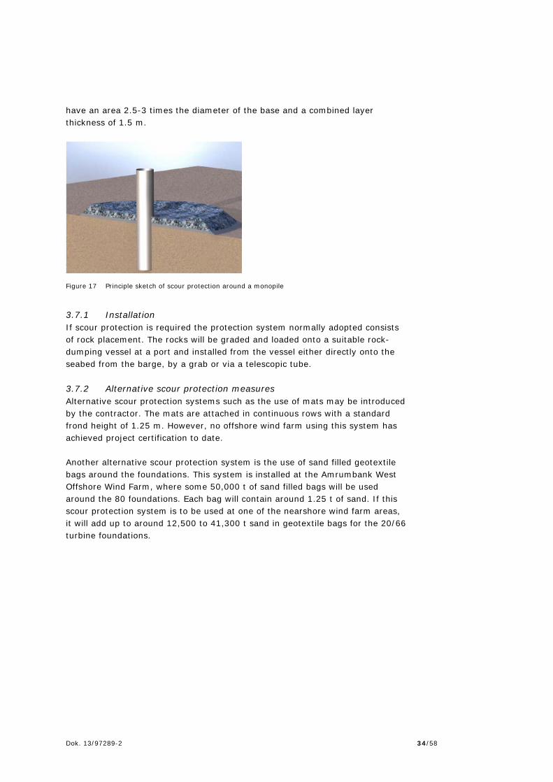
have an area 2.5-3 times the diameter of the base and a combined layer thickness of 1.5 m.
Figure 17 Principle sketch of scour protection around a monopile
3.7.1 Installation If scour protection is required the protection system normally adopted consists of rock placement. The rocks will be graded and loaded onto a suitable rock-dumping vessel at a port and installed from the vessel either directly onto the seabed from the barge, by a grab or via a telescopic tube. 3.7.2 Alternative scour protection measures Alternative scour protection systems such as the use of mats may be introduced by the contractor. The mats are attached in continuous rows with a standard frond height of 1.25 m. However, no offshore wind farm using this system has achieved project certification to date. Another alternative scour protection system is the use of sand filled geotextile bags around the foundations. This system is installed at the Amrumbank West Offshore Wind Farm, where some 50,000 t of sand filled bags will be used around the 80 foundations. Each bag will contain around 1.25 t of sand. If this scour protection system is to be used at one of the nearshore wind farm areas, it will add up to around 12,500 to 41,300 t sand in geotextile bags for the 20/66 turbine foundations.

Dok. 13/97289-2 35/58
4. Cables/grid connection 4.1 Cables and general aspects Medium voltage inter-array submarine cables are expected to be connected to each of the wind turbines and for each row of 5-10 wind turbines depending on the size of the wind turbines. With the basis in 33 kV cables with a conductor cross sectional area of 500 mm2 Cu approx. 36 MW of wind turbines can be connected to each cable. It is expected that the medium voltage submarine cables will run directly onto shore as export cables, and that an offshore step-up transformer is not required. This solution requires that several cables are drawn between the wind farm and the shore. It is expected, that inter-array cables and export cables connecting the wind farm to land possibly could be of higher voltage than stated above when the nearshore wind farm projects are to be constructed since application of higher voltage cables in offshore windmills are under development. Cables of 50 kV at Smålandsfarvandet Havmøllepark and Sejerø Bugt Havmøllepark and cables of 60 kV at Sæby, Vesterhav Syd, Vesterhav Nord and Bornholm could be relevant. Using cables of higher voltage would mean need of fewer parallel export cables to connect the wind farm to land. The distance between the cables leading from the wind farm to shore should be no less than 50 m and up to approx. 100 m if space allows. The larger distance will reduce the risk of disconnecting the entire wind farm if all cables are damaged simultaneously by e.g. a dragging anchor. If certain complicated conditions occur i.e. when passing protected marine areas or other significant areas of interest the distance between cables can on shorter distances be as narrow as 25 m. This will though complicate later service on the cables. When installing cables in protected marine areas supporting reef structures and other protected types of marine habitat detailed routing of the cable will be conducted with the aim of minimizing conflict with those protected habitats as much as possible to avoid or minimize adverse effects on the marine environment. Under such circumstances the detailed routing of the cable will preferably avoid larger structures as stones. But if necessary stones can physically be moved a few meters away from the cable route to allow installation. The disturbance of the protected marine area will thus be of limited significance in time and space and will not remove important structures away from the protected habitat. The detailed routing of the cable will be based on the EIA detailed mapping of marine habitats and the geophysical mapping of the sea bottom surface structure. 4.2 Installation of Cables The submarine cables are transported to the site after cable loading in the load-out harbour. The cables will be placed on turn-tables on the cable laying vessel. The cable laying vessel may rely on tugs for propulsion or can be self-propelled.

Dok. 13/97289-2 36/58
Figure 18 Cable in turn table aboard cable laying vessel. Photo courtesy of Rambøll
All the submarine cables, both array and export cables will be buried to provide protection from fishing activity, dragging of anchors etc. Depending on the seabed condition the cable will be jetted, ploughed, installed in a pre-excavated trench or rock covered for protection. A burial depth of approx. 1-1.5 m must be expected. The final depth will vary depending on a more detailed soil condition survey, incl. geophysical survey (Rambøll, 2014a) and the equipment selected. 4.3 Cable burial by Jetting Water jetting is a cable burial method in which a device (usually a remote operating vessel (ROV)) equipped with water jets fed by high power water pumps liquefy the sediment below the cable, allowing it to sink to a specified depth (dependent on the penetrating length of the swords), after which coarse sediments are deposited. Cable jetting can typically be used in soils such as silt, sand or peat. Water jetting has become an extensively used power cable burial method. Typically, the submarine cable is buried after having been deployed on the seabed. The method is also often used to rebury repaired sections or old cables.

Dok. 13/97289-2 37/58
Post-lay burial has the advantage that cable laying operations are not delayed if difficult burial conditions are encountered. It is an effective method where a thick layer of soft sediments (silt) and/or sand are found in the seabed. There are different types and sizes of jetting equipment. Some small water jetting machines usually have surface water pumps and need assistance from divers and they are typically used in shallow waters. Larger jetting machines with on-board water pumps are often remote-controlled and are capable of operating in deep waters. The effectiveness of the cable protection depends not only on burial depth, but also on the amount of material that will be removed from the trench. The best protection is obtained if the trench is narrow and is filled with the original material immediately after the jetting operation. In some areas an open trench will be filled in a few days or weeks because of the natural current and tide and the transport of material in the waters. It is important to avoid a situation where the cable is jetted down to, typically, 1 m but is lying in a wide open trench without any protection because all material near the cable has been jetted away from the cable. The width of the seabed affected by the jetting operation itself will be approx. 0.7-1.2 m depending on the size of cable and the jetting equipment used. The rate of progress, of the jetting operation, is depending on the seabed encountered. Generally a progress of 500-2,000 m/day may be anticipated. 4.4 Cable burial by plough Another cable installation method is by direct burial of the cable into the seabed. The cable is guided into a self-closing furrow cut by a sea plough towed by a surface vessel. This method requires homogeneous and softer soil conditions. As a cable approaches the seabed, it is fed through the plough, which inserts the cable into a narrow furrow. Different plough designs are available to suit various bottom conditions, e.g. the traditional plough-share is well suited for muddy substrates, whereas sandy sediments may require a plough equipped with water jets to cut a trench into which the cable is placed, thus reducing the needed mechanical power. As a plough passes across the seabed, the share opens a furrow, inserts the cable and allows sediment to fall back, thereby filling the fissure. The precise nature of this disturbance will vary with substrate type, depth of burial and plough type. However, burial in more consolidated substrates may result in only partial closure of the furrow, with displaced sediment deposited at the furrow margins, which can be up to several tenths of cm high. Ploughs are often used for burial of telecom cables and light weight power cables. It is also possible to use a large plough to bury and protect larger power cables, but this method entails some risks if is not both designed and handled with great care. If the plough is not suitable or if it is not operated correctly,

Dok. 13/97289-2 38/58
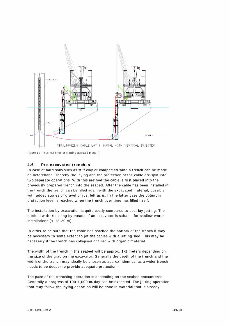
there is a risk to damage the cable it is supposed to protect. Especially if the seabed soil is inhomogeneous, or if the plough hits boulders, logs or other large embedded objects, the plough can lurch, make a sudden sideway move and perhaps damage the cable. The width of the seabed affected by the ploughing operation itself will be in approx. 1-2 meters depending on the size of cable and the equipment used. The pace of the ploughing operation is depending on the seabed encountered and the exact equipment used. Generally a progress of 100-2,000 m/day may be anticipated. 4.5 Vertical injector The vertical injector (jetting assisted plough) consists of a jetting head / sword with water nozzles on the leading edge. The cable is routed through the jetting head and thus the laying and protection is done in one operation. The method is widely used in Asia and in some European countries. The method is well suited for deep installations in jet-able soils, where water depth is relatively shallow. However, the method is very time consuming and to some extent vulnerable to changes in weather. However, in case of severe weather the jetting head can be left in the seabed while the cable ship or barge is on weather stand-by. The method is very suitable for deep installations of cable near shipping lanes and in harbours as the cables can be buried very deep. The width of the seabed affected by the vertical injector installation and the rate of progress may be expected to be the same as the general ploughing operation mentioned earlier, i.e. 1-2 m width, 100-2,000 m/day progress.
Dok. 13/97289-2 39/58
Figure 19 Vertical injector (jetting assisted plough)
4.6 Pre-excavated trenches In case of hard soils such as stiff clay or compacted sand a trench can be made on beforehand. Thereby the laying and the protection of the cable are split into two separate operations. With this method the cable is first placed into the previously prepared trench into the seabed. After the cable has been installed in the trench the trench can be filled again with the excavated material, possibly with added stones or gravel or just left as is. In the latter case the optimum protection level is reached when the trench over time has filled itself. The installation by excavation is quite costly compared to post lay jetting. The method with trenching by means of an excavator is suitable for shallow water installations (< 18-20 m). In order to be sure that the cable has reached the bottom of the trench it may be necessary to some extent to jet the cables with a jetting sled. This may be necessary if the trench has collapsed or filled with organic material. The width of the trench in the seabed will be approx. 1-2 meters depending on the size of the grab on the excavator. Generally the depth of the trench and the width of the trench may ideally be chosen as approx. identical as a wider trench needs to be deeper to provide adequate protection. The pace of the trenching operation is depending on the seabed encountered. Generally a progress of 100-1,000 m/day can be expected. The jetting operation that may follow the laying operation will be done in material that is already

Dok. 13/97289-2 40/58
disturbed by the trenching and the rate of progress may be of 2,000-3,000 m/day. 4.7 Protection by rock cover Rock cover as protection method consists of covering the cable with regular rocks forming a properly designed berm. This application is widely used for submarine pipes. Depth, wave action, sea current, rock size, berm side slope and height are the most important variables to design appropriate cable protection with rock cover. Rock sizes normally utilized vary from 10 to 40 cm, depending on the application. Typically an over-the-side rock dumping vessels will be used. The rock is pushed overboard at a steady pace. This rock dumping method is typically used in shallow water. For deeper water a telescopic fall-pipe may be used. The width of the rock cover can be expected to be 2-3 m. The rate of progress of the operation will depend to great extent on the method used for covering the cables. A progress of 100-1,000 m/day may be anticipated.

Dok. 13/97289-2 41/58
5. Noise 5.1 Noise emissions from installation of monopiles The underwater noise generated by pile driving during installation has been measured and assessed during construction of wind farms in Denmark, Sweden and England among other countries. The noise level and emissions will depend, amongst other things, of the pile diameter, seabed conditions and pile driving equipment. An indicative source level of the pile driving operation would be in the range of 220 to 260dB re 1µPa @1metre, cf. Underwater noise prediction methodology (Rambøll, 2014a). In January 2015 a working group founded by Energinet.dk in cooperation with the Danish Energy Agency and the Danish Nature Agency published a memorandum including method guidelines for handling the regulation of underwater noise in the context of mitigating possible adverse effects on marine mammals (Energinet.dk 2015). The guidelines demand the use of pinger and seal scarer to be an integrated part of construction methods when installing mono piles as foundations for offshore windmills. Hence the use of pinger and seal scarer is a mandatory part of mono pile installation when the nearshore windfarms goes to tender. The guidelines also include the demands of the construction contractor to perform actual measurements to document that they adhere to regulations and conditions given in the permission based on the guidelines (Energinet.dk 2015). The guidelines and method also include the possibility of adjusting effects of underwater noise on marine mammals by regulation of soft start procedures and hammer energy use during piling. When documented necessary the guidelines and method also prescribe how to calculate the need of underwater noise reduction and the subsequent implementation of mitigation measures such as use of bubble curtains etc. In relation to airborne noise emissions, the most extensive noise is also generated from installation of monopiles. A typical range that can be expected from piling at the source level, is normally within a range of LWA: 125-150 dB(A) LWA re 1pW, cf. Airborne noise and vibrations, methods and assumptions (Rambøll, 2014b). The driving of the significantly smaller jacket piles will usually generate less noise. Noise emissions during installation of concrete gravity foundations are considered to be small. 5.2 Operational airborne noise emissions There are two types of noise associated with operation of wind turbines; aerodynamic and mechanical noise. Aerodynamic noise is broad-band in nature, relatively unobtrusive and is strongly influenced by incident conditions, wind speed and turbulence intensity. An operational Sound Power Level at the source is expected in the order of 105 dB(A) to 113dB(A), depending on the selected turbine type and the wind speed.

Dok. 13/97289-2 42/58
Mechanical noise is generated by components inside the turbine nacelle and can be radiated by the shell of the nacelle, blades and the tower structure. Such noise emissions are not considered significant for the present generation of turbines to be considered for the nearshore wind farms. Noise levels on land during the operation of the wind farm are expected to be below allowed limits. The overall limits for operational noise on land according to the Danish legislation are:
44 dB for outdoor areas in relation to neighbours (up to 15 m away) in the open land, and
39 dB for outdoor areas in residential areas and other noise sensitive areas. (Both measured at 8 m/s. If measured at 6 m/s, the limits are 2 dB lower)
For low frequency noise (10 – 6,160 Hz) the limit is 20 dB (A) measured indoor in residential buildings.
Some mechanical noise may be generated from equipment on the platform (transformers, diesel generators etc.) These noise contributions are not deemed significant for the overall noise emissions from the offshore wind farm.
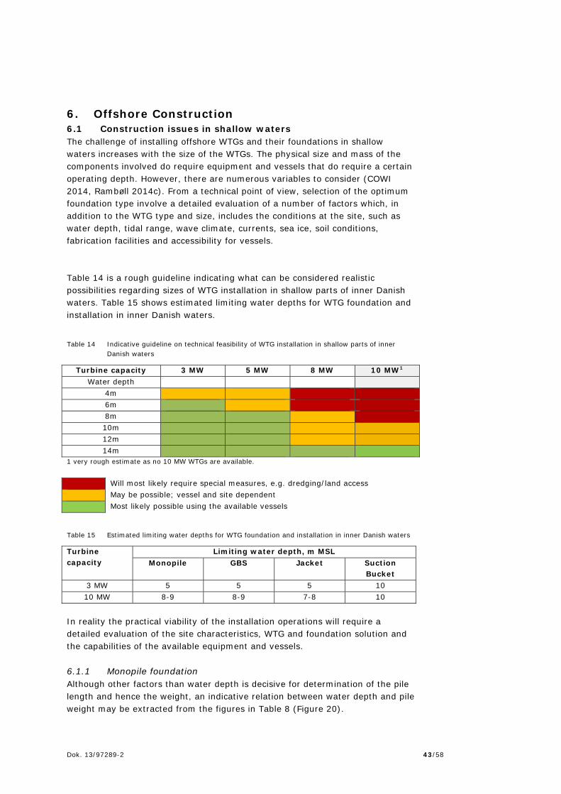
Dok. 13/97289-2 43/58
6. Offshore Construction 6.1 Construction issues in shallow waters The challenge of installing offshore WTGs and their foundations in shallow waters increases with the size of the WTGs. The physical size and mass of the components involved do require equipment and vessels that do require a certain operating depth. However, there are numerous variables to consider (COWI 2014, Rambøll 2014c). From a technical point of view, selection of the optimum foundation type involve a detailed evaluation of a number of factors which, in addition to the WTG type and size, includes the conditions at the site, such as water depth, tidal range, wave climate, currents, sea ice, soil conditions, fabrication facilities and accessibility for vessels. Table 14 is a rough guideline indicating what can be considered realistic possibilities regarding sizes of WTG installation in shallow parts of inner Danish waters. Table 15 shows estimated limiting water depths for WTG foundation and installation in inner Danish waters.
Table 14 Indicative guideline on technical feasibility of WTG installation in shallow parts of inner Danish waters
Turbine capacity 3 MW 5 MW 8 MW 10 MW1 Water depth
4m 6m 8m 10m 12m 14m
1 very rough estimate as no 10 MW WTGs are available. Will most likely require special measures, e.g. dredging/land access May be possible; vessel and site dependent Most likely possible using the available vessels
Table 15 Estimated limiting water depths for WTG foundation and installation in inner Danish waters
Turbine capacity
Limiting water depth, m MSL Monopile GBS Jacket Suction
Bucket 3 MW 5 5 5 10 10 MW 8-9 8-9 7-8 10
In reality the practical viability of the installation operations will require a detailed evaluation of the site characteristics, WTG and foundation solution and the capabilities of the available equipment and vessels. 6.1.1 Monopile foundation Although other factors than water depth is decisive for determination of the pile length and hence the weight, an indicative relation between water depth and pile weight may be extracted from the figures in Table 8 (Figure 20).

Dok. 13/97289-2 44/58
Figure 20 Indicative relation between water depth and monopile weight (COWI 2014)
Considering the normal high tide of 3.5-5 m in the UK waters, experience from that area suggests that water depths of 5 m MSL (corresponding to approx. 4 m at extreme low tide in the inner Danish waters) may be considered a boundary for monopile installation in the 3-4 MW turbine range. For a 10 MW turbine range, foundations of 600 – 1,250 t weight will probably have to be installed by large vessels having a maximum draft of approx. 6m. Allowing for 1 m extreme low tide, 1m under-keel clearance, and an addition 1 m for uncertainty of weight estimates, a water depth of 8-9 m MSL may be considered a boundary for monopile installation of the 10 MW turbine range in the inner Danish waters. 6.1.2 Gravity base structure (GBS) With the same assumptions as for monopiles, the indicative relationship between GBS weight and water depth has been stipulated based on the figures in Table 11 (Figure 21). The weight estimate for an 8 MW turbine GBS foundation appears to fall outside the trend found for the other turbine sizes. However, it falls within the minimum and the maximum foundation weights for the water depths in concern and will therefore be of no consequence for the delimitation of a worst case scenario for assessment of environmental impacts.

Dok. 13/97289-2 45/58
Figure 21 Indicative relation between water depth and weight of GBS foundation (COWI 2014)
Relevant experiences on water depth boundaries for GBS foundations are limited to Nysted, Rødsand 2 and Lillgrund which all have 2.3 MW WTGs installed with the use of a vessel with a max. draft of 3.6 m. At Nysted/Rødsand a minimum water depth of 5.75 m MSL is found, and at Lillegrund a minimum design seabed level of 4.7m is indicated, in both cases with foundation weights of about 1,200 t (COWI 2014) similar to the estimated weights of a GBS foundation for a 3 MW turbine. This suggests that a minimum water depth of about 5 m MSL will be required for the 3 MW turbine range. Table 11 estimates a GBS foundation weight of a 10 MW turbine at 3,000 t. Given the uncertainty involved, a weight range of 3,000-4,000 t is considered an appropriate estimate in relation to GBS foundation installation in shallow waters. Vessels exist which have the necessary lifting capacity, a few of which have maximum drafts as low as 4.5 and 4.9 m. They would require a minimum water depth of 7-8 m with due allowance for extreme low tide, under-keel clearance and uncertainties. 6.1.3 Jacket foundation Very little experience exists with jacket foundations in shallow waters. No weight estimations for jacket foundation are given in Chapter 3. A range of approx. 500 – 1,500 to for the jacket structure may be assumed, and pile weights would be in the order of 50 – 200 t for pile lengths given in Table 13 (COWI 2014). As discussed in section 3.4 it is not very likely that jacket foundations are cost-effective in shallow waters.

Dok. 13/97289-2 46/58
However, with an assumed weight of 500 t for a jacket for a 3 MW turbine, installation vessels are available allowing for installation at 5 m water depth. For an assumed weight of 1,500 to for a jacket for a 10 MW turbine a minimum depth of 7-8 m will be required like for a GBS foundation. 6.1.4 Suction bucket Although it has not possible to provide dimensions estimates for suction buckets, a few salient features pertinent to limiting water depths are suggested (COWI 2014):
A minimum of 10 m water depth appears to be required to get sufficient water column to provide the required downward force
Foundation weights may be roughly estimated at 400 – 800 to for 3 MW – 10 MW turbines at 25 m water depth.
Hence, the required minimum water depth for suction buckets appears to be determined by requirements for sufficient water column pressure rather land installation vessel limitations. With a minimum of 10 m water depth quite a number of vessels are available with capacities in the range of 400 – 800 t foundation weights. 6.2 Access to site and safety zones The construction of the proposed wind farm is scheduled to take place throughout the year. Construction activity is expected for 24 hours per day 7 days a week until construction is complete. A safety zone of 500m is expected to be established around the main construction sites in order to protect the project, personnel, and for the safety of third parties during the construction and commissioning phases of the wind farm. The safety zone may include the entire construction area or a rolling safety zone may be selected. The exact safety zone will be agreed with the Danish Maritime Authority (DMA) prior to construction. It is intended that third parties will be excluded from any safety zone during the construction period, and that the zone(s) will be marked in accordance with the requirements from the DMA, cf. section 6.4. To optimise the construction program, it is likely that installation of wind turbines, foundations and cables will be undertaken on the site at the same time, although not necessarily within the same part of the site. Therefore it is likely that approx. 10-15 vessels (including support vessels) may be on site at any time during the construction phase. 6.3 Helicopter Helicopters may also to a certain extend be used in the construction works. However, as the WTGs are located near the shore, the main advantage of the use of helicopters – high speed/ability to cover large distances quickly giving a
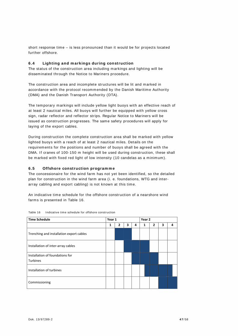
Dok. 13/97289-2 47/58
short response time – is less pronounced than it would be for projects located further offshore. 6.4 Lighting and markings during construction The status of the construction area including markings and lighting will be disseminated through the Notice to Mariners procedure. The construction area and incomplete structures will be lit and marked in accordance with the protocol recommended by the Danish Maritime Authority (DMA) and the Danish Transport Authority (DTA). The temporary markings will include yellow light buoys with an effective reach of at least 2 nautical miles. All buoys will further be equipped with yellow cross sign, radar reflector and reflector strips. Regular Notice to Mariners will be issued as construction progresses. The same safety procedures will apply for laying of the export cables. During construction the complete construction area shall be marked with yellow lighted buoys with a reach of at least 2 nautical miles. Details on the requirements for the positions and number of buoys shall be agreed with the DMA. If cranes of 100-150 m height will be used during construction, these shall be marked with fixed red light of low intensity (10 candelas as a minimum). 6.5 Offshore construction programme The concessionaire for the wind farm has not yet been identified, so the detailed plan for construction in the wind farm area (i. e. foundations, WTG and inter-array cabling and export cabling) is not known at this time. An indicative time schedule for the offshore construction of a nearshore wind farms is presented in Table 16.
Table 16 Indicative time schedule for offshore construction
Time Schedule Year 1 Year 2
1 2 3 4 1 2 3 4
Trenching and installation export cables
Installation of inter‐array cables
Installation of foundations for
Turbines
Installation of turbines
Commissioning

Dok. 13/97289-2 48/58
The offshore installation work is very weather dependent. It is often possible to perform the installation throughout the year, but the risk of adverse weather conditions preventing operations is higher during the winter months. The most weather sensitive operation is expected to be the turbine installation, and it must be expected that a construction schedule allowing this to be done in the typically calmer weather mid-year will be preferred. 6.6 Emissions and discharges During construction (and decommissioning) some emissions to the atmosphere will be emitted from the vessels and helicopters (if relevant) working on the EIA, surveys, investigations, construction, operation and decommissioning phases. These emissions are not considered to be significant. Differences in vessel traffic and emission due to various cable laying methods are negligible compared to the total shipping traffic and emission when building a wind farm. In addition, there is a minor risk of accidental discharges or spill from the turbines or marine vessels associated with construction and decommissioning. No oil must be discharges intentionally in Danish territorial waters according to the Danish Regulation no. 174 of 25/02/2014 on discharge of oil from marine vessels. There are not anticipated solid discharges into the marine environment during the construction phase. All waste generated during construction will be collected and disposed of by licensed waste management contractors to licensed waste management facilities onshore. It will be required that the vessels working during construction and also operation and decommissioning must comply with Act no. 963 of 03/07/2013 on protection of the marine environment (havmiljøloven). 6.7 Access to site and safety zones during service life Safety zones can be applied for the wind farm area or parts hereof. The specific safety zones will be determined by the Danish Maritime Authority (DMA). A 200 m safety zone around all cables will be expected. The safety zone of 200m on either side of the cables will normally include restriction for anchoring and e.g. bottom trawling that may be intrusive into the seabed. The project needs to comply with Regulation no. 939 of 27/11/1992 on protection of sea cables and submarine pipes specifying these protection zones and agree with the DMA on the extent of potential safety zones. During operation safety zones of 200 m on each side of both inter-array cables and transport cables is expected to be established. This zone will also include windmill foundations. In the safety zone anchoring and trawling will be prohibited. For the actual project the decisions on prohibited entry zones will be made by the DMA.

Dok. 13/97289-2 49/58
7. Operation and maintenance Operation and maintenance of the offshore wind farms will continue 24 hours per day, 365 days per year, and access to site may be required at any time. The harbours to be used during construction and maintenance have not yet been identified. The wind farm will be serviced and maintained throughout the life of the wind farm from a local port in the vicinity of the wind farm. Following the commissioning period of the wind farm, it is expected that the scheduled inspection and servicing interval for the turbines will be approximately 6 months. Maintenance schedules of the wind farm depend on the turbine type installed, but is normally separated into two different categories:
1. Scheduled inspection/maintenance 2. Periodic overhauls 3. Un-scheduled maintenance.
7.1 Scheduled inspection/maintenance Scheduled inspection/maintenance involves primarily inspection and replacement of wear parts, check of lubrication and other fluids and filters. A scheduled inspection of each turbine is likely to take place every six months. Scheduled maintenance will be performed using service vessels operated from the local harbour. Inspections of support structures and subsea cables will be performed on a regular basis as well as ad-hoc visits for surveillance purposes, e.g. following a storm. 7.2 Periodic overhauls Periodic overhauls will be carried out in accordance with the turbine manufacturer’s recommendations. These overhaul campaigns will be planned for execution in the periods of the year with the best access conditions, preferably in summer. The periodic overhauls will be carried out according to the supplier’s specifications. The work typically includes function and safety tests, visual inspections, analysis of oil samples, change of filters, lubrication, check of bolts, replacement of brake pads, oil change on gear box or hydraulic systems. 7.3 Unscheduled maintenance Unscheduled maintenance involves the correction of any sudden defects. The scope of such maintenance may range from correcting defects or replacing minor components to repairing or replacing failed main components, such as generator, gearbox, transformer, main bearings, rotor blade. The repair or replacement of minor components can be completed using the staff and vessels involved in the regular scheduled maintenance, but if the correction of the defect involves the removal/replacement of one of the main
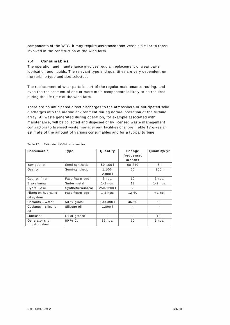
Dok. 13/97289-2 50/58
components of the WTG, it may require assistance from vessels similar to those involved in the construction of the wind farm. 7.4 Consumables The operation and maintenance involves regular replacement of wear parts, lubrication and liquids. The relevant type and quantities are very dependent on the turbine type and size selected. The replacement of wear parts is part of the regular maintenance routing, and even the replacement of one or more main components is likely to be required during the life time of the wind farm. There are no anticipated direct discharges to the atmosphere or anticipated solid discharges into the marine environment during normal operation of the turbine array. All waste generated during operation, for example associated with maintenance, will be collected and disposed of by licensed waste management contractors to licensed waste management facilities onshore. Table 17 gives an estimate of the amount of various consumables and for a typical turbine.
Table 17 Estimate of O&M consumables
Consumable Type Quantity Change frequency,
months
Quantity/yr
Yaw gear oil Semi-synthetic 50-100 l 60-240 6 l Gear oil Semi-synthetic 1,100-
2,000 l 60 300 l
Gear oil filter Paper/cartridge 3 nos. 12 3 nos. Brake lining Sinter metal 1-2 nos. 12 1-2 nos. Hydraulic oil Synthetic/mineral 250-1200 l - Filters on hydraulic oil system
Paper/cartridge 1-3 nos. 12-60 <1 no.
Coolants – water 50 % glucol 100-300 l 36-60 50 l Coolants – silicone oil
Silicone oil 1,800 l - -
Lubricant Oil or grease - - 10 l Generator slip rings/brushes
80 % Cu 12 nos. 60 3 nos.

Dok. 13/97289-2 51/58
8. Decommissioning The life span of the wind farm is estimated at 30 years. It is expected that two years in advance of the expiry of the production time the developer shall submit a decommissioning plan. The method for decommissioning will follow best practice and the legislation at that time. It is unknown at this stage how the wind farm may be decommissioned; this will have to be agreed with the competent authorities before the work is being initiated. It is expected that an EIA statement (VVM-redegørelse) will be required for the decommissioning of the wind farm. The following sections provide a description of the current intentions with respect to decommissioning, with the intention to review the statements over time as industry practices and regulatory controls evolve. 8.1 Extent of decommissioning The objectives of the decommissioning process are to minimise both the short and long term effects on the environment whilst making the sea safe for others to navigate. Based on current available technology, it is anticipated that the following level of decommissioning on the wind farm will be performed:
WTGs – to be removed completely Structures and substructures – to be removed to at or just below the
natural seabed level and below this left in situ Infield cables – to be either removed (in the event they have become
unburied) or to be left safely in situ, buried to below the natural seabed level or protected by rock-dump
Export cables – to be left safely in situ, buried to below the natural sea-bed level or protected by rock-dump
Cable shore landing – to be either safely removed or left in-situ, with particular respect to the natural sediment movement along the shore
Scour protection – to be left in situ. 8.2 Decommissioning an offshore wind farm Decommissioning of wind turbines The wind turbines would be dismantled using similar vessels and methods as deployed during the construction phase. However the operations would be carried out in reverse order. Decommissioning of buried cables Should cables be required to be decommissioned, the cable recovery process would essentially be the reverse of a cable laying operation, with the cable handling equipment working in reverse gear and the cable either being coiled into tanks on the vessel or guillotined into sections approximately 1.5m long immediately as it is recovered. These short sections of cable would then be stored in skips or open containers on board the vessel for later disposal through appropriate routes for material reuse, recycle or disposal.

Dok. 13/97289-2 52/58
Uncovering the cables will cause a disturbance of the seabed and caused sediments to be suspended in the water and dispersed. Decommissioning of foundations Foundations may be decommissioned through partial of complete removal. For monopiles the most likely scenario is that that the foundations will be removed to at or just below the level of the natural seabed. The same is assumed for jacket foundations. The removal of GBS foundations will involve the removal of the ballast before the concrete structures can be lifted from the seabed. It may be required to inject water at high pressure under the foundations to loosen these from the seabed. Alternatively the concrete structures may be demolished in situ and removed in pieces. For gravity foundations it may be that some of these can be left in situ. At the stage of decommissioning natural reef structures may have evolved around the structures and the environmental impact of removal may be such that it is seen as the best solution to leaving the foundations in place. The reuse or removal of foundations must be agreed with the regulators at the time of decommissioning. The suction bucket is expected to be removable by pressurizing the inside of the bucket, forcing the structure out of the seabed, from where it can be lifted out and removed for disposal. Decommissioning of scour protection The scour protection will most likely be left in situ and not be removed as part of the decommissioning. It will not be practically possible to remove all scour protection materials as major parts of it must be expected to have sunk into the seabed. Also it is expected that the scour protection will function as a natural stony reef. The removal of this stony reef is expected to be more damaging to the environment in the area than if left in situ. It is therefore considered most likely that the regulators at the time of decommissioning will accept or require the scour protection to be left in situ. 8.3 Disposal or re-use of components It is likely that legislation and custom will dictate the practices adopted for the decommissioning of the wind farm. The decommissioned materials might have the following disposal methods:
All steel, cast iron, copper and other metal components scrapped and recycled.
The turbine blades (GRP and carbon fibre) as well as GRP grating to be disposed of in accordance with the relevant regulations in force at the time of decommissioning.

Dok. 13/97289-2 53/58
Reuse of concrete from foundations. Crushed concrete is typically used as fill material for civil engineering projects but does represent a low monetary value
All heavy metals and toxic components (likely to be small in total) disposed of in accordance with relevant procedures and regulations.

Dok. 13/97289-2 54/58
9. References COWI 2014, Limiting water depths for installation. Technical Note. Energinet.dk 2014a. Technical Project Description for the large-scale offshore wind farm (400 MW) at Horns Rev 3 Energinet.dk 2014b. Technical Project Description for the large-scale offshore wind farm (600 MW) at Kriegers Flak, draft Energinet.dk 2015. Marine mammals and underwater noise in relation to pile driving – Working Group 2014. Memorandum published January 21th 2015 by Energinet.dk NIRAS 2014. Technical project description for the nearshore wind farms (450 MW). March 2014 Rambøll 2014a. Underwater noise prediction methodology. April 2014 Rambøll 2014b. Metoder og forudsætninger for undersøgelse af luftbåren støj. April 2014 Rambøll 2014c. Construction Issues, Offshore Wind in Shallow Waters. March 2014

Appendix 2: Vesterhav Nord
Offshore Wind Farm – Technical
Description, Offshore

Appendix 2: Vesterhav Nord Offshore Wind Farm – Technical Description, Offshore
Dok. 13/97529-4 2/16
Appendix 2: Vesterhav Nord Offshore Wind Farm – Technical
Description, Offshore
Published by Energinet.dk
Published as Internet version only:
Report no. 13-97529-4
Version no. [xx xx xx xx]
Energinet.dk
Tonne Kjærsvej 65
7000 Fredericia
Tlf. 70 10 22 44
The report may be downloaded the Danish Energy Agency’s (Energistyrelsen)
website:
www.ens.dk
2015
Dok. 13/97529-4 3/16
Energinet.dk
Table of contents
1. Location ......................................................................................... 2
2. Wind farm layout ............................................................................. 4
3. Foundation ..................................................................................... 6 3.1 Monopile .............................................................................. 6 3.2 Gravity base ........................................................................ 7 3.3 Jacket foundation ................................................................. 7 3.4 Installation scenario .............................................................. 8
4. Pre-investigations ............................................................................ 8 4.1 Investigations ...................................................................... 8 4.2 Summary of seabed survey ................................................ 8
5. List of enclosures ............................................................................ 14

Appendix 2: Vesterhav Nord Offshore Wind Farm – Technical Description, Offshore
Dok. 13/97529-4 2/16
1. Location
Vesterhav Nord offshore wind farm (OWF) area is located in the North Sea
approx. 4 km off the coast southwest of the city of Thyborøn. The pre-
investigation area for Vesterhav Nord covers approx. 60 km2 and the water
depth varies between 15 and 25 m. Northwest of the wind farm area there is an
area approved for raw materials extraction. That area cannot be used for
installation of turbines or cables. The existing approval expired 31 December
2013. The pre-investigations include two export cable corridors located in the
OWF area’s southern and middle part, respectively. The survey corridor for the
export cables is 500 m wide. The offshore wind farm area and export cable
corridors are illustrated in Figure 1with bordering coordinates listed in Table 1.

Dok. 13/97529-4 3/16
Energinet.dk

Dok. 13/97529-4 4/16
Energinet.dk
Figure 1 Vesterhav Nord offshore pre-investigation area and cable corridors.
Black numbers represents coordinates for OWF area, red numbers
represents coordinates for export cable corridors.
Table 1 List of coordinates for pre-investigation area and export cable corridors
for Vesterhav Nord Offshore Wind Farm
ETRS 1989 UTM Zone 32N
Export cable corridors
ID EASTING NORTHING
1 443155 6273448
2 447093 6272293
3 441683 6265867
4 445725 6265657
Pre-investigation area for offshore wind farm
1 442278 6270140
2 441967 6268229
3 441727 6266774
4 441650 6265200
5 439930 6265200
6 440034 6280379
7 441796 6283150
8 446100 6283150
9 445165 6280940
10 443717 6276767
11 443644 6275293
2. Wind farm layout
A maximum of 200 MW wind power may be installed at Vesterhav Nord Offshore
Wind Farm. Preliminary layouts for the wind farm have been developed by DTU
Wind Energy for the purpose of serving as worst case scenarios for the
Environmental Impact Assessment (refer to Enclosure 1). Layouts for 3.0 MW
and 10.0 MW WTGs, respectively, are presented in Figure 2. The final layout will
eventually be decided by the developer, based on an optimization of a number
of parameters, within the frame of the consent to be issued by the authorities.
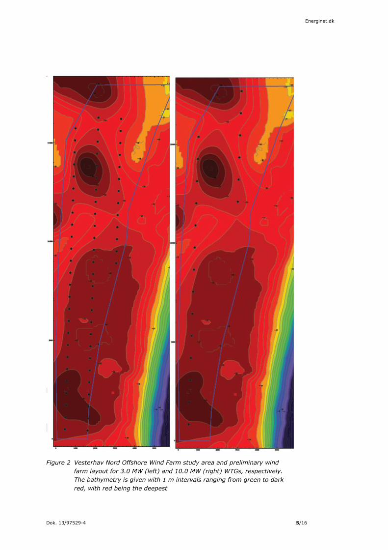
Dok. 13/97529-4 5/16
Energinet.dk
Figure 2 Vesterhav Nord Offshore Wind Farm study area and preliminary wind
farm layout for 3.0 MW (left) and 10.0 MW (right) WTGs, respectively.
The bathymetry is given with 1 m intervals ranging from green to dark
red, with red being the deepest

Dok. 13/97529-4 6/16
Energinet.dk
3. Foundation
Foundation dimensions are given in tables below, based on the general
indicative dimensions given in the generic technical project description. The
quantity estimates should be considered rough as they are not based on site
information on geotechnical conditions and significant wave heights.
Suction bucket foundations are at a prototype/testing stage and dimensions are
uncertain, but they will be smaller than a GBS. For the purpose of environmental
impact assessment they are assumed of smaller dimensions than a GBS.
3.1 Monopile
Table 2 provides estimated dimensions for five different sizes of turbines at
Vesterhav Nord Offshore Wind Farm. The water depth varies between 15 - 25 m.
An average depth of 20 m was used for the calculations.
Table 2 Estimated monopile foundation dimensions
MONOPILE 3.0MW 3.6MW 4.0MW 8.0MW 10.0MW
Outer
Diameter at
seabed
level*
5.0-6.0m 5.0-6.5 m 5.5-7.0 m 6.0-8.0m 7.0-9.5m
Pile Length 45-55m 45-60 m 50-65m 55-70m 60-80m
Pile weight 300-600t 350-700 t 450-800t 700-1,000t 900-1,250t
Ground
Penetration
(below mud
line)
23-30m 23-30m 24-31m 27-34m 29-39m
TRANSITION PIECE
Length 15–20m 15-20m 15–24m 23-30m 23-31m
Outer
Diameter
(based on a
conical
shaped
monopole)
4.0-5.5m 4.0-5.5m 4.5-6.0m 5.5-7.0m 6.0-7.5m
TP weight 160-250t 160-250t 170-260t 220-370t 270-420t
Volume of
Grout per
unit
15-35m³ 15-35m³ 20-40m³ 25-60m³ 30-65m³
SCOUR PROTECTION
Volume per
foundation
(+/-150 m³)
2,100m³ 2,100m³ 2,500m³ 3,000m³ 3,500m³
Foot print
area per
foundation
(+/-100 m2 )
1,500m2 1,500m2 1,600m2 1,650m2 2,000m2
*Outer diameter at and below the seabed level. Above the seabed the diameter normally
decreasse resulting in a conical shape of the monopile.

Dok. 13/97529-4 7/16
Energinet.dk
3.2 Gravity base
Table 3 shows estimated dimensions for five different sizes of turbines at
Vesterhav Nord Offshore Wind Farm. The water depth varies between 15 - 25 m.
An average depth of 20 m has been used for the calculations.
Table 3 Estimated GBS foundation dimensions
GRAVITY BASE 3.0MW 3.6MW 4.0MW 8.0MW 10.0MW*
Shaft Diameter 4.0-5.5m 4.8-6.0m 4.5-6.0m 5.0-6.0 m 6.0-7.0m
Area of Base of
Base
330 -
440m²
360 -
465m²
360 -
465m² 425 - 550m²
450 -
600m²
Concrete weight
per unit
1,400-
2,000t
1,500-
2,200t
1,500-
2,200t 2,500-3,500t
3,000-
4,000t
BALLAST
Type Infill sand Infill sands Infill sands Infill sands Infill sands
Volume per unit
(m3)
800-
1,100m³
1,000-
2,000m³
1,000-
2,000m³
2,000-
2,500m³
2,300-
2,800m³
SCOUR PROTECTION
Size of Excavation
(approx.) 25-28m 23-30m 27-33m 35-45m 40-50m
Material
Excavation (per
base)
1,200-
1,600m³
1,500-
1,800m³
1,500-
1,800m³
1,800-
2,500m³
2,000-
3,200m³
Stone Replaced
into Excavation
(per base) – stone
bed
140-
180m³ 160-200m³
160-
200m³ 200-300m³ 240-400m³
Scour protection
(per base)
800-
1,000m³
900-
1,100m³
900-
1,100m³
1,400-
1,700m³
1,600-
2,000m³
Foot print area
(per base)
1,000-
1,300m²
1,100-
1,400m²
1,100-
1,400m²
1,500-
1,900m²
1,700-
2,600m²
3.3 Jacket foundation
Table 4 shows estimated dimensions for five different sizes of turbines at
Vesterhav Nord Offshore Wind Farm. The water depth varies between 15 - 25 m.
An average depth of 20 m was used for the calculations.
Table 4 Estimated jacket foundation dimensions
Jacket 3.0MW 3.6MW 4.0MW 8.0MW 10.0MW
Distance between
legs at seabed 18 x 18m 20 x 20m 22 x 22m 30 x 30m 40 x 40m
Pile Length 40 – 50m 40 – 50m 40 – 50m 50-60m 60-70m
Diameter of pile 1,200 –
1,500mm
1,200 –
1,500mm
1,300 –
1,600mm
1,400 –
1,700mm
1500 –
1800mm
Scour protection
volume per
foundation
(+/-150 m³)
800m3 1,000m3 1,200m3 1,800m3 2,500m3
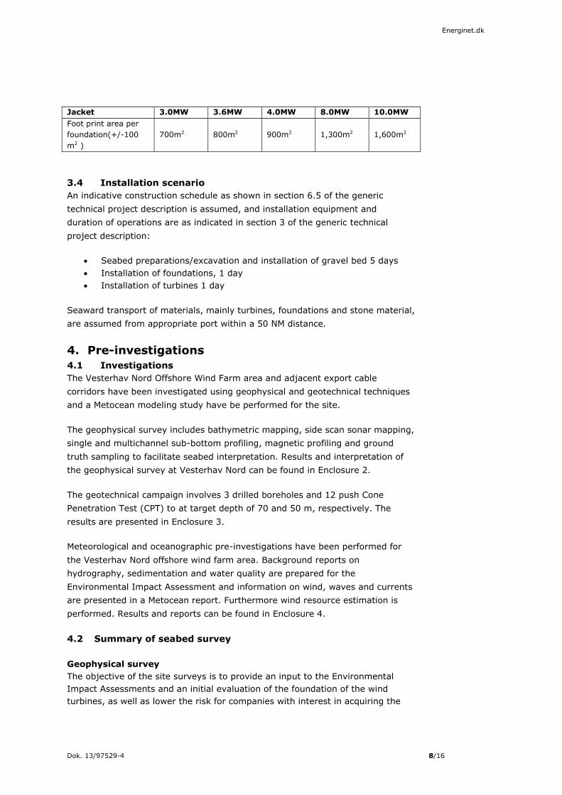
Dok. 13/97529-4 8/16
Energinet.dk
Jacket 3.0MW 3.6MW 4.0MW 8.0MW 10.0MW
Foot print area per
foundation(+/-100
m2 )
700m2 800m2 900m2 1,300m2 1,600m2
3.4 Installation scenario
An indicative construction schedule as shown in section 6.5 of the generic
technical project description is assumed, and installation equipment and
duration of operations are as indicated in section 3 of the generic technical
project description:
Seabed preparations/excavation and installation of gravel bed 5 days
Installation of foundations, 1 day
Installation of turbines 1 day
Seaward transport of materials, mainly turbines, foundations and stone material,
are assumed from appropriate port within a 50 NM distance.
4. Pre-investigations
4.1 Investigations
The Vesterhav Nord Offshore Wind Farm area and adjacent export cable
corridors have been investigated using geophysical and geotechnical techniques
and a Metocean modeling study have be performed for the site.
The geophysical survey includes bathymetric mapping, side scan sonar mapping,
single and multichannel sub-bottom profiling, magnetic profiling and ground
truth sampling to facilitate seabed interpretation. Results and interpretation of
the geophysical survey at Vesterhav Nord can be found in Enclosure 2.
The geotechnical campaign involves 3 drilled boreholes and 12 push Cone
Penetration Test (CPT) to at target depth of 70 and 50 m, respectively. The
results are presented in Enclosure 3.
Meteorological and oceanographic pre-investigations have been performed for
the Vesterhav Nord offshore wind farm area. Background reports on
hydrography, sedimentation and water quality are prepared for the
Environmental Impact Assessment and information on wind, waves and currents
are presented in a Metocean report. Furthermore wind resource estimation is
performed. Results and reports can be found in Enclosure 4.
4.2 Summary of seabed survey
Geophysical survey
The objective of the site surveys is to provide an input to the Environmental
Impact Assessments and an initial evaluation of the foundation of the wind
turbines, as well as lower the risk for companies with interest in acquiring the
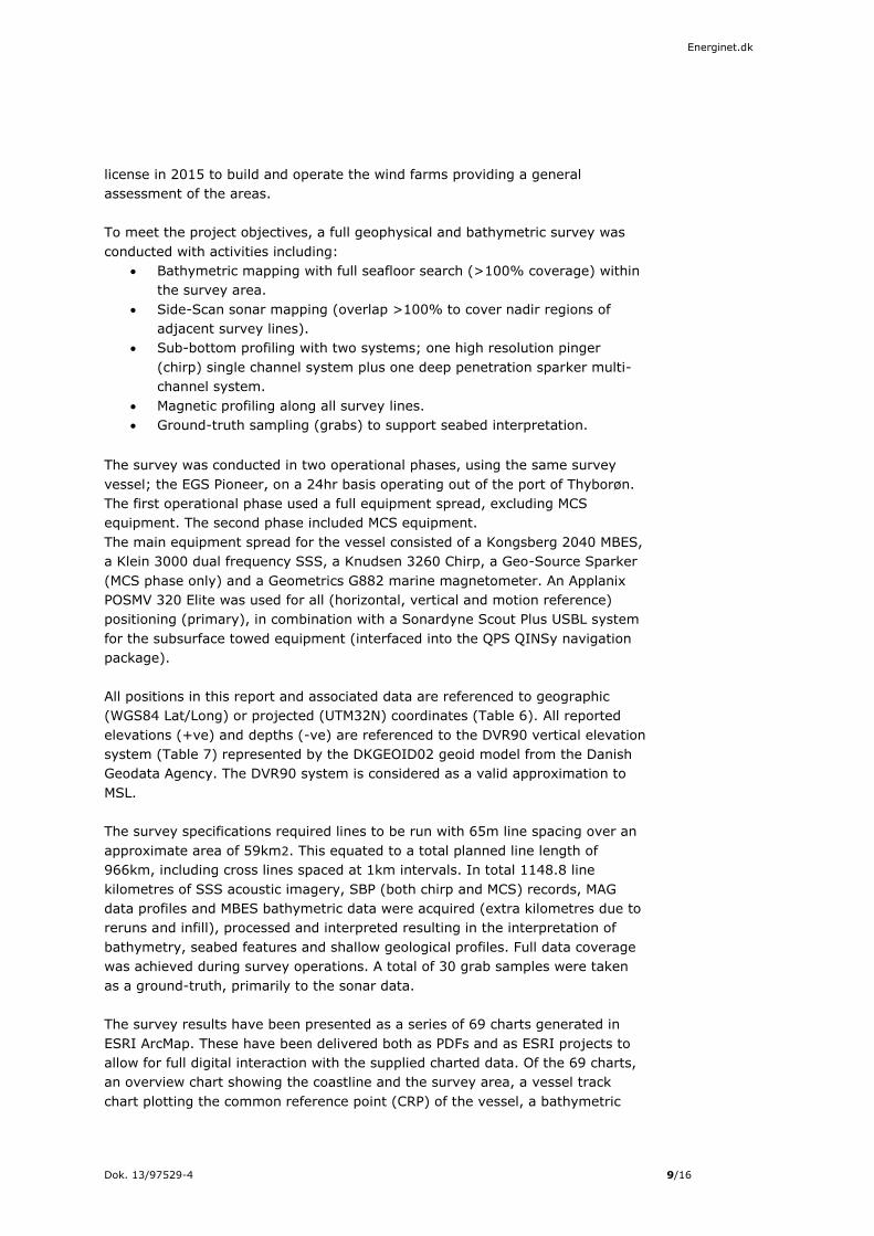
Dok. 13/97529-4 9/16
Energinet.dk
license in 2015 to build and operate the wind farms providing a general
assessment of the areas.
To meet the project objectives, a full geophysical and bathymetric survey was
conducted with activities including:
Bathymetric mapping with full seafloor search (>100% coverage) within
the survey area.
Side-Scan sonar mapping (overlap >100% to cover nadir regions of
adjacent survey lines).
Sub-bottom profiling with two systems; one high resolution pinger
(chirp) single channel system plus one deep penetration sparker multi-
channel system.
Magnetic profiling along all survey lines.
Ground-truth sampling (grabs) to support seabed interpretation.
The survey was conducted in two operational phases, using the same survey
vessel; the EGS Pioneer, on a 24hr basis operating out of the port of Thyborøn.
The first operational phase used a full equipment spread, excluding MCS
equipment. The second phase included MCS equipment.
The main equipment spread for the vessel consisted of a Kongsberg 2040 MBES,
a Klein 3000 dual frequency SSS, a Knudsen 3260 Chirp, a Geo-Source Sparker
(MCS phase only) and a Geometrics G882 marine magnetometer. An Applanix
POSMV 320 Elite was used for all (horizontal, vertical and motion reference)
positioning (primary), in combination with a Sonardyne Scout Plus USBL system
for the subsurface towed equipment (interfaced into the QPS QINSy navigation
package).
All positions in this report and associated data are referenced to geographic
(WGS84 Lat/Long) or projected (UTM32N) coordinates (Table 6). All reported
elevations (+ve) and depths (-ve) are referenced to the DVR90 vertical elevation
system (Table 7) represented by the DKGEOID02 geoid model from the Danish
Geodata Agency. The DVR90 system is considered as a valid approximation to
MSL.
The survey specifications required lines to be run with 65m line spacing over an
approximate area of 59km2. This equated to a total planned line length of
966km, including cross lines spaced at 1km intervals. In total 1148.8 line
kilometres of SSS acoustic imagery, SBP (both chirp and MCS) records, MAG
data profiles and MBES bathymetric data were acquired (extra kilometres due to
reruns and infill), processed and interpreted resulting in the interpretation of
bathymetry, seabed features and shallow geological profiles. Full data coverage
was achieved during survey operations. A total of 30 grab samples were taken
as a ground-truth, primarily to the sonar data.
The survey results have been presented as a series of 69 charts generated in
ESRI ArcMap. These have been delivered both as PDFs and as ESRI projects to
allow for full digital interaction with the supplied charted data. Of the 69 charts,
an overview chart showing the coastline and the survey area, a vessel track
chart plotting the common reference point (CRP) of the vessel, a bathymetric
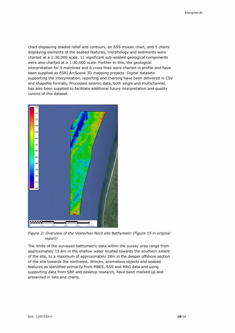
Dok. 13/97529-4 10/16
Energinet.dk
chart displaying shaded relief and contours, an SSS mosaic chart, and 5 charts
displaying elements of the seabed features, morphology and sediments were
charted at a 1:30,000 scale. 11 significant sub-seabed geological components
were also charted at a 1:30,000 scale. Further to this, the geological
interpretation for 5 mainlines and 6 cross lines were charted in profile and have
been supplied as ESRI ArcScene 3D mapping projects. Digital datasets
supporting the interpretation, reporting and charting have been delivered in CSV
and shapefile formats. Processed seismic data, both single and multichannel,
has also been supplied to facilitate additional future interpretation and quality
control of this dataset.
Figure 3: Overview of the Vesterhav Nord site Bathymetri (Figure 19 in original
report)
The limits of the surveyed bathymetric data within the survey area range from
approximately 15.6m in the shallow water located towards the southern extent
of the site, to a maximum of approximately 28m in the deeper offshore section
of the site towards the northwest. Wrecks, anomalous objects and seabed
features as identified primarily from MBES, SSS and MAG data and using
supporting data from SBP and desktop research, have been marked up and
presented in lists and charts.

Dok. 13/97529-4 11/16
Energinet.dk
Figure 4: Overview of the Vesterhav Nord seabed features (Figure 25 in original
report)
Greater than 100% SSS coverage was obtained of the seabed and has enabled
seabed sediment type and distribution to be interpreted. The surficial material
across the site has been found to be dominated by SAND with channelised
patches of sandy GRAVEL, with the majority of sediment boundaries are
associated with a change in sedimentary composition rather than changes in
type, scale, and frequency of mobile bedforms, such as megaripples and larger
scale sandwaves, although these bedforms do exist throughout the site where
tidal currents are strong enough to mobilise sediment.
A total of 6024 sonar contacts were identified; 6009 contacts were interpreted
as boulders, 14 contacts interpreted as items of debris (of possible man-made
origin), and one contact identified as a wreck. The wreck was interpreted from
the sonar records and was also observed in the other datasets acquired (Figure
28 original report). No supplementary information to assist with identifying the

Dok. 13/97529-4 12/16
Energinet.dk
wreck could be found. No cables/pipelines were interpreted from the SSS
dataset.
The sub-surface sediments have been mapped on the basis of seismic
evidences. The distribution of the most significant geological units has been
mapped as a background for the geotechnical evaluations of the turbines. The
interpretations are primarily done on the basis of the seismic reflection pattern.
The basement of the Pre-Quaternary has been influenced by salt tectonics and
the layers have been slightly uplifted and folded at the rim of the Salt Dome.
The basement of the Pre- Quaternary is represented by Neogene mica sand, silt
and clay deposits, which are more disturbed in the south as opposed to the
north of the Salt Dome. The Quaternary deposit are more dominant to the north
of the Salt Dome located to a 40m deep basin filled with sediment from late
Weichselian and early to middle Holocene, rapidly thinning across and to the
south of the Salt Dome. No Weichselian deposits have been mapped over or to
the south of the Salt Dome. The Weichselian unit is represented by sandy,
clayey deposits containing boulders. The early to middle Holocene deposits are
dominated by brackish lagoonal clay. A shallow meandering, channel system
showing occasional high amplitude reflections, is seen cutting into this brackish
unit. Late Holocene deposits generally cover major part of the survey area. A
few metres of loose mobile sand over more silty, clayey sediments are present
and may represent spit-platform-lagoon depositional systems. However, some
Holocene deposits have been deposited in lows into the underlying strata. Here
fine grained sediments including organic material have been deposited in
freshwater lakes and channels during the Holocene period.
Using a target detection threshold of 4nT, 309 magnetic contacts were
identified. None of the 309 contacts could have their source interpreted.
Although at first glance it appears as though a linear magnetic target exists in
the southern area of the site in a northwest-southeast alignment. However,
further investigation using supplementary information from the other data
sources and background research provided no evidence to suggest that this
‘linear’ target is related to a feature such as a cable or pipeline, whether buried
or not. Therefore the current interpretation is that it is simply a ‘linear’
arrangement of unrelated magnetic targets.
Geotechnical survey
INTRODUCTION A preliminary geotechnical investigation was carried out by Fugro Seacore
Limited (FSCL) on behalf of Energinet.dk (the Employer) and under the
supervision of Ramboll. The investigation area was located approximately 4km
off the coast of Jylland, Denmark and south west of Thyborøn.
OBJECTIVES OF THE GROUND INVESTIGATION The purpose of the ground investigation was to provide preliminary geotechnical
data to allow for the evaluation of the site for further investigation and
development into a nearshore wind farm.
SCOPE OF THE GROUND INVESTIGATION

Dok. 13/97529-4 13/16
Energinet.dk
The nearshore ground investigation was undertaken from Fugro’s jack-up
platform ‘Excalibur’ and vessel ‘Fugro Commander’. The site work conducted
from Excalibur was undertaken between 1st and 19th May 2014; the site work
conducted from Fugro Commander was undertaken between 21st and 23rd May
2014.
The scope of the ground investigation comprised:
Three sampling boreholes, constructed using a combination of rotary open hole and rotary coring techniques, carried out from Excalibur,
Three cone penetration tests, using the top-push system and/or the WISON XP system, carried out from Excalibur,
Thirteen cone penetration tests, using the Fugro Seacalf Block-Drive seabed system, carried out from Fugro Commander. These tests, undertaken at nine exploratory locations, included four re-tests carried out in an attempt to reach the required depths due to previous refusal,
Ten Ménard pressuremeter tests carried out within the sampling
boreholes at appropriate depths.
REPORTING The ground report is presented in three parts:
Operations Report; including information on the field operations, health
and safety and environmental information, procedures for the field testing and sampling techniques used, and data sheets and calibration certificates.
Factual Report; including site setting, the exploratory hole and field testing records, laboratory test results, an overview of the ground conditions encountered and geotechnical evaluation of the field and
laboratory test results. Cyclic Laboratory Test Report; including the cyclic triaxial and cyclic
shear test results. FINDINGS OF THE GROUND INVESTIGATION
The ground investigation encountered the following general succession of strata:
Recent Marine Deposits
Late Glacial Deposits
Late Weichselian Cohesive Outwash
Late Weichselian Granular Outwash
Mid Danish Till
Interglacial Eemian Deposits
Saalian Glaciofluvial Outwash
Saalian Till
Dok. 13/97529-4 14/16
Energinet.dk
5. List of enclosures
Enclosure 1 - Wind farm layout:
DTU 2014: Wind farm layouts for Vesterhav Nord. DTU Wind Energy, Report-I-
0199(EN), February 28, 2014.
Enclosure 2 – Geophysical surveys:
Danish Wind Farm Site Surveys. EGS Earth Sciences & Surveying report to
Energinet.dk, 2014.
Volume 1: Operations report. Site 2 – Vesterhav Nord. January 2014
Volume 2: Interpretive Report. Site 2 – Vesterhav Nord, April 2014;
Volume 3: Results report. Site 2 – Vesterhav Nord, April 2014
Enclosure 3 – Geotechnical surveys:
Preliminary geotechnical investigations 2014. Vesterhav Nord Nearshore Wind
Farm. Fugro Seacore Limited report to Energinet.dk. October 2014.
Factual report on ground investigation.
Operations report on ground investigation
Report on cyclic laboratory tests
Enclosure 4 - Metocean investigations:
Vesterhav Nord offshore windfarm – Metocean report. COWI A/S report to
Energinet.dk, January 2015
Six Nearshore Wind Farms – Study Related to Wind Resource – Wind Resource
Report. COWI A/S report to Energinet.dk, November 2014.
Six Nearshore Wind Farms – Study Related to Wind Resource – Validation
Report. COWI A/S report to Energinet.dk, November 2014.