technical policy on safety case assessment relating … and safety executive hazardous installations...
TRANSCRIPT
HEALTH AND SAFETY EXECUTIVE HAZARDOUS INSTALLATIONS DIRECTORATE
OFFSHORE DIVISION
TECHNICAL POLICY On
SAFETY CASE ASSESSMENT relating to
STRUCTURAL INTEGRITY
Providing an Outline of Information Expected to be provided
In
Safety Cases

Contact:
M Birkinshaw – OSD 4.2 Priestley House, Priestley Road, Basingstoke RG24 9NW
Tel 01256 404161
Purpose of Issue
Rev Date of Issue
Technical Author
Policy Contributions
Technical Editor
Issued for Comment
0 June 2009
V (Karthi) Karthigeyan
M Birkinshaw V (Karthi) Karthigeyan
Comment 1 June 2009
M Birkinshaw V (Karthi) Karthigeyan
Issued 2 November 2009
V (Karthi) Karthigeyan & M Birkinshaw
M Birkinshaw V (Karthi) Karthigeyan

TECHNICAL POLICY ON SAFETY CASE ASSESSMENT relating to
STRUCTURAL INTEGRITY
Technical Policy
The Offshore Installations (Safety Case Regulations) 2005 require duty holders to include in the safety case sufficient particulars to demonstrate that
(a) their management system is adequate to ensure that the relevant statutory provisions (HSW Act, PFEER & DCR) are complied with. It also requires the arrangements with contractors to ensure compliance (Regulation 12).
(b) there are adequate arrangements for audits including reporting (Regulation 12). (c) all hazards with the potential to cause a major accident have been identified
(Regulation 12); and (d) all major accident risks have been evaluated and measures have been, or will be,
taken to control those risks to ensure compliance with the relevant regulations (Regulation 12).
(e) specific information required by the Schedules to the regulations to be included in the case
Impact of this Policy
This policy document provides information to specialist structural inspectors as to what duty holders can be expected to provide in their safety cases and design notifications. It enables consistency in applying the safety case regulations and is based on good practice obtained from safety case submissions to date.
Nature of Threat
The purpose of the structure is to provide adequate support for all the equipment, accommodation and temporary refuge on the offshore installation. Failure or even partial failure of the structure can lead directly or indirectly to inadequate support, leading to casualties. Hence the need to include adequate particulars relating to structural aspects of hazards, risks and related management arrangements in the safety case to enable specialist structural inspectors to assess their adequacy.
Risk Level
Sound engineering principles should be used to keep the risk of loss of integrity to a low level. Managing the risk by use of techniques and methods in the ISO Standards for offshore Structures (or equivalent) is used to ensure that no sudden, catastrophic failure is encountered. The use of quantified risk assessment (QRA or other) could be used as a substitute for using sound engineering principles or complying with suitable codes and standards but the limitations and uncertainties of such techniques should be taken into account.

Requirements of the Safety Case Regulations
Regulation 12 requires ‘sufficient particulars to demonstrate’. This is expanded in this document to include in addition to identification of all hazards, evaluation of risks, and ‘sufficient details’ of the process;
• of identification of a range of potential measures for further risk reduction; • systematic analysis of each of these measures to evaluate safety and associated
benefits; • evaluation of compliance with the relevant statutory provisions (usually reasonable
practicability) of the identified measures including implementation; and • a record of the process and results.
To satisfy the requirement: – ‘measures have been, or will be, taken to control those risks’. Structural engineers normally limit risks by ensuring that the structure is adequate to satisfy certain codes or standards. This document provides additional guidance to interpret the above requirements, in relation to structural integrity.
Pyramid Structure
Complete documentation of risk evaluation and other tasks listed above cannot practically be part of the safety case. The submission should contain a summary with the results and the detailed documentation should be referenced. Hence ‘The safety case’ should be considered as the top document of a pyramid, supported by other documents containing more details.
SafetyCase
AdditionalInformation
Risk Assessment
Detailed Engineering
Safety Case Triangle
Fig 1
Minimum information that can be expected in the safety case is given in Appendix A against each part of the regulation. Additional details relating to the Schedules are contained in Appendix B. Depending on the hazard; the duty holder will be expected to provide ‘sufficient details’ to satisfy the regulations. The following paragraphs provide additional information in support.

Codes and standards
The codes and standards used should be listed in the safety case. The ISO standards listed below and other codes and standards do provide a measure of good practice, equating to a qualitative measure of an acceptable probability against failure due to applied loads. Complying with them or other suitable codes or standards is essential but may not be entirely adequate for controlling risks and complying with these regulations in all cases (eg. accidental events). Paragraphs on performance standards, safety critical elements, limit of safe operation and risk assessment provide additional information necessary to ensure compliance.
Standards
General Requirements for Offshore Structures ISO 19900
Metocean Requirements ISO 19901 -1
Seismic Requirements ISO 19901 - 2
Topsides Requirements ISO 19901 - 3
Foundation Requirements ISO 19901 - 4
Weight Engineering ISO 19901 - 5
Marine Operations ISO 19901 - 6
Stationkeeping ISO 19901 - 7
Marine Soil Investigation ISO 19901 - 8
Fixed Steel Structures ISO 19902
Fixed Concrete Structures ISO 19903
Floating – MSS ISO 19904 - 1
MOUs - Jackups 19905 - 1
Safety critical elements
The global failure of the structure is likely to result in a large number of casualties and some safety cases refer to the structure as a whole as a safety critical element. This may be adequate practice in the absence of detailed performance standards for each
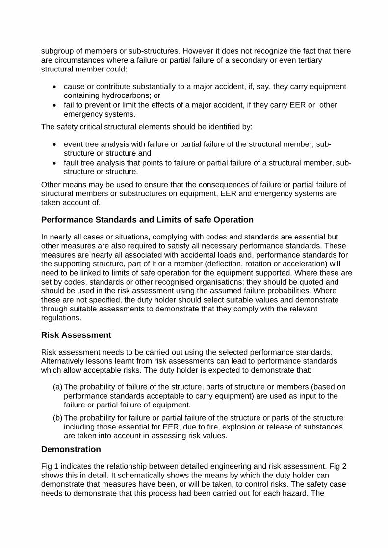
subgroup of members or sub-structures. However it does not recognize the fact that there are circumstances where a failure or partial failure of a secondary or even tertiary structural member could:
• cause or contribute substantially to a major accident, if, say, they carry equipment containing hydrocarbons; or
• fail to prevent or limit the effects of a major accident, if they carry EER or other emergency systems.
The safety critical structural elements should be identified by:
• event tree analysis with failure or partial failure of the structural member, sub-structure or structure and
• fault tree analysis that points to failure or partial failure of a structural member, sub-structure or structure.
Other means may be used to ensure that the consequences of failure or partial failure of structural members or substructures on equipment, EER and emergency systems are taken account of.
Performance Standards and Limits of safe Operation
In nearly all cases or situations, complying with codes and standards are essential but other measures are also required to satisfy all necessary performance standards. These measures are nearly all associated with accidental loads and, performance standards for the supporting structure, part of it or a member (deflection, rotation or acceleration) will need to be linked to limits of safe operation for the equipment supported. Where these are set by codes, standards or other recognised organisations; they should be quoted and should be used in the risk assessment using the assumed failure probabilities. Where these are not specified, the duty holder should select suitable values and demonstrate through suitable assessments to demonstrate that they comply with the relevant regulations.
Risk Assessment
Risk assessment needs to be carried out using the selected performance standards. Alternatively lessons learnt from risk assessments can lead to performance standards which allow acceptable risks. The duty holder is expected to demonstrate that:
(a) The probability of failure of the structure, parts of structure or members (based on performance standards acceptable to carry equipment) are used as input to the failure or partial failure of equipment.
(b) The probability for failure or partial failure of the structure or parts of the structure including those essential for EER, due to fire, explosion or release of substances are taken into account in assessing risk values.
Demonstration
Fig 1 indicates the relationship between detailed engineering and risk assessment. Fig 2 shows this in detail. It schematically shows the means by which the duty holder can demonstrate that measures have been, or will be taken, to control risks. The safety case needs to demonstrate that this process had been carried out for each hazard. The
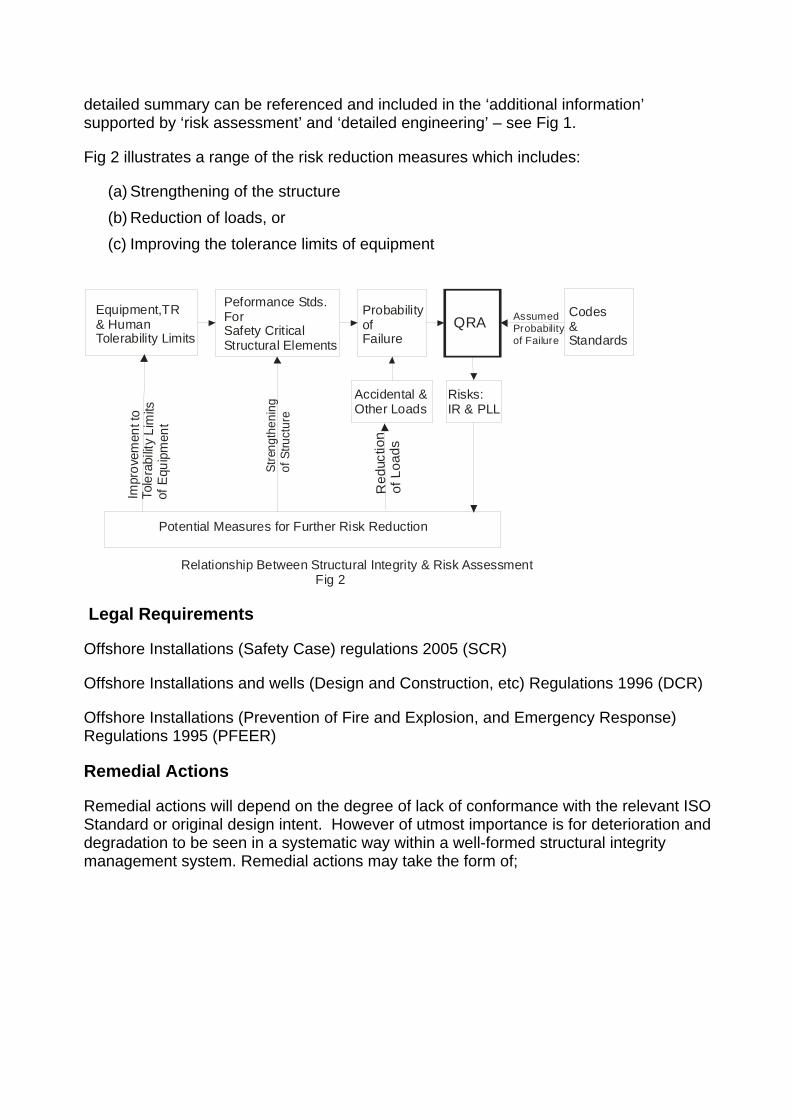
detailed summary can be referenced and included in the ‘additional information’ supported by ‘risk assessment’ and ‘detailed engineering’ – see Fig 1.
Fig 2 illustrates a range of the risk reduction measures which includes:
(a) Strengthening of the structure (b) Reduction of loads, or (c) Improving the tolerance limits of equipment
Equipment,TR & HumanTolerability Limits
Peformance Stds.ForSafety CriticalStructural Elements
ProbabilityofFailure
QRACodes&Standards
AssumedProbabilityof Failure
Risks:IR & PLL
Accidental &Other Loads
Potential Measures for Further Risk Reduction
Red
uctio
nof
Loa
ds
S tr e
n gt h
e ni n
gof
St ru
ctu r
e
Impr
ovem
ent t
oTo
lera
bilit
y L i
mits
o f E
quip
men
t
Relationship Between Structural Integrity & Risk Assessment Fig 2
Legal Requirements
Offshore Installations (Safety Case) regulations 2005 (SCR)
Offshore Installations and wells (Design and Construction, etc) Regulations 1996 (DCR)
Offshore Installations (Prevention of Fire and Explosion, and Emergency Response) Regulations 1995 (PFEER)
Remedial Actions
Remedial actions will depend on the degree of lack of conformance with the relevant ISO Standard or original design intent. However of utmost importance is for deterioration and degradation to be seen in a systematic way within a well-formed structural integrity management system. Remedial actions may take the form of;
• Re-analysis of integrity to ascertain theoretical level of integrity impairment leading to action plan;
• inspection to ascertain level of integrity impairment leading to reassessment of integrity;
• increased inspection intervals; • repairs; or • a combination of the above.
As indicated in the technical policy statement, it is expected that protective measures will be provided during initial design and construction as well as monitoring carried out during the life cycle. A number of possible control measures are listed below:
Initial design and construction
• Design and detailing to minimize stress concentrations and possible opportunities for crack initiation
• Design of connections and details with fatigue lives that are many times greater than the planned service life
• Construction of connections and details to ensure smooth weld profiles and avoid possible sources of defects
• Design and detailing to minimize opportunities for corrosion • Provision of coatings to protect against corrosion • Provision of cathodic protection systems to protect against corrosion • Assessment of redundancy and reserve strength in order to identify the criticality of
members and joints
Monitoring and management during the life cycle
• Periodic inspection to ensure that any degradation stays within acceptable limits. Clearly an important requirement is that acceptable limits are defined, using an appropriate mix of member and joint criticality, fatigue life, and past inspection history
• Continuous monitoring of integrity, which can include automatic leak in void spaces, stress and strain measurements, acoustic emission sensing, or natural frequency measurement.
• Taking appropriate action in the event of degradation that is outside acceptable limits. Action will need to be proportional to the scale of degradation and may include total or partial evacuation of staff, Further inspection and sizing (if required), assessment of deterioration using sound engineering principles, and repair or improvement where necessary
It is expected that most of these measures will be used for each installation. Close attention should be given to cases where reliance is placed solely on either initial measures or on in-service inspection.
Examples of Evidence
Loss of Air Gap:
The primary control of the extreme weather hazard is by means of provision of an appropriate air gap corresponding to a 10-4 wave. A smaller air gap for a jacket

supported topside will cause drag and inertia loads on the inundated members and the equipment they carry at an inappropriate frequency (and hence risk) level. This will also load the supporting members along the load path, all the way to the jacket members as global loads.
Global-
Inundation of part of topside will cause sharp increase in global load. This can cause excessive or plastic deformation of the jacket and overloading of the foundations. The deflection or relative displacement should be checked against the tolerability limits of risers, caissons, conductors, link bridges and any other vulnerable safety critical equipment or equipment essential for EER. Any possible damage or impaired performance the supported equipment should be checked and the consequences should be considered in the quantified risk assessment whose results are quoted in the safety case.
Local-
Inundation of equipment and structural members will increase the load on these members, the supporting members and connections possibly causing local failure or large deformations resulting in loss of adequate support to equipment causing them to tilt, deform or be disconnected from pipes or cables. If this equipment is safety critical or part of EER system, the supporting members should also be considered as safety critical elements. The consequences of any possible damage or impaired performance of the supported equipment should be checked and the consequences should be considered in the quantified risk assessment whose results are quoted in the safety case.
The potential measures for risk reduction should be considered or arguments presented as to why they are not or cannot be carried out. The outline of this process should be given in the safety case with the additional information listed in references. This example does not include any consideration of risks arising from the equipment damage arising directly due to inundation.
Relevant Publications
• ISO 13822 Basis of design of structures – Assessment of existing structures • UKOOA Guidelines VES06 - FPSO Design Guidance notes • SNAME 5-5A Site Specific Assessment of Jack Up Structures • DNV/SINTEF/BOMEL ULTIGUIDE – Best Practice Non Linear Analysis Guidelines • OTO 2001 010 Environmental Considerations • Offshore Information Sheet 2/2006 Offshore Installations (Safety Case) Regulations 2005
Regulation 12 Demonstrating compliance with the relevant statutory provisions
Appendix A
Regulations Details to be Provided in SC
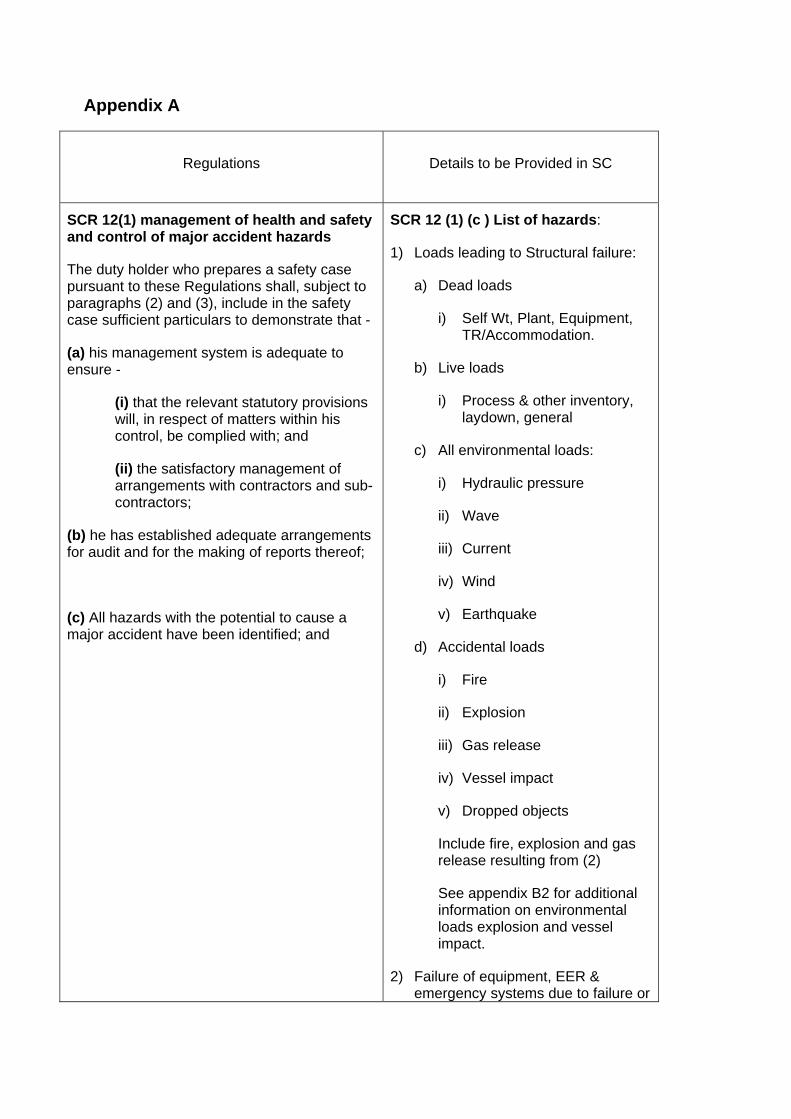
SCR 12(1) management of health and safety and control of major accident hazards
The duty holder who prepares a safety case pursuant to these Regulations shall, subject to paragraphs (2) and (3), include in the safety case sufficient particulars to demonstrate that -
(a) his management system is adequate to ensure -
(i) that the relevant statutory provisions will, in respect of matters within his control, be complied with; and
(ii) the satisfactory management of arrangements with contractors and sub-contractors;
(b) he has established adequate arrangements for audit and for the making of reports thereof;
(c) All hazards with the potential to cause a major accident have been identified; and
SCR 12 (1) (c ) List of hazards:
1) Loads leading to Structural failure:
a) Dead loads
i) Self Wt, Plant, Equipment, TR/Accommodation.
b) Live loads
i) Process & other inventory, laydown, general
c) All environmental loads:
i) Hydraulic pressure
ii) Wave
iii) Current
iv) Wind
v) Earthquake
d) Accidental loads
i) Fire
ii) Explosion
iii) Gas release
iv) Vessel impact
v) Dropped objects
Include fire, explosion and gas release resulting from (2)
See appendix B2 for additional information on environmental loads explosion and vessel impact.
2) Failure of equipment, EER & emergency systems due to failure or
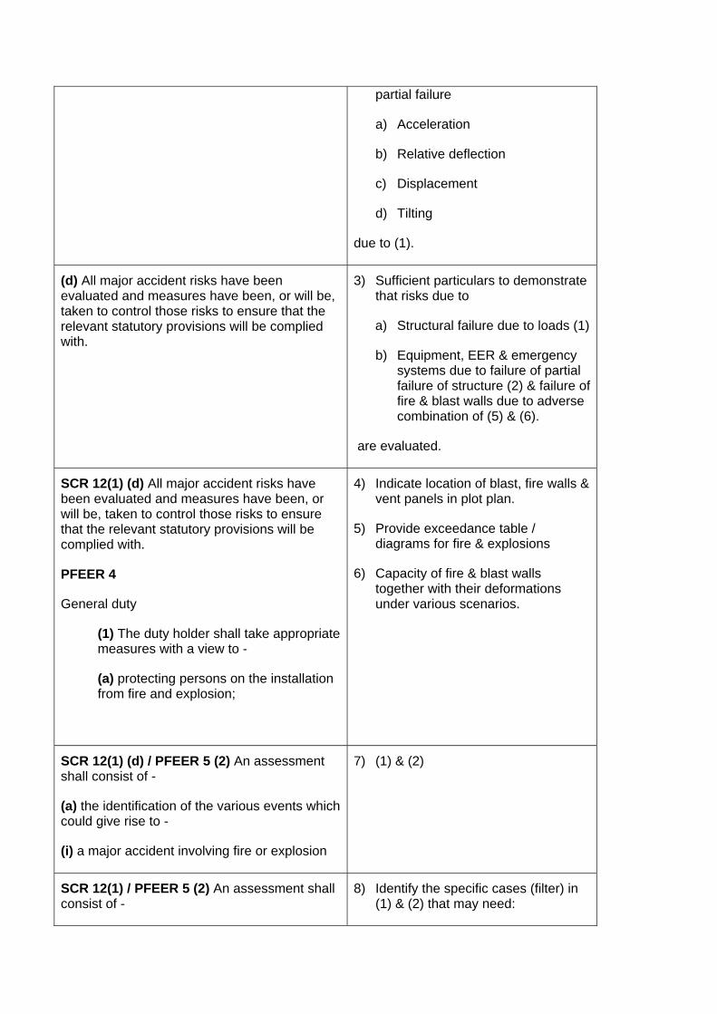
partial failure
a) Acceleration
b) Relative deflection
c) Displacement
d) Tilting
due to (1).
(d) All major accident risks have been evaluated and measures have been, or will be, taken to control those risks to ensure that the relevant statutory provisions will be complied with.
3) Sufficient particulars to demonstrate that risks due to
a) Structural failure due to loads (1)
b) Equipment, EER & emergency systems due to failure of partial failure of structure (2) & failure of fire & blast walls due to adverse combination of (5) & (6).
are evaluated.
SCR 12(1) (d) All major accident risks have been evaluated and measures have been, or will be, taken to control those risks to ensure that the relevant statutory provisions will be complied with.
PFEER 4
General duty
(1) The duty holder shall take appropriate measures with a view to -
(a) protecting persons on the installation from fire and explosion;
4) Indicate location of blast, fire walls & vent panels in plot plan.
5) Provide exceedance table / diagrams for fire & explosions
6) Capacity of fire & blast walls together with their deformations under various scenarios.
SCR 12(1) (d) / PFEER 5 (2) An assessment shall consist of -
(a) the identification of the various events which could give rise to -
(i) a major accident involving fire or explosion
7) (1) & (2)
SCR 12(1) / PFEER 5 (2) An assessment shall consist of -
8) Identify the specific cases (filter) in (1) & (2) that may need:
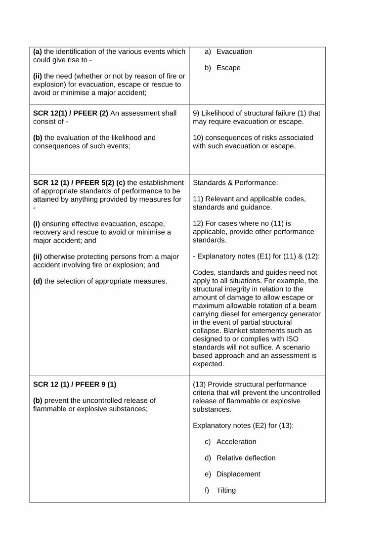
(a) the identification of the various events which could give rise to -
(ii) the need (whether or not by reason of fire or explosion) for evacuation, escape or rescue to avoid or minimise a major accident;
a) Evacuation
b) Escape
SCR 12(1) / PFEER (2) An assessment shall consist of -
(b) the evaluation of the likelihood and consequences of such events;
9) Likelihood of structural failure (1) that may require evacuation or escape.
10) consequences of risks associated with such evacuation or escape.
SCR 12 (1) / PFEER 5(2) (c) the establishment of appropriate standards of performance to be attained by anything provided by measures for -
(i) ensuring effective evacuation, escape, recovery and rescue to avoid or minimise a major accident; and
(ii) otherwise protecting persons from a major accident involving fire or explosion; and
(d) the selection of appropriate measures.
Standards & Performance:
11) Relevant and applicable codes, standards and guidance.
12) For cases where no (11) is applicable, provide other performance standards.
- Explanatory notes (E1) for (11) & (12):
Codes, standards and guides need not apply to all situations. For example, the structural integrity in relation to the amount of damage to allow escape or maximum allowable rotation of a beam carrying diesel for emergency generator in the event of partial structural collapse. Blanket statements such as designed to or complies with ISO standards will not suffice. A scenario based approach and an assessment is expected.
SCR 12 (1) / PFEER 9 (1)
(b) prevent the uncontrolled release of flammable or explosive substances;
(13) Provide structural performance criteria that will prevent the uncontrolled release of flammable or explosive substances.
Explanatory notes (E2) for (13):
c) Acceleration
d) Relative deflection
e) Displacement
f) Tilting
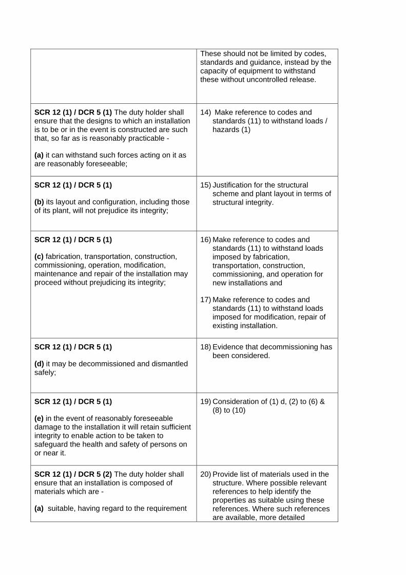
These should not be limited by codes, standards and guidance, instead by the capacity of equipment to withstand these without uncontrolled release.
SCR 12 (1) / DCR 5 (1) The duty holder shall ensure that the designs to which an installation is to be or in the event is constructed are such that, so far as is reasonably practicable -
(a) it can withstand such forces acting on it as are reasonably foreseeable;
14) Make reference to codes and standards (11) to withstand loads / hazards (1)
SCR 12 (1) / DCR 5 (1)
(b) its layout and configuration, including those of its plant, will not prejudice its integrity;
15) Justification for the structural scheme and plant layout in terms of structural integrity.
SCR 12 (1) / DCR 5 (1)
(c) fabrication, transportation, construction, commissioning, operation, modification, maintenance and repair of the installation may proceed without prejudicing its integrity;
16) Make reference to codes and standards (11) to withstand loads imposed by fabrication, transportation, construction, commissioning, and operation for new installations and
17) Make reference to codes and standards (11) to withstand loads imposed for modification, repair of existing installation.
SCR 12 (1) / DCR 5 (1)
(d) it may be decommissioned and dismantled safely;
18) Evidence that decommissioning has been considered.
SCR 12 (1) / DCR 5 (1)
(e) in the event of reasonably foreseeable damage to the installation it will retain sufficient integrity to enable action to be taken to safeguard the health and safety of persons on or near it.
19) Consideration of (1) d, (2) to (6) & (8) to (10)
SCR 12 (1) / DCR 5 (2) The duty holder shall ensure that an installation is composed of materials which are -
(a) suitable, having regard to the requirement
20) Provide list of materials used in the structure. Where possible relevant references to help identify the properties as suitable using these references. Where such references are available, more detailed
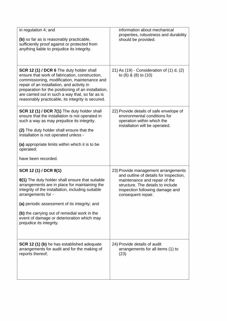
in regulation 4; and
(b) so far as is reasonably practicable, sufficiently proof against or protected from anything liable to prejudice its integrity.
information about mechanical properties, robustness and durability should be provided.
SCR 12 (1) / DCR 6 The duty holder shall ensure that work of fabrication, construction, commissioning, modification, maintenance and repair of an installation, and activity in preparation for the positioning of an installation, are carried out in such a way that, so far as is reasonably practicable, its integrity is secured.
21) As (19) - Consideration of (1) d, (2) to (6) & (8) to (10)
SCR 12 (1) / DCR 7(1) The duty holder shall ensure that the installation is not operated in such a way as may prejudice its integrity.
(2) The duty holder shall ensure that the installation is not operated unless -
(a) appropriate limits within which it is to be operated;
have been recorded.
22) Provide details of safe envelope of environmental conditions for operation within which the installation will be operated.
SCR 12 (1) / DCR 8(1)
8(1) The duty holder shall ensure that suitable arrangements are in place for maintaining the integrity of the installation, including suitable arrangements for -
(a) periodic assessment of its integrity; and
(b) the carrying out of remedial work in the event of damage or deterioration which may prejudice its integrity.
23) Provide management arrangements and outline of details for inspection, maintenance and repair of the structure. The details to include inspection following damage and consequent repair.
SCR 12 (1) (b) he has established adequate arrangements for audit and for the making of reports thereof;
24) Provide details of audit arrangements for all items (1) to (23)
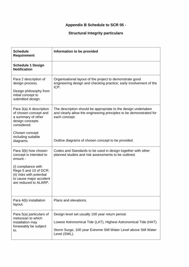
Appendix B Schedule to SCR 05 -
Structural Integrity particulars
Schedule Requirement
Information to be provided
Schedule 1 Design Notification
Para 2 description of design process.
Design philosophy from initial concept to submitted design.
Organisational layout of the project to demonstrate good engineering design and checking practice; early involvement of the ICP.
Para 3(a) A description of chosen concept and a summary of other design concepts considered.
Chosen concept including suitable diagrams.
The description should be appropriate to the design undertaken and clearly allow the engineering principles to be demonstrated for each concept.
Outline diagrams of chosen concept to be provided.
Para 3(b) how chosen concept is intended to ensure -
(i) compliance with Regs 5 and 10 of DCR; (ii) risks with potential to cause major accident are reduced to ALARP.
Codes and Standards to be used in design together with other planned studies and risk assessments to be outlined.
Para 4(b) installation layout.
Plans and elevations.
Para 5(a) particulars of metocean to which installation may forseeably be subject to.
Design level set usually 100 year return period.
Lowest Astronomical Tide (LAT), Highest Astronomical Tide (HAT).
Storm Surge, 100 year Extreme Still Water Level above Still Water Level (SWL).

Waves: Significant Wave height (Hs), Zero Crossing Period (Tz)
Maximum Wave height, Probable range of wave period.
Directionality of waves.
Air gap for 100 year return period, Air gap for 10,000 year return period.
Current: Surface, Mid Depth, Sea Bed
Wind (at 10m): 1 Hour mean, 1 minute mean, 3 Second mean.
Directionality.
Temperatures (maximum & minimum):
Air.
Sea surface.
Snow and Ice Loading:
Thickness and density as a function of height.
Para 5(b) particulars of properties of sea bed and subsoil at location.
The properties of the seabed at the location, sufficient for engineering design, should be given. These will usually be based on a site investigation strategy based on boreholes and cone penetrometer tests to enable engineering design of foundations to be undertaken.
Para 7 general description by which the management system will ensure structure will be designed, selected, constructed and commissioned to control major accident risks to comply with relevant statutory provisions.
An outline of the structural integrity management system.
Schedule 2 Operation of a production installation
Para 4(a) description with suitable diagrams of main and secondary structure and its
The meaning of this term is that suitable legible drawings are required of the structures in the safety case. There should be no difficulties in producing these drawings as they are part of the successful record and conclusion of the design, construction, and verification processes, and as the benchmark for in-service
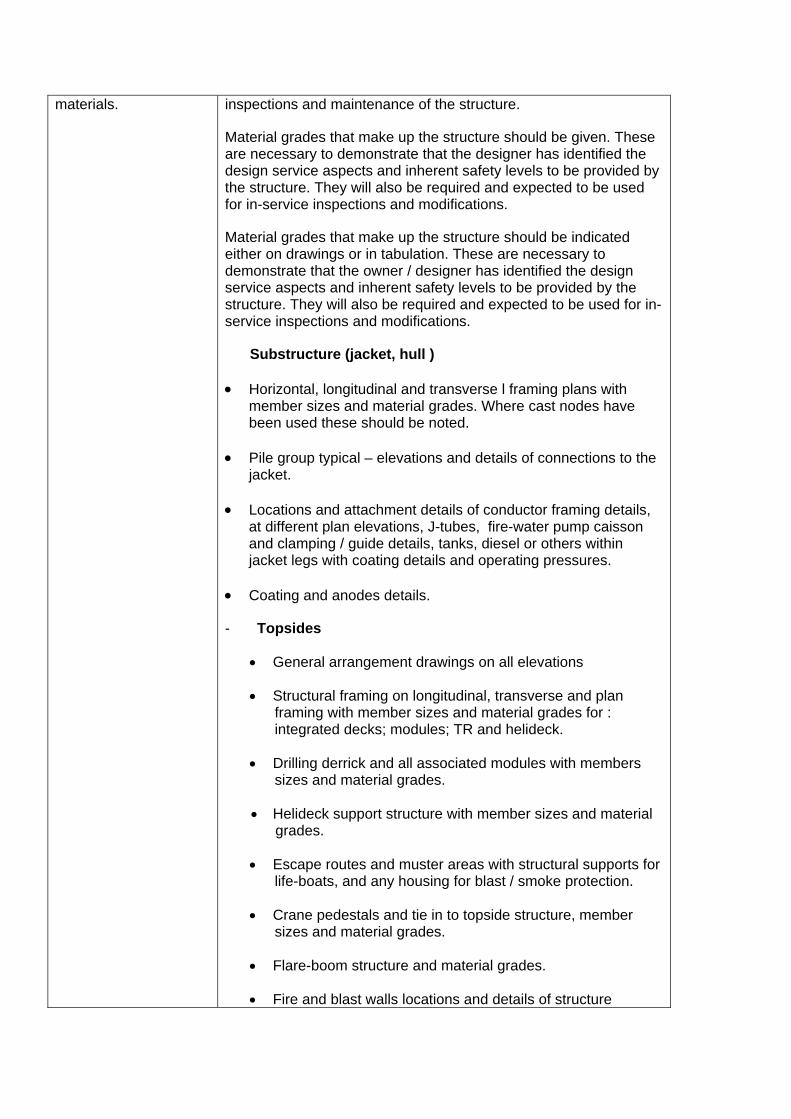
materials. inspections and maintenance of the structure.
Material grades that make up the structure should be given. These are necessary to demonstrate that the designer has identified the design service aspects and inherent safety levels to be provided by the structure. They will also be required and expected to be used for in-service inspections and modifications.
Material grades that make up the structure should be indicated either on drawings or in tabulation. These are necessary to demonstrate that the owner / designer has identified the design service aspects and inherent safety levels to be provided by the structure. They will also be required and expected to be used for in-service inspections and modifications.
Substructure (jacket, hull )
• Horizontal, longitudinal and transverse l framing plans with member sizes and material grades. Where cast nodes have been used these should be noted.
• Pile group typical – elevations and details of connections to the jacket.
• Locations and attachment details of conductor framing details, at different plan elevations, J-tubes, fire-water pump caisson and clamping / guide details, tanks, diesel or others within jacket legs with coating details and operating pressures.
• Coating and anodes details.
- Topsides
• General arrangement drawings on all elevations
• Structural framing on longitudinal, transverse and plan framing with member sizes and material grades for : integrated decks; modules; TR and helideck.
• Drilling derrick and all associated modules with members sizes and material grades.
• Helideck support structure with member sizes and material grades.
• Escape routes and muster areas with structural supports for life-boats, and any housing for blast / smoke protection.
• Crane pedestals and tie in to topside structure, member sizes and material grades.
• Flare-boom structure and material grades.
• Fire and blast walls locations and details of structure
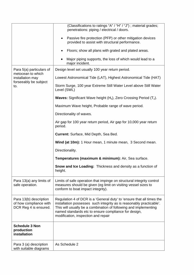
(Classifications to ratings “A” / “H” / “J”) ; material grades; penetrations: piping / electrical / doors.
• Passive fire protection (PFP) or other mitigation devices provided to assist with structural performance.
• Floors; show all plans with grated and plated areas.
• Major piping supports, the loss of which would lead to a major incident.
Para 5(a) particulars of metocean to which installation may forseeably be subject to.
Design level set usually 100 year return period.
Lowest Astronomical Tide (LAT), Highest Astronomical Tide (HAT)
Storm Surge, 100 year Extreme Still Water Level above Still Water Level (SWL)
Waves: Significant Wave height (Hs), Zero Crossing Period (Tz).
Maximum Wave height, Probable range of wave period.
Directionality of waves.
Air gap for 100 year return period, Air gap for 10,000 year return period.
Current: Surface, Mid Depth, Sea Bed.
Wind (at 10m): 1 Hour mean, 1 minute mean, 3 Second mean.
Directionality.
Temperatures (maximum & minimum): Air, Sea surface.
Snow and Ice Loading: Thickness and density as a function of height.
Para 13(a) any limits of safe operation.
Limits of safe operation that impinge on structural integrity control measures should be given (eg limit on visiting vessel sizes to conform to boat impact integrity).
Para 13(b) description of how compliance with DCR Reg 4 is ensured.
Regulation 4 of DCR is a ‘General duty‘ to ‘ensure that all times the installation possesses such integrity as is reasonably practicable’. This will usually be a combination of following and implementing named standards etc to ensure compliance for design, modification, inspection and repair
Schedule 3 Non production installation
Para 3 (a) description with suitable diagrams
As Schedule 2
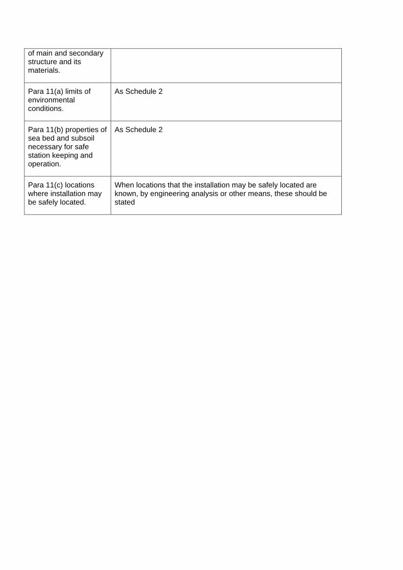
of main and secondary structure and its materials.
Para 11(a) limits of environmental conditions.
As Schedule 2
Para 11(b) properties of sea bed and subsoil necessary for safe station keeping and operation.
As Schedule 2
Para 11(c) locations where installation may be safely located.
When locations that the installation may be safely located are known, by engineering analysis or other means, these should be stated