technical note - tn 086: 2015 - transport for nsw note - tn 086: 2015 ... subject: withdrawal of tmd...
TRANSCRIPT

Technical Note - TN 086: 2015
© State of NSW through Transport for NSW Page 1 of 1
Technical Note - TN 086: 2015
Subject: Withdrawal of TMD 0001 CAD Manual- All sections (except Section 5 – Electrical Operating Diagrams)
Issued date: 01 March 2016
Effective date: 01 March 2016
This technical note is issued by the Asset Standards Authority as a notification to remove from
use the RailCorp standard TMD 0001 CAD Manual- All sections, Version 2.3 (except section 5 –
Electrical operating diagrams).
TMD 0001 CAD Manual- All sections (except section 5 – Electrical operating diagrams) are
legacy documents and shall be used for reference purposes only. ASA standard
T MU MD 00006 ST Engineering Drawings and CAD Requirements, Version 1.0 supersedes this
document from 01 March 2016.
Authorisation:
Technical content prepared by
Checked and approved by
Interdisciplinary coordination checked by
Authorised for release
Signature
Date
Name Harpreet Singh Jagath Peiris John Paff Graham Bradshaw
Position CAD Specialist Manager Network Standards
A/Chief Engineer Rail Director Network Standards and Services
For queries regarding this document [email protected]
www.asa.transport.nsw.gov.au

Engineering Manual Design Track Design
TMD 0001
Engi
neer
ing
Man
ual
CAD AND DRAFTING MANUAL – TRACK DESIGN – SECTION 7
Version 2.2
Issued September 2010
Owner: Applications Manager – RailCAD
Approved by:
Brent Mallam Applications Manager RailCAD
Authorised by:
Mike Hogan General Manager Professional Services
Disclaimer This document was prepared for use on the RailCorp Network only. RailCorp makes no warranties, express or implied, that compliance with the contents of this document shall be sufficient to ensure safe systems or work or operation. It is the document user’s sole responsibility to ensure that the copy of the document it is viewing is the current version of the document as in use by RailCorp. RailCorp accepts no liability whatsoever in relation to the use of this document by any party, and RailCorp excludes any liability which arises in any manner by the use of this document. Copyright The information in this document is protected by Copyright and no part of this document may be reproduced, altered, stored or transmitted by any person without the prior consent of RailCorp.
UNCONTROLLED WHEN PRINTED Page 1 of 54 Sup
erse
ded
by T
MU
MD
000
06 S
T v1
.0

RailCorp Engineering Manual — Design — Track Design CAD and Drafting Manual – Track Design – Section 7 TMD 0001
© RailCorp Page 2 of 54 Issued September 2010 UNCONTROLLED WHEN PRINTED Version 2.2
Document control
Version Date Summary of change 1.0 Aug 2005 First issue
1.1 Nov 2005 Section numbering updated, Reference corrections and Document Control Page added
1.2 Jan 2006 Alteration after stake holder review
2.0 April 2009 Major review. Re-formatted and renumbered to new system. Cell libraries and level names revised.
2.1 September 2010 Application of TMA 400 format
Sup
erse
ded
by T
MU
MD
000
06 S
T v1
.0

RailCorp Engineering Manual — Design — Track Design CAD and Drafting Manual – Track Design – Section 7 TMD 0001
© RailCorp Page 3 of 54 Issued September 2010 UNCONTROLLED WHEN PRINTED Version 2.2
Contents
7 Track Services CAD Standards .............................................................................................5 7.1 Introduction ................................................................................................................5 7.2 Drawings....................................................................................................................5
7.2.1 Standard Drawings.....................................................................................5 7.2.2 Drawing Types List.....................................................................................5
7.2.2.1 Horizontal Alignments .................................................................6 7.2.2.2 Vertical Alignments .....................................................................6 7.2.2.3 Turnout Detail / Timber and Plating ............................................6 7.2.2.4 Detail Surveys.............................................................................6 7.2.2.5 Cross Sections............................................................................7 7.2.2.6 Miscellaneous Drawings and Diagrams......................................7
7.3 Drawing Requirements ..............................................................................................7 7.3.1 Horizontal Alignment Drawings ..................................................................7
7.3.1.1 General Requirements:...............................................................7 7.3.1.2 Drawing Content: ........................................................................7 7.3.1.3 Track Setting Out Details ............................................................9
7.3.2 Vertical Alignment Drawings ....................................................................10 7.3.2.1 General Requirements:.............................................................10 7.3.2.2 Drawing Content: ......................................................................10
7.3.3 Turnout Detail/Timbering And Plating Drawing........................................11 7.3.3.1 Field Layout for Tangential Turnouts ........................................12 7.3.3.2 Tangential Turnouts – Tie layout and details............................12 7.3.3.3 Conventional Turnouts – Timber and plating............................13 7.3.3.4 Components - General Requirements ......................................14 7.3.3.5 Components - Drawing Content ...............................................14
7.3.4 Detail Survey Drawing..............................................................................14 7.3.4.1 General Requirements:.............................................................14 7.3.4.2 Drawing Content: ......................................................................14 7.3.4.3 Miscellaneous and Additional Data:..........................................15
7.3.5 Cross Section Drawings...........................................................................15 7.3.5.1 General Requirements:.............................................................15 7.3.5.2 Drawing Content: ......................................................................15 7.3.5.3 Cross Sections showing Design Proposals will
include:......................................................................................15 7.4 CAD Standards........................................................................................................16
7.4.1 Linework, Line Styles, Colour and Text....................................................16 7.5 Seed Files................................................................................................................16 7.6 Self Referencing ......................................................................................................16 7.7 Cell Libraries............................................................................................................16 7.8 Drawing Standards ..................................................................................................16
7.8.1 Title Blocks ...............................................................................................16 7.8.2 Additional Information...............................................................................17 7.8.3 Specific Drawing Products .......................................................................17 7.8.4 RailCorp Standard Drawings....................................................................17
Sup
erse
ded
by T
MU
MD
000
06 S
T v1
.0
RailCorp Engineering Manual — Design — Track Design CAD and Drafting Manual – Track Design – Section 7 TMD 0001
© RailCorp Page 4 of 54 Issued September 2010 UNCONTROLLED WHEN PRINTED Version 2.2
7.8.5 Folder and File Names.............................................................................17 7.8.5.1 Folder names: ...........................................................................17 7.8.5.2 File names ................................................................................18
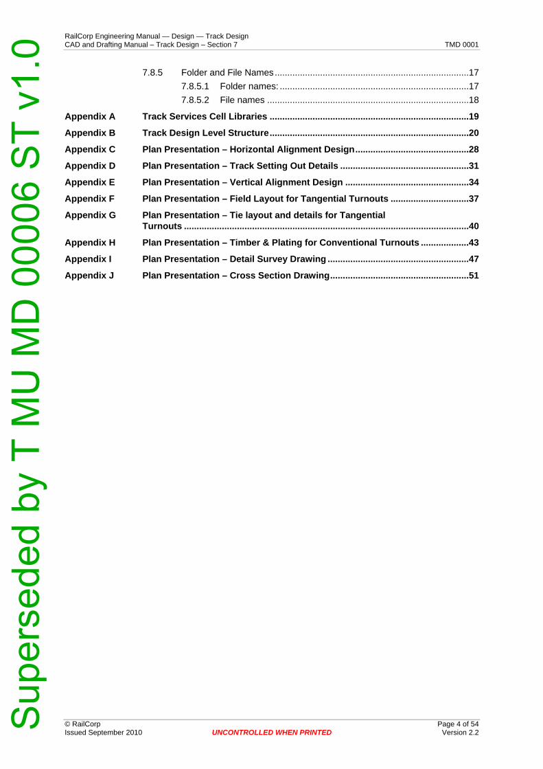
Appendix A Track Services Cell Libraries ...............................................................................19 Appendix B Track Design Level Structure...............................................................................20 Appendix C Plan Presentation – Horizontal Alignment Design.............................................28 Appendix D Plan Presentation – Track Setting Out Details ...................................................31 Appendix E Plan Presentation – Vertical Alignment Design .................................................34 Appendix F Plan Presentation – Field Layout for Tangential Turnouts ...............................37 Appendix G Plan Presentation – Tie layout and details for Tangential
Turnouts .................................................................................................................40 Appendix H Plan Presentation – Timber & Plating for Conventional Turnouts ...................43 Appendix I Plan Presentation – Detail Survey Drawing ........................................................47 Appendix J Plan Presentation – Cross Section Drawing.......................................................51
Sup
erse
ded
by T
MU
MD
000
06 S
T v1
.0

RailCorp Engineering Manual — Design — Track Design CAD and Drafting Manual – Track Design – Section 7 TMD 0001
© RailCorp Page 5 of 54 Issued September 2010 UNCONTROLLED WHEN PRINTED Version 2.2
7 Track Services CAD Standards
7.1 Introduction This section of the MicroStation V8 based CADD Manual is intended to:
• Standardise the preparation of drawings • Simplify various aspects of the work • Provide guidance on detailing • Secure consistency in quality and appearance
It applies to track design drawings produced by RailCorp Engineering, Track Services, or engaged sub-consultants. If, in special cases or for particular clients, it becomes necessary to deviate from these practices, then the Manager of Track Services must first give approval.
Corporation-wide standards are to be found in Section 1 of this manual, or in the Australian Standard AS1100, parts 101 & 501. This section defines the standards to be applied to drawings specific to the track design discipline. Generally, all drawings shall comply with Australian Standards and any project specific special requirements.
All references to Australian Standards refer to the latest edition.
7.2 Drawings All drawings shall be produced, where possible, on computer aided drafting (CAD) workstations running MicroStation V8.5 or higher software. Completed and approved drawings must show sufficient details to meet the drawings’ purpose and satisfy the client’s requirements. Drawings should be read in conjunction with the specification, if any, and where conflict occurs between the two, the drawings take precedence (unless the specification expressly states otherwise).
7.2.1 Standard Drawings Standard drawings eliminate repetition by showing details which are typical or representative for particular types of projects. They can be issued, without alteration, to many different clients on different projects.
Standard drawings shall be prepared, registered, etc, in accordance with this manual in the same way as ordinary drawings.
For each project, the full set of ordinary drawings and standard drawings are brought together to form the project drawings. A complete set of project drawings shows the full extent of the work.
7.2.2 Drawing Types List The Track Services Section supplies drawing products based on the drawing types listed below.
• Horizontal Alignments • Vertical Alignments • Turnout Detail / Timbering and Plating • Detail Surveys • Cross Sections • Miscellaneous Drawings and Diagrams
Sup
erse
ded
by T
MU
MD
000
06 S
T v1
.0
RailCorp Engineering Manual — Design — Track Design CAD and Drafting Manual – Track Design – Section 7 TMD 0001
© RailCorp Page 6 of 54 Issued September 2010 UNCONTROLLED WHEN PRINTED Version 2.2
These products are digitally prepared using CAD software and are provided to various RailCorp Engineering design disciplines who are involved in the project. These products are also supplied to contractual personnel who provide services to this corporation.
Copies of the majority of these drawing products are submitted to the RailCorp Plan Room for storage and safekeeping.
For a summary of each product refer to the following pages:
7.2.2.1 Horizontal Alignments Horizontal alignment drawings depict the coordinated track alignment and are often referred to as setting out drawings. The detailed alignment must conform to the relevant RailCorp design standards. They should be prepared to a concise degree of accuracy and show the detail and information necessary to enable field marking and setting out by surveyors.
The horizontal alignment data shown would include coordinated frame points, curve details, transition details, straight details, track centres, turnout details, velocity and superelevation, kilometrage values, kilometrage adjustments, control marks, horizontal and vertical coordinate origins, and the coordinate system.
The digital data that forms the horizontal alignment drawing should be prepared so that it may be utilised by the various civil design disciplines and contractors that form part of the project team. This would include a standard level mapping structure that would enable filtering of drawing elements.
Horizontal Alignment drawing numbers are provided by the RailCorp Planroom.
7.2.2.2 Vertical Alignments Vertical alignment drawings (longsections) depict the track grades for track alignment and along with horizontal alignment provide the information necessary to enable field marking and setting out by surveyors.
The vertical alignment data shown would include kilometrage locations, diagrammatic representation of the horizontal alignment, existing rail levels, track lifts, design rail levels, grade values, vertical curve details, grade intersection levels, control or bench marks and existing and design profiles.
All features that affect design grades should be included in the longsection ie. platforms, underbridges, overbridges, underpasses, culverts, turnouts etc.
Vertical Alignment drawing numbers are provided by the RailCorp Planroom.
7.2.2.3 Turnout Detail / Timber and Plating Turnout detail drawings are an integral step in the track design process. These drawings along with timbering and plating drawings enable the installation of turnouts and turnout components to acceptable standards. These drawings depict and detail track components such as turnout type, turnout parameters and setting out details.
Turnout detail / timbering and plating drawing numbers are provided by the RailCorp Planroom.
7.2.2.4 Detail Surveys Detail Survey drawings depict the existing and natural topographical features. These features are radiated by survey methods or provided by means of aerial mapping. This
Sup
erse
ded
by T
MU
MD
000
06 S
T v1
.0

RailCorp Engineering Manual — Design — Track Design CAD and Drafting Manual – Track Design – Section 7 TMD 0001
© RailCorp Page 7 of 54 Issued September 2010 UNCONTROLLED WHEN PRINTED Version 2.2
documented information forms the terrain model for locations where engineering design proposals are planned or considered. Also the detail survey drawing forms the base detail necessary for various design procedures and use by other design disciplines.
Detail survey drawing numbers are provided by the RailCorp Planroom.
7.2.2.5 Cross Sections Cross Section drawings depict a series of cross sections taken perpendicular to the track and are used in the design process for determining earthwork formation design and earthwork quantities.
The cross section data shown would include levels, offsets from existing or design alignment centreline, labels and features. The kilometrage location for each section should be indicated and each section viewed and compiled in the direction of ascending chainage.
Cross section drawing numbers are provided by the RailCorp Planroom.
7.2.2.6 Miscellaneous Drawings and Diagrams Miscellaneous drawings or diagrams are prepared in the Track Services section. These drawings would include proposals, layouts, kinematic or clearance investigations, tunnel profiles and diagrams for reports.
Miscellaneous drawings and diagrams are registered in the plan room using the EDMS system dependent on their desired distribution or publication requirements. Some miscellaneous drawings and diagrams may not be registered but form part of the documentation in the job file.
7.3 Drawing Requirements
7.3.1 Horizontal Alignment Drawings Horizontal alignment drawings are used to document horizontal track alignment for use by various engineering disciplines.
7.3.1.1 General Requirements: To be drawn on a standard A1 sheet preferably but acceptable as a roll plan to A1 sheet width.
The content orientation shall be Sydney on the left with rail tracks as horizontal as possible.
Drawn at a scale of 1 : 500.
North point and grid related to the azimuth of the survey.
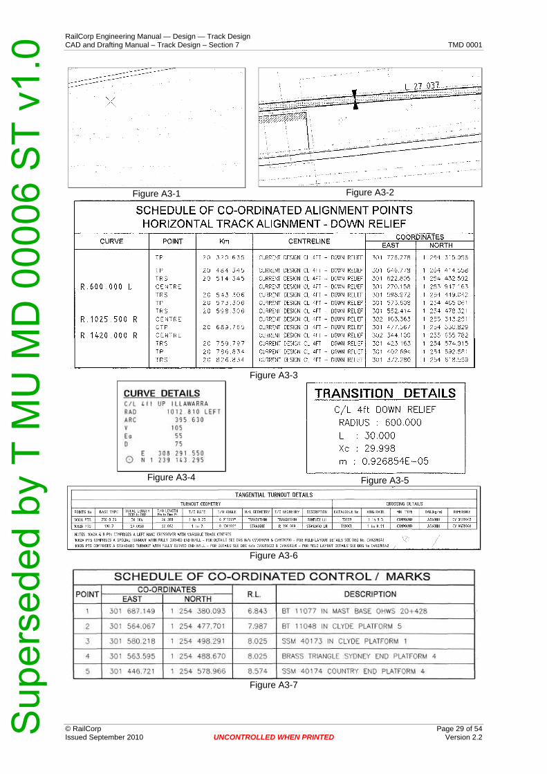
7.3.1.2 Drawing Content: The following information should be displayed. (See Appendix C).
Requirement Comment Figure Ref
Detail survey Show in background as half tone / 75% Surveyed features to have annotation for all relevant/significant information
A3-1
Sup
erse
ded
by T
MU
MD
000
06 S
T v1
.0

RailCorp Engineering Manual — Design — Track Design CAD and Drafting Manual – Track Design – Section 7 TMD 0001
© RailCorp Page 8 of 54 Issued September 2010 UNCONTROLLED WHEN PRINTED Version 2.2
Requirement Comment Figure Ref
Tracks No more than two tracks to be documented on one sheet Document tracks in pairs Track subject to design to be shaded as shown in Legend
A3-2
Existing alignment
Depicted graphically with associated labeling.
Co-ordinates for frame points.
Point description, kilometrage, Centre Line name [based on Line Name], Easting & Northing Separate schedules for the Down and Up track frame points
A3-3
Design centreline
Information for each sheet should be documented on each sheet. You should not have to refer back to an index sheet to sort the alignment
Horizontal alignment
Documented in schedule form A3-3
Curve Details Show Track Name, Radius and direction, Arc Length, Velocity, Ea, Deficiency, Centre-Easting & Northing
A3-4
Transition Details
Show Track Name, Radius, Length, Xc, M & Ramp Rate Show non standard ramps by dimension with start and finish km noted (Ea Points)
A3-5
Straight Details
Show Bearing & Distance A3-7
Track Centres Show "6ft" / variable A3-7
Show at scale - Document full detail on the setting out drawing
A3-9 Turnouts
Show turnout details in schedule form. Tangential and Conventional as separate schedules)
A3-6
Design Speed Show in notes
Grid. Show at 50m intervals over the whole sheet. This can be scale dependent
A3-8
Kilometrage Values
Place at 90° to track. Orient so that they can be read in the direction of increasing kilometrage from top to bottom when drawing is rotated 90° clockwise
A3-9
Kilometrage adjustments
In accordance with ESC 210 A3-13
Show in schedule form. Include identification number, if any, type of mark (SSM / BT etc) and location.
A3-7 Survey Control Marks
Show mark location on drawing A3-10
Co-ordinate System
Show Horizontal co-ordinate origins, Vertical datum origins and co-ordinate system (eg NGA, ISG, Plane Rectangular) in notes
A3-12
From & To. Show "From XXX" (usually "From Sydney") and "To YYYY" with Sydney on left of the drawing sheet
A3-11
Multiple sheets All drawing detail other than the rails is to be deleted beyond the join lines
A3-12
Notes A3-13
References A3-14
Legend A3-15
Scale A3-16
Sup
erse
ded
by T
MU
MD
000
06 S
T v1
.0
RailCorp Engineering Manual — Design — Track Design CAD and Drafting Manual – Track Design – Section 7 TMD 0001
© RailCorp Page 9 of 54 Issued September 2010 UNCONTROLLED WHEN PRINTED Version 2.2
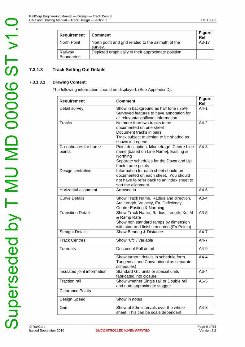
Requirement Comment Figure Ref
North Point North point and grid related to the azimuth of the survey.
A3-17
Railway Boundaries
Depicted graphically in their approximate position
7.3.1.3 Track Setting Out Details
7.3.1.3.1 Drawing Content:
The following information should be displayed. (See Appendix D).
Requirement Comment Figure Ref
Detail survey Show in background as half tone / 75% Surveyed features to have annotation for all relevant/significant information
A4-1
Tracks No more than two tracks to be documented on one sheet Document tracks in pairs Track subject to design to be shaded as shown in Legend
A4-2
Co-ordinates for frame points.
Point description, kilometrage, Centre Line name [based on Line Name], Easting & Northing Separate schedules for the Down and Up track frame points
A4-3
Design centreline Information for each sheet should be documented on each sheet. You should not have to refer back to an index sheet to sort the alignment
Horizontal alignment Arrowed in A4-5
Curve Details Show Track Name, Radius and direction, Arc Length, Velocity, Ea, Deficiency, Centre-Easting & Northing
A3-4
Transition Details Show Track Name, Radius, Length, Xc, M & Ramp Rate Show non standard ramps by dimension with start and finish km noted (Ea Points)
A3-5
Straight Details Show Bearing & Distance A4-7
Track Centres Show "6ft" / variable A4-7
Document Full detail A4-9 Turnouts
Show turnout details in schedule form. Tangential and Conventional as separate schedules)
A4-4
Insulated joint information Standard GIJ units or special units fabricated into closure
A6-4
Traction rail Show whether Single rail or Double rail and note approximate stagger
A6-5
Clearance Points
Design Speed Show in notes
Grid. Show at 50m intervals over the whole sheet. This can be scale dependent
A4-8
Sup
erse
ded
by T
MU
MD
000
06 S
T v1
.0

RailCorp Engineering Manual — Design — Track Design CAD and Drafting Manual – Track Design – Section 7 TMD 0001
© RailCorp Page 10 of 54 Issued September 2010 UNCONTROLLED WHEN PRINTED Version 2.2
Requirement Comment Figure Ref
Kilometrage Values Place at 90° to track. Orient so that they can be read in the direction of increasing kilometrage from top to bottom when drawing is rotated 90° clockwise
A4-12
Kilometrage adjustments. In accordance with ESC 210 A4-13
Survey Control Marks Show in schedule form. Include identification number, if any, type of mark (SSM / BT etc) and location.
A4-6
Co-ordinate System Show Horizontal and Vertical co-ordinate origins and co-ordinate system in notes
A4-10
From & To. Show "From XXX" (usually "From Sydney") and "To YYYY" with Sydney on left of the drawing sheet
A4-14
Multiple sheets All drawing detail other than the rails is to be deleted beyond the join lines
A3-12
Track pulls Show pulls required to get existing track back to design
A4-15
Notes, references, legend & scale
A3-13 - 16
7.3.2 Vertical Alignment Drawings Vertical alignment drawings (Longsections) are used to document vertical track alignment for use by various engineering disciplines.
7.3.2.1 General Requirements: To be drawn on a standard A1 sheet preferably but acceptable as a roll plan to A1 sheet width.
7.3.2.2 Drawing Content: The following information should be displayed. (See Appendix E)
Requirement Comment Figure Ref
Line name Show as heading in top left corner of section
A5-1
Kilometrage location The running kilometrage should include labels for the horizontal and vertical alignment frame points. Include kilometrage adjustments
A5-2
Diagrammatic representation of the horizontal alignment
With the cardinal points, Ea and radius noted.
A5-3
Existing rail levels Interpolated to 20m intervals A5-4
Track Lifts and Lowering From existing to design A5-5
Grade and Intersection points
IP metrage and RL
Design Rail Levels Note to be added to the rail profile nominating the adjoining grades
A5-6
Grade Values Grades to be rounded in accordance with ESC 210.
A5-7
Sup
erse
ded
by T
MU
MD
000
06 S
T v1
.0

RailCorp Engineering Manual — Design — Track Design CAD and Drafting Manual – Track Design – Section 7 TMD 0001
© RailCorp Page 11 of 54 Issued September 2010 UNCONTROLLED WHEN PRINTED Version 2.2
Requirement Comment Figure Ref
Line name Show as heading in top left corner of section
A5-1
Kilometrage location The running kilometrage should include labels for the horizontal and vertical alignment frame points. Include kilometrage adjustments
A5-2
Diagrammatic representation of the horizontal alignment
With the cardinal points, Ea and radius noted.
A5-3
Grading With included km
Vertical Curve Details IP value to be shown and associated radii A5-8
Construction or Interim Grades
Tie in-grades to existing to be included at concept stage. Helps define the scope for survey
A5-9
Control and Bench Marks
Existing and Design Profile A5-10
Formation Profile When required. (i.e. 750mm below rail) A5-10
Track Layout Diagram Showing crossovers/turnouts where necessary.
A5-19
Overbridges, Underbridges, tunnels, pipes, culverts, Turnouts, Platforms (level or standard) Topographic Features. Show above and describe the profile at their longitudinally plotted location.
A5-12
Underside of girder levels. (Overbridges) A5-13
Existing & Proposed Design Structures
Deck levels. (Underbridges)
Ballast depth when available A5-14
Contact and catenaries When required for Over Head Wire design A5-11
Design velocity (speed)
Datum Level, km and survey origin
Notes
Special super ramps
A5-15
Scale Preferred ratio 100:1000 or other recognised scales. Bar scale also to be shown
A5-16
References, legend A5-17 - 18
7.3.3 Turnout Detail/Timbering And Plating Drawing Timbering & Plating drawings are used to document the geometry and various components used to make up a turnout, crossover, diamond or slip etc.
Component drawings are used to detail the various track components for manufacturing purposes.
Sup
erse
ded
by T
MU
MD
000
06 S
T v1
.0

RailCorp Engineering Manual — Design — Track Design CAD and Drafting Manual – Track Design – Section 7 TMD 0001
7.3.3.1 Field Layout for Tangential Turnouts Description
This drawing is intended to provide a plan, laid out in correct orientation, for the track crew carrying out pre-assembly. Position of Insulated Joints, type of IJ units and cant sets requirements are shown. Initial layout of ties (bearers) allows 'rough' layout to be as close as possible to final layout. This minimises inaccuracies as well as reducing re-work.
The following information should be displayed. (See Appendix F)
Figure Ref Requirement Comment
Turnout Type and parameters
Tie Layout Initial Layout for Turnout & End infill ties A6-1
Final Layouts for Turnout & End infill ties A6-2
Setting Out dimensions for turnout & end infill steelwork A6-3
Insulated joint information Standard GIJ units or special units fabricated into closure
A6-4
Traction rail Show whether Single rail or Double rail and note approximate stagger
A6-5
In-bearer Tie arrangements at points (where required)
Closure details including specials with built in GIJs A6-6
Closure and check rail carrier labels
A,B,C,D,E,F,G,H,K etc – in traditional sequence.
A6-7
Additional plating Adjacent to GIJs A6-9
Notes, references, drawing number & scale
A6-8
Figure 1 - Closure naming conventions
7.3.3.2 Tangential Turnouts – Tie layout and details The following information should be displayed. (See Appendix G)
Figure Ref Requirement Comment
Turnout details Location, points numbers, type, length Concrete Turnout Tie Layout
Spacing of bearers (between bearers and cumulative on both sides) from commencement of cant reducing plates at either end.
A7-1
© RailCorp Page 12 of 54 Issued September 2010 UNCONTROLLED WHEN PRINTED Version 2.2 Sup
erse
ded
by T
MU
MD
000
06 S
T v1
.0

RailCorp Engineering Manual — Design — Track Design CAD and Drafting Manual – Track Design – Section 7 TMD 0001
© RailCorp Page 13 of 54 Issued September 2010 UNCONTROLLED WHEN PRINTED Version 2.2
Requirement Comment Figure Ref
Length of each bearer A-1 Bearer Details Identification No. of each bearer A7-1 &
A7-6 Pad Details Pad dimensions for all turnout base plates A7-2 Closure details including specials with built in GIJs A7-3 Closure and check rail carrier labels
A,B,C,D,E,F,G,H,K etc – in traditional sequence.
A7-4
Screw spike inserts Typical details A7-5 Method of securing rails with double clip washers
(where required)
Insulated joint information. Standard GIJ units or special units fabricated into closure
A7-7
Traction rail Show whether Single rail or Double rail and note approximate stagger
A7-8
In-bearer Tie arrangements at points Notes, references and scale.
A7-9
7.3.3.3 Conventional Turnouts – Timber and plating The following information should be displayed. (See Appendix H)
Requirement Comment Figure Ref
Timber & Plating Details Length and spacing of bearers from commencement of cant reducing plates at either end. Identification No. of each plate
A8-1
Item numbers to be referenced to components on drawing. Includes:
A8-2
Table of pandrol base plates A8-3 Table of timber bearers A8-4 Table of closures A8-5 Table of heelblock dimensions A8-6
Table of materials
Table of standard plates A8-7 Setting out dimensions for turnout steelwork
includes offsets to mainline and turnout for field layout and check purposes
A8-8
Switch, stockrail and checkrail details
includes offsets, mid-ordinates, radii and curvature direction of these components
A8-9
Crossing Details Crossing rate and XL catalogue number shown in Material List with reference to detail drawing
Insulated joint information. Show standard GIJ units or special units fabricated into closure
Traction rail Show whether Single rail or Double rail and note approximate stagger
Closure details including specials with built in GIJs Closure and check rail carrier labels
A,B,C,D,E,F,G,H,K etc – in traditional sequence.
A8-10
Notes, references and scale. A8-11
Sup
erse
ded
by T
MU
MD
000
06 S
T v1
.0

RailCorp Engineering Manual — Design — Track Design CAD and Drafting Manual – Track Design – Section 7 TMD 0001
© RailCorp Page 14 of 54 Issued September 2010 UNCONTROLLED WHEN PRINTED Version 2.2
7.3.3.4 Components - General Requirements • Preferably drawn on standard A0 to A3 sheets, but acceptable as a roll plan if the
components are large. • Orientation of the drawing should match the Timber & Plating Drawing. • Scale of the drawing to be 1:20 or 1:1, dependent on amount of detail required. • Dimensions to be in mm. • First Angle Projection preferred.
7.3.3.5 Components - Drawing Content • General Arrangement showing plan, elevation, end elevation and sections as
required to fully detail the component. • Assembly drawings and procedures. • Material specifications and finishes. • Welding procedures. • General shape and orientation and full listing of insert coordinates for concrete ties. • Relevant notes and references.
7.3.4 Detail Survey Drawing Detail surveys are a prerequisite to detailed design investigations, generally showing topographical and existing feature detail.
This specification deals with detail drawings to a scale of 1 : 100 or 1 : 200. Variation of scales ie. 1 : 125 or 1 : 150 may be used to enable the subject area to be shown more suitably on the drawing sheet.
7.3.4.1 General Requirements: • To be drawn on a standard A1 sheet preferably, also acceptable as a roll plan to
A1 width. • The content orientation shall be Sydney on the left with rail tracks horizontal. • Bar scale. • North point and grid related to the azimuth of the survey. • The following information should be displayed. (See Appendix I)
Note: The examples shown in Appendix I were produced before the creation of RailCorp’s standard drawing sheets and title blocks. All future Detail Survey drawings are required to be produced using the standard sheets shown in Section 1 of this manual.
7.3.4.2 Drawing Content: • Topographical details such as embankments, cuttings, rivers, creeks or
watercourses including direction of flow indication. • All building details, awnings, patios and stairs. • Railway tracks and track nomenclature. • Platforms and platform number. • Roads, road names, kerbs, edge of bitumen, footpaths and median strips. • Access tracks and type ie. gravel or paved. • Reduced levels as required. • Fences and gates. • Railway boundaries. • Drainage details ie sumps, culverts, headwalls and pipes. • Signal equipment, huts, troughing and signal roding. • Poles and wires
Sup
erse
ded
by T
MU
MD
000
06 S
T v1
.0

RailCorp Engineering Manual — Design — Track Design CAD and Drafting Manual – Track Design – Section 7 TMD 0001
© RailCorp Page 15 of 54 Issued September 2010 UNCONTROLLED WHEN PRINTED Version 2.2
7.3.4.3 Miscellaneous and Additional Data: • Standard north point. • Bar scale. • Locality diagram if required. • Coordinate grid. • Indication where cross sections taken. • Kilometrages. • Horizontal design alignment details and schedules if required. • Contours as required. • Schedule of survey marks/control. • Other miscellaneous detail as requested.
7.3.5 Cross Section Drawings A cross section is generally drawn perpendicular to the track centreline and is viewed in the direction of increasing metrage or in the case of a stream cross section, in the direction of flow.
7.3.5.1 General Requirements: To be drawn on standard A1 sheets.
Scale will normally be 1 : 100 natural, but 1 : 150 or 1 : 200 may be used if necessary.
Cross section commence at the bottom left hand side of the drawing sheet thence upward in increasing metrage order keeping the offset origin of each section vertically above each other (where possible).
All text is to be read from the right hand side.
The following information should be displayed. (See Appendix J)
Note: The examples shown in Appendix J were produced before the creation of RailCorp’s standard drawing sheets and title blocks. All future Cross Section drawings are required to be produced using the standard sheets shown in Section 1 of this manual.
7.3.5.2 Drawing Content: • Each cross section shall have a label or kilometrage origin placed beneath the
offset origin. • Datum level is to be shown on each cross section. • Offset origin to be zero being either the existing track centreline or the proposed
design centreline. • Offset distances left and right of the offset origin shall be negative and positive
values respectively. • Features shall be indicated and labelled. • The approximate railway boundary is to be shown. • Location of fences shown. • Railway tracks to be labelled. • Existing rail profiles ie. rail/sleeper profile to be shown.
7.3.5.3 Cross Sections showing Design Proposals will include: • The proposed rail/sleeper profile. • The proposed track design centreline labelled. • The proposed design rail level and superelevation.
Sup
erse
ded
by T
MU
MD
000
06 S
T v1
.0

RailCorp Engineering Manual — Design — Track Design CAD and Drafting Manual – Track Design – Section 7 TMD 0001
© RailCorp Page 16 of 54 Issued September 2010 UNCONTROLLED WHEN PRINTED Version 2.2
• The proposed design formation. • Areas and volumes calculated to earthworks level. • Typical cross section showing batter slopes, ballast profile, capping layer etc. and
all associated dimensions.
7.4 CAD Standards
7.4.1 Linework, Line Styles, Colour and Text The standards for Linework, Line Styles, Colour and Text are to be found in Sections 1.3-1.5. of this manual.
Levels, Level Symbology Overrides and Symbology ByLevel (see Appendix B) defines the level names and the related symbology for use in drawings specific to the track design discipline. This level structure can be imported from: M:\Rail\ustn_wsV8\RC_Groups\Trk_Des\TD_Levels.dgnlib.
The levels are chosen for the particular feature being represented, regardless of the type of drawing being produced.
7.5 Seed Files See Section 1 of this manual.
7.6 Self Referencing See Section 1 of this manual.
7.7 Cell Libraries For a full listing of cell libraries for use in drawings produced by or for the RailCorp Track Services area, see Appendix A.
7.8 Drawing Standards Shall be in accordance with Section 1 of this manual, except where the specific standards in this section override them.
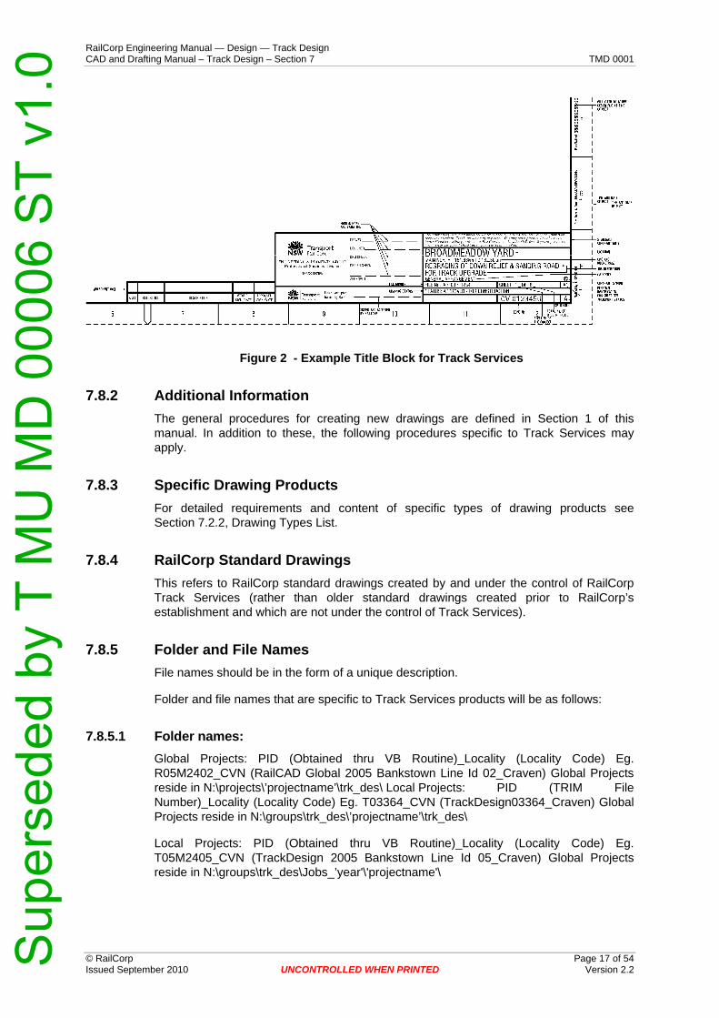
7.8.1 Title Blocks Setting out and filling in of the title block, signature block, amendment block and, if any, client title block, shall be in accordance with the sample shown in Figure 2.
For full details of RailCorp Title Blocks see Section 1.11.2 of this manual.
Sup
erse
ded
by T
MU
MD
000
06 S
T v1
.0
RailCorp Engineering Manual — Design — Track Design CAD and Drafting Manual – Track Design – Section 7 TMD 0001
Figure 2 - Example Title Block for Track Services
7.8.2 Additional Information The general procedures for creating new drawings are defined in Section 1 of this manual. In addition to these, the following procedures specific to Track Services may apply.
7.8.3 Specific Drawing Products For detailed requirements and content of specific types of drawing products see Section 7.2.2, Drawing Types List.
7.8.4 RailCorp Standard Drawings This refers to RailCorp standard drawings created by and under the control of RailCorp Track Services (rather than older standard drawings created prior to RailCorp’s establishment and which are not under the control of Track Services).
7.8.5 Folder and File Names File names should be in the form of a unique description.
Folder and file names that are specific to Track Services products will be as follows:
7.8.5.1 Folder names: Global Projects: PID (Obtained thru VB Routine)_Locality (Locality Code) Eg. R05M2402_CVN (RailCAD Global 2005 Bankstown Line Id 02_Craven) Global Projects reside in N:\projects\’projectname’\trk_des\ Local Projects: PID (TRIM File Number)_Locality (Locality Code) Eg. T03364_CVN (TrackDesign03364_Craven) Global Projects reside in N:\groups\trk_des\’projectname’\trk_des\
Local Projects: PID (Obtained thru VB Routine)_Locality (Locality Code) Eg. T05M2405_CVN (TrackDesign 2005 Bankstown Line Id 05_Craven) Global Projects reside in N:\groups\trk_des\Jobs_’year'\'projectname'\
© RailCorp Page 17 of 54 Issued September 2010 UNCONTROLLED WHEN PRINTED Version 2.2 Sup
erse
ded
by T
MU
MD
000
06 S
T v1
.0

RailCorp Engineering Manual — Design — Track Design CAD and Drafting Manual – Track Design – Section 7 TMD 0001
© RailCorp Page 18 of 54 Issued September 2010 UNCONTROLLED WHEN PRINTED Version 2.2
7.8.5.2 File names The convention should be PIDXXX (Type)_Version_Descriptive (as required).dg[n|m] Eg. T05M2405HAL_C1A_DM006.dgn (Bankstown Project 2005 Id 05 HorizontalAlignment_Concept Option 1 Ver A _ Down Main)
Sup
erse
ded
by T
MU
MD
000
06 S
T v1
.0
RailCorp Engineering Manual — Design — Track Design CAD and Drafting Manual – Track Design – Section 7 TMD 0001
© RailCorp Page 19 of 54 Issued September 2010 UNCONTROLLED WHEN PRINTED Version 2.2
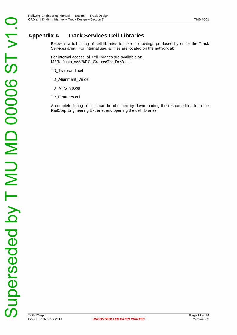
Appendix A Track Services Cell Libraries Below is a full listing of cell libraries for use in drawings produced by or for the Track Services area. For internal use, all files are located on the network at:
For internal access, all cell libraries are available at: M:\Rail\ustn_wsV8\RC_Groups\Trk_Des\cell.
TD_Trackwork.cel
TD_Alignment_V8.cel
TD_MTS_V8.cel
TP_Features.cel
A complete listing of cells can be obtained by down loading the resource files from the RailCorp Engineering Extranet and opening the cell libraries
Sup
erse
ded
by T
MU
MD
000
06 S
T v1
.0

RailCorp Engineering Manual — Design — Track Design CAD and Drafting Manual – Track Design – Section 7 TMD 0001
© RailCorp Page 20 of 54 Issued September 2010 UNCONTROLLED WHEN PRINTED Version 2.2
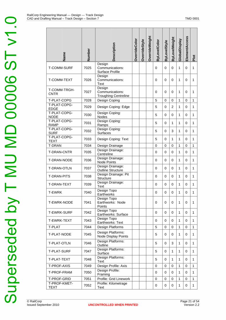
Appendix B Track Design Level Structure The MicroStation v8 levels for placement of various types of elements, Level Symbology Overrides and Symbology ByLevel shall be in accordance with the table on this and the following pages.
This level structure can be imported from the configuration resource directory: M:\Rail\ustn_wsV8\RC_Groups\Trk_Des\TD_Levels.dgnlib.
Nam
e
Num
ber
Des
crip
tion
Ove
rrid
eCol
or
Ove
rrid
eSty
le
Ove
rrid
eWei
ght
ByL
evel
Col
or
ByL
evel
Styl
e
ByL
evel
Wei
ght
Glo
balD
ispl
ay
Elem
entA
cces
s
Plot
T-CORD 7000 Annotation: Coordinates 0 0 1 1 0 1
T-LABL 7001 Annotation: Label 0 0 3 1 0 1 T-LEGD 7002 Annotation: Legend 0 0 1 1 0 1 T-NOTE 7003 Annotation: Notes 0 0 1 1 0 1
T-SCHD 7004 Annotation: Schedules 0 0 1 1 0 1
T-SYMB 7005 Annotation: Symbols (Marks) 0 0 1 1 0 1
T-TEXT-018 7006 Annotation: Text .18mm 0 0 0 1 0 1
T-TEXT-025 7007 Annotation: Text .25mm 0 0 1 1 0 1
T-TEXT-035 7008 Annotation: Text .35mm 0 0 2 1 0 1
T-TEXT-050 7009 Annotation: Text .5mm 0 0 3 1 0 1
T-TEXT-070 7010 Annotation: Text .7mm 0 0 4 1 0 1
T-TEXT-100 7011 Annotation: Text 1.0mm 0 0 5 1 0 1
T-BRDG 7012 Design Bridge 0 0 0 1 0 1
T-BRDG-DECK 7013 Design Bridge: Deck Details 0 0 0 1 0 1
T-BRDG-DECK-SURF 7014 Design Bridge: Deck
Surface 0 0 0 1 0 1
T-BRDG-NODE 7015 Design Bridge: Node Display Points 0 0 0 1 0 1
T-BRDG-TEXT 7016 Design Bridge: Text 0 0 0 1 0 1
T-BRDG-UNDR 7017 Design Bridge: Underside Details 0 0 0 1 0 1
T-BRDG-UNDR-SURF 7018 Design Bridge:
Underside Surface 0 0 0 1 0 1
T-CLER 7019 Clearance 0 0 0 1 0 1
T-CLER-DIMS 7020 Clearance: Dimensions 0 0 0 1 0 1
T-CLER-TEXT 7021 Clearance: Text 0 0 0 1 0 1
T-COMM 7022 Design Communications 0 0 0 1 0 1
T-COMM-NODE 7023 Design Communications: Node Display Points
0 0 0 1 0 1
T-COMM-STRC 7024 Design Communications: Structures
0 0 0 1 0 1
Sup
erse
ded
by T
MU
MD
000
06 S
T v1
.0
RailCorp Engineering Manual — Design — Track Design CAD and Drafting Manual – Track Design – Section 7 TMD 0001
© RailCorp Page 21 of 54 Issued September 2010 UNCONTROLLED WHEN PRINTED Version 2.2
Nam
e
Num
ber
Des
crip
tion
Ove
rrid
eCol
or
Ove
rrid
eSty
le
Ove
rrid
eWei
ght
ByL
evel
Col
or
ByL
evel
Styl
e
ByL
evel
Wei
ght
Glo
balD
ispl
ay
Elem
entA
cces
s
Plot
T-COMM-SURF 7025 Design Communications: Surface Profile
0 0 0 1 0 1
T-COMM-TEXT 7026 Design Communications: Text
0 0 0 1 0 1
T-COMM-TRGH-CNTR 7027
Design Communications: Troughing Centreline
0 0 0 1 0 1
T-PLAT-COPG 7028 Design Coping 5 0 0 1 0 1 T-PLAT-COPG-EDGE 7029 Design Coping: Edge 5 0 2 1 0 1
T-PLAT-COPG-NODE 7030 Design Coping:
Nodes 5 0 0 1 0 1
T-PLAT-COPG-RAMP 7031 Design Coping:
Ramps 5 0 1 1 0 1
T-PLAT-COPG-SURF 7032 Design Coping:
Surfaces 5 0 3 1 0 1
T-PLAT-COPG-TEXT 7033 Design Coping: Text 5 0 1 1 0 1
T-DRAN 7034 Design Drainage 0 0 0 1 0 1
T-DRAN-CNTR 7035 Design Drainage: Centreline 0 0 0 1 0 1
T-DRAN-NODE 7036 Design Drainage: Node Points 0 0 0 1 0 1
T-DRAN-OTLN 7037 Design Drainage: Outline Structure 0 0 0 1 0 1
T-DRAN-PITS 7038 Design Drainage: Pit Structure 0 0 0 1 0 1
T-DRAN-TEXT 7039 Design Drainage: Text 0 0 0 1 0 1
T-EWRK 7040 Design Topo Earthworks 0 0 0 1 0 1
T-EWRK-NODE 7041 Design Topo Earthworks: Node Points
0 0 0 1 0 1
T-EWRK-SURF 7042 Design Topo Earthworks: Surface 0 0 0 1 0 1
T-EWRK-TEXT 7043 Design Topo Earthworks: Text 0 0 0 1 0 1
T-PLAT 7044 Design Platforms 5 0 0 1 0 1
T-PLAT-NODE 7045 Design Platforms: Node Display Points 5 0 0 1 0 1
T-PLAT-OTLN 7046 Design Platforms: Outline 5 0 3 1 0 1
T-PLAT-SURF 7047 Design Platforms: Surface 5 0 1 1 0 1
T-PLAT-TEXT 7048 Design Platforms: Text 5 0 1 1 0 1
T-PROF-AXIS 7049 Design Profile: Axis 0 0 0 1 0 1
T-PROF-FRAM 7050 Design Profile: Framing 0 0 0 1 0 1
T-PROF-GRID 7051 Profile: Grid Linework 0 0 0 1 0 1 T-PROF-KMET-TEXT 7052 Profile: Kilometrage
Text 0 0 0 1 0 1
Sup
erse
ded
by T
MU
MD
000
06 S
T v1
.0

RailCorp Engineering Manual — Design — Track Design CAD and Drafting Manual – Track Design – Section 7 TMD 0001
© RailCorp Page 22 of 54 Issued September 2010 UNCONTROLLED WHEN PRINTED Version 2.2
Nam
e
Num
ber
Des
crip
tion
Ove
rrid
eCol
or
Ove
rrid
eSty
le
Ove
rrid
eWei
ght
ByL
evel
Col
or
ByL
evel
Styl
e
ByL
evel
Wei
ght
Glo
balD
ispl
ay
Elem
entA
cces
s
Plot
T-PROF-LABL 7053 Design Profile: Labels (Headings) 0 0 0 1 0 1
T-PROF-LINE 7054 Design Profile: Linework 0 0 0 1 0 1
T-PROF-TABL-FRAM 7055 Design Profile Table:
Frames 1 0 0 1 0 1
T-PROF-TABL-LABL 7056 Design Profile Table:
Labels 1 0 0 1 0 1
T-PROF-TABL-TEXT 7057 Design Profile Table:
Text 1 0 0 1 0 1
T-PROF-TEXT 7058 Design Profile: Annotation Text 0 0 0 1 0 1
T-TBED 7059 Design Trackbed 0 0 0 1 0 1
T-TBED-BLST 7060 Design Trackbed Ballast 0 0 0 1 0 1
T-TBED-BLST-NODE 7061 Design Trackbed
Ballast: Node Points 0 0 0 1 0 1
T-TBED-BLST-SURF 7062 Design Trackbed
Ballast: Surface 0 0 0 1 0 1
Default 0 Default 0 0 0 1 0 1 T-TBED-BLST-TEXT 7063 Design Trackbed
Ballast: Text 0 0 0 1 0 1
T-TBED-CAPG 7064 Design Trackbed Capping 0 0 0 1 0 1
T-TBED-CAPG-NODE 7065
Design Trackbed Capping: Node Points
0 0 0 1 0 1
T-TBED-CAPG-SURF 7066 Design Trackbed
Capping: Surface 0 0 0 1 0 1
T-TBED-CAPG-TEXT 7067 Design Trackbed
Capping: Layer Text 0 0 0 1 0 1
T-TRAK 7068 Design Trackwork 0 0 0 1 0 1
T-TRAK-ALGN 7069 Design Track Alignment 0 0 0 1 0 1
T-TRAK-ALGN-CARD 7070
Design Track Alignment: Cardinal Points (Symbols)
0 0 0 1 0 1
T-TRAK-ALGN-CLER 7071
Design Track Alignment: Clearance Point
0 0 0 1 0 1
T-TRAK-ALGN-CNST 7072
Design Track Alignment: Construction
0 0 0 1 0 1
T-TRAK-ALGN-CNTR 7073 Design Track
Alignment: Centreline 17 0 3 1 0 1
T-TRAK-ALGN-CORD-TEXT 7074
Design Track Alignment: Cardinal Coordinate Text
0 0 0 1 0 1
T-TRAK-ALGN-CPTS-SYMB 7075
Design Track Alignment: Catch Points Symbols
0 0 0 1 0 1
T-TRAK-ALGN-CPTS-TEXT 7076
Design Track Alignment: Catch Points Text
0 0 0 1 0 1
Sup
erse
ded
by T
MU
MD
000
06 S
T v1
.0

RailCorp Engineering Manual — Design — Track Design CAD and Drafting Manual – Track Design – Section 7 TMD 0001
© RailCorp Page 23 of 54 Issued September 2010 UNCONTROLLED WHEN PRINTED Version 2.2
Nam
e
Num
ber
Des
crip
tion
Ove
rrid
eCol
or
Ove
rrid
eSty
le
Ove
rrid
eWei
ght
ByL
evel
Col
or
ByL
evel
Styl
e
ByL
evel
Wei
ght
Glo
balD
ispl
ay
Elem
entA
cces
s
Plot
T-TRAK-ALGN-CURV-TEXT 7077
Design Track Alignment: Curve Text
197 0 0 1 0 1
T-TRAK-ALGN-DIMS 7078
Design Track Alignment: Dimensions
0 0 0 1 0 1
T-TRAK-ALGN-LABL 7079 Design Track
Alignment: Labels 197 0 2 1 0 1
T-TRAK-ALGN-NODE 7080
Design Track Alignment:Node (Construction Points)
0 0 0 1 0 1
T-TRAK-ALGN-SCHD 7081 Design Track
Alignment:Schedules 0 0 0 1 0 1
T-TRAK-ALGN-SUPR-TEXT 7082
Design Track Alignment: Super Elevation Text
0 0 0 1 0 1
T-TRAK-ALGN-SYMB 7083 Design Track
Alignment: Symbols 0 0 0 1 0 1
T-TRAK-ALGN-TEXT 7084 Design Track
Alignment: Text 0 0 0 1 0 1
T-TRAK-ALGN-VERT-TEXT 7085
Design Track Alignment: Vertical Alignment Text
197 0 0 1 0 1
T-TRAK-DIMS 7086 Design Trackworks: Dimensions 0 0 0 1 0 1
T-TRAK-KMET 7087 Design Track Kilometrage 0 0 0 1 0 1
T-TRAK-KMET-ADJS-TEXT 7088
Design Kilometrage: Adjustment Text / Details
192 0 0 1 0 1
T-TRAK-KMET-CARD-LABL 7089
Design Kilometrage: Alignment Cardinal Labels (TP,TRS)
1 0 0 1 0 1
T-TRAK-KMET-MAJR-TEXT 7090 Design Kilometrage:
Major Text / Ticks 192 0 0 1 0 1
T-TRAK-KMET-MINR-TEXT 7091 Design Kilometrage:
Minor Text / Ticks 192 0 0 1 0 1
T-TRAK-KMET-MISC-TEXT 7092
Design Kilometrage: Miscellaneous Text / Details
192 0 0 1 0 1
T-TRAK-RAIL 7093 Design Track Rails 0 0 0 1 0 1 T-TRAK-RAIL-CHCK 7094 Design Track Rails:
Check Rail 0 0 0 1 0 1
T-TRAK-RAIL-CLIP 7095 Design Track Rails: Clip Components 0 0 0 1 0 1
T-TRAK-RAIL-CNTR 7096 Design Track Rails:
Centerline 17 4 0 1 0 1
T-TRAK-RAIL-DIMS 7097 Design Track Rails: Dimensions 0 0 0 1 0 1
T-TRAK-RAIL-FACE 7098 Design Track Rails:
Running Face of Rail 17 0 0 1 0 1
T-TRAK-RAIL-FOOT 7099 Design Track Rails:
Foot 75 0 0 1 0 1
T-TRAK-RAIL-HEAD 7100 Design Track Rails:
Head 52 0 0 1 0 1
Sup
erse
ded
by T
MU
MD
000
06 S
T v1
.0

RailCorp Engineering Manual — Design — Track Design CAD and Drafting Manual – Track Design – Section 7 TMD 0001
© RailCorp Page 24 of 54 Issued September 2010 UNCONTROLLED WHEN PRINTED Version 2.2
Nam
e
Num
ber
Des
crip
tion
Ove
rrid
eCol
or
Ove
rrid
eSty
le
Ove
rrid
eWei
ght
ByL
evel
Col
or
ByL
evel
Styl
e
ByL
evel
Wei
ght
Glo
balD
ispl
ay
Elem
entA
cces
s
Plot
T-TRAK-RAIL-LABL 7101 Design Track Rails: Labels 0 0 0 1 0 1
T-TRAK-RAIL-NODE 7102 Design Track Rails:
Node Points 0 0 0 1 0 1
T-TRAK-RAIL-PLTS 7103 Design Track Rails: Plate Components 0 0 0 1 0 1
T-TRAK-RAIL-SYMB 7104 Design Track Rails:
Symbols 0 0 0 1 0 1
T-TRAK-RAIL-TEXT 7105 Design Track Rails: Text 0 0 0 1 0 1
T-TRAK-SLPR 7106 Design Track Sleepers 0 0 0 1 0 1
T-TRAK-SLPR-CNTR 7107 Design Track
Sleepers: Centreline 0 0 0 1 0 1
T-TRAK-SLPR-OTLN 7108 Design Track
Sleepers: Outline 0 0 0 1 0 1
T-TRAK-SLPR-TEXT 7109 Design Track
Sleepers: Text 0 0 0 1 0 1
T-TRAK-STRC 7110 Design Track Structures 0 0 0 1 0 1
T-TRAK-STRC-CNTR 7111
Design Track Structures: Centreline
0 0 0 1 0 1
T-TRAK-STRC-NODE 7112
Design Track Structures: Node Points
0 0 0 1 0 1
T-TRAK-STRC-OTLN 7113 Design Track
Structures: Outline 0 0 0 1 0 1
T-TRAK-STRC-TEXT 7114 Design Track
Structures: Text 0 0 0 1 0 1
T-TRAK-TEXT 7115 Design Track Text 0 0 0 1 0 1
T-TRAK-TEXT-CARD 7116
Design Track Text: Cardinals (Frame Point)
0 0 0 1 0 1
T-TRAK-TEXT-CURV 7117 Design Track Text:
Curve Details 0 0 0 1 0 1
T-TRAK-TEXT-DIMS 7118
Design Track Text: Dimensions (Radius, Arc etc)
0 0 0 1 0 1
T-TRAK-TEXT-KMAJ 7119
Design Track Text: Kilometrage Adjustments
0 0 0 1 0 1
T-TRAK-TEXT-LABL 7120
Design Track Text: Track Labels (Names)
0 0 0 1 0 1
T-TRAK-TEXT-MAJR 7121 Design Track Text:
Major Metrages 0 0 0 1 0 1
T-TRAK-TEXT-MINR 7122 Design Track Text:
Minor Metrages 0 0 0 1 0 1
T-TRNO 7123 Design Turnouts 0 0 0 1 0 1
T-TRNO-BEAM 7124 Design Turnouts: Beams 0 0 0 1 0 1
T-TRNO-BEAM-CNTR 7125 Design Turnouts:
Beam CL 0 0 0 1 0 1
Sup
erse
ded
by T
MU
MD
000
06 S
T v1
.0

RailCorp Engineering Manual — Design — Track Design CAD and Drafting Manual – Track Design – Section 7 TMD 0001
© RailCorp Page 25 of 54 Issued September 2010 UNCONTROLLED WHEN PRINTED Version 2.2
Nam
e
Num
ber
Des
crip
tion
Ove
rrid
eCol
or
Ove
rrid
eSty
le
Ove
rrid
eWei
ght
ByL
evel
Col
or
ByL
evel
Styl
e
ByL
evel
Wei
ght
Glo
balD
ispl
ay
Elem
entA
cces
s
Plot
T-TRNO-CNST 7126 Design Turnouts: Construction Works 0 0 0 1 0 1
T-TRNO-CPTS 7127 Design Turnouts: Construction Works - Active Points
0 0 0 1 0 1
T-TRNO-DIMS 7128 Design Turnouts: Dimensions 0 0 0 1 0 1
T-TRNO-LABL 7129 Design Turnouts: Text Labels 0 0 0 1 0 1
T-TRNO-NODE 7130 Design Turnouts: Node Points 0 0 0 1 0 1
T-TRNO-NODE-SYMB 7131 Design Turnouts:
Node Symbols 0 0 0 1 0 1
T-TRNO-NOTE 7132 Design Turnouts: Notes 0 0 0 1 0 1
T-TRNO-SYMB 7133 Design Turnouts: Symbols 0 0 0 1 0 1
T-TRNO-TEXT 7134 Design Turnouts: Text 0 0 0 1 0 1
T-TUNL 7135 Design Tunnels 0 0 0 1 0 1
T-TUNL-CNTR 7136 Design Tunnels: Centreline 0 0 0 1 0 1
T-TUNL-NODE 7137 Design Tunnels: Node Points 0 0 0 1 0 1
T-TUNL-OTLN 7138 Design Tunnels: Outline Structure 0 0 0 1 0 1
T-TUNL-SURF 7139 Design Tunnels: Surface 0 0 0 1 0 1
T-TUNL-TEXT 7140 Design Tunnels: Text 0 0 0 1 0 1
T-KINE-CNST 7141 Kinematic: Construction Lines 0 0 0 1 0 1
T-KINE-PANT-CLER 7142
Kinematic: Pantograph Clearance
0 0 0 1 0 1
T-KINE-PANT-OUTL 7143 Kinematic:
Pantograph Outiline 0 0 0 1 0 1
T-KINE-ROLL-CLER 7144
Kinematic: Rollingstock Clearance
0 0 0 1 0 1
T-KINE-ROLL-OUTL 7145 Kinematic:
Rollingstock Outline 0 0 0 1 0 1
T-KINE-TEXT 7146 Kinematic: Text 0 0 0 1 0 1
T-TRAK-RAIL-DN 7147 Design Track: Rail Down Running Face 3 0 0 1 0 1
T-TRAK-RAIL-UP 7148 Design Track: Rail Up Running Face 3 0 0 1 0 1
T-PLAT-LABL 7149 Design Platform: Label 5 0 3 1 0 1
T-TRNO-RAIL-CNTR 7150 Design Turnouts:
Rail centreline 0 0 0 0 0 1
T-TRNO-RAIL-HEAD 7151 Design Turnouts:
Rail head 0 0 0 0 0 1
T-TRNO-RAIL-FOOT 7152 Design Turnouts:
Rail foot 0 0 0 0 0 1
Sup
erse
ded
by T
MU
MD
000
06 S
T v1
.0
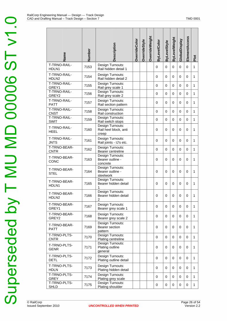
RailCorp Engineering Manual — Design — Track Design CAD and Drafting Manual – Track Design – Section 7 TMD 0001
© RailCorp Page 26 of 54 Issued September 2010 UNCONTROLLED WHEN PRINTED Version 2.2
Nam
e
Num
ber
Des
crip
tion
Ove
rrid
eCol
or
Ove
rrid
eSty
le
Ove
rrid
eWei
ght
ByL
evel
Col
or
ByL
evel
Styl
e
ByL
evel
Wei
ght
Glo
balD
ispl
ay
Elem
entA
cces
s
Plot
T-TRNO-RAIL-HDLN1 7153 Design Turnouts:
Rail hidden detail 1 0 0 0 0 0 1
T-TRNO-RAIL-HDLN2 7154 Design Turnouts:
Rail hidden detail 2 0 0 0 0 0 1
T-TRNO-RAIL-GREY1 7155 Design Turnouts:
Rail grey scale 1 0 0 0 0 0 1
T-TRNO-RAIL-GREY2 7156 Design Turnouts:
Rail grey scale 2 0 0 0 0 0 1
T-TRNO-RAIL-PATT 7157 Design Turnouts:
Rail section pattern 0 0 0 0 0 1
T-TRNO-RAIL-CNST 7158 Design Turnouts:
Rail construction 0 0 0 0 0 1
T-TRNO-RAIL-SWIT 7159 Design Turnouts:
Rail switch stops 0 0 0 0 0 1
T-TRNO-RAIL-HEEL 7160
Design Turnouts: Rail heel block, anti creep
0 0 0 0 0 1
T-TRNO-RAIL-JNTS 7161 Design Turnouts:
Rail joints - IJ's etc. 0 0 0 0 0 1
T-TRNO-BEAR-CNTR 7162 Design Turnouts:
Bearer centreline 0 0 0 0 0 1
T-TRNO-BEAR-CONC 7163
Design Turnouts: Bearer outline - concrete
0 0 0 0 0 1
T-TRNO-BEAR-STEL 7164
Design Turnouts: Bearer outline - steelwork
0 0 0 0 0 1
T-TRNO-BEAR-HDLN1 7165
Design Turnouts: Bearer hidden detail 1
0 0 0 0 0 1
T-TRNO-BEAR-HDLN2 7166
Design Turnouts: Bearer hidden detail 2
0 0 0 0 0 1
T-TRNO-BEAR-GREY1 7167 Design Turnouts:
Bearer grey scale 1 0 0 0 0 0 1
T-TRNO-BEAR-GREY2 7168 Design Turnouts:
Bearer grey scale 2 0 0 0 0 0 1
T-TRNO-BEAR-PATT 7169
Design Turnouts: Bearer section pattern
0 0 0 0 0 1
T-TRNO-PLTS-CNTR 7170 Design Turnouts:
Plating centreline 0 0 0 0 0 1
T-TRNO-PLTS-GENR 7171
Design Turnouts: Plating outline general
0 0 0 0 0 1
T-TRNO-PLTS-DETL 7172 Design Turnouts:
Plating outline detail 0 0 0 0 0 1
T-TRNO-PLTS-HDLN 7173 Design Turnouts:
Plating hidden detail 0 0 0 0 0 1
T-TRNO-PLTS-GREY 7174 Design Turnouts:
Plating grey scale 0 0 0 0 0 1
T-TRNO-PLTS-SHLD 7175 Design Turnouts:
Plating shoulder 0 0 0 0 0 1
Sup
erse
ded
by T
MU
MD
000
06 S
T v1
.0

RailCorp Engineering Manual — Design — Track Design CAD and Drafting Manual – Track Design – Section 7 TMD 0001
© RailCorp Page 27 of 54 Issued September 2010 2.2 UNCONTROLLED WHEN PRINTED Version
Nam
e
Num
ber
Des
crip
tion
Ove
rrid
eCol
or
Ove
rrid
eSty
le
Ove
rrid
eWei
ght
ByL
evel
Col
or
ByL
evel
Styl
e
ByL
evel
Wei
ght
Glo
balD
ispl
ay
Elem
entA
cces
s
Plot
T-TRNO-PLTS-BRAC 7176 Design Turnouts:
Plating rail brace 0 0 0 0 0 1
T-TRNO-PLTS-BOLT 7177 Design Turnouts:
Plating bolts 0 0 0 0 0 1
T-TRNO-PLTS-SPIK 7178 Design Turnouts:
Plating screwspikes 0 0 0 0 0 1
T-TRNO-TEXT-LABL 7179 Design Turnouts:
Labels 0 0 0 0 0 1
T-TRNO-TEXT-NOTE 7180 Design Turnouts:
Notes 0 0 0 0 0 1
T-TRNO-TEXT-GENR 7181 Design Turnouts:
General 0 0 0 0 0 1
T-TRNO-TEXT-TABL 7182 Design Turnouts:
Tables 0 0 0 0 0 1
T-TRNO-TEXT-HEAD-35 7183 Design Turnouts:
Headings - small 0 0 0 0 0 1
T-TRNO-TEXT-HEAD-50 7184 Design Turnouts:
Headings - medium 0 0 0 0 0 1
T-TRNO-TEXT-HEAD-70 7185 Design Turnouts:
Headings - large 0 0 0 0 0 1
T-TRNO-TEXT-DIMS 7186 Design Turnouts:
Dimensioning 0 0 0 0 0 1
T-TRNO-MISC-CNST 7187 Design Turnouts:
Construction lines 0 0 0 0 0 1
T-TRNO-MISC-CPTS 7188 Design Turnouts:
Construction points 0 0 0 0 0 1
T-TRNO-MISC-SETT 7189 Design Turnouts:
Setting out diagrams 0 0 0 0 0 1
T-TRNO-MISC-CNTR 7190 Design Turnouts:
Track centreline 0 0 0 0 0 1
T-TRNO-MISC-REFP 7191
Design Turnouts: Track reference points
0 0 0 0 0 1
Sup
erse
ded
by T
MU
MD
000
06 S
T v1
.0

ering Manual — Design — Track Design rafting Manual – Track Design – Section 7 TMD 0001
© RailCorp Page 28 of 54 Issued September 2010 Version 2.2
UNCONTROLLED WHEN PRINTED
Appendix C Plan Presentation – Horizontal Alignment Design
RailCorp EngineCAD and D
Sup
erse
ded
by T
MU
MD
000
06 S
T v1
.0
RailCorp Engineering Manual — Design — Track Design CAD and Drafting Manual – Track Design – Section 7 TMD 0001
Figure A3-1
Figure A3-2
Figure A3-3
Figure A3-4
Figure A3-5
Figure A3-6
Figure A3-7
© RailCorp Page 29 of 54 Issued September 2010 UNCONTROLLED WHEN PRINTED Version 2.2 Sup
erse
ded
by T
MU
MD
000
06 S
T v1
.0

RailCorp Engineering Manual — Design — Track Design CAD and Drafting Manual – Track Design – Section 7 TMD 0001
© RailCorp Page 30 of 54 Issued September 2010 2.2 UNCONTROLLED WHEN PRINTED Version
Figure A3-8
Figure A3-9
Figure A3-10
Figure A3-11
Figure A3-12
Figure A3-13
Figure A3-15
Figure A3-14
Sup
erse
ded
by T
MU
MD
000
06 S
T v1
.0

ering Manual — Design — Track Design rafting Manual – Track Design – Section 7 TMD 0001
© RailCorp Page 31 of 54 Issued September 2010 Version 2.2
UNCONTROLLED WHEN PRINTED
Appendix D Plan Presentation – Track Setting Out Details
RailCorp EngineCAD and D
Sup
erse
ded
by T
MU
MD
000
06 S
T v1
.0

RailCorp Engineering Manual — Design — Track Design CAD and Drafting Manual – Track Design – Section 7 TMD 0001
Figure A4-1
Figure A4-2
Figure A4-3
Figure A4-4
Figure A4-5
Figure A4-9
Figure A4-6
© RailCorp Page 32 of 54 Issued September 2010 UNCONTROLLED WHEN PRINTED Version 2.2 Sup
erse
ded
by T
MU
MD
000
06 S
T v1
.0

RailCorp Engineering Manual — Design — Track Design CAD and Drafting Manual – Track Design – Section 7 TMD 0001
© RailCorp Page 33 of 54 Issued September 2010 2.2
UNCONTROLLED WHEN PRINTED Version
Figure A4-7
Figure A4-8
Figure A4-10
Figure A4-11
Figure A4-14
Figure A4-15
Figure A4-12
Figure A4-13
Figure A4-16
Sup
erse
ded
by T
MU
MD
000
06 S
T v1
.0

ering Manual — Design — Track Design rafting Manual – Track Design – Section 7 TMD 0001
© RailCorp Page 34 of 54 Issued September 2010 Version 2.2 UNCONTROLLED WHEN PRINTED
Appendix E Plan Presentation – Vertical Alignment Design
RailCorp EngineCAD and D
Sup
erse
ded
by T
MU
MD
000
06 S
T v1
.0

RailCorp Engineering Manual — Design — Track Design CAD and Drafting Manual – Track Design – Section 7 TMD 0001
Figure A5-1
Figure A5-2
Figure A5-3
Figure A5-4
Figure A5-5
Figure A5-6
Figure A5-7
Figure A5-8
Figure A5-9
Figure A5-10
Figure A5-18
Figure A5-11
© RailCorp Page 35 of 54 Issued September 2010 UNCONTROLLED WHEN PRINTED Version 2.2 Sup
erse
ded
by T
MU
MD
000
06 S
T v1
.0

RailCorp Engineering Manual — Design — Track Design CAD and Drafting Manual – Track Design – Section 7 TMD 0001
© RailCorp Page 36 of 54 Issued September 2010 2.2
Figure A5-12
Figure A5-13
Figure A5-14
Figure A5-15
Figure A5-16
Figure A5-17
UNCONTROLLED WHEN PRINTED Version Sup
erse
ded
by T
MU
MD
000
06 S
T v1
.0
ering Manual — Design — Track Design rafting Manual – Track Design – Section 7 TMD 0001
© RailCorp Page 37 of 54 Issued September 2010 Version 2.2
Appendix F Plan Presentation – Field Layout for Tangential Turnouts
UNCONTROLLED WHEN PRINTED
RailCorp EngineCAD and D
Sup
erse
ded
by T
MU
MD
000
06 S
T v1
.0

RailCorp Engineering Manual — Design — Track Design CAD and Drafting Manual – Track Design – Section 7 TMD 0001
Figure A6-1
Figure A6-2
Figure A6-3
Figure A6-5
Figure A6-4 Figure A6-6
© RailCorp Page 38 of 54 Issued September 2010 UNCONTROLLED WHEN PRINTED Version 2.2 Sup
erse
ded
by T
MU
MD
000
06 S
T v1
.0

RailCorp Engineering Manual — Design — Track Design CAD and Drafting Manual – Track Design – Section 7 TMD 0001
© RailCorp Page 39 of 54 Issued September 2010 2.2
Figure A6-7
UNCONTROLLED WHEN PRINTED Version
Figure A6-9
Figure A6-8
Sup
erse
ded
by T
MU
MD
000
06 S
T v1
.0

ering Manual — Design — Track Design rafting Manual – Track Design – Section 7 TMD 0001
© RailCorp Page 40 of 54 Issued September 2010 Version 2.2
Appendix G Plan Presentation – Tie layout and details for Tangential Turnouts
UNCONTROLLED WHEN PRINTED
RailCorp EngineCAD and D
Sup
erse
ded
by T
MU
MD
000
06 S
T v1
.0
RailCorp Engineering Manual — Design — Track Design CAD and Drafting Manual – Track Design – Section 7 TMD 0001
Figure A7-1
Figure A7-2
Figure A7-3
Figure A7-4
Figure A7-5
Figure A7-6
© RailCorp Page 41 of 54 Issued September 2010 UNCONTROLLED WHEN PRINTED Version 2.2 Sup
erse
ded
by T
MU
MD
000
06 S
T v1
.0

RailCorp Engineering Manual — Design — Track Design CAD and Drafting Manual – Track Design – Section 7 TMD 0001
© RailCorp Page 42 of 54 Issued September 2010 2.2
UNCONTROLLED WHEN PRINTED Version
Figure A7-8
Figure A7-7
Figure A7-9
Sup
erse
ded
by T
MU
MD
000
06 S
T v1
.0

ering Manual — Design — Track Design rafting Manual – Track Design – Section 7 TMD 0001
© RailCorp Page 43 of 54 Issued September 2010 Version 2.2
Appendix H Plan Presentation – Timber & Plating for Conventional Turnouts
UNCONTROLLED WHEN PRINTED
RailCorp EngineCAD and D
Sup
erse
ded
by T
MU
MD
000
06 S
T v1
.0

RailCorp Engineering Manual — Design — Track Design CAD and Drafting Manual – Track Design – Section 7 TMD 0001
Figure A8-1
Figure A8-3
Figure A8-2
© RailCorp Page 44 of 54 Issued September 2010 UNCONTROLLED WHEN PRINTED Version 2.2 Sup
erse
ded
by T
MU
MD
000
06 S
T v1
.0

RailCorp Engineering Manual — Design — Track Design CAD and Drafting Manual – Track Design – Section 7 TMD 0001
Figure A8-5
Figure A8-4
Figure A8-6
Figure A8-7
Figure A8-8
Figure A8-9
Figure A8-9
© RailCorp Page 45 of 54 Issued September 2010 UNCONTROLLED WHEN PRINTED Version 2.2 Sup
erse
ded
by T
MU
MD
000
06 S
T v1
.0

RailCorp Engineering Manual — Design — Track Design CAD and Drafting Manual – Track Design – Section 7 TMD 0001
© RailCorp Page 46 of 54 Issued September 2010 2.2
UNCONTROLLED WHEN PRINTED Version
Figure A8-10
Sup
erse
ded
by T
MU
MD
000
06 S
T v1
.0

RailCorp Engineering Manual — Design — Track Design CAD and Drafting Manual – Track Design – Section 7 TMD 0001
Appendix I Plan Presentation – Detail Survey Drawing
© RailCorp Page 47 of 54 Issued September 2010 UNCONTROLLED WHEN PRINTED Version 2.2
Figure 3
Sup
erse
ded
by T
MU
MD
000
06 S
T v1
.0

RailCorp Engineering Manual — Design — Track Design CAD and Drafting Manual – Track Design – Section 7 TMD 0001
Figure 4
© RailCorp Page 48 of 54 Issued September 2010 UNCONTROLLED WHEN PRINTED Version 2.2 S
uper
sede
d by
T M
U M
D 0
0006
ST
v1.0

RailCorp Engineering Manual — Design — Track Design CAD and Drafting Manual – Track Design – Section 7 TMD 0001
Figure 5
© RailCorp Page 49 of 54 Issued September 2010 UNCONTROLLED WHEN PRINTED Version 2.2 S
uper
sede
d by
T M
U M
D 0
0006
ST
v1.0
RailCorp Engineering Manual — Design — Track Design CAD and Drafting Manual – Track Design – Section 7 TMD 0001
Figure 6
© RailCorp Page 50 of 54 Issued September 2010 UNCONTROLLED WHEN PRINTED Version 2.2 S
uper
sede
d by
T M
U M
D 0
0006
ST
v1.0

RailCorp Engineering Manual — Design — Track Design CAD and Drafting Manual – Track Design – Section 7 TMD 0001
Appendix J Plan Presentation – Cross Section Drawing
Figure 7
© RailCorp Page 51 of 54 Issued September 2010 UNCONTROLLED WHEN PRINTED Version 2.2 S
uper
sede
d by
T M
U M
D 0
0006
ST
v1.0

RailCorp Engineering Manual — Design — Track Design CAD and Drafting Manual – Track Design – Section 7 TMD 0001
Figure 8
© RailCorp Page 52 of 54 Issued September 2010 UNCONTROLLED WHEN PRINTED Version 2.2 S
uper
sede
d by
T M
U M
D 0
0006
ST
v1.0

RailCorp Engineering Manual — Design — Track Design CAD and Drafting Manual – Track Design – Section 7 TMD 0001
Figure 9
© RailCorp Page 53 of 54 Issued September 2010 UNCONTROLLED WHEN PRINTED Version 2.2 S
uper
sede
d by
T M
U M
D 0
0006
ST
v1.0
RailCorp Engineering Manual — Design — Track Design CAD and Drafting Manual – Track Design – Section 7 TMD 0001
Figure 10
© RailCorp Page 54 of 54 Issued September 2010 UNCONTROLLED WHEN PRINTED Version 2.2 S
uper
sede
d by
T M
U M
D 0
0006
ST
v1.0