technical information rf module for sending audio signal ... · rf module for sending audio signal...
TRANSCRIPT

TECHNICAL INFORMATION
TI_003_v10e CIRCUIT DESIGN, INC.
March 2001
RF Module for sending audio signal in the new European 863-865MHz band with quality of professional wireless microphone system - Its technical feature -
By Yukinaga Koike, Circuit Design, Inc.
Circuit Design, Inc. has been developed and manufactured wireless microphone systems for professional use for the past 20 years. When the frequency range of 863 to 865MHz was newly allocated to audio applications in Europe, we had an idea of designing a full-fledged wireless audio module (WA-TX-01 and WA-RX-01) with maintaining the quality, which is an essential requirement for wireless microphone system, utilizing the know-how accumulated through the development of the professional wireless microphone systems. We assume this kind of small, versatile and built-in type wireless audio module with a wide dynamic range had not been marketed before. Here we will introduce the product and its technology, expecting it can provide new concept to the audio equipment industry and its low power radio technology will be employed more readily in a variety of audio applications. The WA-TX-01 and the WA-RX-01 include the components, such as SAW filters, SAW resonators and noise reduction ICs, which were developed for a super-compact wireless microphone system Circuit Design Inc. designed and succeeded in introducing into the market recently. These key devices enabled to design a small and high quality audio module, WA-TX-01 and the WA-RX-01, allowing audio equipment manufactures, who do not have a good knowledge of radio technique, to make high-value added products using radio. The TX and RX modules are scheduled to be certified to European radio regulations and EMC standard under R&TTE Directive. Since the procedure for getting the compliance certificate is very complicated and requires cost and time, the audio equipment company and audio equipment installation company whose project dose not require large volume production might have hesitated to make their systems wireless. However by using this licence exempt product in their applications, their own the wireless systems can be completed easily without bothersome and costly certification procedures. The operating frequency channel for each module is fixed. However 4 channels are available in the range of 863-865MHz with 4 different modules, so that multiple systems can be operated at the same location. Also as the module itself is very compact and its replacement can be done easily in the user’s device, operating channel can be changed only by reinstalling the modules with different channel. For receiving systems requiring more reliable communication, the WA-RX-02 receiver, which employed diversity reception technology to reduce a dead point problem due to multi-path effect, is added in the product line up. Also the DC/DC converter which enables to operate the transmitter with only one 1.5V battery is prepared as an optional accessory for the application pursuing miniaturization. We would like to support the users by releasing the peripheral circuits and PCB pattern example which must be designed by users in the Circuit Design’s web site http://www.circuitdesign.co.jp/ and encourage a widespread use of this kind of products. The wireless audio transmission technology in the 863-865MHz band will be outlined below, explaining the circuitry technologies adopted in the WA-TX-01 and the WA-RX-01.

TECHNICAL INFORMATION
TI_003_v10e CIRCUIT DESIGN, INC.
March 2001
Audio transmission with wide dynamic range It is generally known that the maximum audible sound pressure of a human being would be 140dBSPL. The
sound pressure level mentioned here is calculated based on ‘the minimum audible sound pressure 0dBSPL =
20 upa’.
Even in a quiet room, there exists a background noise of approximately 20dBSPL *1.
And the sound pressure of a human loud voice is about 120dBSPL. So it can be said that the sound pressure
level required for usual wireless audio transmission is 100dB, which is given by subtracting 20dBSPL from
120dBSPL.
*1 SPL= a unit for sound pressure level
Barrier of Radio Law (Radio regulations) Every country has strict regulations for the use of frequency and bandwidth, to utilize the limited radio resources
efficiently. In general, when an audible frequency of 15kHz is analog-frequency modulated, the occupied
bandwidth will equal to ‘(Maximum frequency deviation + highest modulation frequency) x 2’.
Let’s consider the bandwidth required for transmitting an audio signal, which has 100dB of dynamic range, using
FM*2. It is assumed that an FM circuit is configured with a variable capacitor, which is used for modulation,
connected to a reference crystal oscillation circuit. A crystal itself is an accurate oscillation source. However since
other components, such as a transistor for oscillation and a variable capacitor used for modulation, produce
noise. Therefore you will see that there exists a residual FM noise of 50Hz with no modulation, even though
being measured using a cut-off-low pass filter of 20kHz.
A PLL circuit, in which an LC oscillation circuit is phase locked to a crystal oscillator, will have more residual FM
noise. *2 FM = Frequency Modulation
Now let’s get back to the calculation of the occupied bandwidth when transmitting a sound signal which requires
100dB of dynamic range. A gain of 20dB equals to ten-fold, and as a gain is increased or reduced logarithmically,
that is a gain of 100dB is equal to hundred-thousand-fold. Provided that there is 50Hz of residual FM noise, this
dynamic range of 100dB will require a frequency deviation of 5MHz.
Then the occupied bandwidth you can get by using the above formula will become tremendously wide and you
may conclude it is impossible to transmit 100dB of dynamic range by radio.
Noise reduction system To resolve this problem and meet the frequency deviation requirement specified in radio laws, standard wireless
microphone systems use a compressor in the transmitter and an expander in the receiver. This method is known
as ‘compandor noise reduction system’ (See figure 1).
With a Dolby system, which is widely known as a noise reduction system, a compression ratio will vary in
accordance with the frequency change of an audio signal. On the other hand, with a compander noise reduction
system, the whole frequency range will be compressed to half at a ratio of 2:1 by a compressor and then, in an
exactly opposite way, expanded double at a 1:2 ratio by an expander.

TECHNICAL INFORMATION
TI_003_v10e CIRCUIT DESIGN, INC.
March 2001
Noise reduction effect 100dB of dynamic range becomes 50dB by
being compressed at a ratio of 2:1 (See
figure 2).
Now you can calculate the frequency
deviation as before. Considering 50Hz of
residual FM noise, you can start with
20dB=500Hz, then 40dB=5kHz, and then
you will get 52dB equals to 20kHz. At this
time you will conclude that it is possible to
transmit 50dB of dynamic range with a
frequency deviation of less than 20kHz.
In other words, the wireless system with
50dB of S/N (Signal to Noise ratio) can
transmit sound pressure which has 100dB of
dynamic range.
Fig.1
Fig.2

TECHNICAL INFORMATION
TI_003_v10e CIRCUIT DESIGN, INC.
March 2001
Why is analog transmission used for a wireless microphone system? Sound transmission systems such as satellite broadcasting transmit voice sounds with PCM. So why
use analog transmission for a wireless microphone system?
There may be the following 4 reasons;
. Many countries do not have a frequency band allocated exclusively for digital wireless microphone systems.
. Digital transmission systems such as PCM use a wide frequency range and its utilization is not easy in the
frequency range below 1GHz.
. In the frequency range above 1GHz, dead spots occur frequently with slight movements. This means such a
frequency range is not suitable for wireless microphone systems intended for the use at live stage performances
involving many movements of position.
. If digital conversion is done in the transmitter part, power consumption will become very high. As a result, it will
be difficult to make a system operated with small batteries.
This situation will last until the radio regulations are reviewed and the current consumption of the A/D converter,
DSP and multi-valued modulation circuit is drastically reduced.
Operating frequency plan In case some wireless microphone systems are operated at one time with frequency division method in the same
area, a frequency plan to be used for the operation is important.
When transmitting signals with analog FM, if more than 3 frequencies are transmitted with the same frequency
span, interference always happens. Interference reduces the acoustic fidelity extremely with a beat sound. This
is caused by the intermodulation made in the non-linear part of the receiver and this phenomenon is called third
Fig.3

TECHNICAL INFORMATION
TI_003_v10e CIRCUIT DESIGN, INC.
March 2001
intermodulation (see fig 3). To avoid this problem, a frequency channel plan applied to wireless microphone
systems dose not have equal frequency spans between channels, without using the frequency channels where
the third intermodulation may occur.
Necessity of diversity reception Usually dead spots due to multiple transmission paths occur frequently at intervals of 1/2 lambda. In addition, if
there are metal objects in the operating area, dead spots will occur more often due to reflections off the metal
objects. If the range between the transmitter and the receiver is more than 50m, diversity reception systems will
reduce this problem. In case of wireless data transmission, if a packet error occurs, resend requests and antenna
switching between the diversity antennas spaced 1/4 lambda can be performed, and the time delay caused by
this procedure will not be any big problem. However as for wireless microphone systems, real-time operation is
an important factor and even 10msec of delay will not be accepted.
The diversity technology for a wireless microphone uses two discrete receivers, each with its own antenna,
simultaneously. The two antennas must be kept 1/4 lambda apart. The field strengths from the two receivers will
be compared by a comparator to select the receiver with a higher field strength and then switching of the
demodulated analog signal will be done by an analog switch (see fig.4).
Low noise DC/DC converter A low noise DC/DC converter enables you to operate the transmitter and receiver modules, which require 3V of
supply voltage, using one battery of 1.5V. Generally DC/DC converters are classified into two types, frequency
variable type and frequency fixed type. For wireless systems, the frequency fixed type is used as a power source
since it is easy to make measures against noise. In addition, a filter is used in the output stage to reduce noise.
Fig.4

TECHNICAL INFORMATION
TI_003_v10e CIRCUIT DESIGN, INC.
March 2001
To achieve an overall 100dB of dynamic range in wireless microphone systems, residual noise of the DC/DC
converter must be less than –60dBm.
The minimum operating voltage of the DC/DC converter is 0.9 V and the secondary side voltage is 3 V and the
maximum load current is 50mA.
WA-TX-01 transmitter
Input buffer This circuit is an input buffer circuit for the microphone unit and other audio signal sources. The maximum input
level is –10dBv and the input impedance is 7.5 kohm.
If the maximum output level of the signal sources is not large enough, a low noise amplifier must be inserted in
the previous stage. If the output level is too large, an attenuator must be used.
Compressor The audio signal from the buffer circuit will be compressed to half at a ratio of 2:1. (see equivalent circuit). This
circuit is configured with a reference power supply circuit, a full-wave rectification circuit, a current control rectifier
and a summing amplifier.
The reference power supply circuit provides bias voltage and constant current to each part of the circuit.
Fig.5
TECHNICAL INFORMATION
TI_003_v10e CIRCUIT DESIGN, INC.
March 2001
The full-wave rectification circuit will full-wave rectify the incoming signal and then smooth the rectified signal
using external capacity. The outputted current will be control current for the gain cell amplifier.
The smoothing capacity also decides the time constant of the compander, multiplying its value by internal
resistance (R=10 kohm).
The output current (Irect) is given by;
Irect=Vin(av)/Rin x n
Rin=20 kohm, Vin(av)=Avelage value, n=4 (Gain of internal Tr)
Gain Cell The gain cell amplifies the incoming signal by controlling the gain with the control current from the full-wave
rectifier and output current.
The output current is given by;
Iout=(Vin/Rin x Io) x Irect
Rin=20 kohm Io= internal constant current
Summing amplifier (Sum Amp) The Summing amplifier sums up the incoming signal and output signals from the gain cell and outputs the
summed signal. The characteristics of the summing amplifier used for the compressor differs from those of the
expander. For this reason, the transmitter and the receiver use a different specific IC, respectively.
Relation expression of compressor input-output is;
Vout=(√ Io x Rrect x R∆G/n x Rsum x Vin(av))Vin
Replacing the constant as A, the input voltage is expressed as follows;
Vout=A x √Vin=A x 1/2logVin
Now you can find that the input-output relation has a ratio of 2 to 1.
As described above the audio signal will be compressed logarithmically according to the input level. The
matching level for the compressor itself is –20dBv and if a signal is more or less than –20dBv it will be
compressed. For instance 0dBv will be compressed to –10dBv, -40dBv will be compressed to –30dBv etc.
Pre-emphasis To suppress a high frequency noise specific to frequency modulation, this circuit emphasizes the higher
frequency part of audio signal with the time constant of 50usec.

TECHNICAL INFORMATION
TI_003_v10e CIRCUIT DESIGN, INC.
March 2001
AF low-pass filter
This circuit eliminates an unwanted higher frequency in order to keep within the limitation of the adjacent channel
leakage power specified in the radio regulations of each country.
Oscillator and modulator
To oscillate the frequency range of 800MHz directly, SAW resonator build up on the crystal with high temperature
stability is used as an oscillating element.
Frequency modulation will be performed by changing the internal capacitance of the variable capacitor diode
inserted into the oscillation circuit.
RF Power Amplifier This circuit RF-amplifies the power provided from the oscillation circuit to 5mW antenna power.
RF low pass filter This circuit suppresses the second and later harmonic and works to have an impedance matching to the
antenna.
Voltage regulator
This circuit is for supplying a stable voltage through the whole circuit.
The supply voltage is 2.8V to 10V. The output voltage is 2.7V.
TECHNICAL INFORMATION
TI_003_v10e CIRCUIT DESIGN, INC.
March 2001
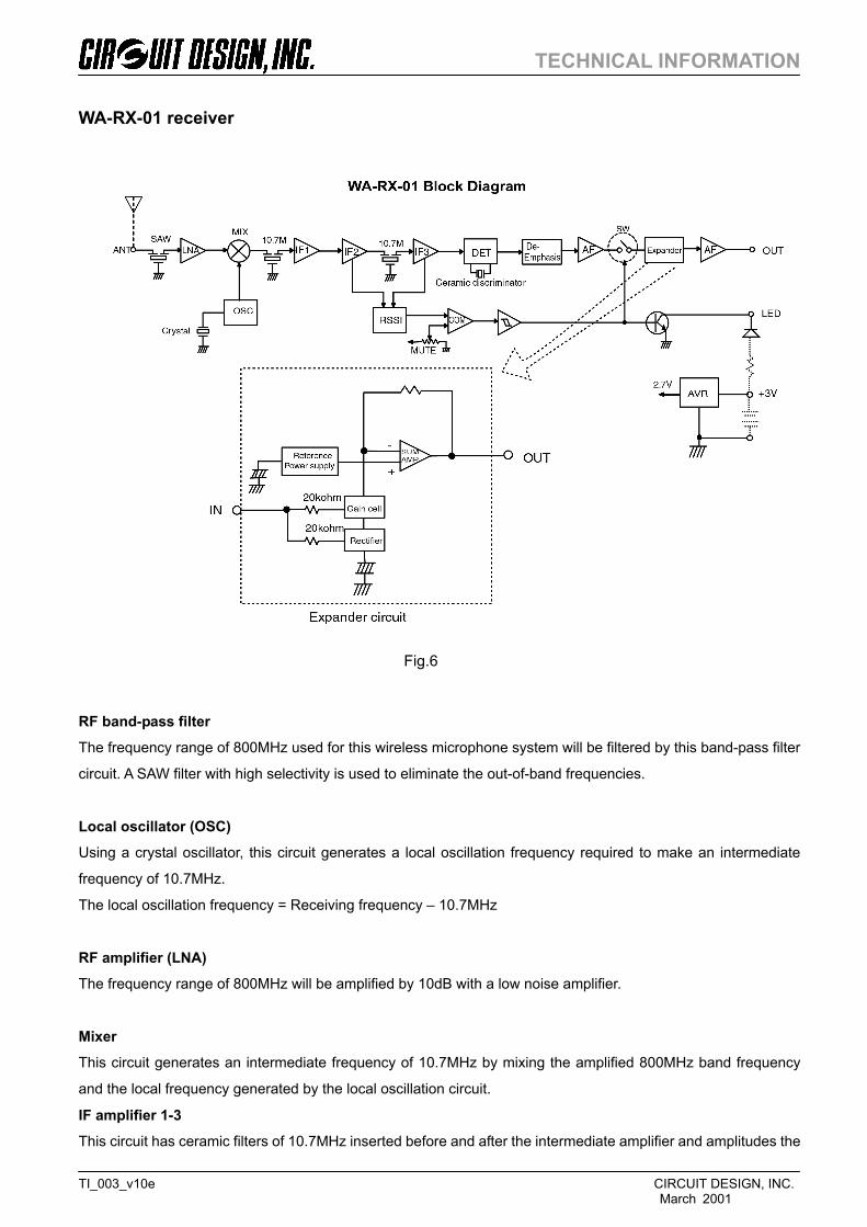
WA-RX-01 receiver
RF band-pass filter The frequency range of 800MHz used for this wireless microphone system will be filtered by this band-pass filter
circuit. A SAW filter with high selectivity is used to eliminate the out-of-band frequencies.
Local oscillator (OSC) Using a crystal oscillator, this circuit generates a local oscillation frequency required to make an intermediate
frequency of 10.7MHz.
The local oscillation frequency = Receiving frequency – 10.7MHz
RF amplifier (LNA) The frequency range of 800MHz will be amplified by 10dB with a low noise amplifier.
Mixer This circuit generates an intermediate frequency of 10.7MHz by mixing the amplified 800MHz band frequency
and the local frequency generated by the local oscillation circuit.
IF amplifier 1-3 This circuit has ceramic filters of 10.7MHz inserted before and after the intermediate amplifier and amplitudes the
Fig.6
TECHNICAL INFORMATION
TI_003_v10e CIRCUIT DESIGN, INC.
March 2001
intermediate frequency with an overall 100dB gain. And then at the last stage this circuit functions as a limiter
circuit.
FM detector This circuit demodulates the frequency modulated sound signal in the intermediate frequency (10.7Mhz) which
has been amplified and limited in the previous stage.
RSSI detector RF signals from the middle stage of the Intermediate amplifier are rectified to make direct current in accordance
with field strength.
Muting comparator Comparing the RSSI detect signals (field strength signals) to DC voltage set with a variable resistor, if the
antenna input signal goes down to 17dBuV or less, the audio output signal will be muted.
De-emphasis
The audio signal, whose higher frequency has been emphasized with a 50usec time constant in the transmitter,
will be de-emphasized with the same time constant to regain a flat frequency response.
AF amplifier This circuit amplifies the audio frequency which has been demodulated, to adjust it to the optimum matching
level for the expander circuit.
Analog switch If the field strength reduces too low, the audio signal will be blocked by this analog switch for muting.
Expander The audio signal from the analog switching circuit is expanded to double at a ratio of 1:2.
The input audio signal will be provided respectively to the gain cell and the full-wave rectification circuit. The
full-wave rectification circuit will detect the average value of the audio signal to generate a gain cell control
current.
Input-output relation of the expander is expressed;
Vout=(n x Rsum x Vin(av)/Io x Rrect x R∆G)Vin
Replacing the constant as A, the input-output will be;
Vout=A x Vin2=A x 2logVin
TECHNICAL INFORMATION
TI_003_v10e CIRCUIT DESIGN, INC.
March 2001
This shows the input-output relation has a ratio of 1:2.
As shown above, the audio signal from the analog switching circuit will be expanded at a ratio of 1:2. (see an
equivalent circuit) The matching level of the expander itself is –20dBv, which is the same as that of the
compander, and the signal more or less than –20dBv will be expanded logarithmically. For instance-10dBv will be
expanded to 0dBv, -30dBv will be expanded to –40dBv etc.
AF output amplifier The signal from the expander circuit will be amplified further and output externally.
LED driver This circuit drives the LED signals which show receiving status. When the field strength of the muting circuit
reaches a strong enough level to let the signal pass through the circuit, the open collector output terminal will
become Lo.
Voltage regulator This circuit is for supplying a stable voltage throughout the whole circuit.
The supply voltage is 2.8V to 10V. The output voltage is 2.7V.
As described in this article, this wireless audio module has a companding/expanding circuit as well as a
conventional RF circuit. Also the whole circuits including the power supply circuit has been produced very small.
We expect there is a great potential that this module is used for a variety of new applications that we have never
thought of before.
Please note that the detailed explanation for the diversity reception system was omitted since most parts are
repeated (see figure 7).

TEC
HN
ICA
L IN
FOR
MAT
ION
Circ
uit D
esig
n, In
c. A
ll rig
hts
rese
rved
. N
o pa
rt o
f thi
s do
cum
ent m
ay b
e co
pied
or d
istr
ibut
ed in
par
t or i
n w
hole
with
out t
he p
rior w
ritte
n co
nsen
t of C
ircui
t Des
ign,
In
c. M
arch
200
1
CIR
CU
IT D
ESIG
N, I
NC
. 7
557-
1 H
otak
a H
otak
amac
hi M
inam
iazu
mi N
agan
o 39
9-83
03 J
apan
Pho
ne: +
81 2
63 8
2 10
24
Fax:
+81
263
82
1016
e-m
ail:
cdin
t@ci
rcui
tdes
ign/
jp
Web
: http
://w
ww.
circ
uitd
esig
n.jp
Fig.
7