technical guide - rosetta hardscapes and typical, manufactured retaining wall and paver products....
TRANSCRIPT

STEPS • PAVERS • RETAINING WALLS • FIRE PITS • FIREPLACES
T E C H N I C A LG U I D E

T H E L O O K A N D F E E L O F N A T U R E
It’s been a few days on site as you lay the last block of the job and sweep off the top. You and your crew have worked hard, and your customer has become your friend. It’s hard to beat the feeling of a job well done, and you know that feeling better than anyone.
But too often, getting to the end of a project involves headaches and hiccups. What if you and your team could always quickly and easily install uniquely beautiful, quality hardscapes? Now you can.
With Rosetta Hardscapes, you can offer your customer an attractive alternative to both natural stone and typical, manufactured retaining wall and paver products. The hardscapes described in this technical guide are simply installed, but look just like natural stone. Your customer will love their finished landscape, and you’ll be able to get to that point of satisfaction even faster than normal.
With this guide you can wow the homeowners you work for without any added hassle. Whether your plan calls for retaining walls, pavers or steps, we’re here to help you create the most beautiful landscape possible. These pages explain the best way to get to your next stunning and satisfying, “ job well done.”
Rosetta Hardscapes2

TABLE OF CONTENTS
RETAINING WALL COLLECTIONOutcropping .......................................................... 4-5Belvedere ............................................................... 6-7Kodah .......................................................................... 8Dimensional Wall ..................................................... 9Claremont ................................................................. 10
PAVING/SLAB COLLECTIONGrand Flagstone ..................................................... 11Dimensional Flagstone ......................................... 1224x24 Flagstone ....................................................... 13Linear Flagstone ....................................................... 13Mission Paver Collection ...................................... 14Miros ............................................................................ 15Superior Steppers .................................................... 16
STEP COLLECTIONDimensional Steps ................................................. 16Irregular Steps ........................................................ 176’ Irregular Steps ...................................................... 17
ADDITIONAL COLLECTIONSCoping and Caps .................................................. 18Fireplace Kits ........................................................... 19Fire Pit Kits ............................................................... 20
RETAINING WALL INSTALLATION GUIDEGeneral Installation Instructions ....................21-24Outcropping .................................................... 25-28Belvedere ......................................................... 29-32Kodah ....................................................................... 33
PAVER INSTALLATION GUIDEGeneral Installation Instructions ....................... 34Grand Flagstone ............................................. 35-36Dimensional Flagstone ........................................ 37Mission Paver Collection ..................................... 38
STEP INSTALLATION GUIDEInstallation Instructions ........................................ 39
3

Stone & BundlingUnit
DimensionsL” x H”
Units/Bundle
Weight/Stone
lbs
42” x 12” 1 750 ±
48” x 12” 1 900 ±
60” x 12” 1 1100 ±
66” x 12” 1 1150 ±
24” x 6” 1 250 ±
36” x 6” 1 320 ±
60” x 18” 1 1600 ±
48” x 24” 1 1800 ±
24” x 6” 1 250 ±
36” x 6” 1 320 ±
48” x 6” 1 450 ±
36” x 12” 1 620 ±
54” x 12” 1 950 ±
72” x 12” 1 1300 ±
OUTCROPPING PALLET A• Pallet weight = ± 4000 lbs• Coverage = 18 sqft
OUTCROPPING PALLET C• Pallet weight = ± 4000 lbs• Coverage = 18 sqft
OUTCROPPING PALLET B • Pallet weight = ± 4000 lbs• Coverage = 18 sqft
Galvanized Steel hooks are available and required for reinforced walls.Actual weight and color may vary.
Rosetta Hardscapes4
OUTCROPPING COLLECTIONBLOCK DETAILS

Stone & BundlingUnit
DimensionsL” x W” x H”
Units/Bundle
Weight/Stone
lbs
Pallet D 60” x 30” x 12” 1 1540 ±
Pallet D 48” x 30” x 12” 1 1080 ±
Pallet D 48” x 30” x 6” 1 460 ±
Rosetta has two corner blocks to help make a 90º corner in the wall. The corner blocks are four-sided, and can be installed with alternating faces exposed to maintain a more random look.
The size of the corner blocks have been chosen to account for the wall batter in both directions. Two 6” high corner blocks are typically stacked on top of each other and placed on top of a 12” block. The corner blocks are intended to be stepped back 3” in both directions. In a few areas, you may need to trim a small part of the corner blocks near the back of the wall to avoid interference with the shear heels on adjacent blocks.
FREESTANDING PALLETS
For more information and cross sections, visit discoverrosetta.com > products > Outcropping > More On This Product
Stone & BundlingUnit
DimensionsL” x W” x H”
Units/Bundle
Weight/Stone
lbs
Corner 39” x 27” x 6” 4 480 ±
Corner 48” x 30” x 12” 3 1170 ±
Pallet E 72” x 30” x 12” 1 2080 ±
Pallet E 36” x 30” x 12” 1 880 ±
Pallet E 36” x 30” x 6” 1 440 ±
OUTCROPPING PALLET D • Pallet weight solid = ± 3150 lbs• Coverage = 11 sqft
OUTCROPPING PALLET E • Pallet weight solid = ± 3450 lbs• Coverage = 10.5 sqft
CORNERPALLET 12” • Pallet weight = ± 3600 lbs• Coverage = 19.5 sqft
CORNERPALLET 6” • Pallet weight = ± 2015 lbs• Coverage = 11 sqft
Technical Guide 5
OUTCROPPING COLLECTIONCORNER BLOCK DETAILS

Belvedere Collection wall blocks are provided in six basic sizes. The wall blocks are finished on both the front and back faces of the wall blocks and they are tapered on each side approximately 1” from the front to the back of the block. There are multiple face textures for each basic block size to provide a more random look for your finished project. Average block weights of the different face textures patterns are shown. Weights of individual blocks may vary.
CORNER PALLET• Pallet weight = ± 1,520 lbs (incl. pallet weight)• Coverage = 24 sqft / Pallet• Section = 1.5 sqft (one 6” piece and one 3” piece)
The Belvedere Collection contains 2 corner blocks. These blocks are finished on 3 sides, and the 4th side is tapered to fit with the other retaining wall blocks. The corner blocks can be used to construct columns, provide a finished end on a freestanding wall, and make 90° corners. There are multiple face textures for the faces of both column blocks sizes, thus providing a more random look for your finished project. Average block weights of the different face textures. Weight of individual blocks may vary.
WALL PALLET • Pallet weight = ± 2,475 lbs (incl. pallet weight)• Coverage = 27 sqft / Pallet when used in a Retaining Wall and
25 sqft / Pallet when used in a Freestanding wall• Section = 9 sqft per 2 layers (1 Layer of 6” and 1 Layer of 3”)
Corner PalletStone & Bundling
UnitDimensions
L” x W” x H”
UnitsBundle
Weight/Stone
lbs
Block 7 15” x 9” x 3” 16 30 ±
Block 8 15” x 9” x 6” 16 58 ±
Wall PalletStone & Bundling
UnitDimensions
L” x W”xH”
UnitsBundle
Weight/Stone
lbs
Block 1 6” x 9” x 3” 12 10 ±
Block 2 12” x 9” x 3” 12 20 ±
Block 3 18” x 9” x 3” 12 36 ±
Block 4 6” x 9” x 6” 12 21 ±
Block 5 12” x 9” x 6” 12 42 ±
Block 6 18” x 9” x 6” 12 67 ±
Rosetta Hardscapes6
BELVEDERE COLLECTIONBLOCK DETAILS
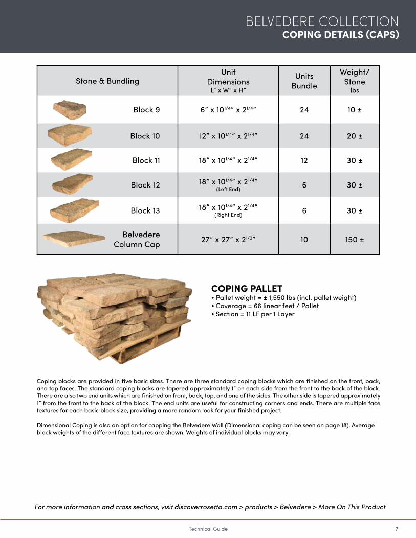
Coping blocks are provided in five basic sizes. There are three standard coping blocks which are finished on the front, back, and top faces. The standard coping blocks are tapered approximately 1” on each side from the front to the back of the block. There are also two end units which are finished on front, back, top, and one of the sides. The other side is tapered approximately 1” from the front to the back of the block. The end units are useful for constructing corners and ends. There are multiple face textures for each basic block size, providing a more random look for your finished project.
Dimensional Coping is also an option for capping the Belvedere Wall (Dimensional coping can be seen on page 18). Average block weights of the different face textures are shown. Weights of individual blocks may vary.
COPING PALLET • Pallet weight = ± 1,550 lbs (incl. pallet weight)• Coverage = 66 linear feet / Pallet• Section = 11 LF per 1 Layer
Stone & BundlingUnit
DimensionsL” x W” x H”
UnitsBundle
Weight/Stone
lbs
Block 9 6” x 101/4” x 21/4” 24 10 ±
Block 10 12” x 101/4” x 21/4” 24 20 ±
Block 11 18” x 101/4” x 21/4” 12 30 ±
Block 12 18” x 101/4” x 21/4”(Left End) 6 30 ±
Block 13 18” x 101/4” x 21/4”(Right End) 6 30 ±
BelvedereColumn Cap 27” x 27” x 21/2” 10 150 ±
For more information and cross sections, visit discoverrosetta.com > products > Belvedere > More On This Product
Technical Guide 7
BELVEDERE COLLECTIONCOPING DETAILS (CAPS)

KODAH FREESTANDING WALL PALLET • Pallet weight = ±2,500 lbs (incl. pallet weight)• Coverage = 21 sqft/pallet when used in a retaining wall and
20 sqft when used in a freestanding wall.• Section = 7 sqft per layer
The Kodah Collection contains two corner blocks. These blocks are finished on three sides, and the fourth side is tapered to fit with the other retaining wall and freestanding wall blocks. The corner blocks can be used to construct columns, provide a finished end on a freestanding wall, and make 90° corners. There are multiple face textures for the faces of both corner blocks, thus providing a more random look for your finished project. Average block weights of the different face textures are shown. Weights of individual blocks may vary.
Corner PalletStone & Bundling
UnitDimensions
L” x W” x H”
UnitsBundle
Weight/Stone
lbs
Block 1 21” x 10 1/2” x 6” 24 100 ±
Kodah Freestanding Wall Blocks are provided in four basic sizes. The blocks are finished on both the front and back faces of the wall blocks and they are tapered on each side approximately 1½“ from the front to the back of the block. There are multiple face textures for each basic block size to provide a more random look for your finished project. Average block weights of the different texture patterns are shown. Weights of individual blocks may vary.
Freestanding Wall PalletStone & Bundling
UnitDimensions
L” x W”xH”
UnitsBundle
Weight/Stone
lbs
Block 1 42” x 10 1/2” x 6” 6 200 ±
Block 2 30” x 10 1/2” x 6” 3 140 ±
Block 3 21” x 10 1/2” x 6” 6 100 ±
Block 4 12” x 10 1/2” x 6” 3 50 ±
KODAH CORNER PALLET • Pallet weight = ±2,500 lbs (incl. pallet weight)• Coverage = 31.5 sqft/pallet• Section = 1.3 sqft per piece
Rosetta Hardscapes8
KODAH COLLECTIONBLOCK DETAILS
Stone & BundlingUnit
DimensionsL” x W” x H”
UnitsBundle
Weight/Stone
lbs
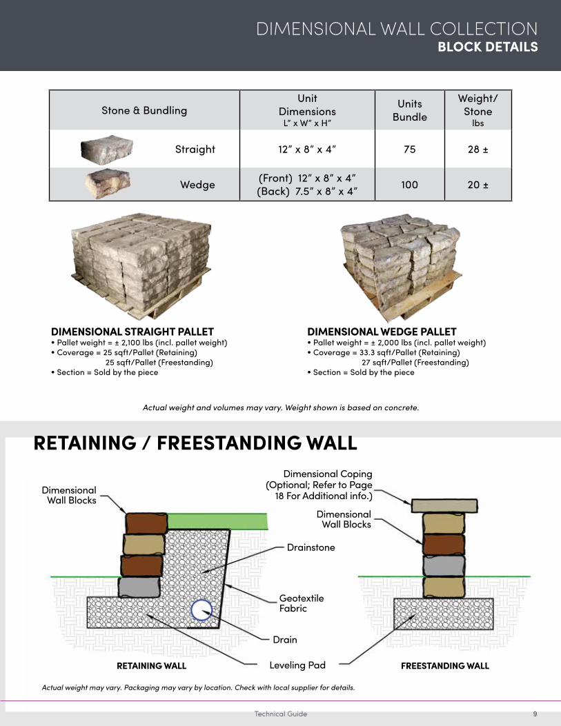
Straight 12” x 8” x 4” 75 28 ±
Wedge (Front) 12” x 8” x 4”(Back) 7.5” x 8” x 4” 100 20 ±
Actual weight and volumes may vary. Weight shown is based on concrete.
RETAINING WALL FREESTANDING WALL
Drain
Leveling Pad
GeotextileFabric
DimensionalWall Blocks
Dimensional Coping(Optional; Refer to Page
18 For Additional info.)
Drainstone
DimensionalWall Blocks
DIMENSIONAL STRAIGHT PALLET• Pallet weight = ± 2,100 lbs (incl. pallet weight)• Coverage = 25 sqft/Pallet (Retaining) 25 sqft/Pallet (Freestanding)• Section = Sold by the piece
DIMENSIONAL WEDGE PALLET• Pallet weight = ± 2,000 lbs (incl. pallet weight)• Coverage = 33.3 sqft/Pallet (Retaining) 27 sqft/Pallet (Freestanding)• Section = Sold by the piece
RETAINING / FREESTANDING WALL
Actual weight may vary. Packaging may vary by location. Check with local supplier for details.
Technical Guide 9
DIMENSIONAL WALL COLLECTIONBLOCK DETAILS

Stone & BundlingUnit
DimensionsL” x W” x H”
UnitsBundle
Weight/Stone
lbs
18” 18” x 8” x 4” 25 43 ±
24” 24” x 8” x 4” 25 61 ±
Corner 22” x 8” x 4” 40 53 ±
PILLAR CONSTRUCTION DETAILS
Place (4) Claremont corner blocks with the texture facingoutward.
Place the second row of (4) ofthe corner blocks with the texture facing outward.
Continue with subsequent rows to the desired pillar height. One pallet of corner blocks will make a 30” x 30” x 40” high column.
Place a column cap to finishthe pillar. The column capcan be cored as needed forinstallation of a lamp.
Step 1
Step 4Step 3
Step 2
This page shows typical construction details for Claremont pillars. Pillars make nice ends to Freestanding walls, formal stair openings, stand-alone monuments, and other areas to enhance your Claremont project. The basic steps of pillar construction are shown here. Feel free to expand on these ideas and bring your own imagination into creating a custom project.
Min. Radius = 14’
OUTSIDE CURVEThe minimum radius without cutting is 14’. Wall aesthetics can be improved by using a radius larger than the minimum required.
CLAREMONT WALL PALLET• Pallet weight = ± 2,800 lbs (incl. pallet weight)• Pieces on Pallet = 25 pieces of 18”, 25 pieces of 24”• Coverage = 29 sqft/Pallet• Section = 1.16 sqft = 1ea 18” and 1ea 24”
CLAREMONT CORNER PALLET• Pallet weight = ± 2,200 lbs (incl. pallet weight)• Pieces on Pallet = 40 pieces• Coverage = 33.3 sqft/Pallet• Section = .83 sqft = 1 piece (section sold by the piece)
For more information and cross sections, visit discoverrosetta.com > products > Claremont > More On This Product
Rosetta Hardscapes10
CLAREMONT COLLECTIONBLOCK DETAILS

CLAREMONT CORNER PALLET• Pallet weight = ± 2,200 lbs (incl. pallet weight)• Pieces on Pallet = 40 pieces• Coverage = 33.3 sqft/Pallet• Section = .83 sqft = 1 piece (section sold by the piece)
Layers 1 and 5Outside dimensions of each layer are identical to all other layers, allowing any layer to be used anywhere in the pattern. Random assortment of layers provided on each pallet. Exact proportion of layers and layer designs may vary.
Grand Flagstone - 1.75” Thick
Compacted Gravel Base
Coarse Bedding Sand
Joint Sand
Compacted Sub-base Material
GRAND FLAGSTONE PALLET• 8 Layers per pallet• Pallet weight = ± 2,000 lbs (incl. pallet weight)• Coverage = 90 sqft/Pallet• Section = 11.25 sqft per 1 layer
38”
42”
Random assortment of layers provided on each pallet.Exact proportion of layers and layer designs may vary.
*Each layer contains three or four indvidual pieces
*Not suitable for vehicular applications
PACKAGING
COMMON POINTS FOR INTERLOCKING LAYERS
PROPERLY PLACED INTERLOCKING LAYERS
Layers 2 and 6 Layers 3 and 7 Layers 4 and 8
38” (0.96 m)
42”(1.07 m)
Layers 1 and 5 Layers 2 and 6
Layers 3 and 7 Layers 4 and 8
Technical Guide 11
GRAND FLAGSTONE COLLECTIONBLOCK DETAILS

Dimensional Flagstone
Coarse Bedding Sand
Joint Sand
Compacted Gravel Base
Compacted Sub-base Material
42”
42”
DIMENSIONAL FLAGSTONE PALLET• All sizes on every pallet• Consistent 2” thickness• One layer = one pattern• 8 layers per pallet• Pallet weight = ± 2,350 lbs (incl. pallet weight)• Coverage = 98 sqft/Pallet• Section = 12.25 sqft per layer
PATIO LAYOUTWALKWAY LAYOUTDIMENSIONAL FLAGSTONE CROSS-SECTION
Coarse Bedding Sand(1” (25 mm) Thick)
Dimensional Flagstone Slabs(2” (45mm) Thick)
Jointing Sandbetween Slabs
Compacted Gravel Base(6” (150 mm) Thick)
Woven geotextile(Optional)
Compacted Existing Sub-Grade
42”
18 x 24
24 x 2418 x 18
12 x 18
12 x 12 12 x 6
18”x 24”
24”x 24”
18”x 18”
12”x
12”
12”x 6”
12”x
18”
*Not suitable for vehicular applications
Rosetta Hardscapes12
DIMENSIONAL FLAGSTONE COLLECTIONBLOCK DETAILS

24x24 FLAGSTONE
LINEAR FLAGSTONE
• Same size 24”x24” pieces• Consistent 2” thickness• Pallet weight ± 1600 lbs (incl. pallet weight)• Coverage = 64 sqft/pallet• Units per bundle = 16• Weight per stone = 96 lbs
• Same size 21”x 10.5” pieces• Consistent 2” thickness• Pallet weight ± 2350 lbs (incl. pallet weight)• Coverage = 98 sqft/pallet• Units per bundle = 64• Weight per stone = 37 lbs
** 24x24 Flagstone slabs must be spaced apart a minimum of 1/8”. These slabs were originally developed for use with roof-top pedestal mount systems. On-grade installations require manually spacing the slabs apart. This can be achieved using a pair of 1/8” wooden shims or by using removable tile spacers. Failure to provide a relief joint will restrict the seasonal flexibility of the patio.
Technical Guide 13
*Not suitable for vehicular applications
*Not suitable for vehicular applications
24X24 FLAGSTONEBLOCK DETAILS

Stone & Bundling UnitDimensions
L” x W” x H”
UnitsBundle
Weight/Stone
lbsOld Mission New Mission
6 x 9 511/16” x 81/2” x 23/4” 80 10 ±
9 x 9 81/2” x 81/2” x 23/4” 40 15 ±
12 x 9 115/16” x 81/2” x 23/4” 80 20 ±
PAVER PALLET • Pallet weight = ± 3050 lbs (incl. pallet weight)• Coverage = 100 sqft/Pallet• Section = 12.5 sqft per 1 layer• 8 Layers per pallet
• Available in three sizes and multiple face textures, each included on a single pallet• Old Mission is suitable for both standard and permeable paver installation• Suitable for residential vehicular traffic
*When snowplowing Mission Pavers, a poly cutting edge must be used to avoid marking the surface of the paver.
Old Mission Pallet New Mission Pallet
Wider joint for permeable applications
OLD MISSION NE W M I S S ION
Tighter joint for non- permeable applications
Old Mission Pavers
Joint Sand
Coarse Bedding Sand
Compacted Gravel Base Woven Geotextile Fabric
Compact Sub-base Material
Typical Paver Cross-Section
Optional Soldier Course Using the Mission Paver CollectionA soldier course can be created around the edge of the paving
by aligning Mission Pavers in the 9” nominal directions
Rosetta Hardscapes14
MISSION PAVER COLLECTIONBLOCK DETAILS
MIROS PAVER CROSS-SECTION
Stone & BundlingUnit
DimensionsL” x W” x H”
UnitsBundle
Weight/Stone
lbs
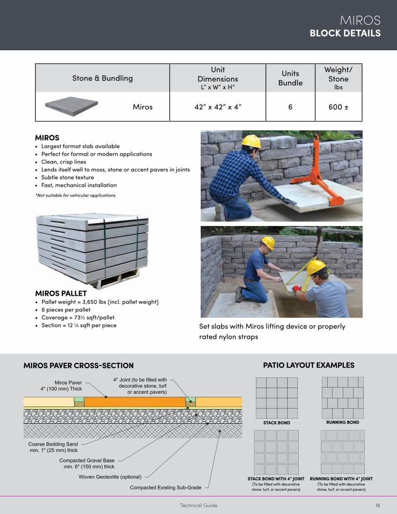
Miros 42” x 42” x 4” 6 600 ±
MIROS• Largest format slab available• Perfect for formal or modern applications• Clean, crisp lines• Lends itself well to moss, stone or accent pavers in joints• Subtle stone texture• Fast, mechanical installation*Not suitable for vehicular applications
MIROS PALLET• Pallet weight = 3,650 lbs (incl. pallet weight)• 6 pieces per pallet• Coverage = 73½ sqft/pallet• Section = 12 ¼ sqft per piece
PATIO LAYOUT EXAMPLES
STACK BOND RUNNING BOND
STACK BOND WITH 4” JOINT(To be filled with decorative stone, turf, or accent pavers)
Set slabs with Miros lifting device or properly rated nylon straps
RUNNING BOND WITH 4” JOINT(To be filled with decorative stone, turf, or accent pavers)
Technical Guide 15
MIROSBLOCK DETAILS

DIMENSIONAL PALLET
Stone & BundlingUnit
DimensionsL” x W” x H”
UnitBundle
Weight/Stone
lbs
Weight/Pallet
lbs
3’ 36” x 18” x 7” 8 375 ± 3050 ±
4’ 48” x 18” x 7” 8 500 ± 4050 ±
4’ XL 48” x 24” x 7” 4 675 ± 2750 ±
6’ 72” x 30” x 7” 3 1333 ± 4000 ±
DIMENSIONAL STEPS
SUPERIOR STEPPERS PALLET• 16 pc/pallet (Random Assortment)• Pallet weight = 1,300 lbs (incl. pallet weight)• Coverage = 52 sqft/pallet• Section = 3.25 sqft per 1 piece
SteppersUnit
DimensionsL” x W” x H”
Weight/Stone
lbs
Stepper 1 27” x 21” x 2” 78 lbs
Stepper 2 27” x 21” x 2” 78 lbs
Stepper 3 27” x 21” x 2” 78 lbs
Stepper 4 27” x 21” x 2” 78 lbs
Superior Stepping Stone2” (50 mm) thick
Coarse Bedding Sand Min. 1” (25 mm) Thick Compacted
Turf Between Superior Stepping Stones
Compacted Existing Sub-base Material
Typical Cross-Section
DRAWN BY:
DRAWING FILE:SHEET NO. :
DATE:
05481 US 31 SOUTH CHARLEVOIX, MI 49720877-777-6558 ● 231-237-9656 Fax ● www.discoverrosetta.com
TITLE:
APPROVED BY: SUPERIOR STEPPING STONE CROSS-SECTIONB CONKLIN
FEB 3, 2016
1 OF 1 SUPERIOR STEPPER SECTION.dwg
TYPICAL SECTION
SteppersUnit
DimensionsL” x W” x H”
Weight/Stone
lbs
Stepper 5 27” x 21” x 2” 78 lbs
Stepper 6 27” x 21” x 2” 78 lbs
Stepper 7 27” x 21” x 2” 78 lbs
Stepper 8 27” x 21” x 2” 78 lbs
Rosetta Hardscapes16
SUPERIOR STEPPERS & STEP COLLECTIONBLOCK DETAILS
Stone & BundlingUnit
DimensionsL” x W” x H”
UnitBundle
Weight/Stone
lbs
Weight/Pallet
lbs
3’ 36” x 18” x 7” 8 375 ± 3050 ±
4’ 48” x 18” x 7” 8 500 ± 4050 ±
4’ XL 48” x 24” x 7” 4 675 ± 2750 ±
6’ 72” x 30” x 7” 3 1333 ± 4000 ±
Technical Guide 17
STEP COLLECTIONBLOCK DETAILS
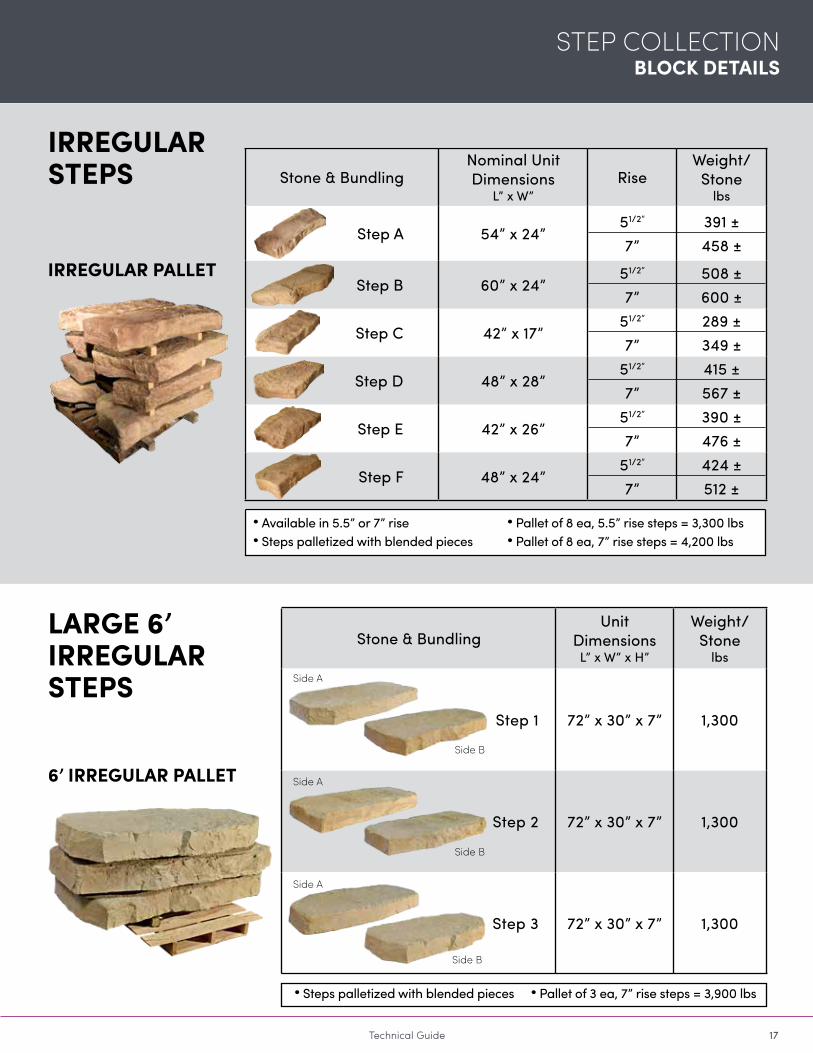
Stone & BundlingNominal UnitDimensions
L” x W”Rise
Weight/Stone
lbs
Step A 54” x 24”51/2”
7”391 ±458 ±
Step B 60” x 24”51/2”
7”508 ±600 ±
Step C 42” x 17”51/2”
7”289 ±349 ±
Step D 48” x 28”51/2”
7”415 ±567 ±
Step E 42” x 26”51/2”
7”390 ±476 ±
Step F 48” x 24”51/2”
7”424 ±512 ±
. Available in 5.5” or 7” rise. Steps palletized with blended pieces
. Pallet of 8 ea, 5.5” rise steps = 3,300 lbs. Pallet of 8 ea, 7” rise steps = 4,200 lbs
IRREGULAR PALLET
IRREGULAR STEPS
. Steps palletized with blended pieces . Pallet of 3 ea, 7” rise steps = 3,900 lbs
6’ IRREGULAR PALLET
Stone & BundlingUnit
DimensionsL” x W” x H”
Weight/Stone
lbs
Step 1 72” x 30” x 7” 1,300
Step 2 72” x 30” x 7” 1,300
Step 3 72” x 30” x 7” 1,300
LARGE 6’ IRREGULAR STEPS Side A
Side A
Side A
Side B
Side B
Side B

Stone & BundlingUnit
DimensionsL” x W” x H”
UnitsBundle
Weight/Stone
lbs
24”Dimensional
Coping24” x 12.5” x 2.5” 18 63 ±
18”Dimensional
Coping18” x 12.5” x 2.5” 12 47 ±
Dimensional Coping
End19” x 12.5” x 2.5” 6 49 ±
Dimensional Coping Pallet• Pallet weight = 2,000 lbs• 6 Layers per pallet• 63 LF/pallet• Section = 10.5 LF per 1 layer
Bullnose Corner Pallet• Pallet weight = 950 lbs• 3 Layers per pallet• 9 rights and 9 lefts • Section = Sold by the piece
Stone & BundlingUnit
DimensionsL” x W” x H”
UnitsBundle
Weight/Stone
lbs
27”Column Cap 27” x 27” x 2.5” 10 150 ±
24” Column Cap 24” x 24” x 2.5” 10 120 ±
30”Column Cap 30” x 30” x 3” 6 230 ±
34”Pillar Cap 34” x 34” x 3” 6 295 ±
Stone & BundlingUnit
DimensionsL” x W” x H”
UnitsBundle
Weight/Stone
lbs
BullnoseStandard 22” x 14” x 2” 18 50 ±
BullnoseRight Corner 22” x 14” x 2” 9 50 ±
BullnoseLeft Corner 22” x 14” x 2” 9 50 ±
Bullnose Standard Pallet• Pallet weight = 950 lbs• 3 Layers per pallet• 33 LF/pallet • Section = Sold by the piece
*Belvedere coping, see page 7
Rosetta Hardscapes18
CAPS & COPINGBLOCK DETAILS

Technical Guide 19
FIREPLACE KITS
COMPONENTS
ROSETTA FIREPLACEKIT COMPONENTS
FOUNDATION INSTALLATION DETAIL
CLAREMONT FIREPLACE
BELVEDERE FIREPLACE
MASONRY COMPONENTS
Bag ofMortar
• Miscellaneous Fasteners• Detailed Instructions
Mortar
4'-6" Wide x 7'-0" Long
12"
Precast Fireplace Hearth
Crushed Stone Footing
WovenGeotextile
Bury Untextured Portionof Hearth Below Grade
PrecastFireplaceFirebox
6"6"
Visit discoverrosetta.com > products > Fireplace Kits > More On this Product
Each piece is a solid precast unit featuring the texture of stacked limestone.
9’ 8”
6’ 0”
3’ 8”
6’ 0”
9’ 8”
3’ 8”

ROUND FIRE PIT ± 2” Gap
37” DIA. Steel Ring
Blocks
Cap Layer(3 CapBlocksShown For Reference)
Round Fire Pit Pallet: 1,320 lbs
SQUARE FIRE PIT
Square Fire Pit Pallet: 1,130 lbs
Caps
37” DIA.Steel Ring
±2” Gap
Drain stone
Caps Don’tContact Lip of
Steel Ring
28” x 28 x 12” Tall Steel Liner(Hangs Directly on Blocks)
Overlap Blocks atCorners as shown
DimensionalWall Blocks
INSTRUCTIONS: For both Round & Square Fire Pit Kits
1. Familiarize yourself with the construction details shown on this page.2. Mark out the location for your fire pit. Note dimensions shown are nominal so mark an area slightly larger than shown.3. Excavate for drain stone base (approx. 6”)4. Fill excavation with drain stone, level, and compact.5. Place and center steel ring on prepared base.6. Place blocks per the pattern. (For Round Kit, keep Blocks 1 1/2” off steel ring)7. WARNING: Do not place Rosetta Fire Pits directly on Rosetta Flagstone product or any comparable concrete product or slab as high heat can adversely affect the integrity of the product. ADDITIONAL INSTRUCTIONS FOR ROUND FIRE PIT ONLY8. After placing blocks around the ring, adjust the blocks in or out to make the circle close and fit tight. If the blocks do not close the circle, move all blocks slightly in. If the blocks seem too long, move the blocks slightly out.9. Place caps in circle around fire pit. Adjust the caps in or out to make them fit tightly together.10. Note: Not suitable for large fires. Fire size should not allow flame to contact Caps on Round Fire Pit.
Gas conversion kits are available for both Round and Square Fire Pit Kits.
Rosetta Hardscapes20

ROSETTA RETAINING WALL INSTALLATION NOTES
Thank you for your interest in installing a quality retaining wall system by Rosetta Hardscapes. The following guide describes proper installation techniques for the Rosetta Outcropping, Kodah, Belvedere, Dimensional, and Claremont Wall systems. This installation guide will help cover the basic steps required to construct a beautiful, structurally sound retaining wall. For optimal color blending you must mix and install products from several different pallets simultaneously.
PRE-CONSTRUCTION CHECKLIST
Before you start construction, take the time to complete the necessary planning and preparation. This process will keep your project running efficiently and will aid in completing a quality installation. Make sure to address the following:
SAFETYYour safety program should address items such as personal protective equipment, maintaining safe slopes and excavations, fall protection, rigging and lifting, as well as any other relevant safety precautions.
ENGINEERING AND PERMITSObtain the necessary engineering design and permits for your project. The soils for foundation and wall backfill should be properly evaluated by a trained professional. Unsuitable soils should be removed and replaced as recommended.
Note: This installation guide is intended to supplement a detailed, site-specific wall design prepared by a Professional Engineer. The construction documents for your project supersedes any recommendations presented here.
REVIEW THE PROJECT PLANSTake the time to review and understand the project plans and specifications. Make sure you understand the detailed design for the project before starting construction. A pre-construction meeting with the wall designer, construction inspector, wall contractor, and owner or representative is recommended. Don’t be afraid to ask questions.
CONSTRUCTION PLANNINGDevelop a plan to coordinate construction activities (material delivery/storage, equipment access, etc.) on your site. Make sure your plan specifically addresses how to control surface water during construction.
UTILITY LOCATIONMake sure to have underground utilities located and marked on the ground before starting any construction.
Call 8-1-1 or go online to call811.com to schedule utility marking for your project site.
MATERIAL STAGINGStore retaining wall blocks in a location close to the proposed wall. Blocks should be kept clean and mud free. Blocks should also be stored in a location which will minimize the amount of handling on the project site.
Store geogrid in a clean, dry location close to the proposed wall site. Keep the geogrid covered or in the shade until installation to avoid exposure to direct sunlight.
EQUIPMENTMake sure you have the proper equipment to handle retaining wall blocks and pallets on the construction site (Note: A specially designed Rosetta Lifting Device is required for the installation of Rosetta Outcropping blocks).
Hand operated equipment used in wall construction should include shovels, rake, 2’ (600 mm) level, 4’ (1.2 m) level, broom, hammer, chisel, tape measure, string, spray paint, laser level, pry bar, concrete saw and a walk behind vibratory plate compactor capable of delivering a minimum of 2000 lb (9 kN) centrifugal force.
Personal protective equipment should include appropriate clothing, steel toe boots, eye protection, respiratory protection, hard hat, gloves, hearing protection, fall protection, rigging, and other items as necessary to insure a safe working environment.
For the most natural appearance, install products from multiple pallets simultaneously. This will create a more blended, natural look.
Technical Guide 21
INSTALLATION INSTRUCTIONSRETAINING WALL (GENERAL)

BASE PREPARATIONProper base preparation is a critical element in the construction of your retaining wall. Not only is it important to provide a stable foundation for the wall, but a properly prepared base will greatly increase the speed and efficiency of your wall installation.
Proper base preparation starts with the sub-grade soils (soils below the leveling pad). Existing soils must be removed to the bottom of the leveling pad elevation for the retaining wall. A typical wall requires excavation of at least 12” (300 mm). This will provide 6” (150 mm) for the leveling pad and 6” (150 mm) of minimum bury of the blocks. (Note: excavation and bury depth will vary by product type and design. Please see project plans or product specific information for further information.) At a minimum, all topsoil, organic, unsuitable soils should be removed from below wall. The minimum width of the leveling pad should be 18” (465 mm) wider than the width of the block. This will provide 6” (150 mm) in front of and 12” (300 mm) behind the bottom block.
Once excavated, the sub-grade soil should be compacted to a minimum of 95% maximum density as determined by a standard proctor test (ASTM D698). At this point the soil should be firm, dry and free of topsoil debris, stones, roots, etc. Consult a soils engineer if in doubt. Any unsuitable material shall be excavated and replaced as directed by the engineer.
LEVELING PADBase preparation continues with proper leveling pad construction. An open graded (free-draining) crushed stone leveling pad is typically used for retaining walls. Walls can also be designed with a dense-graded crushed stone or concrete leveling pad. The choice of which type of leveling pad to use is made by the wall designer and depends on several factors including the bearing capacity of the native soil, location of the drain outlet, conditions at the base of the wall, and any other special considerations for the wall.
The leveling pad material should be placed and compacted to provide a uniform, level foundation on which to construct the retaining wall. Proper elevation can be established with a laser level or transit. Check for level both parallel and perpendicular to the wall.
Place and compact leveling pad material as specified in the wall design. If crushed stone is used, place the stone in uniform loose lifts a maximum of 6” (150 mm) thick. Lift sizes are relative to size of the compactor being used. Compact the stone with a minimum of three passes with a 24” (600 mm) wide, walk-behind, vibrating plate compactor.
NOTE: Do NOT place a thin layer of sand between the leveling pad and bottom block. This layer will reduce the sliding resistance between the leveling pad and bottom block, as well as reduce the drainage capacity of the foundation stone.
DRAINA drain is installed in the lowest part of the open graded (free-draining) stone behind the retaining wall. If an open graded crushed stone leveling pad is used, the drain is installed on the bottom of the crushed stone leveling pad. If a dense graded crushed stone leveling pad is used, the drain is installed immediately on top of the dense graded stone.
Typically, a 4” (100 mm) diameter perforated “sock” pipe is used. Daylight the drain pipe at the ends and/or through the face of the wall every 50’ to allow for drainage. The pipe can also outlet into a nearby drainage ditch or catch basin. Because water can flow both ways through the drain pipe, connection to a catch basin or active storm sewer should only be made under the direction of a Professional Engineer.
Rosetta Hardscapes22
INSTALLATION INSTRUCTIONSRETAINING WALL (GENERAL)

SETTING THE BOTTOM COURSE OF BLOCKS
Proper placement of the bottom course of wall stones is critical in determining the overall appearance and integrity of the finished project. Take extra time on this step and the rest of the project will go smoothly. At this point you need to determine the best point of origin for the wall. If you have a fixed point, such as a building corner or a 90° corner, you will want to start the wall from that point and work your way out. This will minimize cutting of blocks. If there are no fixed points, start the wall at the lowest design elevation, as it is easier to step the base up than it is to step the base down.
Properly mark the location of the retaining wall. A string line or offset stakes are typically used to establish horizontal and vertical alignment.
Where applicable, remove the bottom lip from the back edge of the blocks with a hammer and chisel (bottom course of blocks only) so the blocks will lie flat on the leveling pad.
Place a complete row of blocks on the prepared leveling pad. Blocks should be placed tight together.
Check all blocks for level from front to back and side to side as they are placed. Place and compact backfill in front of the bottom row of blocks to help hold them in place. Compaction should be to 95% maximum density as determined by a standard proctor test (ASTM D698).
Place open-graded crushed stone, between the blocks, and at least 12” (300 mm) behind the wall. A stone meeting the gradation requirements of ASTM No. 57 with no material passing the No. 200 sieve is preferred. Place the stone in uniform loose lifts a maximum of 8” (200 mm) thick. Fully consolidate the stone. Carefully hand tamp the stone within 12” (300 mm) of the blocks.
Place non-woven geotextile fabric between the drainstone and the remaining backfill material if specified.
Backfill behind the drainstone with material as specified in the project design. Place the material in loose lifts as specified, but not to exceed 8” (200 mm) maximum. Granular backfill shall be compacted to a minimum of 95% maximum density as determined by a standard proctor test (ASTM D698). Do not use any organic, topsoil, frozen, soft, wet, or loose soils when backfilling the wall.
Re-check all units for level and alignment and sweep the top of each course of blocks clean before starting construction of the next course.
SETTING THE UPPER COURSES OF BLOCKSPlacing the next course of blocks is similar to placing the first course. Blocks should be placed to establish a running bond pattern (Rosetta Dimensional Collections) or to follow an irregular pattern (Rosetta Outcropping, Belvedere, and Claremont Collections).
Blocks should be installed with their sides pushed tight. Push blocks from Rosetta Outcropping collections forward until the lip on the back of the block comes in full contact with the blocks below. Make sure that no stones get caught or wedged between the lip and the back of the blocks below. Walls without the lip on the bottom (Rosetta Belvedere, Dimensional, Kodah Freestanding, and Claremont Collections) should not be stacked exactly vertical. Instead, they should be set back as specified by each product line.
Rosetta Outcropping: Place a layer of non-woven geotextile fabric directly behind the blocks. This will keep materials from eroding through the small voids between the blocks.
Place Geogrid reinforcing behind the wall as specified in the project documents. See geogrid Installation information in the next section for further details.
Place and compact open-graded crushed stone in the cores of the blocks, between the blocks, and at least 12” (300 mm) behind the wall following the procedure used for the bottom course of blocks.
Place non-woven geotextile fabric between the drainstone and the remaining backfill material if specified.
Place and compact backfill behind the drainstone following the procedure used for the bottom course of blocks.
Re-check all units for level and alignment and sweep the top of each course of blocks clean before starting construction of the next course.
Repeat these steps with each course of blocks to the top of the wall.
Technical Guide 23
INSTALLATION INSTRUCTIONSRETAINING WALL (GENERAL)

GEOGRID INSTALLATION
Stability of reinforced soil walls rely on the interaction between geogrid reinforcement, soil in the reinforced zone, and the retaining wall blocks. It is very important that reinforced soil walls be constructed per the detailed design prepared by a Professional Engineer. Make sure you are using the proper type and strength of geogrid listed in the design. The geogrid layers need to be placed at the proper elevations and to the proper distances into the reinforced soil zone detailed in the design. It is also critical to use the appropriate backfill soil material in the reinforced soil zone.
Construct the wall up to the elevation of the geogrid layer shown in the design.
Place geogrid layers as shown in the project details extending into the reinforced soil zone to the design length.
Geogrid must be installed with the strong direction (roll direction) into the reinforced soil zone and not parallel to the wall. Geogrid must be placed in a continuous sheet throughout its length from the connection at the blocks to the back of the reinforced zone. Do not splice or overlap the geogrid.
For all retaining wall products except the Rosetta Outcropping Collection, use the next layer of blocks to secure the front end of the geogrid. Make sure the geogrid is as close as possible to the front face of the wall without being visible. Pull the geogrid taut to eliminate any folds and pretension the geogrid. Pin or secure the back edge of the geogrid before placing the reinforced fill.
MORE INFO
Refer to product specific Typical Construction Details for specific applications and construction practices such as chimney drain construction, fence installation, corner construction, drain placement, curve construction, and other details.
Typical allowable construction tolerance at the wall face is 1” in 10’ (1:120) in the vertical and horizontal directions, and a rotation tolerance of 2° from wall batter.
Once you commence working, continue without interruption or delays. This will help expedite construction and minimize the time the excavation is open.
If at any time ground water seepage is observed along the exposed excavation behind the retaining wall, contact the wall designer immediately to determine the corrective action needed.
The construction site should be graded and maintained to direct surface water runoff away from the retaining wall throughout the entire construction process. If there is a rain event with surface water runoff producing erosion or scour near the retaining wall, contact the wall designer immediately to determine the corrective action needed.
FINISHING THE TOP OF THE WALL
Completing a few simple tasks near the end of the project will ensure that the wall will function properly and look good for years to come.
Grade the top of the wall in such a way that surface water runs off away from the wall. Never leave the top of a wall graded where surface water will pond behind the wall, or saturate the backfill soils.
Place a layer of non-woven geotextile fabric over the top of the drainstone at the back of the wall. This will keep topsoil from migrating into the drainstone and causing problems.
If required, place the coping layer on the top of the wall. The coping blocks should be placed towards the front edge of the wall blocks and should sit securely on top without tipping forward under their own weight. The coping layer should be carefully adhered with a concrete adhesive specifically formulated for segmental concrete block wall construction.
Rosetta Hardscapes24
INSTALLATION INSTRUCTIONSRETAINING WALL (GENERAL)

RETAINING WALL
TYPICAL FREESTANDING WALLThis page shows typical construction details for Outcropping Freestanding walls. These drawings are representative of major components required in wall construction. Specific details including drainage details, soil requirements, etc shall be per engineered design for wall.
Block size and placement shown are for reference only. Individual Rosetta blocks will vary with installation pattern.
NOTE: Block size and placement shown are for reference only. Individual Rosetta blocks will vary with installation pattern. Actual design must be performed by licensed engineer.
TYPICAL GRAVITYWALL SECTIONThis page shows typical construction details for Gravity walls. These drawings are representative of major components required in wall construction. Specific details including geotextile reinforcement layers, drainage details, soil requirements, etc shall be per engineered design for wall. For more cross-section and design options, please visit discoverrosetta.com and click on Tech Resources
3 x 0.53 x 0.5
4 x 0.54 x 0.5
4 x 1
4 x 1
6 x 1
6 x 1
3 x 1
5 x 1 5 x 1
3 x 0.54 x 0.5
4 x 16 x 1
6 x 13 x 1
5 x 1
3 x 0.54 x 0.5
4 x 1
6 x 1
5 x 1
3 x 1
4 x 1 3 x 0.54 x 0.5
4 x 1
6 x 14 x 0.5
3 x 0.5
5 x 1
5 x 1
11- 12 FT 12-12 F
T
3 x 0.53 x 0.5
4 x 0.54 x 0.5
4 x 1
4 x 1
6 x 1
6 x 1
3 x 1
5 x 1 5 x 1
3 x 0.54 x 0.5
4 x 16 x 1
6 x 13 x 1
5 x 1
3 x 0.54 x 0.5
4 x 1
6 x 1
5 x 1
3 x 1
4 x 1 3 x 0.54 x 0.5
4 x 1
6 x 14 x 0.5
3 x 0.5
5 x 1
5 x 1
11- 12 FT 12-12 F
T
FREESTANDING WALL PATTERNS
4’ x 10’ Freestanding Wall Section(2x Pallet D, 2x Pallet E)
90° Freestanding Wall Corner(4x Pallet D, 4x Pallet E)
Technical Guide 25
INSTALLATION INSTRUCTIONSOUTCROPPING

Outcropping Notes For Installations Requiring Geogrid:
Please visit discoverrosetta.com for detailed cross-sections of geogrid reinforced Outcropping walls. For Rosetta Outcropping installations, do not overlap geogrid over top of blocks. Instead, run the geogrid directly up to the back of the blocks. In addition to this reinforcement, a Paraweb strap must be installed through each lifting hook in the back of the Outcropping blocks. Please see standard details for Reinforced Outcropping Walls for further information.
Place and compact drainstone and reinforced fill following the procedure used to set the bottom and upper courses of blocks. It is important to place and compact stone and reinforced fill starting at the back of the retaining blocks and extending into the reinforced soil zone. This will help eliminate “bunching” of the geogrid reinforcement.
Reinforced zone fill material is typically a sand or gravel with less than 5% “fines” (material passing the No. 200 sieve). This material is usually classified as a GW, GP, SW, or SP. It is very important that you only use the fill material specified in your project design drawings and specifications.
Place retained soil immediately between the reinforced soil zone and the back of the excavation. Material should be placed in loose lifts of 8” (200 mm) maximum and compacted to 95% maximum density as determined by a standard proctor test (ASTM D698). Bring the reinforced and retained soil up to grade at the same time. At no time should the elevation of the reinforced soil be more than 1 block higher than the retained soil.
Tracked construction equipment should not be used directly on the geogrid. A minimum of 6” (150 mm) of fill is required between tracked equipment and geog-rid to prevent damage to the grid. Rubber- tired equipment may pass over the geogrid when traveling at low speeds of 5 mph (8 km/h) or less.Avoid any sudden stopping or turning of construction equipment in the reinforced fill zone to prevent moving or damaging the geogrid layers.
Follow geogrid manufacturer’s requirements, including requirements for vertical separation and overlap of geogrid.
Outcropping Layout Notes:
One of the unique features of the Rosetta Outcropping system is multiple block heights. To provide a uniform wall batter with multiple height blocks, the set-back of the blocks varies proportionally with the block height. The setback in blocks is achieved with shear heels which are cast into the Rosetta blocks. For a 6” high block, the shear heels are 1.5” deep (1/2 times 3”). For a 12” high block, the shear heels are 3” deep (1 times 3”). For a 24” high block, the shear heels are 6” deep (2 times 3”).
To ensure proper wall alignment and to account for the multiple height blocks and varying setbacks, you have to adjust the bottom row of blocks based on their height. Setup a traditional string line for the back of the wall, then offset the blocks per the following figure.
Outcropping Lifting DeviceOutcropping lifting device required forproper installation
For All InstallationsNever stack blocks more than one course above grade of backfill.
Rosetta Hardscapes26
INSTALLATION INSTRUCTIONSOUTCROPPING RETAINING & FREESTANDING WALLS

If you are constructing an inside (concave) curve, the wall batter will cause the block higher in the wall will have a longer radius around the curve than lower blocks. The important step when constructing a inside curve is to keep all blocks tight together. In most cases, the blocks will touch somewhere along the sides of the blocks, not at the back of the blocks. If needed, you can trim the ends off some blocks to prevent gaps from opening up between blocks. When constructing a curve with a short radius, voids may form at the back of the wall where two blocks meet. If this happens simply fill the void areas with filter fabric and drainstone.
Rosetta Blocks have shear heels to help with wall integrity and provide a setback from lower blocks in the wall, this causing the wall to batter back. The batter is important to the engineering design to the wall, and it must be accounted for during construction of a curved wall section.
If you are constructing an outside (convex) curve, the wall batter will cause the blocks higher in the wall will have a shorter radius around the curve than lower blocks. This will cause the higher blocks to “grow” in the wall layout pattern. (This is similar in concept to the inside lane of a race track is shorter than the outside lane). The result is a potential overlap between some of the blocks in the wall. The best way to deal with this overlap is to saw cut the end of the smaller block, which allows the blocks to fit tight together and all the shear heels to be properly engaged. This saw cut is typically made on an angle to match the taper on the block you are abutting.
Trim end of Block To EliminateOverlap between Blocks
OUTSIDE (CONVEX) CURVE
Place fabric In VoidsBetween Blocks And Fill
All Voids With Stone
INSIDE (CONCAVE) CURVE
Install Blocks Tight Together(Trim Ends of Blocks If Needed ToPrevent Gaps Between Blocks)
Technical Guide 27
INSTALLATION INSTRUCTIONSOUTCROPPING CURVES

Please note that the length dimensions shown for Rosetta blocks are rounded for reference. The actual length of the constructed wall will vary slightly from the pattern dimensions shown. Each pattern is made up of (2) A Pallets, (2) B Pallets, and (1) C Pallet.
2’ x 45’ Wall section shown
Rosetta has two corner blocks to help make a 90º corner in the wall. The corner blocks are four-sided, and can be installed with alternating faces exposed to maintain a more random look.
The size of the corner blocks have been chosen to account for the wall batter in both directions. Two 6” high corner blocks are typically stacked on top of each other and placed on top of a 12” the corner blocks are intended to be stepped back 3” in both directions. In a few areas, you may need to trim a small part of the corner blocks near the back of the wall to avoid interference with the shear heels on adjacent blocks. See the sample pattern shown here, which details how to make a 90º corner with (4) A pallets, (4) B Pallets, (2) C Pallets, (3) 12” high corner blocks, and (4) 6” high corner blocks.
3’ x 30’ Wall section shown
4’ x 22.5’ Wall section shown 5’ x 18’ Wall section shown
90º W
ALL
CO
RNER
90º W
ALL
CO
RNER
Rosetta Hardscapes28
INSTALLATION INSTRUCTIONSOUTCROPPING PATTERNS

FREESTANDING WALL
Belvedere freestanding walls are intended to be low walls (24” or lower) used in a garden or patio set-ting. Taller walls, walls intended to act as railing or barriers, walls constructed in other settings, or walls subject to applied loads will require project specific engineering.
TYPICAL FREESTANDING WALLCONSTRUCTION DETAILS
Cap Block
Wall Block
Concrete Adhesive TypicallyUsed Between All Blocks andCaps
(Wet Cast Flagstone Slabs Shown)
Bury Depth(Varies per Design)
Leveling Pad(Depth Varies per
Design)
Exposed Height(Varies)
Face of Wall
Face of Wall
Block Orientation(Top View)
• This drawing is for reference only.• Final design for construction for walls subject to any loading must be prepared by a registered Professional Engineer.• Block size and placement shown are for reference only individual Belvedere blocks will vary with installation pattern.
This page shows typical construction details for Belvedere retaining walls. These drawings are representative of major components required in wall construction. Specific details including geotextile reinforcement layers, drainage details, soil requirements, etc. shall be per engineered design for wall.
TYPICAL RETAINING WALLCONSTRUCTION DETAILS
Drainstone Betweenand Behind Blocks
Face of Wall
Back of Wall
Block Orientation(3 Dimensional Top View)
• This drawing is for reference only.• Final design for construction for must be prepared by a registered
Professional Engineer using the actual conditions of the proposed site.• Final wall design must address both internal and external drainage
and shall be evaluated by the Professional Engineer who is responsible for the wall design.
• Block size and placement shown are for reference only Individual Belvedere blocks will vary with installation pattern.
Technical Guide 29
INSTALLATION INSTRUCTIONSBELVEDERE RETAINING WALL

Trim Blocks As Needed to Transition From Outside to Inside Curves
INSIDE CURVEOUTSIDE CURVE
Note: Walls are shown without batter for clarity. Blocks in a retaining wall should be adjusted slightly in place and trimmed as need-ed to allow wall construction with proper batter.
PLANTER / TREE RINGCurved Freestanding Walls:
Curved freestanding walls can also be built. Typically, the blocks have to be field adjusted to make the desired curve. Front and back faces will alternate and blocks trimmed as needed to provide a tight fit between blocks with no gaps on either side of the freestanding wall.
This page shows typical construction details for making curved retaining walls with Belvedere blocks. The taper on the side of the blocks allow for construction of a wide range of curves in both retaining and freestanding walls.
Notes:1. These details show curved retaining walls.
2. Minimum radius curves are shown which can be constructed without saw cutting a significant number of blocks. Larger radius curves can be created by leaving a larger gap between blocks on the back side of the wall. The gaps must be filled with drainstone.
3. When retaining walls are constructed with batter, the radius on outside curves becomes smaller with each course due to the block setback. For proper construction, the radius of the bottom course must be larger than the minimum radius so upper courses will have sufficient room for construction.
4. When retaining walls are constructed with a batter, the radius on inside curves becomes larger with each course due to the block setback.
Rosetta Hardscapes30
INSTALLATION INSTRUCTIONSBELVEDERE CURVES

CORNERS
PILLAR CONSTRUCTION DETAILSThis page shows typical construction details for Belvedere pillars. Pillars make nice ends to Freestanding walls, formal stair openings, stand-alone monuments, and other areas to enhance your Belvedere project. The basic steps of pillar construction are shown here. Feel free to expand on these ideas and bring your own creativity into creating a custom project.
Place (4) 3” or 6” high corner blocks with the taper facing into the center of the pillar.
Place the second row of (4) of the corner blocks with the taper facing into the center of the pillar. Typically if the first row is built with 6” corner blocks, the second row is built with 3” corner blocks.
Continue with subsequent rows to the desired pillar height. One pallet of corner blocks will make a 24” x 24” x 36” high column.
Place a column cap to finish the pillar. The column cap can be cored as needed for installation of a light.
This example shows a freestanding wall with pillars on each end. The wall can either be constructed flush with the pillars, or blocks trimmed to interlock the end of the wall with the pillar.
Step 1
Step 4
Step 3Step 2
Note: Wall are shown without batter for clarity. Blocks in a retaining wall should be adjusted slightly in place and trimmed as needed to allow wall construction with proper batter.
CORNERCONSTRUCTION DETAILSThis page shows typical construction details for making 90º corner with Belvedere Blocks. Some basic concepts are shown here. Plan to take some time to properly work corners into the larger retaining and freestanding wall patterns.
Bottom Block Hidden(see InterlockingCorner Detail)
OUTSIDE CORNER
INSIDE CORNER
Interlocking CornerPlace block in an overlapping, interlocking pattern at corner for added wall stability.
Technical Guide 31
INSTALLATION INSTRUCTIONSBELVEDERE PILLARS

FREESTANDING WALL PATTERNS
12” High Wall
18” High Wall
24” High Wall
12” High x 13’-6” Wall Section Shown = 13.5 sqft (1/2 Wall Pallet)
18” High x 18’-0” Wall Section Shown = 27.0 sqft (1 Wall Pallet)
24” High x 16’-0” Wall Section Shown = 32 sqft (Approx. 1.2 Wall Pallet)
Face of Wall
Back of Wall(Drainstone Behind and Between Blocks)
BlockOrientation(Top View)
NOTES: Retaining walls are typically constructed with the front face of the block ex-posed. The v-shaped notches which appear on the back of wall between adjacent blocks must be filled with drainstone. The blocks shown above are labeled, for exam-ple, 4F would indicate the front (or longer) face of block 4, and 2B would indicate the back (or shorter) face of block 2.
24” High Vertical End - LeftWall section Shown = 11.67 sqft (1/2 Wall Pallet)Note: Vertical End Jogs in and out approximately 1” between blocks
24” High Vertical End - RightWall section Shown = 11.67 sqft (1/2 Wall Pallet)Note: Vertical End jogs in and out approximately 1” between blocks
Note: 2” must be trimmed from (2) 3” blocks to make this pattern
Note: 2” must be trimmed from (1) 6” blocks to make this pattern
24” Pattern B Wall Section Shown = 24.67 sqft (Approx. 1 Wall Pallet)
24” Pattern A Wall Section Shown = 24.67 sqft (Approx. 1 Wall Pallet)
Face of Wall
Face of Wall
Block Orientation
*These patterns are NOT required and are presented for reference only. They are most useful for long, straight retaining walls.
RETAINING WALL PATTERNS
Rosetta Hardscapes32
INSTALLATION INSTRUCTIONSBELVEDERE PATTERNS

TYPICAL RETAINING WALL CONSTRUCTION DETAILS
This page shows typical construction details for Kodah retaining walls. These drawings are representative of major components required in wall construction. Specific details including geotextile reinforcement layers, drainage details, soil requirements, etc. shall be per engineered design for wall.
• This drawing is for reference only
• Final design for construction must be prepared by a registered Professional Engineer using the actual conditions of the proposed site.
• Final wall design must address both internal and external drainage and shall be evaluated by the Professional Engineer who is responsible for the wall design
CURVED WALL DETAILSThe taper sides of Kodah blocks allow for construction of a wide range of curves in both retaining and freestanding walls.
1. Minimum radius curves are show which can be constructed without saw-cutting a significant number of blocks. Larger radius curves can be created by leaving a larger gap between blocks on the back side of the wall. The gaps must be filled with drainstone.
2. When retaining walls are constructed with batter, the radius on outside curves become smaller with each course due to the block setback. For proper construction, the radius of the bottom course must be larger than the minimum radius so upper courses will have sufficient room for construction.
3. When retaining walls are constructed with batter, the radius on inside curves becomes larger with each course due to the block setback.
PILLAR CONSTRUCTION DETAILSKodah pillars can be constructed utilizing 1 full pallet of Kodah Corner Blocks. A 34” Column Cap can be utilized to finish the pillar. The column cap can be cored as needed to accommodate the installation of a lamp.
STEP 1Place (4) Kodah Corner blocks with the same taper, facing into the center of the pillar.
STEP 2Place a second row of (4) Kodah corner blocks with the opposite taper, facing into the center of the pillar
STEP 3Continue with subsequent rows to the desired pillar height. One pallet of Kodah corner blocks will create a 32” x 32” x 36” tall column.
STEP 4Place a column cap to finish the pillar. The column cap can be cored as needed for installation of a lamp.
CONCAVE (INSIDE) RADIUS
CONVEX (OUTSIDE) RADIUS(min. radius = 8.5 ft)
Technical Guide 33
INSTALLATION INSTRUCTIONSKODAH FREESTANDING WALL

Thank you for your interest in installing Rosetta paving products. You will find that these products truly combine the look of natural stone with the efficiency and consistency of concrete pavers. The following guide lays out proper installation techniques for Rosetta Grand, Dimensional, and Flagstone slabs as well as for Mission Pavers. For optimal color blending install products from several different pallets simultaneously.
1. SAFETYMake safety your top priority when installing Rosetta paving products. Before starting your project, be sure to address the following points:
• Contact your local utility marking service prior to making any excavation. Be sure to follow all governmental safety regulations.
• Always wear the appropriate personal protective equipment (PPE) including gloves, steel toed boots, safety glasses, hearing protection, respiratory protection, and any other needed safety gear.
• Flagstone slabs are heavy. Follow proper lifting techniques to avoid back injury. Also, use two people to set larger pieces.
2. PROJECT PLANNINGThe first step in installing Rosetta paving products is to plan your project. Paver layout and placement is important to insure a functional and good looking installation. Remember, Rosetta flagstone products are suitable for pedestrian loading only (patios, walkways, etc.) and will not support the load of a vehicle. Mission Pavers are suitable for vehicular loading.
3. EXCAVATION AND BASE PREPARATIONOnce you are ready to start construction, you will need to lay out the project area. Mark out the area of the installation with marking paint. Mark a second line 12” (305 mm) outside of the first line that indicates the area to be excavated. This over-excavation will allow for proper base installation.
Excavate to the required depth and grade for the installation of the specific Rosetta paving product you are installing (see cross sections for minimum recommended excavation depths). Once the excavation depth has been established, compact the sub-grade well using a plate tamper. At this point, Rosetta Hardscapes recommends laying a woven geotextile down before applying any granular base materials.
PERMEABLE INSTALLATIONS: Unless specified, avoid compaction of existing sub-grade soils if installing a permeable pavement.
4. PLACE THE COMPACTED GRAVEL BASEFor standard paver and flagstone installations, begin by spreading half of granular base material in the excavation. (Note: Lifts should not exceed 6” (150 mm) in thickness.) Compact this first lift to 98% standard proctor using a plate tamper and adding water as needed. Add the second lift of granular material and compact in the same manner as the first. For permeable paver installations, install open-graded sub-base and base course material as specified in the project drawings.
KEY POINT: When installing granular base materials, be sure to consider proper grades to prevent water from standing on the surface and make sure water is directed away from building structures.
5. PAVER INSTALLATIONBedding material requirements and paver installation vary by product type. Please see the following product specific installation instructions and tips for more details on paver installation.
For the most natural appearance, install products from multiple pallets simultaneously. This will create a more blended, natural look.
FLAGSTONE AND PAVER INSTALLATION GUIDE
Rosetta Hardscapes34
INSTALLATION INSTRUCTIONSFLAGSTONE & PAVERS (GENERAL)

GRAND FLAGSTONE INSTALLATION
BEDDING SAND INSTALLATION: Using screed rails on the compacted granular base, apply bedding sand at a maximum thickness of 1” (25mm). By using a screed board along the top of the screed rails, the bedding sand will level evenly. Bedding sand should be compacted since Grand Flagstone slabs should not be compacted after installation.
FLAGSTONE INSTALLATION: • Begin by laying the individual pieces of Grand Flagstone on
the screeded bedding material according to your detailed project plan.
• Separate individual pieces approximately 3/8” (10 mm) from each other. When units are set with a 3/8” gap, a full pallet will produce 90 square feet (8.36 m2) of coverage.
• Cut units as needed to finish edges.
• NOTE: To ensure proper color distribution, mix layers from several bundles at one time.
JOINT SAND INSTALLATION: Once the flagstone pieces are installed, fill all joints with jointing sand suitable for large joints. Sweep the sand into the joints between flagstones until the joints are completely filled. Follow the jointing sand manufacturer’s recommendations for wetting the sand. You may need to repeat this process with more dry sand in a few days to completely fill the joints between individual slabs.
CAUTION: Grand Flagstone slabs should not be compacted after installation.
OTHER CONSIDERATIONS: SEALING: You may want to apply a sealer to protect the flagstone slabs from spills and stains. Always use a high quality sealer specifically formulated for wet-cast concrete.
Not suitable for vehicular traffic
COMMON POINTS FOR INTERLOCKING LAYERSPROPERLY PLACED INTERLOCKING LAYERS INCORRECT CORRECT
Long, Unbroken Lines Causedby Seam Between Layers
Main Walkway
VIEW
Long, Unbroken Lines Caused bySeam Between Layers Orientedat 45° Angle from Main View
Main Walkway
VIEW
Long, Unbroken Lines Caused bySeam Between Layers Orientedas Close to 45° Angle fromSecondary View As Possible
PLACING GRAND FLAGSTONESTRAIGHT WALKWAY INSTALLATION
Leave Jagged Edge orTrim to Provide SmoothEdge (Optional)
± 3 8"(TYPICAL)
Technical Guide 35
INSTALLATION INSTRUCTIONSGRAND FLAGSTONE

PROCEDURE FOR INSTALLING CRACKED PIECES: Individual pieces of Grand Flagstone can crack either during delivery to the job or during on-site handling prior to placement. Typically less than 5% of the pieces will crack. There are two methods to deal with cracked pieces.
The first method is to use the cracked pieces to fill in around the edge of the project where there is always a need for small pieces.
The second method is to use the cracked pieces to enhance the layout pattern. Since Grand Flagstone is designed to create an irregular flagstone walking surface, an extra crack simply provides another joint line in the Grand Flagstone pattern. Place the cracked pieces next to each other with a 3/8” (10 mm) joint between them. The joint is filled with polymeric jointing sand just like all the other joints. If necessary, the cracked pieces may need to be trimmed to create a smoother edge or provide a larger joint to match all the other joints in your project.
INSTALLING CRACKED PIECES
• Trim Broken Edges if needed• Install Pieces with Typical 3/8”(10 mm) Joint
LAYOUT ORIENTATION: Layout orientation is important with Grand Flagstone. Due to the nature of the interlocking sets of slabs, there are long, unbroken joints between rows. Often, the irregular nature of the Grand Flagstone limits how noticeable these unbroken joints are in the finished project. However, the lines become slightly more noticeable when you are looking parallel to the unbroken joints than when you are looking at them on an angle. To limit this effect, Grand Flagstone layers should be laid at a 45 degree angle from the most common viewing angle. This viewing angle would most likely be a patio entrance or step location.
INTERLOCKING LAYERS: Grand Flagstone has been designed so each layer of slabs on a pallet is an interlocking set. Each interlocking set, or layer, of slabs has been designed to interlock with all other layers.
± 3 8"(TYP)
INSTALLING CRACKED PIECES
· Trim Broken Edges if Needed· Install Pieces with Typical 3/8"(10 mm) Joint
COMMON POINTS FOR INTERLOCKING LAYERSPROPERLY PLACED INTERLOCKING LAYERS INCORRECT CORRECT
Long, Unbroken Lines Causedby Seam Between Layers
Main Walkway
VIEW
Long, Unbroken Lines Caused bySeam Between Layers Orientedat 45° Angle from Main View
Main Walkway
VIEW
Long, Unbroken Lines Caused bySeam Between Layers Orientedas Close to 45° Angle fromSecondary View As Possible
PLACING GRAND FLAGSTONESTRAIGHT WALKWAY INSTALLATION
Leave Jagged Edge orTrim to Provide SmoothEdge (Optional)
± 3 8"(TYPICAL)
Rosetta Hardscapes36
INSTALLATION INSTRUCTIONSGRAND FLAGSTONE

PATIO LAYOUT
WALKWAY LAYOUT
DIMENSIONAL FLAGSTONECROSS-SECTION
Coarse Bedding Sand(1” (25 mm) Thick)
Dimensional Flagstone Slabs(2” (45mm) Thick)
Jointing Sandbetween Slabs
Compacted Gravel Base(6” (150 mm) Thick)
Woven Geotextile(Optional)
Compacted Existing Sub-Grade
DIMENSIONAL FLAGSTONE INSTALLATIONBEDDING SAND INSTALLATION: Using screed rails on the compacted granular base, apply bedding sand at a maximum thickness of 1” (25mm). By using a screed board along the top of the screed rails, the bedding sand will level evenly. Bedding sand should be compacted since Dimensional Flagstone slabs should not be compacted after installation.
FLAGSTONE INSTALLATION: • Begin by laying the individual pieces of Dimensional Flagstone
on the screeded bedding material according to your detailed project plan.
• Push flagstone slabs directly together so the bottom edges butt tight. There is no need to space the slabs to create the necessary joint. Joint is pre-set in the unit
• Cut units as needed to finish edges of installation.
• NOTE: To ensure proper color distribution, mix layers from several bundles at one time.
JOINT SAND INSTALLATION: Once the flagstone pieces are installed, fill all joints with jointing sand suitable for large joints. Sweep the sand into the joints between flagstones until the joints are completely filled. Follow the jointing sand manufacturer’s recommendations for wetting the sand. You may need to repeat this process with more dry sand in a few days to completely fill the joints between individual slabs.
CAUTION: Dimensional Flagstone slabs should not be compacted after installation.
OTHER CONSIDERATIONS: You may want to apply a sealer to protect the flagstone slabs from spills and stains. Always use a high quality sealer specifically formulated for wet-cast concrete.
Not suitable for vehicular traffic
42”
18”x 24”
24”x 24”
18”x 18”
12”x
12”
12”x 6”
12”x
18”
Technical Guide 37
INSTALLATION INSTRUCTIONSDIMENSIONAL FLAGSTONE

TYPICAL PERMEABLE CROSS-SECTIONOld Mission Pavers
(2.75” (70 mm) Thick)
Clear Chip Stone 3/8”or Less Between Paver
Cast-in-Place ConcreteEdging or Curb
Existing Sub-Grade
Open Graded Bedding Course(ASTM No. 8 Aggregate, 2” (50mm) Thick)
Woven Geotextile
Open Graded Base CourseASTM No. 57 Stone, 4” (100mm) Thick)
Open Graded Sub-Base CourseASTM No. 2 Stone, Minimum 6” (150mm) Thick)
Note: Section shown is based on minimum ICPI recommendations. Sub-base and base thicknesses, edge restraint, and drainage details vary depending on job requirements. Please see the project drawings.
TYPICAL PAVER CROSS-SECTION
Woven Geotextile
Mission Pavers(2.75” (70 mm) Thick)
Plastic or MetalEdging Strips
Note: Section shown are minimum recommendations for residential drivers and pedestrian loading. Commercial projects with vehicular traffic or sites with poor soil conditions may require thicker gravel base and concrete curb edge restraints.
Coarse Bedding Sand(1” (25 mm) Thick)
Compacted Dense Gravel Sub-Baseand Base (Minimum 8” (200 mm) Thick)
Compacted Existing Sub-Grade
Polymeric Jointing SandBetween Pavers
6”Min
MISSION PAVER INSTALLATIONThe following guidelines are based on minimum recommendations from the ICPI (Interlocking Concrete Pavement Institute). For an in-depth overview of the design and installation of interlocking concrete pavements and permeable pavements, please visit their website at icpi.org. Paver cross-sections and details shown are based on pedestrian or residential drive loadings with normal site conditions. Foundation, gravel base, and drainage details will need to be addressed if poor soil conditions or commercial or industrial vehicular loadings will be present.
INSTALLATION OF EDGE RESTRAINT: Before installing pavers or bedding material, ensure proper paver edge restraint has been installed. Edge restraint should consist of a precast or cast-in-place concrete curb. For pedestrian loads or residential drives, plastic or metal edging strips fastened to the compacted base below with metal spikes are an acceptable alternative.
BEDDING MATERIAL INSTALLATION: For standard paver installation (non-permeable applications), apply bedding sand at a maximum thickness of 1” (25mm) on top of the compacted granular base. Level bedding sand evenly by using a screed board along the top of the screed rails. Do not bed pavers in sand for permeable paver installations. Instead, bed pavers in 2” (50 mm) of ASTM #8 aggregate.
PAVER INSTALLATION:
• Begin by laying the individual pavers on screeded bedding material according to your detailed project plan.
• Push pavers together so the spacer bars butt tight and cut
units as needed to finish edges.
• To ensure proper color distribution, mix layers from several bundles at one time.
• Once installed, set pavers in bedding material by compacting with a plate compactor. Compaction should proceed in overlapping rows such that each area is crossed at least twice by the compactor in two perpendicular directions. Note that pavements should be filled and compacted to within six feet of the laying surface at the end of each work day.
• KEY POINT: Pavers will settle slightly (1/4” - 3/8”) during compaction. Final grade of base and bedding material should be adjusted to account for this settlement. Take special care where pavers abut existing site features such as other pavements.
CAUTION: A urethane pad must be used with the plate compactor to avoid damage to pavers.
JOINT SAND INSTALLATION: Fill all joints with jointing sand for standard paver installations or appropriate aggregate for permeable installations. Sweep joint filler material into the joints between pavers until the joints are completely filled. After the joints are filled, carefully sweep pavers clean before compacting. Loose joint material could damage the surface of the pavers during compaction. Top off joints if joint material settles during compaction and re-compact if necessary.
OTHER CONSIDERATIONS: You may want to apply a sealer to protect the pavers from spills and stains. Always use a high quality sealer specifically formulated for wet-cast concrete.
When snowplowing Mission Pavers, a poly cutting edge must be used to avoid marking the surface of the pavers.
Note:Surface infiltration rate tested up to 360 in/hr.(ASTM C1701)
Rosetta Hardscapes38
INSTALLATION INSTRUCTIONSMISSION PAVER COLLECTION

Begin the step installation process by measuring the total rise required and calculating the number of steps to be used. Each step has a 51/2” or 7” rise, but should be sloped approximately 1/2” such that the back of the step is higher than the front of the step. This slope will facilitate surface water drainage. With appropri-ate sloping, the net rise of each step is 6” or 71/2”. Divide the total rise by 6” or 71/2” to get the number of steps required.
Next, calculate the tread width. Generally, when the grade al-lows, a 12” or wider tread is desirable. To calculate the tread width, divide the total allowable horizontal run minus the width of the top step, by the number of steps minus one. The one less will account for the top step.
Consider the following example:Total rise = 42”, Total horizontal run = 108”, Width of top step = 24”, Rise of steps = 51/2”,Number of steps = 42” ÷ 6”/Step = 7 StepsTread Depth = (108”-24”) ÷ (7-1) = 14” Tread Depth
Excavate and grade the area for the first step. Steps should be placed on at least 3” of free draining soil, such as sand or pea-stone. Compact soil to a minimum of 95% Standard Proctor.
Place step with either forks or straps using a small excavator or skid-steer to lift the piece into place. Practice safe handling procedures during this process.
Fill behind each step with free draining soil and compact to 95% standard proctor. Remember to slope fill to allow for proper drainage when next step is placed. Continue placing steps in this manner until finish grade is reached.
• This drawing is for reference only.• Block size and placement shown are for reference only. Individual
steps will vary with installation pattern.
Technical Guide 39
INSTALLATION INSTRUCTIONSSTEPS

www.DiscoverRosetta.com